Embed Size (px)
Citation preview

The Effect of Part-Simulation of Weightlessness on Human Control
of Bilateral Teleoperation: Neuromotor Considerations
Kevin Corker and Antal Bejczy
.
Jet Propulsion Laboratory, California Institute of i'ec;hnology
Pasadena, California 91109
Experimental investigations have been undertaken at JPL to study the effect of weightlessness on the human operator's performance in force-reflecting position control of remote manipulators. A gravity compensation system has been developed to simulate the effect of weightlessness on the operator's arm. In the experiments, a universal force-reflecting hand controller' (FRHC) and task simulation software were employed. The contro ller device is a backdrivab Ie six-d imens iona I isotonic joystick which conforms to the range of motion of the operator in position control. The simulation software provides experimenter manipulable task parameters which interact with the hand controller in real time operation. In light of anticipated disturbances in neuromotor control specification on the human operator in an orbital control environment, two experiments were performed in this study: (0 invest igation of the effect of controller stiffness on the attainment of a learned terminal position in the three dimensional controller space, and (ii) investigation of the effect of controller stiffness and damping on force tracking (subje.ct to unit pulse disturbance) of the contour of a simulated three dimensional cube using the part-simulation of weight less conditions: • The results of the experiments: (i) support the extension of neuromotor control models, which postulate a stiffness balance encoding of terminal position, to three dimensional motion of a multi-link system, (ii) confirm the existence of a disturbance in human manual control performance under gravity compensated conditions, and (iii) suggest techniques for compensation of weightlessness induced performance decrement through appropriate specification of hand-controller response characteristics. These techniques are based on the human control model, and instituted through FRHC control parameter adjustment.
INTRODUCTION
Remote manipulators (teleoperators) are devices that extend
human manipulative abilities to operational environments that are
either hostile to or remote from the human operator.
Teleoperation is distinguished by the explicit and active
inc Ius ion of the human opera tor (HO) in the ongo ing contro 1 of
339
https://ntrs.nasa.gov/search.jsp?R=19850006201 2018-07-07T06:26:25+00:00Z

the teleoperated device. The operator brings to the control task
impressive intellectual and analytic capabilities, as well as, a
ric h and sub t Ie con t ro 1 language 1n the move men t and
proprioceptive functions of the human arm and hand. This study
addresses bilateral control in space teleoperation in which the
transmission of control signals and the reception of feedback
information occurs simultaneously at the operator's hand. The
critical elements in this control are (i) the neuromotor
characterisitcs of the HO's arm and hand, including motion
control functions, their stability, and their sensitivity to
environmental perturbations (in particular micro-gravity effects
in control of space teleoperators) and (11) the hand controller
that serves as a control and feedback transmission device in
consonance with the human neuromotor parameters i11 motion
control.
In the investigation of human/teleoperator control
interactions in the orbital operational environment, we have
employed a model describing human neuromotor control as. a linear
damped harmonic oscillator, i.e., ,. ~
It9+B e +K~ = N (1)
where: $J ~ e' represent joint position, angular velocity, and
acceleration, respectively, for the links of the kinematic chain
effecting end point position, I represents system inertia, B
represents system viscosity, and K represents system stiffness.
N, the torque input to the system, is assumed to account for the
various nonlinearities and nonstationary physiological
characterisitics of actual muscle movement. The control methods
inferred from this model, eg., impedance control (Hogan, 1982),
or stiffness control for end point positioning (Polit and Bizzi,
1978), have been the focus of recent neuromotor research. (See
Corker (984) for a review of this research base). We exp lore
the application of this model for the specification of the end
point position in teleoperator control. It is of value to
man/machine interface design that neuromotor control models be
formulated in the same terms as control system descriptions for
340
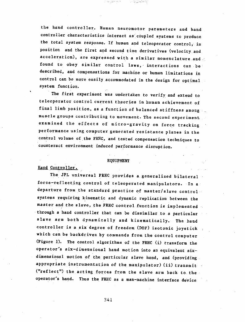
the hand controller. Human neuromotor parameters and hand
controller characteristics interact as coupled systems to produce
the total system response. If human and teleoperator control, in
position and the first and second time derivatives (velocity and
acceleration), are expressed with a similar nomenclature and
found to obey similar control laws," interactions can be'
described, and compensations for machine or human limitations in
control can be more easily accommodated in the design for optimal
system function.
The first experiment was undertaken to verify and extend to
teleoperator control current theories in human achievement of
final limb position, as a function of balanced stiffness among
muse Ie groups contribut ing to movement. The second exper iment,
examined the effects of micro-gravity on force tracking
performance us ing. computer genera ted res istance p lanes in the
control volume of the FRHC, and tested compensation techniques to
counteract environment induced performance disruption.
EQUIPMENT
Rand Controller. --,. The JPL universal FRRC provides a generalized bilateral
force-reflecting control of teleoperated manipulators. In a . .
departure from the standard practice of master/slave control
systems requiring kinematic and dynamic replication between the
master and the slave, the FRHC control function is implemented
, through a hand controller that can be dissimilar to a particular
slave arm both dynamically and kinematically. The hand
controller is a six degree of freedom (DOF) isotonic joystick
whieh can bebackdriven by commands from the control computer
(Figure 1). The control algorithms of the FRRC (i) transform the
operator's six-dimensional hand motion into an equivalent six
dimensional motion of the particular slave hand, and (providing
appropriate instrumentation of the manipulator) (ii) transmit
("reflect") the acting forces fr,om the slave arm back to the
operator's hand. Thus the FRHe as a man-machine interface device
341

performs feedforward and feedback motion, and force
transformation and transmission between the operator's hand and
the remote manipulator's hand.
The FRHC provides feedback to the operator identifying
position and velocity mismatch between the commanded endpoint and
the actual (or simulated) manipulator end point. This feedback
is instituted as a stiffening and damping of the FRHC motion
through active backdrive of torque motors affecting the FRHC
handgrip motion. The controller feedback gains Kp,Kv, and Kf
(for sensor based force reflection) are software manipulable and
were varied in the course of the experimentation reported. These
gains can be varied independently for each of the six DOFs of the
hand controller (Bejczy and Salisbury, 1980).
Simulation Software.
In this investigation the FRHC was decoupled from control a
physical manipulator so that task parameters and disturbance
inputs could be closely contr61led by the experi~enters.
A task simulation system was developed based on the
following concept: the computer, the FRHC and the operator form
a closed loop, the computer simulates a slave arm to be driven
by the FRHC (Figure 2). In the feedforward path, positioning
commands received from the controller are interpreted and
processed in the computer. In feedback, the force and torque
resul ted from the s imu lated task environment are computed and
sent by the computer to the FRHC to back drive the joint motors
(Fong and Corker, 1984).
The simulation system was used in both experiments. to
manipulate the characterisitics of the response of the FRHC to
operator task performance.
EXPERIMENTS
The purpose of the first experiment was to verify and extend
the linear harmonic oscillator model of human neuromotor control
to control of a teleoperator device in three dimensional space.
This verification of the model was undertaken to provide a basis
342

for analyzing performance in the zero gravity performance
scenerio, described in Experiment Two.
Experiment One.
A terminal position for the hand controller was learned in
the three dimensional control space of the FRHC by blindfolded
subjects. The reattainment of that position was subject to
stiffness constraints imposed through the simulation system. The
stiffness imposed, by software specification of stiffness gain
on the three translational axes of motion, either resisted or
augmented the operator's movement to the learned target position.
The conditions of stiffness and the magnitude of the gain were an
operator dependent function based on prior calibration of system
response stability for each partcipant in the study. The
. simulation system provided the capability to (i) specify
augmentative and resistive stiffness vectors for an arbitrary
position in three dimensional operator referenced Cartesian
,coordinates, (ii) record the achieved position (AP) to .01 inch
accuracy in the free space of operator movement. Figure Three
illustrates the task workspace in re.lation to the FRHC.
A repeated measures analysis of variance (ANOVA) was
performed to determine if the target, resisted AP, and augmented
AP differed significantly from each other across subjects, and to
determine if that difference was orthogonal among the axial
coordinates (X,Y,Z) defining those positions.
The analysis indicates a significant effect of stiffness
. gain (Kp) on position. The null hypothesis that stiffness would
not affect achieved position in relation to ,the targe~ is
rejected with a p <.001, (F(2,14) = 18.21). The analysis also
indicates no significant difference among axes of motion, and no
significant interaction between stiffness and axis, th.ereby
supporting the hypothesis that the effect of stiffness gain is
orthogonal among axes.
The, results of this experiment indicate that achievment of
final position in three dimensional space, effected through
coordinated multi-joi,nt motion of a, multi-articulated limb
343

system, is affected by an imposed stiffness on the moving limb.
This effect differs between an augmentative and resitive
stiffness in relation to a target position (learned 1n the
absence of imposed stiffness conditions). The resultant APs are
reliably short of the target in the case of resistive stiffness
and beyond the target in the case of augmentative stiffness.
This directional deviation is orthogonal among the major
translation axes defining the AP in relation to the target. The
model of multi-articulated limb control that can be inferred
from these data is currently under development.
The results support the concept of stiffness balance as a
position specification in human neuromotor control, and provide
an extension of that model to three dimensional positioning with
a control manipulanda. The results indicate a lack of precision
in blind limb placement, even for a trained position,as a
function of an imposed change in the relative stiffness of the
muscles driving the limb movement.
despite the availabilty of kinesthetic
This effect is observed
feedback as to the limb's
actual position. The inference drawn from these, results is that
changes in relative muscle stiffness as a function of a zero g
operating environment could potentially affect blind limb
positioning in control.
Experiment Two.
The second experiment examines the effect of a zero gravity
'operating environment on human performance in manual control of a
teleoperator in a bilateral position control mode. In order to
provide an experimental platform for this research, a mechanical
gravity compensation system for the upper limb has been designed
and fabricated. The system is based in part on work performed at
Case Western University, as reported in NASA CR-1234 (1968). The
system supports the operator's upper arm an hand throughout the
range of motion for control of the force reflecting hand
controller (FRHC)~
The system was designed to meet the following suspension
344

requirements:
1) The compensation system should provide a constant force at
the center of mass of each limb segment that is equal and
opposite the gravity force acting on that limb. Determination of
that force requirement is as follows:
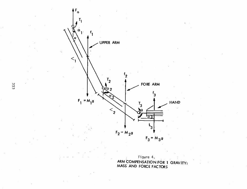
For a limb in an arbitrary positipn in a 19 environment,
Figure 4 illustrates the parameters of interest.
Where:
Fo = Force of support of shoulder girdle
Ml,M2,M3 = Mass of Limb segments
T}JT2,T3 = Torque about shoulder, elbow, and wrist
L1.L2.L3= Length of limb .segments
/11 .1 2 .13 = Length to ce:,oter of mass, for each
segment
91 ,92 .93 = Segment angle to gravity perpendiculat;
Force balance requires that:
Fo = g (Ml + M2 + M3)
l,n this design each limb segment will be supported at the
center of mass of each segment. Consequently, the compens,ation
forces (fl, f2, f3) can be calculated independent of the joint
,torques, assuming frictionless coupling at the joints.
The arm and hand of each subject were analysed to determine
the approximate weight and center of mass of each limb segment
.using anthropometic measurement and regression techniques
developed by Clauser et a1. (1969),. The approxbnate ~eight
determined the particular spring system to be used. Each spring
system was adjustable within a range of +/- ~25 lbs.; as is
described below. The exact segment balance was determined by
examining the response of a suspended and relaxed subject to a
unit pulse disturbance, and adjusting spring tension to result in
a balanced positive and negative amplitude for the respon~e
trajectory.
System Design:
The suspension system consists of two parts:
a) Negator springs to provide a constant gain spring tension
345

for vertical compensation. The torque from the spring can be
adjusted to balance the individual limb segment weight by
selecting the width and breadth of the spring, and adjusting the
selected spring by varying the interior diameter of the spring
coil through adjustment of the radius of the take up spool. The
exact spring characteristic to torque relationship has been
developed for several classes of spring coils. Figure 5 shows
several details. The limb segment is secured using velcro pads
and the placement of the spring support is adjustable.
b) For translational motion and as a support for the negator
springs an x-y roller bearing system was designed and fabricated
(see Figure 5). The system will be adjustable for a standing and
seated operator and mounted in front of the FRHC control/display
panel.
Figure 6 illustrates an operator using the compensation
system and the FRHC in control simulation experiments.
The second experiment made extensive use of the simulation
system capability to configure a software defined interactive
workspace for the FRRC, and to present that workspace to the
operator proprioceptively, through FRHC backdrive.
In this experiment the t'ask was defined as moving the FRHC
along the surface inside or outside a simulated box, atypical
task which can generate force feedback in all possible
directions. The hand contro ller is free moving insidel out side
the 'virtual' box and encounters backdriving force when exceeding
the workspace limits. This backdriving force is determined by
one unique parameter called 'position error' defined as
where·
E is the position error,
X is the hand controller's position,
!o is the workspace limit.
346
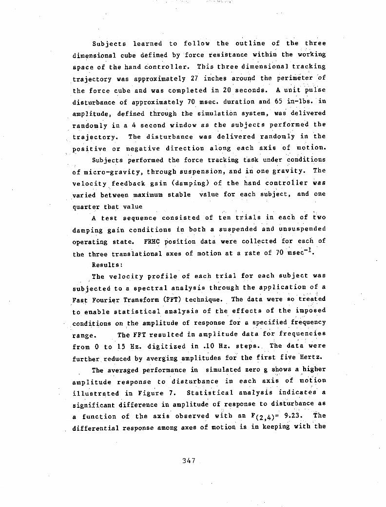
Sub j ect s learned to fo llow the out line of the three
dimensional cube defined by force resistance within the wo;rking
space of the hand controller. This three dimensional tracking
trajectory was approximately 27 i~ches around the perimeter ~f
the force cube and was completed in 20 seconds. A unit purse
disturbance of approximately 70 msec. duration and 65 in-Ibs. in
amplitude, defined through the simulation system, was delivered
rando.ly in a 4 second window as the subjects perfoime~ the
trajectory. The disturbance was delivered randomly in the
positive or negative direction along each axis of motion.
Subjects performed the force tracking task under conditions
of micro-gravity, through suspension, and in one gravity. The , , ,
velocitY,feedback gain (damping) of the hand controller was
varied between maximum stable value for each subject, and one
quarter that value
A test sequence consisted of ten trials in each of two
damping gain conditions in both a suspended and unsuspended
operating state. FRHe position data were collected for each of
the three translational axes of motion at a rate of 70 ~sec-1.' Results:
The velocity profile of each trial for each subject was
subjected to a spectral analysis through the application of a " Fast Fourier Transform (FFT) technique. The data were so" treated
to enable statistical analysis of the effects of the imposed
conditions on the amplitude of response for a specified frequency
range. The FFT resulted in amplitude data for frequencies
from 0 to 15 Hz. digitized in .10 Hz. steps. The data were
further, reduced by averging amplitudes for the first five Hertz.
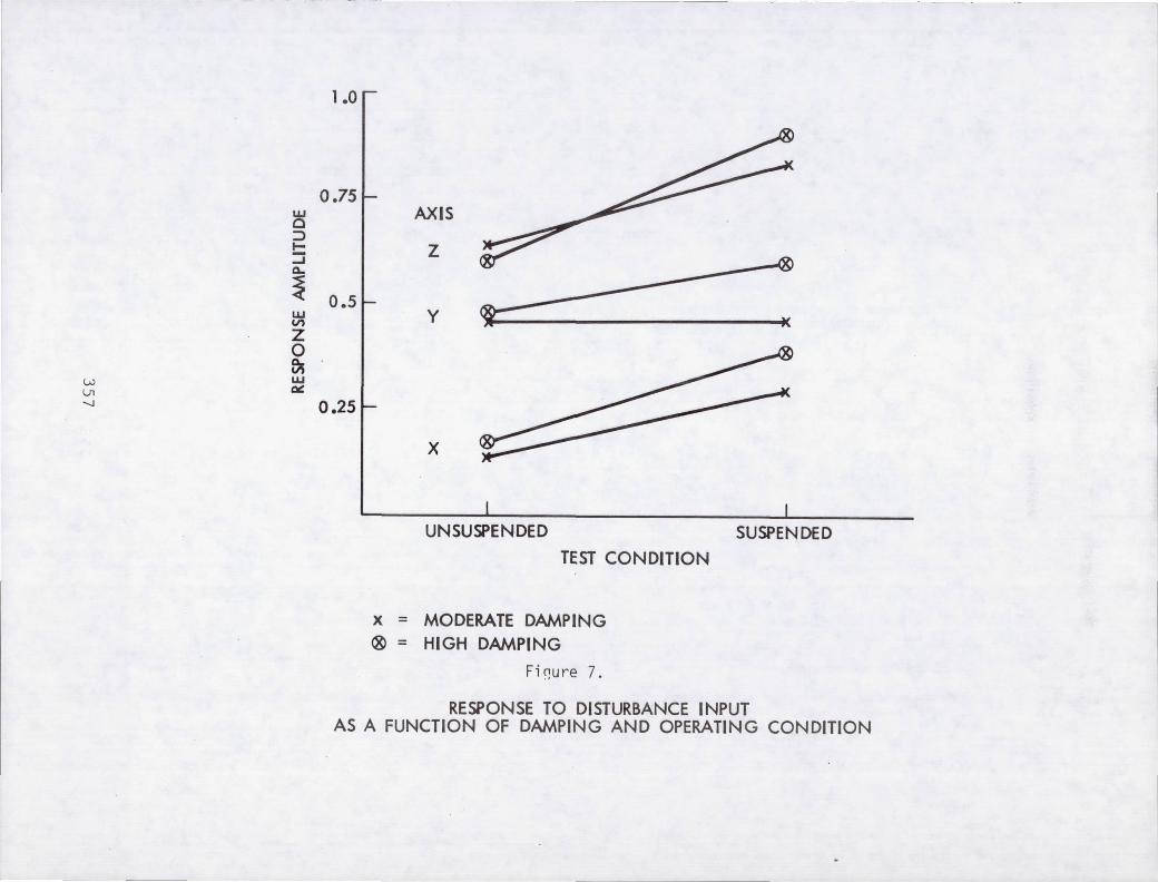
The averaged performance in simulated zero g s~ows a higher
amp litude response to dis turbance in each axis of motion
illustrated in Figure 7. Statistical analysis indicates a
significant difference in amplitude of response to disturbance as
a function of the axis observed with an F(2 4)= 9.23. The , ' ,"
differential response among axes of motion is in keeping with the
347

results of an analysis of damping effects on control reported in
Corker (1984).
The level of damping applied did not result in significant
effects in the averaged data. An analysis of the individual
response to damping was undertaken to investigate this lack of
effect. Figure 8 illustrates the result of this analysis.
Averaged across axes, damping in one g performance has the
expected effect. However, in the suspended condition the response
pattern of the subjects diverged. Group 1 response amplitudes
indicate that the effect of damping is enhanced in the suspended
condition resulting in response amplitudes further reduced than
those of one g performance. Group 2 showed the opposite effect
in response to damping in the suspended condition.
The factors contributing to the differential response to
damping under zero g performance are currently being
investigated. It is hypothesised that some individual's response
to control in the zero g condition result in an impedance
mismatch between control damping and stiffness and the neuromotor
activation state that results in the instability observed.
CONCLUSION
The results indicate the potential utility of rel~tively
simple models of neuromotor control processes in investigati"ng
the interaction of the human operator and controller in
teleoperation. Stiffness manipulation in the cbntrol system
significantly affected the accuracy of final position attainment
in three dimensional space. Gravity compensation for the human
operator through part-simulation resulted in increased
instability in the operator's response to disturbance in a force
tracking task. Additionally, preliminary data indicate that this
increased instability can be successfully compensated, in some
subject's, by selection of hand controller damping and stiffness
parameters to match reduced natural damping which obtains as a
function of the micro-gravity conditions.
348
Acknowledgment
This work has been carried out at the Jet Propulsion Laboratory,
California Institute of Technology, ·unde.r NASA Contract No. NAS7-918.
REFERENCES
'Bejczy, A. K.,and Salisbury, J. K., Jr., Kinesthetic Coupling Between Operator and Remote Manipulat~r, Proceeding's .. Q.f 'ASME C'omputer Technology Conference " Volume 1., San Francisco, CA., August 12-15,n1980;snd, Control1i'Ilg ·RemoteMan1.pulatorsThrough ,Kinesthetic, Coupling, Computers in Mechanica 1 Eng ineer ing, Vo.!. 1 No,.. 1,' Ju ly 19'83, pp. 48-60. . i
Clauser, C. E., J. T.McConville, and J. W. Young, (969) Weight," V.Q.1!!-mh and Center of Mass of the Segments of the 'Human B~ (A'MRL-TR-69-TO), Aerospace Medical Research Laboratory, Wr ight Patterson Airfor.ce Bas,e, Ohio, NASACR 11262. .
Corker, K.' M., Invest iga tion of Neuromotor Cont.ro 1 'Samplirlg in Bilateral Teleoperation, ~h.D Thesis, of Psychology, 1984. " . '.
and Sensory UCLA, .Department
'f' i
Fong, t.P'o' .• ~Uld' Corker ,K~f(1984).' ~orceIT~rque feedback task s imula t.ion fo,·r advanced remote manipu lah>rs .• SociE!tyfor CoDlPuterSimulationSCS Conference, July ,23":25, (In Press).
Hogan,N. (982). Mechanica 1 impedance. control in assis t i ve devices and manipula, tors. in Ro.botMot ion. M. Braqy, J. M. Hollerbach,T. L. Johnson, T. Lozano-Pere~,and 'M. T."Mason (eds.), pp. 631~372, MITPress,Cambridge, Ma.
. '
Morgen, ·R •. J. (19~9). A .. lunar Gray~tySimulator, Volume II. Case Western Reserve University,C1ev.eland, Ohio, NASA CR-1234~
Pol it Ii' A., & Biz z i, E., (1 9 78 ) Pr'o c e ~ s esc 0 n t roll in gar ill movements in monkeys. Science, 201 .(4392), 1235-1237.
349
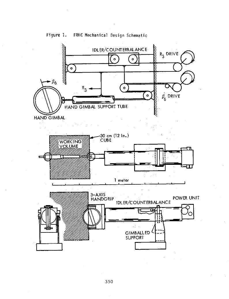
Figure 1. FRHC Mechanical Design Schematic
HAND GIMBAL
IDl ER/cOUNTERBAlANC E·
-HAND GIMBAL SUPPORT TUBE
30 em (12 in.) CUBE
1 meter ,
,
~6 DRIVE
3-AXIS. POWER UNIT HANDGRIP
350
I DL ERic OU NT ERBAL ANC E
GIMBALLED SUPPORT

VJ \JI f-'
JOINT CARTESIAN POSITIONS .l'\ POSITIONS -"\
T COMPUTER 11 - ~ V y
F - SIMULA-R nON I
H IN I -
i
C JOINT . CARTESIAN WORK I A COMMANDS Vt POSITION
K JT
~ ERROR
SPACE ... F - E
Figure 2.
FRHC Backdrive simulation system configuration.

(X = -7.39) Y = -5.89 Z = -7.54
AUGMENTATIVE
Figure 3. Working Volume of FRHC
352
(X == 7.84) Y = 6.01 . Z = 9.16
w VI W
Fo
T. I
fl
/ UPPER ARM
f2
/ FORE ARM
f3
F 1 = M19 /l/HAND I ~
_. HI
F2 = M 29
F3 =M3 9
Figure 4. ARM COMPENSATION FOR 1 GRAVITY: MASS AND FORCE FACTORS

Fi gure 5. Variable Radius Take-up Spool
A 1 ~ .062 ----------------
5/8- 18 THREADS
2.00" f . +.005 - .876 _ .000
t
.220
8 ~ ~ .062
,,----~----------------------
. 2.0" . ,
.65 .77 , ~
354
5/8-18 THREADS
MAKE FROM 7075 T7 ALUM OR QUIV • CONICAL SPOOL NEGATOR SPRING SK ~24-83 REV. 8
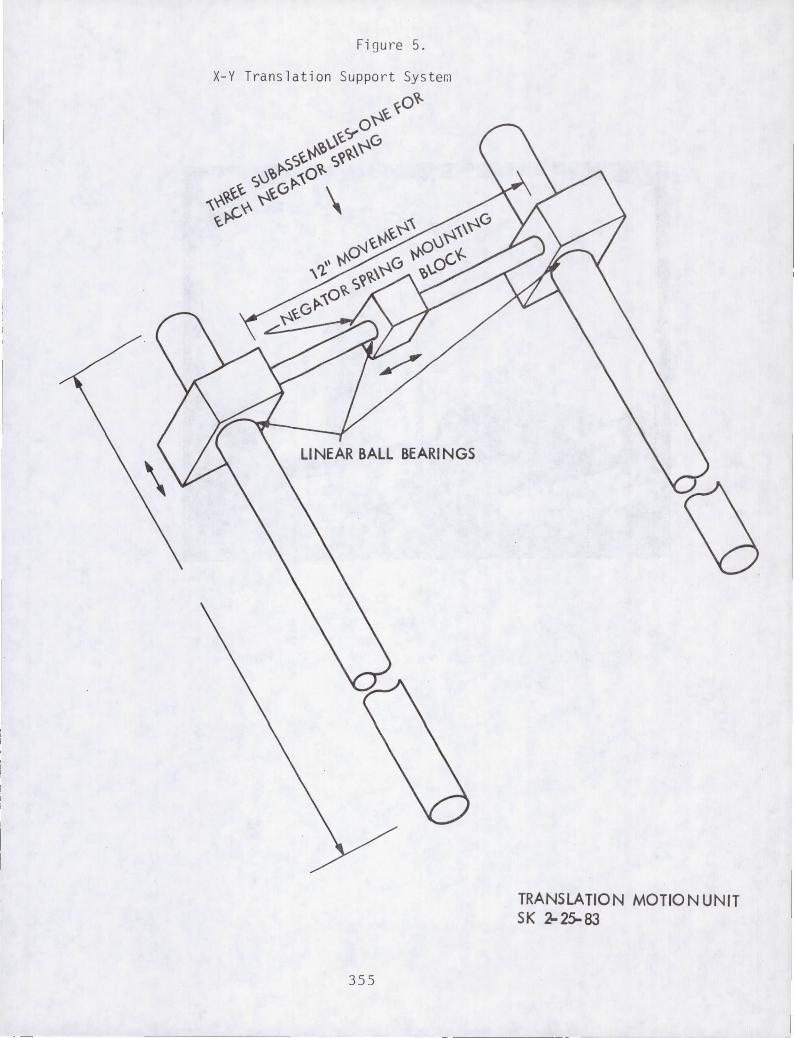
Fi ~ure 5 .
355
TRANSLATION MOTION UNIT SK ~25-83
.J

Fi gu re G. .
Operator Using Suspension System i n Simulation Task.
356
LV VI -....J
----- ---------"--
w c ~ I-::; Q,.
~ w V')
Z 0 ~ w '"
1.0
0.751
0.51
0.25
1
AXIS
Z
Y ,.
X
UNSUSPENDED TEST CONDITION
x = MODERATE DAMPING ® = HIGH DAMPING
Fi~ure 7.
,,,
SUSPENDED
RESPONSE TO DISTURBANCE INPUT AS A FUNCTION OF DAMPING AND OPERATING CONDITION

<1, o
9 ~ I
.I i
I I /
I / / f ,
/ i I
/ I QJ 0 .. ,
I I:: ~ I 0 l-/ 0. 0. :::l :::l 0 0 ~ ~
c.!) c.!)
II II
0 0 <1
co.
, . ----------------------------------------------------~,
r-:.:. \0 o
359
0'1 ..c:: I:: Vl·~
.~ 0. IE
<0 Cl
-0 QJ
-0 I:: QJ Co Vl ::l
(/)
0'1 I:: .~
~o. OE -l <0
Cl
0'1 I::
..c::.~
0'10. .~ E I<O
Cl
-0 QJ -0 I:: QJ 0. Vl :::l Vl I::
::::>
0'1 I::
~.~
00. -lE
<0 Cl
co QJ ~ :::l CT.
l.L