Embed Size (px)
Citation preview
3
C H A P T E R 1
Introduction
Radiance is a professional tool kit for visualizing lighting in virtual environ-ments. It consists of over 50 tools, many of which cannot be found anywhere elseand, because of their almost endless possibilities, may appear complex to the begin-ner. To make it easy to get started, this chapter is written as a completeintroduction; at the end of it, you will be able to create and render scenes of yourown. More advanced concepts are elaborated in the remaining tutorials in thissection.
We start off by illustrating what distinguishes Radiance from other renderingtools, namely its ability to predict reality. Next, we introduce some of the importanttools and concepts that will be needed to understand the material in this book.Finally, we offer a short tutorial, which is designed to give you some immediatehands-on experience with the software.
4 C H A P T E R 1: Introduction. . . . . . . . . . . . . . . . . . . . . . . . . . . . . . . . . . . . . . . . . . . . . . . . . . . . . . . . . . . . . . . . . . . . . . . . . . . . . . . . . . . . . . . . . . . . . . . . . . . . . . . . . . . .. . . . . . . . . . . . . . . . . . . . . . . . . . . . . . . . . . . . . . . . . . . .
1.1 Photorealism and Lighting VisualizationRendering is the process of taking a 3D geometric description and making a 2Dimage from a specific view. This term is taken from traditional practice in architec-tural and artistic drawing, whose rules of perspective were developed centuries ago.These rules have been elaborated, refined, and codified in modern computer-aideddesign (CAD) software. More recent advances in computer lighting models (calledlocal and global illumination models) have developed further into the field known asphotorealistic rendering. In most cases, we call an image photorealistic if it “looks asreal as a photograph.” Although this is a laudable goal, there is still a big differencebetween something that looks real and something that is a good reproduction ofreality. We begin this book with a hypothetical example to illustrate this importantdifference.
Imagine yourself as a third-year design student in the architecture department ofa large university. For your term project, you are charged with the design, modeling,and rendering of a three-story office complex. In addition to design drawings, youmust produce full-color renderings of the inside and outside of your structure. Youmay produce the renderings by hand or using computer software. In addition, youmust produce a daylight study of one room in your structure, using whatever meansyou have available. Most students are building scale models of their designs to pho-tograph outdoors, but you want to use the computer both for renderings and fordaylight analysis. (After all, the CAD program you are using, DesignWorkshop, hassettings for the time of day and time of year and claims to do solar studies.)
The design and modeling phases of your project go well, and soon you have acomplete set of drawings to hand in. You then turn your attention to rendering anddaylighting analysis. You have some success rendering exterior views of your build-ing, though you are a bit disappointed by the flat shading produced by the CADsoftware, which gives your renderings the sort of cheesy look so familiar in com-puter graphics. You do learn how to set the solar position, though, and you areemboldened to attempt rendering the interior for your daylight study.
Much to your dismay, you find that no matter how hard you try, you cannot getanything even remotely believable for your interior views. You finally decide thatthe CAD software is just not up to the task, and look into some of the other ren-dering programs at your disposal. You have heard good things about 3-D Studio,so you make use of the export and import options to get your model over to thispackage and start to play around with it. First, you struggle for some time to get thesun in a known position, since the coordinate system is different and there is noclear mechanism for getting the right kind of light source in the right place. Finally,you get yourself reoriented and generate a view of the interior. Although the results
1.1 Photorealism and Lighting Visualization 5. . . . . . . . . . . . . . . . . . . . . . . . . . . . . . . . . . . . . . . . . . . . . . . . . . . . . . . . . . . . . . . . . . . . . . . . . . . . . . . . . . . . . . . . . . . . . . . . . . . . . . . . . . . . .. . . . . . . . . . . . . . . . . . . . . . . . . . . . . . . . . . . . . . . . . . .
are an improvement over the CAD renderings, they still look very strange, and lightis not bouncing around as you would expect. There is a sun patch on the floor,which you expected, but no light from this patch is reflected to the rest of the room.In fact, the rest of the room appears to have a constant illumination that is unrelatedto the light coming in. (You try a number of sun positions to verify this hypothesis.)
After spending some time with the 3-D Studio manual, you decide that the onlyway to get the effects you are looking for is to create what are called “ambientlights,” invisible sources of illumination that brighten up those parts of the roomyou expect to be bright. You experiment with these imaginary sources for a whileuntil you get some results that you think are worth showing to your instructor. Yourinstructor looks at them, then asks you a very annoying question: “How do youknow this is what it will look like?”
You think about this for a moment before realizing that all you have done is cre-ate a rendering that meets your expectations! In fact, you have learned nothingabout daylight in the process, and you have no real confidence that the actual spacewill look anything like your rendering. Since the purpose of a daylight study is todetermine how well a building lets light into its interior, this method of renderingis useless because it is not predictive. It may be photorealistic, since it looks as if itcould be a real photograph, but it isn’t accurate, because it has no physical basis inreality. Light does not interact in your rendering system the same way it would ina real environment, so the results are not true to reality. In fact, you had to intro-duce completely nonphysical, nonexistent sources into the model just to get it tolook reasonable; you spent a lot of extra time and gained no new insights in theprocess.
Fortunately, you have another option. Using the Radiance export facility ofDesignWorkshop, you can render your model with a valid lighting visualizationprogram. Between the reference manual on the CD-ROM and the short tutorial atthe end of this chapter, you can learn enough about the programs and material def-initions to complete your exported model and generate some simple renderings.From Chapter 6, Daylight Simulation, you can learn the basics of accurate daylightcalculation, and you will soon be generating some very nice renderings of your inte-rior, renderings that not only look great but are predictive of the way the real spacewould appear. As a bonus, you can also determine accurate daylight factors at var-ious points in the room, and your exterior renderings will look better as well.
This story illustrates the difference between photorealistic rendering and lightingvisualization. The former is useful in situations where you only want to fool theaudience into thinking it’s real. The latter is what’s needed when the appearance inthe rendering must match actual physical conditions. An additional benefit oflighting visualizations is that they often look more realistic as well, since they do infact correspond much better to reality.
6 C H A P T E R 1: Introduction. . . . . . . . . . . . . . . . . . . . . . . . . . . . . . . . . . . . . . . . . . . . . . . . . . . . . . . . . . . . . . . . . . . . . . . . . . . . . . . . . . . . . . . . . . . . . . . . . . . . . . . . . . . .. . . . . . . . . . . . . . . . . . . . . . . . . . . . . . . . . . . . . . . . . . . .
1.1.1 Requirements for Lighting Visualization
The first requirement for a valid lighting visualization program is that it correctlysolve the global illumination problem. Specifically, it must compute the ways lightbounces among the various surfaces in the 3D model. If absolute quantities aredesired from the simulation, it must further perform its computation in physicalunits, such as units of radiance or radiant exitance (radiosity).
The second requirement, which is equally important, is that the local illumina-tion model also adhere to physical reality. This model describes the way light isemitted, reflected, and transmitted by each surface. Many lighting visualizationprograms are based on the radiosity method [Ash94] [SP94], which typically modelssurfaces as ideal Lambertian diffusers. This is at best a gross simplification, but it isa very convenient one to make, computationally speaking. The best methodsinclude specular and directional-diffuse reflection as well, as in Radiance. (Note: Donot confuse the units with the methods named after them. See the Glossary for fur-ther explanations.) Most important, the local illumination model must include anaccurate simulation of emission from light sources, because if this is not done cor-rectly, nothing done afterward can save the result.
Past these basic requirements, there are some important practical issues to con-sider. Although opinions differ, we believe that the following goals must be met byany useful lighting visualization system, and that these capabilities are intrinsic toRadiance:
• Accurately calculates luminance and radiance. Luminance is the photometricunit that is best correlated with what the human eye actually sees. Radiance isthe radiometric equivalent of luminance, and is expressed in SI (Standard Inter-national) units of watts/steradian/m2. Radiance (the software) endeavors toproduce accurate predictions of these values in modeled environments, and in sodoing permits the calculation of other, derived metrics (for all metrics are deriv-able from this basic quantity) as well as synthetic images (renderings).
• Models both electric light and daylight. Since Radiance is designed for generallighting prediction, we wish to include all important sources of illumination. Forarchitectural spaces, the two critical sources are electric light and daylight. Mod-eling electric light accurately means using measured and/or calculated outputdistribution data for light fixtures (luminaires). Modeling daylight accuratelymeans following the initial intense radiation from the sun and redistributing itthrough its various reflections from other surfaces, and scattering from the sky.(Section 3.1 demonstrates the use of IES luminaire data and shows how to setup daylight simulations.)
1.1 Photorealism and Lighting Visualization 7. . . . . . . . . . . . . . . . . . . . . . . . . . . . . . . . . . . . . . . . . . . . . . . . . . . . . . . . . . . . . . . . . . . . . . . . . . . . . . . . . . . . . . . . . . . . . . . . . . . . . . . . . . . . .. . . . . . . . . . . . . . . . . . . . . . . . . . . . . . . . . . . . . . . . . . .
• Supports a variety of reflectance models. The accuracy of a luminance or radi-ance calculation depends critically on the accuracy of the surface reflectancemodel, because that determines as much as the illumination how light will bereturned to the eye. Radiance includes some 25 different surface material types,one of which is an arbitrary bidirectional reflectance-transmittance distributionfunction (BRTDF). Each material type has several tunable parameters thatdetermine its behavior, and many have procedural and data inputs as well. Inaddition, these basic materials can be combined in all manners with 12 differentpattern and texture types, and even with each other. Most important, everymaterial type is based on reasonable approximations to the physics of light inter-action with particular surfaces, rather than derived with the more prevalentmotive of algorithmic convenience.
• Supports complicated geometry. Great efforts are made in Radiance to minimizethe impact of complicated geometry on the memory and processing require-ments. Storage complexity increases linearly with the number of surfaces, andcomputational complexity increases sublinearly, on the order of the cube root ofthe number of surfaces or less. To further reduce the memory overhead of com-plicated scenes, Radiance employs instancing to maintain a list of repeated objectsand their occurrences in the scene. Using this technique, it is possible to modelscenes (such as a forest) with millions of surface primitives in only a few mega-bytes of RAM.
• Takes unmodified input from CAD systems. One of the basic precepts of Radi-ance is that scene geometry can be taken from almost any source. We think it isunreasonable to restrict you to a rendering system for creating your geometrywhen CAD systems are available for just this purpose. We also think it is unrea-sonable to require you to condition your CAD models by orienting surfacenormals or meshing surfaces, since this is pointless drudgery and must berepeated if the model is regenerated. The one requirement in Radiance is thatthere be some way to associate materials with surfaces, and this is more a prereq-uisite for interesting renderings than it is a Radiance-specific requirement.
Now that we have outlined what Radiance does, let us look at how well it does it.
1.1.2 Examples of Lighting Visualization
Plate 1 shows a Radiance rendering of a conference room. The model for this roomwas derived by measuring the dimensions of the real space and furnishings shownin Plate 2. The similarity between the two images testifies to the accuracy of theluminance calculation, even if no numeric values are shown. Plate 3 shows the sameimage with superimposed isolux contours indicating lines of equal illumination on
8 C H A P T E R 1: Introduction. . . . . . . . . . . . . . . . . . . . . . . . . . . . . . . . . . . . . . . . . . . . . . . . . . . . . . . . . . . . . . . . . . . . . . . . . . . . . . . . . . . . . . . . . . . . . . . . . . . . . . . . . . . .. . . . . . . . . . . . . . . . . . . . . . . . . . . . . . . . . . . . . . . . . . . .
room surfaces. A lighting designer or architect could use this numerical informa-tion to assess the adequacy of the electric lights in simulation before installing themin reality.
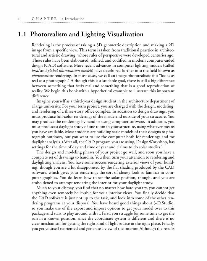
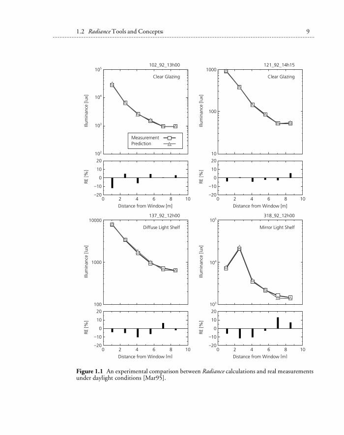
Figure 1.1 shows a comparison between measured illuminance values under day-light conditions and Radiance predictions based on simultaneous measurements ofthe sun and sky components [Mar95]. This attests to the numeric accuracy of thedaylight calculation in Radiance.
Plate 4 shows a Radiance rendering of a daylighted office space. Plate 5 shows aphoto of the actual space, taken under similar conditions. The reflectance functionof the table was measured with a gloss meter, and these measurements were used inassigning the reflectance properties in Radiance. Again, the similarity between thetwo images testifies to the accuracy of the calculation.
Plate 6 demonstrates some of the material properties that can be modeled inRadiance. The candleholders exhibit anisotropic reflection as though the metal hadbeen brushed circumferentially. The table also shows anisotropic behavior becauseof the application of varnish over the woodgrain, which can be seen in the elon-gated highlights from two candles. The woodgrain pattern was taken from ascanned photograph and staggered with a user-defined coordinate mapping proce-dure. Finally, the silver box displays an anisotropic reflection pattern modeled withanother procedure that simulates the effect of carving many S-shaped grooves in thesurface. Plate 7 shows the same scene rendered with diffuse surfaces, such as onemight obtain from a view-independent radiosity system.
Plate 8 shows the interior of a stadium, which was modeled with AutoCAD andthen exported to Radiance for rendering. The scene contains tens of thousands ofsurfaces. Plate 9 shows the exterior of the same structure. The trees were includedas instances, each one including many thousands of surfaces but requiring only afew bytes of additional memory.
1.2 Radiance Tools and ConceptsRadiance is a lighting simulation program that synthesizes images from 3D geomet-ric models of physical spaces. The input model describes each surface’s shape, size,location, and composition. A model often contains many thousands of surfaces,and is often produced by a separate CAD program. Besides arbitrary (planar) poly-gons, Radiance directly models spheres and cones. Generator programs are providedfor the creation of more complex shapes from these basic surface primitives. Exam-
1.2 Radiance Tools and Concepts 9. . . . . . . . . . . . . . . . . . . . . . . . . . . . . . . . . . . . . . . . . . . . . . . . . . . . . . . . . . . . . . . . . . . . . . . . . . . . . . . . . . . . . . . . . . . . . . . . . . . . . . . . . . . . .. . . . . . . . . . . . . . . . . . . . . . . . . . . . . . . . . . . . . . . . . . .
Figure 1.1 An experimental comparison between Radiance calculations and real measurementsunder daylight conditions [Mar95].
Radiance Tools and Concepts
10 C H A P T E R 1: Introduction. . . . . . . . . . . . . . . . . . . . . . . . . . . . . . . . . . . . . . . . . . . . . . . . . . . . . . . . . . . . . . . . . . . . . . . . . . . . . . . . . . . . . . . . . . . . . . . . . . . . . . . . . . . .. . . . . . . . . . . . . . . . . . . . . . . . . . . . . . . . . . . . . . . . . . . .
ples include boxes, prisms, and surfaces of revolution. A transformation utilitypermits the simple duplication of objects and the hierarchical construction of ascene.
To be more specific about what Radiance does, let’s look at some of its featuresone at a time. We will start by breaking the calculation into segments for clearerdiscussion. These are
• Scene geometry: the model used to represent the shapes of objects in an environ-ment, and the methods for entering and compiling this information
• Surface materials: the mathematical models used to characterize light interactionwith surfaces
• Lighting simulation and rendering: the technique used to calculate light propaga-tion in an environment and the nature of the values computed
• Image manipulation and analysis: image processing and conversion capabilities• Integration: interconnection and automation of rendering and analysis processes,
and links to other systems and computing environments
1.2.1 Scene Geometry
Scene geometry within the rendering programs is modeled using boundary represen-tation (B-rep) of three basic surface classes, defined below.
• Polygon: An n-sided planar polygon, with no fewer than three sides. A polygonmay be concave or convex as long as it is a well-defined surface (i.e., no two sidesmay intersect, though they may coincide). Surface orientation is determined byvertex ordering. Vertices read counterclockwise from the front. Holes in poly-gons are represented using seams. If the vertices are nonplanar, a warning is issuedand the average plane is used, which may result in cracks in the rendering of adja-cent surfaces.
• Sphere: Defined by a center and a radius. Its surface may point outward orinward.
• Cone: Includes the truncated right cone, the truncated right cylinder, and thering (a disk with an inner and an outer radius).
Each surface primitive is independent in the sense that there is no sharing of ver-tices or other geometric information between primitives. Besides the above-mentioned local geometric types, there is one distant geometric type:• Source: A direction and subtended angle indicating a solid angle of light entering
the environment, such as light that might come from the sun or the sky.
1.2 Radiance Tools and Concepts 11. . . . . . . . . . . . . . . . . . . . . . . . . . . . . . . . . . . . . . . . . . . . . . . . . . . . . . . . . . . . . . . . . . . . . . . . . . . . . . . . . . . . . . . . . . . . . . . . . . . . . . . . . . . . .. . . . . . . . . . . . . . . . . . . . . . . . . . . . . . . . . . . . . . . . . . .
From this short list of geometric entities, you might conclude that the geometricmodel of Radiance is very limited. If it were not for the object manipulators andgenerators, you might be right. Because generator commands are placed inline,their output is expanded as more input, effectively adding to the geometric entitiessupported by Radiance. Some of these commands are listed below:
• xform: Scales, rotates, and moves Radiance objects and scene descriptions. Com-bined with the inline command expansion feature, permits easy creation of ascene hierarchy for easy modification and manipulation of complex environ-ments. Also provides an array feature for repeating objects.
• genbox: Creates a parallelepiped with sharp, beveled, or rounded corners.• genprism: Creates a truncated prism, extruded from a specified polygon along a
given vector. Optionally rounds corners.• genrev: Generates a surface of revolution based on a user-defined function and
a desired resolution. The resulting object is built out of stacked cones.• genworm: Generates a variable-radius “worm” along a user-specified parametric
curve in 3D space. The object is built out of cones joined by spheres.• gensurf: Generates a general parametric surface patch from a user-defined func-
tion or data set. The object is created from optionally smoothed quadrilateralsand triangles.
• gensky: Generates a description of a clear, intermediate, overcast, or uniform sky,with or without a sun.
• replmarks: Replaces special “mark” polygons with object descriptions. Useful forseparating light sources or detail geometry for manipulation in a CAD system.
Although it is possible to create highly sophisticated scene geometries usingnothing more than a text editor and the primitives and programs included withRadiance, most people prefer to use a CAD program to create their scenes. Trans-lator programs for a few different CAD formats are included with the mainRadiance software. Others are available from the ftp site (ftp://radsite.lbl.gov/;http://radsite.lbl.gov/radiance/) or other sources. Listed below are some of the trans-lators we can recommend.
• archicad2rad: converts from ArchiCAD RIB exports to Radiance (forMacintosh)
• arch2rad: converts from Architrion Text Format to Radiance• arris2rad: converts ARRIS Integra files to Radiance• dem2rad: converts from Digital Elevation Maps to gensurf input• ies2rad: converts from the IES standard luminaire file format to Radiance• mgf2rad: converts from the Materials and Geometry Format to Radiance• nff2rad: converts from Eric Haines’s Neutral File Format to Radiance
Radiance Tools and Concepts
12 C H A P T E R 1: Introduction. . . . . . . . . . . . . . . . . . . . . . . . . . . . . . . . . . . . . . . . . . . . . . . . . . . . . . . . . . . . . . . . . . . . . . . . . . . . . . . . . . . . . . . . . . . . . . . . . . . . . . . . . . . .. . . . . . . . . . . . . . . . . . . . . . . . . . . . . . . . . . . . . . . . . . . .
• obj2rad: converts from Wavefront’s .obj format to Radiance• radout: converts ACAD R12 to Radiance (ADS-C add-on utility)• rad2mgf: converts from Radiance to the Materials and Geometry Format• stratastudio: converts Macintosh StrataStudio files to Radiance• thf2rad: converts from the GDS Things File format to Radiance• tmesh2rad: converts a basic triangle-mesh to Radiance• torad: converts from DXF to Radiance (AutoLISP routine must be loaded from
within AutoCAD)
In addition to the listed surface primitive types, generators, manipulators, andtranslators, Radiance includes two additional features to make geometric modelingsimpler and more efficient:
• Antimatter. Antimatter is a pseudomaterial that can be used to subtract portionsof a surface, implementing a sort of crude constructive solid geometry (CSG).CSG normally provides all possible Boolean operations between two volumes,including union and intersection. However, subtraction is the most useful oper-ation after union, and union is provided by default when two opaque surfacesintersect in Radiance. (This occurs by virtue of the fact that the inside is not vis-ible from the outside.)1
• Instance. An instance is defined in terms of a Radiance octree, which contains anynumber of surfaces confined to a region of space. Multiple occurrences of thesame octree in a given scene will use only as much memory as that required fora single instance, plus some small amount of additional memory to store theassociated transformations for each instance’s location. This mechanism is mostfrequently used for furnishings and the like, but can be applied to nearly any-thing, from building parts to a collection of furniture to trees in a forest.Radiance scenes including millions of surface primitives have been renderedusing this technique.
When the geometry has been defined in one or more scene files, this informationis compiled into an octree using the oconv command. The octree data structure isnecessary for efficient rendering, and for including geometry with the instanceprimitive. The oconv program compiles one or more Radiance scene descriptionfiles into an octree file, which the rendering programs require to accelerate the ray-tracing process. In this book, the .oct extension is added as a convention to identifyoctrees produced by oconv.
1. Note that there are many limitations associated with the implementation of antimatter. Most notably, two antimat-ter objects cannot intersect, or chaos will result. It is generally wiser, therefore, to express the desired object by conventional B-rep methods, such as collections of triangles.
1.2 Radiance Tools and Concepts 13. . . . . . . . . . . . . . . . . . . . . . . . . . . . . . . . . . . . . . . . . . . . . . . . . . . . . . . . . . . . . . . . . . . . . . . . . . . . . . . . . . . . . . . . . . . . . . . . . . . . . . . . . . . . .. . . . . . . . . . . . . . . . . . . . . . . . . . . . . . . . . . . . . . . . . . .
The following example converts three scene description files into an octree inputfile:
% oconv materials.rad objects.rad lighting.rad > scent.oct
1.2.2 Surface Materials
Although the geometric model is very important, equally important to a renderingalgorithm is its representation of materials, which determines how light interactswith the geometry. The most sophisticated geometric model in the world will lookmundane when rendered with a simple diffuse-plus-Phong shading model. (Mostradiosity programs are purely diffuse.)
For this reason, Radiance pays careful attention to materials, more perhaps thanany other rendering system. Version 3.1 has 25 material types and 12 other modi-fier types. Many modifiers also accept data and/or procedures as part of theirdefinitions. This adds up to unprecedented flexibility and generality, and to a littlebit of confusion. It is sometimes difficult to choose from among so many possibil-ities the primitive that is appropriate for a particular material. Let’s look at a few ofthe choices:
• Light: Light is used for an emitting surface, and it is by material type that Radi-ance determines which surfaces act as light sources. Lights are usually visible in arendering, as opposed to many systems that employ non-physical sources, thenhide the evidence. A pattern is usually associated with a light source to give it theappropriate directional distribution. Lights do not reflect.
• Illum: Illum is a special light type for secondary sources, sometimes called impos-tors. An example of a secondary source is a window where sky light enters a room.Since it is much more efficient for the calculation to search for light sources,marking the window as an illum can improve rendering quality without addingto the computation time.
• Plastic: Despite its artificial-sounding name, most materials fall into this cate-gory. A plastic surface has a color associated with diffusely reflected radiation,but the specular component is uncolored. This type is used for materials such asplastic, painted surfaces, wood, and nonmetalic rock.
• Metal: Metal is exactly the same as plastic, except that the specular componentis modified by the material color.
Radiance Tools and Concepts
14 C H A P T E R 1: Introduction. . . . . . . . . . . . . . . . . . . . . . . . . . . . . . . . . . . . . . . . . . . . . . . . . . . . . . . . . . . . . . . . . . . . . . . . . . . . . . . . . . . . . . . . . . . . . . . . . . . . . . . . . . . .. . . . . . . . . . . . . . . . . . . . . . . . . . . . . . . . . . . . . . . . . . . .
• Dielectric: A dielectric surface refracts and reflects radiation and is transparent.Common dielectric materials include glass, water, and crystals. A thin glass sur-face is best represented using the glass type, which computes multiple internalreflections without tracing rays, thus saving significant rendering time withoutcompromising accuracy.
• Trans: A trans material transmits and reflects light with both diffuse and specularcomponents going in each direction. This type is appropriate for thin translu-cent materials.
• BRTDfunc: This is the most general programmable material, providing inputsfor pure specular, directional diffuse, and diffuse reflection and transmission.Each component has an associated (programmable) color, and reflectances maybe different when seen from each side of the surface. The disadvantages of usingthis type are its complexity and the fact that directional diffuse reflections are notcomputed with Monte Carlo sampling as they are for the built-in types.
Most other material types are variations on those listed above, some using dataor functions to modify the directional-diffuse component. Other variations provideanisotropy (elongation) in the highlights for materials such as brushed aluminumand varnished wood. Finally, there are a few other light source materials for con-trolling this part of the calculation and materials for generating virtual light sourcesby specular reflection or redirection of radiation.
All material types also accept zero or more patterns or textures, which modify thelocal color or surface orientation according to user-definable procedures or data.This mechanism is very general and thus also serves as a source of confusion for theuser, so we will spend some time on the subject in the tutorials.
1.2.3 Lighting Simulation and Rendering
Radiance employs a light-backwards ray-tracing method, extended from the origi-nal algorithm introduced to computer graphics by Whitted in 1980 [Whi80].Light is followed along geometric rays from the point of measurement (the viewpoint or virtual photometer) into the scene and back to the light sources. The resultis mathematically equivalent to following light forward, but the process is generallymore efficient because most of the light leaving a source never reaches the point ofinterest. To take a typical example, a 512-by-512-pixel rendering of a bare lightbulb in a lightly colored room would take about a month on the world’s fastestsupercomputer using a naive forward ray-tracing method. The same renderingtakes about three seconds using Radiance. (Mind you, we are talking about a veryfast computer here.)
1.2 Radiance Tools and Concepts 15. . . . . . . . . . . . . . . . . . . . . . . . . . . . . . . . . . . . . . . . . . . . . . . . . . . . . . . . . . . . . . . . . . . . . . . . . . . . . . . . . . . . . . . . . . . . . . . . . . . . . . . . . . . . .. . . . . . . . . . . . . . . . . . . . . . . . . . . . . . . . . . . . . . . . . . .
The chief difficulty of light-backwards ray tracing as practiced by most renderingsoftware is that it is an incomplete model of light interaction. In particular, the orig-inal algorithm fails for diffuse interreflection between objects, which it usuallyapproximates with a constant “ambient” term in the illumination equation. With-out a complete computation of global illumination, a rendering method cannotproduce accurate values and is therefore of limited use as a predictive tool. Radianceovercomes this shortcoming with an efficient algorithm for computing and cachingindirect irradiance values over surfaces, while also providing more accurate and real-istic light sources and surface materials.
Physically accurate rendering of realistic environments requires very carefultreatment of light sources, since they are the starting points of all illumination. Ifthe direct component is not computed properly, it does not matter what happensafterwards, since the calculation is garbage. Most rendering systems, since they donot care much about accuracy, pay little attention to direct lighting. In fact, thebasic illumination equations frequently disobey simple physical laws for the sake ofuser convenience, allowing light to fall off linearly with distance from a pointsource, or even to remain constant.
The details of the local and global illumination algorithms in Radiance aredescribed in Part III, Calculation Methods, Chapters 10 through 15. Here, we willonly mention the main rendering programs and what they produce:
• rview: The interactive program for scene viewing. The displayed resolution isprogressively refined until the user enters a command to change the view or otherrendering parameters. This is meant primarily as a quick way to preview a scene,check for inconsistencies and light placement, and select views for final, high-quality rendering with rpict.
The example below selects an initial camera location (-vp: vantage point) 10 feetalong the negative y-axis, looking in the positive y direction (-vd: view direction)with up in the positive z direction (-vu: view up). An ambient light level (-av:ambient value) is added, enabling the shadowed areas to be illuminated in thescene.oct data set.
% rview -vd 0 1 0 -vp 0 -10 0 -vu 0 0 1 -av .1 .1 .1 scene.oct
• rpict: This rendering program produces the highest-quality raw (unfiltered) pic-tures. A Radiance picture is a 2D collection of real color radiance values, which,unlike a conventional computer graphics image, is also valuable for lighting visu-alization and analysis. The picture is not generally viewed until the renderingcalculation is complete and the output has been passed through pfilt for expo-sure adjustment and antialiasing.
Radiance Tools and Concepts
16 C H A P T E R 1: Introduction. . . . . . . . . . . . . . . . . . . . . . . . . . . . . . . . . . . . . . . . . . . . . . . . . . . . . . . . . . . . . . . . . . . . . . . . . . . . . . . . . . . . . . . . . . . . . . . . . . . . . . . . . . . .. . . . . . . . . . . . . . . . . . . . . . . . . . . . . . . . . . . . . . . . . . . .
The example below creates an image taken from a virtual camera located and ori-ented by the view file (-vf) scene.vf. This view was determined, then written intothe scene.vf file, using functions built into rview. The image will be 512 pixelssquare, and the program will report the status of the rendering progress every 30seconds. The output of rpict, namely the picture, is redirected (>) into thescene.pic file. In this book, the .vf extension is added to view files and .pic topictures.
% rpict -vf scene.vf -x 512 -y 512 -t 30 scene.oct > scene.pic
• rtrace: This program computes individual radiance or irradiance values for light-ing analysis or other custom applications. Input is a scene octree (as for rview andrpict) plus the positions of the desired point calculations. This program is oftencalled as a subprocess by other Radiance programs or scripts.
As we have mentioned above, rtrace is also employed by other Radiance pro-grams to evaluate radiance or irradiance for other types of analysis. For example,mkillum computes radiance entering through windows, skylights, and other “sec-ondary sources” where concentrated illumination can be better represented in thecalculation using the illum primitive. (Secondary sources are introduced in thetutorial at the end of this chapter and explored in detail in Chapters 6 and 13.)Another program that calls rtrace is findglare, which locates and quantifies glaresources in a scene. Here is a list of similar lighting analysis tools.
• dayfact: An interactive script to compute illuminance values and daylight factorson a specified work plane. Output is one or more contour line plots.
• findglare: An image and scene analysis program that takes a picture and/oroctree and computes bright sources that would cause discomfort glare in ahuman observer.
• glare: An interactive script that simplifies the generation and interpretation offindglare results. Produces plots and values.
• glarendx: A back end to convert findglare output to one of the supported glareindices. Also called glare.
• mkillum: Converts specified scene surfaces into illum secondary sources formore efficient rendering.
The findglare program is particularly interesting because it will accept a Radiancepicture as input as well as the original scene description for rtrace. Since a picturein Radiance contains physical radiance values, it is equivalent to a large collectionof rtrace evaluations, and findglare takes advantage of this fact. In the next section,we look at some of the other Radiance tools tailored specifically for pictureprocessing.
1.2 Radiance Tools and Concepts 17. . . . . . . . . . . . . . . . . . . . . . . . . . . . . . . . . . . . . . . . . . . . . . . . . . . . . . . . . . . . . . . . . . . . . . . . . . . . . . . . . . . . . . . . . . . . . . . . . . . . . . . . . . . . .. . . . . . . . . . . . . . . . . . . . . . . . . . . . . . . . . . . . . . . . . . .
1.2.4 Image Manipulation and Analysis
As we mentioned in the preceding section, a Radiance picture is unlike any othercomputer graphics image you are likely to encounter. First and foremost, the pixelvalues are real numbers corresponding to the physical quantity of radiance(recorded in watts/steradian/m2). These values are stored in a compact, 4-byte/pixel, run-length encoded format. (See the File Formats section of the CD-ROM for more details.) Second, the ASCII header contains pertinent informationon the generating commands, view options, exposure adjustments, and color valuesthat can be used to recover pixel ray parameters and other information needed forvarious types of image processing.
The most essential Radiance image manipulation program is pfilt, which adjuststhe picture exposure and performs antialiasing by filtering the original image downto a lower resolution. (This is called supersampling.) More advanced features includethe ability to adaptively filter overbright pixels caused by inadequate sampling[RW94] and add optional star patterns. Here is a list of the most important Radi-ance picture manipulators.
• falsecolor: Converts a picture to a false-color representation of luminance valueswith a corresponding legend for easy interpretation. (See Plate 3 for an example.)Options are included to compute contour lines and superimpose them onanother (same-size) picture, change scales and interpretations, and printextrema. This program is actually implemented as a C-shell script, which callsother programs such as pcomb and pcompos.
• macbethcal: Calibrates color and contrast for scanned images based on a scan ofthe Macbeth Color Checker chart. May also be used to compute color and con-trast correction for output devices such as film recorders. Output is a pixel-mapping function for pcomb or pcond.
• pcomb: Manipulates pixel values in arbitrary ways based on the functional pro-gramming language used throughout Radiance.
• pcompos: Composites pictures together in any desired montage.• pcond: Conditions pictures for output to specific devices, compressing the
dynamic range as necessary to fit within display capabilities [LRP97]. Also takescalibration files from macbethcal.
• pextrem: Finds and returns the minimum and maximum pixel values andlocations.
• pfilt: Performs antialiasing and exposure adjustment. A picture is not really fin-ished until it has passed through this filter.
• pflip: Flips pictures left-to-right and/or top-to-bottom.
Radiance Tools and Concepts
18 C H A P T E R 1: Introduction. . . . . . . . . . . . . . . . . . . . . . . . . . . . . . . . . . . . . . . . . . . . . . . . . . . . . . . . . . . . . . . . . . . . . . . . . . . . . . . . . . . . . . . . . . . . . . . . . . . . . . . . . . . .. . . . . . . . . . . . . . . . . . . . . . . . . . . . . . . . . . . . . . . . . . . .
• pinterp: Interpolates or extrapolates pictures with corresponding z-buffers asproduced by rpict. Often used to compute in-between frames to speed up walk-through animations.
• protate: Rotates a picture 90 degrees clockwise.• pvalue: Converts between Radiance picture format and various ASCII and raw-
data formats for convenient manipulation.• ximage: Displays one or more Radiance pictures on an X11 windows server. Pro-
vides functions to query individual and area pixel values and computes rayorigins and directions for input to rtrace.
In addition, there are many programs to convert to and from foreign image for-mats, such as AVS, PICT, PPM, Sun rasterfile, PostScript, and Targa. Theseprograms have names of the form ra_fmt, where fmt is the commonly used abbre-viation or filename extension for the foreign image format. For example, ra_ppmconverts to and from Poskanzer Pixmap formats. In most cases, reverse conversions(importing into Radiance) are supported by the same program with a -r option.However, a few reverse conversions are too difficult or cumbersome and are notsupported. This is the case for the Macintosh PICT and PostScript formats. Inother cases, not all representations within the defined format are recognized, suchas TIFF, which contains almost too many data tags to enumerate, including a rawFAX type—the data stream sent over a phone line!
1.2.5 Integration
Having all these individual tools provides great flexibility, but the number of com-mands and options can overwhelm the casual user. Even an experienced user whounderstands most of what is going on does not want to be bothered with constantlyhaving to think about the details. We therefore introduce a few executive programsto simplify the rendering process. The most important of these tools are listedbelow.
• rad: This is probably the single most useful program in the entire Radiance sys-tem, since it controls scene compilation, rendering, and filtering from a singleinterface. Through the setting of intuitive control variables in a short ASCII file,rad sets calculation parameters and options for rview, rpict, and pfilt, and alsoautomatically runs mkillum and updates the octree and output pictures withchanges to the scene description files.
• trad: This is a graphical user interface (GUI) built on top of rad using the Tcl/Tkpackage [Ous94]. To the utility of rad it adds process tracking, help screens, andimage file conversions.
1.3 Scene 0 Tutorial 19. . . . . . . . . . . . . . . . . . . . . . . . . . . . . . . . . . . . . . . . . . . . . . . . . . . . . . . . . . . . . . . . . . . . . . . . . . . . . . . . . . . . . . . . . . . . . . . . . . . . . . . . . . . . .. . . . . . . . . . . . . . . . . . . . . . . . . . . . . . . . . . . . . . . . . . .
• ranimate: This control program handles many of the administrative tasks asso-ciated with creating an animation. It coordinates one or more processes on oneor more host machines, juggles files within limited disk space, and interpolatesframes, even adding motion blur if desired.
In addition to these tools within the UNIX Radiance distribution, there are a fewother systems that integrate Radiance in CAD or other environments, and weshould mention them here.
• ADELINE: A collection of CAD, simulation, and visualization tools for MS-DOS systems, which includes a DOS version of Radiance. Integration betweencomponents is of variable quality, but it does include a good translator fromDXF format CAD files, and it includes LBNL’s SUPERLITE program in addi-tion to Radiance. This package is available from LBNL and other contributors.See the Website radsite.lbl.gov/adeline/index.html for details.
• ddrad: A user interface based on AutoCAD, which includes the ability to ex-port geometry and define Radiance materials interactively. It was written byGeorg Mischler and fr iends and is available free from the Websitewww.schorsch.com/autocad/radiance.html.
• GENESYS: A lighting design package from the GENLYTE Group. It runs onMS-DOS computers. It includes an earlier DOS version of Radiance and has anice user interface for designing simple layouts with a large catalog of luminaires.
• SiView: An advanced, integrated system featuring Radiance for MS-DOS andWindows platforms. It is available from Siemens Lighting in Traunreut, Ger-many. It requires the separate purchase of both AutoCAD and ADELINE.
Other integrated systems have been created with Radiance, but we are not aware ofany that are publicly available at the time of this writing.
Next, we present a short tutorial, which demonstrates the essential commandsand techniques of the system.
1.3 Scene 0 TutorialThis tutorial is designed to give a quick introduction to the system. We do not gointo much depth because our purpose is to touch on as many aspects of the systemas possible in a short space. The tutorials in the chapters that follow will provide amore complete learning experience and are recommended to all readers who wishto use the system in a serious way. If you find the condensed style of the followingtutorial too confusing you may wish to skip to Chapter 2 and return to this later.
20 C H A P T E R 1: Introduction. . . . . . . . . . . . . . . . . . . . . . . . . . . . . . . . . . . . . . . . . . . . . . . . . . . . . . . . . . . . . . . . . . . . . . . . . . . . . . . . . . . . . . . . . . . . . . . . . . . . . . . . . . . .. . . . . . . . . . . . . . . . . . . . . . . . . . . . . . . . . . . . . . . . . . . .
We assume a certain amount of familiarity with the UNIX operating system andits text editing facilities. You will need the Radiance reference manual on the CD-ROM to understand the following examples of scene creation and program inter-action. Text in italics is variable input.
1.3.1 Input of a Simple Room
In this example, we will use a text editor to create the input for a simple room con-taining a box, a ball, and a light source. In most applications, a CAD system wouldbe used to describe a scene’s geometry, which would then be combined with surfacematerials, light fixtures, and (optionally) furniture. To get a more intimate under-standing of the input to Radiance, we will start without the advantages of a CADprogram or an object library.
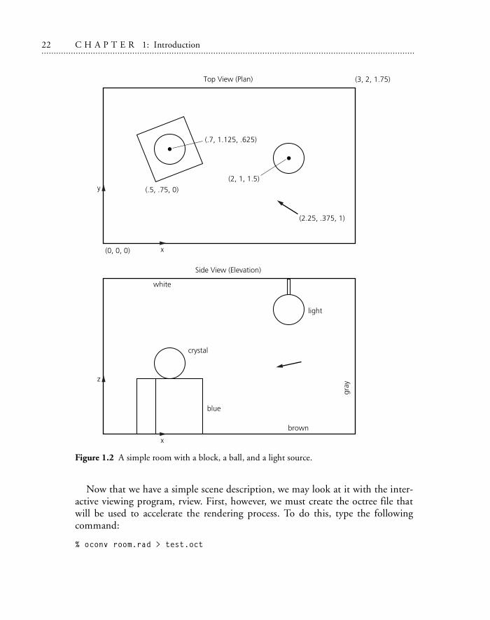
The scene we will be working toward is shown in Figure 1.2. It is usually helpfulto start with a simple drawing showing the coordinate axes and the relative loca-tions of major surfaces.
The minimum input required to get an image is a source of illumination and anobject to reflect light to the “camera.”2 We will begin with two spheres, one emis-sive and the other reflective. First we define the materials, then the spheresthemselves. Actually, the order is important only insofar as each modifier definition(i.e., material) must appear before its first reference. (Consult the Radiance manualfor an explanation of the primitive types and their parameters.) Start your favoritetext editor (vi in this example) to create the following file, called room.rad:
% vi room.rad
## My first scene.#
## The basic primitive format is:#
# modifier TYPE identifier# number_string_arguments [string arguments...]# number_integer_arguments [integer arguments...]# number_real_arguments [string real...]#
2. In fact, a Radiance renderer can be thought of as an invisible camera in a simulated world.
1.3 Scene 0 Tutorial 21. . . . . . . . . . . . . . . . . . . . . . . . . . . . . . . . . . . . . . . . . . . . . . . . . . . . . . . . . . . . . . . . . . . . . . . . . . . . . . . . . . . . . . . . . . . . . . . . . . . . . . . . . . . . .. . . . . . . . . . . . . . . . . . . . . . . . . . . . . . . . . . . . . . . . . . .
# The special modifier "void" means no modifier.# TYPE is one of a finite number of # predefined types, and the meaning of # the arguments following is determined by # this type. (See Radiance Reference
# Manual on the CD-ROM for details). # The identifier may be used as a modifier later # in this file or in files following this one. # All values are separated by white # space (spaces, tabs, newlines).
#
# this is the material for my light source:
void light bright00
3 100 100 100#^ r_radiance g_radiance b_radiance
# this is the material for my test ball:
void plastic red_plastic00
5 .7 .05 .05 .05 .05#^ red green blue specularity roughness
# here is the light source:
bright sphere fixture00
4 2 1 1.5 .125#^ xcent ycent zcent radius
# here is the ball:
red_plastic sphere ball00
4 .7 1.125 .625 .125
22 C H A P T E R 1: Introduction. . . . . . . . . . . . . . . . . . . . . . . . . . . . . . . . . . . . . . . . . . . . . . . . . . . . . . . . . . . . . . . . . . . . . . . . . . . . . . . . . . . . . . . . . . . . . . . . . . . . . . . . . . . .. . . . . . . . . . . . . . . . . . . . . . . . . . . . . . . . . . . . . . . . . . . .
Now that we have a simple scene description, we may look at it with the inter-active viewing program, rview. First, however, we must create the octree file thatwill be used to accelerate the rendering process. To do this, type the followingcommand:
% oconv room.rad > test.oct
Figure 1.2 A simple room with a block, a ball, and a light source.
1.3 Scene 0 Tutorial 23. . . . . . . . . . . . . . . . . . . . . . . . . . . . . . . . . . . . . . . . . . . . . . . . . . . . . . . . . . . . . . . . . . . . . . . . . . . . . . . . . . . . . . . . . . . . . . . . . . . . . . . . . . . . .. . . . . . . . . . . . . . . . . . . . . . . . . . . . . . . . . . . . . . . . . . .
Note that the extension .rad and .oct are not enforced by the program, but aremerely a convenience to aid the user in identifying files later. The command getinfocan be used to get information on the origin of binary (unviewable) files created byRadiance utilities. Try entering the command
% getinfo test.oct
The usefulness of such a function will be apparent when you find yourself with adozen files called test?.pic.
To make an image of our scene, we must select a suitable set of view parameterstelling Radiance where to point its camera. To simplify our example, we will use thesame starting position for all our renderings and change views only once rview isstarted:
% rview -vp 2.25 .375 1 -vd -.25 .125 -.125 -av .5 .5 .5 test.oct
The -vp option gives the view point; the -vd option gives the view direction vec-tor. The -av option specifies the amount of light globally present in the scene,permitting portions of the scene that are not illuminated directly to be visible.Rview has many more options, and their default values may be discovered using
% rview -defaults
You should start to see an image of a red ball forming on your screen. Take thisopportunity to try each of the rview commands, as described in the manual. If youmake a mistake in a view specification, use the last command to get back to whereyou were. It is probably a good idea to save your favorite view using the followingcommand from within rview:
: view default.vf
You can create any number of viewfiles with this command, and retrieve themwith
: last viewfile
If you look around enough, you may even be able to see the light source itself.Unlike those in many rendering programs, the light sources in Radiance are visibleobjects. This illustrates the basic principle that underlies the program, which is thesimulation of physical spaces. Since it is not possible to create an invisible lightsource in reality, there is no reason to do it in simulation.
Still, there is no guarantee that the user will create physically meaningful descrip-tions. For example, we have just floated a red ball next to a light source somewherein intergalactic space. In the interest of making this scene more realistic, let’s enclosethe light and ball in a room by adding the following text to room.rad:
24 C H A P T E R 1: Introduction. . . . . . . . . . . . . . . . . . . . . . . . . . . . . . . . . . . . . . . . . . . . . . . . . . . . . . . . . . . . . . . . . . . . . . . . . . . . . . . . . . . . . . . . . . . . . . . . . . . . . . . . . . . .. . . . . . . . . . . . . . . . . . . . . . . . . . . . . . . . . . . . . . . . . . . .
% vi room.rad# the wall material:
void plastic gray_paint005 .5 .5 .5 0 0
# a box-shaped room:
!genbox gray_paint room 3 2 1.75 -i
The generator program genbox is just a command that produces a Radiancedescription; it is executed when the file is read. It is more convenient than specify-ing the coordinates of four vertices for each of six polygons, and can be changedlater quite easily. (See the genbox manual page on the CD-ROM for furtherdetails.)
You can now look at the modified scene, but remember first to regenerate theoctree:
% oconv room.rad > test.oct% rview -vf default.vf -av .5 .5 .5 test.oct
This is better, but our ball and light source are still floating, which is an unreal-istic condition for most rooms. Let’s put in a box under the table and a rod tosuspend the light from the ceiling:
# a shiny blue box:
void plastic blue_plastic
005 .1 .1 .6 .05 .1
!genbox blue_plastic box .5 .5 .5 \ | xform -rz 15 -t .5 .75 0
# a chrome rod to suspend
# the light from the ceiling:
void metal chrome0
05 .8 .8 .8 .9 0
1.3 Scene 0 Tutorial 25. . . . . . . . . . . . . . . . . . . . . . . . . . . . . . . . . . . . . . . . . . . . . . . . . . . . . . . . . . . . . . . . . . . . . . . . . . . . . . . . . . . . . . . . . . . . . . . . . . . . . . . . . . . . .. . . . . . . . . . . . . . . . . . . . . . . . . . . . . . . . . . . . . . . . . . .
chrome cylinder fixture_support007 2 1 1.5
2 1 1.75 .05
Note that this time the output of genbox was “piped” into another program,xform. (The backslash merely continues the line.) Xform is used to move, scale, androtate Radiance descriptions. Genbox always creates a box in the positive octant of3D space, with one corner at the origin. This was what we wanted for the room,but here we wanted the box moved away from the wall and rotated slightly. First werotated the box 15 degrees about the z-axis (pivoting on the origin), then we trans-lated the corner from the origin to (.5, .75, 0). By no small coincidence, thisposition is directly under our original ball.
After viewing this new arrangement, you can try changing some of the materi-als—here are a few examples:
# solid crystal:
void dielectric crystal
005 .5 .5 .5 1.5 0
# dark brown:
void plastic brown0
05 .2 .1 .1 0 0
# light gray:
void plastic white00
5 .7 .7 .7 0 0
To change the ball from red plastic to the crystal defined above, simply replacered_plastic sphere ball with crystal sphere ball. Note once again that thedefinitions of the new materials must precede any references to them. Changing the
26 C H A P T E R 1: Introduction. . . . . . . . . . . . . . . . . . . . . . . . . . . . . . . . . . . . . . . . . . . . . . . . . . . . . . . . . . . . . . . . . . . . . . . . . . . . . . . . . . . . . . . . . . . . . . . . . . . . . . . . . . . .. . . . . . . . . . . . . . . . . . . . . . . . . . . . . . . . . . . . . . . . . . . .
materials for the floor and ceiling of the room is a little more difficult. Since genboxcreates six rectangles, all using the same material, it is necessary to replace the com-mand with its output before we can make the required changes. To do this, enterthe command directly:
% genbox gray_paint room 3 2 1.75 -i >> room.rad
The double arrow >> causes the output to be appended to the end of the file,rather than overwriting its contents. Now edit the file and change the ceiling mate-rial to white, and the floor material to brown. (Hint: The ceiling is the polygonwhose z coordinates are all high. And don’t forget to remove the original genboxcommand from the file!)
Once you have chosen a nice view, you can generate a high-resolution image inbatch mode using the rpict command:
% rpict -vf myview -av .5 .5 .5 test.oct > test.pic &
[PID]
The ampersand & causes the program to run in the background, so you can logout and go home while the computer continues to work on your picture. Thebracketed number [PID] printed by the C-shell command interpreter is the processID that can be used later to check the progress or kill the program. This numbercan also be determined by the ps command
% ps
The number preceding the rpict command is the process ID. If you want to killthe process, use the command
% kill PID
If you only want to get a progress report without killing the process, use thisform:
% kill -CONT PID
This sends a continue signal to rpict, which causes it to print out the percentageof completion. Note that this is a special feature of rpict and will not work withmost programs. Also note that this works only for the current login session. If youlog on later on a different terminal (or window), rpict will not send the report tothe correct place. It is usually a good idea, therefore, to give rpict an error file argu-ment if it is running a long job:
% rpict -e errfile ...
1.3 Scene 0 Tutorial 27. . . . . . . . . . . . . . . . . . . . . . . . . . . . . . . . . . . . . . . . . . . . . . . . . . . . . . . . . . . . . . . . . . . . . . . . . . . . . . . . . . . . . . . . . . . . . . . . . . . . . . . . . . . . .. . . . . . . . . . . . . . . . . . . . . . . . . . . . . . . . . . . . . . . . . . .
Now sending a continue signal will cause rpict to report to the end of the speci-fied error file. Alternatively, you may use the -t option to generate reportsautomatically at regular intervals. You can check the reports at any time by printingthe file:
% cat errfile
This file will also contain a header and any errors that occurred.
1.3.2 Filtering and Displaying a Picture
If you are running Radiance under X11, you can use the ximage program to displaya rendered picture. Try the following command:
% ximage -e auto test.pic &
The -e auto option tells ximage to perform a histogram exposure adjustment onthe picture, to insure that all areas of the image are visible.
You may notice that the pixels are jagged in the original output from rpict. Thisis because the picture has not been filtered, and filtering is the principal means ofantialiasing in Radiance. The program pfilt performs this task, as well as adjustingthe exposure in a linear fashion, which does not disturb the physical meanings ofthe resultant pixels. Try the following command sequence:
% pfilt -x /2 -y /2 test.pic > testfilt.pic% ximage testfilt.pic &
There is a space between the -x option and its argument, but there is no spacebetween the / character and the 2. This sequence has the effect of reducing our orig-inal image size by one half and bringing it into the appropriate brightness range fordirect display, without the -e auto option.
If you wish to print out a picture or convert it to another format, a number ofconversion utilities are available. For example, the program ra_ps will convert aRadiance picture to a PostScript file, which may then be sent to a printer. Try thecommand
% ra_ps -c testfilt.pic | lpr
(You may have to substitute another command for lpr to send a PostScript jobto your printer.) This will print out the filtered picture on a color PostScript printer.If your printer does not have color, simply leave off the -c option for grayscale out-
28 C H A P T E R 1: Introduction. . . . . . . . . . . . . . . . . . . . . . . . . . . . . . . . . . . . . . . . . . . . . . . . . . . . . . . . . . . . . . . . . . . . . . . . . . . . . . . . . . . . . . . . . . . . . . . . . . . . . . . . . . . .. . . . . . . . . . . . . . . . . . . . . . . . . . . . . . . . . . . . . . . . . . . .
put. If you wish to apply the same kind of dynamic range compression provided bythe -e auto option of ximage, you may use the pcond program as follows:
% pcond testfilt.pic | ra_ps -c | lpr
The pcond program offers many advanced features for reproducing scene visibil-ity, and we recommend that you consult the manual page on the CD-ROM formore details.
1.3.3 Addition of a Window
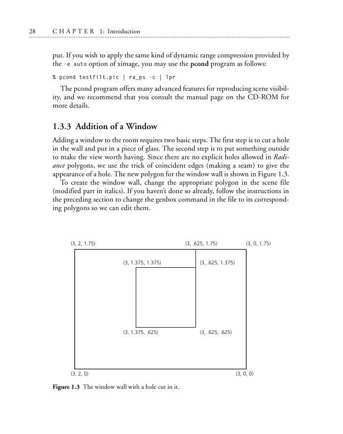
Adding a window to the room requires two basic steps. The first step is to cut a holein the wall and put in a piece of glass. The second step is to put something outsideto make the view worth having. Since there are no explicit holes allowed in Radi-ance polygons, we use the trick of coincident edges (making a seam) to give theappearance of a hole. The new polygon for the window wall is shown in Figure 1.3.
To create the window wall, change the appropriate polygon in the scene file(modified part in italics). If you haven’t done so already, follow the instructions inthe preceding section to change the genbox command in the file to its correspond-ing polygons so we can edit them.
Figure 1.3 The window wall with a hole cut in it.
1.3 Scene 0 Tutorial 29. . . . . . . . . . . . . . . . . . . . . . . . . . . . . . . . . . . . . . . . . . . . . . . . . . . . . . . . . . . . . . . . . . . . . . . . . . . . . . . . . . . . . . . . . . . . . . . . . . . . . . . . . . . . .. . . . . . . . . . . . . . . . . . . . . . . . . . . . . . . . . . . . . . . . . . .
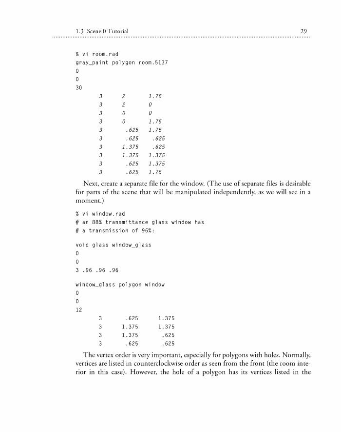
% vi room.radgray_paint polygon room.51370030
3 2 1.75 3 2 0 3 0 0 3 0 1.75 3 .625 1.75
3 .625 .625 3 1.375 .625 3 1.375 1.375 3 .625 1.375 3 .625 1.75
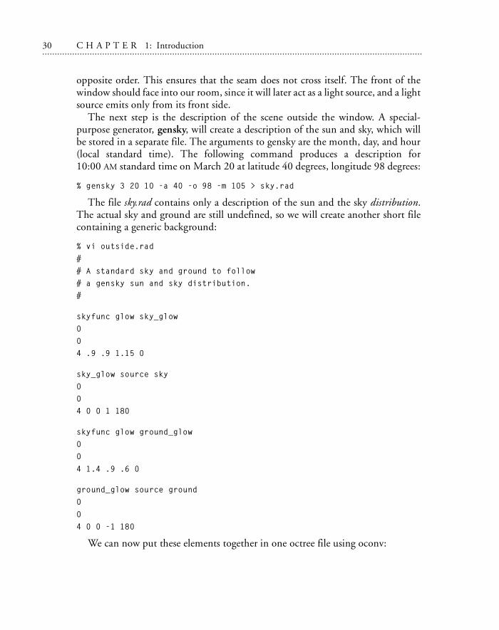
Next, create a separate file for the window. (The use of separate files is desirablefor parts of the scene that will be manipulated independently, as we will see in amoment.)
% vi window.rad# an 88% transmittance glass window has# a transmission of 96%:
void glass window_glass003 .96 .96 .96
window_glass polygon window00
12 3 .625 1.375 3 1.375 1.375 3 1.375 .625 3 .625 .625
The vertex order is very important, especially for polygons with holes. Normally,vertices are listed in counterclockwise order as seen from the front (the room inte-rior in this case). However, the hole of a polygon has its vertices listed in the
30 C H A P T E R 1: Introduction. . . . . . . . . . . . . . . . . . . . . . . . . . . . . . . . . . . . . . . . . . . . . . . . . . . . . . . . . . . . . . . . . . . . . . . . . . . . . . . . . . . . . . . . . . . . . . . . . . . . . . . . . . . .. . . . . . . . . . . . . . . . . . . . . . . . . . . . . . . . . . . . . . . . . . . .
opposite order. This ensures that the seam does not cross itself. The front of thewindow should face into our room, since it will later act as a light source, and a lightsource emits only from its front side.
The next step is the description of the scene outside the window. A special-purpose generator, gensky, will create a description of the sun and sky, which willbe stored in a separate file. The arguments to gensky are the month, day, and hour(local standard time). The following command produces a description for10:00 AM standard time on March 20 at latitude 40 degrees, longitude 98 degrees:
% gensky 3 20 10 -a 40 -o 98 -m 105 > sky.rad
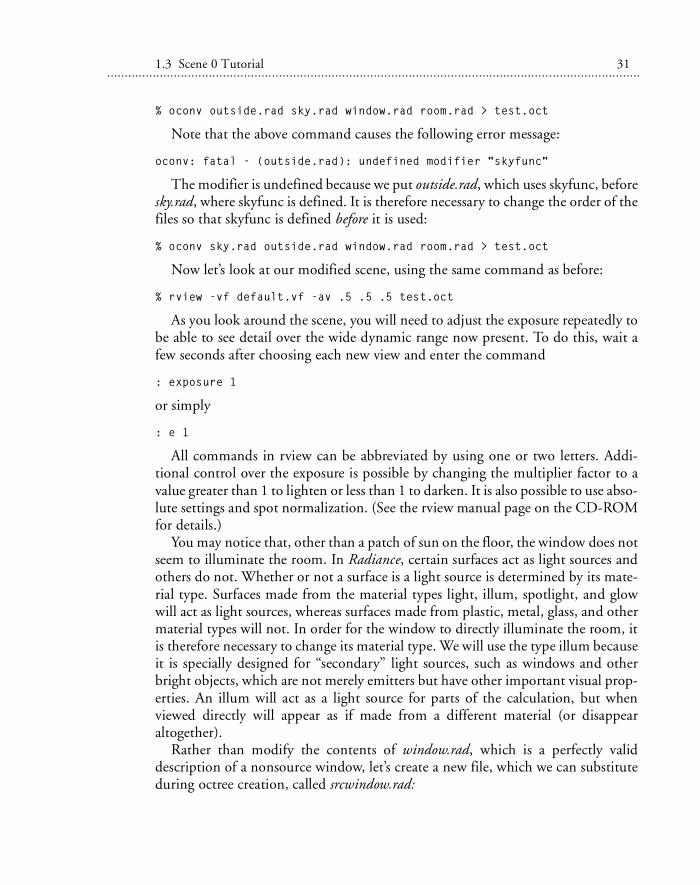
The file sky.rad contains only a description of the sun and the sky distribution.The actual sky and ground are still undefined, so we will create another short filecontaining a generic background:
% vi outside.rad
## A standard sky and ground to follow# a gensky sun and sky distribution.#
skyfunc glow sky_glow004 .9 .9 1.15 0
sky_glow source sky004 0 0 1 180
skyfunc glow ground_glow00
4 1.4 .9 .6 0
ground_glow source ground0
04 0 0 -1 180
We can now put these elements together in one octree file using oconv:
1.3 Scene 0 Tutorial 31. . . . . . . . . . . . . . . . . . . . . . . . . . . . . . . . . . . . . . . . . . . . . . . . . . . . . . . . . . . . . . . . . . . . . . . . . . . . . . . . . . . . . . . . . . . . . . . . . . . . . . . . . . . . .. . . . . . . . . . . . . . . . . . . . . . . . . . . . . . . . . . . . . . . . . . .
% oconv outside.rad sky.rad window.rad room.rad > test.oct
Note that the above command causes the following error message:
oconv: fatal - (outside.rad): undefined modifier "skyfunc"
The modifier is undefined because we put outside.rad, which uses skyfunc, beforesky.rad, where skyfunc is defined. It is therefore necessary to change the order of thefiles so that skyfunc is defined before it is used:
% oconv sky.rad outside.rad window.rad room.rad > test.oct
Now let’s look at our modified scene, using the same command as before:
% rview -vf default.vf -av .5 .5 .5 test.oct
As you look around the scene, you will need to adjust the exposure repeatedly tobe able to see detail over the wide dynamic range now present. To do this, wait afew seconds after choosing each new view and enter the command
: exposure 1
or simply
: e 1
All commands in rview can be abbreviated by using one or two letters. Addi-tional control over the exposure is possible by changing the multiplier factor to avalue greater than 1 to lighten or less than 1 to darken. It is also possible to use abso-lute settings and spot normalization. (See the rview manual page on the CD-ROMfor details.)
You may notice that, other than a patch of sun on the floor, the window does notseem to illuminate the room. In Radiance, certain surfaces act as light sources andothers do not. Whether or not a surface is a light source is determined by its mate-rial type. Surfaces made from the material types light, illum, spotlight, and glowwill act as light sources, whereas surfaces made from plastic, metal, glass, and othermaterial types will not. In order for the window to directly illuminate the room, itis therefore necessary to change its material type. We will use the type illum becauseit is specially designed for “secondary” light sources, such as windows and otherbright objects, which are not merely emitters but have other important visual prop-erties. An illum will act as a light source for parts of the calculation, but whenviewed directly will appear as if made from a different material (or disappearaltogether).
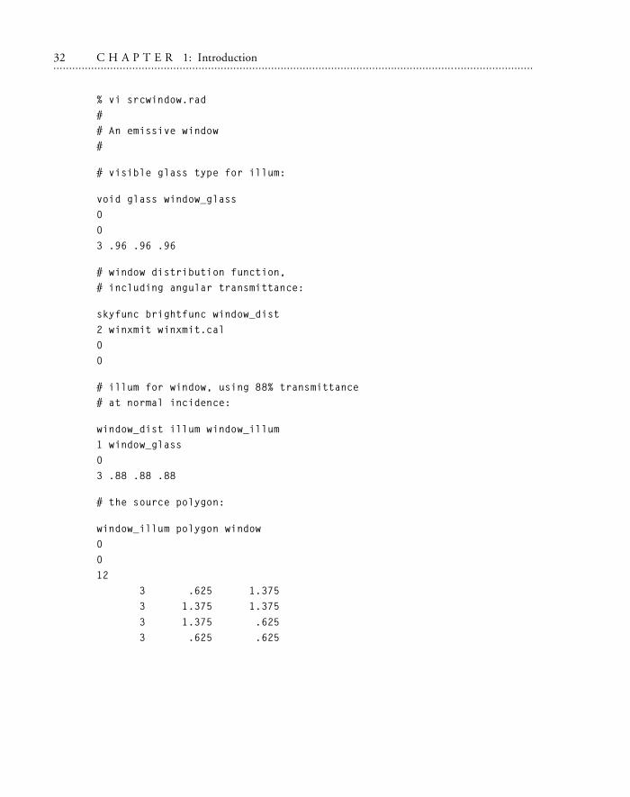
Rather than modify the contents of window.rad, which is a perfectly validdescription of a nonsource window, let’s create a new file, which we can substituteduring octree creation, called srcwindow.rad:
32 C H A P T E R 1: Introduction. . . . . . . . . . . . . . . . . . . . . . . . . . . . . . . . . . . . . . . . . . . . . . . . . . . . . . . . . . . . . . . . . . . . . . . . . . . . . . . . . . . . . . . . . . . . . . . . . . . . . . . . . . . .. . . . . . . . . . . . . . . . . . . . . . . . . . . . . . . . . . . . . . . . . . . .
% vi srcwindow.rad## An emissive window#
# visible glass type for illum:
void glass window_glass003 .96 .96 .96
# window distribution function,# including angular transmittance:
skyfunc brightfunc window_dist2 winxmit winxmit.cal00
# illum for window, using 88% transmittance# at normal incidence:
window_dist illum window_illum1 window_glass03 .88 .88 .88
# the source polygon:
window_illum polygon window0012 3 .625 1.375 3 1.375 1.375
3 1.375 .625 3 .625 .625
1.3 Scene 0 Tutorial 33. . . . . . . . . . . . . . . . . . . . . . . . . . . . . . . . . . . . . . . . . . . . . . . . . . . . . . . . . . . . . . . . . . . . . . . . . . . . . . . . . . . . . . . . . . . . . . . . . . . . . . . . . . . . .. . . . . . . . . . . . . . . . . . . . . . . . . . . . . . . . . . . . . . . . . . .
You should notice a couple of things in this file. The first definition is the normalglass type, window_glass, which is used for the alternate material for the illumwindow_illum. Next is the window distribution function, which is the sky distribu-tion modified by angular transmittance of glass defined in winxmit.cal. Finallycomes the illum itself, which is the secondary source material for the window.
To look at the scene, simply substitute srcwindow.rad for window.rad in the pre-vious oconv command, thus:
% oconv sky.rad outside.rad srcwindow.rad room.rad > test.oct
You can look at the room at different times by changing the gensky commandused to create sky.rad and regenerating the octree. (Although the octree does notstrictly need to be recreated for every change to the input files, it is good to get intothe habit until the exceptions are well understood.)
1.3.4 Automating the Rendering Process
Until now, we have been using the individual Radiance programs directly to createoctrees and perform renderings. By creating a control file, we can leave the detailsof running the right commands with the right options in the right order to theRadiance executive program, rad. Similar to the UNIX make command, rad paysattention to file-modified times in deciding whether or not the octree needs to berebuilt or other files need to be updated. Rad also has a lot of built-in “smarts”about Radiance rendering options, and improves rendering time and quality byoptimizing parameter values based on qualitative information in the control fileinstead of relying on defaults. Finally, rad can quickly find reasonable views withoutforcing you to think too much in terms of xyz coordinate positions and directions.
A control file contains a list of variable assignments, generally one per line. Somevariables can be assigned multiple values; these variables are given in lowercase.Variables that can have only a single value are given in uppercase. Here is a minimalcontrol file, which we’ll call simple.rif:
# My first "rad input file"
############################ First, we must specify the "ZONE" for this # scene, which gives the x, y, and z dimensions # of our space. The "I" stands for # "interior", since we are interested in # the inside of this space:
34 C H A P T E R 1: Introduction. . . . . . . . . . . . . . . . . . . . . . . . . . . . . . . . . . . . . . . . . . . . . . . . . . . . . . . . . . . . . . . . . . . . . . . . . . . . . . . . . . . . . . . . . . . . . . . . . . . . . . . . . . . .. . . . . . . . . . . . . . . . . . . . . . . . . . . . . . . . . . . . . . . . . . . .
ZONE= I 0 3 0 2 0 1.75# xmin xmax ymin ymax zmin zmax
############################ Next, we need to tell rad what scene input # files to use and in what order. For this, we # use the lowercase variable "scene", which# allows multiple values. Literally, all
# the values are concatenated by rad, in the# order we give them, on the oconv command line:
scene= sky.rad outside.rad
scene= srcwindow.radscene= room.rad
###########################
# Technically, we could stop here and let# rad figure out the rest, but it is very# useful to also give an exposure value that# is appropriate for this scene. We can discover# this value from within rview using the "e ="# command once we have found the exposure level
# we like. For the interior of our space# under these particular lighting conditions,# an exposure value of 0.5 works well:
EXPOSURE= 0.5# This could as well have been "-1" (f-stops)
Once we have this simple input file, we can start using rad to run our commandsfor us, as in this example:
% rad -o x11 simple.rif
The -o option tells rad to run rview under X11 instead of creating pictures (thedefault action) using rpict. If you are using a different window system, then youshould substitute the appropriate driver module for x11. To discover what modulesare available with your version of rview, type
% rview -devices
Once started, rad shows us the commands as it executes them: first oconv, thenrview.
1.3 Scene 0 Tutorial 35. . . . . . . . . . . . . . . . . . . . . . . . . . . . . . . . . . . . . . . . . . . . . . . . . . . . . . . . . . . . . . . . . . . . . . . . . . . . . . . . . . . . . . . . . . . . . . . . . . . . . . . . . . . . .. . . . . . . . . . . . . . . . . . . . . . . . . . . . . . . . . . . . . . . . . . .
Since we didn’t specify a view in our control file, rad picks one for us, which itcalls X. This is one of the standard views, and it means “from the maximum x posi-tion.” As another example, the view yZ would mean “from the minimum y andmaximum z position.” The actual positions are determined from the ZONE specifi-cation, and are just inside the boundaries for an interior zone, and well outside theboundaries for an exterior zone. (Please take a few moments at this time to consultthe rad manual page on the CD-ROM, under “view,” to learn more about thesestandard identifiers.) We could have selected a different standard view on the com-mand line using the -v option, as in this example:
% rad -o x11 -v Zl simple.rif
This specification gives us a parallel projection from Z, the maximum z position(i.e., a plan view). Rather than executing another rad command, we can get thesame view functionality from within rview using the L command. (This is a single-letter command, corresponding roughly to the “last” command for retrieving viewsfrom files, explained earlier.) This command actually consults rad using the currentcontrol file to compute the desired view. The complementary V command appendsthe current view to the end of the control file for later access and batch rendering.For example, you can put the default viewpoint into your control file using therview commands:
: last default.vf
followed by
: V def
(Shorter view names are better because they end up being part of the picture filename, which can get quite long.) Move around in rview to find a few different viewsyou like, and save them (with sensible names) to the control file using the V com-mand. If you make a mistake and save a view you later decide you dislike, you mustedit the control file and manually remove the corresponding line.
Looking through the rad manual page, you will notice that there are many vari-ables we have left unspecified in our simple control file. To discover what valuesthese variables are given, we can use the -e option (together with -n and -s to avoidactually doing anything):
% rad -e -n -s simple.rif
Some of these default values do not make sense for our scene. In particular, theVARIABILITY is not Low, because there is sunlight entering our space. We should alsochange the DETAIL variable from Medium to Low because our space is really quite sim-ple. Once we are satisfied with the geometry in our scene, we will probably want to
36 C H A P T E R 1: Introduction. . . . . . . . . . . . . . . . . . . . . . . . . . . . . . . . . . . . . . . . . . . . . . . . . . . . . . . . . . . . . . . . . . . . . . . . . . . . . . . . . . . . . . . . . . . . . . . . . . . . . . . . . . . .. . . . . . . . . . . . . . . . . . . . . . . . . . . . . . . . . . . . . . . . . . . .
raise the quality of output from the default value of Low. It is also a good idea tospecify an ambient file name, so that renderings requiring an indirect calculationwill be more efficient. We can add the following lines to simple.rif to correct theseproblems:
# We can abbreviate VARIABILITY with 3 lettersVAR= High
# Anything starting with upper or lower ‘L’ is LOWDET= L# Go for a medium-quality resultQUAL= Med
# The file in which to store indirect valuesAMB= simple.amb
If we want to create picture files for the selected views in batch mode, we can runrad in the background, as follows:
% rad simple.rif &
This will, of course, echo the commands before they are executed, which may beundesirable for a background job. So we can use the “silent” mode instead:
% rad -s simple.rif &
Better still, we may want rad to record the commands executed, along with anyerror reports or other messages, to an error file:
% rad simple.rif >& errs &
The >& notation is recognized by the C-shell to mean “redirect both the standardoutput and the standard error to a file.” Bourne shell users should use the followingform instead:
% rad simple.rif > errs 2>&1 &
1.3.5 Outside Geometry
If the exterior of a space is not approximated well by an infinitely distant sky andground, we can add a better description to calculate a more accurate window out-put distribution as well as a better view outside the window. Let’s add a groundplane and a nearby building to the outside.rad file we created earlier and call thisnew file outside2.rad:
1.3 Scene 0 Tutorial 37. . . . . . . . . . . . . . . . . . . . . . . . . . . . . . . . . . . . . . . . . . . . . . . . . . . . . . . . . . . . . . . . . . . . . . . . . . . . . . . . . . . . . . . . . . . . . . . . . . . . . . . . . . . . .. . . . . . . . . . . . . . . . . . . . . . . . . . . . . . . . . . . . . . . . . . .
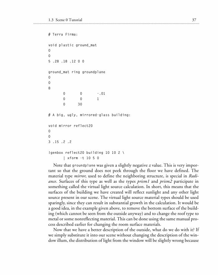
# Terra Firma:
void plastic ground_mat00
5 .28 .18 .12 0 0
ground_mat ring groundplane00
8 0 0 -.01 0 0 1 0 30
# A big, ugly, mirrored-glass building:
void mirror reflect20003 .15 .2 .2
!genbox reflect20 building 10 10 2 \ | xform -t 10 5 0
Note that groundplane was given a slightly negative z value. This is very impor-tant so that the ground does not peek through the floor we have defined. Thematerial type mirror, used to define the neighboring structure, is special in Radi-ance. Surfaces of this type as well as the types prism1 and prism2 participate insomething called the virtual light source calculation. In short, this means that thesurfaces of the building we have created will reflect sunlight and any other lightsource present in our scene. The virtual light source material types should be usedsparingly, since they can result in substantial growth in the calculation. It would bea good idea, in the example given above, to remove the bottom surface of the build-ing (which cannot be seen from the outside anyway) and to change the roof type tometal or some nonreflecting material. This can be done using the same manual pro-cess described earlier for changing the room surface materials.
Now that we have a better description of the outside, what do we do with it? Ifwe simply substitute it into our scene without changing the description of the win-dow illum, the distribution of light from the window will be slightly wrong because
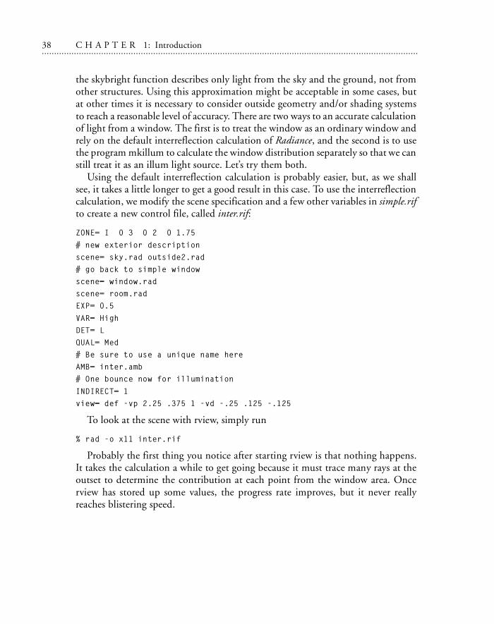
38 C H A P T E R 1: Introduction. . . . . . . . . . . . . . . . . . . . . . . . . . . . . . . . . . . . . . . . . . . . . . . . . . . . . . . . . . . . . . . . . . . . . . . . . . . . . . . . . . . . . . . . . . . . . . . . . . . . . . . . . . . .. . . . . . . . . . . . . . . . . . . . . . . . . . . . . . . . . . . . . . . . . . . .
the skybright function describes only light from the sky and the ground, not fromother structures. Using this approximation might be acceptable in some cases, butat other times it is necessary to consider outside geometry and/or shading systemsto reach a reasonable level of accuracy. There are two ways to an accurate calculationof light from a window. The first is to treat the window as an ordinary window andrely on the default interreflection calculation of Radiance, and the second is to usethe program mkillum to calculate the window distribution separately so that we canstill treat it as an illum light source. Let’s try them both.
Using the default interreflection calculation is probably easier, but, as we shallsee, it takes a little longer to get a good result in this case. To use the interreflectioncalculation, we modify the scene specification and a few other variables in simple.rifto create a new control file, called inter.rif:
ZONE= I 0 3 0 2 0 1.75
# new exterior descriptionscene= sky.rad outside2.rad# go back to simple windowscene= window.radscene= room.radEXP= 0.5
VAR= HighDET= LQUAL= Med# Be sure to use a unique name hereAMB= inter.amb# One bounce now for illumination
INDIRECT= 1view= def -vp 2.25 .375 1 -vd -.25 .125 -.125
To look at the scene with rview, simply run
% rad -o x11 inter.rif
Probably the first thing you notice after starting rview is that nothing happens.It takes the calculation a while to get going because it must trace many rays at theoutset to determine the contribution at each point from the window area. Oncerview has stored up some values, the progress rate improves, but it never reallyreaches blistering speed.
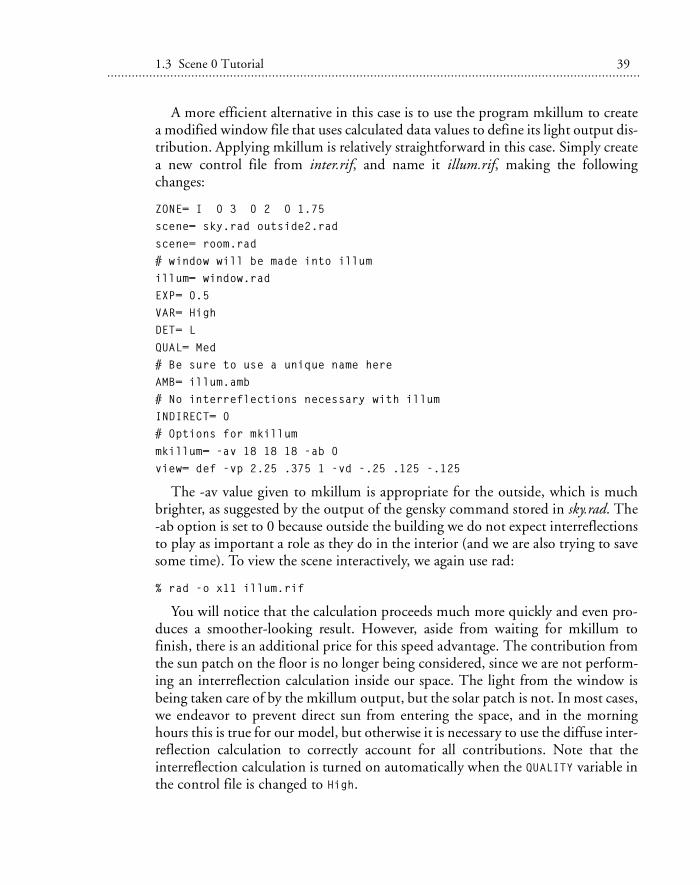
1.3 Scene 0 Tutorial 39. . . . . . . . . . . . . . . . . . . . . . . . . . . . . . . . . . . . . . . . . . . . . . . . . . . . . . . . . . . . . . . . . . . . . . . . . . . . . . . . . . . . . . . . . . . . . . . . . . . . . . . . . . . . .. . . . . . . . . . . . . . . . . . . . . . . . . . . . . . . . . . . . . . . . . . .
A more efficient alternative in this case is to use the program mkillum to createa modified window file that uses calculated data values to define its light output dis-tribution. Applying mkillum is relatively straightforward in this case. Simply createa new control file from inter.rif, and name it illum.rif, making the followingchanges:
ZONE= I 0 3 0 2 0 1.75scene= sky.rad outside2.rad
scene= room.rad# window will be made into illumillum= window.radEXP= 0.5 VAR= HighDET= L
QUAL= Med# Be sure to use a unique name hereAMB= illum.amb# No interreflections necessary with illumINDIRECT= 0# Options for mkillum
mkillum= -av 18 18 18 -ab 0view= def -vp 2.25 .375 1 -vd -.25 .125 -.125
The -av value given to mkillum is appropriate for the outside, which is muchbrighter, as suggested by the output of the gensky command stored in sky.rad. The-ab option is set to 0 because outside the building we do not expect interreflectionsto play as important a role as they do in the interior (and we are also trying to savesome time). To view the scene interactively, we again use rad:
% rad -o x11 illum.rif
You will notice that the calculation proceeds much more quickly and even pro-duces a smoother-looking result. However, aside from waiting for mkillum tofinish, there is an additional price for this speed advantage. The contribution fromthe sun patch on the floor is no longer being considered, since we are not perform-ing an interreflection calculation inside our space. The light from the window isbeing taken care of by the mkillum output, but the solar patch is not. In most cases,we endeavor to prevent direct sun from entering the space, and in the morninghours this is true for our model, but otherwise it is necessary to use the diffuse inter-reflection calculation to correctly account for all contributions. Note that theinterreflection calculation is turned on automatically when the QUALITY variable inthe control file is changed to High.
40 C H A P T E R 1: Introduction. . . . . . . . . . . . . . . . . . . . . . . . . . . . . . . . . . . . . . . . . . . . . . . . . . . . . . . . . . . . . . . . . . . . . . . . . . . . . . . . . . . . . . . . . . . . . . . . . . . . . . . . . . . .. . . . . . . . . . . . . . . . . . . . . . . . . . . . . . . . . . . . . . . . . . . .
1.4 ConclusionBy now, you should have a fair idea of what Radiance has to offer and should evenhave gained some insight into the way it all works together. If the Scene 0 tutorialleft you with some unanswered questions, we recommend that you continue withthe Scene 1 tutorial in Chapter 2. After that, the Scene 2 tutorial in Chapter 3 pro-vides some very interesting surprises. Chapter 4 continues with examples of“scripting” in Radiance. Part II, Applications (Chapters 5 through 9), gives applica-tion-specific advice and case studies. Part III, Calculation Methods (Chapters 10through 15), goes into graphic detail to describe what exactly is going on insideRadiance; this is important to the advanced user who wants greater understandingand control, as well as to the graphics researcher who wants to know.
Radiance has been used to visualize the lighting of homes, apartments, hotels,offices, libraries, churches, theaters, museums, stadiums, roads, tunnels, bridges,airports, jets, and space shuttles. It has answered questions about light levels, esthet-ics, daylight utilization, visual comfort and visibility, energy savings potential, solarpanel coverage, computer vision, and circumstances surrounding accidents. If youcan imagine it, and you want to know what it will really look like, Radiance is thetool that can show you.