Embed Size (px)
Citation preview
Reprinted from Lab on a Chip
Lab on a Chip
PAPER
Cite this: Lab Chip, 2017, 17, 1069
Received 6th December 2016,Accepted 14th February 2017
DOI: 10.1039/c6lc01500j
rsc.li/loc
Electrowetting without external voltage usingpaint-on electrodes†
Collin B. Eaker,a Ishan D. Joshipura,a Logan R. Maxwell,a
Jason Heikenfeldb and Michael D. Dickey*a
Electrowetting uses voltage to manipulate small volumes of fluid for applications including lab-on-a-chip
and optical devices. To avoid electrochemical reactions, a dielectric often separates the fluid from the
electrode, which has the undesired effect of adding processing steps while increasing the voltage neces-
sary for electrowetting. We present a new method to dramatically reduce the complexity of electrode and
dielectric fabrication while enabling multiple performance advances. This method relies on a self-oxidizing
paint-on liquid-metal electrode that can be fabricated in minutes on rigid, rough, or even elastic substrates,
enabling low operation voltages (<1 V), and self-healing upon dielectric breakdown. Furthermore, due to
the non-negligible ‘potential of zero charge’, electrowetting occurs by simply short circuiting the
electrodes. This work opens up new application spaces for electrowetting (e.g. stretchable substrates, soft
and injectable electrodes) while achieving large changes in contact angle without the need for an external
power supply.
Introduction
Electrowetting is a technique used to manipulate liquid dropson a substrate.1,2 It is useful for microfluidic applications in-cluding liquid lenses,3 displays,4,5 and miniature bioassays.6,7
Unlike electrocapillarity,8 electrowetting is driven by anelectromechanical force and does not involve a change ininterfacial tension. Applying a potential to the fluid of interest(often water) relative to an electrically insulated counterelectrode generates the required electrical charge. The electri-cal insulation (dielectric) prevents Faradaic electrochemicalreactions from occurring in the liquid (e.g., electrolysis of wa-ter). This configuration is called electrowetting-on-dielectric(EWOD) and is the most common electrowetting techniquefor actuating fluids. As applied voltage is increased, the liquidchanges its apparent contact angle to lower its capacitive en-ergy. An ideal EWOD system should achieve maximumchanges in contact angle with minimal applied voltage.
However, fabricating an ideal electrode for EWOD is typi-cally a challenging process, especially when low voltage oper-ation (<15 V) is desired. The dielectric coated atop a conduc-tive metal film or doped Si wafer9 is often achieved via
thermal oxidation, sputtering, thermal evaporation, or atomiclayer deposition. An ideal dielectric exhibits a large electricalcapacitance and is free of pin holes to prevent electricalshorts through the insulator. Electrowetting dielectrics arecommonly hundreds of nanometers to several microns thickto ensure sufficient insulation between the liquid and theelectrode.10 However, thicker dielectrics necessitate largervoltages. Furthermore, reducing the dielectric thickness is of-ten insufficient, because the required voltage decreases onlyas the square root of the thickness.11 Some clever resolutionshave been developed to mitigate dielectric breakdown, in-cluding multilayers of dielectrics,11 self-healing dielectrics,12
and utilization of two immiscible electrolytes.13
Here, we demonstrate a unique approach for creating self-healing, low-voltage, battery-free, and even stretchableelectrowetting systems. In this work, an electrode composedof eutectic gallium indium (EGaIn, 75% Ga, 25% In byweight)14 or pure gallium can be simply painted on a sub-strate (e.g. glass) at room temperature. Due to the low melt-ing point (∼15.5 °C) of EGaIn, the metal is liquid at roomtemperature and forms a thin (∼1–3 nm)15,16 passivating ox-ide layer. This oxide forms spontaneously in the presence ofoxygen and serves to mechanically stabilize the liquid metalin the shape of a film. This work takes advantage of the thin,self-forming oxide as a dielectric for electrowetting.
Using an EGaIn electrode is a simple approach that solvesnumerous electrowetting challenges: (i) unlike traditionalEWOD dielectrics, EGaIn can be applied to a surface quickly,at room temperature, and without vacuum processing. This
Lab Chip, 2017, 17, 1069–1075 | 1069This journal is © The Royal Society of Chemistry 2017
aDepartment of Chemical and Biomolecular Engineering, North Carolina State
University, Raleigh, NC 27695-7905, USA. E-mail: [email protected] of Electrical Engineering and Computing Systems, University of
Cincinnati, Cincinnati, OH 45221-0030, USA
† Electronic supplementary information (ESI) available. See DOI: 10.1039/c6lc01500j
Publ
ishe
d on
14
Febr
uary
201
7. D
ownl
oade
d by
UN
IVE
RSI
TY
OF
CIN
CIN
NA
TI
on 1
5/03
/201
7 12
:06:
03.
View Article OnlineView Journal | View Issue
Reprinted from Lab on a Chip
1070 | Lab Chip, 2017, 17, 1069–1075 This journal is © The Royal Society of Chemistry 2017
process is shown in Fig. 1. (ii) As a liquid, EGaIn conforms toboth non-planar and stretchable substrates. (iii) The Ga oxideon EGaIn can support self-assembled lipid bilayers17,18 thatenable large contact angle changes (>100°) for water by ap-plying small voltages (100s of mV). (iv) The anodic nature ofthe oxide and the self-assembly of the lipid bilayer allows thedielectric layer to self-heal upon breakdown.12 (v) Perhapsmost interestingly, the small voltages required to inducechanges in contact angle in this system reveal the effects ofthe so-called ‘potential of zero charge’, which allows signifi-cant electrowetting to occur simply by shorting the electrodeswithout the need for an external voltage.
The potential of zero charge, VPZC, is the electric potentialat which the plot of apparent contact angle versus potential(i.e. the electrowetting curve) reaches a maximum. It can beunderstood by considering the Lippmann–Young equation,1
which models the contact angle change in response to volt-age across an electrowetting interface as shown in eqn (1),
(1)
where θ is the contact angle of the liquid as a function of ap-plied voltage (V), θY is the Young's angle (i.e., the angle in theabsence of applied voltage), C is the capacitance of the dielec-tric normalized by area in contact with the liquid, V is the ap-plied voltage, VPZC is the potential of zero charge, and γwo isthe interfacial tension between the two liquids (e.g. water andoil). The VPZC is a function of surface potential, electrolytecomposition, and the composition of the top and bottomelectrodes. According to eqn (1), the VPZC causes the electro-wetting curve to be centered away from zero volts.19 In mostelectrowetting systems, however, inducing changes in contactangle requires application of tens20 to hundreds21 of volts.These voltages are significantly larger than the VPZC (<1 V);therefore, the electrowetting curve often appears to center at
zero volts. Thus, in practice, the VPZC is neither experimen-tally significant nor discernable.
In the system described here, the voltages needed to in-duce electrowetting are extremely low (similar in magnitudeto the VPZC) due to the very large capacitance (arising fromthe thin dielectric) and the low γwo (arising from the use ofsurfactants). Furthermore, the materials of construction ren-der a large VPZC. Consequently, significant electrowetting oc-curs by simply short-circuiting the electrodes without an ex-ternal potential present. Stated differently, eqn (1) evaluatedat V = 0 results in a significant change in contact angle sinceVPZC is non-negligible. Consequently (and in contrast to con-ventional EWOD), increasing the potential relative to 0 V in-creases the contact angle of the liquid droplet; thus, it is pos-sible to electro-dewet a droplet under these circumstances.
In this paper, we outline the fabrication of these EGaInelectrodes, characterize their electrowetting behavior, de-scribe the wetting of drops of water when short-circuited withthe electrode, and demonstrate the robustness of the electro-wetting while stretching of the underlying substrate. Theseunconventional materials are compatible with microfluidicsystems, in the form of injectable electrodes,22,23 potentiallyleading to new applications.
Methods and materialsSubstrate fabrication
We fabricated the electrodes by first constructing a spreadertool (similar to a slot die with a gap of 50 μm) out of poly-methylmethacrylate (PMMA) using a laser cutter. Draggingthe spreader along the length of the 1 × 3″ glass slideestablished a thin and shiny film from a 100 μL drop ofEGaIn. The film was spread across a piece of copper tape onthe substrate, to form an electrical connection. This methodwas also used for the gallium electrode, with the galliumplaced in a freezer until it solidified. For the rough film, a 20μL drop was brushed across the glass surface with a cloth
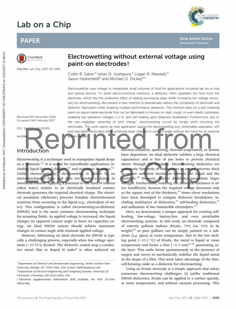
Fig. 1 Preparation of the ‘paint on’ liquid metal electrodes for low-voltage electrowetting. (a–c) 100 μL drop of EGaIn is placed on a glass sub-strate and spread as a film across the surface. (d and e) A DI H2O/1 wt% SDS drop is submerged in dodecane/0.2 wt% sorbitan trioleate solutionand voltage is applied across a top electrode (a stainless steel dispensing needle) and the EGaIn layer. (f) DC electrowetting curve of DI H2O andH2O/1 wt% SDS, including theoretical curves. Error bars represent s.d.
Lab on a ChipPaper
Publ
ishe
d on
14
Febr
uary
201
7. D
ownl
oade
d by
UN
IVE
RSI
TY
OF
CIN
CIN
NA
TI
on 1
5/03
/201
7 12
:06:
03.
View Article Online

Reprinted from Lab on a Chip
Lab Chip, 2017, 17, 1069–1075 | 1071This journal is © The Royal Society of Chemistry 2017
until a continuous film was established across the entiresurface.
DC electrowetting
The contact angle of the water drop was recorded at equilib-rium upon applying a DC voltage. A contact angle goniometer(manufactured by First Ten Angstroms) recorded the con-tact angle of the droplet simultaneously. De-ionized water ora solution of water and 1 wt% sodium dodecyl sulfate weredispensed within the oil with a 30 gauge stainless steel sy-ringe needle. Electrical experiments were performed withAgilent E3612A power source. Electrical connections weremade to the copper tape on the substrate, and to the syringeneedle. The positive terminal of the power source wasconnected to the stainless steel syringe tip. Meanwhile, thenegative terminal was connected to the Cu tape. The negativeterminal was also grounded to the source meter. A Flukemultimeter connected in parallel to the Agilent power sourcewas used to verify the applied voltage. Potential was appliedfrom −1.40 V to −0.30 V for the DI water, and −1.30 V to −0.45V for the SDS/water, in 50 mV increments. The results shownin Fig. 2 represent the average contact angle at the respectivevoltage from three trials. The error bars show the standarddeviation of contact angle from the three trials.
Beyond −1.1 V, the water droplet cannot achieve an equi-librium contact angle due to dielectric breakdown. In thebreakdown regime, the water droplet moves spatially, whichresults in asymmetric contact angle between left and rightside of droplet. The asymmetry of the drop is the cause forhigh standard deviation of contact angle beyond −1.1 V.
AC electrowetting
All AC electrowetting experiments use a two-electrode config-uration. A Gamry Reference 600 potentiostat applied a −800mV DC offset with respect to the stainless steel counter-electrode at 100 Hz (sine waveform). The experiments were
performed from 0 mV RMS to 800 mV RMS, in 50 mV incre-ments; they were also performed in both directions, to testfor hysteresis. The potential was applied on for at least oneminute to allow the contact angle to reach equilibrium.
Stretchable electrowetting
The stretchable substrates were prepared in the same manneras the glass slides. The EGaIn was spread across a 3 cm ×1.25 cm piece of Ecoflex. The Ecoflex was then stretched to 6cm, and clipped down to a glass slide to hold the strain inplace.
Wetting by short-circuit
The experiments were performed by directly connecting thecopper tape attached to the substrate and the stainless steelsyringe needle.
Variable electrodes
23 gauge polypropylene syringe tips were used to dispense DIwater. The top electrode material was inserted into the plasticabove the syringe tip through a hole drilled into the wall ofthe syringe tip (to make a connection to the water), andconnected to the potentiostat. EGaIn and gallium wereinjected into Tygon® tubing and then sealed above the tip inthe same manner. Linear sweep voltammetry was performedusing a Gamry Reference 600 potentiostat. The potential wasthen swept at 1 mV s−1 from −1.5 V to −0.2 V with respect tothe counter-electrode for the case of platinum, stainless steel,and copper. For gallium and EGaIn, the potential was sweptfrom −0.5 V to 0.5 V with respect to the counter-electrode,and the resulting contact angle and current were measured.This method was then repeated, with a reference electrode,along with the counter-electrode. To fabricate the referenceelectrode, a silver wire was inserted into Tygon tubing thatwas filled with an agar hydrogel. The hydrogel was made byplacing 2 wt% agar into a solution of saturated silver chloride
Fig. 2 Electrowetting on a stretchable substrate. (a) AC electrowetting curve on EGaIn, with both no strain and 100% strain of the underlyingsubstrate. (b) Minimum reversible contact angle achieved (7°) with AC electrowetting at −800 mV RMS applied. (c) Photographs of i) EGaIn film ona substrate made of silicone elastomer. ii) Liquid metal conforms to the elastomer and elongates when the substrate is stretched.
Lab on a Chip Paper
Publ
ishe
d on
14
Febr
uary
201
7. D
ownl
oade
d by
UN
IVE
RSI
TY
OF
CIN
CIN
NA
TI
on 1
5/03
/201
7 12
:06:
03.
View Article Online

Reprinted from Lab on a Chip
1072 | Lab Chip, 2017, 17, 1069–1075 This journal is © The Royal Society of Chemistry 2017
in 3.5 M potassium chloride, heating the solution, and theninjecting into the tubing. Once the reference and counter-electrode were inserted, a linear sweep was performed at 1mV s−1 for each metal, from −1.5 V to −0.2 V with respect tothe Ag/AgCl reference. From this, the contact angle and cur-rent were simultaneously measured.
Results
We fabricate the electrodes by dragging a 100 μL droplet ofEGaIn along the length of a glass slide using a custom-builtslot die coater. This process establishes a thin and shiny filmof EGaIn, as seen in Fig. 1a–c. A strip of copper tape underthe liquid metal forms an electrical connection. The entireapparatus rests on the stage of a contact angle goniometer(Fig. 1d).
The liquid metal electrode supports a droplet of de-ionized water (DI H2O) with 1 wt% sodium dodecyl sulfate(SDS). A stainless-steel electrode connects to the top of thewater droplet, as shown in Fig. 1e. The entire system is sub-merged in a solution of dodecane containing 0.2 wt%sorbitan trioleate (a non-ionic surfactant). Surfactants are typ-ically used in electrowetting to lower the energetic penalty as-sociated with increasing meniscus surface area (spreading,wetting) and therefore increase the responsiveness of the liq-uid to voltage. Previous studies show that sorbitan trioleateforms a lipid bilayer between the drop of water and sub-strate,17 which is evidenced here by the lack of wetting be-tween the liquid and substrate. In this case, the lipid bilayerlowers the interfacial surface tension of the SDS/water solu-tion to a very low level of ∼0.2 mN m−1, based on pendantdrop analysis. Due to the thin dielectric utilized in this sys-tem, small voltages were utilized to avoid dielectric break-down; this low interfacial tension allows large contact anglechanges to occur at these voltages.
The experimental configuration in Fig. 1 is representativeof a typical EWOD system. Here, the dielectric is the galliumoxide that forms spontaneously on the surface of the liquidmetal along with the lipid bilayer that self-assembles on theoxide (with a total thickness of approximately 3–5 nm, ESI†).The native oxide on the liquid metal is hydrophilic (DI watercontact angles ∼5–10 degrees). It is possible to add a hydro-phobic coating (e.g. Fluoropel) to the oxide surface to allowits use in air, but that coating decreases the capacitance andelectrowetting requires larger voltages. The oil/surfactant mix-ture in this system is therefore important because it rendersthe oxide surface hydrophobic and decreases the interfacialtension of the water. Fig. 1f shows the electrowetting curvefor an applied DC potential. These curves show dramatic con-tact angle changes (70–80° changes over 400 mV for a solu-tion of DI H2O/1 wt% SDS), with the parabolic shapes indicat-ing classic electrowetting behavior. Importantly, the curvereaches a maximum away from zero volts (approximately−900 mV) for both fluids. This maximum of contact angleidentifies the potential of zero charge (VPZC). The largestchanges in contact angle occurs at −1.3 V and −0.5 V, which
are approximately 0.4 V from the VPZC. At these terminal po-tentials, satellite droplets emerge from the contact line of wa-ter and lipid bilayer, which has also been observed at occur-rence of electrowetting saturation.24 These values also agreewell with the theoretical curves given by eqn (1), plottedusing the experimentally measured capacitance (ESI†). Ineach case, the droplets showed full reversibility, dewettingfrom the substrate and beading up into a spherical shapeupon removal of the potential. The wetting behavior con-tinues to be fully switchable even after dielectric breakdownoccurs. This recovery is due to the self-healing nature of theoxide layer of the liquid metal and subsequent reassembly ofthe lipid bilayer.
AC potentials are known to increase the stability of thecontact line in electrowetting by preventing either chargetrapping or degradation,25,26 and thereby improve reproduc-ibility and minimize dielectric breakdown. In addition to ex-ploring the DC behavior, we also employed an AC potentialwith a −800 mV DC offset to account for the potential of zerocharge. This offset centers the electrowetting curve aboutzero volts, as shown in the electrowetting curve plotted inFig. 2a. The contact angle shows a substantial decrease(∼130° change) with the application of only 700 mV RMS.Furthermore, we observe contact angle saturation27 at an av-erage value of 20° (Movie S1†) with a minimum observedvalue of 7°, as shown in Fig. 2b. The low value of saturationis desirable, as saturation occurs near 60–80° for traditionalaqueous EWOD systems,28 with lower values (15–30°)29 beingobserved with ionic liquids. As expected, the AC electro-wetting results show significantly less variance than the DCelectrowetting, and the contact line remained stable over theduration of the tests (up to several hours), with no observedsatellite droplets. In addition, sequentially increasing and de-creasing the amplitude of the AC potential provided no signsof contact angle hysteresis in the system (ESI†). The lack ofhysteresis with use of AC potential is consistent with resultsboth theoretically and experimentally proven by Mugele andcolleagues.30
The formation of the oxide layer on the liquid metal sur-face provides several advantages that have been utilized forthis work. In addition to stabilizing the film24,26 of liquidmetal (such that it does not bead up into a sphere due to sur-face tension of the metal), the oxide also allows EGaIn to ad-here to a variety of substrates (e.g. glass, silicon, polymers).Here, we utilize a stretchable, silicone-based elastomer(Ecoflex, Smooth-on, Inc.) to test electrowetting with astrained electrode. Previous work has shown electrowettingon curved and flexible31 substrates but, to the best of ourknowledge, none have shown electrowetting on a stretchablematerial. Most of the conductors and dielectrics used inEWOD are comprised of rigid materials that crack at smallstrains; in contrast, the liquid metal forms an inherentlystretchable electrode. Fig. 2c shows photographs of a film ofEGaIn on an elastomeric substrate. We elongated the sub-strate to 100% tensile strain and performed electrowetting.The liquid metal on stretched Ecoflex shows similar
Lab on a ChipPaper
Publ
ishe
d on
14
Febr
uary
201
7. D
ownl
oade
d by
UN
IVE
RSI
TY
OF
CIN
CIN
NA
TI
on 1
5/03
/201
7 12
:06:
03.
View Article Online
Reprinted from Lab on a Chip
Lab Chip, 2017, 17, 1069–1075 | 1073This journal is © The Royal Society of Chemistry 2017
electrowetting behavior as liquid metal on a glass substrate.The drawback, however, was minor swelling that occurredover time in the Ecoflex due to the dodecane immersion fluid.
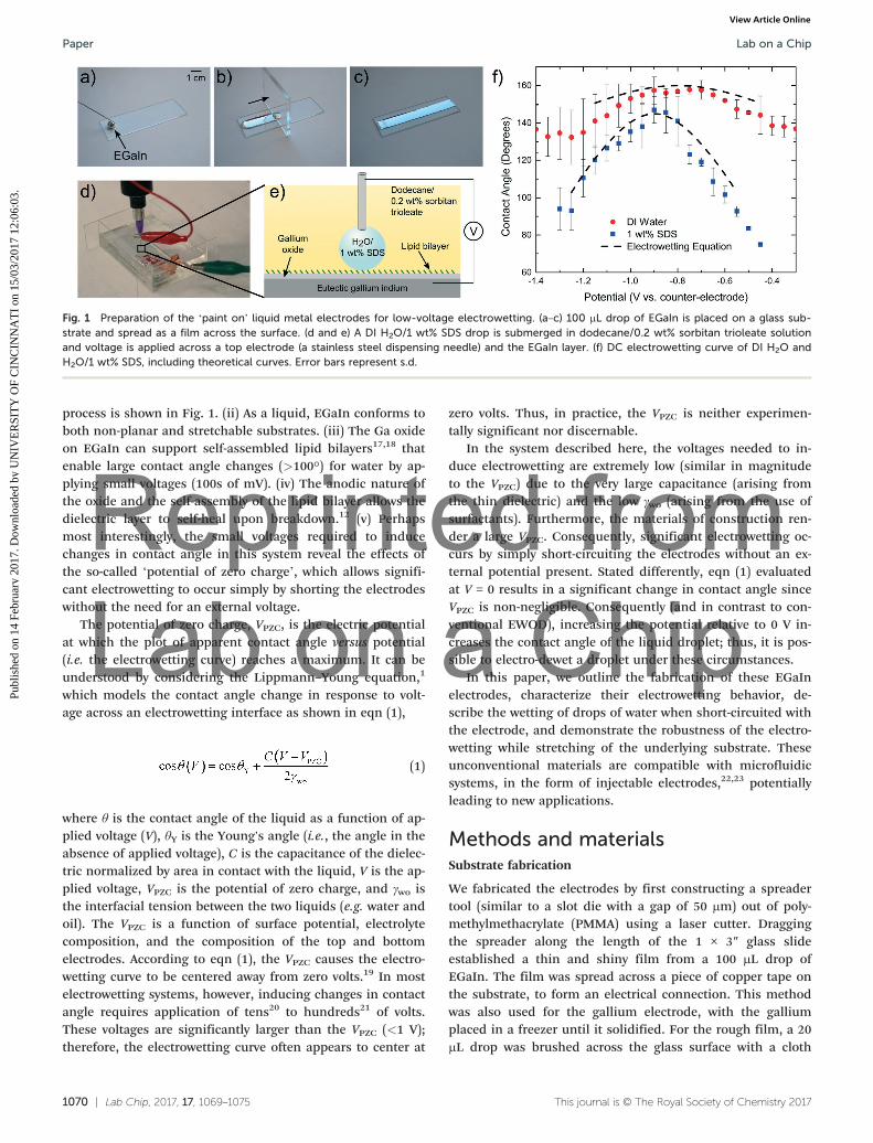
Until now, all the reported experiments were performedon smooth liquid metal surfaces for consistency and simplic-ity of analysis (note that these thicker liquid electrodes aresmooth irrespective of the smoothness of the substrate).However, EWOD on gallium-based alloys does not require apristine surface with a smooth liquid interface. Applicationsmay instead call for thin films of the liquid metal or solidsurfaces. Fig. 3a and b show a thin film of liquid EGaIn anda film of solidified gallium, respectively. The EGaIn was pre-pared by brushing a 20 μL drop across the surface of a glassslide. The gallium was prepared in the same manner as dem-onstrated in Fig. 1 and then solidified in a freezer (m.p.∼30 °C). In spite of the surface heterogeneity present on theEGaIn film, the difference in contact angle change from thepristine EGaIn surface was negligible (albeit with more vari-ance). Similar results were seen with solidified gallium, indi-cating that the electrowetting is dependent on the surfaceproperties of the gallium oxide, rather than the phase of theunderlying electrode.
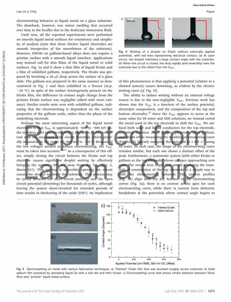
Perhaps the most interesting aspect of the liquid metalelectrodes is that VPZC is approximately −800 to −900 mV (vs.the stainless steel counter-electrode); this value is also consis-tent with the measured open circuit potential, which gener-ally measured in the range of −800 mV to −1.0 V. Because ofthe low voltages needed to induce electrowetting, the VPZCmust be taken into account.19,32 As a consequence of this off-set, simply closing the circuit between the EGaIn and topelectrode causes significant droplet wetting by effectivelybringing the system ∼800 mV away from the VPZC (Fig. 4,Movie S2†). This wetting is reversible; opening the circuitcauses the droplet to dewet the substrate. This process maybe cycled between the short circuit (wetting) and the opencircuit potential (dewetting) for thousands of cycles, althoughleaving the system short-circuited for extended periods oftime results in thickening of the oxide (ESI†). An implication
of this phenomenon is that applying a potential (relative to ashorted system) causes dewetting, as evident by the electro-wetting curve (cf. Fig. 1f).
The ability to induce wetting without an external voltagesource is due to the non-negligible VPZC. Previous work hasshown that the VPZC is a function of the surface potential,electrolyte composition, and the composition of the top andbottom electrodes.32 Since the VPZC appears to occur at thesame value for DI water and SDS solutions, we instead variedthe metal used in the top electrode to shift the VPZC. We uti-lized both solid and liquid conductors for the top electrode,including stainless steel, copper, platinum, solid gallium,and EGaIn while measuring the resulting electrowetting curve(Fig. 5a) by linearly sweeping the potential at 1 mV s−1 usingDI water. In each case, the shape of the electrowetting curveremains similar, but each one shows a distinct offset of thepeak. Furthermore, a symmetric system (with either EGaIn orgallium as the top electrode) shows an apex approaching zerovolts. The results here imply that simply changing the mate-rials of construction of the top electrode is a simple way toshift the electrowetting behavior. The current profiles(Fig. 5b) align with the key features in the electrowettingcurves (Fig. 5a); there is no current at the apex for eachelectrowetting curve, while there is current from dielectricbreakdown at the potentials where contact angle begins to
Fig. 3 Electrowetting on metal with various fabrication techniques. a) “Painted” EGaIn film that was brushed roughly across substrate. b) Solidgallium film prepared by spreading liquid Ga with a slot-die and then frozen. c) Electrowetting curve that shows similar behavior between thesefilms and “pristine” liquid metal surface.
Fig. 4 Wetting of a droplet on EGaIn without externally appliedpotentials, with red lines representing electrical contact. (a) At opencircuit, the droplet maintains a large contact angle with the substrate.(b) When the circuit is closed, the drop rapidly (and reversibly) wets thesubstrate due to the offset from the VPZC.
Lab on a Chip Paper
Publ
ishe
d on
14
Febr
uary
201
7. D
ownl
oade
d by
UN
IVE
RSI
TY
OF
CIN
CIN
NA
TI
on 1
5/03
/201
7 12
:06:
03.
View Article Online

Reprinted from Lab on a Chip
1074 | Lab Chip, 2017, 17, 1069–1075 This journal is © The Royal Society of Chemistry 2017
saturate. Replicating the electrowetting curve with a Ag/AgClreference electrode inserted into the solution causes the apexof the respective curves to center near a single value (approxi-mately −0.6 V vs. Ag/AgCl) (Fig. 5c). This collapse occurs be-cause the Ag/AgCl reference electrode replaces the role of thetop electrode in defining the VPZC. Moreover, the current pro-files in Fig. 5d indicate that current only occurs away fromthe apex of the curves.
Conclusions
This paper demonstrates a robust system for electrowetting-on-dielectric that is simple to fabricate, self-healing, stretch-able, and operates at low voltages to achieve reversible wet-ting and dewetting. This system is also capable of inducingwetting without an external potential due to the low interfa-cial tension of the droplet and the non-negligible ‘potentialof zero charge’ arising from the materials of construction.Applying a potential relative to this shorted configuration re-sults in dewetting, reaching a maximum contact angle at thepotential of zero charge. The combined simplicity of this sys-tem and its ability to electrowet without externally applied
voltage provides a simple strategy to manipulate liquid drop-lets. These unconventional electrodes may also enable or fa-cilitate electrowetting in new settings, such as within micro-fluidics (e.g. injectable electrodes), across rough surfaces,and on stretchable substrates.
Author contributions
All authors contributed to experimental design. CBE, IDJ, andLRM carried out experiments. CBE and IDJ carried out dataanalysis. CBE, IDJ, JH, and MDD wrote the manuscript. MDDand JH supervised the research. The authors declare no com-peting financial interests.
Acknowledgements
MDD gratefully acknowledges support from AFRL, NSF(CMMI-0954321), and U.S. Army Research Office (ARO) (Con-tract No. W911NF-13-C-0045). The authors appreciate helpfulconversations with Frieder Mugele, Jakub Kedzierski, EdBowden, and Karen Daniels.
Fig. 5 The point of zero charge varies with materials of construction. (a) Electrowetting curve of DI water with platinum, stainless steel, copper,gallium, and EGaIn top electrodes. EGaIn film serves as the substrate electrode for electrowetting. (b) Linear sweep voltammogram of two-electrode system at 1 mV s−1. (c) Electrowetting curve of DI water with varied top electrodes and Ag/AgCl reference electrode. (d) Linear sweepvoltammogram of three-electrode system at 1 mV s−1.
Lab on a ChipPaper
Publ
ishe
d on
14
Febr
uary
201
7. D
ownl
oade
d by
UN
IVE
RSI
TY
OF
CIN
CIN
NA
TI
on 1
5/03
/201
7 12
:06:
03.
View Article Online
Reprinted from Lab on a Chip
Lab Chip, 2017, 17, 1069–1075 | 1075This journal is © The Royal Society of Chemistry 2017
References
1 F. Mugele and J. C. Baret, Electrowetting: From basics toapplications, J. Phys.: Condens. Matter, 2005, 17, R705–R774.
2 R. Shamai, D. Andelman, B. Berge and R. Hayes, Water,electricity, and between… On electrowetting and itsapplications, Soft Matter, 2007, 4, 38–45.
3 S. Kuiper and B. H. W. Hendriks, Variable-focus liquid lensfor miniature cameras, Appl. Phys. Lett., 2004, 85, 1128–1130.
4 R. A. Hayes and B. J. Feenstra, Video-speed electronic paperbased on electrowetting, Nature, 2003, 425, 383–385.
5 B. Sun, K. Zhou, Y. Lao, J. Heikenfeld and W. Cheng,Scalable fabrication of electrowetting displays with self-assembled oil dosing, Appl. Phys. Lett., 2007, 91, 11106.
6 S. K. Cho, H. J. Moon and C. J. Kim, Creating, transporting,cutting, and merging liquid droplets by electrowetting-basedactuation for digital microfluidic circuits,J. Microelectromech. Syst., 2003, 12, 70–80.
7 Y.-H. Chang, G.-B. Lee, F.-C. Huang, Y.-Y. Chen and J.-L. Lin,Integrated polymerase chain reaction chips utilizing digitalmicrofluidics, Biomed. Microdevices, 2006, 8, 215–225.
8 D. C. Grahame, The Electrical Double Layer and the Theoryof Electrocapillarity, Chem. Rev., 1947, 41, 441–501.
9 S. Arscott, Electrowetting at a liquid metal-oxide-semiconductor junction, Appl. Phys. Lett., 2013, 103, 144101.
10 H. Moon, S. K. Cho, R. L. Garrell and C.-J. Kim, Low voltageelectrowetting-on-dielectric, J. Appl. Phys., 2002, 92, 4080.
11 A. Schultz, S. Chevalliot, S. Kuiper and J. Heikenfeld,Detailed analysis of defect reduction in electrowettingdielectrics through a two-layer ‘barrier’ approach, Thin SolidFilms, 2013, 534, 348–355.
12 M. Dhindsa, J. Heikenfeld, W. Weekamp and S. Kuiper,Electrowetting without Electrolysis on Self-Healing Dielec-trics, Langmuir, 2011, 27, 5665–5670.
13 A. A. Kornyshev, et al. Ultra-Low-Voltage Electrowetting,J. Phys. Chem. C, 2010, 114, 14885–14890.
14 M. D. Dickey, et al. Eutectic Gallium-Indium (EGaIn): A Liq-uid Metal Alloy for the Formation of Stable Structures inMicrochannels at Room Temperature, Adv. Funct. Mater.,2008, 18, 1097–1104.
15 M. J. Regan, et al. X-ray study of the oxidation of liquid-gallium surfaces, Phys. Rev. B: Condens. Matter, 1997, 55,10786–10790.
16 Y. Lin, et al. Handwritten, Soft Circuit Boards and AntennasUsing Liquid Metal Nanoparticles, Small, 2015, 11, 6397–6403.
17 I. F. Guha, J. Kedzierski and B. Abedian, Low-voltageelectrowetting on a lipid bilayer formed on hafnium oxide,Appl. Phys. Lett., 2011, 99, 24105.
18 J. T. Kedzierski, R. Batra, S. Berry, I. Guha and B. Abedian,Validation of the trapped charge model of electrowettingcontact angle saturation on lipid bilayers, J. Appl. Phys.,2013, 114, 24901.
19 D. J. Lomax, et al. Ultra-low voltage electrowetting usinggraphite surfaces, Soft Matter, 2016, 12, 8798–8804.
20 E. Seyrat and R. A. Hayes, Amorphous fluoropolymers asinsulators for reversible low-voltage electrowetting, J. Appl.Phys., 2001, 90, 1383–1386.
21 H. J. J. Verheijen and M. W. J. Prins, ReversibleElectrowetting and Trapping of Charge: Model andExperiments, Langmuir, 1999, 15, 6616–6620.
22 J.-H. So and M. D. Dickey, Inherently aligned microfluidicelectrodes composed of liquid metal, Lab Chip, 2011, 11,905–911.
23 D. P. Parekh, C. Ladd, L. Panich, K. Moussa and M. D.Dickey, 3D printing of liquid metals as fugitive inks forfabrication of 3D microfluidic channels, Lab Chip, 2016, 16,1812–1820.
24 M. Vallet, M. Vallade and B. Berge, Limiting phenomena forthe spreading of water on polymer films by electrowetting,Eur. Phys. J. B, 1999, 11, 583–591.
25 A. I. Drygiannakis, A. G. Papathanasiou and A. G. Boudouvis,On the Connection between Dielectric Breakdown Strength,Trapping of Charge, and Contact Angle Saturation inElectrowetting, Langmuir, 2009, 25, 147–152.
26 S. Chevalliot, S. Kuiper and J. Heikenfeld, ExperimentalValidation of the Invariance of Electrowetting Contact AngleSaturation, J. Adhes. Sci. Technol., 2012, 26, 1909–1930.
27 F. Mugele, Fundamental challenges in electrowetting: fromequilibrium shapes to contact angle saturation and dropdynamics, Soft Matter, 2009, 5, 3377.
28 A. Quinn, R. Sedev and J. Ralston, Contact AngleSaturation in Electrowetting, J. Phys. Chem. B, 2005, 109,6268–6275.
29 M. Paneru, C. Priest, R. Sedev and J. Ralston, Static andDynamic Electrowetting of an Ionic Liquid in a Solid/Liquid/Liquid System, J. Am. Chem. Soc., 2010, 132,8301–8308.
30 F. Li and F. Mugele, How to make sticky surfaces slippery:Contact angle hysteresis in electrowetting with alternatingvoltage, Appl. Phys. Lett., 2008, 92, 244108.
31 X. Tan, Z. Zhou and M. M.-C. Cheng, Electrowetting ondielectric experiments using graphene, Nanotechnology,2012, 23, 375501.
32 J. Kedzierski and S. Berry, Engineering the ElectrocapillaryBehavior of Electrolyte Droplets on Thin FluoropolymerFilms, Langmuir, 2006, 22, 5690–5696.
Lab on a Chip Paper
Publ
ishe
d on
14
Febr
uary
201
7. D
ownl
oade
d by
UN
IVE
RSI
TY
OF
CIN
CIN
NA
TI
on 1
5/03
/201
7 12
:06:
03.
View Article Online