Embed Size (px)
Citation preview
7/28/2019 Introduction for Solid Edge
http://slidepdf.com/reader/full/introduction-for-solid-edge 1/5
Page1
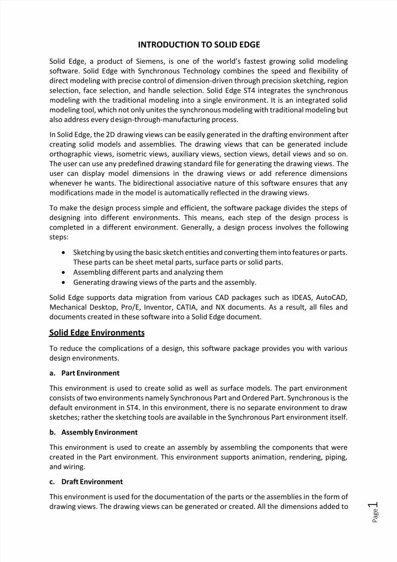
INTRODUCTION TO SOLID EDGE
Solid Edge, a product of Siemens, is one of the world’s fastest growing solid modeling
software. Solid Edge with Synchronous Technology combines the speed and flexibility of
direct modeling with precise control of dimension-driven through precision sketching, region
selection, face selection, and handle selection. Solid Edge ST4 integrates the synchronous
modeling with the traditional modeling into a single environment. It is an integrated solidmodeling tool, which not only unites the synchronous modeling with traditional modeling but
also address every design-through-manufacturing process.
In Solid Edge, the 2D drawing views can be easily generated in the drafting environment after
creating solid models and assemblies. The drawing views that can be generated include
orthographic views, isometric views, auxiliary views, section views, detail views and so on.
The user can use any predefined drawing standard file for generating the drawing views. The
user can display model dimensions in the drawing views or add reference dimensions
whenever he wants. The bidirectional associative nature of this software ensures that any
modifications made in the model is automatically reflected in the drawing views.
To make the design process simple and efficient, the software package divides the steps of
designing into different environments. This means, each step of the design process is
completed in a different environment. Generally, a design process involves the following
steps:
Sketching by using the basic sketch entities and converting them into features or parts.
These parts can be sheet metal parts, surface parts or solid parts.
Assembling different parts and analyzing them
Generating drawing views of the parts and the assembly.
Solid Edge supports data migration from various CAD packages such as IDEAS, AutoCAD,Mechanical Desktop, Pro/E, Inventor, CATIA, and NX documents. As a result, all files and
documents created in these software into a Solid Edge document.
Solid Edge Environments
To reduce the complications of a design, this software package provides you with various
design environments.
a. Part Environment
This environment is used to create solid as well as surface models. The part environment
consists of two environments namely Synchronous Part and Ordered Part. Synchronous is the
default environment in ST4. In this environment, there is no separate environment to draw
sketches; rather the sketching tools are available in the Synchronous Part environment itself.
b. Assembly Environment
This environment is used to create an assembly by assembling the components that were
created in the Part environment. This environment supports animation, rendering, piping,
and wiring.
c. Draft Environment
This environment is used for the documentation of the parts or the assemblies in the form of
drawing views. The drawing views can be generated or created. All the dimensions added to

7/28/2019 Introduction for Solid Edge
http://slidepdf.com/reader/full/introduction-for-solid-edge 2/5
Page2
the component in the part environment during its creation can be displayed in the drawing
views in this environment.
d. Sheet Metal Environment
This environment is used to create sheet metal components.
e. Weldment Environment
This environment enables you to insert components from the part or the assembly
environment and apply weld beads to the parts or the assembly. This environment is
associative with the part and assembly environment.
User Interface of Solid Edge
Prompt Line: If the user invoke a tool, the prompt line is displayed below the command bar.
This line is very useful while creating a model, because it provides the user with the prompt
sequences to use a tool.
PathFinder: The PathFinder is present on the left of the drawing area. It lists all occurences of features and sketches of a model in a chronicle sequences.
Docking Window: The docking window is available on the left of the screen and remains
collapsed by default. It has different tabs on the top. These tabs can be used to activate the
feature library, family of parts etc.
Ribbon: The Ribbon is available at the top of the solid edge window and contains all
application tools. It is a collection of tabs. Each tab has different groups and each group is a
collection of similar tools.
Quick Access toolbar: It is available on the top-left of the title bar of the solid edge window.It proves an access to the frequently used commands such as New, Open, Undo, Redo, Save
and Print.
Application Button: It is available on the top left corner of the solid edge window. It is present
in all environments. On choosing this button, the Application menu containing the options for
creating, opening, saving, and managing documents will be displayed.
Status Bar: It is available at the bottom of the solid edge window. It enables the user to quickly
access all the view controls like Zoom Area, Zoom, Fit, Pan, Rotate, Sketch View, View
Orientation, and View styles.
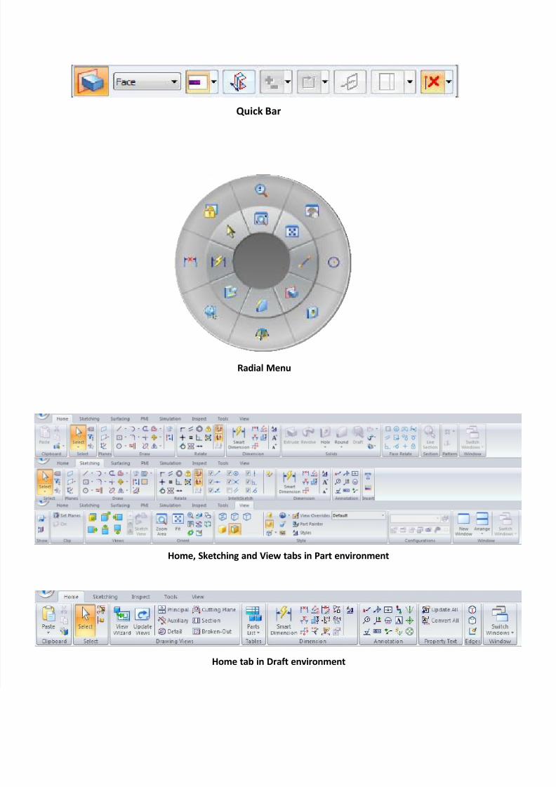
QuickBar: It provides the command options for the active tool.
Radial Menu: Radial menu is a set of tools arranged radially. To invoke a tool from the radial
menu, press the right mouse button and drag the cursor. Keeping the right mouse button
pressed, move the cursor over the tool to be invoked. The user can add or remove tools from
the radial menu.
Part Environment Tabs: There are several tabs in the Ribbon that can be invoked in the part
environment.
i. Home
ii.
Sketchingiii. Surfacing
iv. PMI
v. Simulation
vi.
Inspectvii. Tools
viii. View

7/28/2019 Introduction for Solid Edge
http://slidepdf.com/reader/full/introduction-for-solid-edge 3/5
Page3
Tools used in Solid Edge
DRAW tools:
Line
o Line
o Curve
o Point Rectangle
o Rectangle by Center
o Rectangle by 2 Points
o Rectangle by 3 Points
o Polygon by Center
Circle
o Circle by 3 Points
o Circle by Center Point
o Tangent Circle
o Ellipse by Center pointo Ellipse by 3 Points
Arc
o Tangent Arc
o Arc by 3 Points
o Arc by Center Point Fillet
Chamfer
Extend to Next
Trim
Trim Corner
Offset
Move
Rotate
Split
Mirror
Scale
Stretch
RELATE tools:
Connect
Parallel
Concentric
Horizontal/Vertical
Equal
Tangent
Symmetric
Perpendicular
Lock
DIMENSION tools:
Smart Dimension
Distance Between
Angle Between
Angular Coordinate Dimension
Coordinate Dimension
Symmetric Diameter
SOLIDS tools:
Extrude
Revolve
Hole
o Hole
o Thread
Round
o Round
o Blend
o Chamfer Equal Setbacks
o Chamfer Unequal Setbacks
o Draft
Thin Wall
o Rib
o Web Network
o Lip
o Vent
Add
o Sweep
o Loft
o Helix
o Normal
o Thicken
Cut
o Sweep
o Loft
o Helix
o Normal

7/28/2019 Introduction for Solid Edge
http://slidepdf.com/reader/full/introduction-for-solid-edge 4/5
Application Button
Quick Access toolbar Groups Ribbon
Base Coordinate System
PathFinder
View Orientation Triad
Status bar
Docking Window
Solid Edge ST4 Part environment
7/28/2019 Introduction for Solid Edge
http://slidepdf.com/reader/full/introduction-for-solid-edge 5/5
Quick Bar
Radial Menu
Home, Sketching and View tabs in Part environment
Home tab in Draft environment