Embed Size (px)
Citation preview

Introduction for Development, Application and Performance of
Double Circular Arc Gear
Double Circular Arc (DCA) gear is researched since 1965 in China. After many years
investigation, research and test in the gear research rooms in several university and
gear research institutions, the Tooth Form Standard for DCA gear was determined in
1981 and the DCA gear are used widely in Chinese metallurgy and mine machinery,
textile machinery and oil producing equipment since then. China is a large oil
production country and currently it has more than tens thousands of pumping units
under use in various oilfields in China. All of the gear reducers used on these
pumping units are DCA gear reducers and involute gear had been eliminated by the
end of the 1970s. The reason of elimination of involute gear is that overall pittings
appeared on this kind of involute gear which were used on the pumping units. The
main advantages of DCA gear are the higher contact strength than involute gear’s
and stronger in pitting-resistance. The bending strength of DCA gear is a slight higher
than involute gear’s. So the DCA gear are commonly welcomed by many customers
in the world.
Up till now, LS Brand pumping unit with DCA gear reducers have been exported to
more than ten countries, such as: USA, Canada, Argentina, Venezuela, Brazil,
Ecuador, Egypt, Oman, India, Indonesia, Azerbaijan, Congo and Gabon, etc.

Introduction for Double Circular Arc Gear Design and Calculation
1. Type, feature and application for circular arc gear drive
Circular arc gear drive is a new kind of gear drive developed in recent tens years.
Since 1958, Our country has had large quantity of research, test and popularization
in factories, universities and scientific research institutions. And currently it has been
used widely in metallurgy, mine, lifting & transportation machinery as well as high
speed gear drive.
Fig. 1 is the outside review for circular arc gear drive. It’s a kind of helical (or
herringbone) gear taking circular arc as the tooth form. In order to convenient
machining, we usually make the normal plane tooth form as circular arc and
transverse profile as approximate circular arc. According to the tooth form of circular
arc gear, the circular arc gear is divided into single circular arc gear drive and double
circular arc (DCA) gear drive. We introduce mainly DCA gear drive herewith. As show
in Fig.2 for the DCA gear drive, the large and small gears adopt same tooth profile,
the tooth profile at part of addendum is convex circular arc and the tooth profile at the
part of addendum is concave circular arc, the whole tooth profile consists of convex
and concave circular arcs.
Fig. 1 Fig.2 DCA gear drive
Page 2 of 30

1.1 DCA gear drive
Fig. 3 Sketch of engagement of DCA gear drive
As show in Fig. 3, the large and small gears of DCA gear drive adopt same tooth
form and their tooth forms consist of two sections of circular arcs, its addendum part
is convex circular arc and dedendum part is concave circular arc. So, the DCA gear
drive is equalent to the two pairs of single circular arc gears to be compounded to
work. In the course of drive, one pair is driven by convex tooth to concave tooth and
instantaneous contact point KT; and the other pair is driven by concave tooth to
convex tooth and instantaneous contact point KA. So, during drive, at front and rear
of pitch point, there are two contacting lines at same time and the instantaneous
contact points KT and KA which will move axially along with their self contacting lines.
These two instantaneous contact points KT and KA are located in two different end
sections, the axial-distance qTA is called axial distance of both simultaneous contact
points on same tooth. It’s because one pair of tooth surface has two points to be
contacted simultaneously at two contacting lines, this kind of drive is called double
contacting lines drive.
Page 3 of 30

Fig. 4 Basic tooth form of step type DCA gear
Fig.4 is the basic tooth form of step type DCA gear, the thickness of its addendum
part (convex tooth) is reduced, and the thickness of dedendum part (concave tooth)
increased. So the un-working tooth surface between convex and concave tooth forms
formed a step, the transition curve in this area is a little arc. At the time of engagent,
this kind of gear, in the un-working tooth surfaces, will form a larger space to avoide
the defects on un-working tooth surfaces contact. In addition, because of increase of
thickness at dedendum so that the bending strength at dedendum is increased
comparing with common tangent type circular arc gear and also if the ratio of pitch
thickness S2/S1 is selected properly, the bending strengthes in the waist of tooth and
dedendum are approximate equal. Thus obtain max. bearing capability. The bearing
capability of step type DCA gear is about 40~60% higher than single circular arc
gear. Since step type DCA gear drive has a serial advantages and received widely
attention in the line of gear in different countries, currently it’s under gradually
popularization and application.
DCA gear drive has the following features:
1) High bending strength. Under the condition of same geometric parametas, the
simultaneous working contact points increase one time and accordingly, the load
shared on each contact point will be half in the theory, so the strength of DCA
gear is higher. The bending strength shall be 30% higher than involute gear if its
tooth form design is appropriate.
Page 4 of 30

2) High contact strength. In addition to more contact points, the total length of two
transient contact lines formed after running is longer than single circular arc
gear’s and generally its pressure angle is selected smaller than single circular are
gear’s, so the contact strength of DCA gear is obviously higher than SCA gear’s.
3) Both gears of DCA gear drive adopt convex teeth for addendum and concave
teeth for dedendum: convex-concave teeth form, so it could use one hobbing
cutter for one pair of gear cutting.
4) More stable drive, less vibration and noise.
2. Engagement feature of circular arc gear drive
The engagement feature of DCA gear drive is important quality index to check the
stability of gear drive. In order to guarantee the gear drive stably and continuously,
it’s not only to request the teeth surfaces of one pair gear to realize fixed drive ratio to
drive but also request each pair of teeth “contact” stably, this need the coincidence
degree to guarantee. Reasonable selection of coincidence degree is not only to
guarantee the drive stability but also to increase the bearing capability of drive,
especially in DCA gear drive.
2.2 Engagement feature of DCA gear drive
2.2.1 Axial-distance qTA between two simultaneously contact points on the
same working teeth surfaces.
According to law that the common tangent of both teeth surfaces at contact points
must be crossed with pitch line, we may calculate approximately the axial-distance
qTA between both the simultaneous contacted points kT and kA on the working teeth
surfaces, as per to Fig.5:
0.5πmn+2lα-0.5jnqTA=——————————— - 2ρα cosαn sinβ (1)
sinβ
In which: jn is normal side tolerance.
Ratio of qTA and axial tooth distance Px is double points distance coefficient λ.
qTAλ=————— (2)
Px
The λ is defined not only by tooth form parameters, it will be changed as per the
change of spiral angle β.Page 5 of 30

Fig. 5 Engagement characteristic for DCA gear (pitch circle developed view)
2.2.2 Multi points engagement coefficient
During the course of gear drive, the number of simultaneous contat point of teeth will
be changed periodically. If the working width of gear b=mpx+△b (m is integer, △b is
mantissa) in the scope of turning one tooth, it may have 2m points, 2m+1 points and
2m+2 points contact, when the relevant contacting points working, the ratio of turned
pitch circle arc length and circular pitch is called multi-point engagement coefficient Page 6 of 30
Path of Contact Path of Contact
Segment line

and to be separalely as ε2md, ε(2m+1)d, ε(2m+2)d. we will treat them as 3 kinds of situation
according to the large or small of △b and qTA, to calculate as per Table. 1.
For example: at the situation of showing in Fig. 5, △b<(Px-qTA), so,
2△b △bε2d=1- ———, ε3d = 2 ———. Px Px
Table 1 Calculation equation for multi-point engagement coefficientName of
engagement coefficient
Code Situation I Situation II Situation IIIName of engagement coefficient
Code
When △b≤Px-qTA
When (Px-qTA)≤△b≤qTA When △b≥qTA
2m points engagement coefficient
ε2md
2△b1- ————
Px
qTA-△b ————
Px
___
(2m+1) points engagement coefficient
ε(2m+1)d
2△b——————
Px
2(Px - qTA) ——————
Px
2△b2 - ————
Px
(2m+2) points engagement coefficient
ε(2m+2)d___
△b -(Px - qTA) ——————
Px
2△b———— -1
Px
2.2.3 Multi-pair of teeth engagement coefficient
During drive, the working teeth pair number at same time will be changed periodically
also. In the scope of turning on tooth, may be, it has m pair of teeth, (m+1) pairs of
teeth and (m+2) pair of teeth to join the work. When the relevant teeth working in
pairs, the ratio of turned pitch arc length and circular pitch is called multi-pair teeth
engagement coefficient. To be as εmz,ε(m+1)z and ε(m+2)z, we may treat them as 2 kinds
of situations according to △b’s large or small and calculate per Table 2.
qTA+△bAccording to the situations showed in Fig. 5, △b≤Px-qTA, so, ε1x=1- ———— ,
Px qTA+△b
ε2x=—————. In which, the min. working teeth is one pair, so, when we calculate thePx
strength, we should conside the condition of one pair of teeth and two points
engagement.
Page 7 of 30

Table 2 Calculation equation for multi-pair of teeth engagement coefficient
Name of engagement
coefficient
Code Situation I Situation IIName of engagement
coefficient
Code
When △b≤(Px-qTA) When △b≥(Px-qTA)
Engagement coefficient for
m pair of teeth
εmz qTA+△b1- —————
Px___
Engagement coefficient for
(m+1) pair of teeth
ε(m+1)z qTA+△b——————
Px
qTA+△b2 - ——————
Px
Engagement coefficient for
(m+2) pair of teeth
ε(m+2)z____
qTA+△b——————— - 1
Px
2.2.4 Determination of tooth width b
In the drive of double circular arc gear, it exists multi-pair of teeth engagement and
multi-point engagement and the situation is complicated. So, if it requires different
engaged teeth pairs and different contact point numbers, its min. tooth width bmin, is
not same also. The min. tooth width bmin of DCA gear to be calculated per Table 3.
Table 3 Calculation Table of min. tooth width
Design requirements Calculation equations
At least m pair of teeth and 2m of contact
points work at same time.
At least m pair of teeth and 2m-1 of
contact points work at same time.
At least m pair of teeth and 2m-2 of
contact points work at same time.
bmin=mPx
bmin=(m+λ-1)Px
bmin=(m-λ) Px
For example: at least 2 pairs of teeth and two points contact, the min. tooth width
bmin=(m-λ)Px =(2-λ)Px
at least 2 pairs of teeth and 3 points contact, the min. tooth width
bmin=(m+λ-1)Px =(1+λ)Px
The tooth width b to be determined as per following equation:
b= bmin+ △b1 (3)
Page 8 of 30

Selection of min. tooth width is recommended as per following
equation:
bmin=(m-λ) Px
△b to be selected as per following equation:
△b=(0.15~0.35) Px
3. DCA gear’s basic tooth form and module series.
DCA gear’s basic tooth form means basic rack’s normal plane tooth form. For
example: take tooth of basic rack as slot or the slot of basic rack as tooth, the tooth
form formed from above is hobbing cutter’s normal plane tooth form.
3.2 DCA gear’s basic tooth form
In 1981, our country formulated the basic tooth form standard for DCA gear
(JB2940-81), this standard is applicable to the DCA gear drive under the condition of
tooth surface hardness not exceed to 350 HB and the tooth surface exceed to 350
HB without tooth surface grinding, normal plane module mn=2~32mm. Please refer to
Table 4 for basic tooth form and its parameters.
Fig. 6
Code: a0—pressure angle; h—whole depth; ha—addendum; hf—inside pitch line
length; ρa—circular arc radius of convex tooth flank profile; ρf—circular arc radius of
concave tooth flank profile; xa — travel motion of convex flank profile center;
Page 9 of 30

_xf — travel motion of concave flank profile center; sa—chordal thickness at convex
tooth contact point; hk—distance from contact point to pitch line; la—offset value of
convex flank profile center; lf—offset value of concave flank profile center; hja—
distance from the tangent point connecting circular arc and concave tooth arc to pitch
line; hjf — distance from intersection point connecting arc and concave tooth arc to _ _pitch line; ef—tooth slot width at concave tooth contact point; sf—chordal thickness at
concave tooth contact point; δ1—convex tooth processing angle; δ2—concave tooth
processing angle; rj—connecting circular arc radius at tooth waist; rg—circular arc
radius at dedendum; j—side tolerance.
Table 4 Basic tooth form and its parametersNormal module mn mm
Parameters of basic tooth formParameters of basic tooth formParameters of basic tooth formParameters of basic tooth formParameters of basic tooth formParameters of basic tooth formParameters of basic tooth formParameters of basic tooth formParameters of basic tooth formParameters of basic tooth formParameters of basic tooth formNormal module mn mm a0 h* h *a h *f ρ *a ρ *f x *a x *f _
s *ah *K l *a
2~3 24° 2 0.9 1.1 1.3 1.42 0.0163 0.0325 1.1173 0.5450 0.6289>3~6 24° 2 0.9 1.1 1.3 1.41 0.0163 0.0285 1.1173 0.5450 0.6289
>6~10 24° 2 0.9 1.1 1.3 1.395 0.0163 0.0224 1.1173 0.5450 0.6289>10~16 24° 2 0.9 1.1 1.3 1.38 0.0163 0.0163 1.1173 0.5450 0.6289>16~32 24° 2 0.9 1.1 1.3 1.36 0.0163 0.0081 1.1173 0.5450 0.6289
Normal module mn mm
Parameters of basic tooth shapeParameters of basic tooth shapeParameters of basic tooth shapeParameters of basic tooth shapeParameters of basic tooth shapeParameters of basic tooth shapeParameters of basic tooth shapeParameters of basic tooth shapeParameters of basic tooth shapeParameters of basic tooth shapeNormal module mn mm l *f h* ja h* jf e *f _
s *fδ1 δ2 r *j r *g j*
2~3 0.7086 0.16 0.20 1.1773 1.9643 6°20’52” 9°6’7” 0.5103 0.4030 0.06>3~6 0.6994 0.16 0.20 1.1773 1.9643 6°20’52” 9°19’30” 0.5078 0.4004 0.06
>6~10 0.6957 0.16 0.20 1.1573 1.9843 6°20’52” 9°10’21” 0.4906 0.3710 0.04>10~16 0.6820 0.16 0.20 1.1573 1.9843 6°20’52” 9°9’49” 0.4885 0.3663 0.04>16~32 0.6638 0.16 0.20 1.1573 1.9843 6°20’52” 9°48’11” 0.4858 0.3598 0.04
Note: The size parameters with * in the table indicate the ratio of this size and
normal module mn, and times normal module mn with these ratios to obtain
this size’s value, for example: h*·mn=h, ρ *a·mn=ρa, ……etc.
3.3 Module series of circular arc gear
Please refer to Table 5 for the normal module series of circular arc gear.
Table 5 Module mn series for circular arc gear (GB1840-89)mm
Page 10 of 30
First series 1.5 2 2.5 3 4 5 6 8 10 12 16 20 25 32 40 50
Second series 2.25 2.75 3.5 4.5 5.5 7 9 14 18 22 28 36 45
4. Geometrical size calculation for DCA gear drive
Table 6 Geometrical size calculation for DCA gear drive
Name CodeCalculation equationCalculation equation
Name Code Small gear Big gear
Center distance a
1 mn(z1+z2)a= —— mt(z1+z2) = —————
2 2cosβ
a should meet strength requirement, the a of gear reducer shall select standard value.
1 mn(z1+z2)a= —— mt(z1+z2) = —————
2 2cosβ
a should meet strength requirement, the a of gear reducer shall select standard value.
Normal module mnDetermined as per the tooth strength calculation or selected as per section 5.1 of this chapter, should select standard value.Determined as per the tooth strength calculation or selected as per section 5.1 of this chapter, should select standard value.
Transverse module mt
mnmt = ————
cosβ
mnmt = ————
cosβ
Tooth number ZzΣ
z1=————1+u
z2=uz1
Spiral angle βmn mn(z1+z2)
cosβ=———— = ——————mt 2a
mn mn(z1+z2)cosβ=———— = ——————
mt 2aDiameter of reference circle
dmnz1
d1=—————cosβ
mnz2d2=——————
cosβDiameter of addendum circle
da da1=d1+2ha da2=d2+2ha
Diameter of dedendum circle
df df1=d1-2hf df2=d2-2hf
Axial tooth spacing Px
πmnPx=—————
sinβ
πmnPx=—————
sinβTooth width (half tooth width i f herr ingbone gear)
b b=bmin+△b bmin please see Table 23.3-3b=bmin+△b bmin please see Table 23.3-3
Calculation for measuring sizeCalculation for measuring sizeCalculation for measuring sizeCalculation for measuring size
Nominal chordal depth_h
_h1=mn[h*-r* a1(1-cosθ)]
_h2=mn[h*-r* a2(1-cosθ)]
Actual chordal depth_hp
_ _ 1hp1=h1+ ——(d’ a1-da1))
2
_ _ 1hp2=h2+ ——(d’ a2-da2))
2
Note: The calculation equations for measuring teeth number of common normal
line K, length of common normal line wk, inclined diameter of dedendum
circle Li and wave length of spiral line wave amplitude, please refer to Table
23.3-7.
Page 11 of 30

5. Selection of basic parameters of circular arc gear drive
The basic parameters of circular arc gear drive: mn, z, β, εβ, φd and φa etc. have great
affection to the bearing capability of drive and working quality, they have close
relationship and mutual restrict between each parameter. The basic relationship
between them should pay attention when selection:
d1=z1mn/cosβ (4)
εβ=b/px=bsinβ/πmn (5)
φd=b/d1=πεβ/z1tanβ=0.5φa(1+µ) (6)
φa=b/a=2φd/(1+µ)=2πεβ/(z1+z2)tanβ (7)
While design, the comprehensive consideration shall be given as per the concrete
conditions.
5.1 Tooth number Z and module mn
when the center distance and tooth width of gear have been defined, take more teeth
and reduce module accordingly, this is not only to increase coincidence degree and
enhance the drive stability, but also to reduce relative sliding speed to improve drive
efficiency and prevent from gluing. But if the module is too small, the bending
strength of tooth will be not enough. So, under the condition of meeting bending
strength of tooth, it should be appropriate to select smaller module.
Generally, to select mn=(0.01~0.02) a (a is center distance). For the large center
distance, stable load and continuous working drive, select smaller value; and for the
small center distance, unstable load and intermittent work drive, select larger value.
In the general gear reducer, it’s used to select mn=(0.0133~0.016) a. If it’s special, for
example the herring bone gear seat of rolling machine with outstanding peak load,
may select mn=(0.025~0.04) a. If it’s high speed drive, select smaller normal module
for stable working.
In addition in the design, we may select the teeth number at first then determine the
module. Generally, take z1≥18~30. Surface hardness HB≤350, if load is not heavy,
should select larger value; the surface hardness HB>350, the load is heavy, should
select smaller value; If the speed is high select larger value. No undercut for circular
arc gear, the min. teeth number shall not be restricted by undercut; but if the teeth
Page 12 of 30

number is less, the module is large, it’s not easy to guarantee the value of
coincidence degree.
5.2 Coincidence degree εβ
To select larger coincidence degree may enhance the stability of drive, lower noise
and improve bearing capability. For middle and low speed drive, we used to select
εβ>2; for high speed gear drive, we recommend εβ>3 or larger value. When we adopt
large coincidence degree, the tolerances of tooth spacing, tooth direction, axial
parallelism and shafting deformation value should be restricted strictly, otherwise it
could not guarantee that several contact tracks to bear load evenly and could not
reach drive stably and proper bearing capability.
The coincidence degree consists of integer part µε and mantissa △ε, i.e. εβ=µε+△ε.
The selected value of mantissa △ε of coincidence degree will have great affection to
the bearing load capability and stability. Generally, the scope of value selection for
mantissa △ε is 0.15~0.35.
If △ε selected is too small, at the time of the contact track enter or break away from
tooth surface, it’s easy to cause tooth crest collapsed and not good for stable drive. If
△ε increased, the stress at tooth crest will be reduced, but if △ε will be increased to
above 0.4, the stress will be reduced slowly; if △ε selected is too much the tooth
width increased so that not to increase contact track numbers at each twinkling.
5.3 Spiral angle β
The spiral angle β has more affections to drive quality. The β increased will cause
equivalent curvature radius reduced so that lower the tooth surface contact strength
and bending strength at dedendum, additionally, it will increase axial force and
reduce bearings life. But if β increased, this will make coincidence degree εβ
increased, if we will obtain: εβ=2.15~3.35 or εβ=3.15~3.35, the drive stability, vibration
and noise will be improved and contact strength and bending strength will be
improved also. So to select β reasonably according to specific situation. General
recommendation for helical gear,β=10°~20°;for herringbone gear,β=25°~35°.
Page 13 of 30

5.4 Tooth width coefficient φd,φa
Fig. 7 Relationship between φd and z1, β, εβ
b bTooth width coefficient φd=——, φa= —— d1 a
Conversion relationship of φd and φa please refer to equations (6) and (7). When z1,
β and εβ defined, check φd or φa according to equations (6) and (7). It’s also to
determine tooth width coefficient first and then to adjust z1, β and εβ’s values with
these equations.
When the values of εβ are 1.25, 2.25, 3.25, use Fig.7 to select a group of suitable
values of φd, z1 and β.
6. Strength calculation of DCA gear
6.1 Strength calculation equation of DCA gear drive.
Page 14 of 30

Please refer to Table 7 for the equation of bending strength of dedendum and
strength of tooth surface contact for DCA gear drive.
Table 7 calculation equations of strength for DCA gear drive
Item Calculation of bending fatigue strength of dedendum
Calculation of fatigue strength of tooth surface contact
Calcu la ted s t r e s s N /mm2
T1KAKVK1 0.86 YEYµYβYFσF =(——————) —————— Yend 2µε+k△ε z1mn2.58
T1KAKVK1KH2 0.73 ZEZµZβZaσH =(—————— ) —————— 2µε+k△ε z1mn2.19
N o r m a l module mm
T1KAKVK1 1/3 YEYµYβYF 1/2.58
mn≥(——————) (—————Yend )
2µε+k△ε z1σFP
T1KAKVK1KH2 1/3 ZEZµZβZa 1/2.19
mn≥(———————) (————— )
2µε+k△ε z1σHP
To r q u e o f small gear N.mm
2µε+k△ε z1σFP 1/0.86
T1=————— m 3n ( —————— )
KAKVK1 YEYµYβYF Yend
2µε+k△ε z1σHP 1/0.73
T1= ————— m3n (——————)
KAKVK1KH2 ZEZµZβZa
A l l o w a n c e stress
N/mm2σFP=σFLimYNYX /SFmin≥σF σHP=σHLimZNZL /SHmin≥σH
S a f e t y coefficient sF=σFLimYNYX /σF≥SFmin SH=σHLimZNZL /σN≥SHmin
Note: For herringbone gear drive, the torque to be calculated according to 0.5T1,
(2µε+k△ε) to be calculated as per half tooth width.
6.2 The signification of each parameter symbol and determination for each coefficient: (1) Small gear tooth number Z1, determined as per Chapter 5.1 of this artiale. (2) The integer parts of superposition degree µε, to reference this chapter 5.2 (3) Using coefficient KA, to see chart 23.2-24. For high-speed gear drive, It should be
recommended as per the experience to choose the 1.02—1.15 times chart value when v=40---70m/s; to choose 1.15---1.3 times chart value for v=70---100m/s, and to choose morethan 1.3 times chart value for v›100m/s.(4)dynamic load factor Kv, to reference to Fig 8.
Page 15 of 30

Fig. 8 Dynamic load factor KV
(5) contact tracks loading assigning coefficient K1, to reference to chart 23.3-13(6) contact tracks loading assigning coefficient KF2, KH2, to reference to Table 8
Table 8 touching-mark loading assigning coefficient for contact tracks.GradeGrade 5 6 7 8KF2KF2 1111KH2 81 Type 1.15 1.23 1.42 1.49
(7) contact tracks coefficient KAε, it is the coefficients considering that since superposition degree mantissa △εincrease make the positive pressure decreasing for each contact tracks. The contact tracks coefficients of DCA gear drive are shown as Fig 9.
Page 16 of 30

Fig 9 The contact tracks coefficient of DCA(8) Elasticity coefficient YE, ZE, To see Table 9(9) gear number ratio coefficient Yu, Zu, to see Fig 10
Fig 10 gear number ratio coefficient Yu, Zu
(10) spiral angle coefficient Yβ, Zβ, to see Fig 11
Page 17 of 30
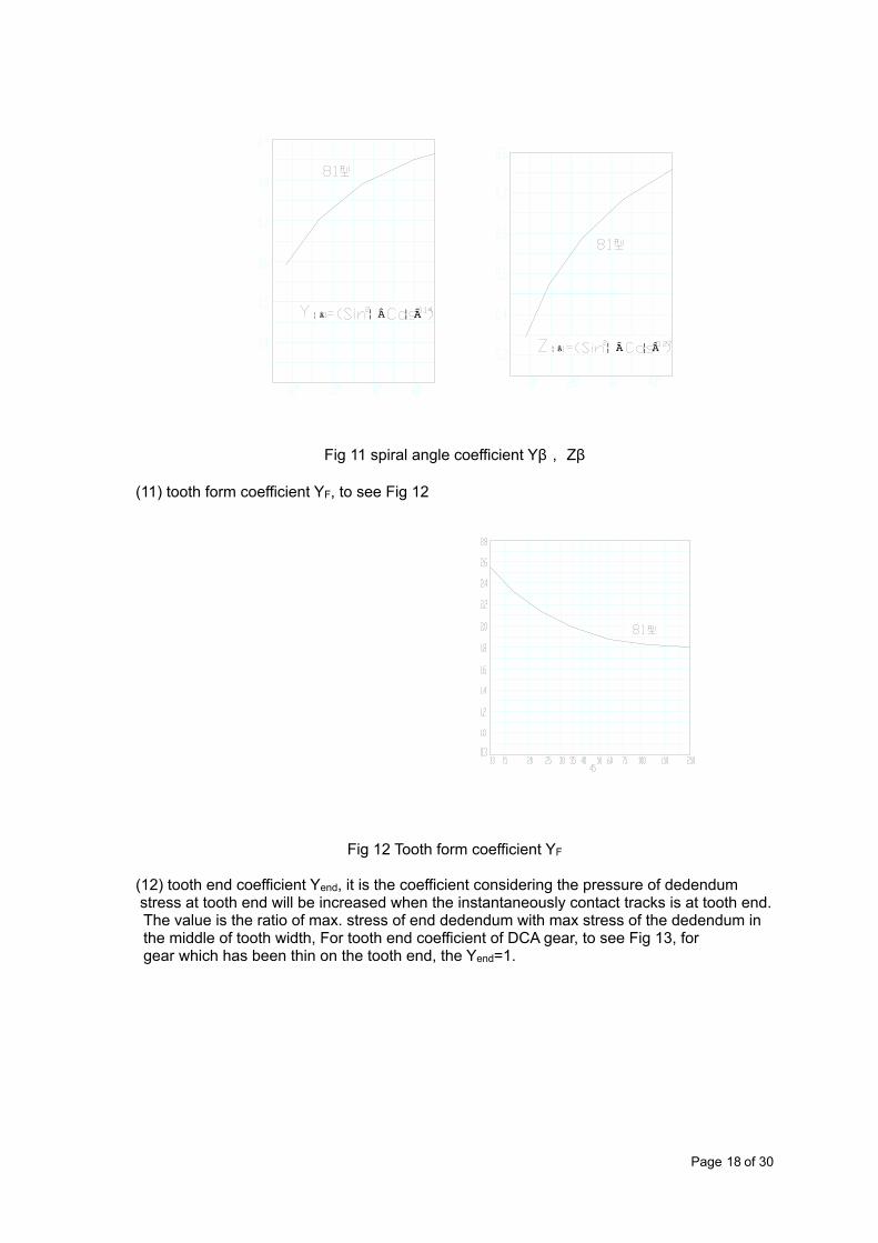
Fig 11 spiral angle coefficient Yβ, Zβ
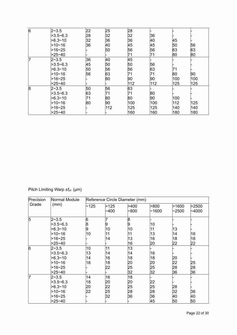
(11) tooth form coefficient YF, to see Fig 12
Fig 12 Tooth form coefficient YF
(12) tooth end coefficient Yend, it is the coefficient considering the pressure of dedendum stress at tooth end will be increased when the instantaneously contact tracks is at tooth end.The value is the ratio of max. stress of end dedendum with max stress of the dedendum in the middle of tooth width, For tooth end coefficient of DCA gear, to see Fig 13, forgear which has been thin on the tooth end, the Yend=1.
Page 18 of 30

Fig 13
(13) contact-arc length coefficient Za, it’s the coefficient considering the affections to contact arc length from module and equivalent teeth number. Please refer to Fig.14. for DAC gear, when the ratio of tooth number u is not 1, the up tooth surface and low tooth surface of a gear, their contact arc lengthes are not same, so the coefficient of contact arc length need
to use the average value of Z a1 and Z a2 , i.e. Z am =0.5 (Z a1 + Z a2 ).
Page 19 of 30

Fig 14 Contact arc length coefficient Za, For DAC gear Zam=0.5(Za1+Za2)
(14) the basic value of bending strength δFE for gear material to see Fig 15. it will be chosen the middle value of scope, the top value will be allowed to used when material is in good quality and better heat-treatment.
Fig 15 Fig 16 Table9 DCA elasticity coefficient YE, ZE,
Tooth form Symbol Unit A couple of forging gear Other MaterialDAC gear YE (N/mm2)0.14 2.073 0.37E/0.14
DAC gear ZE (N/mm2)0.27 31.37 1.123E/0.27
E’=2/E’=2/E’=2/E’=2/E’=2/
For gear working under the symmetry circulation stress, the value of δFIIm will be chosen as
per the chart and it also will be 0.7times of chart value.(15) Contact fatigue limitation stress δHLim of testing tooth surface, to see Fig 16.
Page 20 of 30

Generally, it will be chosen the middle value of the scope. The top value of this chart will be allowed to choose when the material and is in good heat-treatment quality, and with the good structure to meet heat-treatment.(16) life factor YN, ZN,
(17) Size factor YX, to see Fig 17
Fig 17 size factor YX of DAC gear
(18) lubricant factor ZL,
(19) min safety factor SFmin, SHmin, to see table 10
Table10 The reference value of min safety factorSFmin 1.6----1.8SHmin, 1.3----1.5
a- Quenched and tempered steel b- Surface hardened steelc- Casting steeld- All material under the static load
When use of compound lubrication with less friction factor, for the value in Q+T steel gear, times factor 1.4; for the value in carbonized and quenched steel gear, times 1.1.
Ring Gear Radial Tolerance Fr
Precision Grade
Normal Module (mm)
Reference Circle Diameter (mm)Reference Circle Diameter (mm)Reference Circle Diameter (mm)Reference Circle Diameter (mm)Reference Circle Diameter (mm)Reference Circle Diameter (mm)Precision Grade
Normal Module (mm) ~125 >125
~400>400~800
>800~1600
>1600~2500
>2500~4000
5 2~3.5>3.5~6.3>6.3~10>10~16>16~25>25~40
14162022--
1618222532-
182022283645
-2225283645
--28324050
---364050
Page 21 of 30
6 2~3.5>3.5~6.3>6.3~10>10~16>16~25>25~40
22283236--
2532364050-
283236455671
-3640455671
--45506380
---566380
7 2~3.5>3.5~6.3>6.3~10>10~16>16~25>25~40
36455056--
4050566380-
4550567190112
-56637190112
--7180100125
---90100125
8 2~3.5>3.5~6.3>6.3~10>10~16>16~25>25~40
50637180--
56718090112-
637180100125160
-8090100125160
--100112140180
---125140180
Pitch Limiting Warp ±fpt (µm)
Precision Grade
Normal Module (mm)
Reference Circle Diameter (mm)Reference Circle Diameter (mm)Reference Circle Diameter (mm)Reference Circle Diameter (mm)Reference Circle Diameter (mm)Reference Circle Diameter (mm)Precision Grade
Normal Module (mm) ~125 >125
~400>400~800
>800~1600
>1600~2500
>2500~4000
5 2~3.5>3.5~6.3>6.3~10>10~16>16~25>25~40
68910--
79101114-
8910111316
-1011131620
--13141822
---161822
6 2~3.5>3.5~6.3>6.3~10>10~16>16~25>25~40
10131416--
1114161822-
131418202532
-1618202532
--20222836
---252836
7 2~3.5>3.5~6.3>6.3~10>10~16>16~25>25~40
14182022--
1620222532-
1820252836-
-2225283645
--28324050
---364050
Page 22 of 30

8 2~3.5>3.5~6.3>6.3~10>10~16>16~25>25~40
20252832--
2228323645-
252836405063
-3236405063
--40455671
---505671
Axial pitch Internal Tolerance Fβ (µm)Precision Grade
Width of Gear (Axial Pitch) mmWidth of Gear (Axial Pitch) mmWidth of Gear (Axial Pitch) mmWidth of Gear (Axial Pitch) mmWidth of Gear (Axial Pitch) mmWidth of Gear (Axial Pitch) mmPrecision Grade ~40 >40~100 >100~160 >160~250 >250~400 >400~6305 7 10 12 16 18 226 9 12 16 19 24 287 11 16 20 24 28 348 18 25 32 38 45 55
Base Tangent Length Alteration Tolerance FW (µm)Precision Grade
Reference Circle Diameter (mm)Reference Circle Diameter (mm)Reference Circle Diameter (mm)Reference Circle Diameter (mm)Reference Circle Diameter (mm)Reference Circle Diameter (mm)Precision Grade ~125 >125~400 >400~800 >800~1600 >1600~2500 >2500~40005 12 16 20 25 28 406 20 25 32 40 45 637 28 36 45 56 71 908 40 50 63 80 100 125
Axial Parallel ToleranceX axial Parallel Tolerance fx= Fβ Fβ see table above
Y axial Parallel Tolerance fx= Fβ
Fβ see table above
Center Limiting Warp ±fa (µm)Precision Grade
Center Distance (mm)Center Distance (mm)Center Distance (mm)Center Distance (mm)Center Distance (mm)Center Distance (mm)Center Distance (mm)Center Distance (mm)Center Distance (mm)Center Distance (mm)Center Distance (mm)Center Distance (mm)Center Distance (mm)Center Distance (mm)
Page 23 of 30

Precision Grade ~120 >120
~180>180~250
>250~315
>315~400
>400~500
>500~630
>630~800
>800~1000
>1000~1250
>1250~1600
>1600~2000
>2000~2500
>2500~3150
5, 6 17.5 20 23 26 28.5 31.5 35 40 45 52 62 75 87 105
7, 8 27 31.5 36 40.5 44.5 48.5 55 62 70 82 97 115 140 165
Chordal tooth thickness Limiting Warp ±Eh (µm)Precision Grade
N o r m a l M o d u l e (mm)
Reference Circle Diameter (mm)Reference Circle Diameter (mm)Reference Circle Diameter (mm)Reference Circle Diameter (mm)Reference Circle Diameter (mm)Reference Circle Diameter (mm)Reference Circle Diameter (mm)Reference Circle Diameter (mm)Reference Circle Diameter (mm)Reference Circle Diameter (mm)Reference Circle Diameter (mm)Precision Grade
N o r m a l M o d u l e (mm)
≤50 >50~80
>80~120
>120~200
>200~320
>320~500
>500~800
>800~1250
>1250~2000
>2000~3150
>3150~4000
5, 6 2~3.5>3.5~6.3>6.3~10
1620
182125
192327
212530
242732
273034
303437
3741
4145
4550
5060
7, 8 2~3.5>3.5~6.3>6.3~10>10~16>16~32
2025---
222632--
24283442-
2730364565
3034404870
3236425075
-40455575
-45506080
-50556590
--607090
--6575100
Note: for DCA gear, the Chordal tooth thickness Limiting Warp should be ±0.75 Eh
Root Circle Diameter Warp ±Edf (µm)Precision Grade
N o r m a l M o d u l e (mm)
Reference Circle Diameter (mm)Reference Circle Diameter (mm)Reference Circle Diameter (mm)Reference Circle Diameter (mm)Reference Circle Diameter (mm)Reference Circle Diameter (mm)Reference Circle Diameter (mm)Reference Circle Diameter (mm)Reference Circle Diameter (mm)Reference Circle Diameter (mm)Reference Circle Diameter (mm)Precision Grade
N o r m a l M o d u l e (mm)
≤50 >50~80
>80~120
>120~200
>200~320
>320~500
>500~800
>800~1250
>1250~2000
>2000~3150
>3150~4000
5, 6 2~3.5>3.5~6.3>6.3~10
2531-
283445
313748
364252
344856
455263
526067
-6775
--80
--100
---
7, 8 2~3.5>3.5~6.3>6.3~10>10~16>16~32
3040---
344455--
38486075-
44506580120
50557085125
55667590130
-7080100140
-8090110150
--100120160
---140180
---160200
Note: for DCA gear, the tolerance of Root circle diameter should be ±0.75Edf
Tooth Radicel Tolerance Gear Precision Grade ①Gear Precision Grade ①
5 6 7 8
Hole Dim. Torlerance IT5 IT6 IT7IT7Shaft Dim. Torlerance IT5IT5 IT6IT6
Tip Diameter ②Tip Diameter ② IT6 IT7IT7IT7Note: IT – unit of standard tolerance.1 The tolerance is adopted as per the highest precision grade when precision grade of three
groups tolerance are differents.
Page 24 of 30

2 The tolerance is adopted as per IT11 when the tip diameter is not use of benchmark for teeth thickness and teeth depth, but not more than 0.1mn
Tooth Radicel Datum Plane Radial and Transverse Plane Tolerance (µm)Reference Circle Diameter (mm)Reference Circle Diameter (mm) Precision GradePrecision GradeFrom To 5 and 6 7 and 8-- 125 11 18125 400 14 22400 800 20 32800 1600 28 451600 2500 40 632500 4000 63 100
7.7 The formula for Limiting Warp and Tolerance
1) The value of tangent tolerance Fi’, Tangent-teeth tolerance fi’, helix and spirals tolerance ffβ , Radial pitch Limiting Warp ±Fpx , X axial Parallel Tolerance fx , Y axial Parallel Tolerance fy , Center Limiting Warp ±fa can be calculated as following formula:
Fi’ = Fp + fβfi’ = 0.6(fpt + fβ)ffβ = fi’ cosβfpx = fβFpx = Fβfx = Fβfy = 0.5 Fβfa = 0.5(IT6, IT7, IT8)
Here: β --- reference circle helix angle.
2) The value of base tangent length tolerance Ew and teeth thickness tolerance Ea can be calculated as following formula:Ew = -2sinαEh
Ea = -2tanαEhHere: α --- teeth angle.
3) The value of gear pair tangent tolerance Fi ’c equal the sum of tolerance Fi ’ between two gear’s tangent. When the ratio value of two teeth is a integer and not more than 3, Fi ’ can be expressed 25% or more than the calculated value.The value of gear pair tangent – teeth tolerance fi ’c equal the sum of tolerance fi ’c between two gear’s tangent – teeth.
4) The relationship between Limiting warp and tolerance and parameter of gear are listed as below:
Table: The relationship between Limiting warp and tolerance and parameter of the gear
PrecisionGrade
FpFp FrFr FwFw fptfpt fβfβ EhEhEh EdfEdf
Page 25 of 30

PrecisionGrade
A +CA +C Amn+B +CB=0.25AAmn+B +CB=0.25A
B +CB +C Amn+B +CB=0.25AAmn+B +CB=0.25A
A +CA +C Amn+B3 +CAmn+B3 +CAmn+B3 +C Amn+B3Amn+B3
PrecisionGrade
A C A C B C A C A C A B C A B4 1.0 2.5 0.56 7.1 0.34 5.4 0.25 3.15 0.63 3.15 0.96 1.92 2.88 1.92 3.84
5 1.6 4 0.90 11.2 0.54 8.7 0.40 5 0.80 41.2 2.4 3.6 2.4 4.86 2.5 6.3 1.40 18 0.87 14 0.63 8 1 5 1.2 2.4 3.6 2.4 4.8
7 3.55 9 2.24 28 1.22 19.4 0.90 11.2 1.25 6.31.5 3 4.5 3 68 5 12.5 3.15 40 1.7 27 1.25 1.6 2 10 1.5 3 4.5 3 6
Note d- reference circle Dia.; b-face width; L- length of reference circle arc;d- reference circle Dia.; b-face width; L- length of reference circle arc;d- reference circle Dia.; b-face width; L- length of reference circle arc;d- reference circle Dia.; b-face width; L- length of reference circle arc;d- reference circle Dia.; b-face width; L- length of reference circle arc;d- reference circle Dia.; b-face width; L- length of reference circle arc;d- reference circle Dia.; b-face width; L- length of reference circle arc;d- reference circle Dia.; b-face width; L- length of reference circle arc;d- reference circle Dia.; b-face width; L- length of reference circle arc;d- reference circle Dia.; b-face width; L- length of reference circle arc;d- reference circle Dia.; b-face width; L- length of reference circle arc;d- reference circle Dia.; b-face width; L- length of reference circle arc;d- reference circle Dia.; b-face width; L- length of reference circle arc;d- reference circle Dia.; b-face width; L- length of reference circle arc;d- reference circle Dia.; b-face width; L- length of reference circle arc;
Working Chart of DCA Gear (Drive sheave) Parts Normal Module mn 3.5Teeth Number z 29Teeth angle αn 24°Dedendum ha* 0.9Helix angle β 15°44’26” Direction of helix LeftLeftThe type of teeth “81” type“81” typeTeeth Depth h 7Nominal chordal depth h 6.922Precision Grade 8-8-7JB4021-858-8-7JB4021-85Gear pair center and limiting warp α ± fa 220 ± 0.036mating gears Drawing No.mating gears
Teeth Number 92Tolerance Group Inspection item code TolerancePitch tolerance Fp 0.090Pitch Limiting warp fpt ± 0.020Radial pitch limiting warp Fpx ± 0.016
Page 26 of 30
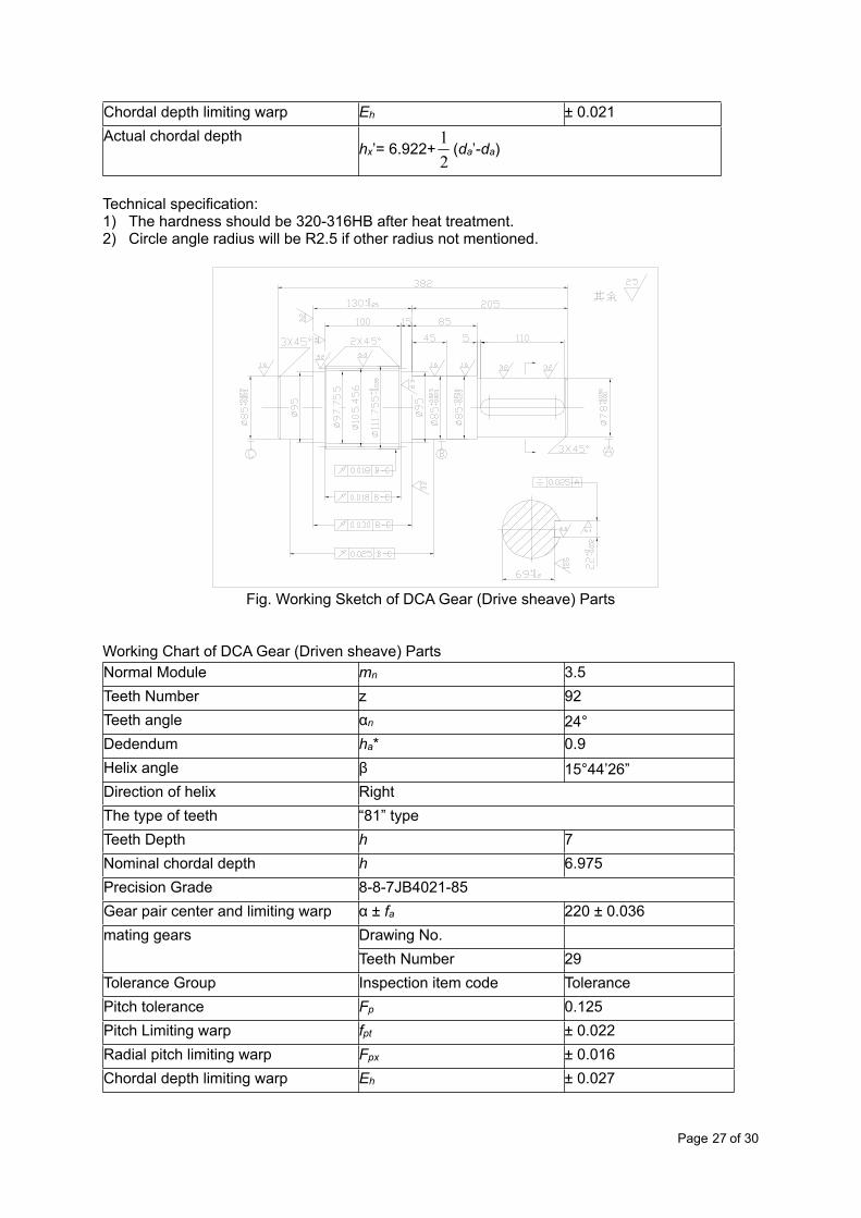
Chordal depth limiting warp Eh ± 0.021Actual chordal depth
hx’= 6.922+ (da’-da)hx’= 6.922+ (da’-da)
Technical specification:1) The hardness should be 320-316HB after heat treatment.2) Circle angle radius will be R2.5 if other radius not mentioned.
Fig. Working Sketch of DCA Gear (Drive sheave) Parts
Working Chart of DCA Gear (Driven sheave) Parts Normal Module mn 3.5Teeth Number z 92Teeth angle αn 24°Dedendum ha* 0.9Helix angle β 15°44’26” Direction of helix RightRightThe type of teeth “81” type“81” typeTeeth Depth h 7Nominal chordal depth h 6.975Precision Grade 8-8-7JB4021-858-8-7JB4021-85Gear pair center and limiting warp α ± fa 220 ± 0.036mating gears Drawing No.mating gears
Teeth Number 29Tolerance Group Inspection item code TolerancePitch tolerance Fp 0.125Pitch Limiting warp fpt ± 0.022Radial pitch limiting warp Fpx ± 0.016Chordal depth limiting warp Eh ± 0.027
Page 27 of 30

Actual chordal depthhx’= 6.975+ (da’-da)hx’= 6.975+ (da’-da)
Technical specification:1) The hardness should be 280-300HB after heat treatment.2) The rough of tooth flank Ra should be 3.2µm.
Fig Working Sketch of DCA Gear (Driven sheave) Parts
Please Note:
All materials above come from Machine Design Handbook, which published by Mechanical Industry Publisher, China, ISBN 7-111-02756-6/TH.282
Page 28 of 30
![From Eye to Insight - Leica Microsystems MZ10 F/Applicatio… · Introduction The roundworm ... Leica S6 routine stereo microscope [8] with the LED2500 light stand, or small illumination](https://img.pdfslide.us/doc/110x75/5f1dae6c23323912da18c2ee/from-eye-to-insight-leica-microsystems-mz10-fapplicatio-introduction-the-roundworm.jpg)


![Devoted t tho Discovere andy Applicatio of Truthn...Devoted t tho Discovere andy Applicatio of Truthn . VOL. 3, No 33.] \ A . J. I> AVIS i CO., I 274 Canal St. NEW YORK, WEEK ENDING](https://img.pdfslide.us/doc/110x75/5e743c318a9d9248d05391ff/devoted-t-tho-discovere-andy-applicatio-of-devoted-t-tho-discovere-andy-applicatio.jpg)