Embed Size (px)
Citation preview

Company/Project Logo
Project NameRequirements DocumentESA Template Ver.2.7, Issue date: 03Jan2018
Prepared by
ReferenceIssue/Revision Date of IssueStatus

Company/Project LogoAPPROVAL
Title: Requirements Document
Issue Number: Revision Number: Author(s): Date: Approved by: Date of Approval:
CHANGE LOGReason for change Issue Revision Date
CHANGE RECORDIssue Number: Revision Number: Reason for change Date Pages Paragraph(s)
DISTRIBUTIONName/Organisational Unit:
Page /

Company/Project LogoTable of contents:
1 INTRODUCTION.................................................................................41.1 Reference Documents...................................................................................51.2 Acronyms......................................................................................................52 USER NEEDS AND USER REQUIREMENTS.......................................52.1 User Needs...................................................................................................52.2 User Requirements.......................................................................................63 SYSTEM REQUIREMENTS.................................................................73.1 System Requirements...................................................................................74 APPENDIX 1.......................................................................................95 APPENDIX 2.....................................................................................116 APPENDIX 3.....................................................................................12
Page /

Company/Project Logo1 INTRODUCTION
In the introduction, the contractor shall describe the requirements engineering approach that intends to follow. In case a waterfall approach to the requirements engineering is retained, the Requirements Document (RD) will be discussed at the BDR. The set of Requirements
The following requirements document template shall be written from the perspective of contractors involved in Business Applications projects.The initial purpose of the Requirements Document (RD) is to make sure that all the user’s needs are listed and agreed. These needs are turned into measurable requirements which can be later tested by the consortium in the System Verification Document.This template structures the minimum requirements of content expected in the Requirements Document deliverable to be reviewed by the ESA during the project execution. Parts with the paragraph title highlighted in green in this template are based on contributions that have been provided in the Full Proposal and that can be reused as starting point and complemented when required.
Concerning the use of this template, please note the following:
Material presented in this plain style is either suggested content for the Requirements Document, or describes the content to be inserted in the corresponding paragraph, as relevant. This is intended to be an example of a response to the related Agency requirements, which the Contractor needs to properly complement. The suggested material may be adopted as is, or modified at the Contractors’ discretion. It remains the responsibility of the Contractor to ensure that all of the Agency’s requirements present in the Management Requirements are properly addressed.
This style is used to identify information that must be modified and/or completed by the Contractor for the proposed activity. This supplementary information should be presented in plain typeface (i.e. not red) in the final version of the Business Plan.
This style is used for explanatory notes and guidance to help you to develop the Requirements Document content (e.g. to indicate a selection between mutually-exclusive options). This information should be removed from the final version of the Requirements Document.
PLEASE, REMOVE THIS TEXT BOX AFTER YOU HAVE STARTED USING

Company/Project Logoherewith described will be the baseline for the following design and development activities
and associated verification. In case an agile method is retained, the contractor shall describe the iteration process and identify the milestones in which the RD shall be discussed with the Agency.
1.1 Reference DocumentsRef. Document ID. Title Rev.[RD1]
1.2 AcronymsTag Description
RD Requirements Document
2 USER NEEDS AND USER REQUIREMENTS
To allow formal traceability of the different requirements, each requirement shall be associated with a unique identifier using a suitable methodology. Such methodology shall use a suitable set of acronyms (e.g. UN for User Needs, UR for User Requirements, SR for System Requirements) to facilitate traceability.
The approach could be different depending on the type of users involved in the project. It could be necessary to identify before User Needs, translate them in measurable Users Requirements and map them into System Requirements; it could also happen Users Needs could be directly mapped into System Requirements or even that a skilled user already has a set of Users Requirements that can be used by the designer for the System Requirements. The approach to be followed is left to the designer; justification shall be anyhow provided.
2.1 User NeedsThe scope of this section is presenting the improvements as desired and expressed by the user and expected to be answered by the proposed system, together with a concise presentation of the high level interaction between the intended system and the different actors involved (e.g. use case). This can be done providing a description of the current situation (before introduction of the service, with the problems to solve) and how this will change after the introduction of the proposed service.
User Needs Description
Any user needs shall be defined on the basis of the following rules. In particular, it will be listed in a row of table as presented in Table 1.
Page /
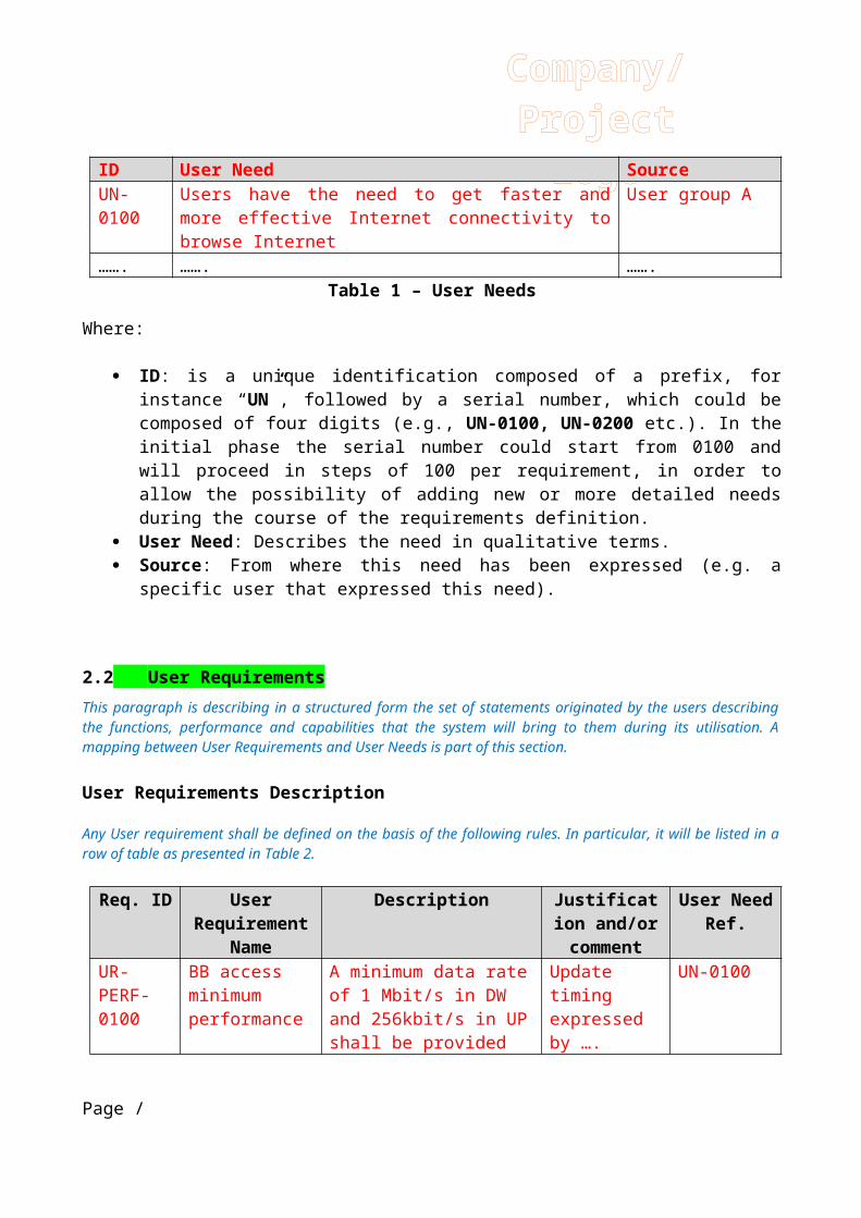
Company/Project LogoID User Need Source
UN-0100
Users have the need to get faster and more effective Internet connectivity to browse Internet
User group A
……. ……. …….Table 1 – User Needs
Where:
ID: is a unique identification composed of a prefix, for instance “UN”, followed by a serial number, which could be composed of four digits (e.g., UN-0100, UN-0200 etc.). In the initial phase the serial number could start from 0100 and will proceed in steps of 100 per requirement, in order to allow the possibility of adding new or more detailed needs during the course of the requirements definition.
User Need: Describes the need in qualitative terms. Source: From where this need has been expressed (e.g. a specific user
that expressed this need).
2.2 User RequirementsThis paragraph is describing in a structured form the set of statements originated by the users describing the functions, performance and capabilities that the system will bring to them during its utilisation. A mapping between User Requirements and User Needs is part of this section.
User Requirements Description
Any User requirement shall be defined on the basis of the following rules. In particular, it will be listed in a row of table as presented in Table 2.
Req. ID User Requiremen
t Name
Description Justification and/or comment
User Need Ref.
UR-PERF-0100
BB access minimum performance
A minimum data rate of 1 Mbit/s in DW and 256kbit/s in UP shall be provided to each user to browse Internet
Update timing expressed by ….
UN-0100
UR-PERF-0200
BB access typical performance
Each user shall also get up to 10 Mbit/s DW and 1 Mbit/s UP with a 1:10 congestion rate on their network
Update timing expressed by ….
UN-0100
……. ……. ……. ……. …….
Page /

Company/Project LogoTable 2 – User Requirements
Where:
ID: unique identification composed of the UR prefix, followed by a serial number composed of four digits (e.g., UR-0100, UR-0200 etc.). It is suggested to use for the numbering scheme the same criteria used for the User Needs (e.g. start from 0100 and proceed in steps of 100 per requirement).
User Requirement: Define the requirement through a concise name Description: Describes the requirement in more details and with
regard to the impact on the system definition Justification: Provides the rationale for the requirement and what are
the benefits User Need Ref.: Define the cross reference with respect to the satisfied
need
3 SYSTEM REQUIREMENTS
A system requirement is a statement typically originated by the designer about what the system shall do and/or shall be to fulfil the User Requirements (e.g. associated to constraints, environment, operational and performance features).
This section is identifying, allocating and specifying the System Requirements defined by the designer. A mapping between System Requirements and User Requirements (if applicable) or User needs is part of this section.
3.1 System RequirementsAny requirement shall be defined on the basis of the following rules. In particular, it will be listed in a row of table as presented in Table 3.
ID System Requirement
Priority Description Verification
Method
User Req.
SR-PRF-0100
Datarate M The system shall use this xyz service profile of this xyz Internet service
T UR-PERF-0100, UR-PERF-0200
Page /

Company/Project LogoID System
RequirementPriority Description Verificati
on Method
User Req.
providerSR-PRF-0200
User terminal ODU
M The ODU shall have an antenna of 1.2 m diameter and 2W BUC
I UR-PERF-0100, UR-PERF-0200
Table 3 – Requirement description
Where: ID: unique identification composed of a prefix, followed by a serial
number composed of four digits (eg. SR-0100, SR-0200 etc.). Priority: define whether the requirement is:
o Must have (M) – must be implemented in the system.
o Should have (S) – must be implemented but may wait until a second increment.
o Could have (C) – could be implemented but it is not central to the project objectives.
o Wish to have (W) – will not be implemented but it will be considered for a future phase.
Description: describes the requirement. Verification Method:
- Inspection (I) – Verification by inspection shall consist of visual determination ofphysical characteristics. Visual inspection of either graphical interface, textual results, user manual, or equipment manufacturer specifications. It will require an analysis of the documentation and/or visual inspection, providing evidence of the correct implementation that satisfy the requirement by means of screenshot, extraction of sections from operational manuals, etc. Therefore no specific test procedure with detailed operations is envisaged.
Page /

Company/Project Logo- Analysis (A) – Verification by analysis is done when other methods
are not appropriate or too cumbersome to perform a verification by test. It is usually done by collecting data like test results related to some part of the system, and then, knowing the system design, an engieneering based judgement is perfomed to infer whether the verification was successful or not.
- Demonstration (D) – Verification by demonstration is done verifying the behaviour of the system, either once or more than once, without special test equipment or intrumentation. Demonstration can be documented in different ways, such as with pictures or screen captures.
- Test (T) - Verification tests consist of measuring system performance and functions under representative environments.
Page /

Company/Project Logo4 APPENDIX 1
This appendix is intended to serve as Guideline in order to develop Requirements during Business Applications Projects.
The following diagram shows the logical flow linking User Needs, User Requirements with System Requirements
Logical separation of the requirements depending on the involvement of the different agents:
User Requirements – the “WHAT”
Proposed definition: Statement originated by the users describing the functions andcapabilities that the system shall bring to them during its utilization
Related to a process that the user must be able to accomplish using the system / service
Derived from the analysis of user expectations, problems, needs, constraints and scenarios.
Originated by: users, based on an in-depth interaction with the designer. This dialogue helps to translate the user needs into verifiable user requirements.
Should not propose solutions or technologies.
System Requirements – the “HOW”
Page /

Company/Project LogoProposed definition: Statement typically originated by the designer about
what the system shall do and/or shall be to fulfil the User Needs or Requirements (e.g. associated to constraints, environment, operational and performance features)
Derived from the user needs or requirements, need to be verifiable and traceable to the user needs or requirements.
Originated by: designer/system engineer.
Ground rules applicable to SR They need to be agreed and meaningful for both users and designer (i.e.
need of constant dialogue) They should be limited to a single thought, concise, simple and stated in
a positive way SR shall be needed (i.e. responding to at least one UR and or need) They need to be verifiable and attainable Presented in formal documents Each requirement shall be accompanied by:
Description : helps to understand and interpret the requirement, and to transform knowledge in project asset. Needs to be documented and linked to the requirement, likely in a design document (e.g. Design Justification File).
Test Verification method : needs to be considered and documented while writing the requirements Hint: words such as “adequate, easy, high speed, maximise, minimise, quickly, robust, sufficient, use’-friendly” are likely to indicate unverifiable requirements and should not be used.
Traceability : needed to identify a requirement source, helps correct omissions, redundant or unnecessary requirements. Requirements can be traceable by assigning unique identifiers to each requirement. Traceability matrices can be used to quickly check the SR dependences.
Page /

Company/Project Logo5 APPENDIX 2
This Appendix provides some ground rules for Project Management towards Requirements process:
Inclusion of a Requirements Review in the projects, as part of the BDR. It is Characterized by the following:
- Includes the Users and Designers- Gives the opportunity to the designer to explain the System
Requirements and the associated rationale- Collect User feedback on System Requirements
The following diagram shows the different stages characterising a typical Business Applications Project.
A supporting tool in the process of defining the System Requirements is the “Quality Function Deployment (QFD) Model”, which can be fund under this link.
Page /
Company/Project Logo6 APPENDIX 3
PRODUCT / SERVICE BROCHURE
Include here a 2-page brochure. The brochure shall be a concise yet stunning communications tool using attractive images. It shall give clear messages to your customers stating why your product/service is so great in a language which is correctly judged for your targeted customers.
The example below refers to the general brochure of ESA Business Applications.
Page /

Company/Project Logo
Page /