Embed Size (px)
Citation preview

This manual is written for the Remote Control instrument (Art. No. 21210) from version 1.00Edition: January 1999
INTRODUCTION
1
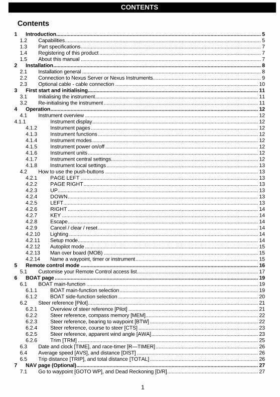
Contents1 Introduction.............................................................................................................................................. 5
1.2 Capabilities........................................................................................................................................ 51.3 Part specifications............................................................................................................................. 71.4 Registering of this product ................................................................................................................ 71.5 About this manual ............................................................................................................................. 7
2 Installation................................................................................................................................................ 82.1 Installation general ............................................................................................................................ 82.2 Connection to Nexus Server or Nexus Instruments........................................................................... 92.3 Optional cable - cable connection ................................................................................................... 10
3 First start and initialising...................................................................................................................... 113.1 Initialising the instrument................................................................................................................. 113.2 Re-initialising the instrument ........................................................................................................... 11
4 Operation................................................................................................................................................ 124.1 Instrument overview ........................................................................................................................ 12
4.1.1 Instrument display................................................................................................................... 124.1.2 Instrument pages.................................................................................................................... 124.1.3 Instrument functions ............................................................................................................... 124.1.4 Instrument modes................................................................................................................... 124.1.5 Instrument power on/off .......................................................................................................... 124.1.6 Instrument units ...................................................................................................................... 124.1.7 Instrument central settings...................................................................................................... 124.1.8 Instrument local settings ......................................................................................................... 13
4.2 How to use the push-buttons .......................................................................................................... 134.2.1 PAGE LEFT ........................................................................................................................... 134.2.2 PAGE RIGHT......................................................................................................................... 134.2.3 UP........................................................................................................................................... 134.2.4 DOWN.................................................................................................................................... 134.2.5 LEFT....................................................................................................................................... 134.2.6 RIGHT .................................................................................................................................... 144.2.7 KEY ........................................................................................................................................ 144.2.8 Escape.................................................................................................................................... 144.2.9 Cancel / clear / reset ............................................................................................................... 144.2.10 Lighting ................................................................................................................................... 144.2.11 Setup mode............................................................................................................................. 144.2.12 Autopilot mode ........................................................................................................................ 154.2.13 Man over board (MOB) ........................................................................................................... 154.2.14 Name a waypoint, timer or instrument..................................................................................... 15
5 Remote control mode ........................................................................................................................... 165.1 Customise your Remote Control access list.................................................................................... 17
6 BOAT page ............................................................................................................................................. 196.1 BOAT main-function ....................................................................................................................... 19
6.1.1 BOAT main-function selection................................................................................................ 196.1.2 BOAT side-function selection ................................................................................................. 20
6.2 Steer reference [Pilot]...................................................................................................................... 216.2.1 Overview of steer reference [Pilot] .......................................................................................... 216.2.2 Steer reference, compass memory [MEM].............................................................................. 226.2.3 Steer reference, bearing to waypoint [BTW] ........................................................................... 226.2.4 Steer reference, course to steer [CTS] ................................................................................... 236.2.5 Steer reference, apparent wind angle [AWA].......................................................................... 236.2.6 Trim [TRM] ............................................................................................................................. 25
6.3 Date and clock [TIME], and race-timer [R—TIMER]....................................................................... 266.4 Average speed [AVS], and distance [DIST] .................................................................................... 266.5 Trip distance [TRIP], and total distance [TOTAL] ........................................................................... 26
7 NAV page (Optional).............................................................................................................................. 277.1 Go to waypoint [GOTO WP], and Dead Reckoning [D/R]............................................................... 27
CONTENTS

2
7.2 Combi steer including COG, SOG, BTW, DTW, and course deviation...........................................277.3 Cross track error [XTE], and course to steer [CTS], wp. closure velocity [WCV]............................ 287.4 Time to go [TTG], and estimated time of arrival [ETA] .................................................................... 287.5 Position in latitude / longitude, and satellite status .......................................................................... 28
8 WP page (Optional) ............................................................................................................................... 298.1 Mark waypoint [MARK WP], and set waypoint [SET WP]............................................................... 298.2 Edit waypoint [EDIT WP], and view waypoint [VIEW WP].............................................................. 308.3 Copy waypoint [COPY WP] ............................................................................................................ 318.4 Move waypoint [MOVE WP]............................................................................................................ 318.5 Delete waypoint [DELETE].............................................................................................................. 318.6 Methods to search for a waypoint.................................................................................................... 31
8.6.1 Search a waypoint in numerical order ..................................................................................... 318.6.2 Search for a waypoint in alphabetical order............................................................................. 32
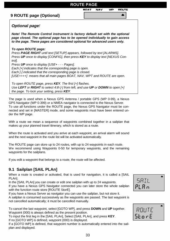
9 ROUTE page (Optional) ........................................................................................................................ 339.1 Sailplan [SAIL PLAn]....................................................................................................................... 33
9.1.1 Cancel a sail plan [CLEAR PLAn]........................................................................................... 349.1.2 Insert a LEG in the sail plan [INSERT] ................................................................................... 349.1.3 Cancel a LEG in the sail plan.................................................................................................. 35
9.2 Store a route [ROUTE StorE].......................................................................................................... 359.3 Route call [ROUTE CALL] .............................................................................................................. 359.4 Reverse route call [REVERSE CALL]............................................................................................. 359.5 Delete a route [DELETE]................................................................................................................. 35
10 Man Over Board [MOB] function ..................................................................................................... 3611 Autopilot mode .................................................................................................................................. 37
11.1 Switch between instrument mode and autopilot mode ................................................................ 3711.2 Standby mode............................................................................................................................. 3711.3 Autopilot functions ...................................................................................................................... 37
11.3.1 Activate automatic steering................................................................................................. 3711.3.2 Turn off automatic steering................................................................................................. 3811.3.3 Automatic steering by compass [HDG]............................................................................... 3811.3.4 Automatic steering by navigator [NAV] ............................................................................... 3811.3.5 Automatic steering by wind angle [AWA]............................................................................ 3911.3.6 Power steering [PWR]........................................................................................................ 4011.3.7 Dodging and returning to last steering function .................................................................. 40
12 Setup mode....................................................................................................................................... 4112.1 Setup mode................................................................................................................................. 41
12.1.1 The setup mode is divided in 7 setup groups ..................................................................... 4112.1.2 How to access setup mode and setup group...................................................................... 4112.1.3 How to change a setting ..................................................................................................... 4112.1.4 How to return to previous mode .......................................................................................... 4112.1.5 Factory default settings....................................................................................................... 41
12.2 Alarm setup group [ALARMS]..................................................................................................... 4112.2.1 General depth alarm information......................................................................................... 4212.2.2 Set and turn on shallow alarm [SHALLOW] ....................................................................... 4212.2.3 Set and turn on depth alarm [DEEP] .................................................................................. 4212.2.4 Cancel an alarm value ........................................................................................................ 4212.2.5 Silencing an alarm .............................................................................................................. 4212.2.6 Turning off an alarm ........................................................................................................... 4212.2.7 Off course alarm limit [OCA -- LIM] .................................................................................... 4212.2.8 Pilot off course alarm [PCA] ............................................................................................... 4312.2.9 Watch-out timer alarm [W-TIMER]..................................................................................... 4312.2.10 The 8 named timer alarms [TIMERS]................................................................................. 4312.2.11 Navigation arrival alarm [NAV-ALM] ................................................................................... 43
12.3 Damping setup group [DAMPING] ............................................................................................. 4412.3.1 Damping of boat speed through the water [SPEED]........................................................... 4512.3.2 Damping of compass heading [COMPASS]....................................................................... 4512.3.3 Damping of wind angle and wind speed [WIND] ................................................................ 45
CONTENTS
3
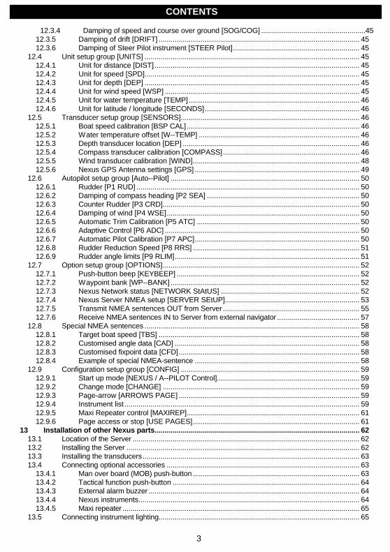
12.3.4 Damping of speed and course over ground [SOG/COG] ....................................................4512.3.5 Damping of drift [DRIFT] .................................................................................................... 4512.3.6 Damping of Steer Pilot instrument [STEER Pilot]............................................................... 45
12.4 Unit setup group [UNITS] ........................................................................................................... 4512.4.1 Unit for distance [DIST] ...................................................................................................... 4512.4.2 Unit for speed [SPD]........................................................................................................... 4512.4.3 Unit for depth [DEP] ........................................................................................................... 4512.4.4 Unit for wind speed [WSP] ................................................................................................. 4512.4.5 Unit for water temperature [TEMP]..................................................................................... 4612.4.6 Unit for latitude / longitude [SECONDS]............................................................................. 46
12.5 Transducer setup group [SENSORS]......................................................................................... 4612.5.1 Boat speed calibration [BSP CAL] ...................................................................................... 4612.5.2 Water temperature offset [W--TEMP] ................................................................................ 4612.5.3 Depth transducer location [DEP] ........................................................................................ 4612.5.4 Compass transducer calibration [COMPASS].................................................................... 4612.5.5 Wind transducer calibration [WIND]................................................................................... 4812.5.6 Nexus GPS Antenna settings [GPS] .................................................................................. 49
12.6 Autopilot setup group [Auto--Pilot] .............................................................................................. 5012.6.1 Rudder [P1 RUD] ............................................................................................................... 5012.6.2 Damping of compass heading [P2 SEA] ............................................................................ 5012.6.3 Counter Rudder [P3 CRD].................................................................................................. 5012.6.4 Damping of wind [P4 WSE]................................................................................................ 5012.6.5 Automatic Trim Calibration [P5 ATC] ................................................................................. 5012.6.6 Adaptive Control [P6 ADC] ................................................................................................. 5012.6.7 Automatic Pilot Calibration [P7 APC].................................................................................. 5012.6.8 Rudder Reduction Speed [P8 RRS] ................................................................................... 5112.6.9 Rudder angle limits [P9 RLIM]............................................................................................ 51
12.7 Option setup group [OPTIONS].................................................................................................. 5212.7.1 Push-button beep [KEYBEEP] ........................................................................................... 5212.7.2 Waypoint bank [WP--BANK] .............................................................................................. 5212.7.3 Nexus Network status [NETWORK StAtUS] ..................................................................... 5212.7.4 Nexus Server NMEA setup [SERVER SEtUP]................................................................... 5312.7.5 Transmit NMEA sentences OUT from Server .................................................................... 5512.7.6 Receive NMEA sentences IN to Server from external navigator ......................................... 57
12.8 Special NMEA sentences ........................................................................................................... 5812.8.1 Target boat speed [TBS] .................................................................................................... 5812.8.2 Customised angle data [CAD] ............................................................................................ 5812.8.3 Customised fixpoint data [CFD].......................................................................................... 5812.8.4 Example of special NMEA-sentence .................................................................................. 58
12.9 Configuration setup group [CONFIG] ......................................................................................... 5912.9.1 Start up mode [NEXUS / A--PILOT Control]....................................................................... 5912.9.2 Change mode [CHANGE] .................................................................................................. 5912.9.3 Page-arrow [ARROWS PAGE] .......................................................................................... 5912.9.4 Instrument list ..................................................................................................................... 5912.9.5 Maxi Repeater control [MAXIREP]...................................................................................... 6112.9.6 Page access or stop [USE PAGES]................................................................................... 61
13 Installation of other Nexus parts...................................................................................................... 6213.1 Location of the Server ................................................................................................................. 6213.2 Installing the Server .................................................................................................................... 6213.3 Installing the transducers............................................................................................................ 6313.4 Connecting optional accessories ................................................................................................ 63
13.4.1 Man over board (MOB) push-button ................................................................................... 6313.4.2 Tactical function push-button ............................................................................................. 6413.4.3 External alarm buzzer ......................................................................................................... 6413.4.4 Nexus instruments.............................................................................................................. 6413.4.5 Maxi repeater ...................................................................................................................... 65
13.5 Connecting instrument lighting.................................................................................................... 65
CONTENTS
4
13.6 Connecting a NMEA instrument IN to the Server ........................................................................6513.7 Connecting a NMEA instrument OUT from Server ..................................................................... 6513.8 Connecting the power supply...................................................................................................... 6613.9 Compatibility with our previous transducers................................................................................ 67
13.9.1 Log transducer.................................................................................................................... 6713.9.2 Depth transducer................................................................................................................ 6813.9.3 Wind transducer................................................................................................................. 6813.9.4 Compass transducer .......................................................................................................... 6913.9.5 GPS transducer.................................................................................................................. 6913.9.6 NMEA transducers ............................................................................................................. 69
14 Maintenance and fault finding.......................................................................................................... 7014.1 Maintenance................................................................................................................................ 7014.2 Fault finding ................................................................................................................................ 70
14.2.1 General............................................................................................................................... 7014.2.2 What you should know about digital depth sounders.......................................................... 70
14.3 Fault - action ............................................................................................................................... 7114.4 Nexus Network error messages with cause and remedy ............................................................ 73
15 Specifications .................................................................................................................................... 7515.1 Technical specifications.............................................................................................................. 7515.2 Nexus Network specification....................................................................................................... 7515.3 Optional accessories................................................................................................................... 7615.4 Abbreviations .............................................................................................................................. 7815.5 Warranty ..................................................................................................................................... 81
5
1 Introduction
1.1 Welcome aboard!Thank you for choosing a Nexus Remote Control instrument. Through this manual we would like to help you toinstall and operate your Nexus product. We are convinced that you will appreciate the useful functions weatheryou are a cruiser or a racer. To get the most out of your Nexus product, please read through this manualcarefully before you start your installation. If you see us at a show, stop by and say hello.
Good luck and happy boating!
1.2 CapabilitiesThe Server is the ”heart” of your Nexus Network, to which transducers for speed, depth, heading, wind andnavigation (GPS, Loran or Decca) are connected.
From the Server, the single Nexus data bus cable carries power and data to the instruments, which arerepeaters of the information sent from the Server.
Your Remote Control instrument can be connected directly to a Nexus instrument on the Nexus Network, orto the Nexus Server, and if so you do not have to re-calibrate the transducers or your current Nexus Networksetup.
The Remote Control instrument is more than just a remote control:
• It is a Nexus Multi function instrument in itself, displaying all functions in your Network.
• It can remote control all, or selected Nexus instruments in your Network.
• It can be used at the chart table as the waypoint and rout editor in your Network
• It can be an integrated control unit for the Nexus Autopilot.
• It offers unique trim functions for the sailor.
• It offers a Man Overboard function.
• It offers a built in alarm with eight alarm settings.
• It offers a control of the MAXI repeaters, up to nine units.
• It offers the possibility to customise the display with your two favourite functions.
• It can be configured to ”hide” pages you do not want to use, or conceal from curious hands.
The optional cable - cable connection (Art. No. 20966) gives you the flexibility to use it anywhere on yourboat. Simply disconnect it, and take it to your navigation table.
INTRODUCTION
6
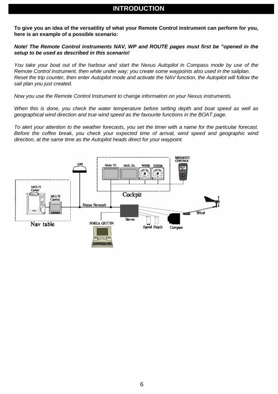
To give you an idea of the versatility of what your Remote Control instrument can perform for you,here is an example of a possible scenario:
Note! The Remote Control instruments NAV, WP and ROUTE pages must first be ”opened in thesetup to be used as described in this scenario!
You take your boat out of the harbour and start the Nexus Autopilot in Compass mode by use of theRemote Control instrument, then while under way; you create some waypoints also used in the sailplan.Reset the trip counter, then enter Autopilot mode and activate the NAV function, the Autopilot will follow thesail plan you just created.
Now you use the Remote Control Instrument to change information on your Nexus instruments.
When this is done, you check the water temperature before setting depth and boat speed as well asgeographical wind direction and true wind speed as the favourite functions in the BOAT page.
To alert your attention to the weather forecasts, you set the timer with a name for the particular forecast.Before the coffee break, you check your expected time of arrival, wind speed and geographic winddirection, at the same time as the Autopilot heads direct for your waypoint.
INTRODUCTION
7
1.3 Part specificationsNexus Remote Control instrument is delivered with all parts for mounting.Check prior to installation.
Qty. Description 1 Remote Control Instrument with 5m (16 ft) cable1 Instrument bracket3 Mounting screws for the instrument bracket5 Wire protectors 0,25 mm (1/100”)1 Installation and operation manual1 Warranty card1 National distributors list
1.4 Registering of this productOnce you have checked that you have all the listed parts, please take time to fill in the warranty document andreturn it to your national distributor.
By returning this document, it will assist your distributor to give you prompt and expert attention, in the event ofyour experiencing difficulties with this product. Keep your proof of purchase. Also, your details are added toour customer database so that you automatically receive new product catalogues as and when they arereleased.
1.5 About this manual • Each time a push-button is referred to in this manual, the push-button name is written in bold and
CAPITAL letters e.g. PAGE RIGHT.
• Unless otherwise stated, the push-button presses are momentary.
• Each time a function is mentioned in the text, it will be in brackets and in the same format, where possible,as displayed, e.g. [Lat].
• With the word navigator we mean a GPS, Loran or Decca instrument.
• Which instrument is navigating? By the term navigating, we mean the active instrument in which thewaypoint memory is used for navigation to calculate the navigation data, i.e. BTW, DTW etc. There canonly be one instrument on the Nexus Network, which is keeping the waypoints in memory, but thewaypoints can be reached from all instruments.
• Functions followed by the text ”optional" are not valid in factory default setting. See setup mode to be ableto display and use these functions.
Note! We have put in a lot of effort, in order to make this manual correct and complete. However, since wehave a policy of continuous improvement, some information may differ from the product functions. If you needfurther information, contact your national distributor.
INTRODUCTION
8
2 Installation
2.1 Installation generalReliable and accurate operation of marine electronics depends very much on correct installation. Please readand fully understand the installation requirements before attempting installation.
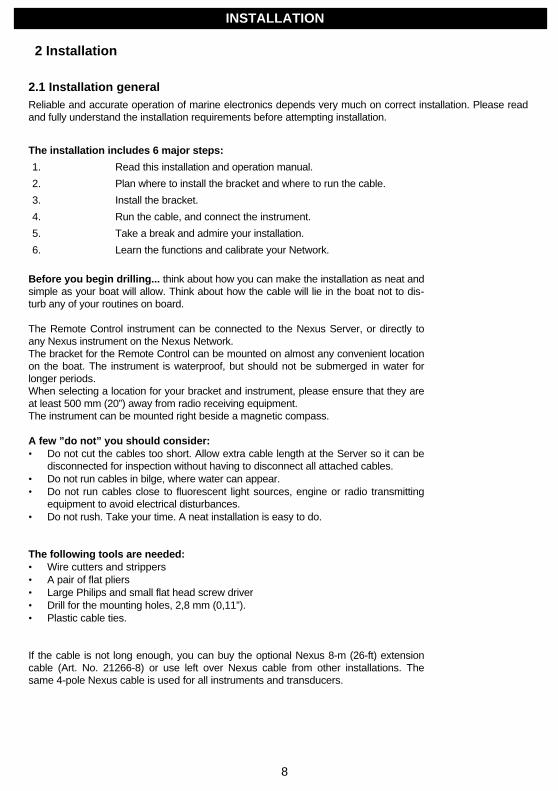
The installation includes 6 major steps:
1. Read this installation and operation manual.
2. Plan where to install the bracket and where to run the cable.
3. Install the bracket.
4. Run the cable, and connect the instrument.
5. Take a break and admire your installation.
6. Learn the functions and calibrate your Network.
Before you begin drilling... think about how you can make the installation as neat andsimple as your boat will allow. Think about how the cable will lie in the boat not to dis-turb any of your routines on board.
The Remote Control instrument can be connected to the Nexus Server, or directly toany Nexus instrument on the Nexus Network.The bracket for the Remote Control can be mounted on almost any convenient locationon the boat. The instrument is waterproof, but should not be submerged in water forlonger periods.When selecting a location for your bracket and instrument, please ensure that they areat least 500 mm (20”) away from radio receiving equipment.The instrument can be mounted right beside a magnetic compass.
A few ”do not” you should consider:• Do not cut the cables too short. Allow extra cable length at the Server so it can be
disconnected for inspection without having to disconnect all attached cables.• Do not run cables in bilge, where water can appear.• Do not run cables close to fluorescent light sources, engine or radio transmitting
equipment to avoid electrical disturbances.• Do not rush. Take your time. A neat installation is easy to do.
The following tools are needed:• Wire cutters and strippers• A pair of flat pliers• Large Philips and small flat head screw driver• Drill for the mounting holes, 2,8 mm (0,11”).• Plastic cable ties.
If the cable is not long enough, you can buy the optional Nexus 8-m (26-ft) extensioncable (Art. No. 21266-8) or use left over Nexus cable from other installations. Thesame 4-pole Nexus cable is used for all instruments and transducers.
INSTALLATION
9
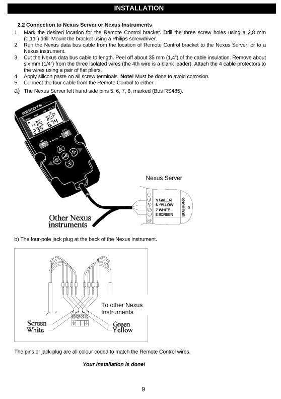
2.2 Connection to Nexus Server or Nexus Instruments1 Mark the desired location for the Remote Control bracket. Drill the three screw holes using a 2,8 mm
(0,11”) drill. Mount the bracket using a Philips screwdriver.2 Run the Nexus data bus cable from the location of Remote Control bracket to the Nexus Server, or to a
Nexus instrument.3 Cut the Nexus data bus cable to length. Peel off about 35 mm (1,4”) of the cable insulation. Remove about
six mm (1/4”) from the three isolated wires (the 4th wire is a blank leader). Attach the 4 cable protectors tothe wires using a pair of flat pliers.
4 Apply silicon paste on all screw terminals. Note! Must be done to avoid corrosion.5 Connect the four cable from the Remote Control to either:
a) The Nexus Server left hand side pins 5, 6, 7, 8, marked (Bus RS485).
b) The four-pole jack plug at the back of the Nexus instrument.
The pins or jack-plug are all colour coded to match the Remote Control wires.
Your installation is done!
To other NexusInstruments
INSTALLATION
Nexus Server

10
2.2.1 Optional cable - cable connection
The optional connector (Art. No. 20966) allows you the flexibility to disconnect the Remote Control to use it ata second location on the boat.In this case the optional bracket (Art. No. 21218-1) is handy to use.Further the optional eight metres (26 ft) Nexus data bus cable (Art. No. 21266-8 ) can be supplied by themetre.
Note! For other connections, see chapter ”Connection of other Nexus parts”.
To Nexus Serveror other Nexusinstrument
INSTALLATION
Optional connector(Art. No. 20966)

11
3 First start and initialising
3.1 Initialising the instrumentAt power on, the instrument will perform a self-test, during which the display will firstshow all segments, then the version number and the Nexus Network ID number.
To initialise the instrument, press KEY on all installed digital instruments, one at a time.
Note: Always wait for the text ”Init OK” to be displayed, before you press KEYon the next instrument!
The Nexus Server is automatically given ID number 0 (ID numbers 0 - 15 is reservedfor transducers. Therefore the first given ID number is 16, then 17 and so on. The or-der in which you press KEY is the same order as the instruments will be given an IDnumber on the Nexus Network.
The drawing shows that the instrument version number is 1.0 and the given ID numberis 18.
3.2 Re-initialising the instrumentIf two instruments by mistake have the same ID number, this can cause disturbanceand block the information on the Nexus Network.
To re-initialise the instrument, press DOWN and UP together during the power up se-quence when version and ID numbers are displayed.
The instrument self-test is then re-started on all instruments and you will be asked to(KEY PRESS) on each instrument as explained above.
FIRST START AND INITIALISING
12
4 Operation
4.1 Instrument overview
4.1.1 Instrument display
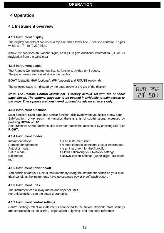
The display consists of two lines, a top-line and a lower-line. Each line contains 7 digitswhich are 7 mm (0.27”) high.
Above the two lines are various signs, or flags, to give additional information. (2D or 3Dnavigation from the GPS etc.)
4.1.2 Instrument pages
The Remote Control instrument has its functions divided on 4 pages.The page names are printed above the display:
BOAT (default), NAV (optional), WP (optional) and ROUTE (optional).
The selected page is indicated by the page-arrow at the top of the display.
Note! The Remote Control instrument is factory default set with the optionalpage closed. The optional page has to be opened individually to gain access tothe page. These pages are considered optional for advanced users only.
4.1.3 Instrument functions
Main-function: Each page has a main-function, displayed when you select a new page.Sub-function: Under each main-function there is a list of sub-functions, accessed bypressing DOWN or UP.Side-function: Some functions also offer side-functions, accessed by pressing LEFT orRIGHT.
4.1.4 Instrument modes
Instrument mode: It is an instrument itself.Remote control mode: It remote controls connected Nexus instruments.Autopilot mode: It is an instrument for the Autopilot.Setup mode: It allows calibrating your Network settings.Edit mode: It allows editing settings (when digits are flash-ing).
4.1.5 Instrument power on/off
You switch on/off your Nexus instruments by using the instrument switch on your elec-trical panel, as the instruments have no separate power on/off push-button.
4.1.6 Instrument units
The instrument can display metric and imperial units.For unit selection, see the setup group units.
4.1.7 Instrument central settings
Central settings affect all instruments connected to the Nexus Network. Most settingsare central such as ”clear trip”, ”depth alarm”, ”lighting” and ”set steer reference”
OPERATION
13
4.1.8 Instrument local settings
Local settings affect only the instrument in which it is set. When a setting is local wehave listed this after the setting. Typical local settings are ”boat speed dampening” and”units”. These settings will not be transferred to other instruments on the Nexus Net-work.
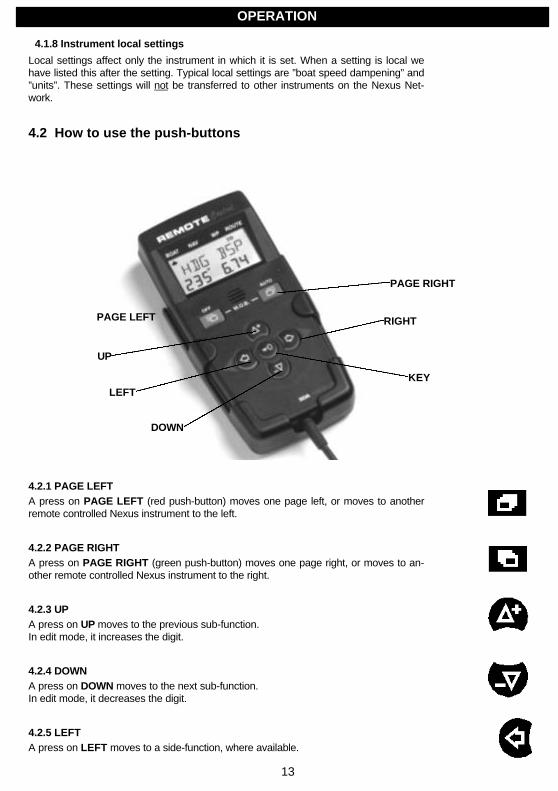
4.2 How to use the push-buttons
4.2.1 PAGE LEFTA press on PAGE LEFT (red push-button) moves one page left, or moves to anotherremote controlled Nexus instrument to the left.
4.2.2 PAGE RIGHTA press on PAGE RIGHT (green push-button) moves one page right, or moves to an-other remote controlled Nexus instrument to the right.
4.2.3 UPA press on UP moves to the previous sub-function.In edit mode, it increases the digit.
4.2.4 DOWNA press on DOWN moves to the next sub-function.In edit mode, it decreases the digit.
4.2.5 LEFTA press on LEFT moves to a side-function, where available.
OPERATION
PAGE LEFT
LEFT
DOWN
RIGHT
KEY
UP
PAGE RIGHT
14
In edit mode, LEFT moves the cursor one step to the left.
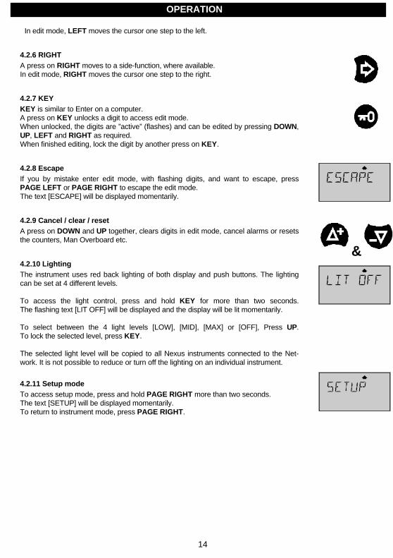
4.2.6 RIGHTA press on RIGHT moves to a side-function, where available.In edit mode, RIGHT moves the cursor one step to the right.
4.2.7 KEYKEY is similar to Enter on a computer.A press on KEY unlocks a digit to access edit mode.When unlocked, the digits are ”active” (flashes) and can be edited by pressing DOWN,UP, LEFT and RIGHT as required.When finished editing, lock the digit by another press on KEY.
4.2.8 EscapeIf you by mistake enter edit mode, with flashing digits, and want to escape, pressPAGE LEFT or PAGE RIGHT to escape the edit mode.The text [ESCAPE] will be displayed momentarily.
4.2.9 Cancel / clear / resetA press on DOWN and UP together, clears digits in edit mode, cancel alarms or resetsthe counters, Man Overboard etc.
4.2.10 LightingThe instrument uses red back lighting of both display and push buttons. The lightingcan be set at 4 different levels.
To access the light control, press and hold KEY for more than two seconds.The flashing text [LIT OFF] will be displayed and the display will be lit momentarily.
To select between the 4 light levels [LOW], [MID], [MAX] or [OFF], Press UP.To lock the selected level, press KEY.
The selected light level will be copied to all Nexus instruments connected to the Net-work. It is not possible to reduce or turn off the lighting on an individual instrument.
4.2.11 Setup modeTo access setup mode, press and hold PAGE RIGHT more than two seconds.The text [SETUP] will be displayed momentarily.To return to instrument mode, press PAGE RIGHT.
OPERATION
&
15
4.2.12 Autopilot mode
To change between instrument mode and Autopilot mode, press PAGE LEFT andPAGE RIGHT together.
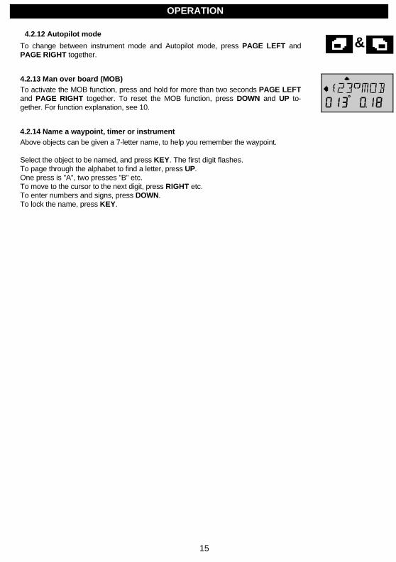
4.2.13 Man over board (MOB)To activate the MOB function, press and hold for more than two seconds PAGE LEFTand PAGE RIGHT together. To reset the MOB function, press DOWN and UP to-gether. For function explanation, see 10.
4.2.14 Name a waypoint, timer or instrumentAbove objects can be given a 7-letter name, to help you remember the waypoint.
Select the object to be named, and press KEY. The first digit flashes.To page through the alphabet to find a letter, press UP.One press is ”A”, two presses ”B” etc.To move to the cursor to the next digit, press RIGHT etc.To enter numbers and signs, press DOWN.To lock the name, press KEY.
OPERATION
&
16
5 Remote control mode
At the first power up, you automatically enter instrument mode and BOAT page.
When the Remote Control instrument is connected to the Nexus Network and initial-ised, all Nexus digital instruments connected to the Nexus Network are automaticallydetected by the Remote Control instrument and can now be remote controlled.
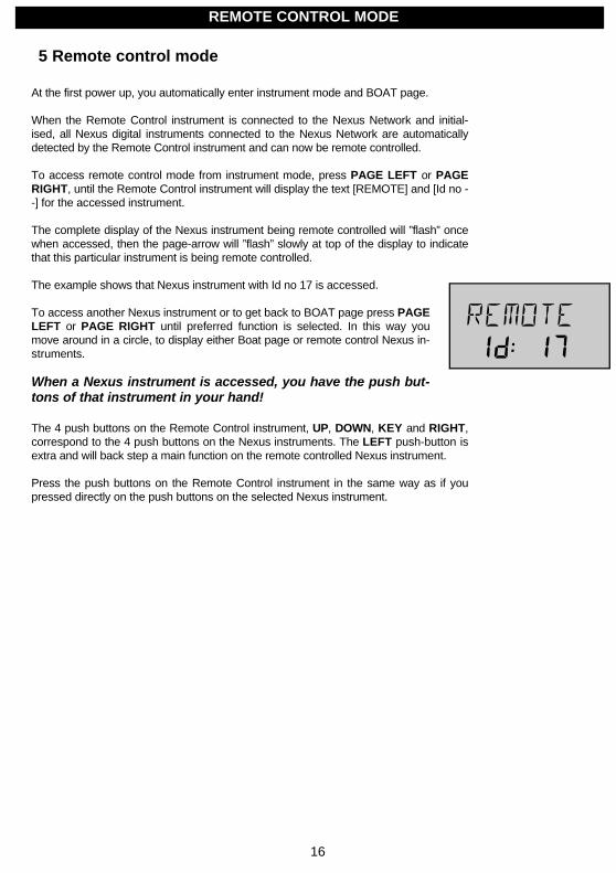
To access remote control mode from instrument mode, press PAGE LEFT or PAGERIGHT, until the Remote Control instrument will display the text [REMOTE] and [Id no --] for the accessed instrument.
The complete display of the Nexus instrument being remote controlled will ”flash” oncewhen accessed, then the page-arrow will ”flash” slowly at top of the display to indicatethat this particular instrument is being remote controlled.
The example shows that Nexus instrument with Id no 17 is accessed.
To access another Nexus instrument or to get back to BOAT page press PAGELEFT or PAGE RIGHT until preferred function is selected. In this way youmove around in a circle, to display either Boat page or remote control Nexus in-struments.
When a Nexus instrument is accessed, you have the push but-tons of that instrument in your hand!
The 4 push buttons on the Remote Control instrument, UP, DOWN, KEY and RIGHT,correspond to the 4 push buttons on the Nexus instruments. The LEFT push-button isextra and will back step a main function on the remote controlled Nexus instrument.
Press the push buttons on the Remote Control instrument in the same way as if youpressed directly on the push buttons on the selected Nexus instrument.
REMOTE CONTROL MODE

17
5.1 Customise your Remote Control access listWhen you connect the Remote Control instrument to the Nexus Network, it automati-cally detects all Nexus digital instruments and will display them with the text [REMOTEId #] in ID number access order.
You may customise your Remote Control instrument to create your own access order ofNexus digital instruments and to name them for easier recognition. You may also ex-clude access of the instruments that you can not see or simply want to limit access to.Note! This is an optional function for advanced users.
Proceed as follows:1. Make a note of each instrument's Id number, seen during the power up procedure.
Note the Id numbers in the order you want them to be accessed (not in Id numberorder). Exclude Id numbers of those instruments you do not want to access.
2. Enter setup mode:Press and hold PAGE RIGHT until text [SETUP] is displayed.
1. Find [CONFIG]: Press UP to find function [CONFIG] and press KEY.
2. Find [EDIT List]: Press UP until you find function [EDIT LiSt], and press KEY to enter the end of
the list.
1. Press UP to go to the next instrument in the list. Access order number isdisplayed in the lower left corner. If you want to add an instrument to the list, pressKEY.The first line ”_” of the 7 lines ”_ _ _ _ _ _ _” now flashes.
2. To name the first instrument:To enter characters, press UP or DOWN. To move to next character, pressRIGHT.When the name is entered, lock it with KEY.
1. Enter the Id number of the instrument in the lower right corner and press KEY tolock it.
2. Repeat steps 5 to 7 for all instruments you want to have included in the list.
3. To exit [EDIT LiSt] press PAGE RIGHT.
1. Set [USELIST] to [On]:Press UP to [USELIST], if [USELIST] is [OFF] press KEY, then press UP tochange to [On] and press KEY to lock.
Now your customised list is used instead of the complete list. If you need to remotecontrol all instruments again, set [USELIST] to [OFF] an all instruments will be acces-sible.
To exclude an instrument from the list, when in [EDIT List] press UP and DOWN to-gether when the instrument Id number is displayed.
Note! In setup mode and under [CONFIG] group, you can create an instrument list witha combination of the following 3 functions:[MAKE LiSt, YES/no], to make a list of all connected instruments in Id number order.[EDIT LiSt], to create a new list, or edit an existing list.
REMOTE CONTROL MODE

18
[USELIST On/OFF], to activate / de-activate the customised user list.
19
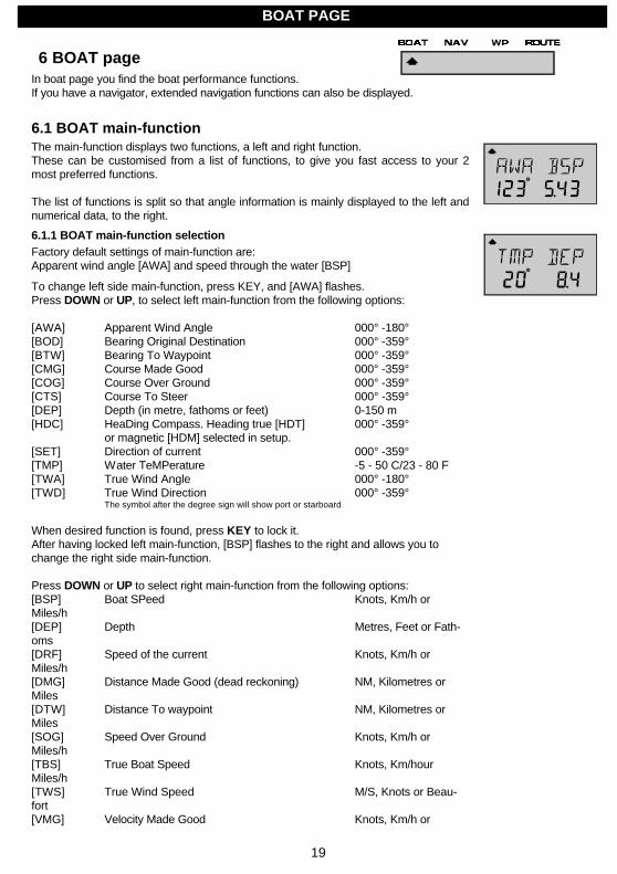
6 BOAT pageIn boat page you find the boat performance functions.If you have a navigator, extended navigation functions can also be displayed.
6.1 BOAT main-functionThe main-function displays two functions, a left and right function.These can be customised from a list of functions, to give you fast access to your 2most preferred functions.
The list of functions is split so that angle information is mainly displayed to the left andnumerical data, to the right.
6.1.1 BOAT main-function selectionFactory default settings of main-function are:Apparent wind angle [AWA] and speed through the water [BSP]
To change left side main-function, press KEY, and [AWA] flashes.Press DOWN or UP, to select left main-function from the following options:
[AWA] Apparent Wind Angle 000° -180°[BOD] Bearing Original Destination 000° -359°[BTW] Bearing To Waypoint 000° -359°[CMG] Course Made Good 000° -359°[COG] Course Over Ground 000° -359°[CTS] Course To Steer 000° -359°[DEP] Depth (in metre, fathoms or feet) 0-150 m[HDC] HeaDing Compass. Heading true [HDT] 000° -359°
or magnetic [HDM] selected in setup.[SET] Direction of current 000° -359°[TMP] Water TeMPerature -5 - 50 C/23 - 80 F[TWA] True Wind Angle 000° -180°[TWD] True Wind Direction 000° -359°
The symbol after the degree sign will show port or starboard
When desired function is found, press KEY to lock it.After having locked left main-function, [BSP] flashes to the right and allows you tochange the right side main-function.
Press DOWN or UP to select right main-function from the following options:[BSP] Boat SPeed Knots, Km/h orMiles/h[DEP] Depth Metres, Feet or Fath-oms[DRF] Speed of the current Knots, Km/h orMiles/h[DMG] Distance Made Good (dead reckoning) NM, Kilometres orMiles[DTW] Distance To waypoint NM, Kilometres orMiles[SOG] Speed Over Ground Knots, Km/h orMiles/h[TBS] True Boat Speed Knots, Km/hourMiles/h[TWS] True Wind Speed M/S, Knots or Beau-fort[VMG] Velocity Made Good Knots, Km/h or
BOAT PAGE

20
Miles/h[WCV] Waypoint Closure Velocity Knots, Km/h orMiles/h[XTE] Cross Track Error NM, Kilometres orMiles[AWS] Apparent Wind Speed M/S, Knots or Beau-fort[BAT] BATtery voltage, measured at Server VoltWhen desired function is found, press KEY to lock it.
6.1.2 BOAT side-function selection
To access BOAT side-function, press LEFT or RIGHT, to toggle between main-function and side function.
Factory default settings of side-function are:Water temperature in C° [TMP] and depth in metres [DEP] in the other.
To change left side-function, press KEY, and [TMP] flashes.Press DOWN or UP, to select left side-function from the same list as in main-function.
When desired function is found, press KEY to lock it.After having locked left side-function, [DEP] flashes to the right and allows you tochange the right side-function.
Press DOWN or UP to select right side-function from the same list as in main-function.
When desired function is found, press KEY to lock it.
BOAT PAGE

21
6.2 Steer reference [Pilot]The sub-function [Pilot] is intended for use together with the optional analogue instru-ment Steer Pilot (Art no 20550-2) to assist the helmsman to keep the desired heading.The same function is also used in the Compass Data instrument (Art. No. 21487).
When a steer reference has been selected, the analogue Steer Pilot instrument isautomatically activated. It starts to indicate the difference between desired and actualheading and angle. The logic is to keep the Steer Pilot instrument needle straight uppointing at 0 (zero) to stay on the set heading.
In analogue Steer Pilot instruments from version 2.0, [MEM] and [BTW] is functioningwith COG (if navigator connected) even if a compass is not installed. The analogueread out will start at speed above 4 KTS and stop below 2 KTS.
If you do not have the analogue Steer Pilot instrument, you can still use the function ifyou display the selected steer reference heading [Str] in the sub-function and compareit with the actual compass heading in the main-function in the Nexus Multi Control in-strument.
A Nexus Autopilot can not be activated from the steer reference function. But when theNexus Autopilot has been activated in compass or wind mode it is possible to alter theAutopilot heading from the [MEM] and [AWA] functions.
The last used steer reference function will be stored in memory and automatically acti-vated at power on. (Available from Nexus Server version 2.6).
6.2.1 Overview of steer reference [Pilot]
Steer reference Function Type Text on dis-play[MEM] Compass heading Setable MEM
stored in 1, or 2memories [TAC]
[BTW] Bearing to waypoint Automatic WP[CTS] Course to steer to Automatic MEM WP
waypoint, correctedfor drift and current
[AWA] Apparent wind angle Settable WIND[OFF] Steer Pilot off
When any steer reference function is activated, the text on the display will be copiedand shown on all Nexus Multi XL and Multi Control instruments in your Nexus Network.
BOAT PAGE
22
6.2.2 Steer reference, compass memory [MEM]This function requires a Nexus or NMEA compass transducer. The function displaysthe deviation from a set compass course value. When the optional analogue Steer Pilotinstrument or a Compass Data instrument is connected, it will display the differencefrom the set course and the actual heading.
The function is semi automatic, i.e. when activated, present compass heading is copiedto memory. You can later change the value manually.
Select sub-function [Pilot], press KEY. The text [OFF] or the last selected steer refer-ence function flashes.To select steer reference [MEM], press UP.To activate the function, press KEY. MEM is shown on the Multi Control display. The100th digit for present compass course flashes. If the course is OK, and you want toconfirm the value, press KEY to lock it.To set your own value, press DOWN, UP and RIGHT as required.To lock the value, press KEY.
Note! Steer reference heading value [MEM] can also be selected directly from an op-tional trim push-button (Art. No. 19763) connected to the Nexus Server, without firstselecting [MEM] in [Pilot OFF] function. (Available from Nexus Server version 1.9.)
6.2.3 Steer reference, bearing to waypoint [BTW]This function requires a Nexus or NMEA compass transducer and a Nexus GPS orNMEA navigator. When selected, the function displays [BTW] and the analogue SteerPilot instrument displays the difference between the compass heading and the [BTW].
The function can only be displayed if the connected navigator is navigating towards awaypoint. Since the navigator controls the displayed value, the value can not be altered.
Select sub-function [Pilot], press KEY.The text [OFF] or the last selected steer reference function flashes.To select steer reference [BTW], press UP.To activate the function, press KEY. [WP] is shown on the Multi Control / XL display.The sub-function [Str] automatically displays the stored [BTW] value.
BOAT PAGE
23
6.2.4 Steer reference, course to steer [CTS]The function requires log transducer, a Nexus or NMEA compass transducer and aNexus GPS or NMEA navigator. When selected, the function displays [CTS] and theanalogue Steer Pilot instrument displays the difference between the compass headingand [CTS] including set and drift.
The function can only be displayed if the connected navigator is navigating towards awaypoint. Since the navigator controls the displayed value, the value can not be altered.
The function is compensated for set and drift, by using compass heading, boat speedthrough the water, course and speed over ground [COG/SOG] and bearing to waypoint[BTW].
Select sub-function [Pilot], press KEY.The text [OFF] or the last selected steer reference function flashes.To select steer reference [CTS], press UP.To activate the function, press KEY. [MEM WP] is lit on the display.The sub-function [Str] automatically displays the stored [CTS] value.
The function is invaluable when you want to sail the shortest distance to a waypoint.
6.2.5 Steer reference, apparent wind angle [AWA]The function requires a Nexus or NMEA wind transducer.The function displays the deviation from a set wind angle value, and can together withthe optional analogue Steer Pilot instrument be used as a closed hauled indicator, orshow an enlarged ”picture” of the tack or running angle.
Select sub-function [Pilot], press KEY.The text [OFF] or the last selected steer reference function flashes.To select steer reference [AWA], press UP.To activate the function, press KEY. [WIND] is shown on the Multi Control display.The 100th digit for present apparent wind angle flashes and the symbol after the degree
sign will show wind from port or starboard .If the wind angle is OK and you want to confirm the value, press KEY to lock it.To set your own value, press DOWN, UP and MODE as required.To lock the value, press KEY.
Use the analogue Steer Pilot as a ”close hauled” instrument.
Example: You have selected 35° starboard side [35° ] as your tacking angle.When the needle on the analogue Steer Pilot instrument points straight up to zero (0),you steer at the selected 35°-wind angle.You can of course also use the [AWA] function when running down wind, to keep aselected value for the run angle and/or to warn for a gibe.
Example: You have selected 175° port side 175° as your running angle. When theneedle on the analogue Steer Pilot instrument points to 15° port side you are at 160°.When the needle is at zero (0) you are at 175°. When the needle points 15° starboardyou are at 190° starboard, having accidentally gibed and successfully cleared the deck.
At night, when you can not see the wind shifts, the use of the [AWA] function togetherwith the analogue Steer Pilot is a very helpful.
BOAT PAGE

24
This is a dynamite combination that allows you to ”expand” the wind angles!
Note! Steer reference value [AWA] can also be selected directly from the optional trimpush-button. The [AWA] function must first have been activated.(Available from Nexus Server version 1.7.)
When a Nexus Autopilot is activated in wind mode, the [AWA] function can be used toperform an automatic tack.
The sign behind the wind angle value = port side.
The sign behind the wind angle value = starboard side.
Simply change the value of the sign in front of the wind angle, and the Nexus Autopilotwill gibe to the opposite tack.
To summarise: The powerful combination of the Nexus Remote Control instru-ment together with the analogue Steer Pilot actually offers you 6 functions.
Compass steering: [MEM]1. Compass steering, using the one memory.2. Headers and lifters, using the two memories and trim push-button [TAC]. (See
9.1).
Wind steering: [AWA]1. Close-hauled indicator, ex. 35°2. Down wind indicator, ex. 175°
Waypoint steering:1. Bearing To Waypoint [BTW]2. Course To Steer [CTS], including set and drift
BOAT PAGE
25
6.2.6 Trim [TRM]The function [TRM] will display selected speed, and the deviation in percentage, in re-lation to a set reference value. The [TRM] function is located as a side-function to [Pi-lot].
To access the [TRM] function from the sub-function [Pilot], press RIGHT.At power up, [TRM OFF] and boat speed [BSP] are displayed.To set actual speed as reference, when the boat is keeping a good speed, press KEY.The speed changes are now displayed in percentage, in relation to the set referencevalue, and the actual boat speed.
When [0 %] is displayed, actual speed is the same as the set reference speed.When [10%] is displayed, the speed is 10% higher than the set reference speed.When [-10%] is displayed, the speed is 10% lower than the set reference speed.
When activated, the display alternates between [TRM] and [%] in the top left corner ofthe display. Each press on KEY sets a new reference speed value.
This is how to select type of speed reference, and damping of the deviation.Select side-function [TRM] and press DOWN and UP together. [BSP] or latest selectedspeed reference is flashing.
Select between the following speeds:[AWS] Apparent wind speed[BSP] Boat speed, the speed of the water against the hull[DRF] Drift, the speed vector consisting of drift[SOG] Speed over ground, the ground speed[TBS] Target boat speed* (Optimal speed through the water.)[TWS] True wind speed[VMG] Speed into the wind or with the with the wind[WCV] Speed towards the waypoint[OFF] Trim function off
(To quick select [TRM OFF], press DOWN and UP together.)Select reference with UP or DOWN, to lock the selected reference, press KEY.When the speed value have been locked, the damping value starts to flash.
Select between the following damping values:[d0] No damping [d5] 40 sec[d1] 2 sec [d6] 1 min 20 sec[d2] 4 sec [d7] 2 min 40 s[d3] 10 sec [d8] 5 min[d4] 20 sec [d9] 10 min
(To quick select damping [d0], press DOWN and UP together.)To lock the selected damping value, press KEY.To get most out of the [TRM] function we recommend you use it together with the op-tional Nexus analogue Speed Trim instrument (Art. No. 20550-8).
*Target boat speed [TBS] is a function calculated from a polar diagram, which is com-puted for each individual boat. It is done by the use of a PC and special software. TheNexus Server (from version 2.3) can receive [TBS] via NMEA sentences and re-transmit it on the Nexus Network and display it in this function.
BOAT PAGE

26
6.3 Date and clock [TIME], and race-timer [R—TIMER]When manually setting the date without a GPS, you set year, month, day and finallytime, the setting has to be done every time you power up your system.At the first start up of your Nexus GPS you can set year, month, day and time with theRemote Control instrument. When a Nexus GPS is connected, year, month, day andtime is displayed automatically. If no time is set, the text [TIME] is displayed.
To set time zone [T-ZONE], press KEY.To add time zone for East of Greenwich meridian, select [ _ ].To reduce time zone for West of Greenwich meridian, select [ - ].To set year, date and time, press KEY, DOWN, UP and RIGHT, as required.
To access the side-function race timer [R—TIMER], press RIGHT. Initially it displayselapsed time since power on. To reset [R—TIMER], press DOWN and UP together.Maximum time that can be displayed is 99 hours 59 minutes and 59 seconds.To select type of [R—TIMER] press KEY, and [-10] flashes. By pressing UP, selectbetween:• Absolute [AbS] start time. Set the exact time (h, min, sec) when you want to start,
within 24 hours, and the timer automatically calculates the remaining count downtime. To set hour and minute, press KEY, DOWN, UP and RIGHT, as required.
Note! AbS is only available if the time is set or a GPS is connected.• Five minutes [-5] count down.• Ten minutes [-10] count down.To activate the count down, press KEY. To reset (zero) the [R—TIMER] to start a newtiming, press DOWN and UP together. When ten seconds are remaining of the countdown, a short signal is given each second. When the count down is over, one long sig-nal is given and elapsed time is started. To escape the function, press PAGE RIGHT.
6.4 Average speed [AVS], and distance [DIST][AVS] and [DIST] are calculated from the end of each [R-TIMER] count down period, orfrom each reset of [R-TIMER]. To toggle between [AVS] and [DIST], press LEFT.
6.5 Trip distance [TRIP], and total distance [TOTAL]Maximum trip distance is 9999.99 nautical miles.To reset the trip counter, press DOWN and UP together.
To access the side-function total distance, press RIGHT.Maximum total distance is 99999.9 nautical miles.After that, the instrument re-starts with 0.0 nautical mile.Total distance can not be reset.
BOAT PAGE
27
7 NAV page (Optional)
Optional page!Note! The Remote Control instrument is factory default set with the optionalpage closed. The optional page has to be opened individually to gain accessto the page. These pages are considered optional for advanced users only.To open NAV page:Press PAGE RIGHT until text [SETUP] appears, followed by text [ALARMS].Press UP once to display [CONFIG], then press KEY to display text [NEXUS Con-trol].Press UP once to display [USE+ - - - Pages].Each [+] indicates that the corresponding page is open.Each [-] indicated that the corresponding page is closed.[USE++++] means that all main pages BOAT, NAV, WPT and ROUTE are open.
To open NAV page, press KEY. The first [+] flashes.Use LEFT or RIGHT to select 2:nd [-] from left, and use UP or DOWN to open [+]the page. To lock your setting, press KEY.
Under NAV page you find the most common navigation functions.
7.1 Go to waypoint [GOTO WP], and Dead Reckoning [D/R]When no waypoint is selected [GOTO WP --- ----] is displayed.To select a waypoint to go to, press KEY. The last edited waypoint is flashing.To accept the waypoint, press KEY, or select another one by pressing DOWN or UP.To lock it, press KEY.
To access side-function dead reckoning [D/R], press RIGHT.This function requires a compass and a log transducer.The [D/R] function is a help at dead reckoning and when using e.g. GPS, Decca or Lo-ran navigators.
Course made good [CMG] is displayed to the left.Covered distance [DMG] is displayed to the right.
See drawing on the inside of the front cover for explanation. The function is called deadreckoning [D/R] and calculates bearing and distance from the position where the resetwas done.
To reset [D/R], press DOWN and UP together.The instrument will display [CONFIRM] with [yES] flashing.To reset, select [yES]. To escape, select [no]. To lock the function, press KEY.
7.2 Combi steer including COG, SOG, BTW, DTW, and course devia-tionThe combi steer function displays on two lines.Top line: Course over ground [COG] left, and speed over ground [SOG] right.Lower line: Bearing to waypoint [BTW] left, and distance to waypoint [DTW] right.
If the navigator is not navigating, the top and lower line will display [--- ----]. If no way-point is activated, the lower line will display [--- ----].
To access side-function course deviation, press RIGHT.This function displays the course deviation from calculated bearing, indicated by arrowsleft or right in degrees (maximum 99°) of the deviation value on the top line to the right.A course deviation of 0° means you are on a direct heading towards the waypoint.The other 3 functions [SOG], [BTW] and [DTW] are the same as in combi steer.
NAVIGATION PAGE
28
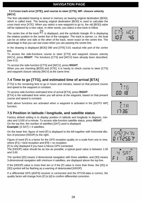
7.3 Cross track error [XTE], and course to steer [CTS], WP. closure velocity[WCV]The first calculated bearing is stored in memory as bearing original destination [BOD],which is called track. The bearing original destination [BOD] is used to calculate thecross track error [XTE]. When you select a new waypoint to go to, the old [BOD] valuewill be replaced by a new value. In other words, you select a new track to follow.
The centre line of the track is displayed, and the symbolic triangle is displayingthe relative position to the centre line of the navigator. The track is narrow; i.e. the boatcan be on either one side or the other of the track, never exact on the centre line. Theadvantage is that you can see exact when you are passing the centre line.
In the drawing is displayed [BOD] 090 and [XTE] 0.01 nautical mile port of the centreline.To access the side-functions course to steer [CTS] and waypoint closure velocity[WCV], press RIGHT. The functions [CTS] and [WCV] have already been described,(see 6.2).
To access the side-function [CTS] and [WCV], press RIGHT.When you are checking [BOD] and [XTE], it is handy to check course to steer [CTS]and waypoint closure velocity [WCV] at the same time.
7.4 Time to go [TTG], and estimated time of arrival [ETA][TTG] is the remaining time to go in hours and minutes, based on that present courseand speed to the waypoint is constant.
To access side-function estimated time of arrival [ETA], press RIGHT.[ETA] is the estimated time when you will arrive at the waypoint, based on that presentcourse and speed is constant.
Both above functions are activated when a waypoint is activated in the [GOTO WP]function.
7.5 Position in latitude / longitude, and satellite statusFactory default setting is to display position in latitude and longitude in degrees, min-utes and 1/100 of a minute. To access side-function satellite status, press RIGHT.On the top line, the number of satellites [SAT] used is displayed.Example: [4 SAT] = 4 satellites.
On the lower line, figure of merit [F] is displayed to the left together with horizontal dilu-tion of precision [HDOP] to the right.
Figure of merit [F] is a factor for the GPS reception quality on a scale from one to nine,where [F1] = best reception and [F9] = no reception.[F] Is only displayed if you have a Nexus GPS connected.The [HDOP] value should be as low as possible, a typical good value is between 1.00and 3.00.
The symbol [2D] means 2-dimensional navigation with three satellites, and [3D] means3-dimensional navigation with minimum 4 satellites, are displayed above the top line.
If the [HDOP] value is more than ten or if the [F] value is more than three, the [2D] or[3D] symbol will be flashing as a warning of deteriorated [HDOP].
If a differential GPS [dGPS] receiver is connected and the RTCM-data is correct, thequality factor will change from [F] to [d] to confirm differential correction.
NAVIGATION PAGE
29
8 WP page (Optional)
Optional page!
Note! The Remote Control instrument is factory default set with the optionalpage closed. The optional page has to be opened individually to gain accessto the page. These pages are considered optional for advanced users only.
To open WP page:Press PAGE RIGHT until text [SETUP] appears, followed by text [ALARMS].Press UP once to display [CONFIG], then press KEY to display text [NEXUS Con-trol].Press UP once to display [USE+ - - - Pages].Each [+] indicates that the corresponding page is open.Each [-] indicated that the corresponding page is closed.[USE++++] means that all main pages BOAT, NAV, WPT and ROUTE are open.
To open WP page, press KEY. The first [+] flashes.Use LEFT or RIGHT to select 3:rd [-] from left, and use UP or DOWN to open [+]the page. To lock your setting, press KEY.
The WP page is used when a Nexus GPS (WP 0-99), a Nexus GPS Navigator (WP 0-399) or a NMEA navigator is connected to the Nexus Server.Under the WP page you can mark, edit, view, copy, move and delete waypoints.The Remote Control instrument can use waypoints that are stored in the active Nexusnavigator. No waypoints are stored in the Remote Control instrument.If you have a NMEA navigator and you want the possibility to navigate with the help ofthe Remote Control instrument, you shall configure your Nexus Server to perform thenavigation.
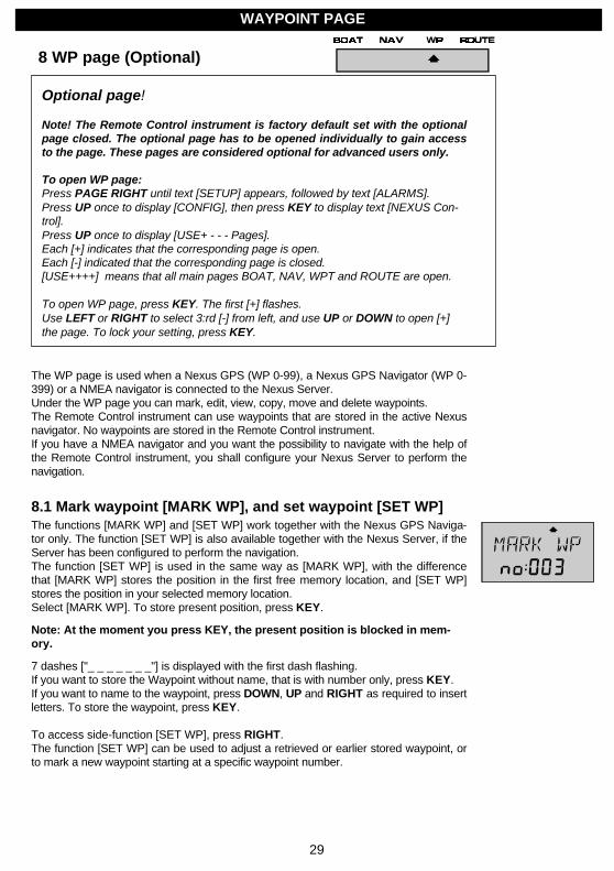
8.1 Mark waypoint [MARK WP], and set waypoint [SET WP]The functions [MARK WP] and [SET WP] work together with the Nexus GPS Naviga-tor only. The function [SET WP] is also available together with the Nexus Server, if theServer has been configured to perform the navigation.The function [SET WP] is used in the same way as [MARK WP], with the differencethat [MARK WP] stores the position in the first free memory location, and [SET WP]stores the position in your selected memory location.Select [MARK WP]. To store present position, press KEY.
Note: At the moment you press KEY, the present position is blocked in mem-ory.
7 dashes ["_ _ _ _ _ _ _"] is displayed with the first dash flashing.If you want to store the Waypoint without name, that is with number only, press KEY.If you want to name to the waypoint, press DOWN, UP and RIGHT as required to insertletters. To store the waypoint, press KEY.
To access side-function [SET WP], press RIGHT.The function [SET WP] can be used to adjust a retrieved or earlier stored waypoint, orto mark a new waypoint starting at a specific waypoint number.
WAYPOINT PAGE
30
Example of a likely scenario:From your sea chart you select a position for a waypoint, and you call it ["N-CAPE "].Enter the waypoint in [EDIT WP], and activate the waypoint in [GOTO WP].You start to navigate towards the position, and when you approach, you realise that theco-ordinates are too far north. You decide to correct the waypoint, and therefore selectto pass the exact position where you want to store the waypoint.Select [SET WP], and press KEY. The first free waypoint number flashes.To store and over-write the corrected waypoint with your new position, first search forthe waypoint number to be corrected, by pressing DOWN, UP and LEFT, RIGHT asrequired.When the waypoint number is found, press KEY at the exact position where you wantto store the waypoint. The ["N"] in ["N-CAPE "] flashes to allow a change of the name.If you want to keep the name, just press KEY.["N-CAPE "] is now corrected to the specific waypoint number you selected.
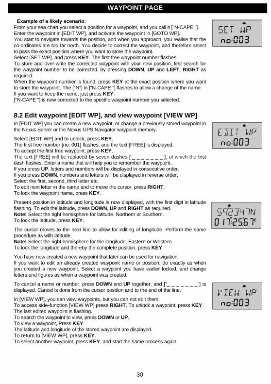
8.2 Edit waypoint [EDIT WP], and view waypoint [VIEW WP]In [EDIT WP] you can create a new waypoint, or change a previously stored waypoint inthe Nexus Server or the Nexus GPS Navigator waypoint memory.
Select [EDIT WP] and to unlock, press KEY.The first free number [no: 001] flashes, and the text [FREE] is displayed.To accept the first free waypoint, press KEY.The text [FREE] will be replaced by seven dashes ["_ _ _ _ _ _ _"], of which the firstdash flashes. Enter a name that will help you to remember the waypoint.If you press UP, letters and numbers will be displayed in consecutive order.If you press DOWN, numbers and letters will be displayed in reverse order.Select the first, second, third letter etc.To edit next letter in the name and to move the cursor, press RIGHT.To lock the waypoint name, press KEY.
Present position in latitude and longitude is now displayed, with the first digit in latitudeflashing. To edit the latitude, press DOWN, UP and RIGHT as required.Note! Select the right hemisphere for latitude, Northern or Southern.To lock the latitude, press KEY.
The cursor moves to the next line to allow for editing of longitude. Perform the sameprocedure as with latitude,Note! Select the right hemisphere for the longitude, Eastern or Western.To lock the longitude and thereby the complete position, press KEY.
You have now created a new waypoint that later can be used for navigation.If you want to edit an already created waypoint name or position, do exactly as whenyou created a new waypoint. Select a waypoint you have earlier locked, and changeletters and figures as when a waypoint was created.
To cancel a name or number, press DOWN and UP together, and ["_ _ _ _ _ _ _"] isdisplayed. Cancel is done from the cursor position and to the end of the line.
In [VIEW WP], you can view waypoints, but you can not edit them.To access side-function [VIEW WP] press RIGHT. To unlock a waypoint, press KEY.The last edited waypoint is flashing.To search the waypoint to view, press DOWN or UP.To view a waypoint, Press KEY.The latitude and longitude of the stored waypoint are displayed.To return to [VIEW WP], press KEY.To select another waypoint, press KEY, and start the same process again.
WAYPOINT PAGE
31
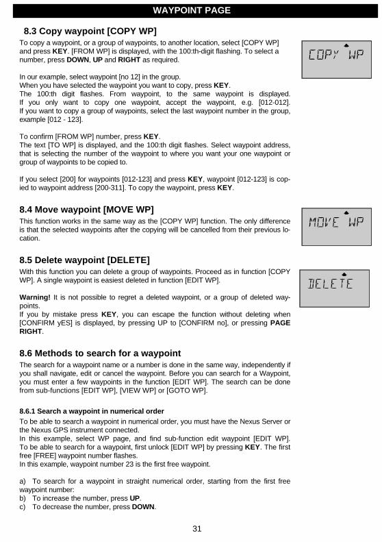
8.3 Copy waypoint [COPY WP]To copy a waypoint, or a group of waypoints, to another location, select [COPY WP]and press KEY. [FROM WP] is displayed, with the 100:th-digit flashing. To select anumber, press DOWN, UP and RIGHT as required.
In our example, select waypoint [no 12] in the group.When you have selected the waypoint you want to copy, press KEY.The 100:th digit flashes. From waypoint, to the same waypoint is displayed.If you only want to copy one waypoint, accept the waypoint, e.g. [012-012].If you want to copy a group of waypoints, select the last waypoint number in the group,example [012 - 123].
To confirm [FROM WP] number, press KEY.The text [TO WP] is displayed, and the 100:th digit flashes. Select waypoint address,that is selecting the number of the waypoint to where you want your one waypoint orgroup of waypoints to be copied to.
If you select [200] for waypoints [012-123] and press KEY, waypoint [012-123] is cop-ied to waypoint address [200-311]. To copy the waypoint, press KEY.
8.4 Move waypoint [MOVE WP]This function works in the same way as the [COPY WP] function. The only differenceis that the selected waypoints after the copying will be cancelled from their previous lo-cation.
8.5 Delete waypoint [DELETE]With this function you can delete a group of waypoints. Proceed as in function [COPYWP]. A single waypoint is easiest deleted in function [EDIT WP].
Warning! It is not possible to regret a deleted waypoint, or a group of deleted way-points.If you by mistake press KEY, you can escape the function without deleting when[CONFIRM yES] is displayed, by pressing UP to [CONFIRM no], or pressing PAGERIGHT.
8.6 Methods to search for a waypointThe search for a waypoint name or a number is done in the same way, independently ifyou shall navigate, edit or cancel the waypoint. Before you can search for a Waypoint,you must enter a few waypoints in the function [EDIT WP]. The search can be donefrom sub-functions [EDIT WP], [VIEW WP] or [GOTO WP].
8.6.1 Search a waypoint in numerical orderTo be able to search a waypoint in numerical order, you must have the Nexus Server orthe Nexus GPS instrument connected.In this example, select WP page, and find sub-function edit waypoint [EDIT WP].To be able to search for a waypoint, first unlock [EDIT WP] by pressing KEY. The firstfree [FREE] waypoint number flashes.In this example, waypoint number 23 is the first free waypoint.
a) To search for a waypoint in straight numerical order, starting from the first freewaypoint number:b) To increase the number, press UP.c) To decrease the number, press DOWN.
WAYPOINT PAGE
32
d) To search for a specific waypoint number, starting from the first free waypointnumber:Based on the 1:st digit, press LEFT once.Based on the 10:th digit, press LEFT twice.Based on the 100:th digit, press LEFT 3 times.
When you have pressed LEFT the digit flashes and is ready for search UP or DOWN.When you have found your searched waypoint, press KEY to edit it.First the name flashes. Edit and / or press KEY to continue.Then the latitude flashes. Edit and / or press KEY to continue.Finally the longitude flashes. Edit and / or press KEY, to lock it.In the same way as described above, you can search for a route name in numerical or-der under the ROUTE page.
8.6.2 Search for a waypoint in alphabetical orderTo be able to name a waypoint and then search for it in alphabetical order, you musthave a Nexus GPS Navigator connected.In this example, select NAV page and sub-function [GOTO WP]. To be able to searchfor a waypoint, first unlock the [GOTO WP] function by pressing KEY. The last editedwaypoint is displayed with flashing number.
a) To search for a waypoint name in straight alphabetical order, starting from the lastedited waypoint, press RIGHT and the waypoint name flashes:- To forward the alphabetical order, press UP.- To reverse alphabetical order, press DOWN,
b) To search for a waypoint name, letter by letter, starting from the first letter in the
last edited Waypoint:- Based on the first letter, press LEFT once.- Based on the second letter, press LEFT twice.- Based on the third letter, press LEFT three times, etc. up to the seven lettersavailable.
When you have pressed LEFT, the corresponding letter flashes, and is ready forsearch UP or DOWN.When you press UP, the next waypoint name found in the memory with this letter or thenext available letter in alphabetical order is displayed.When you press DOWN, the next waypoint name found in the memory with this letter orpreceding letter in alphabetical order is displayed.When you have found your searched waypoint, to select it press KEY.The waypoint name and number will be displayed as a confirmation.
If no waypoint with the selected letter resides in the memory, the letter flashes continu-ously and the waypoint is left in the display.
In the same way as described above you can search for a route name in alphabeticalunder ROUTE page.
WAYPOINT PAGE
33
9 ROUTE page (Optional)
Optional page!
Note! The Remote Control instrument is factory default set with the optionalpage closed. The optional page has to be opened individually to gain accessto the page. These pages are considered optional for advanced users only.
To open ROUTE page:Press PAGE RIGHT until text [SETUP] appears, followed by text [ALARMS].Press UP once to display [CONFIG], then press KEY to display text [NEXUS Con-trol].Press UP once to display [USE+ - - - Pages].Each [+] indicates that the corresponding page is open.Each [-] indicated that the corresponding page is closed.[USE++++] means that all main pages BOAT, NAV, WPT and ROUTE are open.
To open ROUTE page, press KEY. The first [+] flashes.Use LEFT or RIGHT to select 4:th [-] from left, and use UP or DOWN to open [+]the page. To lock your setting, press KEY.
The page is used when a Nexus GPS Antenna / portable GPS (WP 0-99), a NexusGPS Navigator (WP 0-399) or a NMEA navigator is connected to the Nexus Server.To use all functions under the ROUTE page, the Nexus GPS Navigator must be con-nected and set in [MASTER] mode, and some waypoints must have been entered un-der the WP page.
With a route we mean a sequence of waypoints combined together in a sailplan thatmakes up your planned travel itinerary, which is stored as a route.
When the route is activated and you arrive at each waypoint, an arrival alarm will soundand the next waypoint in the route list will be activated automatically.
The ROUTE page can store up to 24 routes, with up to 24 waypoints in each route.We recommend using Waypoints 0-50 for temporary waypoints, and the remainingwaypoints for the sailplans.
If you edit a waypoint that belongs to a route, the route will be affected.
9.1 Sailplan [SAIL PLAn]When a route is created or activated, that is used for navigation, it is called a [SAILPLAn].In the [SAIL PLAn] you can create or edit one sailplan with up to 24 waypoints.If you have a Nexus GPS Navigator connected you can later store the whole sailplanwith the function route store [ROUTE StorE].If you have a Nexus Server as navigator you can use the sailplan, but not store it.A sailplan is consumed successively as the waypoints are passed. The last waypoint isnot cancelled automatically; it must be cancelled manually.
To cancel the last waypoint, select [GOTO WP], and press DOWN and UP together.Waypoint (000) is always defined as the present position.To input the first leg in the [SAIL PLAn], Select [SAIL PLAn], and press KEY.If no [GOTO WP] is defined, waypoint (000) is displayed.If a [GOTO WP] is defined, that waypoint number is automatically entered into the sail-plan and displayed.
ROUTE PAGE
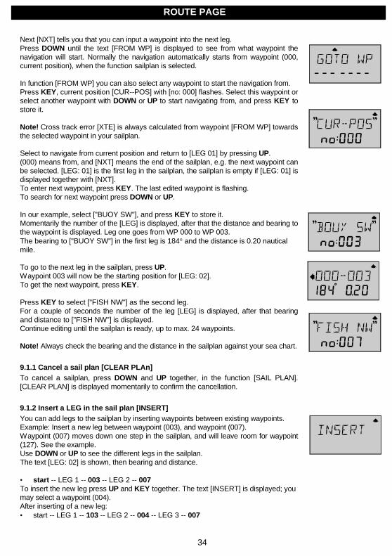
34
Next [NXT] tells you that you can input a waypoint into the next leg.Press DOWN until the text [FROM WP] is displayed to see from what waypoint thenavigation will start. Normally the navigation automatically starts from waypoint (000,current position), when the function sailplan is selected.
In function [FROM WP] you can also select any waypoint to start the navigation from.Press KEY, current position [CUR--POS] with [no: 000] flashes. Select this waypoint orselect another waypoint with DOWN or UP to start navigating from, and press KEY tostore it.
Note! Cross track error [XTE] is always calculated from waypoint [FROM WP] towardsthe selected waypoint in your sailplan.
Select to navigate from current position and return to [LEG 01] by pressing UP.(000) means from, and [NXT] means the end of the sailplan, e.g. the next waypoint canbe selected. [LEG: 01] is the first leg in the sailplan, the sailplan is empty if [LEG: 01] isdisplayed together with [NXT].To enter next waypoint, press KEY. The last edited waypoint is flashing.To search for next waypoint press DOWN or UP.
In our example, select ["BUOY SW"], and press KEY to store it.Momentarily the number of the [LEG] is displayed, after that the distance and bearing tothe waypoint is displayed. Leg one goes from WP 000 to WP 003.The bearing to ["BUOY SW"] in the first leg is 184° and the distance is 0.20 nauticalmile.
To go to the next leg in the sailplan, press UP.Waypoint 003 will now be the starting position for [LEG: 02].To get the next waypoint, press KEY.
Press KEY to select ["FISH NW"] as the second leg.For a couple of seconds the number of the leg [LEG] is displayed, after that bearingand distance to ["FISH NW"] is displayed.Continue editing until the sailplan is ready, up to max. 24 waypoints.
Note! Always check the bearing and the distance in the sailplan against your sea chart.
9.1.1 Cancel a sail plan [CLEAR PLAn]To cancel a sailplan, press DOWN and UP together, in the function [SAIL PLAN].[CLEAR PLAN] is displayed momentarily to confirm the cancellation.
9.1.2 Insert a LEG in the sail plan [INSERT]You can add legs to the sailplan by inserting waypoints between existing waypoints.Example: Insert a new leg between waypoint (003), and waypoint (007).Waypoint (007) moves down one step in the sailplan, and will leave room for waypoint(127). See the example.Use DOWN or UP to see the different legs in the sailplan.The text [LEG: 02] is shown, then bearing and distance.
• start -- LEG 1 -- 003 -- LEG 2 -- 007To insert the new leg press UP and KEY together. The text [INSERT] is displayed; youmay select a waypoint (004).After inserting of a new leg:• start -- LEG 1 -- 103 -- LEG 2 -- 004 -- LEG 3 -- 007
ROUTE PAGE

35
9.1.3 Cancel a LEG in the sail planTo cancel waypoint (004) in (LEG 2) without affecting the sailplan in any other way.Use DOWN or UP to search (LEG 2).First (LEG 2) is displayed, then bearing and distance.To remove waypoint (004) in (LEG 2), press DOWN and UP together.Before:• start -- LEG 1 -- 103 -- LEG 2 -- 004 -- LEG 3 – 007After:• start -- LEG 1 -- 103 -- LEG 2 – 007
9.2 Store a route [ROUTE StorE]The function [ROUTE StorE] is used to store the route you have created in [SAILPLAn].Select [ROUTE StorE], and press KEY to unlock it.The first free route number [no: 001] is flashing, press KEY to unlock it.The first position for a letter is flashing, give the route a name with DOWN, UP andRIGHT.Press KEY, and the number of stored waypoints is displayed momentarily.
9.3 Route call [ROUTE CALL]To use [ROUTE CALL] at least one route must first be stored. [ROUTE CALL] willcopy and activate a selected route to the sailplan.
To unlock [ROUTE CALL], press KEY, and last active route will be displayed with theroute number flashing.To select a route, press DOWN or UP. To activate it, press KEY.The route has now been copied to the [SAIL PLAn].The leg name is displayed momentarily and then bearing and distance to first the way-point is displayed.
It is possible to add more than one route to the sailplan which, as long as the totalnumber of waypoints in the sailplan is less than 25.
9.4 Reverse route call [REVERSE CALL]To use [REVERSE CALL] at least one route must first be stored. [REVERSE CALL]will copy a selected route in reverse order to the sailplan, and activate it.[REVERSE CALL] is used in the same way as [ROUTE CALL].
Press KEY. Route number (001) flashes, select a route with DOWN or UP, and pressKEY to store activate it in the sailplan.The route has now been copied in reverse order; i.e. the last waypoint in the route isnow the first in the sailplan.
9.5 Delete a route [DELETE][DELETE] deletes a selected route from the memory.Press KEY and the first route number (001) flashes.To select a route press DOWN or UP.To cancel the route, press DOWN and UP together.A long tone will be heard and the text [DELETE] will be displayed momentarily.
Warning! A deleted route can not be regretted once it is executed.
ROUTE PAGE
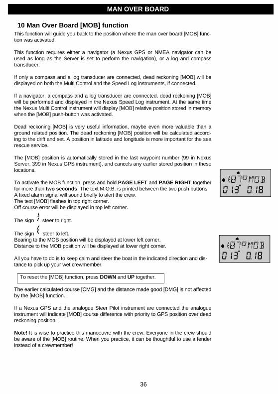
36
10 Man Over Board [MOB] functionThis function will guide you back to the position where the man over board [MOB] func-tion was activated.
This function requires either a navigator (a Nexus GPS or NMEA navigator can beused as long as the Server is set to perform the navigation), or a log and compasstransducer.
If only a compass and a log transducer are connected, dead reckoning [MOB] will bedisplayed on both the Multi Control and the Speed Log instruments, if connected.
If a navigator, a compass and a log transducer are connected, dead reckoning [MOB]will be performed and displayed in the Nexus Speed Log instrument. At the same timethe Nexus Multi Control instrument will display [MOB] relative position stored in memorywhen the [MOB] push-button was activated.
Dead reckoning [MOB] is very useful information, maybe even more valuable than aground related position. The dead reckoning [MOB] position will be calculated accord-ing to the drift and set. A position in latitude and longitude is more important for the searescue service.
The [MOB] position is automatically stored in the last waypoint number (99 in NexusServer, 399 in Nexus GPS instrument), and cancels any earlier stored position in theselocations.
To activate the MOB function, press and hold PAGE LEFT and PAGE RIGHT togetherfor more than two seconds. The text M.O.B. is printed between the two push buttons.A fixed alarm signal will sound briefly to alert the crew.The text [MOB] flashes in top right corner.Off course error will be displayed in top left corner.
The sign steer to right.
The sign steer to left.Bearing to the MOB position will be displayed at lower left corner.Distance to the MOB position will be displayed at lower right corner.
All you have to do is to keep calm and steer the boat in the indicated direction and dis-tance to pick up your wet crewmember.
To reset the [MOB] function, press DOWN and UP together.
The earlier calculated course [CMG] and the distance made good [DMG] is not affectedby the [MOB] function.
If a Nexus GPS and the analogue Steer Pilot instrument are connected the analogueinstrument will indicate [MOB] course difference with priority to GPS position over deadreckoning position.
Note! It is wise to practice this manoeuvre with the crew. Everyone in the crew shouldbe aware of the [MOB] routine. When you practice, it can be thoughtful to use a fenderinstead of a crewmember!
MAN OVER BOARD
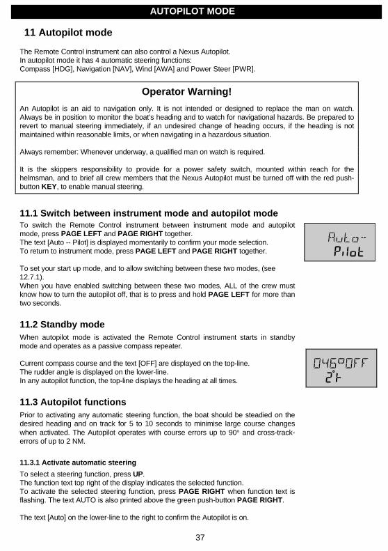
37
11 Autopilot mode
The Remote Control instrument can also control a Nexus Autopilot.In autopilot mode it has 4 automatic steering functions:Compass [HDG], Navigation [NAV], Wind [AWA] and Power Steer [PWR].
Operator Warning!
An Autopilot is an aid to navigation only. It is not intended or designed to replace the man on watch.Always be in position to monitor the boat’s heading and to watch for navigational hazards. Be prepared torevert to manual steering immediately, if an undesired change of heading occurs, if the heading is notmaintained within reasonable limits, or when navigating in a hazardous situation.
Always remember: Whenever underway, a qualified man on watch is required.
It is the skippers responsibility to provide for a power safety switch, mounted within reach for thehelmsman, and to brief all crew members that the Nexus Autopilot must be turned off with the red push-button KEY, to enable manual steering.
11.1 Switch between instrument mode and autopilot modeTo switch the Remote Control instrument between instrument mode and autopilotmode, press PAGE LEFT and PAGE RIGHT together.The text [Auto -- Pilot] is displayed momentarily to confirm your mode selection.To return to instrument mode, press PAGE LEFT and PAGE RIGHT together.
To set your start up mode, and to allow switching between these two modes, (see12.7.1).When you have enabled switching between these two modes, ALL of the crew mustknow how to turn the autopilot off, that is to press and hold PAGE LEFT for more thantwo seconds.
11.2 Standby modeWhen autopilot mode is activated the Remote Control instrument starts in standbymode and operates as a passive compass repeater.
Current compass course and the text [OFF] are displayed on the top-line.The rudder angle is displayed on the lower-line.In any autopilot function, the top-line displays the heading at all times.
11.3 Autopilot functionsPrior to activating any automatic steering function, the boat should be steadied on thedesired heading and on track for 5 to 10 seconds to minimise large course changeswhen activated. The Autopilot operates with course errors up to 90° and cross-track-errors of up to 2 NM.
11.3.1 Activate automatic steering
To select a steering function, press UP.The function text top right of the display indicates the selected function.To activate the selected steering function, press PAGE RIGHT when function text isflashing. The text AUTO is also printed above the green push-button PAGE RIGHT.
The text [Auto] on the lower-line to the right to confirm the Autopilot is on.
AUTOPILOT MODE
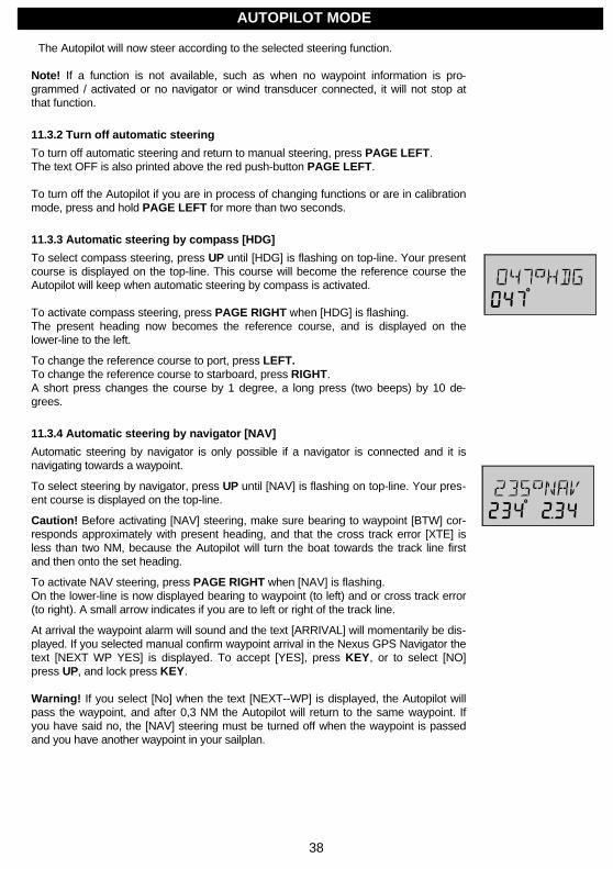
38
The Autopilot will now steer according to the selected steering function.
Note! If a function is not available, such as when no waypoint information is pro-grammed / activated or no navigator or wind transducer connected, it will not stop atthat function.
11.3.2 Turn off automatic steering
To turn off automatic steering and return to manual steering, press PAGE LEFT.The text OFF is also printed above the red push-button PAGE LEFT.
To turn off the Autopilot if you are in process of changing functions or are in calibrationmode, press and hold PAGE LEFT for more than two seconds.
11.3.3 Automatic steering by compass [HDG]
To select compass steering, press UP until [HDG] is flashing on top-line. Your presentcourse is displayed on the top-line. This course will become the reference course theAutopilot will keep when automatic steering by compass is activated.
To activate compass steering, press PAGE RIGHT when [HDG] is flashing.The present heading now becomes the reference course, and is displayed on thelower-line to the left.
To change the reference course to port, press LEFT.To change the reference course to starboard, press RIGHT.A short press changes the course by 1 degree, a long press (two beeps) by 10 de-grees.
11.3.4 Automatic steering by navigator [NAV]
Automatic steering by navigator is only possible if a navigator is connected and it isnavigating towards a waypoint.
To select steering by navigator, press UP until [NAV] is flashing on top-line. Your pres-ent course is displayed on the top-line.
Caution! Before activating [NAV] steering, make sure bearing to waypoint [BTW] cor-responds approximately with present heading, and that the cross track error [XTE] isless than two NM, because the Autopilot will turn the boat towards the track line firstand then onto the set heading.
To activate NAV steering, press PAGE RIGHT when [NAV] is flashing.On the lower-line is now displayed bearing to waypoint (to left) and or cross track error(to right). A small arrow indicates if you are to left or right of the track line.
At arrival the waypoint alarm will sound and the text [ARRIVAL] will momentarily be dis-played. If you selected manual confirm waypoint arrival in the Nexus GPS Navigator thetext [NEXT WP YES] is displayed. To accept [YES], press KEY, or to select [NO]press UP, and lock press KEY.
Warning! If you select [No] when the text [NEXT--WP] is displayed, the Autopilot willpass the waypoint, and after 0,3 NM the Autopilot will return to the same waypoint. Ifyou have said no, the [NAV] steering must be turned off when the waypoint is passedand you have another waypoint in your sailplan.
AUTOPILOT MODE
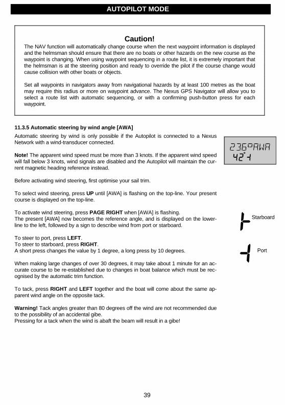
39
Caution!The NAV function will automatically change course when the next waypoint information is displayedand the helmsman should ensure that there are no boats or other hazards on the new course as thewaypoint is changing. When using waypoint sequencing in a route list, it is extremely important thatthe helmsman is at the steering position and ready to override the pilot if the course change wouldcause collision with other boats or objects.
Set all waypoints in navigators away from navigational hazards by at least 100 metres as the boatmay require this radius or more on waypoint advance. The Nexus GPS Navigator will allow you toselect a route list with automatic sequencing, or with a confirming push-button press for eachwaypoint.
11.3.5 Automatic steering by wind angle [AWA]
Automatic steering by wind is only possible if the Autopilot is connected to a NexusNetwork with a wind-transducer connected.
Note! The apparent wind speed must be more than 3 knots. If the apparent wind speedwill fall below 3 knots, wind signals are disabled and the Autopilot will maintain the cur-rent magnetic heading reference instead.
Before activating wind steering, first optimise your sail trim.
To select wind steering, press UP until [AWA] is flashing on the top-line. Your presentcourse is displayed on the top-line.
To activate wind steering, press PAGE RIGHT when [AWA] is flashing.The present [AWA] now becomes the reference angle, and is displayed on the lower-line to the left, followed by a sign to describe wind from port or starboard.
To steer to port, press LEFT.To steer to starboard, press RIGHT.A short press changes the value by 1 degree, a long press by 10 degrees.
When making large changes of over 30 degrees, it may take about 1 minute for an ac-curate course to be re-established due to changes in boat balance which must be rec-ognised by the automatic trim function.
To tack, press RIGHT and LEFT together and the boat will come about the same ap-parent wind angle on the opposite tack.
Warning! Tack angles greater than 80 degrees off the wind are not recommended dueto the possibility of an accidental gibe.Pressing for a tack when the wind is abaft the beam will result in a gibe!
Starboard
Port
AUTOPILOT MODE

40
11.3.6 Power steering [PWR]
To select power steering, press UP until [PWR] is flashing on the top-line. Your presentcourse is displayed on the top-line.
To activate power steering, press PAGE RIGHT when [PWR] is flashing.The rudder angle followed by a sign for port or starboard is displayed on the lower-line.
To change the rudder angle to starboard press RIGHT and hold it, until the desiredrudder angle is displayed.
To change the rudder angle to port press LEFT and hold it, until the desired rudder an-gle is displayed.
11.3.7 Dodging and returning to last steering function
To dodge, turn off the automatic steering by pressing PAGE LEFT, and dodge manu-ally.
If you want to re-activate the last steering function and value, press DOWN and UP to-gether, within 10 minutes after turning off the automatic steering.
This function is not available after 10 minutes after Autopilot off, or if the Autopilot hasbeen turned off by pressing PAGE LEFT for more than two seconds.
AUTOPILOT MODE
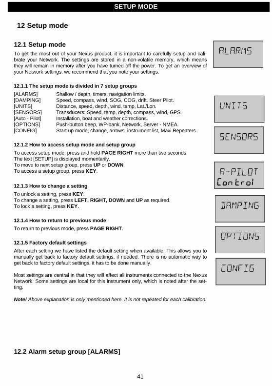
41
12 Setup mode
12.1 Setup modeTo get the most out of your Nexus product, it is important to carefully setup and cali-brate your Network. The settings are stored in a non-volatile memory, which meansthey will remain in memory after you have turned off the power. To get an overview ofyour Network settings, we recommend that you note your settings.
12.1.1 The setup mode is divided in 7 setup groups
[ALARMS] Shallow / depth, timers, navigation limits.[DAMPING] Speed, compass, wind, SOG, COG, drift. Steer Pilot.[UNITS] Distance, speed, depth, wind, temp, Lat./Lon.[SENSORS] Transducers: Speed, temp, depth, compass, wind, GPS.[Auto - Pilot] Installation, boat and weather corrections.[OPTIONS] Push-button beep, WP-bank, Network, Server - NMEA.[CONFIG] Start up mode, change, arrows, instrument list, Maxi Repeaters.
12.1.2 How to access setup mode and setup group
To access setup mode, press and hold PAGE RIGHT more than two seconds.The text [SETUP] is displayed momentarily.To move to next setup group, press UP or DOWN.To access a setup group, press KEY.
12.1.3 How to change a setting
To unlock a setting, press KEY.To change a setting, press LEFT, RIGHT, DOWN and UP as required.To lock a setting, press KEY.
12.1.4 How to return to previous mode
To return to previous mode, press PAGE RIGHT.
12.1.5 Factory default settings
After each setting we have listed the default setting when available. This allows you tomanually get back to factory default settings, if needed. There is no automatic way toget back to factory default settings, it has to be done manually.
Most settings are central in that they will affect all instruments connected to the NexusNetwork. Some settings are local for this instrument only, which is noted after the set-ting.
Note! Above explanation is only mentioned here. It is not repeated for each calibration.
12.2 Alarm setup group [ALARMS]
SETUP MODE
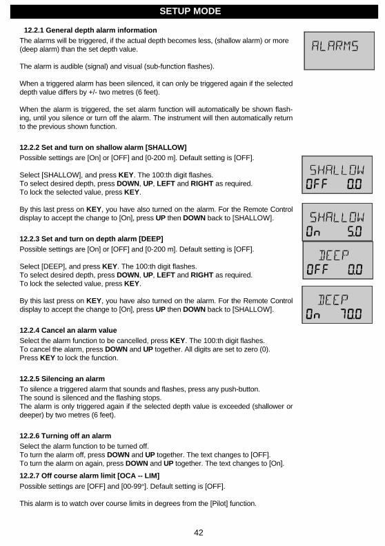
42
12.2.1 General depth alarm informationThe alarms will be triggered, if the actual depth becomes less, (shallow alarm) or more(deep alarm) than the set depth value.
The alarm is audible (signal) and visual (sub-function flashes).
When a triggered alarm has been silenced, it can only be triggered again if the selecteddepth value differs by +/- two metres (6 feet).
When the alarm is triggered, the set alarm function will automatically be shown flash-ing, until you silence or turn off the alarm. The instrument will then automatically returnto the previous shown function.
12.2.2 Set and turn on shallow alarm [SHALLOW]Possible settings are [On] or [OFF] and [0-200 m]. Default setting is [OFF].
Select [SHALLOW], and press KEY. The 100:th digit flashes.To select desired depth, press DOWN, UP, LEFT and RIGHT as required.To lock the selected value, press KEY.
By this last press on KEY, you have also turned on the alarm. For the Remote Controldisplay to accept the change to [On], press UP then DOWN back to [SHALLOW].
12.2.3 Set and turn on depth alarm [DEEP]Possible settings are [On] or [OFF] and [0-200 m]. Default setting is [OFF].
Select [DEEP], and press KEY. The 100:th digit flashes.To select desired depth, press DOWN, UP, LEFT and RIGHT as required.To lock the selected value, press KEY.
By this last press on KEY, you have also turned on the alarm. For the Remote Controldisplay to accept the change to [On], press UP then DOWN back to [SHALLOW].
12.2.4 Cancel an alarm valueSelect the alarm function to be cancelled, press KEY. The 100:th digit flashes.To cancel the alarm, press DOWN and UP together. All digits are set to zero (0).Press KEY to lock the function.
12.2.5 Silencing an alarmTo silence a triggered alarm that sounds and flashes, press any push-button.The sound is silenced and the flashing stops.The alarm is only triggered again if the selected depth value is exceeded (shallower ordeeper) by two metres (6 feet).
12.2.6 Turning off an alarmSelect the alarm function to be turned off.To turn the alarm off, press DOWN and UP together. The text changes to [OFF].To turn the alarm on again, press DOWN and UP together. The text changes to [On].
12.2.7 Off course alarm limit [OCA -- LIM]Possible settings are [OFF] and [00-99°]. Default setting is [OFF].
This alarm is to watch over course limits in degrees from the [Pilot] function.
SETUP MODE
43
Set maximum average course limit in degrees (damping 30 sec.) to be allowed beforethe alarm will be triggered.
If set, this alarm is automatically activated when a steer reference is selected in thesub-function [Pilot].
12.2.8 Pilot off course alarm [PCA]Possible settings are [OFF] and [00-99°]. Default setting is [OFF].
This alarm is to watch over an activated Nexus Autopilot, which must be connected tobe able to activate the function.Set maximum average course limit in degrees (damping 30s) to be allowed before thealarm will be triggered.
12.2.9 Watch-out timer alarm [W-TIMER]Possible settings are [On] or [OFF]. Default setting is [OFF].The audible alarm will sound every 5 minutes to alert the person on watch.To confirm and restart the timer, press any push-button. If not confirmed within 30seconds the optional buzzer, if connected to the Server, will sound to alert the rest ofthe crew. The alarm sounds for a maximum of 30 seconds.
12.2.10 The 8 named timer alarms [TIMERS]The function [TIMERS] can be set for 8 different alarms. E.g. the most importantweather reports. To use the function you must first set the clock.Setting of the clock can be done in 3 different ways:
1 Manual setting of time and date, in the BOAT page.2 Automatic setting of time and date, from a Nexus GPS.3 Automatic setting of time, from a connected NMEA 0183 GPS Navigator.
For the best accuracy, synchronise the time functions with GPS time.It is possible to use the clock and [TIMERS] without GPS. The accuracy of the clockwithout GPS is a couple of seconds per 24 hours.
To access [TIMER 1], select [TIMERS] and press KEY.To unlock [TIMER 1], press KEY. The sign flashes.The name [TIMER 1] can be changed to ["WEATHER"].To set the name, press DOWN, UP and RIGHT as required. To lock the name, pressKEY.The first digit for the time flashes. The time is settable between 00:00-23:59.To set the time, press DOWN, UP and RIGHT as required.
The on [ON] indication in the lower right corner displays that the alarm is activated.To change between [OFF] and [On], without changing the set time, press DOWN andUP together.The alarm sounds in both the Server and the Remote Control instrument for 30 sec-onds or until confirmed.To access [TIMER 2], [TIMER 3] and so on, until [TIMER 8], press DOWN.To return to the function [TIMER], press PAGE RIGHT.
12.2.11 Navigation arrival alarm [NAV-ALM]
SETUP MODE

44
12.2.11.1 Waypoint circle arrival alarm [CIRCLE]Possible settings are [0.00-9.99]. Default setting is [0.00]. Off = [0.00].
Set the radius of the circle surrounding the waypoint. If you set [CIRCLE] to 0.05 NM,the alarm will sound when the distance to the waypoint is less than 0,05 NM. The alarmwill beep a few times and the text [ARRIVAL] will flash momentarily.
12.2.11.2 Waypoint line arrival alarm [LINE]Possible settings are [On] or [OFF]. Default setting is [OFF].
Only works together with the Nexus GPS Navigator instrument.If set to [On] the arrival alarm will sound when the waypoint is passed in bearing 90from original or desired track. See drawing about [XTE] and [BOD] inside cover ofmanual.
The function is used as a complement to [CIRCLE] alarm because you can not alwayspass close enough so that the circle arrival alarm [CIRCLE] criteria will be met. Mostoften you want next waypoint in the sailplan to be automatically selected with the help ofthe arrival alarm line or circle.
12.2.11.3 Waypoint confirm arrival alarm [NEXT WP]Possible settings are [On] or [OFF]. Default setting is [OFF].
If [NEXT WP] is [On], next waypoint in the sailplan will automatically be activated.If [NEXT WP] is [OFF], a confirmation must be made by pressing KEY before the nextWaypoint is activated.The function [OFF] is of importance when the Autopilot is connected, and you for secu-rity reasons want to prevent an automatic heading change.
12.2.11.4 Cross track error limit alarm [XTE-LIM]Possible settings are [0.00-9.99]. Default setting is [0.00]. Off = [0.00].When the [XTE] value is the same as the set value, the alarm will sound.Can be utilised when tacking to recognise the distance to the centre line.
12.3 Damping setup group [DAMPING]Factory default setting of all dampings are set for use in calm sea. If the sea is rough,you may want to "stabilise" the readout on the display, then select a higher value.Damping controls the response time of the display readout.
Damping time corresponds to the following:d0 No damping d5 40 secd1 2 sec d6 1 min 20 secd2 4 sec d7 2 min 40 secd3 10 sec d8 5 mind4 20 sec d9 10 min
To unlock damping value, press KEYTo change damping value press DOWN or UP as required.To lock the selected value, press KEY.
Local damping only affects the Remote Control instrument.Central damping affects [ALL] instruments connected to the Nexus Network.
SETUP MODE

45
Damping of boat speed through the water [SPEED]Local damping affects only the readings on Remote Control instrument.
12.3.1 Damping of compass heading [COMPASS]Local damping affects only the readings on Remote Control instrument.
12.3.2 Damping of wind angle and wind speed [WIND]Local damping affects only the readings on Remote Control instrument.
12.3.3 Damping of speed and course over ground [SOG/COG]Central damping [ALL] = The setting affects the readings on all connected to Nexus in-struments that can display [SOG/COG].Use a high damping value at low speed, and low damping value at high speed.If differential [dGPS] is used, you can select low damping value even at low speed.
12.3.4 Damping of drift [DRIFT]Central damping [ALL] = The setting affects the readings on all connected Nexus in-struments that can display [DRIFT].
12.3.5 Damping of Steer Pilot instrument [STEER Pilot]Possible settings are [LOW] 1 sec, [MID] 5 sec and [MAX] 22 sec.Default setting is [MID].When this setting is activated by the KEY press a command is send to all analogueSteer Pilot instruments. Every time you enter this setting the [MID] setting will be dis-played, even though you earlier made another selection.
12.4 Unit setup group [UNITS]All unit settings are local and affect only this instrument.
12.4.1 Unit for distance [DIST]Nautical miles [NM]. Kilometres [KM]. Miles [MI]. Default setting is [NM].
12.4.2 Unit for speed [SPD]Knots [KTS]. Miles/h [MPH]. Kilometre/h [KMH]. Default setting is [KTS].
12.4.3 Unit for depth [DEP]Metre [M]. Fathoms [FA]. Feet [F]. Default setting is [M].
12.4.4 Unit for wind speed [WSP]Metres/second [M/S]. Beaufort [F]. Knots [KTS]. Default setting is [M/S].
SETUP MODE

46
12.4.5 Unit for water temperature [TEMP]Celsius [°C]. Fahrenheit [°F]. Default setting is [°C].
12.4.6 Unit for latitude / longitude [SECONDS]Format of position in latitude and longitude. Default setting is [OFF].[SECONDS OFF] = degrees, minutes and 1/100 of a minute.This setting is indicated with a decimal sign [,] after minutes in longitude.[SECONDS ON] = degrees, minutes and seconds.This setting is indicated with no decimal sign after minutes in longitude.
12.5 Transducer setup group [SENSORS]
Setup and calibration of transducers connected to the Nexus Server.
12.5.1 Boat speed calibration [BSP CAL]Possible settings are [1.00-1.99]. Default setting is [1.30].
Calibration value for boat speed and distance.Drive the boat a measured distance at normal speed.Compare the distance with the trip counter.
Calculate the coefficient by following formula:True distance from the sea chart: TTrip counter distance: LThe current calibration value: CNew calibration value: N
If you suspect a current in the water, drive the boat in both directions and divide tripcounter distance by two.
12.5.2 Water temperature offset [W--TEMP]Possible settings are [+/- 0-9°]. Default setting is [0°].[ _ ] = Add value, e.g.[ _1°C]. [ - ] = Subtract value, e.g. [ -1°C].
12.5.3 Depth transducer location [DEP]Possible settings are [+/-0.00-99.9]. Default setting is [00.4].Select if displayed water depth is measured from above (the water level) or below (thekeel).[ - ] = Subtract value. Measure from the keel. Example: [ - 01.2 ADJ][ _ ] = Add value. Measure from the water surface. Example: [ _ 00.4 ADJ]The selected value will be subtracted or added from the measured depth.
12.5.4 conpass transducer calibration CompassAuto-deviation, auto-deviation-check and auto-deviation-clear are only available, if aNexus compass transducer is connected. The auto-deviation routine will automaticallycorrect all possible faults, except alignment.
Note! As soon as you place any kind of ferrous items close to the compass, the auto-deviation and auto-deviation-check routines should be repeated. So if you have packedyour boat for the vacation, think about where you place ferrous items in relation to thecompass transducer.
SETUP MODE
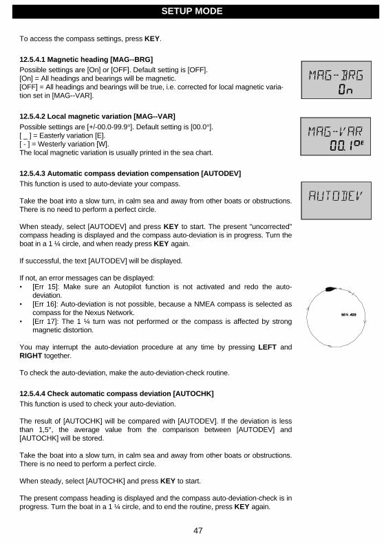
47
To access the compass settings, press KEY.
12.5.4.1 Magnetic heading [MAG--BRG]Possible settings are [On] or [OFF]. Default setting is [OFF].[On] = All headings and bearings will be magnetic.[OFF] = All headings and bearings will be true, i.e. corrected for local magnetic varia-tion set in [MAG--VAR].
12.5.4.2 Local magnetic variation [MAG--VAR]Possible settings are [+/-00.0-99.9°]. Default setting is [00.0°].[ _ ] = Easterly variation [E].[ - ] = Westerly variation [W].The local magnetic variation is usually printed in the sea chart.
12.5.4.3 Automatic compass deviation compensation [AUTODEV]This function is used to auto-deviate your compass.
Take the boat into a slow turn, in calm sea and away from other boats or obstructions.There is no need to perform a perfect circle.
When steady, select [AUTODEV] and press KEY to start. The present "uncorrected"compass heading is displayed and the compass auto-deviation is in progress. Turn theboat in a 1 ¼ circle, and when ready press KEY again.
If successful, the text [AUTODEV] will be displayed.
If not, an error messages can be displayed:• [Err 15]: Make sure an Autopilot function is not activated and redo the auto-
deviation.• [Err 16]: Auto-deviation is not possible, because a NMEA compass is selected as
compass for the Nexus Network.• [Err 17]: The 1 ¼ turn was not performed or the compass is affected by strong
magnetic distortion.
You may interrupt the auto-deviation procedure at any time by pressing LEFT andRIGHT together.
To check the auto-deviation, make the auto-deviation-check routine.
12.5.4.4 Check automatic compass deviation [AUTOCHK]This function is used to check your auto-deviation.
The result of [AUTOCHK] will be compared with [AUTODEV]. If the deviation is lessthan 1,5°, the average value from the comparison between [AUTODEV] and[AUTOCHK] will be stored.
Take the boat into a slow turn, in calm sea and away from other boats or obstructions.There is no need to perform a perfect circle.
When steady, select [AUTOCHK] and press KEY to start.
The present compass heading is displayed and the compass auto-deviation-check is inprogress. Turn the boat in a 1 ¼ circle, and to end the routine, press KEY again.
SETUP MODE
48
If successful, the text [AUTOCHK] will be displayed.
If not, [ERR 17] or [ERR 19] will appear, i.e. the difference between the last auto-deviation and this auto-deviation-check was too big to be accepted.
Make a new auto-deviation-check, and if you still get [ERR 19], make a new auto-deviation, since the last one was probably disturbed.
12.5.4.5 Clear automatic compass deviation [AUTOCLR]This function clears the calibration created by the auto-deviation.You must confirm [CONFIRM] with [yES] or [no].[YES] will cancel. [No] will interrupt without clearing.
12.5.4.6 Adjust compass transducer alignment [ADJUST]Possible settings are [000-359]. Default setting is [0.00].
Compass transducer alignment correction or the so-called "A-fault".Allows 180° reversed mounting if needed. Never mount the transducer in a 90° positionrelative to the boats fore-aft line.
Make sure that the local magnetic variation is entered before you make the alignmentadjustment, otherwise you are unable to see the difference between local magneticvariation and alignment error.
To check the transducer position, sail/drive your boat in a straight line towards two visi-ble objects in a line. If the actual heading taken from the sea chart is 330° and thecompass displays 335°, then set value to 360° - 5° = 355°.
12.5.5 Wind transducer calibration [WIND]To access the wind settings, press KEY.
12.5.5.1 True or relative wind angle in Multi Control instrument [USE TWA]Possible settings are [On] or [OFF]. Default setting is [OFF].
[USE TWA] is the same function as Nexus Multi Control instrument calibration [C51OFF TWA]. Selects true or apparent wind angle in Nexus Multi Control instrument,main-function Wind and in the analogue Wind Angle instrument.[OFF] = Relative wind angle. [On] = True wind angle.
12.5.5.2 Wind speed [W--SPEED]Default setting of wind speed value is [1.50]. Do not change!
12.5.5.3 Wind transducer alignment [W--ANGLE]Possible settings are [000-359°]. Default setting is [000°].Mast top unit misalignment adjustment value or the so-called "A-fault" makes it possibleto choose any horizontal angle. If the wind angle is -4° when you sail/drive the boatstraight into the wind, set the value to 360 - 4 = 356°.
12.5.5.4 Wind transducer calibration [ADJ]Each wind transducer is individually calibrated for best accuracy. See the separatecalibration certificate supplied with each wind transducer, and enter the values on thelower -line.
SETUP MODE
49
The settable value is displayed on the lower-line and the interval is on the top-line:000 ADJ 045 ADJ 090 ADJ 135 ADJ000 045 090 135
180 ADJ 225 ADJ 270 ADJ 315 ADJ180 225 270 315
12.5.6 Nexus GPS Antenna settings [GPS]The Remote Control instrument can set RTCM differential correction and geodetic da-tum in the stand alone Nexus GPS Antenna. This means maximum use of the RemoteControl instrument as a GPS navigator together with Nexus GPS Antenna and Server.
12.5.6.1 Geodetic datum [GEO--DAT]This setting can be displayed only when a Nexus GPS is connected.When no Nexus GPS is connected, it displays [000].Factory setting is WGS 84. You can select from more than 100 geodetic datums.
12.5.6.2 Latitude correction [LAT--COR]Possible settings are [+/-0.00-9.99]. Default setting is [0.00].Setting used to correct latitude position from a GPS navigator that does not have thepossibilities to set local geodetic datum.[ - ] = Subtract value. [ _ ] = Add value.
12.5.6.3 Longitude correction [LON--COR]Possible settings are [+/-0.00-9.99]. Default setting is [0.00].Setting used to correct the longitude position from a GPS navigator that does not havethe possibilities to set local geodetic datum.[ - ] = Subtract value. [ _ ] = Add value.
12.5.6.4 RTCM differential correction [RTCM input]This setting can only be changed if a Nexus GPS is connected.To use this function you need an optional RTCM transmitter.This function allows setting of RTCM transmission baud rates and type of data.Default set Baud rate is [4800]. Select from baud rate [300, 600, 1200, 2400, 4800,and 9600].Default set is [Type 5] [OFF -.-]. Select from [On 2.0] or [On 2.1].For more information see your RTCM transmitter manual.
12.5.6.5 Self test of Nexus GPS [SELF test]This setting can only be displayed if a Nexus GPS is connected.This function performs a self-test of the Nexus GPS Antenna.To activate the self-test, press KEY. When activated the text [WAIT] is displayed.If successful, the GPS Antenna version number and text [GPS OK] is displayed.To return to setup mode, press any push-button.If an error message is displayed, see the Nexus GPS Antenna manual.
12.5.6.6 Initiation of position [INITPOS]To speed up the satellite acquisition time of the Nexus GPS Antenna, enter your posi-tion in latitude / longitude within 100 km distance diameter from your current position. Itis not necessary to use the [INITPOS] because there is a built in sky search functionwho will perform it automatically within 15 minutes (cold start).
Note! Do not forget to put a battery in the Nexus GPS Antenna to "keep alive" the builtin clock, once a position is acquired to avoid a cold start next time.
SETUP MODE

50
12.6 Autopilot setup group [Auto--Pilot]Note! All Autopilot instrument settings are central, and affects all connected Autopilotinstruments and their commands.
Note! The APC routine automatically sets these functions: [RUD], [SEA], [CRD],[ATC] and [RRS]. Therefore these settings and their minimum and maximum valuesand times depend on how your boat behaves.
12.6.1 Rudder [P1 RUD]Possible settings are [0] = Minimum to [9] = Maximum.Set by the APC routine.The setting affects how much rudder angle is used.
12.6.2 Damping of compass heading [P2 SEA]Possible settings are [0] = Minimum to [9] = Maximum.Set by the APC routine.Controls the response time of heading changes.
Default setting should work on most boats in light to moderate sea conditions. Follow-ing seas, no matter how rough, may require lower settings to catch course error trendsquickly in order to minimise excessive yaw.
12.6.3 Counter Rudder [P3 CRD]Possible settings are [0] = Minimum to [9] = Maximum.Set by the APC routine.
A low value makes the boat to do overcorrecting manoeuvres at large heading changes.A high value can result in high power consumption, if the rudder angle is corrected fre-quently.
12.6.4 Damping of wind [P4 WSE]Possible settings are [0] = Minimum to [9] = Maximum. Default setting is [2].Damping of wind information. The factory default setting should be adequate. In veryheavy weather, or unstable wind conditions, unnecessary corrections may be mini-mised by increasing the setting.
12.6.5 Automatic Trim Calibration [P5 ATC]Possible settings are [0] = Minimum to [9] = Maximum. Set by the APC routine.In general, longer trim times (higher settings) should be set for large boats and sailingboats and shorter trim times (lower settings) for small boats and high speed planningboats. The factory default setting should be acceptable for all but extreme applications.
12.6.6 Adaptive Control [P6 ADC]Possible settings are [OFF] or [On].This function is reserved for future functions.
12.6.7 Automatic Pilot Calibration [P7 APC]Possible settings are [ON] or [OFF].The APC routine automatically sets [RUD], [SEA], [CRD], [ATC] and [RRS].
SETUP MODE
51
The Autopilot will not function unless the boat pass the APC routine. The APC willautomatically determine and correct how wires and pipes are connected. It will alsolearn how the boat reacts on different rudder commands and automatically calibrate it-self.
How to perform the APC function, see Sea Trials in the Nexus Autopilot manual.
12.6.8 Rudder Reduction Speed [P8 RRS][Possible settings are [0] = Minimum to [9] = Maximum.Set by the APC routine.
The [RRS] controls the flow of the pumpset. It will effect the pumpset, not a solenoidvalve steering system.
The [RRS] will be set to [5] after the APC routine is performed. It is then possible to in-crease or decrease the speed reduction of the pumpset motor.
12.6.9 Rudder angle limits [P9 RLIM]Possible settings are [0°-99°]. Default setting is [00°].An angle of 00° is the same as rudder angle limit disconnected (OFF).Note! Make sure [LIM] is set to 00° (OFF) during installation.

52
12.7 Option setup group [OPTIONS]To access [OPTIONS] settings, press KEY.
12.7.1 Push-button beep [KEYBEEP]Possible settings are [On] or [OFF]. Default setting is [On].[On] = A "beep" each time a push-button is pressed. [OFF] = No "beep".
12.7.2 Waypoint bank [WP--BANK]Possible settings are [000-900]. Default setting is [000].
This setting affects the Nexus Server. This function allows you to select what waypointbank (what hundred) to be transferred via NMEA. This function is used when theServer is connected to other NMEA products (Navigators, plotters, PC etc.) which canhandle more than 100 waypoints.
If the [WP-- BANK] is set to 100, waypoint 27 will be transmitted as 127 via the NMEAsentence WPL.If the [WP-- BANK] is set to 100, waypoint 127 will be received as 27 via the NMEAsentence WPL.
If the [WP-- BANK] is set to 200, waypoint 27 will be transmitted as 227 via the NMEAsentence WPL.If the [WP-- BANK] is set to 200, waypoint 227 will be received as 27 via the NMEAsentence WPL.
12.7.3 Nexus Network status [NETWORK StAtUS]The Remote Control instrument has built in control functions, which will allow you tomonitor the status and performance of the Nexus Network.
12.7.3.1 Data packages per second [P/S] and transmissions per second [T/S]To select function [P/S T/S], press KEY.[P/S T/S] displays the performance of the Nexus Network.
[P/S] displays the average value for the number of data packages per second, that Re-mote Control instrument will read.
[T/S] displays the average value for the number of transmissions per second, sent outby the Remote Control instrument. This is the lap counter of the Nexus Network anddisplays how fast data is moved. Boat speed, compass heading, wind speed, depth etc.are sent with a certain frequency, independent of how hard the Nexus data bus is util-ised.
A maximum of 32 Nexus units can continuously send data to each other through theNexus Network. A Nexus installation of 4-5 instruments, and 5 transducers including aGPS will give an average lap time of about 100 laps/second.
12.7.3.2 Nexus data bus initiations [INI] and errors [ERR]To select function [INI ERR], press DOWN.[INI ERR] displays the status of the Nexus Network since power on.
SETUP MODE
53
[INI] displays the number of data bus initiations. At power on there are normally asmall number of initiations. During normal use, the [INI] value should be constant. Ifthe [INI] value increases, is it due to the fact that two instruments have the same IDnumber on the Nexus data bus, caused by that a press KEY has been done tooquick during the Nexus data bus initiation.
[ERR] displays the number of data packages that have a wrong checksum (normally 0).If the value increases, it can be that a data cable has a bad connection at any instru-ment, or has a short circuit. Data can find its way even if one of the two Nexus data buscables are missing a connection, or even if there is a short circuit near an instrument.To reset [INI ERR], press DOWN and UP together.
To escape the function, press PAGE RIGHT.
12.7.4 Nexus Server NMEA setup [SERVER SEtUP]These settings corresponds to calibration code (C70) series in the Multi Control in-strument, and allows you to set NMEA settings for transducers connected to the NexusServer.
12.7.4.1 Receive waypoint [REC WP]Possible settings are [On] or [OFF]. Default setting is [OFF].Receive waypoints from a NMEA navigator to the Server via the NMEA sentence WPL(See Server C78, WBN and C73 WPR).[OFF] = Reception off. [On] = Reception on.
12.7.4.2 Send waypoint [SEND WP]Possible settings are [On] or [OFF]. Default setting is [OFF].Transmit waypoints from the Server to a NMEA navigator or plotter, via the NMEAsentence WPL. (See Server C78 WBN and C74 WPT).The NMEA sentence WPL must be selected in one Server slot. (See Server C79 toC94)[OFF] = Transmission off. [On] = Transmission on.It takes approximately 200 seconds to transfer 100 waypoints.
Note! When the transfer of waypoints are ready, we recommend that both [REC WP]and [SEND WP] are set to [OFF], to avoid unintentional update of the waypoint mem-ory.
12.7.4.3 NMEA navigator [NMEANAV]Possible settings are [On] or [OFF]. Default setting is [OFF].Select which instrument you want to use for navigating. (See Server C75 NAV).By the term "navigating", we mean the active instrument, in which the waypoint memoryis used for navigation to calculate the navigation data, i.e. BTW, DTW etc. There canonly be one instrument on the Nexus Network that is navigating.
[OFF] = The Server is navigating. One of the following NMEA position sentences mustbe received for the Server to calculate navigation data: RMC, GGA, RMA or GLL.
[On] = NMEA navigator is navigating. The Remote Control instrument becomes a re-peater of the information transmitted from the NMEA navigator. Such as bearing anddistance to waypoint etc. See ”Receive NMEA sentences IN to Server from externalnavigator”.
Note! If a Nexus GPS is connected, Server C75 will be ignored, that is the Server willautomatically take over the navigation no matter how C75 is set.
12.7.4.4 NMEA compass transducer [NMEACOM]Possible settings are [On] or [OFF]. Default setting is [OFF].[OFF] = Nexus compass. [On] = NMEA compass. See Server C76.
SETUP MODE
54
12.7.4.5 NMEA wind transducer [NMEAWIN]Possible settings are [On] or [OFF]. Default setting is [OFF].[OFF] = Nexus wind. [On] = NMEA wind. See Server C77.
12.7.4.6 Waypoint base number [WP--BASE]Possible settings are [00-99]. Default setting is [00].1 base or block = 100 waypoints. See Server C78
Example 1: To receive waypoint number 101 to 150, from a NMEA navigator and storethem in memory 1 to 50 in the Server, set [WP--BASE] to [01] and [REC WP] to [On].
Example 2: To transfer waypoint number 1 to 50, from a Server and store them in aNMEA navigator memory number 101 to 150, set [WP-- BASE] to [01] and [SENDWP] to [On].
12.7.4.7 NMEA OUT, 16 slots (C79) to (C94)Corresponds to the 16 NMEA OUT slots C79 to C94 in the Server. See 12.7.5.
12.7.4.8 Damping of NMEA out from Server [NMEASEA]Possible settings are [d0] = Minimum to [d9] = Maximum. Default setting is [4].
Only compass heading [HT / HM] and boat speed through water [BSP], can be dampedwith this setting. The most common use is together with MAXI repeaters, where there isno selection of damping. See Server C95.
d0 No damping d5 10 secd1 0.5 sec d6 20 secd2 1.1 sec d7 40 secd3 2.5 sec d8 1 min 20 secd4 5 sec d9 2 min 40 sec
SETUP MODE
55
12.7.5 Transmit NMEA sentences OUT from ServerSettings (C79) to (C94) corresponds to the 16 NMEA slots in the Nexus Server.The Server supports 29 different NMEA sentences.This means you can select up to 16 of the 29 available NMEA sentences.The Nexus Network uses the NMEA 0183 sentences, version 1.5 and 2.0.The number in brackets, example (C79), corresponds to the 16 default set NMEAslots.
No. Cal. co. Sentence Contents0 ( --- ) No sentence sent.1 (APA) Autopilot "A" (old).2 (APB) Autopilot "B".3 (BOD) Bearing Original Destination.4 (BWC)* Bearing & Distance to waypoint.
(C79) (BW1) Short version of BWC (MAXI-Rep.).6 (BWR)* Bearing & Distance, dead reckoning.7 (C80) (DBT) Depth Below Transducer.8 (DPT) DePTh.9 (C81) (GLL) Geographic position.10 (C82) (HDM) HeaDing Magnetic.11 (C83) (HDT) HeaDing True.
(C91)12 (MTW) Mean Temperature Water.13 (C84) (MWD) Mean Wind Direction and velocity.14 (MWV) Mean Wind Velocity & angle apparent).15 (RMA) Minimum Specific Loran-C data.16 (RMB)* Minimum Navigation data.17 (RMC) Minimum Specific GPS/TRANSIT data.18 (C85) (VDR) Set & Drift.19 (C86) (VHW) Water speed and heading.20 (VLW) Distance travelled trough water.21 (C87) (VPW) Speed measured parallel to Wind.22 (C88) (VTG) Track made good and ground speed.23 (C89) (VWR) Apparent Wind speed & Direction.24 (C90) (VWT) True Wind speed & Direction.25 (C92) (WCV) Waypoint Closure Velocity.26 (C93) (WPL)* Waypoint Location.27 (C94) (XTE) Cross Track Error.28 (ZDA) Time & Date.29 (ZTG) UTC and Time to Destination.( * ) = Sent by the Server when it is set to navigate in the Nexus Network.
SETUP MODE
56
Example of NMEA sentences:$IIAPA,A,A,00.007,L,N,V,V,145.03,M,004$IIAPB,A,A,00.007,L,N,V,V,147.53,T,004,147.52,T,,T*29$IIBOD,147.53,T,145.03,M,004,000$IIBWC,101515,5912.890,N,01812.580,E,147.52,T,145.02,M,15.649,N,004$IIBWC,,,,,,147.52,T,145.02,M,15.647,N,004$IIBWR,101516,5912.890,N,01812.580,E,147.52,T,145.02,M,15.647,N,004$IIDBT,293.52,f,089.47,M,048.36,F$IIDPT,089.47,0.40$IIGLL,5926.110,N,01756.171,E,101517,A$IIHDM,026,M$IIHDT,029,T$IIMTW,19,C$IIMWD,161.77,T,159.27,M,07.01,N,03.61,M$IIMWV,133,R,07.03,N,A$IIRMA,A,5926.110,N,01756.171,E,,,0.23,189.47,,,,*00$IIRMB,A,00.007,L,000,004,5912.890,N,01812.580,E,15.647,147.52,,V*01$IIRMC,101340,A,5926.115,N,01756.172,E,0.04,063.42,,,*06$IIVDR,063.42,T,060.92,M,0.04,N$IIVHW,029,T,026,M,00.00,N,00.00,K$IIVLW,49626.59,N,,$IIVPW,0.00,N,,$IIVTG,063.42,T,060.93,M,0.04,N,,$IIVWR,133,R,07.03,N,03.62,M,,$IIVWT,133,R,07.01,N,03.61,M,,$IIWCV,0.00,N,004$IIWPL,5503.000,N,01013.450,E,027$IIXTE,A,A,00.003,L,N$IIZDA,101341,,,,$IIZTG,101341,,004
Each sentence is ended with, <CR><LF> (Hex 0D 0A).(BWR) consists of rump line data, and is the same information as (BWC) except that(BWC) consists of great circle data.(BWR) is a service for receivers not accepting information that is (BWC).(BW1) is a shorter version of (F), i.e. lacks time and destination waypoint position, willbe sent out as a zero string. The transmitted string will be (BWC) and not (BW1) (as inthe example). (BW1) is for MAXI-Repeaters.(WPL) is sent when (C74) is set to (F), which means that each time(WPL) is transmitted, the contents will be the next defined waypoint and when all havebeen transmitted it starts again with the first one etc. the identity Id of all waypoints aretransmitted with three digits.It is possible to send and receive waypoints in block of 100 by setting (C78) (WBN) thesame as the desired block number.
Example: If (C78) is set to (03), waypoint (23) will be sent as number (323).
Note! All waypoints will be affected alike.(ZDA) consists only of UTC time. Date is notsent.
SETUP MODE
57
12.7.5.1 Change NMEA sentences OUT from ServerBefore you change any of the factory set NMEA sentences, check what NMEA sen-tences can be received by your NMEA navigator, plotter, radar etc.
Select the slot number for the sentence to be changed, then press KEY.To select the sentence, press DOWN or UP until found.To lock the selected sentence, press KEY.To cancel a NMEA slot, press DOWN and UP together.
It takes two seconds to transmit all 16 NMEA sentences.To double the transmission speed, select a NMEA sentence two times with seven slotsapart, that is the slots should be as far away from each other as possible.In a similar way, you can select a sentence 4 times to make it 4 times faster.
Example: If you want to transmit the Nexus compass heading via NMEA, to for exam-ple an autopilot, select (HDM) for every odd slot number, C79, C81, C83 ... C93, that iseight times which makes the speed four times / second. This leaves the other eightslots with even numbers, C78, C80, C82 ... C94 free to use for other NMEA sentences.
One of the advantages with the Nexus Network is the very fast transmission speed ofdata, compared to the relatively slow NMEA standard (about ten times faster). There-fore we recommend that you use Nexus instruments and transducers for better accu-racy.
12.7.6 Receive NMEA sentences IN to Server from external navigatorThere are 5 different main types of NMEA sentences:1. Position related data: Position, SOG/COG, time, and a limited amount of satellite
status if a GPS is connected. The information is read if no other Nexus GPS isconnected. If a Nexus GPS is connected, it will take over the navigation.
2. Navigation data: (BTW), (DTW), (BOD), (XTE), (SET) and (DRIFT). This infor-mation is read only if C75 NAV is set to (On). Nexus Server will automatically senddata to the Nexus Network. E.g.: (DRIFT), (WCV), (TTG) and (CTS).
3. Waypoint data: Is received from (WPL) data if (C73 WPR) is set to on (On).Nexus Server version 1.7 and higher can receive (NMEA WP) and re-transmit toan active Nexus navigator through the Nexus network.
4. Compass heading is read only if (C76 CMP) is set to (On). Heading is either(HDT) (priority) or (HDM). Magnetic variation, from Nexus network is added to(HDM) but not to (HDT).
5. Relative wind angle and wind speed is read from (VWR) data, only if (C77WND) is set to (On). Nexus calculates true wind angle and wind speed, when theboat speed (the speed of the water) is known.
The following NMEA sentences can be received IN to Server:(AAM) Waypoint Arrival Alarm.(APA) AutoPilot string "A" (old).(APB) AutoPilot string "B".(BOD) Bearing Original Destination.(BWC) Bearing & distance to Waypoint.(BWR) Bearing & distance to Waypoint (old).(GGA) Global position fix data (GPS).(GLL) Geographic position, Latitude/Longitude.(HDM) HeaDing Magnetic.(HDT) HeaDing True.(RMA) Minimum Specific Loran-C Data.(RMB) Minimum Navigation Information.(RMC) Minimum Specific GPS/TRANSIT Data.(SNA) Navigation Status.(VDR) Set & Drift.
SETUP MODE
58
(VTG) Track made good & ground speed.(VWR) Relative Wind Speed & Direction.(WPL) Waypoint Location.(XTE) Cross Track Error, Measured.(ZDA) Time & date.
All data (POSITION, BTW, SOG/COG, etc.) is received from one type of NMEA sen-tence. If data is placed in different locations, the data will be selected from the sentencewith the highest priority.
Example I: Position is read in priority order: RMC, GGA, RMA and GLL.
Example 2: BTW/DTW is priority first with: RMB, BWC and BWR. The transmissionID (the first two letters after "$") is ignored by the Server. Present position is read, afterthat possible latitude and longitude correction is added (C39 and C40) before the posi-tion is sent over the Nexus Network to all instruments.
12.8 Special NMEA sentences
The Nexus Server can read two special NMEA sentences, which can be sent from aPC. One contains TBS (target boat speed), the other CAD (customised angle data)and CFD (customised fixpoint data). These 3 data are re-transmitted on the NexusNetwork and can be displayed as a sub-function on the Multi XL instrument.Note! [TBS] and [CAD] may also be displayed as main-functions.See setting C13 and C37.
12.8.1 Target boat speed [TBS]
To access sub-function [TBS], select SPEED page and the ”empty” sub-function.Then press RIGHT and KEY together, followed by UP and DOWN together.
12.8.2 Customised angle data [CAD]
To access sub-function [CAD], select NAVIGATE page and the ”empty” sub-function.Then press RIGHT and KEY together, followed by UP and DOWN together.
12.8.3 Customised fixpoint data [CFD]
To access sub-function [CFD], select WIND page and the ”empty” sub-function.Then press RIGHT and KEY together, followed by UP and DOWN together.
12.8.4 Example of special NMEA-sentence
$PSILTBS,X.X,N<CR><LF>
N, for KnotsTarget boat speed
$PSILCD1,X.X,X.X,<CR><LF>
CAD (000.0°-360.0°)CFD (-327.67- +327.67 units)
This function is valid form Nexus Server version 2.4 or later.
SETUP MODE

59
12.9 Configuration setup group [CONFIG]In [CONFIG) you can configure the Remote Control instrument to suit your needs, toget the most out of the instrument the way you plan to use it.
12.9.1 Start up mode [NEXUS / A--PILOT Control]Possible settings are [NEXUS Control] or [A--PILOT Control].
Default setting is [NEXUS Control], which means that the Remote Control instrument atpower up starts in Nexus mode.
If you have a Nexus Autopilot connected, you can select [A--PILOT Control] whichmeans the Remote Control instrument at power up starts in autopilot mode.
12.9.2 Change mode [CHANGE]Possible settings are [CHANGE YES] or [CHANGE no].Default setting is [CHANGE no].
Allow or stop change between [NEXUS Control] and [A-PILOT Control].If you have an autopilot, and want the possibility to change between the two modes,select [CHANGE yES). If you do not have a Nexus Autopilot, select [CHANGE no].
12.9.3 Page-arrow [ARROWS PAGE]
Future function, do not change!
12.9.4 Instrument list
12.9.4.1 Use list [USELIST]Possible settings are [USELIST OFF] or [USELIST On].Default setting is [USELIST OFF].[USELIST] serves to activate or de-activate the instrument list created with [MAKELiSt].
[USELIST OFF] = All Nexus instruments can be remote controlled.[USELIST On] = Only Nexus instruments selected in the instrument list can be remotecontrolled.
To change [USELIST), press KEY. To set [On / OFF), press UP. To lock press KEY.
12.9.4.2 Edit list [EDIT LiSt]In [EDIT LiSt] you can edit the list already created in [MAKE LiSt].Select the Id number of the instrument to be edited and proceed in the same way asdescribed under [MAKE LiSt].
SETUP MODE
60
12.9.4.3 Make list [MAKE LiSt]The Remote Control instrument can find, and make a list [MAKE LiSt] over all Nexusinstruments connected to the Network. From the found instruments, a tailor-made listcan be made, to exclude not visible instruments. First note what Nexus Network Idnumber each instrument has. The Id numbers are displayed at power up, or in the re-mote control mode, starting with no from Id no.16 and continuing with 17, 18, 19 etc.
To unlock the function [MAKE LiSt], press KEY.If there is already a list, the instrument will display [REPLACE no], with [no] flashing.If you want to make a new list, press UP to display [REPLACE yES).To replace the list [yES], press KEY.
The Remote Control instrument may now for example display the text [--END--, 03 : Id--), which means there are two Nexus digital instruments connected to the Nexus Net-work, plus one empty space [END) for adding a new instrument.
To page through the list of connected instruments, press DOWN or UP.
To exclude instruments from the list, which are not to be remote controlled, select theId number and press DOWN and UP together.
To name a digital instrument, e.g. "MULTI" , "GPS" or "LOG" etc., select the Id numberfor the instrument you want to name and press KEY. The first digit flashes.To enter a name press DOWN, UP or RIGHT as required.To lock the name, press KEY. Now the first digit in the Id number flashes.
To change the Id number in the list, press DOWN, UP or RIGHT as required.To lock the Id number, press KEY.
If you want to change the order of the list, you have to know the Id number of the in-strument you want to use. Make a note of the Id number during the power on routine.
To exit [MAKE LiSt), press PAGE LEFT.
SETUP MODE

61
12.9.5 Maxi Repeater control [MAXIREP]Possible settings are [0-9]. Default setting is [0].Maxi Repeaters can be remote controlled by the Remote Control instrument, from MaxiRepeater version 1.0.
To select how many Maxi repeaters you want to remote control, press KEY, and selectfrom 0 up to 9 by pressing UP or DOWN.Select for example two Maxi repeaters, and press KEY.To number your two Maxi repeaters 1 and 2, see the Maxi Repeater manual.The Maxi Repeater page will now appear to the right of ROUTE page in the page list.
To switch between Maxi Repeater 1 and 2, press UP or DOWN.To change Maxi Repeater setting, press KEY.To change data press UP or DOWN.To lock the function, press KEY.
12.9.6 Page access or stop [USE PAGES]Factory default setting is [+ - - -], which means that only the BOAT page can be ac-cessed.The other 3 pages are optional and have to be ”opened” to be accessed with this set-ting.
The 1:st [+] represents access of BOAT page, the 2:nd [+] NAV page, the 3:rd [+] WPpage and the 4:th ROUTE page.
Example: If you have a Nexus or NMEA navigator you may want to use the NAV, WPand ROUTE pages by changing the [-] sign to a [+] sign for each page.
Select [USE PAGES] and press KEY. The first [+] flashes.For each page you want to ”open” change the [-] to a [+] by pressing UP, DOWN andRIGHT as required. To lock the change, press KEY.
SETUP MODE
62
13 Installation of other Nexus parts
13.1 Location of the ServerThe Server must be mounted on a dry, flat and vertical surface below deck, at least 500mm (20") from radio receiving equipment.Locate the Server in the centre of the boat and close to the electrical panel if possible.
13.2 Installing the ServerRemove the Server cover from the base plate by removing the two screws. Drill the 4screw holes using a 2.8-mm (0.11") drill. Mount the Server using the 4 mountingscrews.
• Apply silicon paste on the screw terminal. Connect the 8 m Nexus Network cablelabelled number 5 and supplied with cable protectors to the Server on pins 5, 6, 7,and 8. Match the colour codes for each wire.
Note: If the cable must be cut, it is recommended it is cut at the unmarked cable end,since a marked cable is easier to identify.
• When all connections are made, use the cable straps as required.Mount the Server cover using the two mounting screws.
Your Server installation is done!
INSTALLATION OF OTHER NEXUS PARTS

63
13.3 Installing the transducersLog, depth, wind and compass transducers are all connected to the pins on the righthand side of the Server. They are all clearly colour coded and marked with numbersand names. Install the transducers according to the separate instructions supplied witheach transducer. Connect as per below drawings.
13.4 Connecting optional accessoriesThese optional accessories are available from your local Nexus Dealer. (For a morecomplete list of accessories available, see 14.4).
13.4.1 Man over board (MOB) push-button
Art. No. 19763. (For function explanation, see 10).White wire to Server pin 14 (MOB). Brown wire to Server pin 16 (0V).
INSTALLATION OF OTHER NEXUS PARTS
64
13.4.2 Tactical function push-button
Art. No. 19763 (same as MOB). (For function explanation, see 9.1).White wire to Server pin 15 (TRIM). Brown wire to Server pin 16 (0 V).
13.4.3 External alarm buzzer
Art. No. 20081. The extra buzzer (105 dB at 15 cm, not waterproof) can be mountedwhere you want a louder sound. The buzzer will sound as soon as any alarm function isactivated in the Nexus Network.Red wire to Server pin 2 (ALARM RED).Black wire to Server pin 4 (BLACK).
13.4.4 Nexus instruments
All Nexus instruments are connected directly to the Nexus Network in a daisy chain.They all use the same colour coded 4-pole jack plugs. (For instrument installation, see2.2).
INSTALLATION OF OTHER NEXUS PARTS
65
13.4.5 Maxi repeater
Electro-mechanical Maxi repeaters with good readability and contrast, digit height: 45mm (1.77”), Red digits Art. No. 19941. Yellow digits Art. No. 19841. Up to 10 Maxi re-peaters can be connected.
13.5 Connecting instrument lightingThe instrument lighting can be controlled from the boats general lighting switch.Connect the wire from the electrical panel's instrument light switch to Server pin 13(LIGHT ON +12 V).
13.6 Connecting a NMEA instrument IN to the ServerProducts transmitting NMEA, for example:GPS, Decca, Loran, NMEA compass and wind transducer etc.
If a NMEA instrument is connected, most information will be available and can be dis-played on the Nexus Network.
You must know which two cables from your other NMEA instrument carry the NMEAout signal. If you have trouble call the dealer you bought your NMEA instrument from.He should know the wiring colour and will probably sell the ”plug set” which may be re-quired. We do not have this information.
Connect NMEA out signal from the NMEA instrument to Server pin 9 (IN).Connect NMEA return signal from the NMEA instrument to Server pin 10 (RETURN).(For list of NMEA received sentences, see 12.6.3).
Note a: The Server allows only one NMEA instrument connected to be connected tothe input pins 9 and 10.Note b: We do not recommend the use of NMEA transducers like wind and compass,because the update rate of data is slow compared to the very fast Nexus data bus.Note c: If the NMEA instrument has only one output cable, put a ”bridge” cable on theServer between pins 10 (RETURN) and 12 (RETURN). (See chapter 12.6 , C75)
13.7 Connecting a NMEA instrument OUT from ServerProducts receiving NMEA, for example:
INSTALLATION OF OTHER NEXUS PARTS
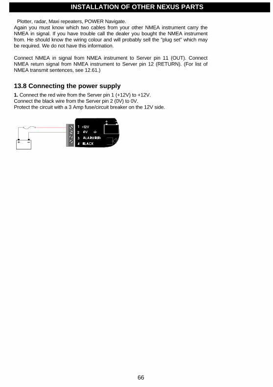
66
Plotter, radar, Maxi repeaters, POWER Navigate.Again you must know which two cables from your other NMEA instrument carry theNMEA in signal. If you have trouble call the dealer you bought the NMEA instrumentfrom. He should know the wiring colour and will probably sell the ”plug set” which maybe required. We do not have this information.
Connect NMEA in signal from NMEA instrument to Server pin 11 (OUT). ConnectNMEA return signal from NMEA instrument to Server pin 12 (RETURN). (For list ofNMEA transmit sentences, see 12.61.)
13.8 Connecting the power supply1. Connect the red wire from the Server pin 1 (+12V) to +12V.Connect the black wire from the Server pin 2 (0V) to 0V.Protect the circuit with a 3 Amp fuse/circuit breaker on the 12V side.
INSTALLATION OF OTHER NEXUS PARTS

67
Note a: Try to keep the power cables as short as possible.Note b: Up to 32 Nexus instrument units (Server, digital and analogue instruments,Autopilot servo-unit or a Nexus GPS) can be connected to the single Nexus data buscable.If more than 10 units are connected, the power must be supplied at both ends of thechain of units, a so-called ”ring-connection”, as shown. Do not connect the Nexus databus wires (yellow and white) in ring-connection.
2. Check that all the connections are correct before you power up the system.
13.9 Compatibility with our previous transducers
13.9.1 Log transducer
All our log transducers (except the transducers from the S-2000 and S-200 series) canbe used for speed and distance.Only transducers from Nexus- and STAR-series are able to measure water temperature.
Note: On the Power transducer the white cable (for water temperature) should be iso-lated and not installed.
INSTALLATION OF OTHER NEXUS PARTS
Screen/Black White Yellow Green/Red
Other transducers
Power D-20S-220S-2200
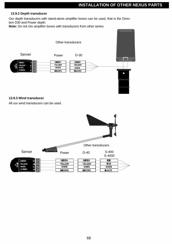
68
13.9.2 Depth transducer
Our depth transducers with stand-alone amplifier boxes can be used, that is the Direc-tion D30 and Power depth.Note: Do not mix amplifier boxes with transducers from other series.
13.9.3 Wind transducer
All our wind transducers can be used.
INSTALLATION OF OTHER NEXUS PARTS
Other transducers
Power D-30
Other transducers
Power D-40 S-400S-4000
Server
Server
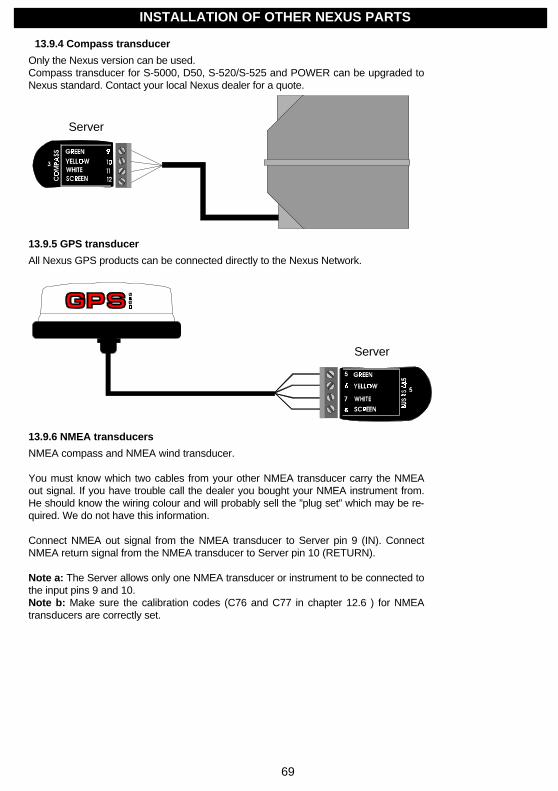
69
13.9.4 Compass transducer
Only the Nexus version can be used.Compass transducer for S-5000, D50, S-520/S-525 and POWER can be upgraded toNexus standard. Contact your local Nexus dealer for a quote.
13.9.5 GPS transducer
All Nexus GPS products can be connected directly to the Nexus Network.
13.9.6 NMEA transducers
NMEA compass and NMEA wind transducer.
You must know which two cables from your other NMEA transducer carry the NMEAout signal. If you have trouble call the dealer you bought your NMEA instrument from.He should know the wiring colour and will probably sell the ”plug set” which may be re-quired. We do not have this information.
Connect NMEA out signal from the NMEA transducer to Server pin 9 (IN). ConnectNMEA return signal from the NMEA transducer to Server pin 10 (RETURN).
Note a: The Server allows only one NMEA transducer or instrument to be connected tothe input pins 9 and 10.Note b: Make sure the calibration codes (C76 and C77 in chapter 12.6 ) for NMEAtransducers are correctly set.
INSTALLATION OF OTHER NEXUS PARTS
Server
Server
70
14 Maintenance and fault finding
14.1 Maintenance• To clean the instrument, use only mild soap solution and rinse with water.• Do not use detergents or high pressure washing equipment.• At least once a year, check all your connections and apply additional silicon paste at each connection
point.• Storing transducers and instruments when not in use for longer periods: It is advisable to remove the
instruments and transducers, and store them inside the boat or at home in room temperature, if possible.
14.2 Fault finding
14.2.1 General
Before you contact your Nexus dealer, and to assist your dealer to give you a better service, please check thefollowing points and make a list of:• All connected instrument and transducers, including their versions.• Nexus Network ID numbers for each instrument (displayed at power up).
In most cases, the reason for faults in electronic equipment is to be found in poor installations. Therefore,always first check that:
• Installation and connection is made per instructions for instrument and transducers.• Screw terminals are carefully tightened.• No corrosion on any connection points.• No loose ends in the wires causing short cuts to adjacent wires.• Cables for damage, that no cables are squeezed or worn.• Battery voltage is sufficient, should be at least 10 V DC.• The fuse is not blown and the circuit breaker has not opened.• The fuse is of the right type.• Two instruments do not have the same ID number.
14.2.2 What you should know about digital depth sounders.
The principle of a depth sounder is that you measure the time it takes for a short acoustic signal to go from thetransducer to bottom and back again to the transducer.
The echo changes due to bottom character, heavy layers of salt and temperature, irregular bottom vegetation,fish etc. Thanks to an advanced signal treatment, these variations will normally not influence the depthmeasurement.
You can in some circumstances get transitory disturbances. In the list below you will find some explanationsfor disturbances to the measurement of depth and how it is expressed on the instrument display.
In general when a boat is moored in a harbour with other boats around, there can be disturbances from signalsfrom other depth transducers, chains or other mooring equipment, which will result in wrong depth readings.
MAINTENANCE AND FAULT FINDING
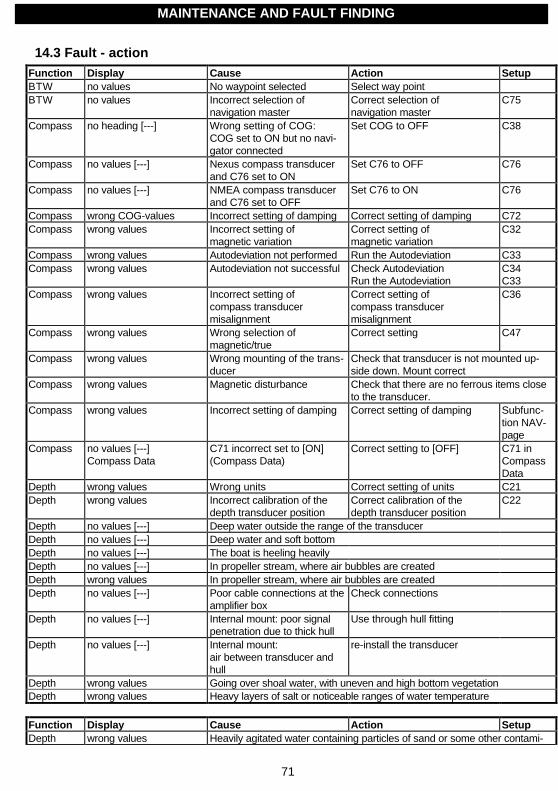
71
14.3 Fault - actionFunction Display Cause Action SetupBTW no values No waypoint selected Select way pointBTW no values Incorrect selection of
navigation masterCorrect selection ofnavigation master
C75
Compass no heading [---] Wrong setting of COG:COG set to ON but no navi-gator connected
Set COG to OFF C38
Compass no values [---] Nexus compass transducerand C76 set to ON
Set C76 to OFF C76
Compass no values [---] NMEA compass transducerand C76 set to OFF
Set C76 to ON C76
Compass wrong COG-values Incorrect setting of damping Correct setting of damping C72Compass wrong values Incorrect setting of
magnetic variationCorrect setting ofmagnetic variation
C32
Compass wrong values Autodeviation not performed Run the Autodeviation C33Compass wrong values Autodeviation not successful Check Autodeviation
Run the AutodeviationC34C33
Compass wrong values Incorrect setting ofcompass transducermisalignment
Correct setting ofcompass transducermisalignment
C36
Compass wrong values Wrong selection ofmagnetic/true
Correct setting C47
Compass wrong values Wrong mounting of the trans-ducer
Check that transducer is not mounted up-side down. Mount correct
Compass wrong values Magnetic disturbance Check that there are no ferrous items closeto the transducer.
Compass wrong values Incorrect setting of damping Correct setting of damping Subfunc-tion NAV-page
Compass no values [---]Compass Data
C71 incorrect set to [ON](Compass Data)
Correct setting to [OFF] C71 inCompassData
Depth wrong values Wrong units Correct setting of units C21Depth wrong values Incorrect calibration of the
depth transducer positionCorrect calibration of thedepth transducer position
C22
Depth no values [---] Deep water outside the range of the transducerDepth no values [---] Deep water and soft bottomDepth no values [---] The boat is heeling heavilyDepth no values [---] In propeller stream, where air bubbles are createdDepth wrong values In propeller stream, where air bubbles are createdDepth no values [---] Poor cable connections at the
amplifier boxCheck connections
Depth no values [---] Internal mount: poor signalpenetration due to thick hull
Use through hull fitting
Depth no values [---] Internal mount:air between transducer andhull
re-install the transducer
Depth wrong values Going over shoal water, with uneven and high bottom vegetationDepth wrong values Heavy layers of salt or noticeable ranges of water temperature
Function Display Cause Action SetupDepth wrong values Heavily agitated water containing particles of sand or some other contami-
MAINTENANCE AND FAULT FINDING

72
nationDepth wrong values
(in harbour / at anchor)Disturbances from other depth transducers
Depth wrong values(in harbour / at anchor)
Disturbances from chains or mooring equipment
DTW no values No waypoint selected Select waypointDTW no values incorrect selection of
navigation masterCorrect selection ofnavigation master
C75
NMEA out no values on NMEA-unit Incorrect selection of NMEAout sentences
Select desired NMEAsentences
C79to C94
NMEA out wrong / no values Poor NMEA-out connection Check connectionsNMEA in wrong / no values Poor NMEA-in connection Check connectionsNMEA in No values Wrong NMEA sentences
transmittedCheck setup in the transmitting unit
Position no values Incorrect selection ofposition source
Correct selection ofposition source
Config Nexus /NMEA position inGPS Navigator
Position wrong values Incorrect setting of compen-sation of latitude and/or lon-gitude
Correct setting of compensa-tion of latitude and/or longi-tude
C39C40
Position wrong values Incorrect setting of localgeodetic datum
Correct setting of localgeodetic datum
C46
Speed no speed [---] Wrong setting of SOG:SOG set to ON but no navi-gator connected
Set SOG to OFF C13
Speed no speed [000] Impeller is not rotating Clean the impellerSpeed no speed [000] Impeller is not rotating, due to
remaining antifouling insidethe through hull fitting
Clean the through-hull fitting
Speed wrong SOG-values Incorrect setting of unit Correct setting of unit C11Speed wrong SOG-values Incorrect setting of damping Correct setting of damping C72Speed wrong values Wrong units Correct setting of units C11Speed wrong values Incorrect calibration value Correct calibration C12Speed wrong values Incorrect setting of damping Correct setting of damping Subfunc-tion
SPEED-pageWind no values [---] Nexus wind transducer
and C77 set to ONSet C77 to OFF C77
Wind no values [---] NMEA wind transducerand C77 set to OFF
Set C77 to ON C77
Wind wrong speed values Wrong units Correct setting of units C52Wind wrong wind angle Wrong selection of
wind angleCorrect selection ofwind angle
C51
Wind wrong wind angle Incorrect setting of masttop unit misalignment
Correct setting of masttop unit misalignment
C54
Wind wrong wind angle Incorrect setting of wind cali-bration values
Correct setting of wind cali-bration values
C55 toC62
Wind wrong values Poor cable connection Check connectionswind transducer / cablethrough deck connectors
Function Display Cause Action SetupWind wrong values Incorrect setting of damping Correct setting of damping Subfunc-tion
WIND-pageWind no values [---]
Wind DataC71 incorrect set to [ON](Wind Data)
Correct setting to [OFF] C71Wind Data
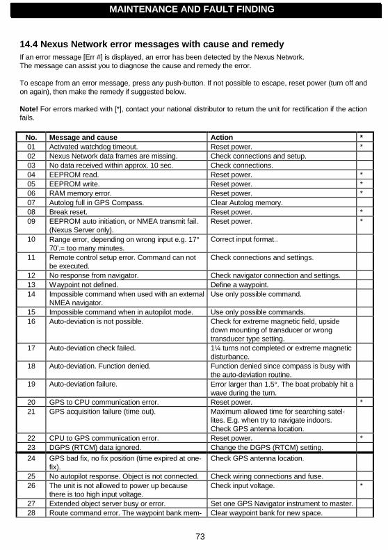
73
14.4 Nexus Network error messages with cause and remedyIf an error message [Err #] is displayed, an error has been detected by the Nexus Network.The message can assist you to diagnose the cause and remedy the error.
To escape from an error message, press any push-button. If not possible to escape, reset power (turn off andon again), then make the remedy if suggested below.
Note! For errors marked with [*], contact your national distributor to return the unit for rectification if the actionfails.
No. Message and cause Action *01 Activated watchdog timeout. Reset power. *02 Nexus Network data frames are missing. Check connections and setup.03 No data received within approx. 10 sec. Check connections.04 EEPROM read. Reset power. *05 EEPROM write. Reset power. *06 RAM memory error. Reset power. *07 Autolog full in GPS Compass. Clear Autolog memory.08 Break reset. Reset power. *09 EEPROM auto initiation, or NMEA transmit fail.
(Nexus Server only).Reset power. *
10 Range error, depending on wrong input e.g. 17°70'.= too many minutes.
Correct input format..
11 Remote control setup error. Command can notbe executed.
Check connections and settings.
12 No response from navigator. Check navigator connection and settings.13 Waypoint not defined. Define a waypoint.14 Impossible command when used with an external
NMEA navigator.Use only possible command.
15 Impossible command when in autopilot mode. Use only possible commands.16 Auto-deviation is not possible. Check for extreme magnetic field, upside
down mounting of transducer or wrongtransducer type setting.
17 Auto-deviation check failed. 1¼ turns not completed or extreme magneticdisturbance.
18 Auto-deviation. Function denied. Function denied since compass is busy withthe auto-deviation routine.
19 Auto-deviation failure. Error larger than 1.5°. The boat probably hit awave during the turn.
20 GPS to CPU communication error. Reset power. *21 GPS acquisition failure (time out). Maximum allowed time for searching satel-
lites. E.g. when try to navigate indoors.Check GPS antenna location.
22 CPU to GPS communication error. Reset power. *23 DGPS (RTCM) data ignored. Change the DGPS (RTCM) setting.
24 GPS bad fix, no fix position (time expired at one-fix).
Check GPS antenna location.
25 No autopilot response. Object is not connected. Check wiring connections and fuse.26 The unit is not allowed to power up because
there is too high input voltage.Check input voltage. *
27 Extended object server busy or error. Set one GPS Navigator instrument to master.28 Route command error. The waypoint bank mem- Clear waypoint bank for new space.
MAINTENANCE AND FAULT FINDINGMAINTENANCE AND FAULT FINDING
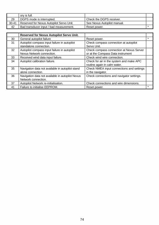
74
ory is full.29 DGPS mode is interrupted. Check the DGPS receiver.
30-41 Reserved for Nexus Autopilot Servo Unit. See Nexus Autopilot manual.42 Bad transducer input / bad measurement. Reset power. *
Reserved for Nexus Autopilot Servo Unit.30 General autopilot failure Reset power. *31 Autopilot compass input failure in autopilot
standalone connection.Check compass connection at autopilotServo Unit.
32 Autopilot compass input failure in autopilotNexus Network connection.
Check compass connection at Nexus Serveror at the Compass Data instrument
33 Received wind data input failure. Check wind wire connection.34 Autopilot calibration failure. Check for air in the system and make APC
routine again in calm water.35 Navigation data not available in autopilot stand
alone connection.Check NMEA input connections and settingsin the navigator.
36 Navigation data not available in autopilot NexusNetwork connection.
Check connections and navigator settings.
37 Autopilot Network re-initialisation. Check connections and wire dimensions.41 Failure to initialise EEPROM. Reset power. *
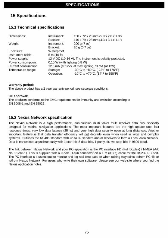
75
15 Specifications
15.1 Technical specifications
Dimensions: Instrument: 150 x 72 x 26 mm (5.9 x 2.8 x 1.0”)Bracket: 110 x 79 x 28 mm (4.3 x 3.1 x 1.1”)
Weight: Instrument: 200 g (7 oz)Bracket: 20 g (0.7 oz)
Enclosure: WaterproofInstrument cable: 5 m (16 ft)Power supply: 12 V DC (10-16 V). The instrument is polarity protected.Power consumption: 0,15 W (with lighting 0,8 W)Current consumption: 12.5 mA (at 12V), at max lighting 70 mA (at 12V)Temperature range: Storage: -30°C to +80°C. (-22°F to 176°F)
Operation: -10°C to +70°C. (14°F to 158°F)
Warranty period:The above product has a 2 year warranty period, see separate conditions.
CE approval:The products conforms to the EMC requirements for immunity and emission according toEN 5008-1 and EN 55022
15.2 Nexus Network specificationThe Nexus Network is a high performance, non-collision multi talker multi receiver data bus, speciallydesigned for marine navigation applications. The most important features are the high update rate, fastresponse times, very low data latency (25ms) and very high data security even at long distances. Anotherimportant feature is that data transfer efficiency will not degrade even when used in large and complexsystems. It utilises the RS485 standard with up to 32 senders and/or receivers to form a Local Area Network.Data is transmitted asynchronously with 1 start-bit, 8-data-bits, 1 parity bit, two stop-bits in 9600 baud.
The link between Nexus Network and your PC-application is the PC interface FD (Full Duplex) / NMEA (Art.No. 21248-1). This is supplied with a 9-pole D-sub connector on a 1 m (3.3 ft) cable for the RS232 PC port.The PC interface is a useful tool to monitor and log real time data, or when editing waypoints to/from PC-file orto/from Nexus Network. For users who write their own software, please see our web-site where you find theNexus application notes.
SPECIFICATIONS
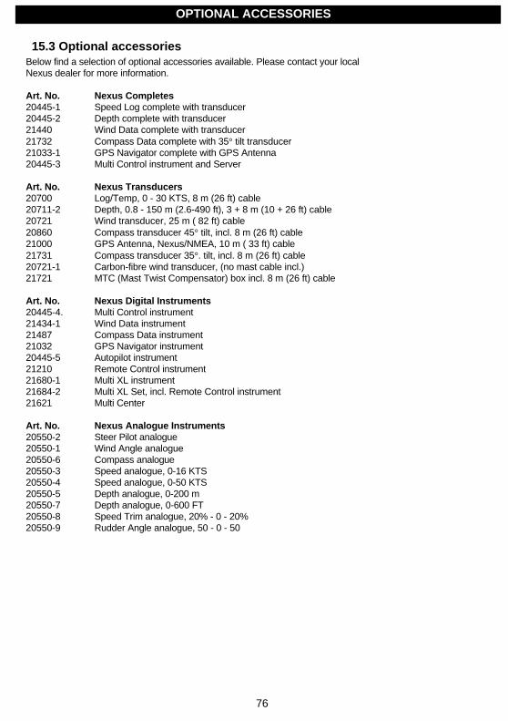
76
15.3 Optional accessoriesBelow find a selection of optional accessories available. Please contact your localNexus dealer for more information.
Art. No. Nexus Completes20445-1 Speed Log complete with transducer20445-2 Depth complete with transducer21440 Wind Data complete with transducer21732 Compass Data complete with 35° tilt transducer21033-1 GPS Navigator complete with GPS Antenna20445-3 Multi Control instrument and Server
Art. No. Nexus Transducers20700 Log/Temp, 0 - 30 KTS, 8 m (26 ft) cable20711-2 Depth, 0.8 - 150 m (2.6-490 ft), 3 + 8 m (10 + 26 ft) cable20721 Wind transducer, 25 m ( 82 ft) cable20860 Compass transducer 45° tilt, incl. 8 m (26 ft) cable21000 GPS Antenna, Nexus/NMEA, 10 m ( 33 ft) cable21731 Compass transducer 35°. tilt, incl. 8 m (26 ft) cable20721-1 Carbon-fibre wind transducer, (no mast cable incl.)21721 MTC (Mast Twist Compensator) box incl. 8 m (26 ft) cable
Art. No. Nexus Digital Instruments20445-4. Multi Control instrument21434-1 Wind Data instrument21487 Compass Data instrument21032 GPS Navigator instrument20445-5 Autopilot instrument21210 Remote Control instrument21680-1 Multi XL instrument21684-2 Multi XL Set, incl. Remote Control instrument21621 Multi Center
Art. No. Nexus Analogue Instruments20550-2 Steer Pilot analogue20550-1 Wind Angle analogue20550-6 Compass analogue20550-3 Speed analogue, 0-16 KTS20550-4 Speed analogue, 0-50 KTS20550-5 Depth analogue, 0-200 m20550-7 Depth analogue, 0-600 FT20550-8 Speed Trim analogue, 20% - 0 - 20%20550-9 Rudder Angle analogue, 50 - 0 - 50
OPTIONAL ACCESSORIES

77
Art. No. Nexus Autopilot21035 Servo Unit21036 Rudder angle transmitter21134 Pumpset 12V PF-0,3, for hydraulic steering21341 Pumpset 12V PF-0,3 with solenoid, for mechanical steering21136-2 Cylinder SP-20, stroke 200 mm
Art. No. Other Nexus Accessories19841 Maxi Repeater yellow digits, NMEA repeater19941 Maxi Repeater red digits, NMEA repeater69999 Mast bracket Maxi, for two Maxi repeaters69995 Mast bracket XL, for Multi XL and standard Nexus 110x11021556 Connection box Nexus Network21453 Connection box Wind Data and Compass incl. 6 m (19 ft) cable21248-1 PC Interface FD (Full Duplex) / NMEA with 1 m (3.3 ft) cable and a 3½”disc.20438 Instrument cover Nexus instruments 110 x 110 mm20443 Nexus extenuation cable, per meter21266-8 Nexus cable 8 m (26 ft) with wire protectors each end20594 Nexus mast cable 25 m (82 ft)
18129 Instrument panel for up to 6 Nexus 110x110 mm instruments19763 Remote push-button for external MOB or Trim function20081 External alarm buzzer, for Nexus Server19038 Internal mounting kit for depth transducer19216 Through hull fitting bronze21154 Paddlewheel blue with axle, high speed 0-50 kts67400-15 Mast top adapter 15° aluminium18500 Through deck connector 7-pole18501 Through deck connector 4-pole20966 Connector 4-pole
Art. No. Common spare parts19488 Rubber screw cover, for instrument front20608 4-pole jack plug, colour coded20608-2 4-pole jack plug, marked 1 2 3 420482 Cover plate 44 mm, for 4-pin connectors21027 Cover plate 60 mm, for 8-pin connectors20535 Wire protection set, 5 pcs x 0,75 mm + 5 pcs x 0,25 mm18490 Paddlewheel red with axle, standard 0-30 kts18884 Through hull fitting plastic incl. nut18990 Dummy plug with o-rings and lock wire18029 O-ring, for log and depth transducer19210 Mast top bracket plastic, for wind transducer
OPTIONAL ACCESSORIES

78
15.4 Abbreviations
Abbreviation DescriptionA AngleAbS AbSolutADJ ADJustALM ALarMANC ANChorANC ANChor alarmAPC Automatic autoPilot CalibrationAQU AcQUisitionARC ARCArrival ArrivalATC Automatic Trim ControlAVS AVerage SpeedAWA Apparent Wind AngleAWS Apparent Wind SpeedBAT BATteryBF BeauFortBOD Bearing Original DestinationBRG BeaRinGBSP Boat SpeedBTW Bearing To waypointC CelciusCal co Calibration codeCE Communaute EuropènneC10 Calibrate 10CAL CalibrateCDI Course Deviation IndicatorCG Course over GroundCHK CHecKCLR CLeaRCMG Course Made GoodCMP CoMPassCOG Course Over GroundCOR CorrectionCRD CouRse DampingCTS Course To Steerd DifferentialD/R Dead ReckoningDAT DATumDEFAULT Facotry settingDEP DEPthDEV DEViationDGPS Differential GPSDMG Distance Made GoodDEA DEpth AlarmDPT DePThDRF DRiFtDST DiSTanceDTW Distance To waypointE EastEDIT EDIT
EEPROM Electrically ErasableProgrammable Read Only
ABBREVIATIONS

79
MemoryEMC Electro Magnetic CompatibilityEN European NormETA Estimated Time or ArrivalF FahrenheitF1-F9 Figure of meritFA FathomFREE FREEFT FeeTGEO GEOdeticGLL Geographic Latitude LongitudeGoTo Go ToGPS Global Positioning SystemHDC HeaDing CompassHDM HeaDing MagneticHDOP Horizontal Dilution Of PrecisionHDT HeaDing TrueHM Heading MagneticHT Heading TrueID IDentityINI INItiationInit InitiationInsert InsertKm Kilometre per hourKT KnoTsKTS KnoTSL LocalLAT LATitudeLCD Liquid Crystal DisplayLEG LEGLGD Local Geodetic DatumLIM LIMitLOG LOGgLON LONgitudeLOW LOWMAG MAGneticMAX MAXimumm/s Meter per secondMEM MEMoryMh Miles per hourMID MIDMIN MINimumMN Magnetic NorthMOB Man Over Boardm MetreN NorthNAV NAVigateNM Nautical MileNMEA National Marine Electronic AssociationNXT NeXTOCA Off Course AlarmPCA Pilot Course AlarmP/S Packets per SecondPWR PoWeRRAM Random Access MemoryRET RETurnRRS RuddeR Speed
ABBREVIATIONS
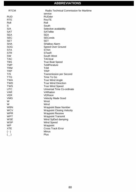
80
RTCM Radio Technical Commission for Maritimeservice
RUD RUDderRTE RouTERoll RollS SouthS/A Selective availabilitySAT SATelliteSEA SEASEC SECondsSET SETSHA SHallow AlarmSOG Speed Over GroundSTA STArtSTR STeeRSW South WestTAC TACticalTBS True Boat SpeedTMP TeMPeratureTRM TriMTRP TRiPT/S Transmission per SecondTTG Time To GoTWA True Wind AngleTWD True Wind DirectionTWS True Wind SpeedUTC Universal Time Co-ordinateVAR VARiationVER VERsionVMG Velocity Made GoodW WestW WindWBN Waypoint Base NumberWCV Waypoint Closing VelocityWPR Waypoint ReceiveWPT Waypoint TransmitWSE Wind SpEed dampingWSP Wind SpeedWP WaypointXTE Cross Track Error( - ) Minus( _ ) Plus
ABBREVIATIONS
81
15.5 Warranty
WARRANTYGENERALAll our products are designed and built to comply with the highest-class industry standards. If the products are cor-rectly installed, maintained and operated, as described in the installation and operation manual, they will providelong and reliable service. Our international Network of distributors can provide you with the information and assis-tance you may require virtually anywhere in the world.Please read through and fill in this warranty card and send it to your national distributor for product reg-istration.
LIMITED WARRANTYThe warranty covers repair of defective parts due to faulty Manufacturing and includes labour when repaired in thecountry of purchase. The warranty period is stated in the product manual, and commences from the date of pur-chase. The above warranty is the Manufacturer’s only warranty and no other terms, expressed or implied, will ap-ply. The Manufacturer specifically excludes the implied warranty of merchantability and fitness for a particular pur-pose.
CONDITIONS• The supplied warranty card and receipt with proof of purchase date must be shown to validate any warrantyclaim. Claims are to be made in accordance with the claims procedure outlined below.• The warranty is non-transferrable and extends only to the original purchaser.• The warranty does not apply to Products from which serial numbers have been removed, faulty installationor incorrect fusing, to conditions resulting from improper use, external causes, including service or modificationsnot performed by the Manufacturer or by its national distributors, or operation outside the environmental parame-ters specified for the Product.• The Manufacturer will not compensate for consequential damage caused directly or indirectly by the mal-function of its equipment. The Manufacturer is not liable for any personal damage caused as a consequence ofusing its equipment.• The Manufacturer, its national distributors or dealers are not liable for charges arising from sea trials, instal-lation surveys or visits to the boat to attend to the equipment, whether under warranty or not. The right is reservedto charge for such services at an appropriate rate.• The Manufacturer reserves the right to replace any products returned for repair, within the warranty period,with the nearest equivalent, if repair within a reasonable time period should not be possible.• The terms and conditions of the warranty as described do not affect your statutory rights.
CLAIMS PROCEDUREEquipment should be returned to the national distributor, or one of its appointed dealers, in the country where itwas originally purchased. Valid claims will then be serviced and returned to the sender free of charge.
Alternatively, if the equipment is being used away from the country of purchase, it may be returned to the nationaldistributor, or one of its appointed dealers, in the country where it is being used. In this case valid claims will coverparts only. Labour and return postage will be invoiced to the sender at an appropriate rate.
DISCLAIMERCommon sense must be used at all times when navigating and the Manufacturer’s navigation equipment shouldonly be considered as aids to navigation.The Manufacturers policy of continuous improvement may result in changes to product specification without priornotice.
WARRANTY

82
File id:
WARRANTY CARDTO BE RETURNED TO YOUR NATIONAL DISTRIBUTOR
OWNER:
Name:
Street:
City/Zip Code:
Country:
Product name: Serial number:
A B C 1 2 3 4 5 67
Date of purchase: _______________________Date installed ______________________________
Dealers stamp:
Tick here if you do not wish to receive news about future products
WARRANTY
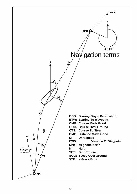
83
Navigation terms
BOD: Bearing Origin DestinationBTW: Bearing To WaypointCMG: Course Made GoodCOG. Course Over GroundCTS: Course To SteerDMG: Distance Made GoodDRF: Drift speedDTW Distance To WaypointMN: Magnetic NorthN: NorthSET: Drift CourseSOG: Speed Over GroundXTE: X-Track Error


![INDEX [ ] · PDF filerudder-design calculations ... bearing carrier, photo.....527 ... fractional sailplan, drawing....497 keel casing, photos](https://img.pdfslide.us/doc/110x75/5aa194617f8b9ac67a8bf8f5/index-calculations-bearing-carrier-photo527-fractional-sailplan.jpg)