Embed Size (px)
Citation preview
25238802 6 -3
INTRODUCTIONThis parts catalog lists replacement parts for the BC-1200 and the BC-1400. The purpose of thisparts catalog is to locate and identify replaceable components and supply information on how toorder them.
Catalog DescriptionThis catalog is divided into major sections labeled with figure numbers, which correspond to theillustrations used. Some assemblies require more than one illustration to identify the parts. Eachpage has a sheet number to identify the sheet as part of that assembly’s parts list.
Replacing parts that are welded or riveted onto an assembly is normally impractical. Therefore,replacement parts are not listed for these items. The assembly containing the welded or riveted partshould be replaced.
Parts List DescriptionThe parts list contains four columns:
• Figure, Sheet, and Index Number — The first entry in this column is the figure number of thecorresponding illustration. An index number, when listed, corresponds to the index numberappearing on the illustration. Index numbers are not used when items are listed for referencepurposes only or when the item listed is an alternate part.
• Rowe Part Number — This column lists the part number to use when ordering replacementparts or making inquiries.
• Description — This column gives a word description of each part or assembly. Each item isindented to show its relationship to the next higher assembly.
• Qty — This column contains the part quantity used in the assembly. When a figure describesmore than one model of an assembly, the “Qty” column is divided to show each model.
Ordering Replacement PartsAll replacement parts must be ordered directly from an Authorized Rowe® Distributor.
Once the replacement item has been determined, complete a Standard Parts Order Form (availablefrom your Rowe® Distributor at no charge). Very often, parts orders are delayed because ofinadequate or incomplete parts order forms. To enable prompt delivery, always specify the followinginformation:
• Part Number and Description (indicate color, if applicable)
• Quantity Required
• Machine Model and Serial Number
• Complete Shipping Address, including the ZIP code
• Shipping Instructions must be supplied. If the shipping method is Parcel Post, Air Parcel Post,United Parcel Service, or Air UPS, and the packages may exceed the size and weight limitsof these services, indicate an alternate shipping method.
If the shipment must be delivered as fast as possible, specify “Fastest Way”. Rowe® will select thecarrier for orders that justify shipment by truck.
6 -4 25238802
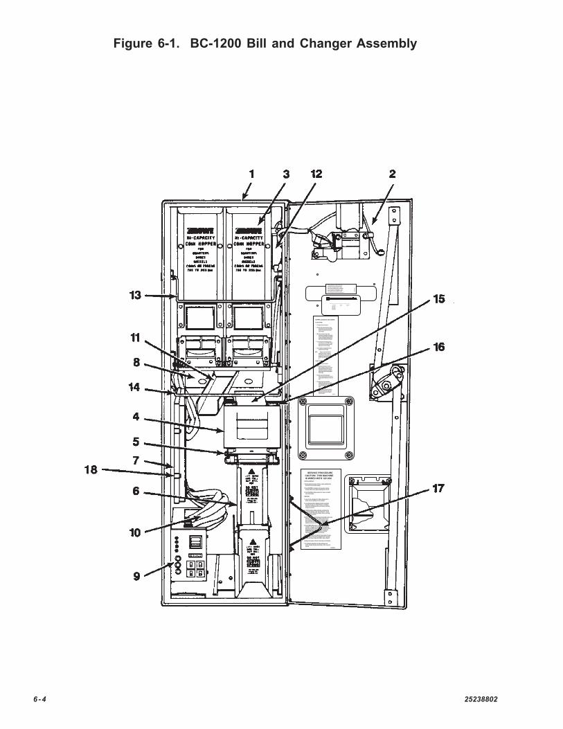
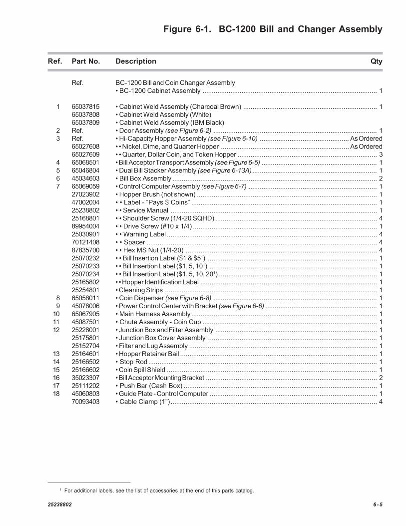
Figure 6-1. BC-1200 Bill and Changer Assembly
"This equipment complies with the re-quirements in Part 15 of FCC Rulesfor Class A computing device. Oper-ation of this equipment in a residentialarea may cause unacceptable interfer-ence to radio and TV reception requir-the operator to take whatever stepsare necessary to correct the interference." 2-
15485-02
MANUFACTURED OR LICENSED UNDER ONE OR MORE OF THE FOLLOWING PATENT NUMBERS:
UNITED STATES
0238201 42232103496542 35613953588354 36903323715031 37666163891970 39102953917260 39660473978958 39640254283708 5704146
RD64093
AUSTRALIA
1475900
GREAT BRITAIN
SERVICE PROCEDURE
STATUS DISPLAY:
since last cleared.
changer to service.
the changer to service.
detectors, hopper, or coins could result in incor-rect change loads in one of the change buckets.After restoring changer to service, always use testswitches to insure corredt change loads in buckets.
cused the changer to go "Out Of Service". Checkand correct the indicated problem before returning
that did not cause an "Out Of Service" condition.Check the indicated problem area before returning
dicate cause of problems in the changer.
changer. Most recent payout displayed on the left.
and forth across status display.
3.A blinking status display indicates a problem that
2.A non-blinking status display indicates a problem
1.Look at status display first. Status display will in-
1.Normal operating mode will have a dash walking back
2.Push [HOPPER] to display last 3 payouts made by
3.Push [VALUE] to display amount of money accepted
Any status code displayed indicating trouble with
IS WIRED WITH 120 VAC
further trouble shooting information, refer to service
after bill was rejected then clear itself.rejected. The status will be displayed for 5 seconds
changer will return to service.
condition. Changer will return to service unless aprevious condition exists. Previous condition will bedisplayed and must also be cleared by pushing[FUNCTION]. When all conditions are cleared,
7.For detailed explanation of status displays and
6.Always turn power off when removing circuit boards.
5.Status display will also indicate reason why a bill was
4.Push [FUNCTION] button to clear displayed status
CAUTION: THIS MACHINE
manual.
SERVICE:
NOTE:
45048908
Hopper msy be loaded with either
3. With open end of bag in hopper, slowly
2. Twist top of full coin bag one full turn. Grasp
1. Pull hopper forward to stop point.
5. Coin I.D. stickers are supplied with machineto identify coin load in hopper.
HOPPER VALUE (HOP VAL) step of setper agree with values programmed inmixed. Make sure value of coins in hop-quarters, dimes, nickels, or tokens un-
HOPPER LOADING & UNLOADING:
TO LOAD HOPPER:
folds of bag. Push hopper back into place.
NOTE:
mouth of hopper.with other. Invert bag and insert top intotwisted top with one hand and hold bottom
at bottom and shaking to dislodge coins incoins into changer. Empty bag by graspingrelease twist as bag empties. Avoid spilling
Repeat process and count change.motor to stop before pressing next switch.test switches one at a time. Wait for hopper
4. Load coin buckets with change by pressing
up.
1. Pull hopper forward to stop point.
hopper, wrapping lip of bag around handle.Grasp bag and handle with one hand, tilthopper back, release latch, and slowly tiphopper forward while holding bag against
2. Place opening of coin bag over mouth of
front of hopper.
times.to upright position. Repeat two or three moreforward. Tap hopper against stop and return
3. Hold bag securely while tipping hopper
when replacing hopper be sure it is securemachine and inverted over bag to empty.
4. The hopper may also be removed from
in pivot brackets and snug against backplate.
other test switches.turn power off, then back on. Repeat fora test switch. When hopper motor starts,
5. Empty change from coin buckets by pressing
35049712
TO EMPTY HOPPER:
R
25238802 6 -5
Figure 6-1. BC-1200 Bill and Changer Assembly
Ref. Part No. Description Qty
Ref. BC-1200 Bill and Coin Changer Assembly• BC-1200 Cabinet Assembly .............................................................................................. 1
1 65037815 • Cabinet Weld Assembly (Charcoal Brown) ........................................................................ 165037808 • Cabinet Weld Assembly (White)65037809 • Cabinet Weld Assembly (IBM Black)
2 Ref. • Door Assembly (see Figure 6-2) ........................................................................................ 13 Ref. • Hi-Capacity Hopper Assembly (see Figure 6-10) ................................................ As Ordered
65027608 • • Nickel, Dime, and Quarter Hopper ..................................................................... As Ordered65027609 • • Quarter, Dollar Coin, and Token Hopper ........................................................................... 3
4 65068501 • Bill Acceptor Transport Assembly (see Figure 6-5) .............................................................. 15 65046804 • Dual Bill Stacker Assembly (see Figure 6-13A) ................................................................... 16 45034603 • Bill Box Assembly .............................................................................................................. 27 65069059 • Control Computer Assembly (see Figure 6-7) ..................................................................... 1
27023902 • Hopper Brush (not shown) ................................................................................................. 147002004 • • Label - “Pays $ Coins” .................................................................................................... 125238802 • • Service Manual ............................................................................................................... 125168801 • • Shoulder Screw (1/4-20 SQHD) ....................................................................................... 489954004 • • Drive Screw (#10 x 1/4) ................................................................................................... 125030901 • • Warning Label ................................................................................................................. 470121408 • • Spacer ............................................................................................................................ 487835700 • • Hex MS Nut (1/4-20) ....................................................................................................... 425070232 • • Bill Insertion Label ($1 & $51) ........................................................................................... 125070233 • • Bill Insertion Label ($1, 5, 101) .......................................................................................... 125070234 • • Bill Insertion Label ($1, 5, 10, 201) ..................................................................................... 125165802 • • Hopper Identification Label ............................................................................................... 125254801 • Cleaning Strips .................................................................................................................. 1
8 65058011 • Coin Dispenser (see Figure 6-8) ........................................................................................ 19 45078006 • Power Control Center with Bracket (see Figure 6-6) ............................................................ 1
10 65067905 • Main Harness Assembly .................................................................................................... 111 45087501 • Chute Assembly - Coin Cup .............................................................................................. 112 25228001 • Junction Box and Filter Assembly ....................................................................................... 1
25175801 • Junction Box Cover Assembly ........................................................................................... 125152704 • Filter and Lug Assembly ..................................................................................................... 1
13 25164601 • Hopper Retainer Bail .......................................................................................................... 114 25166502 • Stop Rod........................................................................................................................... 115 25166602 • Coin Spill Shield ................................................................................................................. 116 35023307 • Bill Acceptor Mounting Bracket ............................................................................................ 217 25111202 • Push Bar (Cash Box) ........................................................................................................ 118 45060803 • Guide Plate - Control Computer .......................................................................................... 1
70093403 • Cable Clamp (1") ............................................................................................................... 4
1 For additional labels, see the list of accessories at the end of this parts catalog.
6 -6 25238802
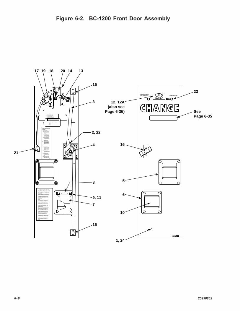
Figure 6-2. BC-1200 Front Door Assembly
OUT OF SERVICETEMPORARILY
MONEY RETURN
"This equipment complies with the re-quirements in Part 15 of FCC Rulesfor Class A computing device. Oper-ation of this equipment in a residentialarea may cause unacceptable interfer-ence to radio and TV reception requir-the operator to take whatever stepsare necessary to correct the interference."
2-15
485-
02
MANUFACTURED OR LICENSED UNDER ONE OR MORE OF THE FOLLOWING PATENT NUMBERS:
UNITED STATES
0238201 42232103496542 35613953588354 36903323715031 37666163891970 39102953917260 39660473978958 39640254283708 5704146
RD64093
AUSTRALIA
1475900
GREAT BRITAIN
SERVICE PROCEDURE
STATUS DISPLAY:
since last cleared.
changer to service.
the changer to service.
detectors, hopper, or coins could result in incor-rect change loads in one of the change buckets.After restoring changer to service, always use testswitches to insure corredt change loads in buckets.
cused the changer to go "Out Of Service". Checkand correct the indicated problem before returning
that did not cause an "Out Of Service" condition.Check the indicated problem area before returning
dicate cause of problems in the changer.
changer. Most recent payout displayed on the left.
and forth across status display.
3.A blinking status display indicates a problem that
2.A non-blinking status display indicates a problem
1.Look at status display first. Status display will in-
1.Normal operating mode will have a dash walking back
2.Push [HOPPER] to display last 3 payouts made by
3.Push [VALUE] to display amount of money accepted
Any status code displayed indicating trouble with
IS WIRED WITH 120 VAC
further trouble shooting information, refer to service
after bill was rejected then clear itself.rejected. The status will be displayed for 5 seconds
changer will return to service.
condition. Changer will return to service unless aprevious condition exists. Previous condition will bedisplayed and must also be cleared by pushing[FUNCTION]. When all conditions are cleared,
7.For detailed explanation of status displays and
6.Always turn power off when removing circuit boards.
5.Status display will also indicate reason why a bill was
4.Push [FUNCTION] button to clear displayed status
CAUTION: THIS MACHINE
manual.
SERVICE:
NOTE:
45048908
Hopper msy be loaded with either
3. With open end of bag in hopper, slowly
2. Twist top of full coin bag one full turn. Grasp
1. Pull hopper forward to stop point.
5. Coin I.D. stickers are supplied with machineto identify coin load in hopper.
HOPPER VALUE (HOP VAL) step of setper agree with values programmed inmixed. Make sure value of coins in hop-quarters, dimes, nickels, or tokens un-
HOPPER LOADING & UNLOADING:
TO LOAD HOPPER:
folds of bag. Push hopper back into place.
NOTE:
mouth of hopper.with other. Invert bag and insert top intotwisted top with one hand and hold bottom
at bottom and shaking to dislodge coins incoins into changer. Empty bag by graspingrelease twist as bag empties. Avoid spilling
Repeat process and count change.motor to stop before pressing next switch.test switches one at a time. Wait for hopper
4. Load coin buckets with change by pressing
up.
1. Pull hopper forward to stop point.
hopper, wrapping lip of bag around handle.Grasp bag and handle with one hand, tilthopper back, release latch, and slowly tiphopper forward while holding bag against
2. Place opening of coin bag over mouth of
front of hopper.
times.to upright position. Repeat two or three moreforward. Tap hopper against stop and return
3. Hold bag securely while tipping hopper
when replacing hopper be sure it is securemachine and inverted over bag to empty.
4. The hopper may also be removed from
in pivot brackets and snug against backplate.
other test switches.turn power off, then back on. Repeat fora test switch. When hopper motor starts,
5. Empty change from coin buckets by pressing
35049712
TO EMPTY HOPPER:
R
21 3 4
21
1, 24
5
16
12, 12A(also see
Page 6-35)
6
10
2, 22
4
7
9, 11
8
3
15
15
131417 18 2019
23
SeePage 6-35
25238802 6 -7
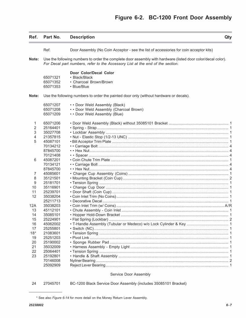
Figure 6-2. BC-1200 Front Door Assembly
Ref. Part No. Description Qty
Ref. Door Assembly (No Coin Acceptor - see the list of accessories for coin acceptor kits)
Note: Use the following numbers to order the complete door assembly with hardware (listed door color/decal color).For Decal part numbers, refer to the Accessory List at the end of the section.
Door Color/Decal Color65071321 • Black/Black65071352 • Charcoal Brown/Brown65071353 • Blue/Blue
Note: Use the following numbers to order the painted door only (without hardware or decals).
65071207 • • Door Weld Assembly (Black)65071208 • • Door Weld Assembly (Charcoal Brown)65071209 • • Door Weld Assembly (Blue)
1 65071206 • Door Weld Assembly (Black) without 35085101 Bracket ........................................................ 12 25164401 • Spring - Strap ........................................................................................................................... 13 35027708 • Lockbar Assembly ................................................................................................................... 14 21357815 • Nut - Elastic Stop (1/2-13 UNC) .............................................................................................. 15 45087101 • Bill Acceptor Trim Plate ............................................................................................................. 1
70134212 • • Carriage Bolt .......................................................................................................................... 487845700 • • Hex Nut .................................................................................................................................. 470121408 • • Spacer ................................................................................................................................... 4
6 45087201 • Coin Chute Trim Plate .............................................................................................................. 170134121 • • Carriage Bolt .......................................................................................................................... 487845700 • • Hex Nut .................................................................................................................................. 4
7 45085601 • Change Cup Assembly (Coins) .............................................................................................. 18 35121501 • Mounting Bracket (Coin Cup) ................................................................................................... 29 25181701 • Tension Spring ......................................................................................................................... 1
10 35116901 • Change Cup Door ................................................................................................................... 111 25239701 • Door Shaft (Coin Cup) ............................................................................................................. 112 35038204 • Coin Inlet Trim (No Coins) ......................................................................................................... 1
25211713 • Decorative Decal ...................................................................................................................... 112A 35038203 • Coin Inlet Trim (w/ Coins) ..................................................................................................... A/R
13 45112101 • Chute Assembly - Coin Inlet .................................................................................................... 114 35085101 • Hopper Hold-Down Bracket ..................................................................................................... 115 25224901 • Flat Spring (Lockbar) ................................................................................................................ 216 45062002 • T-Handle Assembly (Tubular or Medeco) w/o Lock Cylinder & Key ....................................... 117 25255801 • Switch (NC) .............................................................................................................................. 1
18* 21083601 • Tension Spring ......................................................................................................................... 119 25251203 • Pivot Link .................................................................................................................................. 120 25190002 • Sponge Rubber Pad ............................................................................................................... 121 35032009 • Harness Assembly - Empty Light ............................................................................................ 122 25064401 • Tension Spring ......................................................................................................................... 123 25192801 • Handle & Shaft Assembly ....................................................................................................... 1
70146008 Nyliner Bearing ............................................................................................................................ 225092909 Reject Lever Bearing................................................................................................................... 1
Service Door Assembly
24 27045701 BC-1200 Black Service Door Assembly (includes 35085101 Bracket)
* See also Figure 6-14 for more detail on the Money Return Lever Assembly.
6 -8 25238802
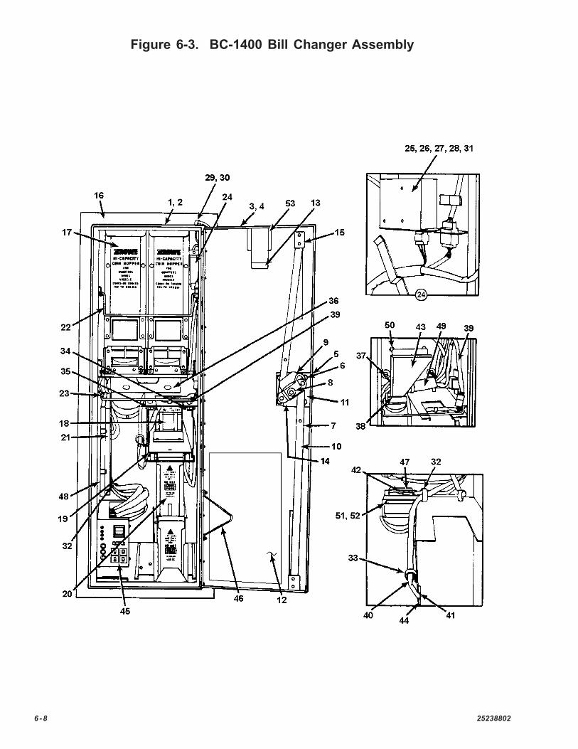
Figure 6-3. BC-1400 Bill Changer Assembly
25238802 6 -9
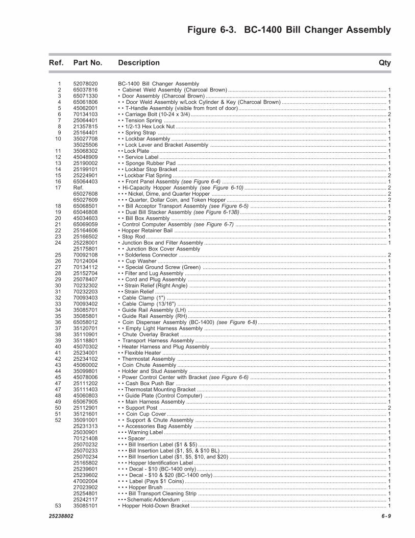
Figure 6-3. BC-1400 Bill Changer Assembly
Ref. Part No. Description Qty
1 52078020 BC-1400 Bill Changer Assembly2 65037816 • Cabinet Weld Assembly (Charcoal Brown) .......................................................................................................... 13 65071330 • Door Assembly (Charcoal Brown) ......................................................................................................................... 14 65061806 • • Door Weld Assembly w/Lock Cylinder & Key (Charcoal Brown) ...................................................................... 15 45062001 • • T-Handle Assembly (visible from front of door) ................................................................................................... 16 70134103 • • Carriage Bolt (10-24 x 3/4) ................................................................................................................................... 27 25064401 • • Tension Spring ..................................................................................................................................................... 18 21357815 • • 1/2-13 Hex Lock Nut ............................................................................................................................................. 19 25164401 • • Spring Strap ......................................................................................................................................................... 1
10 35027708 • • Lockbar Assembly ................................................................................................................................................ 135025506 • • Lock Lever and Bracket Assembly ...................................................................................................................... 1
11 35068302 • • Lock Plate .............................................................................................................................................................. 112 45048909 • • Service Label ........................................................................................................................................................ 113 25190002 • • Sponge Rubber Pad ............................................................................................................................................ 114 25199101 • • Lockbar Stop Bracket ........................................................................................................................................... 115 25224901 • • Lockbar Flat Spring ............................................................................................................................................... 216 65064403 • • Front Panel Assembly (see Figure 6-4) .............................................................................................................. 117 Ref. • Hi-Capacity Hopper Assembly (see Figure 6-10) ............................................................................................... 2
65027608 • • • Nickel, Dime, and Quarter Hopper ..................................................................................................................... 265027609 • • • Quarter, Dollar Coin, and Token Hopper ........................................................................................................... 2
18 65068501 • • Bill Acceptor Transport Assembly (see Figure 6-5) ........................................................................................... 119 65046808 • • Dual Bill Stacker Assembly (see Figure 6-13B) .................................................................................................. 120 45034603 • • Bill Box Assembly ................................................................................................................................................ 221 65069059 • Control Computer Assembly (see Figure 6-7) ..................................................................................................... 122 25164606 • Hopper Retainer Bail .............................................................................................................................................. 123 25166502 • Stop Rod ................................................................................................................................................................. 124 25228001 • Junction Box and Filter Assembly .......................................................................................................................... 1
25175801 • • Junction Box Cover Assembly25 70092108 • • Solderless Connector ........................................................................................................................................... 226 70124004 • • Cup Washer ......................................................................................................................................................... 127 70134112 • • Special Ground Screw (Green) ........................................................................................................................... 128 25152704 • • Filter and Lug Assembly ....................................................................................................................................... 129 25078407 • • Cord and Plug Assembly ..................................................................................................................................... 130 70232302 • • Strain Relief (Right Angle) .................................................................................................................................... 131 70232203 • • Strain Relief ........................................................................................................................................................... 132 70093403 • Cable Clamp (1") ................................................................................................................................................... 133 70093402 • Cable Clamp (13/16") ............................................................................................................................................ 134 35085701 • Guide Rail Assembly (LH) ..................................................................................................................................... 235 35085801 • Guide Rail Assembly (RH) ..................................................................................................................................... 136 65058012 • Coin Dispenser Assembly (BC-1400) (see Figure 6-8) ...................................................................................... 137 35120701 • • Empty Light Harness Assembly .......................................................................................................................... 138 35110901 • Chute Overlay Bracket .......................................................................................................................................... 139 35118801 • Transport Harness Assembly ................................................................................................................................ 140 45070302 • Heater Harness and Plug Assembly ...................................................................................................................... 141 25234001 • • Flexible Heater ...................................................................................................................................................... 142 25234102 • Thermostat Assembly ............................................................................................................................................ 143 45060002 • Coin Chute Assembly ............................................................................................................................................ 144 35099801 • Holder and Stud Assembly .................................................................................................................................... 145 45078006 • Power Control Center with Bracket (see Figure 6-6) ........................................................................................... 147 25111202 • • Cash Box Push Bar ............................................................................................................................................. 147 35111403 • • Thermostat Mounting Bracket ............................................................................................................................... 148 45060803 • • Guide Plate (Control Computer) .......................................................................................................................... 149 65067905 • • Main Harness Assembly ...................................................................................................................................... 150 25112901 • • Support Post ........................................................................................................................................................ 251 35121601 • • Coin Cup Cover ................................................................................................................................................... 152 35091001 • • Support & Chute Assembly ................................................................................................................................ 1
25231313 • • Accessories Bag Assembly ................................................................................................................................. 125030901 • • • Warning Label ..................................................................................................................................................... 170121408 • • • Spacer ................................................................................................................................................................. 125070232 • • • Bill Insertion Label ($1 & $5) .............................................................................................................................. 125070233 • • • Bill Insertion Label ($1, $5, & $10 BL) ............................................................................................................... 125070234 • • • Bill Insertion Label ($1, $5, $10, and $20) ......................................................................................................... 125165802 • • • Hopper Identification Label ................................................................................................................................. 125239601 • • • Decal - $10 (BC-1400 only) ............................................................................................................................... 125239602 • • • Decal - $10 & $20 (BC-1400 only) .................................................................................................................... 147002004 • • • Label (Pays $1 Coins) ....................................................................................................................................... 127023902 • • • Hopper Brush ..................................................................................................................................................... 125254801 • • • Bill Transport Cleaning Strip .............................................................................................................................. 125242117 • • • Schematic Addendum ......................................................................................................................................... 1
53 35085101 • Hopper Hold-Down Bracket ................................................................................................................................... 1

6-10 25238802
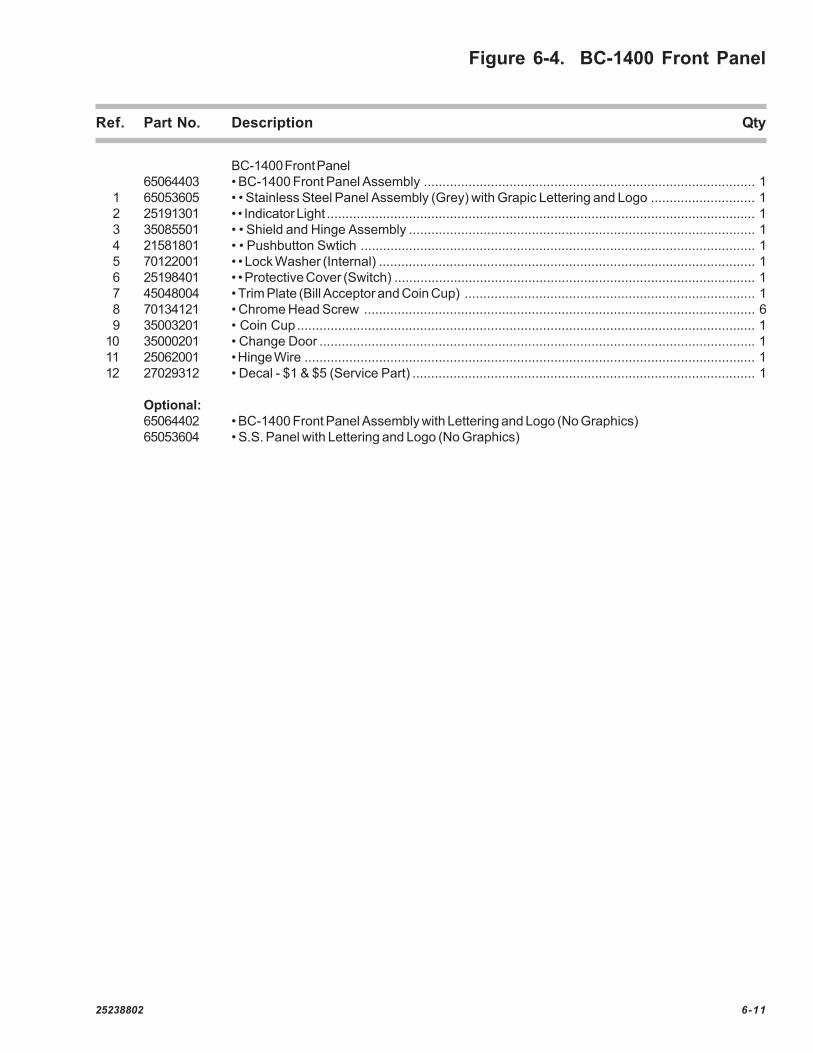
Figure 6-4. BC-1400 Front Panel
1
2
3
4, 5, 6
7
8
9
10, 11
12
See Page 6-37
25238802 6-11
Figure 6-4. BC-1400 Front Panel
Ref. Part No. Description Qty
BC-1400 Front Panel65064403 • BC-1400 Front Panel Assembly ......................................................................................... 1
1 65053605 • • Stainless Steel Panel Assembly (Grey) with Grapic Lettering and Logo ............................ 12 25191301 • • Indicator Light ................................................................................................................... 13 35085501 • • Shield and Hinge Assembly ............................................................................................. 14 21581801 • • Pushbutton Swtich .......................................................................................................... 15 70122001 • • Lock Washer (Internal) ..................................................................................................... 16 25198401 • • Protective Cover (Switch) ................................................................................................. 17 45048004 • Trim Plate (Bill Acceptor and Coin Cup) .............................................................................. 18 70134121 • Chrome Head Screw ......................................................................................................... 69 35003201 • Coin Cup........................................................................................................................... 1
10 35000201 • Change Door ..................................................................................................................... 111 25062001 • Hinge Wire ......................................................................................................................... 112 27029312 • Decal - $1 & $5 (Service Part) ............................................................................................ 1
Optional:65064402 • BC-1400 Front Panel Assembly with Lettering and Logo (No Graphics)65053604 • S.S. Panel with Lettering and Logo (No Graphics)

6-12 25238802
Figure 6-5. BA-50 Bill Acceptor Assembly(Corresponding Parts List on page 6-14)

25238802 6-13
6-14 25238802
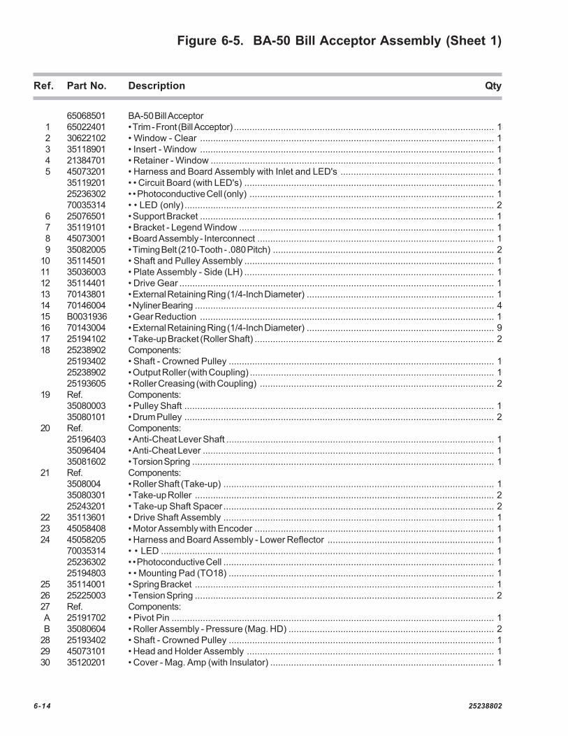
Figure 6-5. BA-50 Bill Acceptor Assembly (Sheet 1)
Ref. Part No. Description Qty
65068501 BA-50 Bill Acceptor1 65022401 • Trim - Front (Bill Acceptor) .................................................................................................... 12 30622102 • Window - Clear ................................................................................................................. 13 35118901 • Insert - Window ................................................................................................................. 14 21384701 • Retainer - Window ............................................................................................................. 15 45073201 • Harness and Board Assembly with Inlet and LED's ........................................................... 1
35119201 • • Circuit Board (with LED's) ................................................................................................ 125236302 • • Photoconductive Cell (only) .............................................................................................. 170035314 • • LED (only) ....................................................................................................................... 2
6 25076501 • Support Bracket ................................................................................................................. 17 35119101 • Bracket - Legend Window .................................................................................................. 18 45073001 • Board Assembly - Interconnect ........................................................................................... 19 35082005 • Timing Belt (210-Tooth - .080 Pitch) ..................................................................................... 2
10 35114501 • Shaft and Pulley Assembly ................................................................................................ 111 35036003 • Plate Assembly - Side (LH) ................................................................................................ 112 35114401 • Drive Gear ......................................................................................................................... 113 70143801 • External Retaining Ring (1/4-Inch Diameter) ........................................................................ 114 70146004 • Nyliner Bearing ................................................................................................................... 415 B0031936 • Gear Reduction ................................................................................................................. 116 70143004 • External Retaining Ring (1/4-Inch Diameter) ........................................................................ 917 25194102 • Take-up Bracket (Roller Shaft) ............................................................................................ 218 25238902 Components:
25193402 • Shaft - Crowned Pulley ...................................................................................................... 125238902 • Output Roller (with Coupling) .............................................................................................. 125193605 • Roller Creasing (with Coupling) .......................................................................................... 2
19 Ref. Components:35080003 • Pulley Shaft ....................................................................................................................... 135080101 • Drum Pulley ....................................................................................................................... 2
20 Ref. Components:25196403 • Anti-Cheat Lever Shaft ....................................................................................................... 135096404 • Anti-Cheat Lever ................................................................................................................ 135081602 • Torsion Spring .................................................................................................................... 1
21 Ref. Components:3508004 • Roller Shaft (Take-up) ........................................................................................................ 135080301 • Take-up Roller ................................................................................................................... 225243201 • Take-up Shaft Spacer ........................................................................................................ 2
22 35113601 • Drive Shaft Assembly ........................................................................................................ 123 45058408 • Motor Assembly with Encoder ............................................................................................ 124 45058205 • Harness and Board Assembly - Lower Reflector ................................................................ 1
70035314 • • LED ................................................................................................................................ 125236302 • • Photoconductive Cell ........................................................................................................ 125194803 • • Mounting Pad (TO18) ...................................................................................................... 1
25 35114001 • Spring Bracket ................................................................................................................... 126 25225003 • Tension Spring ................................................................................................................... 227 Ref. Components:A 25191702 • Pivot Pin ............................................................................................................................ 1B 35080604 • Roller Assembly - Pressure (Mag. HD) ............................................................................... 2
28 25193402 • Shaft - Crowned Pulley ...................................................................................................... 129 45073101 • Head and Holder Assembly ............................................................................................... 130 35120201 • Cover - Mag. Amp (with Insulator) ...................................................................................... 1

25238802 6-15
Figure 6-5. BA-50 Bill Acceptor Assembly (Sheet 2)
Ref. Part No. Description Qty
31 35118501 • Harness and Bracket Assembly - Mag. Amp...................................................................... 125240801 • • Mounting Bracket Assembly (Sensor) ............................................................................... 121814009 • • Hex Lock Nut ................................................................................................................... 145073301 • • Harness & Board Assembly - Mag. Amp ......................................................................... 1
32 65067101 • Track - Lower ..................................................................................................................... 133 35114901 • Drive Belt (Upper) .............................................................................................................. 234 21342702 • Retaining Spring (Roller) ..................................................................................................... 335 25235001 • Roller Shaft ........................................................................................................................ 336 65067501 • Bill Inlet (Upper) .................................................................................................................. 137 25060101 • Bracket Side Shield ............................................................................................................ 238 65067601 • Bill Inlet (Lower) .................................................................................................................. 139 35035209 • Plate Assembly - Side (RH) ............................................................................................... 140 21398501 • Tension Spring ................................................................................................................... 141 20922510 • Spacer .............................................................................................................................. 142 35126501 • Anti-Cheat Lever (Pull Back) .............................................................................................. 143 25079801 • Lug .................................................................................................................................... 144 25223101 • Flag Label ......................................................................................................................... 145 35104002 • Output Drive Guide ............................................................................................................ 146 35147301 • Anti-Pullback Block ............................................................................................................. 147 21776005 • Speed Clip Fastener (U Type) ........................................................................................... 148 35080003 • Pulley Shaft ....................................................................................................................... 149 35080101 • Pulley ................................................................................................................................ 250 35080004 • Roller Shaft (Take-Up)........................................................................................................ 151 35080301 • Take-Up Roller ................................................................................................................... 252 25243201 • Shaft Spacer (Take-Up Roller) ........................................................................................... 253 25191702 • Pivot Pin ............................................................................................................................ 154 35080604 • Pressure Roller Assembly .................................................................................................. 255 25193301 • Crowned Roller .................................................................................................................. 456 25193902 • Roller - Idler (Input) ............................................................................................................. 157 70120915 • Washer ............................................................................................................................. 458 25192902 • Timing Pulley (22-Tooth) ..................................................................................................... 159 70143301 • External Retaining Ring ...................................................................................................... 2
HARDWARE LIST
A 80653006 #8-32 x 3/8 Hex HMS .......................................................................................................... 1B 87843000 #8-32 Keps Hex MS Nut ...................................................................................................... 1C 89293007 #8-18 x 7/16 Hex WRHS (Hi-Lo) .......................................................................................... 6D 80443008 #8-32 x 1/2 Hex WRHMS (SF) ............................................................................................. 8E 80443006 #8-32 x 3/8 Hex WRHMS (SF) ............................................................................................. 9F 80443004 #8-32 x 1/4 Hex WRHMS (Hi-Lo) ......................................................................................... 7
G 89292307 #6-19 x 7/16 Hex WRHS (Hi-Lo) .......................................................................................... 2H 89281605 #4-24 x 5/16 Phil Pan RO HS (Hi-Lo) ................................................................................... 3I 80542304 #6-32 x 1/4 Sems Phil RO HMS .......................................................................................... 2J 80384405 #10-32 x 5/16 Phil Pan HMS (SF) ........................................................................................ 1K 80403004 #8-32 x 1/4 Phil Pan HMS (SF) ............................................................................................ 3L 80383006 #8-32 x 3/8 P.R. HMS (SF) .................................................................................................. 1
M 87842300 #6-32 Keps Hex MS Nut ...................................................................................................... 4N 88903000 #8 External Lockwasher ....................................................................................................... 2O 80443007 #8-32 x 7/16 Hex WHS (Swage Form) ................................................................................. 2

6-16 25238802
Figure 6-6. Power Control Center Assembly
30VDC
40VDC
5VDC
12VDC
TEST
SWITCHES
ON
OFF
CB201CB203 4
0
B
02
C2
C
2B
DOLLARS ACCEPTED
POWER CONTROL CENTER65073504
L
C
R
Q801
S801
R831
R804
Q802
L804
P801
D814
D813
R823
C809
L803
P807
D818
D816
C813
R829
C810
R824
C814
C803
P802
P808
H4
HS2
VR801
C801
C807
C804
D809
P803
H3
C808
C802
D812
VR802
C811
R834
D808
R812
R811
R810
R809
P804
K801
C815
P805
1
1 1
1
1 1
1
PMA7 5
AMP
2AMP
7AMP
P806
7
18
5
69
1112 1015
32
8
1716 4 13 14
1
25238802 6-17
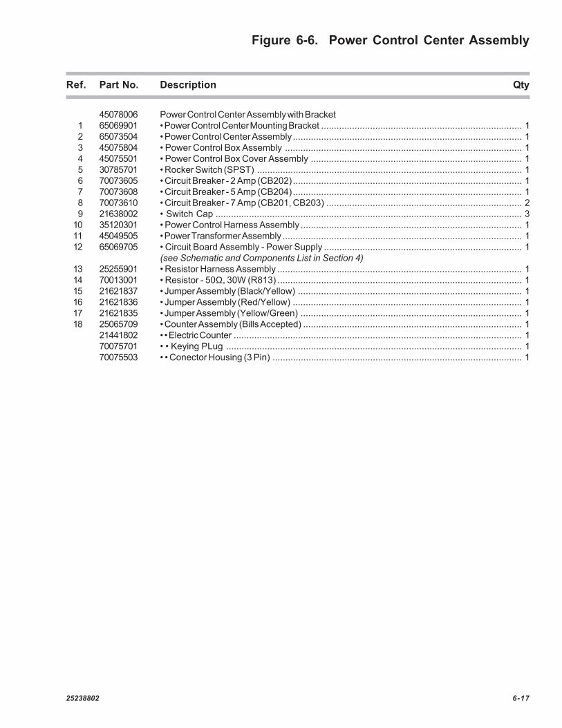
Figure 6-6. Power Control Center Assembly
Ref. Part No. Description Qty
45078006 Power Control Center Assembly with Bracket1 65069901 • Power Control Center Mounting Bracket .............................................................................. 12 65073504 • Power Control Center Assembly......................................................................................... 13 45075804 • Power Control Box Assembly ............................................................................................ 14 45075501 • Power Control Box Cover Assembly .................................................................................. 15 30785701 • Rocker Switch (SPST) ....................................................................................................... 16 70073605 • Circuit Breaker - 2 Amp (CB202)......................................................................................... 17 70073608 • Circuit Breaker - 5 Amp (CB204)......................................................................................... 18 70073610 • Circuit Breaker - 7 Amp (CB201, CB203) ............................................................................ 29 21638002 • Switch Cap ....................................................................................................................... 3
10 35120301 • Power Control Harness Assembly ...................................................................................... 111 45049505 • Power Transformer Assembly ............................................................................................. 112 65069705 • Circuit Board Assembly - Power Supply ............................................................................. 1
(see Schematic and Components List in Section 4)13 25255901 • Resistor Harness Assembly ............................................................................................... 114 70013001 • Resistor - 50Ω, 30W (R813) ............................................................................................... 115 21621837 • Jumper Assembly (Black/Yellow) ....................................................................................... 116 21621836 • Jumper Assembly (Red/Yellow) ......................................................................................... 117 21621835 • Jumper Assembly (Yellow/Green) ...................................................................................... 118 25065709 • Counter Assembly (Bills Accepted) ..................................................................................... 1
21441802 • • Electric Counter ................................................................................................................ 170075701 • • Keying PLug ................................................................................................................... 170075503 • • Conector Housing (3 Pin) ................................................................................................. 1
6-18 25238802
Figure 6-7. Control Computer Assembly
HOPPER
CNTRLEFT RIGHT
PROGRAMMING MODE
NORMAL OPERATING MODE
FUNCTION - ERROR RESET
HOPPER
VALUE
NOTE:PRESS FUNCTION - ERROR RESETBUTTON TO CLEAR DISPLAYED ERROR
COUNTSWITCHES
EITHER BUTTON ACTS AS YES/NO,ON/OFF, ALT/SEP, OR UPPER/LOWER
PRESS BOTH BUTTONS TO CLEARDISPLAYED TEMPORARY COUNTER
1
4
BILL CHANGERCONTROL COMPUTER
65069059
P6
P1
P2
P3
P4
P5
12
14
1
15
1
8
1
1
91
12
3
4
25238802 6-19
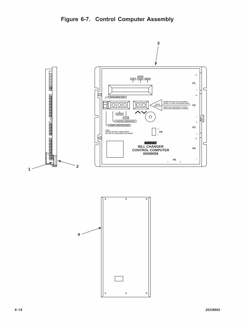
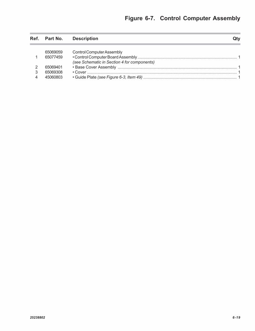
Figure 6-7. Control Computer Assembly
Ref. Part No. Description Qty
65069059 Control Computer Assembly1 65077459 • Control Computer Board Assembly ..................................................................................... 1
(see Schematic in Section 4 for components)2 65069401 • Base Cover Assembly ...................................................................................................... 13 65069308 • Cover ................................................................................................................................ 14 45060803 • Guide Plate (see Figure 6-3, Item 49) ................................................................................ 1

6-20 25238802
Figure 6-8. Coin Dispenser Assembly
9
10
15, 16, 17
8
17
4
19
18
13
2
12
14
6
511
20
3

25238802 6-21
Figure 6-8. Coin Dispenser Assembly
Ref. Part No. Description Qty
Ref. Coin Dispenser Assembly65058011 • BC-1200 only65058012 • BC-1400 only
Both the BC-1200 and the BC-1400 use the same components, except as noted.
1 45035311 • Frame and Pivot Assembly ................................................................................................ 12 Ref. • Change Bucket Assembly ................................................................................................. 1
45032615 • BC-1200 only (see Figure 6-9)45032616 • BC-1400 only (see Figure 6-9)
3 35044702 • Mounting Bracket (Hopper LH) ........................................................................................... 24 35044802 • Mounting Bracket (Hopper RH) ........................................................................................... 25 35049102 • Hopper Drive Motor Assembly ........................................................................................... 2
45034102 • • Hopper Drive Motor45034001 • • Ratchet Coupling25097701 • • Compression Spring70120904 • • Washer (Nylon)70110126 • • Groove Pin (1/8 x 3/4)37004601 • • Gear Box
6 35046401 • Mounting Bracket (Motor) .................................................................................................... 27 25112701 • Rubber Bumper ................................................................................................................. 28 45076101 • LED Holder Assembly........................................................................................................ 2
70035315 • • LED ................................................................................................................................ 29 70093106 • Cable Clamp (7/16") .......................................................................................................... 2
10 45035006 • Chute Assembly ................................................................................................................ 111 65029114 • Dispenser Harness Assembly ........................................................................................... 112 35068202 • Chute Assembly - Coin Weld (BC-1200 only) ..................................................................... 113 25169106 • • Dispenser Wiring Label .................................................................................................... 114 25163902 • Dispenser Bucket Lube Label ............................................................................................ 115 25175702 • Photodetector Board and Terminal Assembly ...................................................................... 216 70121626 • Spacer (Nylon) ................................................................................................................... 217 35048202 • Terminal Board Cover ......................................................................................................... 218 35125401 • Hopper Latch Assembly .................................................................................................... 119 45042602 • Dispenser Motor Guard ...................................................................................................... 120 45076402 • Circuit Board Assembly - Interconnect ................................................................................. 1A 70035006 • • Diode .............................................................................................................................. 3
25189411 • Coin Dispenser Label ........................................................................................................ 1
6-22 25238802
Figure 6-9. Change Bucket Assembly
25238802 6-23
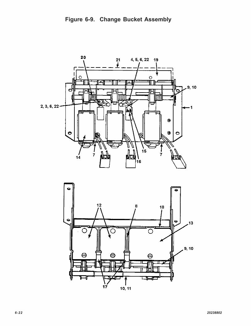
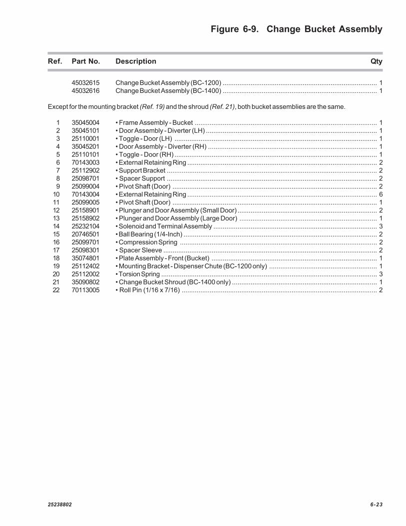
Figure 6-9. Change Bucket Assembly
Ref. Part No. Description Qty
45032615 Change Bucket Assembly (BC-1200) ................................................................................... 145032616 Change Bucket Assembly (BC-1400) ................................................................................... 1
Except for the mounting bracket (Ref. 19) and the shroud (Ref. 21), both bucket assemblies are the same.
1 35045004 • Frame Assembly - Bucket .................................................................................................. 12 35045101 • Door Assembly - Diverter (LH) ............................................................................................ 13 25110001 • Toggle - Door (LH) ............................................................................................................. 14 35045201 • Door Assembly - Diverter (RH) ........................................................................................... 15 25110101 • Toggle - Door (RH) ............................................................................................................. 16 70143003 • External Retaining Ring ...................................................................................................... 27 25112902 • Support Bracket ................................................................................................................. 28 25098701 • Spacer Support ................................................................................................................. 29 25099004 • Pivot Shaft (Door) .............................................................................................................. 2
10 70143004 • External Retaining Ring ...................................................................................................... 611 25099005 • Pivot Shaft (Door) .............................................................................................................. 112 25158901 • Plunger and Door Assembly (Small Door) ........................................................................... 213 25158902 • Plunger and Door Assembly (Large Door) .......................................................................... 114 25232104 • Solenoid and Terminal Assembly ........................................................................................ 315 20746501 • Ball Bearing (1/4-Inch) ........................................................................................................ 216 25099701 • Compression Spring .......................................................................................................... 217 25098301 • Spacer Sleeve ................................................................................................................... 218 35074801 • Plate Assembly - Front (Bucket) ......................................................................................... 119 25112402 • Mounting Bracket - Dispenser Chute (BC-1200 only) .......................................................... 120 25112002 • Torsion Spring .................................................................................................................... 321 35090802 • Change Bucket Shroud (BC-1400 only) .............................................................................. 122 70113005 • Roll Pin (1/16 x 7/16) ......................................................................................................... 2
6-24 25238802
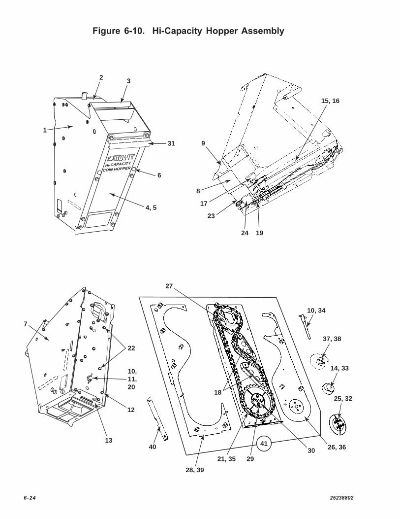
Figure 6-10. Hi-Capacity Hopper Assembly
R
HI-CAPACITY
COIN HOPPER
1
4, 5
31
3
6
2
8
17
23
24 19
9
15, 16
7
10,11,20
22
13
12
10, 34
37, 38
302921, 35
40
18
27
41
28, 39
14, 33
25, 32
26, 36
25238802 6-25
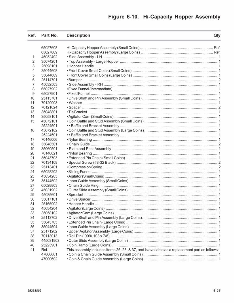
Figure 6-10. Hi-Capacity Hopper Assembly
Ref. Part No. Description Qty
65027608 Hi-Capacity Hopper Assembly (Small Coins) .................................................................... Ref.65027609 Hi-Capacity Hopper Assembly (Large Coins) ................................................................... Ref.
1 45032402 • Side Assembly - LH ........................................................................................................... 12 35074201 • Top Assembly - Large Hopper ........................................................................................... 13 25098101 • Hopper Handle .................................................................................................................. 14 35044608 • Front Cover Small Coins (Small Coins) ............................................................................... 15 35044609 • Front Cover Small Coins (Large Coins) ............................................................................... 16 25114701 • Bumper.............................................................................................................................. 27 45032503 • Side Assembly - RH .......................................................................................................... 18 65027902 • Fixed Funnel (Intermediate) ................................................................................................. 19 65027901 • Fixed Funnel ...................................................................................................................... 1
10 25113701 • Drive Shaft and Pin Assembly (Small Coins) ...................................................................... 111 70120903 • Washer ............................................................................................................................. 112 70121624 • Spacer .............................................................................................................................. 213 35048801 • Tie Bracket ......................................................................................................................... 114 35058101 • Agitator Cam (Small Coins) ................................................................................................ 115 45072101 • Coin Baffle and Stud Assembly (Small Coins) .................................................................... 1
25224501 • • Baffle and Bracket Assembly ........................................................................................... 116 45072102 • Coin Baffle and Stud Assembly (Large Coins) .................................................................... 1
25224501 • • Baffle and Bracket Assembly ........................................................................................... 117 70146006 • Nylon Bearing .................................................................................................................... 118 35048501 • Chain Guide ...................................................................................................................... 219 35060501 • Plate and Post Assembly .................................................................................................. 120 70146021 • Nylon Bearing .................................................................................................................... 121 35043703 • Extended Pin Chain (Small Coins) ..................................................................................... 122 70134109 • Special Screw (#8-32 Black) .............................................................................................. 223 25113401 • Compression Spring .......................................................................................................... 224 65028202 • Sliding Funnel ..................................................................................................................... 125 45034205 • Agitator (Small Coins) ......................................................................................................... 126 35144502 • Inner Guide Assembly (Small Coins) .................................................................................. 127 65028803 • Chain Guide Ring .............................................................................................................. 128 45031902 • Outer Slide Assembly (Small Coins) ................................................................................... 129 45035601 • Sprocket ............................................................................................................................ 130 35017101 • Drive Spacer ..................................................................................................................... 131 25165902 • Hopper Handle .................................................................................................................. 132 45034204 • Agitator (Large Coins) ........................................................................................................ 133 35058102 • Agitator Cam (Large Coins) ................................................................................................ 134 25113702 • Drive Shaft and Pin Assembly (Large Coins) ...................................................................... 135 35043705 • Extended Pin Chain (Large Coins) ..................................................................................... 136 35044504 • Inner Guide Assembly (Large Coins) .................................................................................. 137 25171202 • Upper Agitator Assembly (Large Coins) .............................................................................. 138 70113013 • Roll Pin (.099/.103 x 7/8) .................................................................................................... 139 445031903 • Outer Slide Assembly (Large Coins) ................................................................................... 140 25223901 • Coin Ramp (Large Coins) .................................................................................................. 141 Ref. This assembly includes items 26, 28, & 37, and is available as a replacement part as follows:
47000601 • Coin & Chain Guide Assembly (Small Coins) ..................................................................... 147000602 • Coin & Chain Guide Assembly (Large Coins) .................................................................... 1

6-26 25238802
Figure 6-11. Coin Acceptor Bracket and Harness Assembly(BC-1200 Option Only)
25238802 6-27
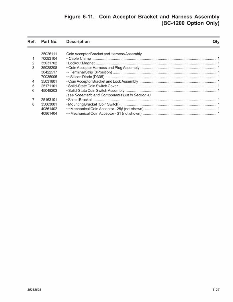
Figure 6-11. Coin Acceptor Bracket and Harness Assembly (BC-1200 Option Only)
Ref. Part No. Description Qty
35026111 Coin Acceptor Bracket and Harness Assembly1 70093104 • Cable Clamp ..................................................................................................................... 12 35031702 • Lockout Magnet ................................................................................................................. 13 35028208 • Coin Acceptor Harness and Plug Assembly ....................................................................... 1
30422517 • • Terminal Strip (3 Position) ................................................................................................. 170035005 • • Silicon Diode (D305) ........................................................................................................ 1
4 35031801 • Coin Acceptor Bracket and Lock Assembly ........................................................................ 15 25171101 • Solid-State Coin Switch Cover ........................................................................................... 16 45048203 • Solid-State Coin Switch Assembly ..................................................................................... 1
(see Schematic and Components List in Section 4)7 25163101 • Shield Bracket .................................................................................................................... 18 35063001 • Mounting Bracket (Coin Switch) .......................................................................................... 1
40861402 • • Mechanical Coin Acceptor - 25¢ (not shown) ................................................................... 140861404 • • Mechanical Coin Acceptor - $1 (not shown) ..................................................................... 1
6-28 25238802
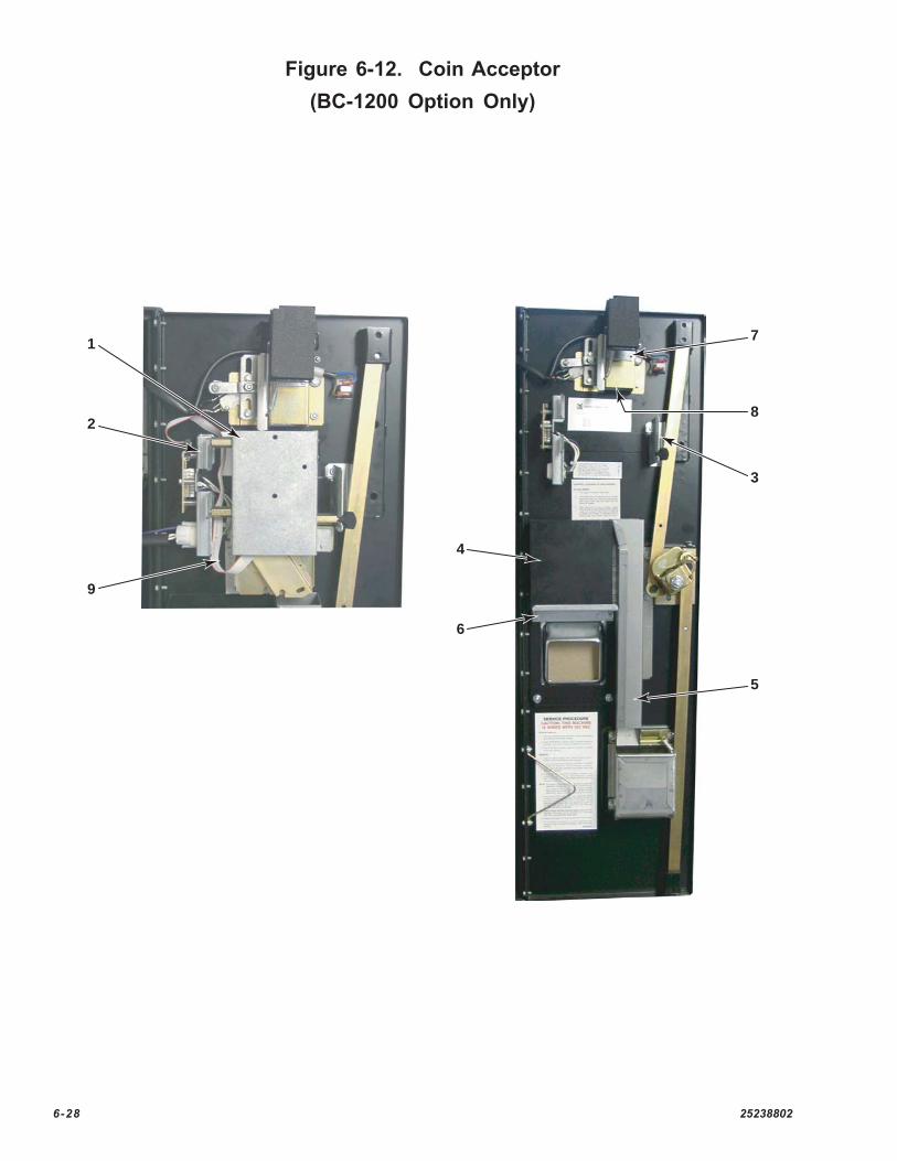
Figure 6-12. Coin Acceptor(BC-1200 Option Only)
4
6
7
8
3
5
2
1
9
25238802 6-29
Figure 6-12. Coin Acceptor (BC-1200 Option Only)
Ref. Part No. Description Qty
1 30998802 Holder/Adapter Assembly ..................................................................................................... 12 35175301 Mini-Acceptor Hinge Bracket .................................................................................................. 13 35175501 Mini-Acceptor Snap Bracket Assembly ................................................................................. 14 45050502 Cash Box ............................................................................................................................ 15 45086703 Slug Chute ........................................................................................................................... 16 35069201 Coin Box Bracket ................................................................................................................. 17 25172802 Coin Deflector ....................................................................................................................... 18 25169902 Bottom Chute - Coin Inlet ...................................................................................................... 19 35028216 Adapter Harness .................................................................................................................. 1
6-30 25238802
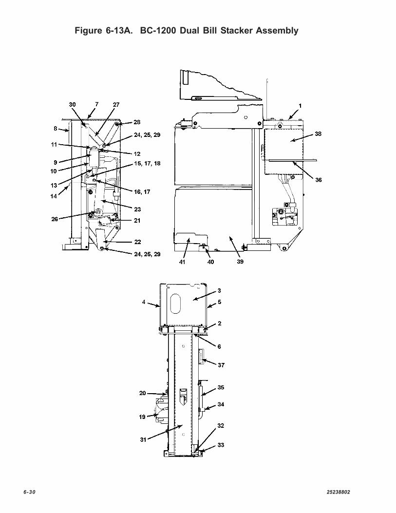
Figure 6-13A. BC-1200 Dual Bill Stacker Assembly
25238802 6-31
Figure 6-13A. BC-1200 Dual Bill Stacker Assembly
Ref. Part No. Description Qty
65046804 BC-1200 Dual Bill Stacker Assembly1 45052501 • Support Frame ........................................................................................................................................................ 12 25156911 • Shoulder Washer .................................................................................................................................................... 63 35072001 • Rear Hanger ............................................................................................................................................................ 14 35072101 • Front Hanger ........................................................................................................................................................... 15 45082202 • Front Hanger (RH) .................................................................................................................................................. 16 25178401 • Bill Box Catch ......................................................................................................................................................... 17 45052601 • Separator Chute Assembly ................................................................................................................................... 18 35072801 • Chute Edge ............................................................................................................................................................. 29 21150509 • Solenoid Assembly ................................................................................................................................................. 1
10 25178501 • Solenoid Bracket ..................................................................................................................................................... 111 25158001 • Stop Assembly ....................................................................................................................................................... 112 25098403 • Solenoid Stop Plate ................................................................................................................................................ 113 25178601 • Solenoid Plunger Assembly ................................................................................................................................... 114 25178701 • Bill Stop ................................................................................................................................................................... 115 25178801 • Bill Stop Pivot ......................................................................................................................................................... 116 21534705 • Pivot Pin .................................................................................................................................................................. 117 70143003 • External Retaining Ring .......................................................................................................................................... 418 70146003 • Bearing .................................................................................................................................................................. 1919 35072201 • Motor and Crank Assembly .................................................................................................................................... 1
45052901 • • Gear Motor ............................................................................................................................................................ 125179701 • • Crank and Pin Assembly ...................................................................................................................................... 170113204 • • Spiral Pin ............................................................................................................................................................... 1
20 35072301 • Motor Mounting Plate .............................................................................................................................................. 121 35099701 • Switch Assembly .................................................................................................................................................... 1
25179001 • • Switch Plate .......................................................................................................................................................... 121073102 • • Switch ................................................................................................................................................................... 121082901 • • Switch Actuator ..................................................................................................................................................... 121083001 • • Twin Nut ................................................................................................................................................................ 125054801 • • Insulator ................................................................................................................................................................. 1
22 35072401 • Drive Link ................................................................................................................................................................ 123 35072402 • Drive Link ................................................................................................................................................................ 124 70146004 • Bearing .................................................................................................................................................................... 225 70146010 • Bearing .................................................................................................................................................................... 226 70143004 • External Retaining Ring .......................................................................................................................................... 127 25179101 • Push Plate Link ....................................................................................................................................................... 4
70146003 • • Bearing ................................................................................................................................................................ 1628 25179202 • Support Shaft ......................................................................................................................................................... 2
70143003 • • External Retaining Ring ........................................................................................................................................ 829 21534706 • Pivot Pin .................................................................................................................................................................. 2
70143003 • • External Retaining Ring ........................................................................................................................................ 430 21534707 • Pivot Pin .................................................................................................................................................................. 2
70143003 • • External Retaining Ring ........................................................................................................................................ 431 35072501 • Push Plate ............................................................................................................................................................... 132 25179501 • Roller Shaft .............................................................................................................................................................. 133 25179601 • Roller ....................................................................................................................................................................... 2
70143003 • • External Retaining Ring ........................................................................................................................................ 634 70093401 • Cable Clamp .......................................................................................................................................................... 235 45052401 • Bill Stacker Harness Assembly .............................................................................................................................. 136 35077302 • Double Stacker Harness Assembly (6” long) ........................................................................................................ 137 65046701 • Driver Circuit Board Assembly
(see Schematics and Components List in Section 4)38 45052701 • Circuit Board Cover ................................................................................................................................................ 139 45034603 • Cash Box Assembly .............................................................................................................................................. 2
25096101 • • Foam Black ............................................................................................................................................................ 235039204 • • Pressure Plate Assembly ..................................................................................................................................... 2
40 45052801 • Lower Bill Box Mounting Bracket ........................................................................................................................... 141 25181801 • Lower Bill Box Stop an Stud Assembly ................................................................................................................ 1
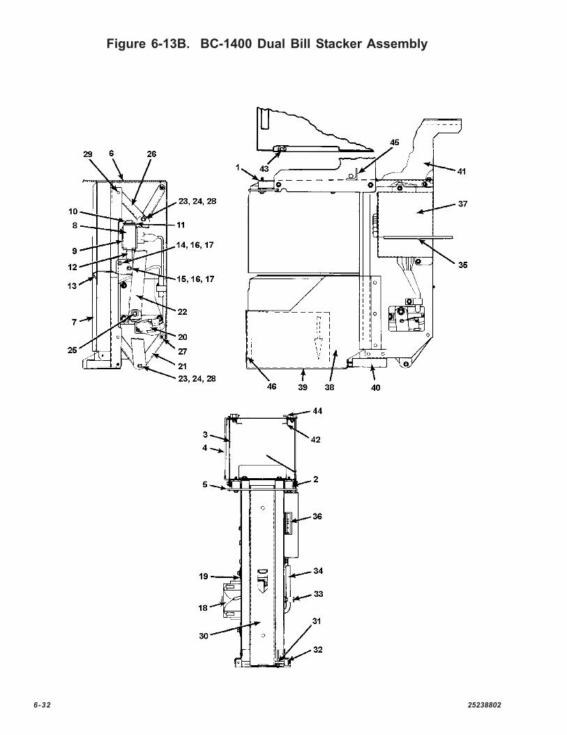
6-32 25238802
Figure 6-13B. BC-1400 Dual Bill Stacker Assembly
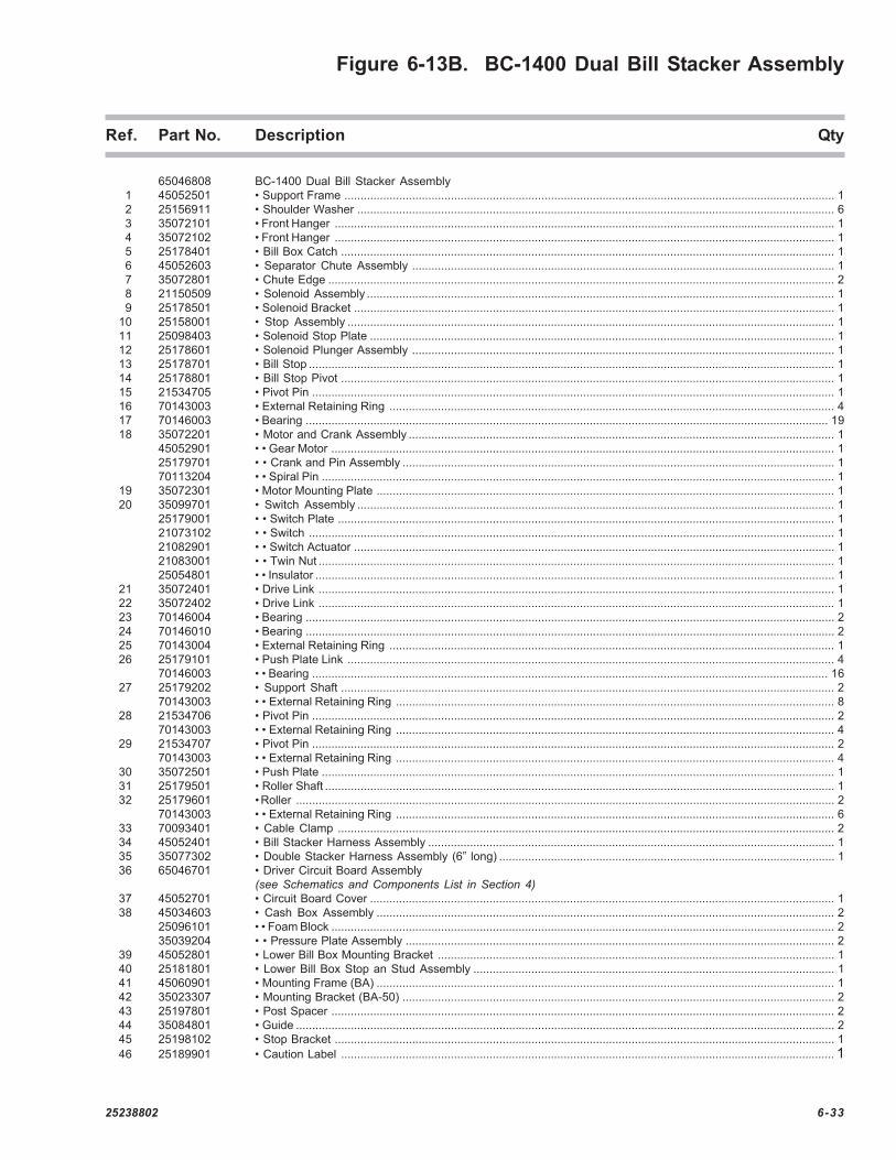
25238802 6-33
Figure 6-13B. BC-1400 Dual Bill Stacker Assembly
Ref. Part No. Description Qty
65046808 BC-1400 Dual Bill Stacker Assembly1 45052501 • Support Frame ........................................................................................................................................................ 12 25156911 • Shoulder Washer .................................................................................................................................................... 63 35072101 • Front Hanger ........................................................................................................................................................... 14 35072102 • Front Hanger ........................................................................................................................................................... 15 25178401 • Bill Box Catch ......................................................................................................................................................... 16 45052603 • Separator Chute Assembly ................................................................................................................................... 17 35072801 • Chute Edge ............................................................................................................................................................. 28 21150509 • Solenoid Assembly ................................................................................................................................................. 19 25178501 • Solenoid Bracket ..................................................................................................................................................... 1
10 25158001 • Stop Assembly ....................................................................................................................................................... 111 25098403 • Solenoid Stop Plate ................................................................................................................................................ 112 25178601 • Solenoid Plunger Assembly ................................................................................................................................... 113 25178701 • Bill Stop ................................................................................................................................................................... 114 25178801 • Bill Stop Pivot ......................................................................................................................................................... 115 21534705 • Pivot Pin .................................................................................................................................................................. 116 70143003 • External Retaining Ring .......................................................................................................................................... 417 70146003 • Bearing .................................................................................................................................................................. 1918 35072201 • Motor and Crank Assembly .................................................................................................................................... 1
45052901 • • Gear Motor ............................................................................................................................................................ 125179701 • • Crank and Pin Assembly ...................................................................................................................................... 170113204 • • Spiral Pin ............................................................................................................................................................... 1
19 35072301 • Motor Mounting Plate .............................................................................................................................................. 120 35099701 • Switch Assembly .................................................................................................................................................... 1
25179001 • • Switch Plate .......................................................................................................................................................... 121073102 • • Switch ................................................................................................................................................................... 121082901 • • Switch Actuator ..................................................................................................................................................... 121083001 • • Twin Nut ................................................................................................................................................................ 125054801 • • Insulator ................................................................................................................................................................. 1
21 35072401 • Drive Link ................................................................................................................................................................ 122 35072402 • Drive Link ................................................................................................................................................................ 123 70146004 • Bearing .................................................................................................................................................................... 224 70146010 • Bearing .................................................................................................................................................................... 225 70143004 • External Retaining Ring .......................................................................................................................................... 126 25179101 • Push Plate Link ....................................................................................................................................................... 4
70146003 • • Bearing ................................................................................................................................................................ 1627 25179202 • Support Shaft ......................................................................................................................................................... 2
70143003 • • External Retaining Ring ........................................................................................................................................ 828 21534706 • Pivot Pin .................................................................................................................................................................. 2
70143003 • • External Retaining Ring ........................................................................................................................................ 429 21534707 • Pivot Pin .................................................................................................................................................................. 2
70143003 • • External Retaining Ring ........................................................................................................................................ 430 35072501 • Push Plate ............................................................................................................................................................... 131 25179501 • Roller Shaft .............................................................................................................................................................. 132 25179601 • Roller ....................................................................................................................................................................... 2
70143003 • • External Retaining Ring ........................................................................................................................................ 633 70093401 • Cable Clamp .......................................................................................................................................................... 234 45052401 • Bill Stacker Harness Assembly .............................................................................................................................. 135 35077302 • Double Stacker Harness Assembly (6” long) ........................................................................................................ 136 65046701 • Driver Circuit Board Assembly
(see Schematics and Components List in Section 4)37 45052701 • Circuit Board Cover ................................................................................................................................................ 138 45034603 • Cash Box Assembly .............................................................................................................................................. 2
25096101 • • Foam Block ............................................................................................................................................................ 235039204 • • Pressure Plate Assembly ..................................................................................................................................... 2
39 45052801 • Lower Bill Box Mounting Bracket ........................................................................................................................... 140 25181801 • Lower Bill Box Stop an Stud Assembly ................................................................................................................ 141 45060901 • Mounting Frame (BA) .............................................................................................................................................. 142 35023307 • Mounting Bracket (BA-50) ...................................................................................................................................... 243 25197801 • Post Spacer ............................................................................................................................................................ 244 35084801 • Guide ....................................................................................................................................................................... 245 25198102 • Stop Bracket ........................................................................................................................................................... 146 25189901 • Caution Label ......................................................................................................................................................... 1

6-34 25238802
Figure 6-14. Money Return Lever Assembly
Ref. Part No. Description Qty
Ref. Money Return Lever Assembly1 21301801 • Cup Washer ..................................................................................................................... 22 25251203 • Pivot Link ........................................................................................................................... 13 27027206 • Coin Block Bracket (50¢/$1) ........................................................................................... A/R4 25255801 • Switch ............................................................................................................................... 15 70135512 • Palnut ................................................................................................................................ 26 70146008 • Nyliner Bearing ................................................................................................................... 27 70120703 • Plain Washer (Teflon) ......................................................................................................... 18 70143004 • External Retaining Ring ...................................................................................................... 19 21357811 • Elastic Stop Nut (#8-32) ..................................................................................................... 1
10 70093103 • Cable Clamp (1/4") ............................................................................................................ 111 25191301 • Indicator Light ..................................................................................................................... 112 35032009 • Empty Light Harness Assembly ......................................................................................... 1
Figure 6-14. Money Return Lever Assembly
2 9 6, 7, 8 5
10
11
1
34
12

25238802 6-35
DECALS
BC-1200 Only (from Figure 6-2)
Accepted Bill Decals
Door Color $1’s $1 & $5’s $1, $5, $10’s $1, $5, $10, $20’s
Black 35133702 35133703 35133704 35133705
Brown 35133712 35133713 35133714 35133715
Blue 35133707 35133708 35133709 35133710
Accepted Coin Decals
25211706 25¢ Decal
25211709 25¢/$1 Decal
25211710 $1 Decal
BC-1400 Only
Accepted Bill Decals
25239601 $10 Decal
25239602 $10 & $20 Decal
47002004 Label - “Pays $1 Coins”27029312 Decal - Service (BC-1400)27029313 Decal - Service (BC-2800)

6-36 25238802
ACCESSORY KITS
25223401 National Keyset Lock Cylinder & Key25223402 Van Lock Cylinder & Key25223403 Chicago Flexace Lock Cylinder & Key25223404 Abloy Lock Cylinder & Key25223405 Medeco Lock Cylinder & Key
27033503 Touch-Up Paint (White)27033504 Touch-Up Paint (Blue)27033505 Touch-Up Paint (Charcoal Brown)
REPAIR KITS
27025801 Bucket Solenoid Plunger Kit (Narrow Door)27025802 Bucket Solenoid Plunger Kit (Large Door)
27035901 Hopper Baffle Kit - High-Capacity (Quarters, Dimes, Nickels)27035902 Hopper Baffle Kit - High-Capacity ($1 Coins)27029902 Hopper Motor Brake Lever Assembly
27020302 Motor Armature Assembly (Multi-Products)27020801 Motor Armature Repair Kit (Molon)27023302 Motor Brake Pawl (Multi-Products)27023301 Motor Brake Pawl (Molon)37004601 Hopper Motor Gear Case Assembly (Heavy Duty)27033202 Hopper Conversion Kit (from small coins to large coins)
27034601 Door Guard Kit - high security frame that fits around the door openings
27031001 Line Filter Kit
27023902 Nylon Hopper Brush
65027609 S.B.A. Dollar Coin Hopper (or Large Tokens)67002606 Service Cabinet with Door and Lock
35027806 T-Handle Assembly (Chicago Lock)45062001 T-Handle Assembly (Medeco - w/Medeco Lock Cylinder)
35087512 Stellar Bank Kit - converts Standard Charcoal Brown Base & Filler Kit to Stellar Styling27037401 25¢ Coin Acceptor Kit
35087503 Bank Kit (includes Base & Top Filler) Blue35087504 Bank Kit (includes Base & Top Filler) White35087505 Bank Kit (includes Base & Top Filler) Black35087513 Bank Kit (includes Base & Top Filler) Charcoal Brown
35087533 Genesis Bank Kit - converts standard bank kit to Genesis Styling (should be used with35087505 Black Base & Filler Kit to match vending bank

25238802 6-37
35087403 Top Filler Kit Blue35087404 Top Filler Kit White35087405 Top Filler Kit Black
35087203 Base Kit Blue35087204 Base Kit White35087205 Base Kit Black
47000601 Coin and Chain Guide Assembly (Small Coins)47000602 Coin and Chain Guide Assembly (Large Coins)
REPAIR KITS (continued)