Embed Size (px)
Citation preview
Introductionwww.vishay.com Vishay Roederstein
Revision: 23-Nov-16 1 Document Number: 25001For technical questions, contact: [email protected]
THIS DOCUMENT IS SUBJECT TO CHANGE WITHOUT NOTICE. THE PRODUCTS DESCRIBED HEREIN AND THIS DOCUMENTARE SUBJECT TO SPECIFIC DISCLAIMERS, SET FORTH AT www.vishay.com/doc?91000
Introduction, Basic Concepts, and Definitions:Aluminum Capacitors, Vishay Roederstein
SYMBOLS AND TECHNICAL TERMSSYMBOLS DESCRIPTION
C Capacitance
CR Rated capacitance
U Voltage
UR Rated voltage
US Surge voltage
UB Working voltage, operating voltage
Urev Reverse voltage
I, I~, IAC Alternating current
IR Rated alternating current, ripple current
IL Leakage current
ILt Leakage current for acceptance test
ILB, IOP Operational leakage current
R Resistance
RESR; ESR Equivalent series resistance
Ris Insulation resistance
L Inductance
LESL, ESL Equivalent series inductance
tan Dissipation factor (tangent of loss angle)
Z Impedance
X Reactance
XC, ZC Capacitive reactance
XL, ZL Inductive reactance
T Temperature
Tamb Ambient temperature
Ts Surface temperature
T Difference of temperature, temperature rise
TUC Upper category temperature
TLC Lower category temperature
f Frequency
fr Resonance frequency
= 2 f Angular frequency
Fs Case surface area
Failure rate
L Lifetime multiplier
Introductionwww.vishay.com Vishay Roederstein
Revision: 23-Nov-16 2 Document Number: 25001For technical questions, contact: [email protected]
THIS DOCUMENT IS SUBJECT TO CHANGE WITHOUT NOTICE. THE PRODUCTS DESCRIBED HEREIN AND THIS DOCUMENTARE SUBJECT TO SPECIFIC DISCLAIMERS, SET FORTH AT www.vishay.com/doc?91000
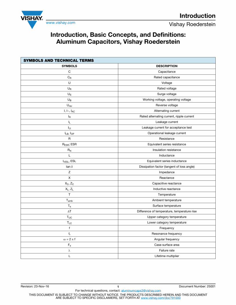
DESIGN AND POLARITYThe dielectric of an electrolytic capacitor with aluminum electrodes is made of aluminum oxide. One end of the dielectric sits firmly on an aluminum foil - the anode - while the other end sits on a liquid or solid electrolyte - the cathode. Power to the cathode is supplied via a second aluminum foil having a natural oxide layer as a dielectric with a blocking effect of just 1 V to 2 V. (Many years of use have resulted in wrongly describing this power supply foil as “cathode”). In its basic design the electrolytic capacitor is thus a direct current polarity-dependent capacitor (polarized style) with the positive pole being applied to the anode.
Apart from these so-called polarized electrolytic capacitors there are non-polarized capacitors available where the power supply foil is replaced by a second anode foil of the same type (non-polarized, bipolar style). This specific design allows operation with direct current of any polarity, as well as with pure alternating current.
Fig. 1 - Basic design of an electrolytic capacitor andequivalent circuit diagram
CLASSIFICATIONDepending on applications and requirements, electrolytic capacitors are classified as:
a) Long-life grade (LL)Electrolytic capacitors designed for increased requirements.
b) General-purpose grade (GP)Electrolytic capacitors designed for general requirements.
Furthermore, all capacitor types have been subdivided by their application classes according to DIN 40040.
STORAGE LIFEDuring transport or storage, the temperature of electrolytic capacitors is allowed to fall below their lower category temperature and reach a minimum of -65 °C, while their upper category temperature may not be exceeded.
Depending on the design and the purity of the materials used, electrolytic capacitors offer very good storage properties. They can be stored in dry rooms at temperature ranging from -40 °C to +40 °C (preferably between 0 °C and +25 °C) for up to three years without any restriction. Within that period it is possible to apply the fully-rated voltage to the capacitors without any further preparation. This procedure neither impairs the capacitor’s operational reliability nor its life expectancy.
All electrolytic capacitors have a leakage current when a direct current is applied. This leakage current depends on time, voltage, and temperature. After long dead storage this leakage current will increase and, for a short time, can be 10 times greater at the time of reuse. The capacitor will not be damaged and its life expectancy will not be impaired if the rated voltage is applied directly after long storage. In general, the expected continuous operating leakage current will be re-attained or fall below its value after about 30 minutes. Any operation below the rated voltage will result in a significantly lower leakage current.
ELECTRICAL PARAMETERS
Rated Voltage UR and Operating Voltage UB
The rated voltage is defined as the voltage for which the capacitor has been designed and after which it is designated. The operating voltage may be smaller, but may never exceed the rated voltage value. A reduction in the operating voltage will not significantly increase the capacitor’s lifetime. The capacitors may be charged with the specified rated direct voltage in the specified operating temperature range. In case of ripple alternating voltage, the peak voltage value must not exceed the rated value.
Cathode
Electrolyte
Electrolyte paper(spacer)
Dielectric layer
Anode
Aluminum foil(highly etched)
Power supplyfoil
Aluminum foil,etched
Al2O3(natural oxide layer)
Al2O3(electrochemical oxide
layer (forming)
Ris
RESR LESLC
+ -
C = Capacitance of the oxide layerRis = Oxide layer insulation resistanceRESR = Equivalent series resistanceLESL = Equivalent series inductance
Introductionwww.vishay.com Vishay Roederstein
Revision: 23-Nov-16 3 Document Number: 25001For technical questions, contact: [email protected]
THIS DOCUMENT IS SUBJECT TO CHANGE WITHOUT NOTICE. THE PRODUCTS DESCRIBED HEREIN AND THIS DOCUMENTARE SUBJECT TO SPECIFIC DISCLAIMERS, SET FORTH AT www.vishay.com/doc?91000
Surge Voltage US
The surge voltage is defined as the maximum voltage which may be applied to the capacitor for a short time only (in one hour a maximum of five times with a duration of one minute each.) The surge voltage may not be used for periodic charge and discharge.
US = 1.15 x UR for UR 250 V
US = 1.10 x UR for UR > 250 V
Ripple Alternating Voltage
The ripple voltage is defined as the effective value alternating voltage with which the capacitor may be charged in addition to direct voltage. The peak value of resulting ripple DC voltage must not exceed the rated voltage value. A reverse polarity voltage with a peak value of > 1.5 V must not occur.
Reverse Voltage Urev
A reverse polarity of up to 1.5 V is permissible.
CAPACITANCE
Rated Capacitance CR
The rated capacitance is defined as the capacitance value, after which the capacitor has been designated. The capacitance value may vary within the permissible tolerance limits.
Alternating Voltage Capacitance CW
The AC capacitance normally corresponds to the rated capacitance value. It is determined by measuring the AC resistance at an AC voltage of 0.5 V. Since AC capacitance depends on frequency and temperature, a specific measuring frequency and temperature have to be agreed upon. IEC 60384-4 stipulates a frequency of 100 Hz and a temperature of 20 °C.
Direct Voltage Capacitance CDC
The DC capacitance is determined from the quantity of charge which is stored after a DC voltage charging of the capacitor. The measurement is effected during a single discharge under specified conditions. The measuring procedures are described in DIN 41 328. If both values, C and CDC, are measured at an electrolytic capacitor, the result will always be: C < CDC.Depending on the design CDC (1.05...1.30) x C.
Temperature Dependence of AC Capacitance
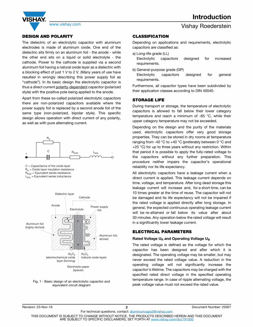
The measured AC capacitance decreases with falling temperatures. Falling temperatures result in an increased viscosity of electrolyte and thus in an increasing ohmic resistance. In fact, a model calculation shows that the total capacitance of capacitive surface elements which are parallel connected via different series resistors R1, R2, etc. will decrease, if the series resistors increase. Usually this behavior is described as follows: “High-resistive coupled surface elements have a lower capacitive effect.”
Fig. 2 - Detail from an equivalent circuit diagram fortwo surface elements
Fig. 3 - Typical temperature dependentbehavior of AC capacitance
Frequency Dependence of AC Capacitance
The frequency dependence of AC capacitance is similar to its temperature dependence. The capacitive partial resistance ZCi decreases with increasing frequency f. At the same time the influence of the ohmic partial resistance Ri of the AC resistance Zi is increasing. In this case, too, “high-resistive coupled surface elements have a lower capacitive effect”.
EQUIVALENT SERIES RESISTANCE RESR
The equivalent series resistance is defined as the ohmic part of the AC resistance describing the losses occurring in an electrolytic capacitor. It consists of three partial resistance values: the lead and the foil resistance, the electrolyte paper resistance, and the oxide layer resistance. Just as any other ohmic resistance, RESR is temperature-dependent, too. Moreover, it contains a frequency-dependent part - the oxide layer resistance. RESR is usually calculated from the dissipation factor tan as follows:
RESR []C [F]f [Hz]
In practical operation the lower limit of the RESR is given by the ohmic part of the contact points and the foil resistance values. Thus it will not always be possible to achieve calculated values below 0.03 .
The foil resistance and RESR can further be reduced by using the multiple tab technique. This technique consists of
- 20 0 20 40 60 80- 400.6
0.7
0.8
0.9
1.0100 V40 V16 V
6.3 V
[°C]
CC
20 °
C
1.1
1.2
RESRtan
C------------
tan2 x x f x C----------------------------------= =
Introductionwww.vishay.com Vishay Roederstein
Revision: 23-Nov-16 4 Document Number: 25001For technical questions, contact: [email protected]
THIS DOCUMENT IS SUBJECT TO CHANGE WITHOUT NOTICE. THE PRODUCTS DESCRIBED HEREIN AND THIS DOCUMENTARE SUBJECT TO SPECIFIC DISCLAIMERS, SET FORTH AT www.vishay.com/doc?91000
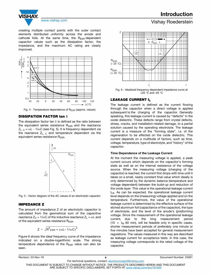
creating multiple contact points with the outer contact elements distributed uniformly across the anode and cathode foils. At the same time, the RESR-dependent capacitor values such as the dissipation factor, the impedance, and the maximum AC rating are clearly improved.
Fig. 4 - Temperature dependence of RESR (approx. values)
DISSIPATION FACTOR tan The dissipation factor tan is defined as the ratio between the equivalent series resistance RESR and the reactance ZL, C = L - 1/C (see Fig. 5). It is frequency-dependent via the reactance ZL, C and temperature dependent via the equivalent series resistance RESR.
Fig. 5 - Vector diagram of the AC values of an electrolytic capacitor
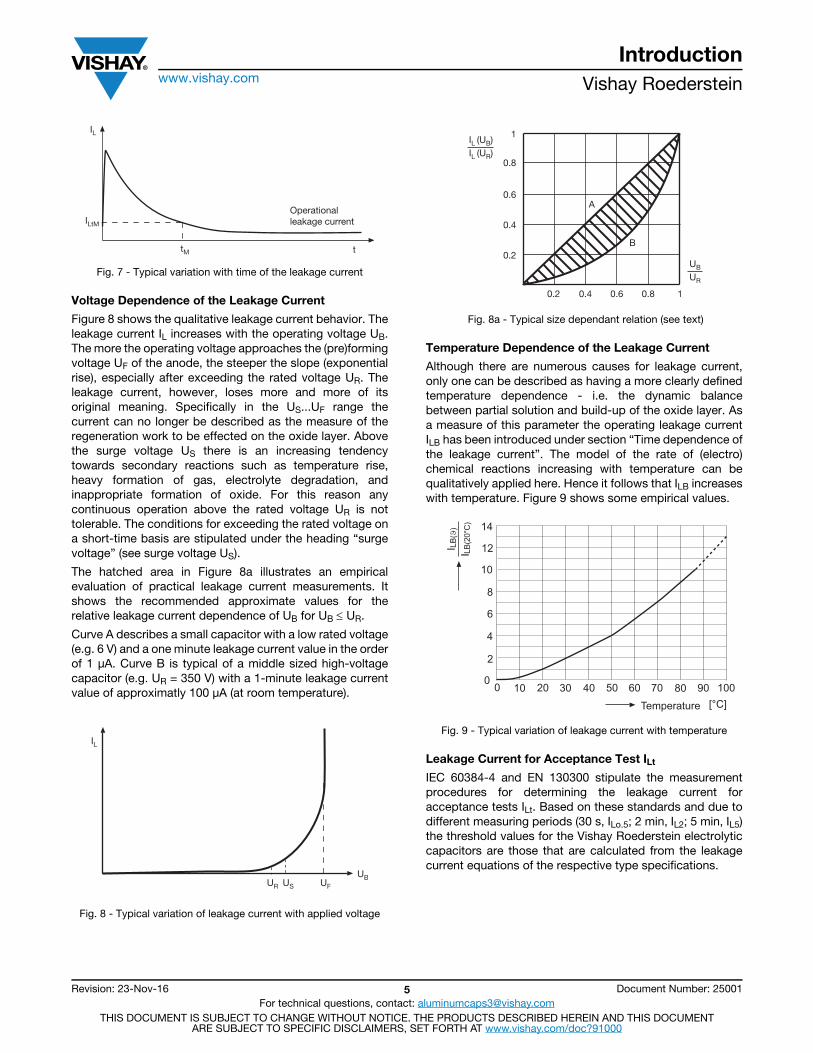
IMPEDANCE ZThe amount of impedance Z of an electrolytic capacitor is calculated from the geometrical sum of the capacitive reactance ZC = 1/C of the inductive reactance ZL = L and of the equivalent series resistance RESR.
Figure 6 shows the ideal frequency curve of the impedance indicated on a double-logarithmic scale. The strong temperature dependence of the RESR value can also be seen.
Fig. 6 - Idealized frequency dependent impedance curve at+25 °C and -25 °C
LEAKAGE CURRENT ILThe leakage current is defined as the current flowing through the capacitor when a direct voltage is applied subsequent to the charging of the capacitor. Generally speaking, this leakage current is caused by “defects” in the oxide dielectric. These defects range from crystal defects, stress, cracks, and installation-related damage, to a partial solution caused by the operating electrolyte. The leakage current is a measure of the “forming state”, i.e. of the regeneration to be effected on the oxide dielectric. This current depends on a multitude of factors, such as time, voltage, temperature, type of electrolyte, and “history” of the capacitor.
Time Dependence of the Leakage Current
At the moment the measuring voltage is applied, a peak current occurs which depends on the capacitor’s forming state as well as on the internal resistance of the voltage source. When the measuring voltage (charging of the capacitor) is reached, the current first drops with time until it takes on a small, nearly constant final value which ideally is only determined by the dynamic balance (temperature and voltage dependent) between the build-up and reduction of the oxide layer. This value is the operational leakage current ILB. As can be expected, the operational leakage current level depends on the (measuring) voltage applied and on the temperature. Furthermore, the value of the operational leakage current is determined by the effective surface of the etched aluminum foil (capacitance of the capacitor), the type of electrolyte, and the level of the anode’s (pre)forming voltage. Since the measurement of the operational leakage current, due to the long measurement period (10 < tM 60 min), will be feasible only in specific cases, shorter measurement periods of preferably one minute or five minutes have been accepted for general measurement regulations. The values measured in this way are described as leakage current for acceptance tests. In this case, the measuring voltage corresponds to the rated voltage of the capacitor.
40 20 0 20 40 60 80 100 1200.5
1
23
5
23
5
10
6.3 V
25 V
100 V
[°C]
ES
RE
SR
20 °
C
RESR
ωL
1ωC
Z R2ESR + L- 1/C 2=
RESR(- 25 °C)
RESRC L
ffr
ωLωC1
RESR(+ 25 °C)
Z
Introductionwww.vishay.com Vishay Roederstein
Revision: 23-Nov-16 5 Document Number: 25001For technical questions, contact: [email protected]
THIS DOCUMENT IS SUBJECT TO CHANGE WITHOUT NOTICE. THE PRODUCTS DESCRIBED HEREIN AND THIS DOCUMENTARE SUBJECT TO SPECIFIC DISCLAIMERS, SET FORTH AT www.vishay.com/doc?91000
Fig. 7 - Typical variation with time of the leakage current
Voltage Dependence of the Leakage Current
Figure 8 shows the qualitative leakage current behavior. The leakage current IL increases with the operating voltage UB. The more the operating voltage approaches the (pre)forming voltage UF of the anode, the steeper the slope (exponential rise), especially after exceeding the rated voltage UR. The leakage current, however, loses more and more of its original meaning. Specifically in the US...UF range the current can no longer be described as the measure of the regeneration work to be effected on the oxide layer. Above the surge voltage US there is an increasing tendency towards secondary reactions such as temperature rise, heavy formation of gas, electrolyte degradation, and inappropriate formation of oxide. For this reason any continuous operation above the rated voltage UR is not tolerable. The conditions for exceeding the rated voltage on a short-time basis are stipulated under the heading “surge voltage” (see surge voltage US).
The hatched area in Figure 8a illustrates an empirical evaluation of practical leakage current measurements. It shows the recommended approximate values for the relative leakage current dependence of UB for UB UR.
Curve A describes a small capacitor with a low rated voltage (e.g. 6 V) and a one minute leakage current value in the order of 1 μA. Curve B is typical of a middle sized high-voltage capacitor (e.g. UR = 350 V) with a 1-minute leakage current value of approximatly 100 μA (at room temperature).
Fig. 8 - Typical variation of leakage current with applied voltage
Fig. 8a - Typical size dependant relation (see text)
Temperature Dependence of the Leakage Current
Although there are numerous causes for leakage current, only one can be described as having a more clearly defined temperature dependence - i.e. the dynamic balance between partial solution and build-up of the oxide layer. As a measure of this parameter the operating leakage current ILB has been introduced under section “Time dependence of the leakage current”. The model of the rate of (electro) chemical reactions increasing with temperature can be qualitatively applied here. Hence it follows that ILB increases with temperature. Figure 9 shows some empirical values.
Fig. 9 - Typical variation of leakage current with temperature
Leakage Current for Acceptance Test ILt
IEC 60384-4 and EN 130300 stipulate the measurement procedures for determining the leakage current for acceptance tests ILt. Based on these standards and due to different measuring periods (30 s, ILo.5; 2 min, IL2; 5 min, IL5) the threshold values for the Vishay Roederstein electrolytic capacitors are those that are calculated from the leakage current equations of the respective type specifications.
Operationalleakage current
ttM
IL
ILtM
UR
IL
US UF
UB
UB
UR
IL (UB)IL (UR)
1
B
A
0.80.60.40.2
0.2
0.4
0.6
0.8
1
��
��������� �� �
�� ��
����
�
� ��
���
�
�
��
��
��
�
�
�� �� �� �� �� �� ���������
Introductionwww.vishay.com Vishay Roederstein
Revision: 23-Nov-16 6 Document Number: 25001For technical questions, contact: [email protected]
THIS DOCUMENT IS SUBJECT TO CHANGE WITHOUT NOTICE. THE PRODUCTS DESCRIBED HEREIN AND THIS DOCUMENTARE SUBJECT TO SPECIFIC DISCLAIMERS, SET FORTH AT www.vishay.com/doc?91000
ALTERNATING CURRENTThe alternating current is defined as the effective value of the alternating current with which the capacitor is charged.
Rated Alternating Current IR
The permissible rated alternating current is defined in such a way that at an upper category temperature TUC and at a frequency of 100 Hz (measuring frequency of capacitance and dissipation factor), the temperature of the case surface area rises by 3 K. The resulting AC values IR are indicated in the datasheets for each capacitor.
Maximum Permissible Alternating Current I, AC Rating
The maximum permissible alternating current rating depends on ambient temperature Tamb' case surface area Fs' equivalent series resistance RESR (or the dissipation factor tan ), as well as on excess surface temperature T (temperature rise, difference between surface temperature Ts and ambient temperature Tamb). The permissible temperature rise T is specified by the respective manufacturer. For Vishay Roederstein electrolytic capacitors this value is based on IEC 60384-4 and is 3 K in relation to the upper category temperature TUC. Due to the temperature and frequency dependence of the equivalent series resistance RESR (or the dissipation factor tan ) the maximum permissible alternating current is also dependent on the alternating current frequency f. Since the life expectancy of an electrolytic capacitor is considerably determined by its thermal load (permutation model, see section Lifetime), the temperature rise caused by an AC load presents a significant factor of the capacitor's lifetime. The individual lifetime tables show the interrelation between the maximum permissible alternating current I, the ambient temperature Tamb' the surface temperature Ts' the alternating current frequency f, as well as the lifetime. (Sections Standard Lifetime Conversion Table and Type Specific Lifetime Conversion Table explain the use of these tables.)
ELECTRICAL STRENGTH OF THE INSULATION The insulating sleeve can withstand a voltage of at least 1000 V.
INSULATION RESISTANCE OF THE INSULATIONThe insulation resistance of the sleeve material is a minimum of 100 M.
CLIMATIC CONDITIONSFor reasons of reliability and due to the temperature dependence of electrical parameters certain limits have to be observed for the climatic conditions. The upper and lower category temperature are considered important climatic conditions for electrolytic capacitors. Furthermore the degree of humidity has to be taken into account. These three values are indicated in coded form in the applicability class and lEG climatic category (see section Climatic and Applicability Categories).
Upper Category Temperature TUC
The use of electrolytic capacitors is subject to specific upper temperature limits. Exceeding these limits may result in early failure of the capacitor. To avoid this, upper category temperatures are fixed which indicate the maximum permissible ambient temperature of the capacitor for continuous operation. The upper category temperature is given with the temperature range value in the datasheets. Sections Maximum Permissible Alternating Current I, AC Rating and Lifetime have shown that the electrolytic capacitor's lifetime and reliability depend considerably on the capacitor's temperature. This is why Vishay recommend using the capacitor at the lowest temperature possible to increase lifetime and reliability. Furthermore, Vishay recommend mounting the electrolytic capacitors inside the units at positions having a low ambient temperature.
Lower Category Temperature TLC
Due to an impaired electrolytic conductivity, a decreasing temperature results in higher values for impedance and dissipation factor (or RESR values). Most capacitor applications limit such an increase to specific threshold values. For this reason it is practical to stipulate a lower category temperature which is also indicated in the temperature range value given in the datasheet. It should be emphasized, however, that an operation below the specified lower category temperature is possible without damaging the capacitor. This is particularly true if the capacitor is exposed to an alternating-current load. Compared to the lower ambient temperature, the alternating current flowing through the increased equivalent series resistance can heat the electrolytic capacitor to such an extent, that its properties still ensure proper functioning of the unit.
Climatic and Applicability Categories
According to DIN 40040 the applicability class is given in form of a three-letter code. The IEC publication indicates a so-called Category (IEC Climatic Category). The datasheets list both specifications. The first letter in the DIN 40040 formula stands for the lower category temperature, the second for the upper category temperature, and the third for the permissible humidity.
Note(1) Rare and mild formation of dew permissible
DIN CLIMATIC CATEGORY1st letter lower category temperature
F -55 °C
G -40 °C
H -25 °C
2nd letter upper category temperature
K 125 °C
M 100 °C(105 °C)
P 85 °C
S 70 °C
3rd letter relative humidity/ annual average30 days/year max. occasional formation of dew permissible
C 95 % 100 % 100 %
yes
D 80 % 100 % 90 %
yes
E 75 %95 % 85 %
yes (1)
F 75 %95 % 85 %
yes
56 days damp heat (tested according to IEC 60068-1)
40 / 085 / 56
Upper category temperature 85 °CLower category temperature - 40 °C
Introductionwww.vishay.com Vishay Roederstein
Revision: 23-Nov-16 7 Document Number: 25001For technical questions, contact: [email protected]
THIS DOCUMENT IS SUBJECT TO CHANGE WITHOUT NOTICE. THE PRODUCTS DESCRIBED HEREIN AND THIS DOCUMENTARE SUBJECT TO SPECIFIC DISCLAIMERS, SET FORTH AT www.vishay.com/doc?91000
HOW TO USE ELECTROLYTIC CAPACITORS
Date of Manufacture (Code) IEC 60062
The month and the year of manufacture are indicated. The year is given first, followed by the month.
Example: 2007 May: V5
Alternatively it is possible to indicate the year and the week. In this case the first two figures indicate the year and the last two the week.
Example: 2003, 20th week: 0320
Pulse Handling
Vishay Roederstein electrolytic capacitors exhibit good pulse handling characteristics. However, due to continuously increased surface gain of anode foils, absolute compliance with the IEC requirement
cannot be guaranteed without taking specific measures, which need prior agreement.
Vibration Resistance
If not otherwise indicated in the datasheets, the lEC publication 60068-2 is applicable: Test FC at 5 g; stress period: 1.5 h; frequency 10 Hz to 55 Hz, maximum displacement 0.35 mm.
Mounting Position
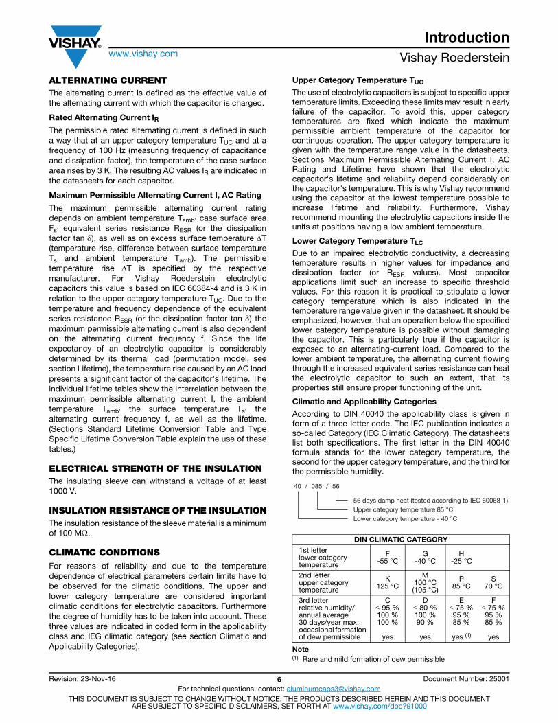
Care should be taken when mounting capacitors which have a pressure release valve. In vertical mounting the valve should always be at the top to avoid electrolytic leakage if the pressure valve is triggered. Similarly, when mounting the capacitor in a horizontal position the pressure valve should be in the “12- o’clock position”.
Fig. 10 - Recommended mounting position
We recommend not to have PC-board traces below radial aluminum electrolytic capacitors.
Low and High Pressure
Vishay Roederstein electrolytic capacitors may be used at any low pressure and at any altitude. The operating temperature should not fall below the lower category temperature. The capacitors may not be used at pressures exceeding 120 kPa.
Cleaning, Moulding
Halogenated hydrocarbons, particularly CFCs (chlorofluorocarbons), are frequently used for the cleaning of boards. There are for instance several FREON types (registered trademark of Du Pont) based on 1,1,1- Trichlorotrifluoroethane.
The manufacturers of aluminum electrolytic capacitors warn against the use of these solvents since a corrosive effect on aluminium is definitely possible. This corrosive mechanism, which may be triggered by the external influence of compounds containing CFCs, is very complex and can lead to consequential changes. Only the strict compliance with a number of clearly defined conditions can provide any protection against the penetration of solvents. We do not consider it necessary to list the conditions here but would advise you against using halogenated compounds for cleaning. Moreover, you should check whether the plastic insulation is resistant to the detergent you want to use. Ketone type solvents (e.g. acetone, methyl ethyl ketone) and ester type solvents (e.g. ethyl acetate, butyl acetate) should preferably not be used or only after checking their effect in the cleaning process. The same applies to aromatic hydrocarbons (e.g. xylenes) and aliphatic hydrocarbons (e.g. petroleum ether).
We recommend using water-based or alcohol-based detergents (e.g. ethanol, isopropanol, isobutyl alcohol, various ethylene glycols, etc.). We also recommend continuous monitoring of the cleaning bath in order to avoid the accumulation of corrosive agents (e.g. chlorides from solder residues, possibly sulphonates from surface active agents). Careful drying should immediately follow cleaning.
Similar procedures should be observed when electrolytic capacitors are varnished or moulded. Care must be taken that any varnish or moulding components such as resin, hardener, accelerator, thinner, filler, coloring matter, etc. do not contain any halogen.
CODE (YEAR) CODE (MONTH)
2009 X January 1
2010 A February 2
2011 B March 3
2012 C April 4
2013 D May 5
2014 E June 6
2015 F July 7
2016 H August 8
2017 J September 9
2018 K October 0
2019 L November N
2020 M December D
CC
-------- ± 10 % after 106 switching cycles
Saftey vent
90°
Introductionwww.vishay.com Vishay Roederstein
Revision: 23-Nov-16 8 Document Number: 25001For technical questions, contact: [email protected]
THIS DOCUMENT IS SUBJECT TO CHANGE WITHOUT NOTICE. THE PRODUCTS DESCRIBED HEREIN AND THIS DOCUMENTARE SUBJECT TO SPECIFIC DISCLAIMERS, SET FORTH AT www.vishay.com/doc?91000
ELECTROLYTEThe operating electrolyte is an electrically conductive liquid. Its composition differs according to type and voltage range. A polar organic liquid of a high boiling point with a certain amount of salt provides its ionic conductivity. Halogenated hydrocarbons are not used. Water may occur as a constituent of the electrolyte. The salts used can be organic or inorganic.The electrolytes can be mixed with water. Since they have an almost neutral pH value, there will be no acidic or caustic reaction. Its flash point is always above 80 °C. They do not contain any easily or highly ignitable agents and no explosive substances.Great attention is given to selecting only those electrolytic constituents that combine the least possible toxicity with the utmost environmental compatibility. Unfortunately the present state of technological development does not always enable us to fully avoid the use of substances which are considered harmful. However, we do not use highly toxic, carcinogenic, or questionable compounds. Extreme care should be taken when handling electrolytic liquid that has leaked out.- Avoid skin contact- Do not inhale vapors- Provide sufficient ventilationIf the electrolyte has come into contact with your skin, mucous membrane, or eyes, immediately rinse carefully for several minutes under running water. Remove affected clothing. Seek medical attention if you have swallowed any liquid.We would like to remind you that the following errors will trigger the safety mechanism and may result in a discharge of electrolytic fluid:- Reverse polarity- Excessive voltage- Excessive current load- Overheating
DISPOSAL OF USED ALUMINUM ELECTROLYTIC CAPACITORSDue to potential harmful effects to the environment, special regulations have to be observed which dictate the disposal of capacitors as toxic waste.
Important remarks:The aluminum electrolytic capacitors do not contain any polychlorinated biphenyls (PCB) or similar substances that may produce dioxins when burning. Moreover, during manufacture we do not use any substances that may harm the ozone layer.
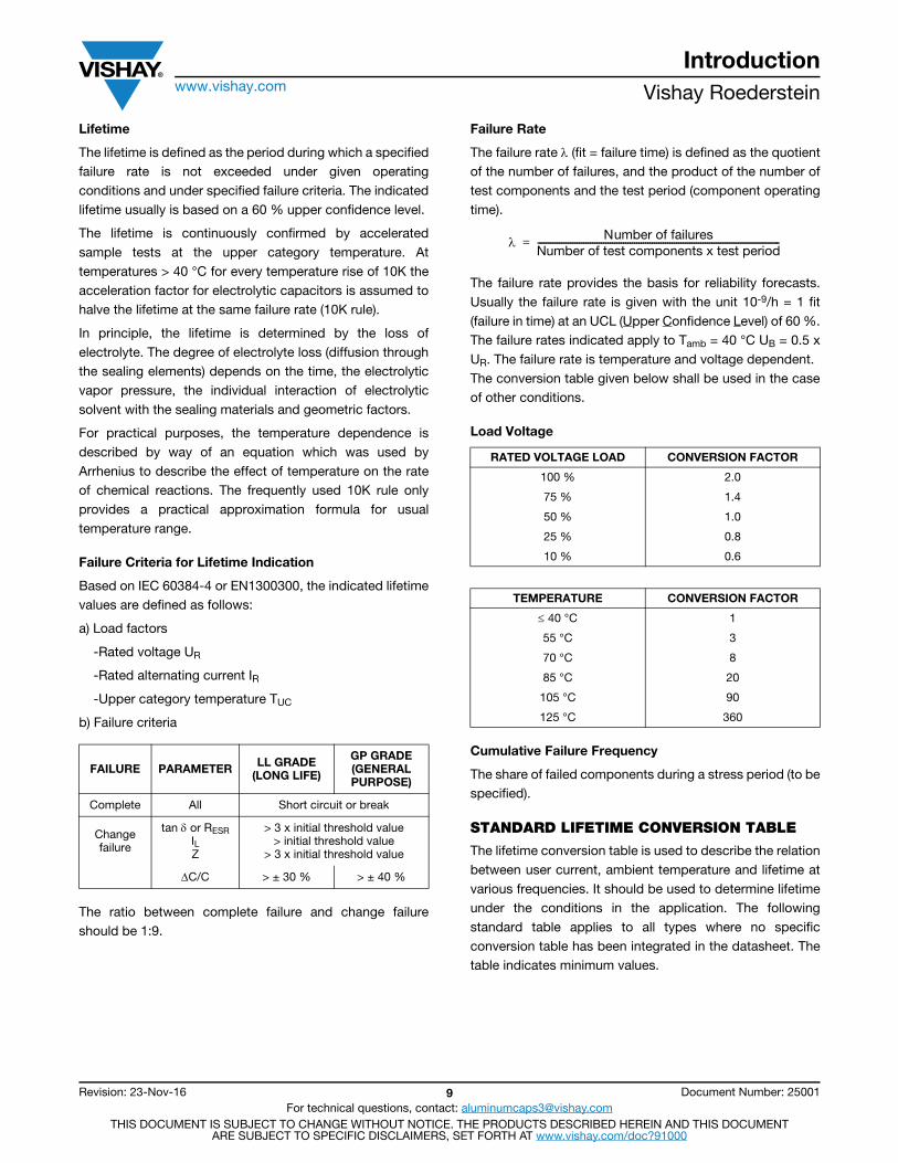
OPERATIONAL RELIABILITYThe specifications regarding the reliability of electrolytic capacitors refer to:1) The failure rate during operation2) The beginning of wear-out failures (end of lifetime)
Fig. 11 - Failure rate () as a function of time (“bath-tub life curve”)
Early failures (region a) of electrolytic capacitors occur during the manufacturing process and are eliminated. We normally expect a constant low failure rate () during the stated lifetime of capacitors (region b). Subsequently the electrolytic capacitors will tend to suffer failures due to drying out (region c).
Endurance TestIEC 60384-4 and EN 130300 define the criteria for permissible changes in the values of electrical parameters following endurance tests at rated voltage and upper category temperature. The duration and the conditions for the specific capacitor types are given in the respective separate specifications. The endurance test does not allow any direct assessment of the lifetime of an electrolytic capacitor. Therefore the duration of the test must not be confused with the indicated lifetime of the respective capacitor type.If one of the following conditions is not met, the capacitor has failed the test.
Region ofwear-out failures
lifetime
b causer
failurerate manufacture
timeRegion withconstant failure rate
Early failureregion
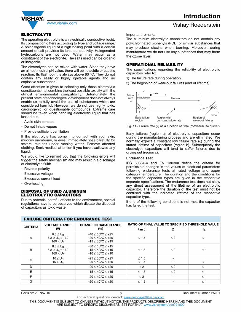
FAILURE CRITERIA FOR ENDURANCE TEST
CRITERIA VOLTAGE RANGE(V)
CHANGE IN CAPACITANCE(%)
RATIO OF FINAL VALUE TO SPECIFIED THRESHOLD VALUE
tan Z IL
A6.3 UR
6.3 < UR 160160 < UR
-40 C/C +25-30 C/C +30-15 C/C +15
1.5 3 1
B6.3 UR
6.3 < UR 160 160 < UR
-30 C/C +15-15 C/C +15-10 C/C +10
1.3 2 1
C 16 UR16 > UR
-25 C/C +25-20 C/C +20
1.5 1.5
-- 1
D -20 C/C +20 2 2 1
E -15 C/C +15 1.5 2 1
F -20 C/C +20 2 - 1
G -20 C/C +20 1.5 - 1
Introductionwww.vishay.com Vishay Roederstein
Revision: 23-Nov-16 9 Document Number: 25001For technical questions, contact: [email protected]
THIS DOCUMENT IS SUBJECT TO CHANGE WITHOUT NOTICE. THE PRODUCTS DESCRIBED HEREIN AND THIS DOCUMENTARE SUBJECT TO SPECIFIC DISCLAIMERS, SET FORTH AT www.vishay.com/doc?91000
Lifetime
The lifetime is defined as the period during which a specified failure rate is not exceeded under given operating conditions and under specified failure criteria. The indicated lifetime usually is based on a 60 % upper confidence level.
The lifetime is continuously confirmed by accelerated sample tests at the upper category temperature. At temperatures > 40 °C for every temperature rise of 10K the acceleration factor for electrolytic capacitors is assumed to halve the lifetime at the same failure rate (10K rule).
In principle, the lifetime is determined by the loss of electrolyte. The degree of electrolyte loss (diffusion through the sealing elements) depends on the time, the electrolytic vapor pressure, the individual interaction of electrolytic solvent with the sealing materials and geometric factors.
For practical purposes, the temperature dependence is described by way of an equation which was used by Arrhenius to describe the effect of temperature on the rate of chemical reactions. The frequently used 10K rule only provides a practical approximation formula for usual temperature range.
Failure Criteria for Lifetime Indication
Based on IEC 60384-4 or EN1300300, the indicated lifetime values are defined as follows:
a) Load factors
-Rated voltage UR
-Rated alternating current IR
-Upper category temperature TUC
b) Failure criteria
The ratio between complete failure and change failure should be 1:9.
Failure Rate
The failure rate (fit = failure time) is defined as the quotient of the number of failures, and the product of the number of test components and the test period (component operating time).
The failure rate provides the basis for reliability forecasts. Usually the failure rate is given with the unit 10-9/h = 1 fit (failure in time) at an UCL (Upper Confidence Level) of 60 %. The failure rates indicated apply to Tamb = 40 °C UB = 0.5 x UR. The failure rate is temperature and voltage dependent. The conversion table given below shall be used in the case of other conditions.
Load Voltage
Cumulative Failure Frequency
The share of failed components during a stress period (to be specified).
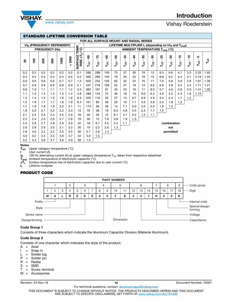
STANDARD LIFETIME CONVERSION TABLE
The lifetime conversion table is used to describe the relation between user current, ambient temperature and lifetime at various frequencies. It should be used to determine lifetime under the conditions in the application. The following standard table applies to all types where no specific conversion table has been integrated in the datasheet. The table indicates minimum values.
FAILURE PARAMETER LL GRADE(LONG LIFE)
GP GRADE(GENERALPURPOSE)
Complete All Short circuit or break
Change failure
tan or RESRILZ
> 3 x initial threshold value> initial threshold value
> 3 x initial threshold value
C/C > ± 30 % > ± 40 %
RATED VOLTAGE LOAD CONVERSION FACTOR
100 % 2.0
75 % 1.4
50 % 1.0
25 % 0.8
10 % 0.6
TEMPERATURE CONVERSION FACTOR
40 °C 1
55 °C 3
70 °C 8
85 °C 20
105 °C 90
125 °C 360
Number of failuresNumber of test components x test period--------------------------------------------------------------------------------------------------------------=
Introductionwww.vishay.com Vishay Roederstein
Revision: 23-Nov-16 10 Document Number: 25001For technical questions, contact: [email protected]
THIS DOCUMENT IS SUBJECT TO CHANGE WITHOUT NOTICE. THE PRODUCTS DESCRIBED HEREIN AND THIS DOCUMENTARE SUBJECT TO SPECIFIC DISCLAIMERS, SET FORTH AT www.vishay.com/doc?91000
NotesTUC Upper category temperature (°C)I User current (A)IR 100 Hz alternating current (A) at upper category temperature TUC taken from respective datasheetTamb Ambient temperature of electrolytic capacitor (°C)Ts Surface temperature rise of electrolytic capacitor due to user current (°C)L Lifetime multiplier
PRODUCT CODE
Code Group 1Consists of three characters which indicate the Aluminum Capacitor Division (Material Aluminum).
Code Group 2Consists of one character which indicates the style of the product.A = AxialI = Snap inL = Solder lugP = Solder pinR = RadialS = SMDT = Screw terminalM = Accessories
STANDARD LIFETIME CONVERSION TABLEFOR ALL SURFACE MOUNT AND RADIAL SERIES
I/IR (FREQUENCY DEPENDENT)
SU
RFA
CE
TE
MP
.R
ISE
T
S (°
C)
LIFETIME MULTIPLIER L (depending on I/IR and Tamb)FREQUENCY (Hz) AMBIENT TEMPERATURE Tamb (°C)
50 100
250
500
1000
> 2
500
TU
C -
85
TU
C -
75
TU
C -
65
TU
C -
55
TU
C -
45
TU
C -
40
TU
C -
35
TU
C -
30
TU
C -
25
TU
C -
20
TU
C -
15
TU
C -
10
TU
C -
5
TU
C
0.2 0.2 0.2 0.2 0.2 0.2 0.1 596 298 149 75 37 26 19 13 9.3 6.6 4.7 3.3 2.33 1.650.4 0.4 0.4 0.4 0.4 0.5 0.5 560 280 140 70 35 25 18 12 8.8 6.2 4.4 3.1 2.19 1.550.6 0.6 0.6 0.6 0.7 0.7 1.2 505 252 126 63 32 22 16 11 7.9 5.6 3.9 2.8 1.97 1.390.7 0.8 0.8 0.9 0.9 0.9 2.1 437 218 109 55 27 19 14 9.6 6.8 4.8 3.4 2.4 1.71 1.210.9 1.0 1.1 1.1 1.1 1.2 3.3 362 181 91 45 23 16 11 8.0 5.7 4.0 2.8 2.0 1.41 1.001.1 1.2 1.3 1.3 1.3 1.4 4.8 288 144 72 36 18 13 9.0 6.4 4.5 3.2 2.3 1.6 1.131.3 1.4 1.5 1.5 1.6 1.6 6.5 220 110 55 27 14 9.7 6.9 4.9 3.4 2.4 1.7 1.21.5 1.6 1.7 1.7 1.8 1.9 8.4 161 80 40 20 10 7.1 5.0 3.6 2.5 1.8 1.31.7 1.8 1.9 1.9 2.0 2.1 11 113 56 28 14 7.1 5.0 3.5 2.5 1.8 1.21.9 2.0 2.1 2.2 2.2 2.3 13 76 38 19 9.5 4.8 3.4 2.4 1.7 1.22.1 2.2 2.3 2.4 2.5 2.6 16 49 25 12 6.1 3.1 2.2 1.5 1.12.2 2.4 2.5 2.6 2.7 2.8 19 30 15 7.6 3.8 1.9 1.32.4 2.6 2.7 2.8 2.9 3.0 22 18 9.1 4.5 2.3 1.1 combination2.6 2.8 2.9 3.0 3.1 3.3 26 10 5.2 2.6 1.3 not2.8 3.0 3.2 3.2 3.3 3.5 30 5.7 2.8 1.4 permitted3.0 3.2 3.4 3.5 3.6 3.7 34 3.0 1.53.2 3.4 3.6 3.7 3.8 4.0 38 1.5
PART NUMBER
1 2 3 4 5 6 7 8 9 Code group
1 2 3 4 5 6 7 8 9 10 11 12 13 14 15 16 17 18 Digit
M A L R E K E 0 0 F E 3 4 7 H 0 0 K
Prefix Internal code
Style Special design/ forming
Series name Voltage
ecnaticapaCnoisnemiDgnimrof/ngiseD
Introductionwww.vishay.com Vishay Roederstein
Revision: 23-Nov-16 11 Document Number: 25001For technical questions, contact: [email protected]
THIS DOCUMENT IS SUBJECT TO CHANGE WITHOUT NOTICE. THE PRODUCTS DESCRIBED HEREIN AND THIS DOCUMENTARE SUBJECT TO SPECIFIC DISCLAIMERS, SET FORTH AT www.vishay.com/doc?91000
Code Group 3
Consists of three characters which provide the code indicating the respective series.Examples of series codes:EKA, EKB, EKF, EKE, ELM, EBM, EB, EL, EYH, EYN, ECA, ECV
Note• For two letter type-codes the third place (7th digit) is a zero.
Code Group 4
Consists of two digits which provide the numerical code for specifying a particular design.
Description:
Consists of two letters indicating the capacitor’s (nominal) dimensions. The 10th digit stands for the diameter D and the 11th for the length L.
Code Group 5
8th digit:0 = Standard design, polarized2 = Bipolar, non-polarized9 = Special, customized
9th digit:0 = Standard design3 = Mounting ring (for axial products only)5 = Cut leads (for radial products only), wires cut to 4.5 mm (3 mm and 4 mm on request)6 = Radial types with snap-in leads and shortened (for diameter 10 Ø D 18 mm only)7 = Radial types with snap-in pins8 = Radial types with snap-in pins9 = Radial types, with snap-in leads, shortened and bent open to 5.0 mm (for diameter Ø D 8 mm only)
RADIAL TYPES AXIAL TYPES CAN TYPES SMD
10th digitD (mm)
11th digitL (mm)
10th digitD (mm)
11th digitL (mm)
10th digitD (mm)
11th digitL (mm)
10th, 11th digitD x L (mm)
3 = N 5 = P 3.3 = A 7 = M 20 = S 20 = W AA = 3 x 5.34 = M 7 = M 4.5 = B 8 = N 22 = L 25 = U BA = 3 x 5.85 = A 9 = Z 6 = C 10 = K 25 = A 30 = V BB = 4 x 5.3
6.3 = B 10 = V 6.5 = D 11 = A 30 = B 35 = A AB = 4 x 5.88 = P 11 = A 8 = F 17 = B 35 = C 40 = B BC = 5 x 5.3
8.5 = C 11.5 = B 10 = G 18 = L 40 = D 45 = C AC = 5 x 5.810 = D 12 = T 12 = H 20 = C 45 = M 50 = D BD = 6.3 x 5.3
12.5 = F 12.5 = C 14 = J 25 = D 50 = E 55 = E AD = 6.3 x 5.813 = G 16 = D 16 = K 30 = E 55 = F 60 = F BM = 6.3 x 7.714 = H 20 = E 18 = L 35 = F 60 = G 65 = H AE = 8 x 6.516 = J 22 = F 21 = M 40 = G 65 = H 70 = G AF = 8 x 1018 = K 25 = G 25 = N 45 = H 76 = K 80 = J AG = 10 x 1022 = L 27 = N 30 = P 50 = J 90 = K AH = 12.5 x 13.525 = P 30 = J 105 = M BH = 12.5 x 16.5
25.4 = R 31.5 = S 114 = O AK = 16 x 16.535 = U 120 = P AM = 16 x 21.5
35.5 = L 125 = R AN = 18 x 16.536.5 = R 135 = S AP = 18 x 21.541 = K 144 = T45 = W 166 = X51 = X
Introductionwww.vishay.com Vishay Roederstein
Revision: 23-Nov-16 12 Document Number: 25001For technical questions, contact: [email protected]
THIS DOCUMENT IS SUBJECT TO CHANGE WITHOUT NOTICE. THE PRODUCTS DESCRIBED HEREIN AND THIS DOCUMENTARE SUBJECT TO SPECIFIC DISCLAIMERS, SET FORTH AT www.vishay.com/doc?91000
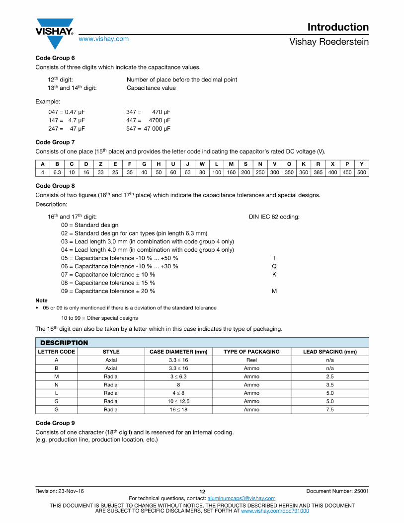
Code Group 6
Consists of three digits which indicate the capacitance values.
Example:
Code Group 7
Consists of one place (15th place) and provides the letter code indicating the capacitor’s rated DC voltage (V).
Code Group 8
Consists of two figures (16th and 17th place) which indicate the capacitance tolerances and special designs.
Description:
Note• 05 or 09 is only mentioned if there is a deviation of the standard tolerance
The 16th digit can also be taken by a letter which in this case indicates the type of packaging.
Code Group 9
Consists of one character (18th digit) and is reserved for an internal coding. (e.g. production line, production location, etc.)
12th digit: Number of place before the decimal point13th and 14th digit: Capacitance value
047 = 0.47 μF 347 = 470 μF147 = 4.7 μF 447 = 4700 μF247 = 47 μF 547 = 47 000 μF
A B C D Z E F G H U J W L M S N V O K R X P Y
4 6.3 10 16 33 25 35 40 50 60 63 80 100 160 200 250 300 350 360 385 400 450 500
16th and 17th digit: DIN IEC 62 coding:00 = Standard design02 = Standard design for can types (pin length 6.3 mm)03 = Lead length 3.0 mm (in combination with code group 4 only)04 = Lead length 4.0 mm (in combination with code group 4 only)05 = Capacitance tolerance -10 % ... +50 % T06 = Capacitance tolerance -10 % ... +30 % Q07 = Capacitance tolerance ± 10 % K08 = Capacitance tolerance ± 15 %09 = Capacitance tolerance ± 20 % M
10 to 99 = Other special designs
DESCRIPTIONLETTER CODE STYLE CASE DIAMETER (mm) TYPE OF PACKAGING LEAD SPACING (mm)
A Axial 3.3 16 Reel n/a
B Axial 3.3 16 Ammo n/a
M Radial 3 6.3 Ammo 2.5
N Radial 8 Ammo 3.5
L Radial 4 8 Ammo 5.0
G Radial 10 12.5 Ammo 5.0
G Radial 16 18 Ammo 7.5


![[PPT]Welding Symbols · Web viewWelding Symbols Understanding Welding Symbols Terms and Definitions Plug or Slot Weld Symbol Arrow Side Single-Bevel-Groove and Double Fillet weld Symbols](https://img.pdfslide.us/doc/110x75/5aaa60ff7f8b9a86188df81f/pptwelding-symbols-viewwelding-symbols-understanding-welding-symbols-terms-and.jpg)