Embed Size (px)
Citation preview
Operator Manual, Superseder III, IIIC R3.2
Page 1 of 62
TABLE OF CONTENTS
1. INTRODUCTION AND SYSTEM DESCRIPTION .................................................................. 5
2. CONDENSED OPERATING INSTRUCTIONS ....................................................................... 8
2.1 Constant Current Charge (normal mode) ............................................................................................... 8
2.2 Constant Voltage ........................................................................................................................................ 9
2.3 Peak Voltage Charge ................................................................................................................................. 9
2.4 Discharge .................................................................................................................................................. 10
2.5 BTAS Connection .................................................................................................................................... 10
See paragraph [7.8] for details on connection and operation with the BTAS16 ........................................... 10
3. SPECIFICATIONS ................................................................................................................ 11
3.1 CHARGE .................................................................................................................................................. 11
3.2 DISCHARGE ........................................................................................................................................... 12
3.3 TIMER ...................................................................................................................................................... 14
3.4 LINE INPUT VOLTAGE: ...................................................................................................................... 14
3.5 DIGITAL PANEL METERS .................................................................................................................. 15
3.6 FUSES and BREAKERS (Other than charge and discharge current limiters) ................................. 15
3.7 ENVIRONMENTAL ............................................................................................................................... 15
4. CONTROLS AND DISPLAYS .............................................................................................. 16
4.1 M1 - Ammeter .......................................................................................................................................... 16
4.2 M1 - Voltmeter ......................................................................................................................................... 16
4.3 R1 - Main Charge Current Selector ....................................................................................................... 16
4.4 R2 - Topping/Discharge Current Selector ............................................................................................. 16
4.5 SW1 - Main Time selector switch ........................................................................................................... 16
4.6 SW2 - Total Time selector switch ........................................................................................................... 16
4.7 SW3 – Keypad .......................................................................................................................................... 16
4.8 SW4 - CELL SELECTOR: ..................................................................................................................... 17
4.9 SW5 - DIGITAL VOLTMETER INPUT SELECTOR: ...................................................................... 17
4.10 SW6 - VOLTAGE MODE SELECTOR:............................................................................................... 17
4.11 SW7 - TIMER SPEED SELECTOR: .................................................................................................... 17
4.12 DS1A - RESET:........................................................................................................................................ 17
4.13 DS1B - CYC END: ................................................................................................................................... 17
4.14 DS2A - DUAL: ......................................................................................................................................... 17
4.15 DS2B - MAIN: .......................................................................................................................................... 17
4.16 DS3A - SINGLE: ...................................................................................................................................... 17
Operator Manual, Superseder III, IIIC R3.2
Page 2 of 62
4.17 DS1A - RESET:........................................................................................................................................ 17
4.18 DS1B - CYC END: ................................................................................................................................... 17
4.19 DS2A - DUAL: ......................................................................................................................................... 18
4.20 DS2B - MAIN: .......................................................................................................................................... 18
4.21 DS3A - SINGLE: ...................................................................................................................................... 18
4.22 DS3B - TOP: ............................................................................................................................................. 18
4.23 DS4A - AUTO: ......................................................................................................................................... 18
4.24 DS4B - DISCH: ........................................................................................................................................ 18
4.25 DS5A - FULL: .......................................................................................................................................... 18
4.26 DS5B - DISCH: ........................................................................................................................................ 18
4.27 DS6A - CAP FAIL: .................................................................................................................................. 18
4.28 DS6B - OPEN LIM: ................................................................................................................................. 18
4.29 DS7A - OVR TEMP: ............................................................................................................................... 18
4.30 DS7B - OVR HEAT: ................................................................................................................................ 18
4.31 DS8A - VOLT FLT: ................................................................................................................................. 19
4.32 DS8B -CURR FLT: .................................................................................................................................. 19
4.33 DS9 - CC ................................................................................................................................................... 19
4.34 DS10 - CV ................................................................................................................................................. 19
4.35 DS11 - PEAK ............................................................................................................................................ 19
4.36 AUDIBLE ALARM: ................................................................................................................................ 19
5. BTAS Interfacing ................................................................................................................. 19
5.1 Control ...................................................................................................................................................... 19
The Control Connection allows the BTAS to monitor the status of the Charger-Analyzer and also to control the Start/Stop of the operation. ............................................................................................................ 19
5.2 Shunt ......................................................................................................................................................... 19
The Shunt Connection allows the C-Scan to measure and report the Charge/Discharge Current. ............ 19
6. MODES OF OPERATION ..................................................................................................... 21
6.1 CONSTANT CURRENT CHARGE ...................................................................................................... 21
6.2 CONSTANT VOLTAGE CHARGE. ..................................................................................................... 22
6.3 PEAK CHARGE. ..................................................................................................................................... 23
6.4 DISCHARGE. .......................................................................................................................................... 24
7. OPERATING INSTRUCTIONS ............................................................................................. 25
7.1 GENERAL ............................................................................................................................................... 25
7.2 CONSTANT CURRENT CHARGE. ..................................................................................................... 26
7.3 CONSTANT VOLTAGE CHARGE ...................................................................................................... 26
7.4 PEAK VOLTAGE CHARGE: ............................................................................................................... 27
7.5 DISCHARGE ........................................................................................................................................... 28
Operator Manual, Superseder III, IIIC R3.2
Page 3 of 62
7.6 Float/Peak Voltage Chart ........................................................................................................................ 29
7.7 OPERATING NOTES AND PRECAUTIONS ..................................................................................... 30
7.8 Operation with the BTAS16 .................................................................................................................... 31
8. INSTALLATION .................................................................................................................... 31
8.1 BENCH SPACE. ...................................................................................................................................... 31
8.2 LINE VOLTAGE. .................................................................................................................................... 32
9. VERIFICATION OF PERFORMANCE .................................................................................. 34
9.1 REQUIRED TEST EQUIPMENT AND ACCESSORIES................................................................... 34
9.2 VISUAL VERIFICATION. .................................................................................................................... 34
9.3 TIMER VERIFICATION. ...................................................................................................................... 35
9.4 BATTERY OVERTEMP CUT-OFF. .................................................................................................... 36
9.5 VOLTAGE FAULT TEST. ..................................................................................................................... 36
9.6 REVERSE POLARITY TEST. .............................................................................................................. 37
9.7 OVERVOLTAGE CUT-OFF. ................................................................................................................ 37
9.8 DISCHARGE VOLTAGE CUT-OFF. ................................................................................................... 37
9.9 FULL DISCHARGE. .............................................................................................................................. 38
9.10 CURRENT TRACKING. ........................................................................................................................ 38
9.11 VOLTAGE CONTROL. ......................................................................................................................... 38
9.12 FLOAT VOLTAGE: ............................................................................................................................... 39
9.13 PEAK VOLTAGE: .................................................................................................................................. 39
9.14 METERS .................................................................................................................................................. 40
10. CALIBRATION ..................................................................................................................... 41
10.1 CIRCUIT BOARD ADJUSTMENTS AND CALIBRATION ............................................................. 41
10.2 DIGITAL METERS (see [Figure 7]). ..................................................................................................... 41
11. TROUBLESHOOTING AND REPAIRS ................................................................................ 51
11.1 TROUBLESHOOTING .......................................................................................................................... 51
11.2 FINDING A SHORTED DISCHARGE TRANSISTOR ...................................................................... 53
12. REPLACEABLE MODULES AND PARTS .......................................................................... 57
12.1 CIRCUIT BOARDS ................................................................................................................................ 57
12.2 PARTS ...................................................................................................................................................... 57
12.3 OTHER ..................................................................................................................................................... 57
13. BATTERY TESTING NOTES ............................................................................................... 58
14. DISCLAIMER ........................................................................................................................ 59
Operator Manual, Superseder III, IIIC R3.2
Page 4 of 62
14.1 This Charger-Analyzer is a precision instrument intended to be operated by personnel qualified in the servicing of aircraft, industrial or medical batteries............................................................. 59
14.2 JFM Engineering’s responsibility is limited to the repair/replacement of any malfunctioning part of the system (not responsible for any losses incurred from the usage of the system). ......................... 59
14.3 User’s Responsibility ............................................................................................................................... 59
15. REVISION INDEX ................................................................................................................. 60
TABLE OF FIGURES
Figure 1 - Block Diagram ...................................................................................................................................... 7 Figure 2 - Front Panel .......................................................................................................................................... 20 Figure 3 – Rear Panel .......................................................................................................................................... 20 Figure 4 - Line Voltage Wiring, 115V ................................................................................................................ 32 Figure 5 - Line Voltage Wiring, 208/230V ......................................................................................................... 33 Figure 6 - Line Voltage Wiring, 230/245V ......................................................................................................... 33 Figure 7 - Meters Board Adjustments (rear view) ............................................................................................... 43 Figure 8 - Control Switch Board Adjustments .................................................................................................... 44 Figure 9 - Current Control Board Adjustments ................................................................................................... 46 Figure 10 - Monitor Board Adjustments .............................................................................................................. 47 Figure 11 - Voltage Control Board Adjustments ................................................................................................. 49 Figure 12 - Circuit Board Sequence .................................................................................................................... 50 Figure 13 - Measuring for a shorted transistor ..................................................................................................... 54 Figure 14 - Location of Current Limiters ............................................................................................................ 55 Figure 15 - Power Block Diagram ....................................................................................................................... 56
TABLE OF TABLES
Table 1 - Constant Voltage and Peak Voltage Chart ........................................................................................... 29 Table 2 - Index of Revisions ................................................................................................................................ 60
Operator Manual, Superseder III, IIIC R3.2
Page 5 of 62
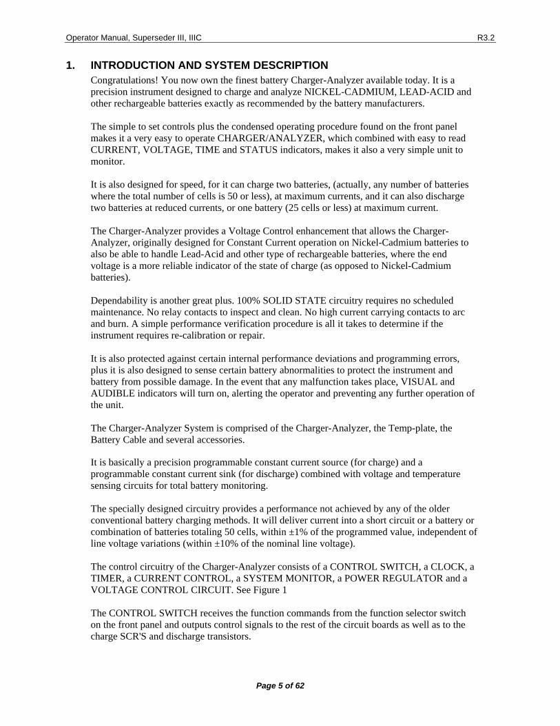
1. INTRODUCTION AND SYSTEM DESCRIPTION Congratulations! You now own the finest battery Charger-Analyzer available today. It is a precision instrument designed to charge and analyze NICKEL-CADMIUM, LEAD-ACID and other rechargeable batteries exactly as recommended by the battery manufacturers. The simple to set controls plus the condensed operating procedure found on the front panel makes it a very easy to operate CHARGER/ANALYZER, which combined with easy to read CURRENT, VOLTAGE, TIME and STATUS indicators, makes it also a very simple unit to monitor. It is also designed for speed, for it can charge two batteries, (actually, any number of batteries where the total number of cells is 50 or less), at maximum currents, and it can also discharge two batteries at reduced currents, or one battery (25 cells or less) at maximum current. The Charger-Analyzer provides a Voltage Control enhancement that allows the Charger-Analyzer, originally designed for Constant Current operation on Nickel-Cadmium batteries to also be able to handle Lead-Acid and other type of rechargeable batteries, where the end voltage is a more reliable indicator of the state of charge (as opposed to Nickel-Cadmium batteries). Dependability is another great plus. 100% SOLID STATE circuitry requires no scheduled maintenance. No relay contacts to inspect and clean. No high current carrying contacts to arc and burn. A simple performance verification procedure is all it takes to determine if the instrument requires re-calibration or repair. It is also protected against certain internal performance deviations and programming errors, plus it is also designed to sense certain battery abnormalities to protect the instrument and battery from possible damage. In the event that any malfunction takes place, VISUAL and AUDIBLE indicators will turn on, alerting the operator and preventing any further operation of the unit. The Charger-Analyzer System is comprised of the Charger-Analyzer, the Temp-plate, the Battery Cable and several accessories.
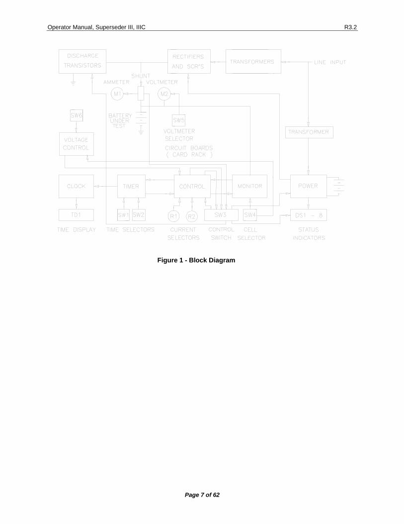
It is basically a precision programmable constant current source (for charge) and a programmable constant current sink (for discharge) combined with voltage and temperature sensing circuits for total battery monitoring. The specially designed circuitry provides a performance not achieved by any of the older conventional battery charging methods. It will deliver current into a short circuit or a battery or combination of batteries totaling 50 cells, within ±1% of the programmed value, independent of line voltage variations (within ±10% of the nominal line voltage). The control circuitry of the Charger-Analyzer consists of a CONTROL SWITCH, a CLOCK, a TIMER, a CURRENT CONTROL, a SYSTEM MONITOR, a POWER REGULATOR and a VOLTAGE CONTROL CIRCUIT. See Figure 1 The CONTROL SWITCH receives the function commands from the function selector switch on the front panel and outputs control signals to the rest of the circuit boards as well as to the charge SCR'S and discharge transistors.
Operator Manual, Superseder III, IIIC R3.2
Page 6 of 62
The TIMER provides all the required timing functions related to the charge and discharge durations. Digital time and speed selectors provide the external inputs, while the four digit readout of the CLOCK provides the elapsed time display. The CURRENT CONTROL interprets the programmed current values and controls the angle of firing of two SCR's to maintain a constant current in accordance to the feedback received from a precision shunt. Display of current is provided by an independent Digital Ammeter that uses the same shunt used by the CURRENT CONTROL circuit. Inputs from the TIMER, the SYSTEM MONITOR and the CONTROL SWITCH, determine the operating mode of the CURRENT CONTROL circuit. The SYSTEM MONITOR provides several safeguarding functions. It compares the measured current against the programmed value and if they differ by more than one ampere, operation is halted and a current malfunction is indicated. It measures the battery voltage and compares it with the programmed number of cells. From there, it determines during charge if the total voltage exceeds the equivalent of 1.75 V per cell, indicating an Overvoltage condition, or during discharge if the total voltage is below the equivalent of 1 volt per cell, indicating the end of the discharge cycle. It checks for polarity reversal at voltages as low as 0.25V, as well as an absolute Overvoltage at 85 volts, both generating a voltage malfunction indication that prevents any further operation of the unit.
It measures the temperature of the discharge heat dissipators and signals an overheat malfunction if the internal temperature exceeds 90oC, as it could be caused by a fan failure or an installation with restricted air flow. It also monitors the temperature of the batteries being charged (via the TEMP-PLATE) and terminates the charge, indicating battery Overtemp, in the event of battery overheating that may lead to thermal runaway. The POWER REGULATOR provides all regulated voltages and power amplification as required by the various circuits. The VOLTAGE CONTROL CIRCUIT provides the functions that regulate the charging current in the Constant Voltage (float) mode and in the Peak Voltage mode, transfers from Main to Topping charge on a voltage peak or ends charging on a voltage peak (new feature). The DIGITAL VOLTMETER provides internal battery voltage readings with resolutions of 0.1V and 0.01V, while a selectable external position allows single cell measurements to a resolution of 0.001V. Additional protection is provided by a high speed current limiter for the discharge transistor bank, a slow speed current limiter for the charge circuit and a magnetic circuit breaker capable of tripping under fast high current overload conditions. The Charger-Analyzer is also equipped to communicate and be controlled by the BTAS16, Computerized Battery Test System.
Operator Manual, Superseder III, IIIC R3.2
Page 7 of 62
Figure 1 - Block Diagram
Operator Manual, Superseder III, IIIC R3.2
Page 8 of 62
2. CONDENSED OPERATING INSTRUCTIONS CAUTION: Disconnect power and batteries before performing any internal maintenance. Failure to observe this caution may result in serious damage to the unit and injury to the operator. NOTE 1: Depress the RESET button before turning the power on, or before connecting or disconnecting the battery. NOTE 2: The current selector potentiometers display three digits indicating XX.X AMPS. e.g.: in order to select 4A dial 040 (04.0A), and for 20A dial 200 (20.0A).
2.1 Constant Current Charge (normal mode)
2.1.1. Number of Cells
2.1.1.1. Enter the number of cells
2.1.1.2. NOTE: when charging more than one battery enter the total number of cells.
2.1.2. Main Charge Time
2.1.2.1. Enter the MAIN CHARGE TIME and TOTAL TIME if in the TWO RATE mode, or enter the TOTAL CHARGE TIME only if in the SINGLE RATE mode.
2.1.2.2. Verify that the Timer Speed is consistent with the required elapsed time (hours or minutes).
2.1.2.3. Enter the MAIN and TOPPING CHARGE CURRENTS, if in the TWO RATE mode, or enter the TOPPING CURRENT only if in the SINGLE RATE mode.
2.1.2.4. Place batteries on the TEMP-PLATE. When working with only one battery, connect the free plug into the shorted receptacle provided in the TEMP-PLATE. Verify also that the small cable is connected to the TEMP-PLATE (the red "BATTERY OVERTEMP" INDICATOR will be on if not connected).
2.1.2.5. Depress the CONTROL BUTTON corresponding to the desired mode (white for TWO RATE and yellow for SINGLE RATE).
2.1.2.6. The charge will terminate automatically (CYCLE END) when the TOTAL TIME selected is reached.
2.1.2.7. The charge will terminate as a FAULT if the MONITOR CIRCUIT detects that:
• Battery temperature exceeds 45oC/113oF (BATTERY OVERTEMP FAULT).
• Battery voltage exceeds the equivalent of 1.75V/cell (VOLTAGE FAULT).
• The actual charge current deviates from the programmed value by more than 1 AMP (CURRENT FAULT).
Operator Manual, Superseder III, IIIC R3.2
Page 9 of 62
2.2 Constant Voltage
2.2.1. Battery Voltage
2.2.1.1. Enter the nominal battery voltage using the cell selector (see chart on page 31).
2.2.1.2. Program the charge (maximum) current in the Topping Current selector.
2.2.1.3. Program sufficient time in the Total Time selector to allow the battery to reach the required charge under constant voltage charge (consult battery manufacturers specifications). Verify that the Timer Speed is consistent with the required elapsed time.
2.2.1.4. Start the Charger-Analyzer in the Single Rate mode. The charger will begin to reduce the charging current when the battery voltage is within 0.5V of the float level.
2.2.1.5. The charge will terminate automatically (CYCLE END) when the TOTAL TIME selected is reached.
2.2.1.6. The charge will terminate as a FAULT if the MONITOR CIRCUIT detects that:
• Battery temperature exceeds 45oC/113oF (BATTERY OVERTEMP FAULT).
• The actual charge current deviates from the programmed value by more than one AMP (CURRENT FAULT). Note: this will occur only before the Charger-Analyzer switches from constant current to constant voltage.
2.3 Peak Voltage Charge
2.3.1. Nominal Battery Voltage
2.3.1.1. Enter the nominal battery voltage using the cell selector (see chart on page 31).
2.3.1.2. Select transfer from Main to Topping on Peak or stop on Peak.
2.3.1.3. Program the Main and Topping Charge currents as required.
2.3.1.4. Program the Main and Total Time selectors to allow the battery to reach the required charge level (consult battery manufacturers specifications). Verify that the Timer Speed is consistent with the required elapsed time.
2.3.1.5. Start the Charger-Analyzer in the Dual Rate mode. The charger will transfer from Main to Topping charge when the battery reaches the peak voltage or Start in the Dual or Single Rate mode and the Charger-Analyzer will stop on peak (at any part of the cycle).
2.3.1.6. The charge will terminate automatically (CYCLE END) when the TOTAL TIME selected is reached.
Operator Manual, Superseder III, IIIC R3.2
Page 10 of 62
2.3.1.7. The charge will terminate as a FAULT if the MONITOR CIRCUIT detects that:
• Battery temperature exceeds 45oC/113oF (BATTERY OVERTEMP FAULT).
• The actual charge current deviates from the programmed value by more than one AMP (CURRENT FAULT).
2.4 Discharge NOTE 1: Do not place batteries on the Temp-Plate during discharge. Due to the normal heating of the battery a false Overtemp may be generated later during the charge process. NOTE 2: Do not attempt to discharge with the voltage mode selector in the Float or Peak voltage modes. Voltage and current faults will occur depending on the battery voltage and the cell selector setting.
2.4.1. Number of Cells
2.4.1.1. Enter the number of cells.
2.4.1.2. Ignore this step if FULL DISCHARGE is to be selected.
2.4.2. Total Time
2.4.2.1. Enter the TOTAL TIME.
2.4.2.2. Verify that the Timer Speed is consistent with the required elapsed time.
2.4.2.3. Enter the DISCHARGE CURRENT.
2.4.2.4. Depress the Blue button for DISCHARGE with automatic cut-off (ANALYSIS), or the RED button for FULL DISCHARGE (DEEP CYCLE).
2.4.2.5. DISCHARGE will terminate automatically (CYCLE END) when the (TOTAL) time selected is reached or (CAPACITY FAILURE) if the BATTERY voltage reaches the equivalent of ONE VOLT per CELL prior to the selected time.
2.4.2.6. NOTE: Battery voltage is ignored during Full Discharge.
2.4.2.7. Discharge will terminate as a FAULT if the MONITOR CIRCUIT detects:
• An overheating of the discharge transistors (OVERHEAT FAULT).
• That the discharge current differs from the programmed value by more than one AMP (CURRENT FAULT).
• That the programmed current exceeds 30A for a battery voltage in excess of 32V.
2.5 BTAS Connection
See paragraph [7.8] for details on connection and operation with the BTAS16
Operator Manual, Superseder III, IIIC R3.2
Page 11 of 62
3. SPECIFICATIONS
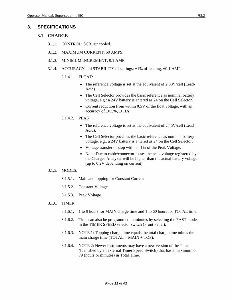
3.1 CHARGE
3.1.1. CONTROL: SCR, air cooled.
3.1.2. MAXIMUM CURRENT: 50 AMPS.
3.1.3. MINIMUM INCREMENT: 0.1 AMP.
3.1.4. ACCURACY and STABILITY of settings: ±1% of reading, ±0.1 AMP.
3.1.4.1. FLOAT:
• The reference voltage is set at the equivalent of 2.33V/cell (Lead-Acid).
• The Cell Selector provides the basic reference as nominal battery voltage, e.g.: a 24V battery is entered as 24 on the Cell Selector.
• Current reduction from within 0.5V of the float voltage, with an accuracy of ±0.5%, ±0.1A
3.1.4.2. PEAK:
• The reference voltage is set at the equivalent of 2.45V/cell (Lead-Acid).
• The Cell Selector provides the basic reference as nominal battery voltage, e.g.: a 24V battery is entered as 24 on the Cell Selector.
• Voltage transfer or stop within " 1% of the Peak Voltage. • Note: Due to cable/connector losses the peak voltage registered by
the Charger-Analyzer will be higher than the actual battery voltage (up to 0.2V depending on current).
3.1.5. MODES:
3.1.5.1. Main and topping for Constant Current
3.1.5.2. Constant Voltage
3.1.5.3. Peak Voltage
3.1.6. TIMER:
3.1.6.1. 1 to 9 hours for MAIN charge time and 1 to 60 hours for TOTAL time.
3.1.6.2. Time can also be programmed in minutes by selecting the FAST mode in the TIMER SPEED selector switch (Front Panel).
3.1.6.3. NOTE 1: Topping charge time equals the total charge time minus the main charge time (TOTAL = MAIN + TOP).
3.1.6.4. NOTE 2: Newer instruments may have a new version of the Timer (Identified by an external Timer Speed Switch) that has a maximum of 79 (hours or minutes) in Total Time.
Operator Manual, Superseder III, IIIC R3.2
Page 12 of 62
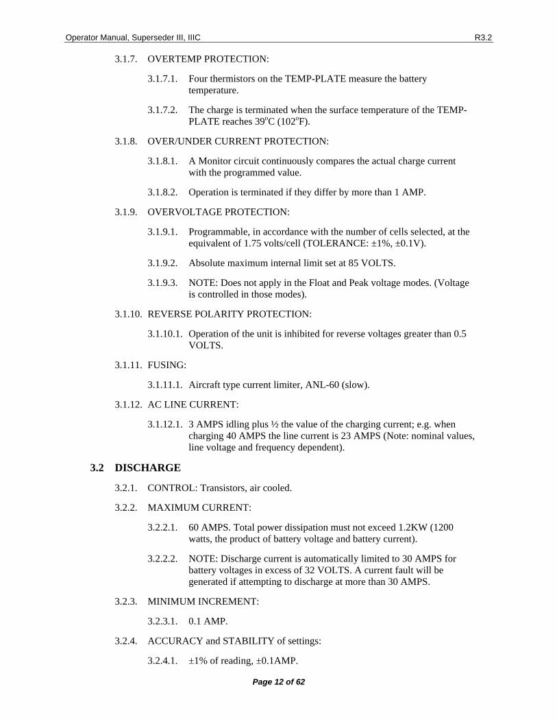
3.1.7. OVERTEMP PROTECTION:
3.1.7.1. Four thermistors on the TEMP-PLATE measure the battery temperature.
3.1.7.2. The charge is terminated when the surface temperature of the TEMP-PLATE reaches 39oC (102oF).
3.1.8. OVER/UNDER CURRENT PROTECTION:
3.1.8.1. A Monitor circuit continuously compares the actual charge current with the programmed value.
3.1.8.2. Operation is terminated if they differ by more than 1 AMP.
3.1.9. OVERVOLTAGE PROTECTION:
3.1.9.1. Programmable, in accordance with the number of cells selected, at the equivalent of 1.75 volts/cell (TOLERANCE: ±1%, ±0.1V).
3.1.9.2. Absolute maximum internal limit set at 85 VOLTS.
3.1.9.3. NOTE: Does not apply in the Float and Peak voltage modes. (Voltage is controlled in those modes).
3.1.10. REVERSE POLARITY PROTECTION:
3.1.10.1. Operation of the unit is inhibited for reverse voltages greater than 0.5 VOLTS.
3.1.11. FUSING:
3.1.11.1. Aircraft type current limiter, ANL-60 (slow).
3.1.12. AC LINE CURRENT:
3.1.12.1. 3 AMPS idling plus ½ the value of the charging current; e.g. when charging 40 AMPS the line current is 23 AMPS (Note: nominal values, line voltage and frequency dependent).
3.2 DISCHARGE
3.2.1. CONTROL: Transistors, air cooled.
3.2.2. MAXIMUM CURRENT:
3.2.2.1. 60 AMPS. Total power dissipation must not exceed 1.2KW (1200 watts, the product of battery voltage and battery current).
3.2.2.2. NOTE: Discharge current is automatically limited to 30 AMPS for battery voltages in excess of 32 VOLTS. A current fault will be generated if attempting to discharge at more than 30 AMPS.
3.2.3. MINIMUM INCREMENT:
3.2.3.1. 0.1 AMP.
3.2.4. ACCURACY and STABILITY of settings:
3.2.4.1. ±1% of reading, ±0.1AMP.
Operator Manual, Superseder III, IIIC R3.2
Page 13 of 62
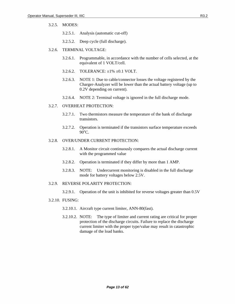
3.2.5. MODES:
3.2.5.1. Analysis (automatic cut-off)
3.2.5.2. Deep cycle (full discharge).
3.2.6. TERMINAL VOLTAGE:
3.2.6.1. Programmable, in accordance with the number of cells selected, at the equivalent of 1 VOLT/cell.
3.2.6.2. TOLERANCE: ±1% ±0.1 VOLT.
3.2.6.3. NOTE 1: Due to cable/connector losses the voltage registered by the Charger-Analyzer will be lower than the actual battery voltage (up to 0.2V depending on current).
3.2.6.4. NOTE 2: Terminal voltage is ignored in the full discharge mode.
3.2.7. OVERHEAT PROTECTION:
3.2.7.1. Two thermistors measure the temperature of the bank of discharge transistors.
3.2.7.2. Operation is terminated if the transistors surface temperature exceeds 90oC.
3.2.8. OVER/UNDER CURRENT PROTECTION:
3.2.8.1. A Monitor circuit continuously compares the actual discharge current with the programmed value
3.2.8.2. Operation is terminated if they differ by more than 1 AMP.
3.2.8.3. NOTE: Undercurrent monitoring is disabled in the full discharge mode for battery voltages below 2.5V.
3.2.9. REVERSE POLARITY PROTECTION:
3.2.9.1. Operation of the unit is inhibited for reverse voltages greater than 0.5V
3.2.10. FUSING:
3.2.10.1. Aircraft type current limiter, ANN-80(fast).
3.2.10.2. NOTE: The type of limiter and current rating are critical for proper protection of the discharge circuits. Failure to replace the discharge current limiter with the proper type/value may result in catastrophic damage of the load banks.
Operator Manual, Superseder III, IIIC R3.2
Page 14 of 62
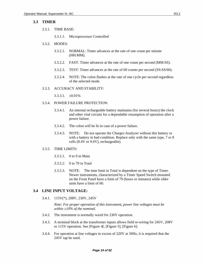
3.3 TIMER
3.3.1. TIME BASE:
3.3.1.1. Microprocessor Controlled
3.3.2. MODES:
3.3.2.1. NORMAL: Timer advances at the rate of one count per minute (HH:MM).
3.3.2.2. FAST: Timer advances at the rate of one count per second (MM:SS).
3.3.2.3. TEST: Timer advances at the rate of 60 counts per second (SS:SS/60).
3.3.2.4. NOTE: The colon flashes at the rate of one cycle per second regardless of the selected mode.
3.3.3. ACCURACY AND STABILITY:
3.3.3.1. ±0.01%
3.3.4. POWER FAILURE PROTECTION:
3.3.4.1. An internal rechargeable battery maintains (for several hours) the clock and other vital circuits for a dependable resumption of operation after a power failure.
3.3.4.2. The colon will be lit in case of a power failure.
3.3.4.3. NOTE: Do not operate the Charger-Analyzer without this battery or with a battery in bad condition. Replace only with the same type, 7 or 8 cells (8.4V or 9.6V), rechargeable).
3.3.5. TIME LIMITS:
3.3.5.1. 0 to 9 in Main
3.3.5.2. 0 to 79 in Total
3.3.5.3. NOTE: The time limit in Total is dependent on the type of Timer. Newer instruments, characterized by a Timer Speed Switch mounted on the Front Panel have a limit of 79 (hours or minutes) while older units have a limit of 60.
3.4 LINE INPUT VOLTAGE:
3.4.1. 115V(*), 208V, 230V, 245V
Note: For proper operation of this instrument, power line voltages must be within ±10% of the nominal.
3.4.2. The instrument is normally wired for 230V operation.
3.4.3. A terminal block at the transformer inputs allows field re-wiring for 245V, 208V or 115V operation. See [Figure 4[, [Figure 5], [Figure 6].
3.4.4. For operation at line voltages in excess of 220V at 50Hz, it is required that the 245V tap be used.
Operator Manual, Superseder III, IIIC R3.2
Page 15 of 62
3.4.5. NOTE (*): Operation at 115V is not recommended at battery charging currents above 15A due to the increased line current.
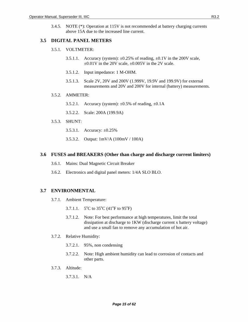
3.5 DIGITAL PANEL METERS
3.5.1. VOLTMETER:
3.5.1.1. Accuracy (system): ±0.25% of reading, ±0.1V in the 200V scale, ±0.01V in the 20V scale, ±0.005V in the 2V scale.
3.5.1.2. Input impedance: 1 M-OHM.
3.5.1.3. Scale 2V, 20V and 200V (1.999V, 19.9V and 199.9V) for external measurements and 20V and 200V for internal (battery) measurements.
3.5.2. AMMETER:
3.5.2.1. Accuracy (system): ±0.5% of reading, ±0.1A
3.5.2.2. Scale: 200A (199.9A)
3.5.3. SHUNT:
3.5.3.1. Accuracy: ±0.25%
3.5.3.2. Output: 1mV/A (100mV / 100A)
3.6 FUSES and BREAKERS (Other than charge and discharge current limiters)
3.6.1. Mains: Dual Magnetic Circuit Breaker
3.6.2. Electronics and digital panel meters: 1/4A SLO BLO.
3.7 ENVIRONMENTAL
3.7.1. Ambient Temperature:
3.7.1.1. 5oC to 35oC (41oF to 95oF)
3.7.1.2. Note: For best performance at high temperatures, limit the total dissipation at discharge to 1KW (discharge current x battery voltage) and use a small fan to remove any accumulation of hot air.
3.7.2. Relative Humidity:
3.7.2.1. 95%, non condensing
3.7.2.2. Note: High ambient humidity can lead to corrosion of contacts and other parts.
3.7.3. Altitude:
3.7.3.1. N/A
Operator Manual, Superseder III, IIIC R3.2
Page 16 of 62
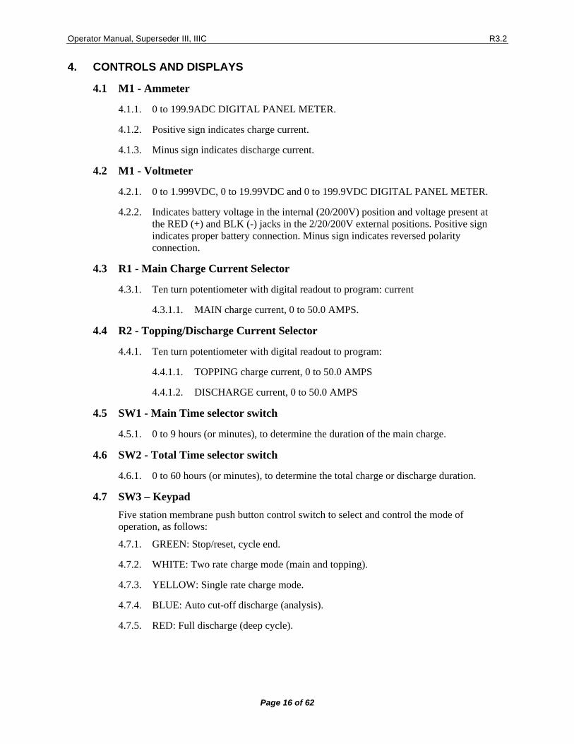
4. CONTROLS AND DISPLAYS
4.1 M1 - Ammeter
4.1.1. 0 to 199.9ADC DIGITAL PANEL METER.
4.1.2. Positive sign indicates charge current.
4.1.3. Minus sign indicates discharge current.
4.2 M1 - Voltmeter
4.2.1. 0 to 1.999VDC, 0 to 19.99VDC and 0 to 199.9VDC DIGITAL PANEL METER.
4.2.2. Indicates battery voltage in the internal (20/200V) position and voltage present at the RED (+) and BLK (-) jacks in the 2/20/200V external positions. Positive sign indicates proper battery connection. Minus sign indicates reversed polarity connection.
4.3 R1 - Main Charge Current Selector
4.3.1. Ten turn potentiometer with digital readout to program: current
4.3.1.1. MAIN charge current, 0 to 50.0 AMPS.
4.4 R2 - Topping/Discharge Current Selector
4.4.1. Ten turn potentiometer with digital readout to program:
4.4.1.1. TOPPING charge current, 0 to 50.0 AMPS
4.4.1.2. DISCHARGE current, 0 to 50.0 AMPS
4.5 SW1 - Main Time selector switch
4.5.1. 0 to 9 hours (or minutes), to determine the duration of the main charge.
4.6 SW2 - Total Time selector switch
4.6.1. 0 to 60 hours (or minutes), to determine the total charge or discharge duration.
4.7 SW3 – Keypad Five station membrane push button control switch to select and control the mode of operation, as follows:
4.7.1. GREEN: Stop/reset, cycle end.
4.7.2. WHITE: Two rate charge mode (main and topping).
4.7.3. YELLOW: Single rate charge mode.
4.7.4. BLUE: Auto cut-off discharge (analysis).
4.7.5. RED: Full discharge (deep cycle).
Operator Manual, Superseder III, IIIC R3.2
Page 17 of 62
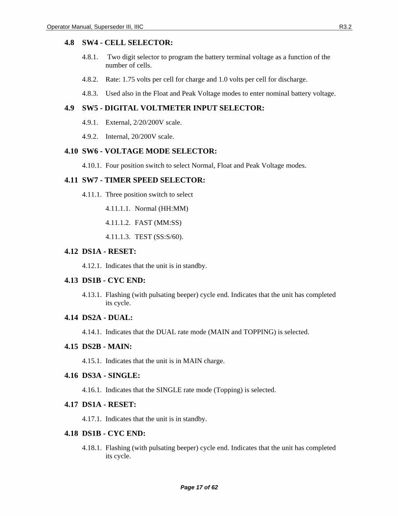
4.8 SW4 - CELL SELECTOR:
4.8.1. Two digit selector to program the battery terminal voltage as a function of the number of cells.
4.8.2. Rate: 1.75 volts per cell for charge and 1.0 volts per cell for discharge.
4.8.3. Used also in the Float and Peak Voltage modes to enter nominal battery voltage.
4.9 SW5 - DIGITAL VOLTMETER INPUT SELECTOR:
4.9.1. External, 2/20/200V scale.
4.9.2. Internal, 20/200V scale.
4.10 SW6 - VOLTAGE MODE SELECTOR:
4.10.1. Four position switch to select Normal, Float and Peak Voltage modes.
4.11 SW7 - TIMER SPEED SELECTOR:
4.11.1. Three position switch to select
4.11.1.1. Normal (HH:MM)
4.11.1.2. FAST (MM:SS)
4.11.1.3. TEST (SS:S/60).
4.12 DS1A - RESET:
4.12.1. Indicates that the unit is in standby.
4.13 DS1B - CYC END:
4.13.1. Flashing (with pulsating beeper) cycle end. Indicates that the unit has completed its cycle.
4.14 DS2A - DUAL:
4.14.1. Indicates that the DUAL rate mode (MAIN and TOPPING) is selected.
4.15 DS2B - MAIN:
4.15.1. Indicates that the unit is in MAIN charge.
4.16 DS3A - SINGLE:
4.16.1. Indicates that the SINGLE rate mode (Topping) is selected.
4.17 DS1A - RESET:
4.17.1. Indicates that the unit is in standby.
4.18 DS1B - CYC END:
4.18.1. Flashing (with pulsating beeper) cycle end. Indicates that the unit has completed its cycle.
Operator Manual, Superseder III, IIIC R3.2
Page 18 of 62
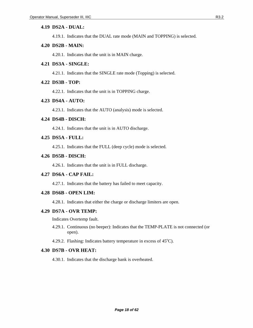
4.19 DS2A - DUAL:
4.19.1. Indicates that the DUAL rate mode (MAIN and TOPPING) is selected.
4.20 DS2B - MAIN:
4.20.1. Indicates that the unit is in MAIN charge.
4.21 DS3A - SINGLE:
4.21.1. Indicates that the SINGLE rate mode (Topping) is selected.
4.22 DS3B - TOP:
4.22.1. Indicates that the unit is in TOPPING charge.
4.23 DS4A - AUTO:
4.23.1. Indicates that the AUTO (analysis) mode is selected.
4.24 DS4B - DISCH:
4.24.1. Indicates that the unit is in AUTO discharge.
4.25 DS5A - FULL:
4.25.1. Indicates that the FULL (deep cycle) mode is selected.
4.26 DS5B - DISCH:
4.26.1. Indicates that the unit is in FULL discharge.
4.27 DS6A - CAP FAIL:
4.27.1. Indicates that the battery has failed to meet capacity.
4.28 DS6B - OPEN LIM:
4.28.1. Indicates that either the charge or discharge limiters are open.
4.29 DS7A - OVR TEMP: Indicates Overtemp fault.
4.29.1. Continuous (no beeper): Indicates that the TEMP-PLATE is not connected (or open).
4.29.2. Flashing: Indicates battery temperature in excess of 45oC).
4.30 DS7B - OVR HEAT:
4.30.1. Indicates that the discharge bank is overheated.
Operator Manual, Superseder III, IIIC R3.2
Page 19 of 62
4.31 DS8A - VOLT FLT: Indicates voltage fault.
4.31.1. Continuous: battery connected with polarity reversed.
4.31.2. Flashing: (during charge) battery voltage in excess of 1.75 volts per cell or in excess of 85 volts, or open circuit.
4.32 DS8B -CURR FLT:
4.32.1. Indicates that the actual current differs from the programmed value by more than 1A.
4.33 DS9 - CC
4.33.1. Indicates that the charger is in the basic Constant Current mode.
4.34 DS10 - CV
4.34.1. Indicates that the charger is in the Constant Current/Float mode.
4.35 DS11 - PEAK
4.35.1. Indicates that the charger is in the Constant Current/Peak mode.
4.36 AUDIBLE ALARM:
4.36.1. Continuous: turns on with any of the faults.
4.36.2. Pulsating: turns on with cycle end.
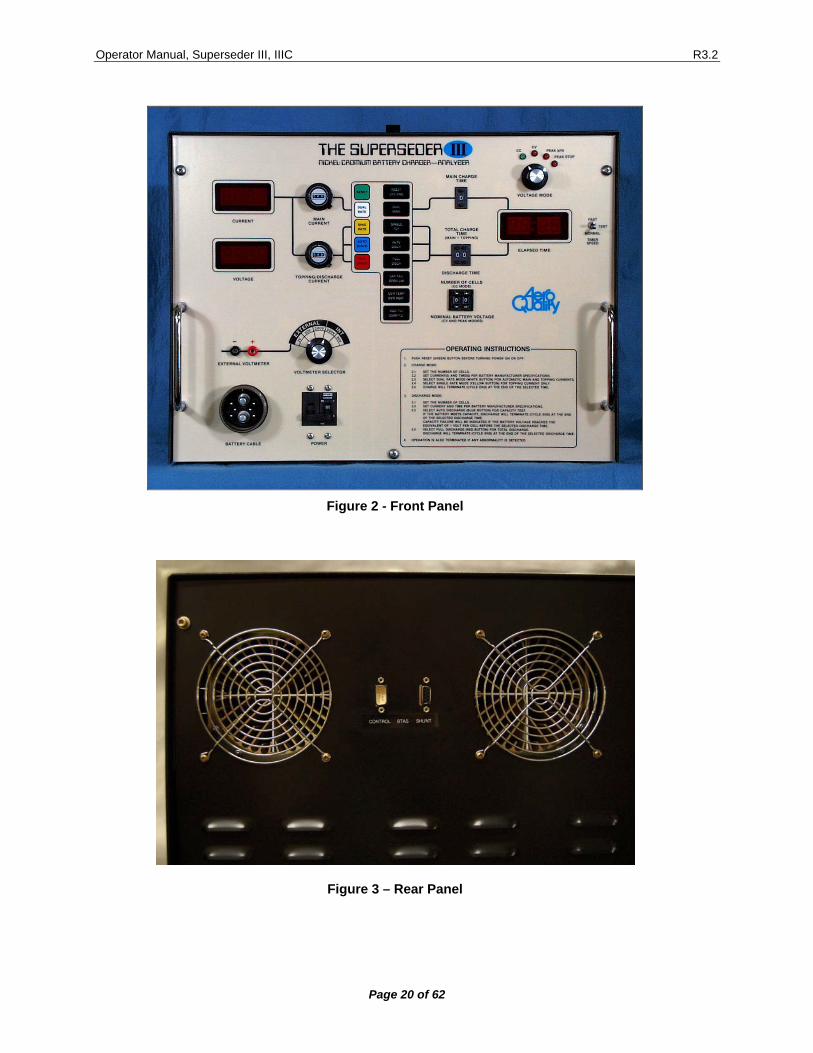
5. BTAS Interfacing The Charger-Analyzer is equipped with connections for the BTAS16 Computerized Battery Test System. See [Figure 3].
5.1 Control
The Control Connection allows the BTAS to monitor the status of the Charger-Analyzer and also to control the Start/Stop of the operation.
5.2 Shunt
The Shunt Connection allows the C-Scan to measure and report the Charge/Discharge Current.
Operator Manual, Superseder III, IIIC R3.2
Page 20 of 62
Figure 2 - Front Panel
Figure 3 – Rear Panel
Operator Manual, Superseder III, IIIC R3.2
Page 21 of 62
6. MODES OF OPERATION
6.1 CONSTANT CURRENT CHARGE
6.1.1. DUAL RATE:
6.1.1.1. The battery is charged at the main rate for a preset time, at the end of which, the current is switched automatically to the topping rate for the remainder of the total time selected.
6.1.1.2. Charging is automatically terminated at the end of the total time selected (cycle end), or as a fault if:
• Battery overtemperature is detected (Overtemp fault). • Battery voltage is in excess of 1.75V/cell as determined by the
number of cells programmed, or if the battery voltage is in excess of 85V (voltage fault).
• Actual charging current differs from the programmed value by more than 1 AMP (current fault).
6.1.1.3. Charge operation may be terminated at any time by depressing the RESET (green) button.
6.1.2. SINGLE RATE:
6.1.2.1. The battery is charged at the topping rate for a preset time.
6.1.2.2. Charging is automatically terminated at the end of the total time selected (cycle end), or as a fault if:
• Battery overtemperature is detected (Overtemp fault). • Battery voltage is in excess of 1.75V/cell as determined by the
number of cells programmed, or if battery voltage is in excess of 85V (voltage fault).
• Actual charging current differs from the programmed value by more than 1 AMP (current fault).
6.1.2.3. Charge operation may be terminated at any time by depressing the (green) reset button.
Operator Manual, Superseder III, IIIC R3.2
Page 22 of 62
6.2 CONSTANT VOLTAGE CHARGE
6.2.1. The battery is charged at the topping rate for a preset time.
6.2.2. When the battery voltage is within 0.5V of the selected float voltage, the charging current begins to diminish, and settles to the level of current required to maintain the battery at the selected float voltage.
6.2.3. Charging is automatically terminated at the end of the total time selected (cycle end), or as a fault if:
• Battery overtemperature is detected (Overtemp fault). • Battery voltage is in excess of 85V (voltage fault). • Actual charging current differs from the programmed value by more than 1
AMP (current fault). Note: applicable only before the charger switches from constant current to constant voltage.
6.2.4. Charge operation may be terminated at any time by depressing the (green) reset button.
Operator Manual, Superseder III, IIIC R3.2
Page 23 of 62
6.3 PEAK CHARGE
6.3.1. Transfer from Main to Topping on Peak voltage.
6.3.1.1. The battery is charged at the main rate for a preset time.
6.3.1.2. When the battery voltage reaches the programmed peak voltage, the charging current transfers from main to topping.
6.3.1.3. Charging is automatically terminated at the end of the total time selected (cycle end), or as a fault if:
• Battery overtemperature is detected (Overtemp fault). • Battery voltage is in excess of 85V (voltage fault). • Actual charging current differs from the programmed value by
more than 1 AMP (current fault). • NOTE: Charge operation may be terminated at any time by
depressing the (green) reset button.
6.3.2. Stop on Peak Voltage.
6.3.2.1. The battery is charged at the main rate for a preset time.
6.3.2.2. When the battery voltage reaches the programmed peak voltage, the charging current stops.
6.3.2.3. Charging is automatically terminated at the end of the total time selected (cycle end), or as a fault if:
• Battery overtemperature is detected (Overtemp fault). • Battery voltage is in excess of 85V (voltage fault). • Actual charging current differs from the programmed value by
more than 1 AMP (current fault). • NOTE: Charge operation may be terminated at any time by
depressing the (green) reset button.

Operator Manual, Superseder III, IIIC R3.2
Page 24 of 62
6.4 DISCHARGE NOTE: For battery voltages greater than 32V, the discharge current is automatically limited to 30A. A current fault condition will result if more than 30A is programmed.
6.4.1. ANALYSIS (AUTO CUT-OFF):
6.4.1.1. The battery is discharged at the selected rate for a preset time.
6.4.1.2. Discharge is automatically terminated (cycle end), at the end of the time selected or if the battery voltage reaches the equivalent of 1 VOLT/cell (capacity failure), as determined by the number of cells programmed, or it is terminated as a fault, if:
• The actual discharge current differs from the programmed value by more than 1 AMP (current fault).
• Overheating of the transistor heat sinks is detected (overheat fault). • NOTE: Discharge operation can be terminated at any time by
depressing the (green) reset button.
6.4.2. DEEP CYCLE (FULL DISCHARGE):
6.4.2.1. The battery is discharged at the selected rate for a preset time.
6.4.2.2. Discharge is automatically terminated (cycle end) at the end of the time selected, or as a fault, if:
• The actual discharge current differs from the programmed value by more than 1 AMP (current fault). NOTE: Undercurrent fault monitoring is disabled at battery voltages below 2V.
• Overheating of the transistor heat sinks is detected (overheat fault).
Operator Manual, Superseder III, IIIC R3.2
Page 25 of 62
7. OPERATING INSTRUCTIONS
7.1 GENERAL
7.1.1. Verify RESET
7.1.1.1. Verify that the reset button is depressed before turning power on.
7.1.2. Connect the Battery
7.1.2.1. Connect the battery cable to the batteries and the Temp-Plate.
7.1.2.2. If only one battery is used, connect the free plug to the shorted receptacle provided in the Temp-Plate.
7.1.2.3. Observe polarity when using the single cell adaptor.
7.1.2.4. If battery polarity is reversed, a voltage fault condition will be indicated and further operation of the instrument will be inhibited.
7.1.3. Verify Voltmeter
7.1.3.1. The digital voltmeter will read battery voltage if the selector switch is in the internal position.
7.1.3.2. Select the scale consistent with the battery voltage.
7.1.4. Program the number of cells.
7.1.4.1. Enter the number of cells of the battery
7.1.4.2. When working with more than one battery enter the TOTAL number of cells.
7.1.4.3. Note 1: In the full discharge mode the number of cells is ignored.
7.1.4.4. Note 2: In the Float and Peak voltage modes, the cell selector becomes a nominal battery voltage selector. See xxx
Operator Manual, Superseder III, IIIC R3.2
Page 26 of 62
7.2 CONSTANT CURRENT CHARGE
7.2.1. Main Charge
7.2.1.1. Program Main charging rate and time duration.
7.2.1.2. Verify that the Timer Speed is consistent with the required elapsed time.
7.2.2. Topping Charge
7.2.2.1. Program Topping charging rate and total time of charge (Total time = Main + Topping Times).
7.2.2.2. Start in Dual Rate
7.2.2.3. Depress the Two Rate (white) control button.
7.2.2.4. DUAL and MAIN indicators will turn on and current will rise to the set rate in about three to five seconds.
7.2.2.5. Verify colon(:)
• The colon in the digital time display will flash a the rate of one cycle per second.
7.2.3. Single Rate Charge
7.2.3.1. For a single rate, program the current using the Topping selector
7.2.3.2. Set the required (total) time and depress the single rate (yellow) control button.
7.2.3.3. The SING and TOP indicators will turn on and battery current will rise to the set rate in about three to five seconds.
7.3 CONSTANT VOLTAGE CHARGE
7.3.1. Nominal Battery Voltage
7.3.1.1. Enter the nominal battery voltage using the cell selector (see chart on page 19).
7.3.2. Maximum Charge Current
7.3.2.1. Program the maximum charge current using the Topping Current selector.
7.3.3. Time
7.3.3.1. Program sufficient time in the Total Time selector to allow the battery to reach the required charge level (consult battery manufacturers specifications).
7.3.3.2. Verify that the Timer Speed is consistent with the required elapsed time.
Operator Manual, Superseder III, IIIC R3.2
Page 27 of 62
7.3.4. RUN
7.3.4.1. Start the Charger-Analyzer in the Single Rate mode. The charger will start to reduce the charging current when the battery voltage is within 0.5V of the float level.
7.3.4.2. The charge will terminate automatically (CYCLE END) when the TOTAL TIME selected is reached.
7.3.4.3. The charge will terminate as a FAULT if the MONITOR CIRCUIT detects that:
• Battery temperature exceeds 45oC/113oF (BATTERY OVERTEMP FAULT).
• The actual charge current deviates from the programmed value by more than 1A (CURRENT FAULT).
7.4 PEAK VOLTAGE CHARGE
7.4.1. Nominal Battery Voltage
7.4.1.1. Enter the nominal battery voltage using the Cell selector (see chart on page 19).
7.4.1.2. Select transfer from Main to Topping on Peak Voltage or stop on Peak Voltage.
7.4.2. Charge Currents
7.4.2.1. Program the Main and Topping Charge currents as required.
7.4.3. Time
7.4.3.1. Program the Main and Total Time selectors to allow the battery to reach the required charge level (consult battery manufacturers specifications).
7.4.3.2. Verify that the Timer Speed is consistent with the required elapsed time.
7.4.4. RUN
7.4.4.1. Start the Charger-Analyzer in the Dual Rate mode. If transfer on peak is selected, the charger will transfer from Main to Topping charge when the battery reaches the peak voltage. If stop on peak is selected, the Charger stop upon reaching the peak voltage.
7.4.4.2. The charge will terminate automatically (CYCLE END) when the TOTAL TIME selected is reached.
7.4.4.3. The charge will terminate as a FAULT if the MONITOR CIRCUIT detects that:
• Battery temperature exceeds 45oC/113oF (BATTERY OVERTEMP FAULT).
• The actual charge current deviates from the programmed value by more than 1A (CURRENT FAULT).
Operator Manual, Superseder III, IIIC R3.2
Page 28 of 62
7.5 DISCHARGE NOTE: Do not discharge batteries on the Temp-Plate. Normal battery heating of the Temp-Plate during discharge will generate a false battery Overtemp fault when attempting to recharge it.
7.5.1. Current and Time
7.5.1.1. Program the discharge rate and time duration.
7.5.1.2. Verify that the Timer Speed is consistent with the required elapsed time.
7.5.2. RUN
7.5.2.1. Depress auto discharge (BLUE) control button, for analysis to one volt per cell.
7.5.2.2. Depress full discharge (RED) control button for battery deep cycling.
7.5.2.3. DISCHARGE will terminate automatically (CYCLE END) when the (TOTAL) time selected is reached or (CAPACITY FAILURE) if the BATTERY voltage reaches the equivalent of ONE VOLT per CELL prior to the selected time.
7.5.2.4. NOTE: Battery voltage is ignored during full discharge.
7.5.2.5. Discharge will terminate as a FAULT if the MONITOR CIRCUIT detects:
• An overheating of the discharge transistors (OVERHEAT FAULT).
• That the discharge current differs from the programmed value by more than one AMP (CURRENT FAULT).
• That the programmed current exceeds 30A for a battery voltage in excess of 32V.
Operator Manual, Superseder III, IIIC R3.2
Page 29 of 62
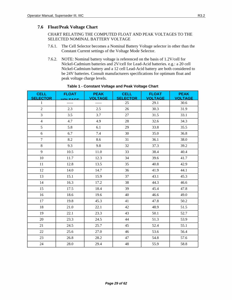
7.6 Float/Peak Voltage Chart CHART RELATING THE COMPUTED FLOAT AND PEAK VOLTAGES TO THE SELECTED NOMINAL BATTERY VOLTAGE
7.6.1. The Cell Selector becomes a Nominal Battery Voltage selector in other than the Constant Current settings of the Voltage Mode Selector.
7.6.2. NOTE: Nominal battery voltage is referenced on the basis of 1.2V/cell for Nickel-Cadmium batteries and 2V/cell for Lead-Acid batteries. e.g.: a 20 cell Nickel-Cadmium battery and a 12 cell Lead-Acid battery are both considered to be 24V batteries. Consult manufacturers specifications for optimum float and peak voltage charge levels.
Table 1 - Constant Voltage and Peak Voltage Chart
CELL SELECTOR
FLOAT VOLTAGE
PEAK VOLTAGE
CELL SELECTOR
FLOAT VOLTAGE
PEAK VOLTAGE
1 ----- ----- 25 29.1 30.6 2 2.3 2.5 26 30.3 31.9 3 3.5 3.7 27 31.5 33.1 4 4.7 4.9 28 32.6 34.3 5 5.8 6.1 29 33.8 35.5 6 6.7 7.4 30 35.0 36.8 7 8.2 8.6 31 36.1 38.0 8 9.3 9.8 32 37.3 39.2 9 10.5 11.0 33 38.4 40.4
10 11.7 12.3 34 39.6 41.7 11 12.8 13.5 35 40.8 42.9 12 14.0 14.7 36 41.9 44.1 13 15.1 15.9 37 43.1 45.3 14 16.3 17.2 38 44.3 46.6 15 17.5 18.4 39 45.4 47.8 16 18.6 19.6 40 46.6 49.0 17 19.8 45.3 41 47.8 50.2 18 21.0 22.1 42 48.9 51.5 19 22.1 23.3 43 50.1 52.7 20 23.3 24.5 44 51.3 53.9 21 24.5 25.7 45 52.4 55.1 22 25.6 27.0 46 53.6 56.4 23 26.8 28.2 47 54.8 57.6 24 28.0 29.4 48 55.9 58.8
Operator Manual, Superseder III, IIIC R3.2
Page 30 of 62
7.7 OPERATING NOTES AND PRECAUTIONS
7.7.1. Make sure that the instrument is in the reset position before turning power on or off, or before connecting or disconnecting batteries.
7.7.2. When a cycle is terminated either automatically or by resetting, wait about two to three seconds before re-starting in any mode (the control switch circuit has a time delay that ignores switch selections during a 2 to 3 second interval).
7.7.3. It is possible to alternate between the two discharge modes or from the dual rate to the single charge rate mode while the unit is in operation, but the charger must be reset before switching to an opposite mode (e.g. from charge to discharge or vice versa).
• NOTE: The control switch circuit ignores mode change requests without previous resetting of the charger.
7.7.4. If the discharge current limiter opens it is still possible to operate in the charge mode (by setting the switch in the Monitor board to Test), but if the charge current limiter opens, the unit is rendered completely inoperative.
7.7.5. It is imperative that the current limiter and fuses be replaced with the same type and value.
7.7.5.1. Failure to do so will result in serious damage to the control and power circuitry of the instrument.
7.7.5.2. Failure to observe this requirement will void the warranty.
7.7.6. Do not block air circulation. A substantial amount of heat must be dissipated, particularly in the discharge mode (up to 1KW).
• External heat removal (circulating fan) is required when operating in confined spaces or hot environments.
7.7.7. Do not disconnect the battery cable while the unit is in operation.
• Large current surges can occur, with corresponding arcing, that can damage the charger, the connectors and the battery.
7.7.8. Disconnect batteries and power from the instrument (remove the line cord from the wall outlet) before changing circuit boards and current limiters or to perform maintenance or repairs.
• Failure to do so can result in serious (lethal) personal injury and/or serious damage to the instrument.
7.7.9. Do not exceed a setting of 79 in the total time selector.
• If exceeded, times will be inconsistent with the dialed settings.
7.7.10. Do not run the unit with the monitor switch in the test position (except for tests). Loss of protection will occur.
7.7.11. Do not perform battery work on bare metal table tops.
7.7.12. Do not attempt to discharge with the Voltage Mode Selector in the CV or PEAK positions.
• Voltage and currents faults will result depending on the battery voltage and cell selector settings.
Operator Manual, Superseder III, IIIC R3.2
Page 31 of 62
7.8 Operation with the BTAS16
7.8.1. Connect the Control Cable to the C-Scan
7.8.2. Connect the Shunt Cable to the S-Scan
7.8.3. Associate the Charger to the C-Scan. (see Charger Type and Charger ID in the Main Screen of the BTAS16).
7.8.4. Chose to Link the Charger-Analyzer for automatic start-stop control by the BTAS16 or leave unchecked for manual operation.
7.8.5. Manual Mode:
7.8.5.1. Program and start the Charger-Analyzer first and allow a few seconds for the current to rise to the final value before starting the test in the BTAS16 Main Screen.
7.8.6. Automatic Mode:
7.8.6.1. Program and start the Charger-Analyzer (the Charger-Analyzer will be on hold by the BTAS16) and then start the test in the BTAS16 Main Screen. The BTAS16 will start first the Charger-Analyzer and after a few seconds, the data recording will start.
8. INSTALLATION
8.1 BENCH SPACE
8.1.1. The Charger-Analyzer system occupies 19" x 17" (48.3 cm x 43.2 cm) of table top space for the charger and 10" x 25" (25 cm X 63.5 cm) for the Temp-Plate.
8.1.2. Allow also at least 6" (15.2 cm) of separation from the wall and adjacent equipment, in order to maintain proper air flow (VITAL!).
8.1.3. NOTE 1: In non air-conditioned rooms or if other heat dissipating equipment are nearby, it is recommended that circulating or extracting fans be used to aid in the heated air removal.
8.1.4. NOTE 2: Operation in dusty or otherwise "dirty" air environments will severely reduce the cooling capacity of the fans and lead to premature failure.
Operator Manual, Superseder III, IIIC R3.2
Page 32 of 62
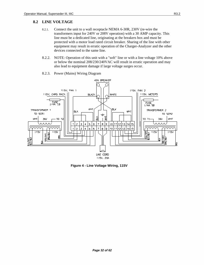
8.2 LINE VOLTAGE
8.2.1. Connect the unit to a wall receptacle NEMA 6-30R, 230V (re-wire the transformers input for 240V or 208V operation) with a 30 AMP capacity. This line must be a dedicated line, originating at the breakers box and must be protected with a motor load rated circuit breaker. Sharing of the line with other equipment may result in erratic operation of the Charger-Analyzer and the other devices connected to the same line.
8.2.2. NOTE: Operation of this unit with a "soft" line or with a line voltage 10% above or below the nominal 208/230/240VAC will result in erratic operation and may also lead to equipment damage if large voltage surges occur.
8.2.3. Power (Mains) Wiring Diagram
Figure 4 - Line Voltage Wiring, 115V
Operator Manual, Superseder III, IIIC R3.2
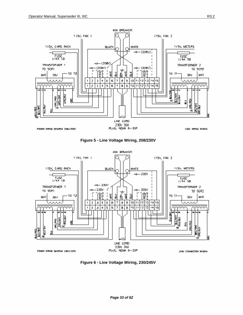
Page 33 of 62
Figure 5 - Line Voltage Wiring, 208/230V
Figure 6 - Line Voltage Wiring, 230/245V
Operator Manual, Superseder III, IIIC R3.2
Page 34 of 62
9. VERIFICATION OF PERFORMANCE
The Charger-Analyzer has been designed, manufactured and tested to give thousands of hours of trouble free operation, but if you find that your unit is not performing properly (or as expected), please refer first to the operating instructions for re-assurance that proper procedures are being followed. If it is determined then, that your Charger-Analyzer is malfunctioning or appears to be malfunctioning, please refer to the verification of performance, calibration and troubleshooting sections which will show you how to use the various built-in test features to determine or approximate the nature of the problem. NOTE 1: The Charger-Analyzer is a precision instrument. Use only certified instrumentation capable of accuracies of at least 0.25% on voltage and 0.5% on current. • The CAL-100 Battery Charger-Analyzer Calibrator provides all necessary functions to
monitor, verify and calibrate the Charger-Analyzer. NOTE 2: In the following tests make no connection to a battery unless specifically indicated. Always start from reset and always reset at the conclusion of a test.
9.1 REQUIRED TEST EQUIPMENT AND ACCESSORIES
9.1.1. CAL-100 Calibrator and one 20 to 50A-Hr 20 cell battery
9.1.2. IF a CAL-100 Calibrator is not available, the following items are required in addition to the battery mentioned in (a) .
9.1.2.1. Power Supply capable of 60V output with very little current capability (less than 20mA).
9.1.2.2. Ammeter or Shunt capable of at least 50A
9.1.2.3. Digital Voltmeter, 3-1/2 digits or better.
9.1.2.4. Four each of 16.5K, 17.5K and 30.1K 1% resistors (1/4W)
9.2 VISUAL VERIFICATION
9.2.1. Set the Voltage Mode Selector to CC (first position).
9.2.2. Turn power on.
9.2.3. Verify the following:
9.2.3.1. Reset/cycle end (green) light must be on
9.2.3.2. The digital panel meters must read zero
9.2.3.3. The elapsed time display must read zero (colon must be off).
Operator Manual, Superseder III, IIIC R3.2
Page 35 of 62
9.3 TIMER VERIFICATION
9.3.1. Settings:
9.3.1.1. Set the Main and Topping Charge Current Selectors to zero.
9.3.1.2. Set both Time Selectors to zero.
9.3.1.3. Set the Timer Speed Switch to the test (center) position.
9.3.2. NOTE: Current and voltage readings must remain at zero during the following tests. If voltage starts to rise, which may lead to voltage a fault, verify that the current selectors are completely at zero.
9.3.3. Start the unit by depressing the two rate charge selector.
9.3.3.1. The unit will go immediately into Cycle End.
9.3.3.2. Reset.
9.3.4. Set the total time to 01 and start.
9.3.4.1. Unit will start in main charge and immediately transfer to topping, going into cycle end after one second.
9.3.4.2. Reset.
9.3.5. Set the main time to 1, total time to 02 and start.
9.3.5.1. The unit will start in the main mode, transfer to topping after one second and go into cycle end after two seconds.
9.3.5.2. Reset.
9.3.6. Repeat the above tests, each time advancing the main and total time selectors as follows: 2/04, 4/08, 8/09, 9/10, 9/20, 9/40 and 9/79 (or 9/60 depending on the type of Timer).
Operator Manual, Superseder III, IIIC R3.2
Page 36 of 62
9.4 BATTERY OVERTEMP CUT-OFF
9.4.1. Settings:
9.4.1.1. Set current selectors to zero.
9.4.1.2. Set the timer speed switch in the normal position (to the right).
9.4.1.3. Set time selectors to 1/01 and cell selector to 20.
9.4.1.4. Connect the battery cable to the unit but make no battery or Temp-Plate connections. The red Overtemp light will be on.
9.4.2. Temp-Plate simulations resistors:
9.4.2.1. Connect one 16.5 K-OHM (1%) resistor between pins D and B
9.4.2.2. Connect one each 30.1 K-OHM (1%) resistors between pins D and C, D and E, and D and H.
9.4.2.3. The red light will turn off.
9.4.3. Start in either of the charge modes.
9.4.3.1. The unit will start and immediately go into Overtemp fault (red light flashing and alarm on).
9.4.3.2. Reset.
9.4.4. Repeat the previous test by rotating the 16.5 K-OHM resistor in all four positions.
9.4.5. Repeat the first test using four 17.5 K-OHM (1%) resistors.
9.4.5.1. The unit must not show Overtemp fault.
9.5 VOLTAGE FAULT TEST
9.5.1. Disconnect battery cable from any external devices.
9.5.2. Settings:
9.5.2.1. Set the Current Selectors (both) to 010.
9.5.2.2. Set the Time Selectors to 1/01.
9.5.2.3. Set the Cell Selector to 20.
9.5.3. Start in either of the charge modes.
9.5.3.1. The unit will start and the output voltage will slowly rise.
9.5.3.2. The unit will stop, indicating a voltage fault.
9.5.3.3. Reset.
Operator Manual, Superseder III, IIIC R3.2
Page 37 of 62
9.6 REVERSE POLARITY TEST
9.6.1. Connect the battery cable to a voltage source (CAL-100 or low current power supply and reverse the polarity). Start at zero and advance towards -0.5V
9.6.2. The unit will show a fault through the alarm and the voltage fault light at about -0.25V (-0.20V to -0.35V).
9.6.3. Alternatively, connect the battery cable, with the single cell adaptor, to one cell with the polarity reversed or to a standard 1.5V battery (size is unimportant).
9.7 OVERVOLTAGE CUT-OFF
9.7.1. Set the Current selectors to zero and Time selectors to 1/01. Set the Cell selector to 20.
9.7.2. Connect the battery cable to an adjustable voltage source (CAL-100 or low current power supply), set to approximately 34V and start the unit in either charge mode.
9.7.3. Slowly increase the voltage. Unit will stop and indicate a voltage fault at 35V ±0.5V. Reset.
9.7.4. (See 8.2.5 for adjustments)
9.8 DISCHARGE VOLTAGE CUT-OFF
9.8.1. Settings:
9.8.1.1. Set the Current selectors to zero and the Time selectors to 1/01.
9.8.1.2. Set the Cell selector to 20.
9.8.2. Connect the battery cable to a voltage source (CAL-100 or low current power supply), set to approximately 21V and start the unit in the auto discharge mode (blue).
9.8.3. Slowly decrease the voltage. Unit will go into cap fail at 20V ±0.3V. Reset.
9.8.4. (See 8.2.1 for adjustments)
Operator Manual, Superseder III, IIIC R3.2
Page 38 of 62
9.9 FULL DISCHARGE
9.9.1. Settings:
9.9.1.1. Set the Current selectors to zero.
9.9.1.2. Set the Time selectors to 1/01.
9.9.1.3. Set the Cell selector to 20.
9.9.2. Start the unit in the full discharge mode (red). Unit will run. Increase the discharge current selector to any value above 1 AMP (010). Unit will continue to run.
9.9.3. Switch to Auto discharge. Unit will go to Capacity Failure. Disconnect from the voltage source. Reset.
9.10 CURRENT TRACKING
9.10.1. Settings:
9.10.1.1. Set the Time selectors to 1/01 and the Cell selector consistent with the battery.
9.10.1.2. Set the main charge current selector to 25 AMPS (250)
9.10.1.3. Set the topping charge current selector to 1 AMP (010).
9.10.2. Connect the Battery Cable to the battery.
9.10.3. Start the unit in the two rate mode. Current will rise to 25.0A ±0.35A.
9.10.4. Switch to the single rate mode. Current will drop to 1.0A ±0.2A. Reset.
9.10.5. Repeat this test for other high and low settings.
9.10.6. Repeat also for the discharge mode.
9.10.7. NOTE: In discharge, the readings may be lower by 0.1A to 0.2A.
9.10.8. See 8.2.4 for adjustments
9.11 VOLTAGE CONTROL
9.11.1. See 8.2.7 for adjustments.
Operator Manual, Superseder III, IIIC R3.2
Page 39 of 62
9.12 FLOAT VOLTAGE
9.12.1. Settings:
9.12.1.1. Set the Voltage Control Selector to Float
9.12.1.2. Set the Current Selectors to zero.
9.12.2. Connect the Battery Cable to the battery and note the battery voltage.
9.12.3. Using the chart in figure 3 (page 19) find in the FLOAT column the closest higher voltage (by at least 1V) to the observed voltage on the battery. Set the cell selector to the value indicated in the Cell Selector column.
9.12.4. Start the Charger-Analyzer in Single Rate an advance the Topping current to 1A
9.12.5. Observe that the current will start to be reduced as the battery voltage approaches the corresponding float voltage.
9.12.6. Example: for 24V measured on the battery set the cell selector to 22. This will result in a float voltage of 25.6. As long at the voltage at the battery is less than 25.1, the charge current will be as programmed. As the voltage rises towards the expected 25.6, the current will start to decrease and will settle on a value of current to maintain the battery at 25.6
9.12.7. Depending on the condition of the battery, a charge current higher than the initial 1A may be required for the battery to rise to the expected float voltage. Conversely, if the voltage rises too fast it will be necessary to select the next higher reading (23 for 26.8V) and /or a lower charge current.
9.12.8. Verify that the Charger-Analyzer maintains the battery at the expected voltage ±0.2AV
9.13 PEAK VOLTAGE:
9.13.1. Settings:
9.13.1.1. Set the Voltage Control Mode to Peak.
9.13.1.2. Set both current selectors to zero
9.13.1.3. Program for a nominal battery voltage of 24V on the cell selector (setting = 24).
9.13.2. Connect the CAL-100 Calibrator or a power supply (capable of producing at least 35V with very little current) in place of the battery.
9.13.3. Set the calibrator/power supply to 28.5V
9.13.4. Start the Charger-Analyzer in Dual rate. The current will rise to the programmed value.
9.13.5. Increase the power supply/calibrator towards 29.4V. The Charger-Analyzer will switch from Main to Topping at a battery voltage of 29.4V ±0.5V.
9.13.6. Return the Voltage Control Mode to CC.
Operator Manual, Superseder III, IIIC R3.2
Page 40 of 62
9.14 METERS
9.14.1. Verify the battery voltage and charge/discharge current readings by comparing against a CAL-100 Calibrator or a reference voltmeter and a reference ammeter (or reference shunt).
9.14.2. See 8.1 for adjustments.
Operator Manual, Superseder III, IIIC R3.2
Page 41 of 62
10. CALIBRATION
• NOTE 1: The Charger-Analyzer must be verified (and calibrated if required) at least once every 12 months, or earlier if deviation from performance is observed. (see first note on section 7).
• NOTE 2: Perform adjustments only when changing parts and components that require re-calibration.
• NOTE 3: Perform a Verification of Performance prior to attempting a calibration (see Section 7, page 25). If the Charger-Analyzer does not perform in accordance to what is called for in Verification of Performance, then, and only then, proceed with an actual calibration (adjustments).
10.1 CIRCUIT BOARD ADJUSTMENTS AND CALIBRATION WARNING! The ground of the electronic circuitry floats on the battery voltage. Make no connections between the electronics ground and the battery or chassis ground. Serious damage to the wiring and control circuits will occur if any part of the circuitry becomes in contact with the chassis while a battery is connected. NOTE: Most adjustments are performed with no current (no battery required) and require the use of a voltage source to simulate battery voltages such as the CAL-100 Calibrator or a Power Supply. A battery is required for the adjustments of current output.
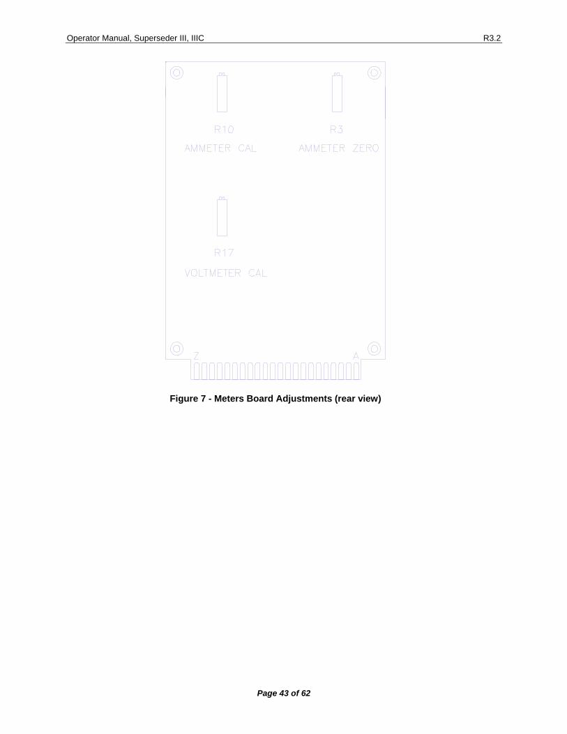
10.2 DIGITAL METERS (see [Figure 7]). NOTE: Digital meters are adjusted by means of multi-turn trimming potentiometers (trimpots) located on the rear (solder side) of the METERS board.
10.2.1. AMMETER
10.2.1.1. NOTE 1: Newer versions of this circuit board no longer have a zero adjustment.
10.2.1.2. NOTE 2: Modified versions of this circuit board may not have a zero adjustment. (not required).
10.2.1.3. ZERO:
• Adjust the zero with R3 for a reading of 00.0 (the exact point is when the + - signs alternate).
10.2.1.4. SCALE:
• This meter has a full scale of 199.9 millivolts to read a 100 AMP shunt with an output of one millivolt per AMP.
• Verify and calibrate using an external ammeter with digital readout. Adjust R10 at a minimum of 25.0A for a reading within ±0.1A of the reference ammeter.
Operator Manual, Superseder III, IIIC R3.2
Page 42 of 62
• NOTE 3: Insert an external shunt/ammeter in series with any of the battery leads (Use the Single Cell adaptor to facilitate the connection or simply use the CAL-100 which is a calibrator designed specifically to test and certify Charger-Analyzer Battery Charger-Analyzers.
• NOTE 4: The charge output current wave is in the form of short pulses (at twice the line frequency). The use of clamp-on meters and moving magnet meters will yield erroneous readings. Verify in discharge (pure DC) if better meters are not available.
10.2.2. VOLTMETER
10.2.2.1. ZERO: No zero adjustments
10.2.2.2. SCALE:
• This meter has a full scale of 1.999 volts, but an attenuator on the board converts it to a full scale of 1.999, 19.99 or 199.9 volts, as selected by the DPM selector switch.
• Verify and calibrate using a voltage source (Power Supply or CAL-100, as a battery voltage simulator) between 10 and 20 volts in the "EXTERNAL 20V" position.
• Adjust R17 for a reading within " 0.01V of the reference voltmeter. • NOTE: individual scales cannot be adjusted.
Operator Manual, Superseder III, IIIC R3.2
Page 43 of 62
Figure 7 - Meters Board Adjustments (rear view)
Operator Manual, Superseder III, IIIC R3.2
Page 44 of 62
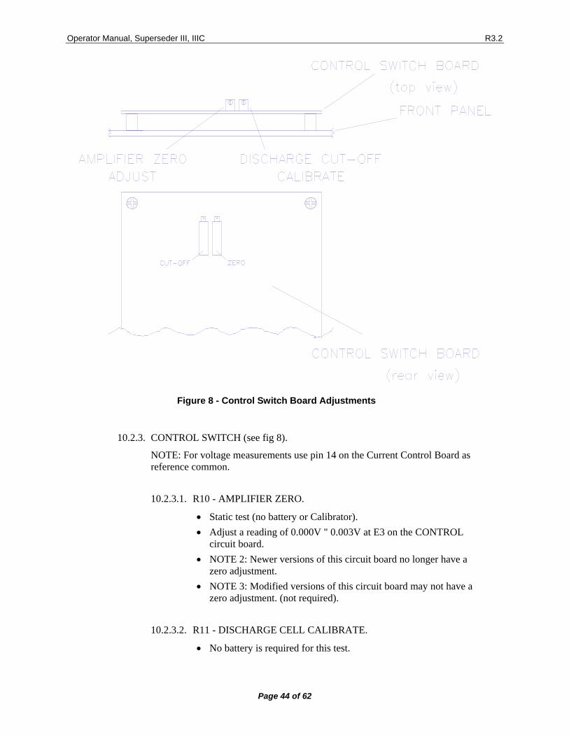
Figure 8 - Control Switch Board Adjustments
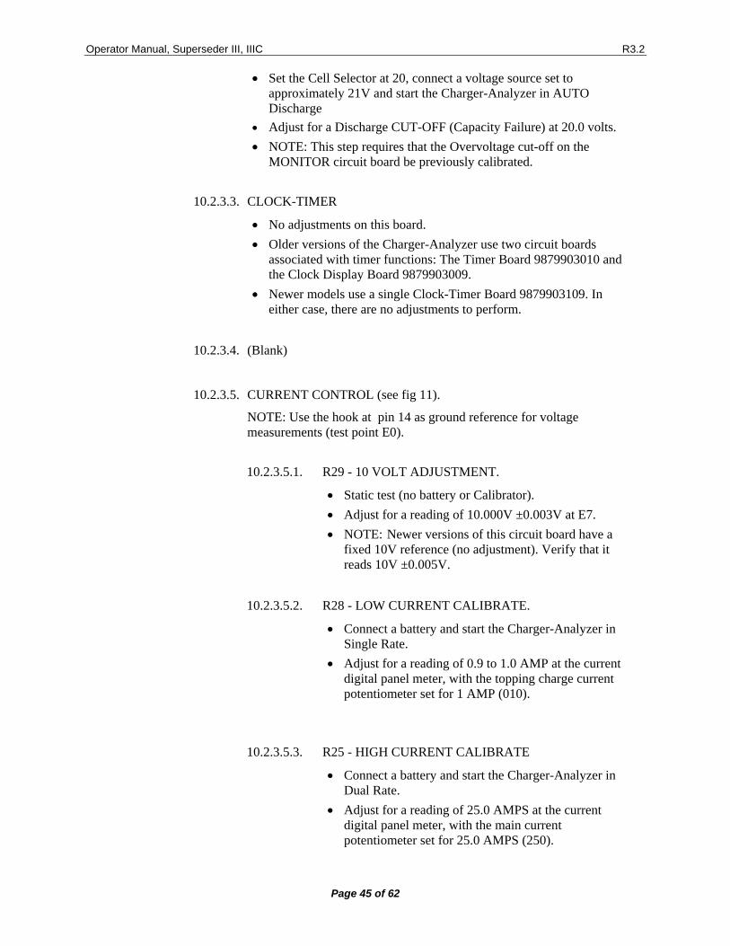
10.2.3. CONTROL SWITCH (see fig 8).
NOTE: For voltage measurements use pin 14 on the Current Control Board as reference common.
10.2.3.1. R10 - AMPLIFIER ZERO.
• Static test (no battery or Calibrator). • Adjust a reading of 0.000V " 0.003V at E3 on the CONTROL
circuit board. • NOTE 2: Newer versions of this circuit board no longer have a
zero adjustment. • NOTE 3: Modified versions of this circuit board may not have a
zero adjustment. (not required).
10.2.3.2. R11 - DISCHARGE CELL CALIBRATE.
• No battery is required for this test.
Operator Manual, Superseder III, IIIC R3.2
Page 45 of 62
• Set the Cell Selector at 20, connect a voltage source set to approximately 21V and start the Charger-Analyzer in AUTO Discharge
• Adjust for a Discharge CUT-OFF (Capacity Failure) at 20.0 volts. • NOTE: This step requires that the Overvoltage cut-off on the
MONITOR circuit board be previously calibrated.
10.2.3.3. CLOCK-TIMER
• No adjustments on this board. • Older versions of the Charger-Analyzer use two circuit boards
associated with timer functions: The Timer Board 9879903010 and the Clock Display Board 9879903009.
• Newer models use a single Clock-Timer Board 9879903109. In either case, there are no adjustments to perform.
10.2.3.4. (Blank)
10.2.3.5. CURRENT CONTROL (see fig 11).
NOTE: Use the hook at pin 14 as ground reference for voltage measurements (test point E0).
10.2.3.5.1. R29 - 10 VOLT ADJUSTMENT.
• Static test (no battery or Calibrator). • Adjust for a reading of 10.000V ±0.003V at E7. • NOTE: Newer versions of this circuit board have a
fixed 10V reference (no adjustment). Verify that it reads 10V ±0.005V.
10.2.3.5.2. R28 - LOW CURRENT CALIBRATE.
• Connect a battery and start the Charger-Analyzer in Single Rate.
• Adjust for a reading of 0.9 to 1.0 AMP at the current digital panel meter, with the topping charge current potentiometer set for 1 AMP (010).
10.2.3.5.3. R25 - HIGH CURRENT CALIBRATE
• Connect a battery and start the Charger-Analyzer in Dual Rate.
• Adjust for a reading of 25.0 AMPS at the current digital panel meter, with the main current potentiometer set for 25.0 AMPS (250).
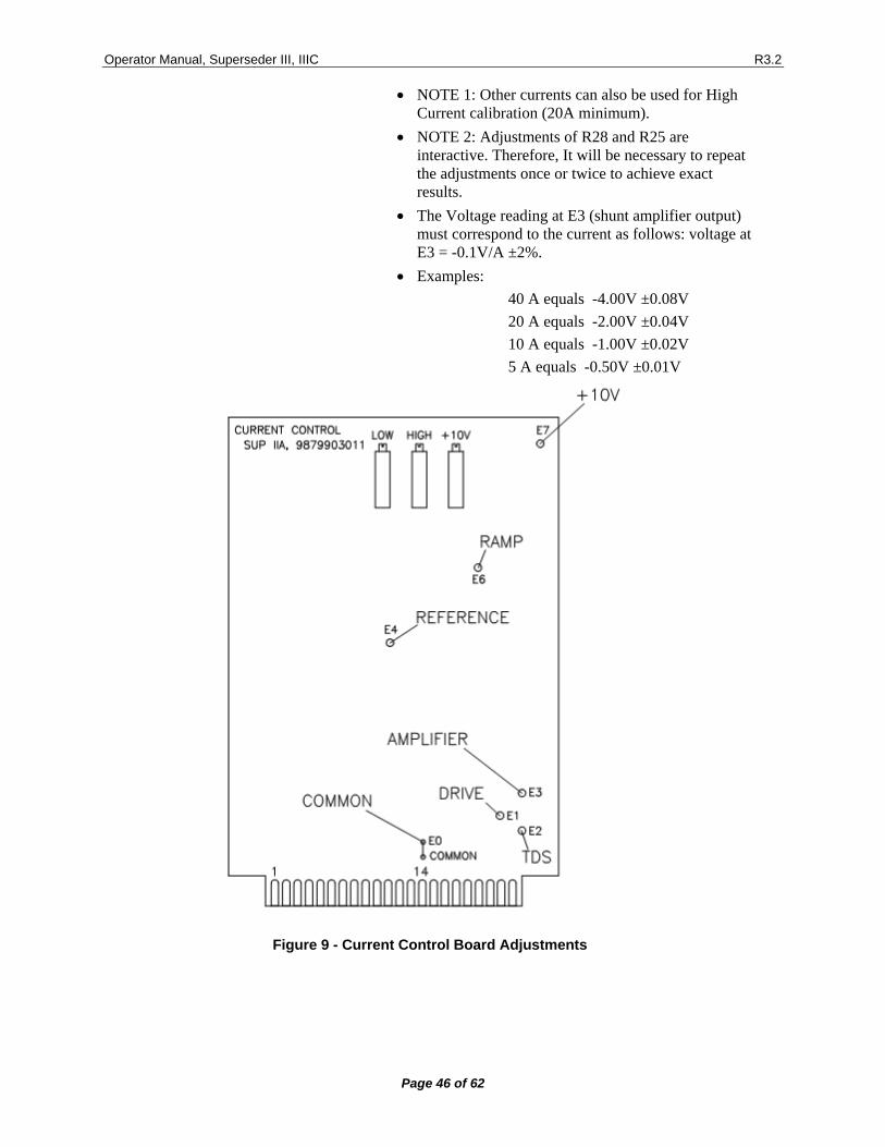
Operator Manual, Superseder III, IIIC R3.2
Page 46 of 62
• NOTE 1: Other currents can also be used for High Current calibration (20A minimum).
• NOTE 2: Adjustments of R28 and R25 are interactive. Therefore, It will be necessary to repeat the adjustments once or twice to achieve exact results.
• The Voltage reading at E3 (shunt amplifier output) must correspond to the current as follows: voltage at E3 = -0.1V/A ±2%.
• Examples: 40 A equals -4.00V ±0.08V 20 A equals -2.00V ±0.04V 10 A equals -1.00V ±0.02V 5 A equals -0.50V ±0.01V
Figure 9 - Current Control Board Adjustments
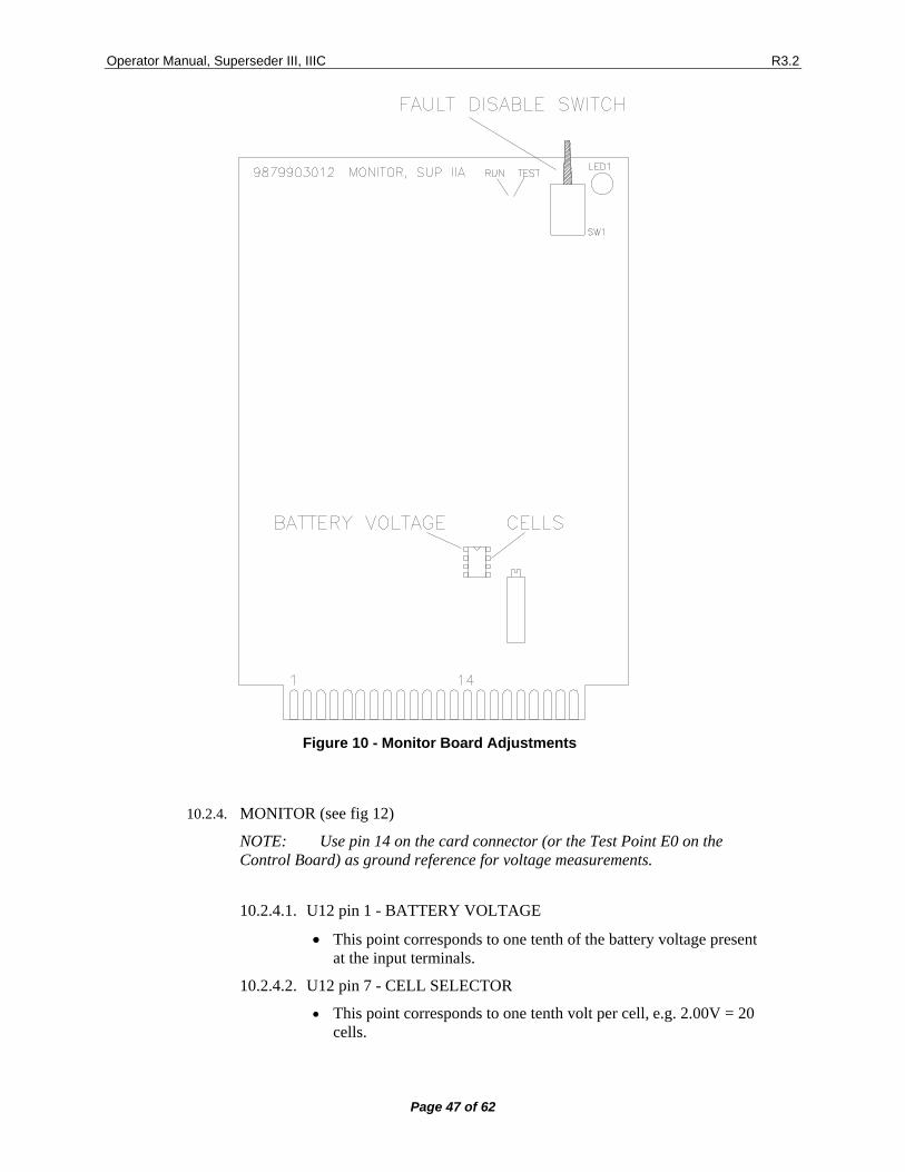
Operator Manual, Superseder III, IIIC R3.2
Page 47 of 62
Figure 10 - Monitor Board Adjustments
10.2.4. MONITOR (see fig 12)
NOTE: Use pin 14 on the card connector (or the Test Point E0 on the Control Board) as ground reference for voltage measurements.
10.2.4.1. U12 pin 1 - BATTERY VOLTAGE
• This point corresponds to one tenth of the battery voltage present at the input terminals.
10.2.4.2. U12 pin 7 - CELL SELECTOR
• This point corresponds to one tenth volt per cell, e.g. 2.00V = 20 cells.
Operator Manual, Superseder III, IIIC R3.2
Page 48 of 62
10.2.4.3. R62 – OVERVOLTAGE
• (no battery) • Set the Current Selectors to zero and set the Cell Selector to 20
(1.75V/cell) • Connect an external voltage source (Power Supply or CAL-100) to
simulate the battery voltage, set at approximately 34V. • Start the Charger-Analyzer in either of the Charge modes and
adjust this trimpot for an Overvoltage charge cut-off at 35.0V ±0.1V.
10.2.5. POWER
There are no adjustments in the Power circuit board, but the following voltages must be measured at the card edge connection fingers (bottom), using a standard digital voltmeter referenced to pin 14.
10.2.5.1. PIN # * VOLTAGE
• 10 to 11 * 36VAC (" 2V nominal, line dependent). • NOTE: 10 to 14 or 11 to 14 will read ½ the total voltage (18V,
nominal). • 12 * 12V"B" (11.4V "0.6V). • NOTE: This is a battery backed-up source. During a power failure,
the voltage will drop to the backup battery voltage minus 0.6V (approximately 7.8V for a 7 cell battery or 9.0V for an 8 cell battery).
• 13 * COMMON (not chassis ground or battery negative!). • 14 * COMMON (not chassis ground or battery negative!). • 15 * +15V (+15.0V "0.75). • 16 * -15V (-15.0V "0.75). • 17 * 9V Battery (8.4V to 9.6, nominal for 7 or 8 cell batteries
respectively). • 18 * 18V (17V +1, -2V nominal, line dependent). • 21 * Timing pulse, twice the line frequency and about 11V and
1ms duration (will read 1.2V +0.1V, -0.2V with a DC meter) • 22 * 12V"A" (11.4 "0.6V).
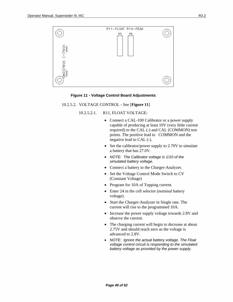
Operator Manual, Superseder III, IIIC R3.2
Page 49 of 62
Figure 11 - Voltage Control Board Adjustments
10.2.5.2. VOLTAGE CONTROL - See [Figure 11]
10.2.5.2.1. R11, FLOAT VOLTAGE:
• Connect a CAL-100 Calibrator or a power supply capable of producing at least 10V (very little current required) to the CAL (-) and CAL (COMMON) test points. The positive lead to COMMON and the negative lead to CAL (-).
• Set the calibrator/power supply to 2.70V to simulate a battery that has 27.0V.
• NOTE: The Calibrator voltage is 1/10 of the simulated battery voltage.
• Connect a battery to the Charger-Analyzer. • Set the Voltage Control Mode Switch to CV
(Constant Voltage) • Program for 10A of Topping current. • Enter 24 in the cell selector (nominal battery
voltage). • Start the Charger-Analyzer in Single rate. The
current will rise to the programmed 10A. • Increase the power supply voltage towards 2.8V and
observe the current. • The charging current will begin to decrease at about
2.75V and should reach zero as the voltage is advanced to 2.8V.
• NOTE: Ignore the actual battery voltage. The Float voltage control circuit is responding to the simulated battery voltage as provided by the power supply.
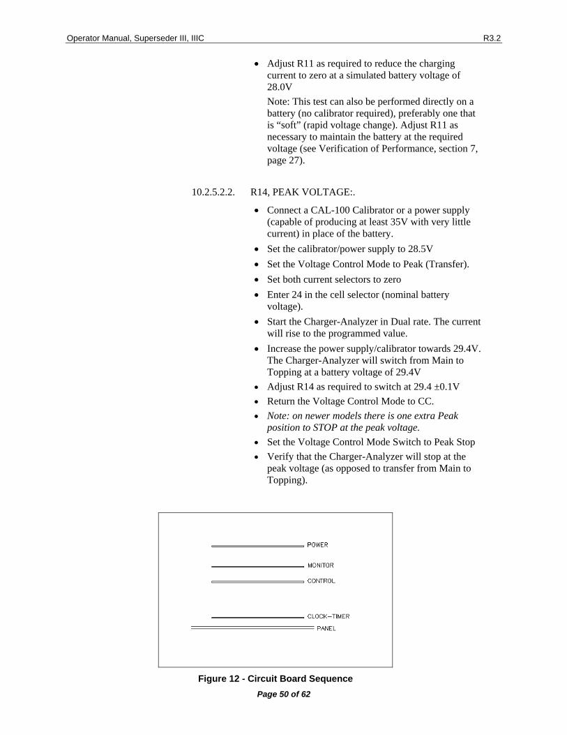
Operator Manual, Superseder III, IIIC R3.2
Page 50 of 62
• Adjust R11 as required to reduce the charging current to zero at a simulated battery voltage of 28.0V Note: This test can also be performed directly on a battery (no calibrator required), preferably one that is “soft” (rapid voltage change). Adjust R11 as necessary to maintain the battery at the required voltage (see Verification of Performance, section 7, page 27).
10.2.5.2.2. R14, PEAK VOLTAGE:.
• Connect a CAL-100 Calibrator or a power supply (capable of producing at least 35V with very little current) in place of the battery.
• Set the calibrator/power supply to 28.5V • Set the Voltage Control Mode to Peak (Transfer). • Set both current selectors to zero • Enter 24 in the cell selector (nominal battery
voltage). • Start the Charger-Analyzer in Dual rate. The current
will rise to the programmed value. • Increase the power supply/calibrator towards 29.4V.
The Charger-Analyzer will switch from Main to Topping at a battery voltage of 29.4V
• Adjust R14 as required to switch at 29.4 ±0.1V • Return the Voltage Control Mode to CC. • Note: on newer models there is one extra Peak
position to STOP at the peak voltage. • Set the Voltage Control Mode Switch to Peak Stop • Verify that the Charger-Analyzer will stop at the
peak voltage (as opposed to transfer from Main to Topping).
Figure 12 - Circuit Board Sequence
Operator Manual, Superseder III, IIIC R3.2
Page 51 of 62
11. TROUBLESHOOTING AND REPAIRS
11.1 TROUBLESHOOTING The following are hints and directions to help you locate the most probable causes of deviation of performance as established in the procedures of section 8.
11.1.1. UNIT CHARGES ON MAIN BUT DOES NOT CHARGE ON TOPPING AND DOES NOT DISCHARGE.
Defective Topping/Discharge current selector or defective Control board.
11.1.2. UNIT CHARGES PROPERLY ONE BATTERY BUT CANNOT CHARGE TWO BATTERIES AT HIGH RATES.
Low line voltage.
11.1.3. UNIT GOES INTO VOLTAGE FAULT IMMEDIATELY OR SHORTLY AFTER STARTING UP (charge mode).
Open link or one or more cells developing a high voltage.
11.1.4. UNIT DISCHARGES CORRECTLY ONE BATTERY BUT RESULTS IN A CURRENT FAULT WHEN DISCHARGING TWO BATTERIES.
Attempting to discharge more than 20A on a battery with more than 28V or defective Monitor board.
11.1.5. THE UNIT CHARGES LOW CURRENT (BELOW 10 AMPS) PROPERLY BUT HUMS NOTICEABLY AT HIGHER CURRENTS.
One of the SCR's is inoperative, or one of the rectifiers is open.
11.1.6. UNIT CHARGES ON TOPPING AND DISCHARGES CORRECTLY BUT WILL NOT CHARGE IN MAIN.
Defective Main Current Selector or defective Control board.
11.1.7. UNIT STARTS IN THE DISCHARGE MODE BUT GOES INTO CAPACITY FAILURE IMMEDIATELY.
Battery not properly connected. Open link. Open cable.
11.1.8. THE DISCHARGE CURRENT LIMITER OPENS THE MOMENT A BATTERY IS CONNECTED TO THE CHARGER.
Shorted discharge transistors(s).
11.1.9. BURNED RESISTOR(S) IN THE DISCHARGE HEATSINK(S).
Transistor(s) shorted and discharge current limiter did not open (wrong limiter value or type).
11.1.10. RESET INDICATOR AND TIMER DISPLAY DO NOT TURN ON.
Open fuse to electronics card rack or problems with the Power circuit board or the transformer feeding it.
11.1.11. DIGITAL VOLTMETER REGISTERS A VOLTAGE (APPROXIMATELY 36 VOLTS) WITH THE UNIT IN RESET AND THE BATTERY IS NOT CONNECTED.
One or both SCR'S shorted. Do not connect a battery under this condition!
Operator Manual, Superseder III, IIIC R3.2
Page 52 of 62
11.1.12. 9.1.12 CURRENT TRACKING IS OFF BY A SMALL CONSTANT AMOUNT.
Amplifier zero or low current calibrate out of adjustment (CONTROL board).
11.1.13. 9.1.13 CURRENT TRACKING IS OFF BY A SMALL AMOUNT WHICH INCREASES AS THE PROGRAMMED VALUE IS INCREASED.
High current calibrate out of adjustment (CONTROL board).
11.1.14. 9.1.15 THE UNIT STARTS BUT EXHIBITS A CURRENT FAULT AFTER SOME TIME (from a few seconds to a few minutes).
a) Current tracking is off, exceeding 1 AMP: Verify Control board calibration. See 8.2.5 and 8.2.2. b) Current tracking is proper: Verify that the shunt amplifier in the Control board reads properly. See 8.2.5 and 8.2.2.
11.1.15. FAULT LIGHT(S) ON AND NO AUDIBLE ALARM. UNIT RUNS NORMALLY.
• Switch in the Monitor board is set in the test position. • If the switch is in the correct position (run), turn power off and back on to
clear the condition and resume operation without resetting.
11.1.16. DIGITAL METERS DO NOT TURN ON.
Open fuse to digital panel meters.
11.1.17. OPEN LIMITER, SMALL CRACK.
Inconsequential opening. Replace and resume operation.
11.1.18. OPEN LIMITER, BLOWN ELEMENT (vaporized).
• Discharge transistors short. • Perform test per 9.2.
11.1.19. CURRENT FAULT IN CV.
• Attempting to charge a battery with a voltage higher than the programmed float voltage.
• Attempting to discharge a battery with a voltage lower than the float voltage.
11.1.20. VOLTAGE FAULT IN CV OR PEAK.
Attempting to discharge a battery with a voltage grater than the float voltage.
11.1.21. IMMEDIATE TRANSFER TO TOPPING IN PEAK.
Attempting to charge a battery with a voltage higher than the programmed peak voltage.
11.1.22. IMMEDIATE STOPPPING IN PEAK.
Attempting to charge a battery with a voltage higher than the programmed peak voltage.
Operator Manual, Superseder III, IIIC R3.2
Page 53 of 62
11.2 FINDING A SHORTED DISCHARGE TRANSISTOR Since all discharge transistors are wired in parallel, a single shorted transistor will short the entire bank. The procedure that follows will allow the finding of the shorted transistor without requiring removal and testing of each device individually.
11.2.1. EQUIPMENT REQUIRED
• Digital Voltmeter. • Battery, 24V. • Lamp, 24V (lamp must draw at least 0.5 A).
11.2.2. PROCEDURE
11.2.2.1. TURN UNIT OFF, DISCONNECT IT FROM THE WALL OUTLET.
11.2.2.2. Connect the lamp in place of the discharge current limiter (see fig 8).
11.2.2.3. Connect the charger to the battery.
11.2.2.4. If the lamp illuminates, it indicates that there is a short in the discharge circuit, generated by one or more shorted transistors.
11.2.2.5. Measure the voltage across the individual .22 OHM emitter resistors (RED-RED-GOLD-GOLD) (see fig 8).
• A non zero reading, approximately 0.1V for a lamp drawing .5A, indicates current flow due to a transistor with a collector to emitter short.
• NOTE: A non zero reading on all emitter resistors (0.02V approx for a lamp drawing 0.5A) indicates a different failure mode (collector to base short; refer to step 7).
11.2.2.6. Remove any shorted transistors and repeat steps 4 and 5 until a no short reading is obtained. Replace defective devices only with transistor type MJ15023.
11.2.2.7. If all transistors appear to be shorted (ALL emitter resistors reading a voltage), then, one or more have failed with a collector to base short, causing the remainder of the transistors to turn on. It will then be necessary to check each transistor individually.
• This can be greatly facilitated by searching for a zero reading. This will indicate the shorted device.
11.2.2.8. When replacing transistors, make sure that the base and emitter pins engage properly in the socket contacts. Add heat sink compound and torque the screws properly to insure a good thermal transfer.
• NOTE: If replacing any of the control transistors (Q1 and Q2), note that they are mounted with a mica insulator.
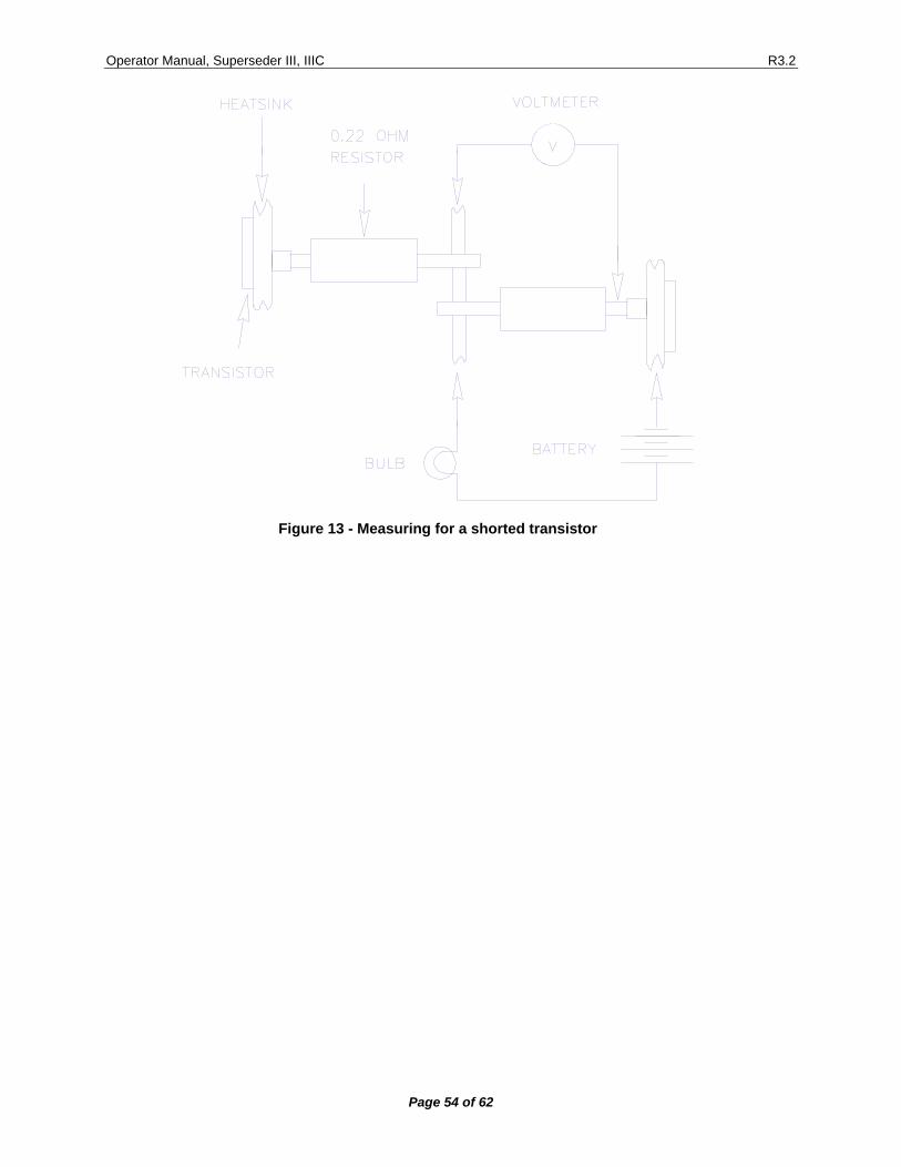
Operator Manual, Superseder III, IIIC R3.2
Page 54 of 62
Figure 13 - Measuring for a shorted transistor
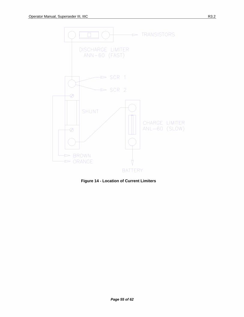
Operator Manual, Superseder III, IIIC R3.2
Page 55 of 62
Figure 14 - Location of Current Limiters
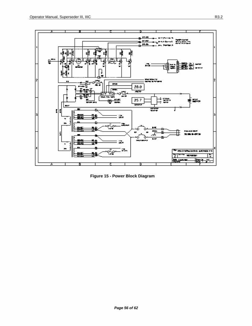
Operator Manual, Superseder III, IIIC R3.2
Page 56 of 62
Figure 15 - Power Block Diagram
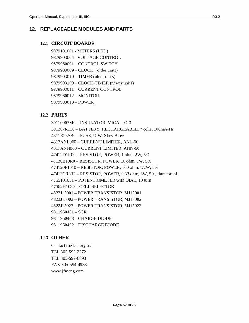
Operator Manual, Superseder III, IIIC R3.2
Page 57 of 62
12. REPLACEABLE MODULES AND PARTS
12.1 CIRCUIT BOARDS
9879101001 - METERS (LED) 9879903004 - VOLTAGE CONTROL 9879960001 – CONTROL SWITCH 9879903009 – CLOCK (older units) 9879903010 – TIMER (older units) 9879903109 – CLOCK-TIMER (newer units) 9879903011 – CURRENT CONTROL 9879960012 – MONITOR 9879903013 – POWER
12.2 PARTS
30110003M0 – INSULATOR, MICA, TO-3 391207R110 – BATTERY, RECHARGEABLE, 7 cells, 100mA-Hr 4311R25SB0 – FUSE, ¼ W, Slow Blow 4317ANL060 – CURRENT LIMITER, ANL-60 4317ANN060 – CURRENT LIMITER, ANN-60 47412D1R00 – RESISTOR, POWER, 1 ohm, 2W, 5% 47130E10R0 – RESISTOR, POWER, 10 ohm, 1W, 5% 474120F1010 – RESISTOR, POWER, 100 ohm, 1/2W, 5% 47413CR33F – RESISTOR, POWER, 0.33 ohm, 3W, 5%, flameproof 4755101031 – POTENTIOMETER with DIAL, 10 turn 47562H1030 – CELL SELECTOR 4822J15001 – POWER TRANSISTOR, MJ15001 4822J15002 – POWER TRANSISTOR, MJ15002 4822J15023 – POWER TRANSISTOR, MJ15023 9811960461 – SCR 9811960463 – CHARGE DIODE 9811960462 – DISCHARGE DIODE
12.3 OTHER
Contact the factory at: TEL 305-592-2272 TEL 305-599-6893 FAX 305-594-4933 www.jfmeng.com
Operator Manual, Superseder III, IIIC R3.2
Page 58 of 62
13. BATTERY TESTING NOTES
Note, hazardous condition: Handle batteries with extreme care as they are capable of very high discharge rates if short circuited. Check the Battery Manual, IMM or Aircraft Manufacturer Instructions for information on charging, discharging and testing. The Charge & Float and the Charge & Peak Stop modes are particularly useful with lead acid batteries, where the battery voltage is a better indicator of the state of charge, as compared with Nickel-Cadmium batteries where terminal voltage gives little information on the state of charge. Lead-Acid batteries are normally float charged (constant voltage) typically at 2.3V/cell. A 6 cell pack (12V) will then be float charged with the voltage selector at 13.8V. In this mode, the charge current is set to the highest level that the cells will safely take (typically up to 1C depending on the battery type and specific manufacturer instructions). This will be the charge current until the float voltage is reached, at which time the current will diminish to the level needed to maintain the float voltage. Lead-Acid batteries can also be charged in a manner in which it is possible to know much better the end of charge. When a Lead-Acid cell is charged with constant current at C/15 to C/10, the end voltage will rise rapidly at about 90 to 95% of charge, which occurs at about 2.4 to 2.45V/cell. A 5A-hr, 6 cell pack, can be charged at 335mA to 500mA, with the voltage selector at 14.7V. The CHARGER-ANALYZER will stop the charge operation when the rapid rise of end-of-charge voltage is detected. For Nickel-Cadmium batteries, the most effective charge method is constant current vs time. In the absence of any particular instructions from the manufacturer, charging at c/10 for 12 to 16 hours will insure a complete charge. The Nickel-Cadmium batteries can also be charged in the float mode, with a voltage of 1.4 V/cell (a 20 cell battery would be set to 28.0V).
NOTE: Prolonged use of the float (constant voltage) method on Nickel-Cadmium batteries will result in cell imbalance, which could eventually lead to premature cell failure due to un-even charge acceptance and un-even discharge capacity.
Operator Manual, Superseder III, IIIC R3.2
Page 59 of 62
14. DISCLAIMER
14.1 This Charger-Analyzer is a precision instrument intended to be operated by personnel qualified in the servicing of aircraft, industrial or medical batteries.
14.2 JFM Engineering’s responsibility is limited to the repair/replacement of any malfunctioning part of the system (not responsible for any losses incurred from the usage of the system).
14.3 User’s Responsibility • It is the user’s responsibility to verify suitability in the intended application.
• It is the user’s responsibility to verify the performance of the instruments and to operate and maintain it in accordance with the above given instructions.
• It is the user’s responsibility to test batteries in accordance to the instructions and recommendations of the manufacturers of the batteries.
• It is the user’s responsibility to operate the Instrument within standard safety procedures applicable to the operation of a Battery Test Facility.
• It is the user’s responsibility to install power receptacles and wiring in accordance with local wiring codes.
• It is the user’s responsibility to observe all necessary precautions and to be equipped with personal protective equipment when working with batteries to avoid injury due to electrolyte splashing, short circuits with tools and to avoid injury due to the size and weight of the batteries.
• It is the user’s responsibility to verify the integrity of the performance of this instrument in accordance with the instructions of Section 8.
• It is the user’s responsibility to operate this instrument within the limits and guidelines as described in the Precautions and Installation sections 6.7 and 7.0
• It is the user’s responsibility to properly package the instrument for shipping whenever factory service is required.
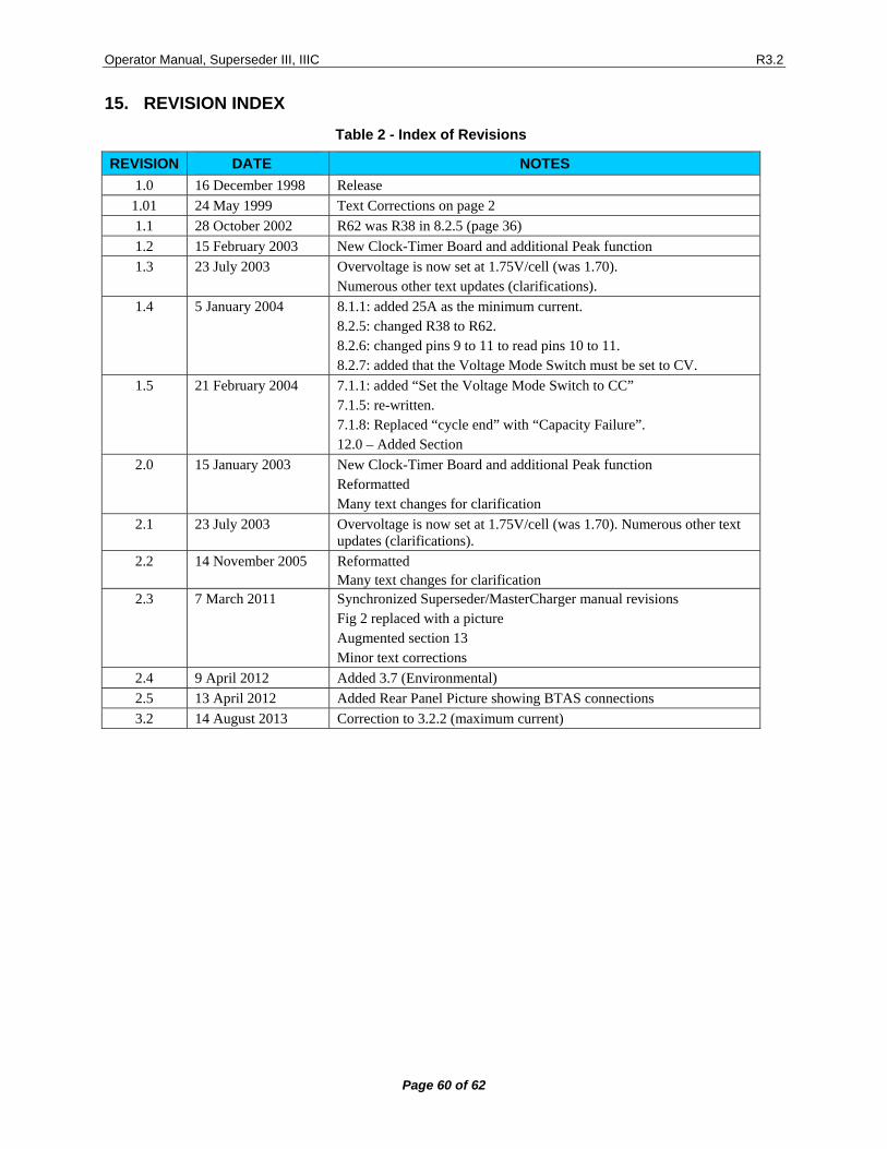
Operator Manual, Superseder III, IIIC R3.2
Page 60 of 62
15. REVISION INDEX
Table 2 - Index of Revisions
REVISION DATE NOTES 1.0 16 December 1998 Release
1.01 24 May 1999 Text Corrections on page 2 1.1 28 October 2002 R62 was R38 in 8.2.5 (page 36) 1.2 15 February 2003 New Clock-Timer Board and additional Peak function 1.3 23 July 2003 Overvoltage is now set at 1.75V/cell (was 1.70).
Numerous other text updates (clarifications). 1.4 5 January 2004 8.1.1: added 25A as the minimum current.
8.2.5: changed R38 to R62. 8.2.6: changed pins 9 to 11 to read pins 10 to 11. 8.2.7: added that the Voltage Mode Switch must be set to CV.
1.5 21 February 2004 7.1.1: added “Set the Voltage Mode Switch to CC” 7.1.5: re-written. 7.1.8: Replaced “cycle end” with “Capacity Failure”. 12.0 – Added Section
2.0 15 January 2003 New Clock-Timer Board and additional Peak function Reformatted Many text changes for clarification
2.1 23 July 2003 Overvoltage is now set at 1.75V/cell (was 1.70). Numerous other text updates (clarifications).
2.2 14 November 2005 Reformatted Many text changes for clarification
2.3 7 March 2011 Synchronized Superseder/MasterCharger manual revisions Fig 2 replaced with a picture Augmented section 13 Minor text corrections
2.4 9 April 2012 Added 3.7 (Environmental) 2.5 13 April 2012 Added Rear Panel Picture showing BTAS connections 3.2 14 August 2013 Correction to 3.2.2 (maximum current)

Operator Manual, Superseder III, IIIC R3.2
Page 61 of 62
Blank Page

Operator Manual, Superseder III, IIIC R3.2
Page 62 of 62
Blank Page