Embed Size (px)
Citation preview
Seminar Report on Gyrobus 2012-2013
Dept. Of Electrical & Electronics Engg. G.P.T.C, Muttom
INTRODUCTION
A Gyrobus is an electric bus that uses flywheel energy storage, not overhead
wires like a trolleybus. The name comes from the Greek language term for
flywheel, gyros. While there are no gyrobuses currently in use commercially,
development in this area continues.
A gyrobus is a special bus which does not use a normal engine. It has a big
flywheel of steel or other materials (weighing about one ton) rotating at very high
speed (RPM). By rotating at such high speed, the flywheel stores large amounts of
kinetic energy. This big wheel moves the wheels of the bus. At special stations,
electric engines accelerate the flywheel so the bus can still run. There are not many
buses of this kind because they are very expensive
Seminar Report on Gyrobus 2012-2013
Dept. Of Electrical & Electronics Engg. G.P.T.C, Muttom
DEVELOPMENT
The concept of a flywheel-powered bus was developed and brought to
fruition during the 1940s by Oerlikon (of Switzerland), with the intention of
creating an alternative to battery-electric buses for quieter, lower-frequency routes,
where full overhead-wire electrification could not be justified.
Rather than carrying an internal combustion engine or batteries, or
connecting to overhead powerlines, a gyrobus carries a large flywheel that is spun
at up to 3,000 RPM by a "squirrel cage" motor.[1]
Power for charging the flywheel
was sourced by means of three booms mounted on the vehicle's roof, which
contacted charging points located as required or where appropriate (at passenger
stops en route, or at terminals, for instance). To obtain tractive power, capacitors
would excite the flywheel's charging motor so that it became a generator, in this
way transforming the energy stored in the flywheel back into electricity. Vehicle
braking was electric, and some of the energy was recycled back into the flywheel,
thereby extending its range.
Fully charged, a gyrobus could typically travel as far as 6km on a level route
at speeds of up to 50 to 60 km/h, depending on vehicle batch (load), as top speeds
varied from batch to batch. The installation in Yverdon-les-Bains (Switzerland)
Seminar Report on Gyrobus 2012-2013
Dept. Of Electrical & Electronics Engg. G.P.T.C, Muttom
sometimes saw vehicles needing to travel as far as 10 km on one charge, although
it is not known how well they performed towards the upper end of that distance.
Charging a flywheel took between 30 seconds and 3 minutes; in an effort to
reduce the charge time, the supply voltage was increased from 380 volts to 500
volts. Given the relatively restricted range between charges, it is likely that several
charging stops would have been required on longer routes, or in dense urban
traffic. It is not clear whether vehicles that require such frequent delays would have
been practical and/or suitable for modern-day service applications.
The demonstrator was first displayed (and used) publicly in summer 1950
and, to promote the system, this vehicle continued to be used for short periods of
public service in a myriad of locations at least until 1954.
In 1979, General Electric was awarded a $5 million four-year contract by the
United States government, the Department of Energy and the Department of
Transportation, to develop a prototype flywheel bus.
In the 1980s, Volvo briefly experimented with using flywheels charged by a
small Diesel engine and recharged via braking energy. This was eventually
dumped in favour of using hydraulic accumulators. During the 1990s, CCM had
developed a flywheel for both mobile and stationary applications.
Seminar Report on Gyrobus 2012-2013
Dept. Of Electrical & Electronics Engg. G.P.T.C, Muttom
In 2005, the Center for Transportation and the Environment, working with
the University of Texas at Austin, Center for Electromechanics, Test Devices, Inc.,
and DRS Technologies sought funding for the development of a prototype
gyrobus.
Seminar Report on Gyrobus 2012-2013
Dept. Of Electrical & Electronics Engg. G.P.T.C, Muttom
EARLY COMMERCIAL SERVICE
The first full commercial service began in October 1953, linking the Swiss
communities of Yverdon-les-Bains and Grandson. However, this was a route with
limited traffic potential, and although technically successful it was not
commercially viable. Services ended in late October 1960, and neither of the two
vehicles (nor the demonstrator) survived.
The next system to open was in Léopoldville in Belgian Congo (currently
Kinshasa in the Democratic Republic of the Congo). Here there were 12 vehicles
(although apparently some reports suggest 17), which operated over four routes,
with recharging facilities being provided about every 2 km. These were the largest
of the gyrobuses, being 10.4 m in length, weighing 10.9 tonnes, carrying up to 90
passengers, and having a maximum speed of 60 km/h (about 37 mph).
There were major problems related to excessive "wear and tear". One
significant reason for this was that drivers often took shortcuts across unpaved
roads, which after rains became nothing more than quagmires. Other problems
included breakage of gyro ball bearings, and high humidity resulting in traction
motor overload. The system's demise, however, came because of high energy
consumption. The bus operator deemed that 3.4 kWh/km per gyrobus was
Seminar Report on Gyrobus 2012-2013
Dept. Of Electrical & Electronics Engg. G.P.T.C, Muttom
unaffordable, so closure came in the summer of 1959 with the gyrobuses being
abandoned.
The third location to use gyrobuses commercially was Ghent, Belgium.
Three gyrobuses started operation in late summer 1956 on a route linking Ghent
and Merelbeke (the route Gent Zuid - Merelbeke). The flywheel was in the center
of the bus, spanning almost the whole width of the vehicle, and having a vertical
axis of rotation.
The Ghent - Merelbeke route was intended to be the first of a proposed
multi-route network. Instead its Gyrobuses stayed in service for only three years,
being withdrawn late autumn 1959. The operator considered them unreliable,
"spending more time off the road than on", and that their weight damaged road
surfaces. They were also considered to be energy hungry, consuming 2.9
kWh/km—compared with between 2.0 kWh/km and 2.4 kWh/km for trams with
much greater capacity.
One of Ghent's gyrobuses has been preserved and restored, and is displayed
at the VLATAM-museum in Antwerp. It is sometimes shown (and used to carry
passengers) at Belgian exhibitions, transport enthusiasts' bazaars, etc. The tram
depot in Merelbeke has been closed since 1998, but it still stands, as it is protected
by the law.
Seminar Report on Gyrobus 2012-2013
Dept. Of Electrical & Electronics Engg. G.P.T.C, Muttom
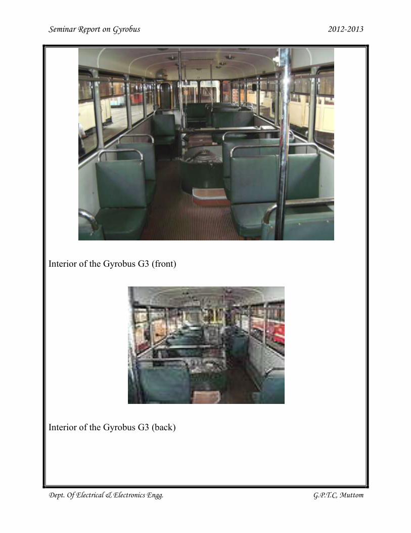
Interior of the Gyrobus G3 (front)
Interior of the Gyrobus G3 (back)
Seminar Report on Gyrobus 2012-2013
Dept. Of Electrical & Electronics Engg. G.P.T.C, Muttom
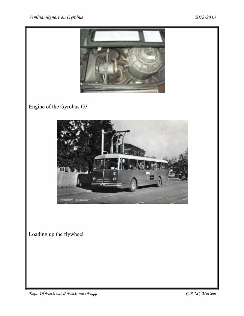
Engine of the Gyrobus G3
Loading up the flywheel
Seminar Report on Gyrobus 2012-2013
Dept. Of Electrical & Electronics Engg. G.P.T.C, Muttom
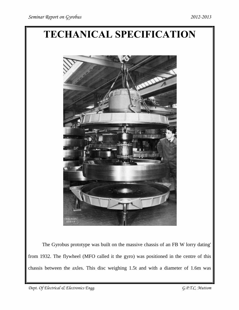
TECHANICAL SPECIFICATION
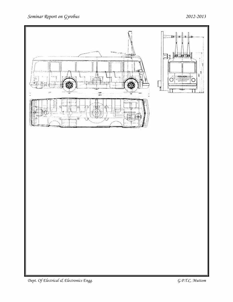
The Gyrobus prototype was built on the massive chassis of an FB W lorry dating'
from 1932. The flywheel (MFO called it the gyro) was positioned in the centre of this
chassis between the axles. This disc weighing 1.5t and with a diameter of 1.6m was
Seminar Report on Gyrobus 2012-2013
Dept. Of Electrical & Electronics Engg. G.P.T.C, Muttom
enclosed in an airtight chamber filled with hydrogen gas at a reduced pressure of 0.7 bar
to lower "air" resistance. The flywheel would spin at a maximum of 3000rpm.
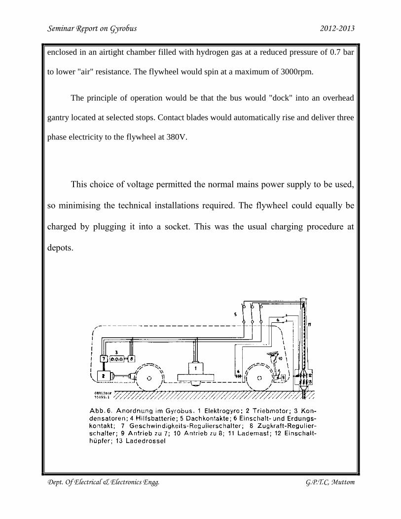
The principle of operation would be that the bus would "dock" into an overhead
gantry located at selected stops. Contact blades would automatically rise and deliver three
phase electricity to the flywheel at 380V.
This choice of voltage permitted the normal mains power supply to be used,
so minimising the technical installations required. The flywheel could equally be
charged by plugging it into a socket. This was the usual charging procedure at
depots.
Seminar Report on Gyrobus 2012-2013
Dept. Of Electrical & Electronics Engg. G.P.T.C, Muttom
The flywheel was spun up with a three-phase asynchronous motor. The same
motor acted as a generator when disconnected from the ground supply. The choice
of an asynchronous brushless machine helped reduce friction within the flywheel
assembly to an absolute minimum. Once in generator mode, power from the
flywheel would be fed to the 52kW asynchronous traction motor, which was
arranged longitudinally behind the rear axle. Capacitors controlled the motor
torque. The arrangement could be reversed, with energy recovered by the motor during
braking or on downhill runs being fed back to the flywheel.
In normal operation the flywheel could slow down from its initial 3000 rpm to
2100 rpm. In emergencies the speed could further be reduced to 1500 rpm, but this would
negatively affect the performance of the vehicle. Below this speed a proper functioning of
the transmission could no longer be guaranteed. Under normal conditions, the Gyrobus
could cover 5 to 6km between charges (taking stops and traffic into account). A charge
would then take two to five minutes. In idle mode, the fywheel could continue spinning
for more than ten hours. The bus would, however, be plugged in at the depot overnight to
keep the flywheel at 2850 rpm. This was done to permit a quick start in the morning and
also because a full recharge would have posed a heavy load on the grid, A recharge from
standstill could take 40 minutes. The bus could run at up to 55
Seminar Report on Gyrobus 2012-2013
Dept. Of Electrical & Electronics Engg. G.P.T.C, Muttom
Seminar Report on Gyrobus 2012-2013
Dept. Of Electrical & Electronics Engg. G.P.T.C, Muttom
TYPES OF GYROBUS
YVERDON
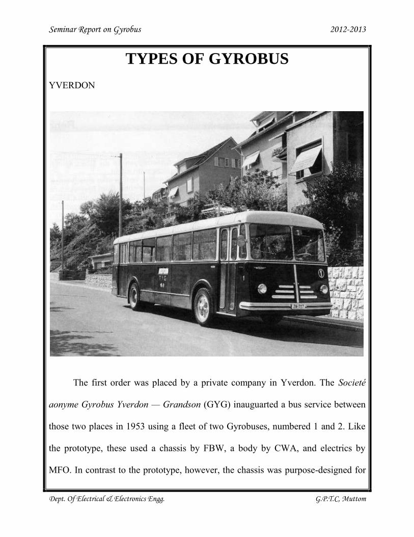
The first order was placed by a private company in Yverdon. The Societé
aonyme Gyrobus Yverdon — Grandson (GYG) inauguarted a bus service between
those two places in 1953 using a fleet of two Gyrobuses, numbered 1 and 2. Like
the prototype, these used a chassis by FBW, a body by CWA, and electrics by
MFO. In contrast to the prototype, however, the chassis was purpose-designed for
Seminar Report on Gyrobus 2012-2013
Dept. Of Electrical & Electronics Engg. G.P.T.C, Muttom
Gyrobus use, and weight savings were achieved. In keeping with the times, an
angular body style was adopted. The route was 4.5km long and had four recharging
points. In order to speed-up the charging process, the charging voltage was raised
from 380V to 500V in 1954. The small fleet was joined by the prototype that year,
with the new arrival being numbered 3.
The extremely light loadings of the route caused financial difficulties and led
to service cuts. Rather than turing the company's fortunes around, these led to even
greater difficulties. The high electricity consumption and other costs led GYG to
replace its Gyrobuses by diesel minibuses in 1960.
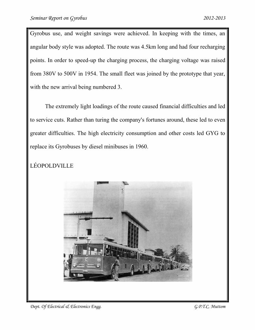
LÉOPOLDVILLE
Seminar Report on Gyrobus 2012-2013
Dept. Of Electrical & Electronics Engg. G.P.T.C, Muttom
The next order came from Léopoldville in the Belgian Congo (today
Kinshasa in D.R. Congo). The 12 buses ordered were largely similar to those of
Yverdon and were numbered 101-112. The operator, Société: des transports en
commun de Léopoldville (TCL) used them on a four-route system of about 20km,
making it the largest Gyrobus system ever operated. However poor operating
conditions and the tendency for drivers to deviate from the official routes and drive
on rough unmade roads lead to heavy wear and tear. Consequently, TCL made
generous use of its warranty rights with MFO to obtain spare parts. The outbreak
of war in 1959 finally put an end to Gyrobus operations in Léopoldville.
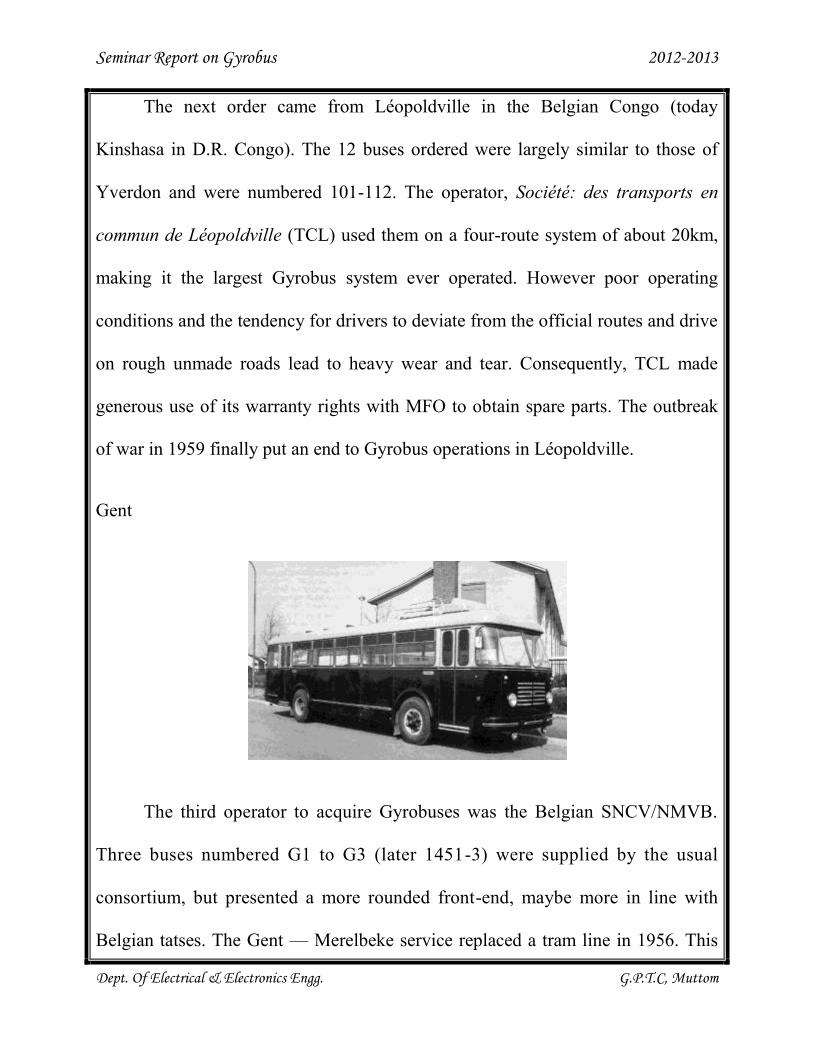
Gent
The third operator to acquire Gyrobuses was the Belgian SNCV/NMVB.
Three buses numbered G1 to G3 (later 1451-3) were supplied by the usual
consortium, but presented a more rounded front-end, maybe more in line with
Belgian tatses. The Gent — Merelbeke service replaced a tram line in 1956. This
Seminar Report on Gyrobus 2012-2013
Dept. Of Electrical & Electronics Engg. G.P.T.C, Muttom
line was and remained an island operation. It was especially the high costs of
electricity that led to abandonment in 1959. One vehicle has survived and is
preserved in the tram museum in Antwerpen. This vehicle, the only know Gyrobus
survivor, visited Yverdon in 2003 to mark the 50th anniversary of that system.
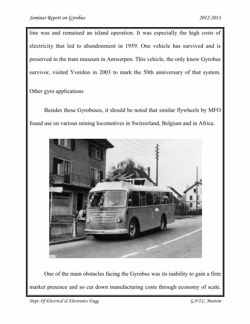
Other gyro applications
Besides these Gyrobuses, it should be noted that similar flywheels by MFO
found use on various mining locomotives in Switzerland, Belgium and in Africa.
One of the main obstacles facing the Gyrobus was its inability to gain a firm
market presence and so cut down manufacturing costs through economy of scale.
Seminar Report on Gyrobus 2012-2013
Dept. Of Electrical & Electronics Engg. G.P.T.C, Muttom
A further recurring issue was the high cost of electricity (or shall we say low cost
of fuel). Furthermore, the manufacturers would appear to have been unfortunate in
their choice of pilot projects, with many of the problems being external rather than
strictly technical. Not necessarily a disadvantage but certainly a point worth noting
was the dynamic behaviour of the vehicle. The spinning flywheel acts like a giant
gyroscope and so resists changes in orientation. This had to be taken into account
be the driver and so induced an adapted driving technique. At the same time, this
gyroscope effect led to a very smooth ride. As reduced comfort through eratic
driving is precisely an argument that is often used against buses, this is certainly
something worth looking into
In today's environment, many of the factors that disadvantaged the Gyrobus
have changed. Fuel prices are rising and concerns over pollution and smog have
led to experiments with such inefficient and dangerous storage technologies as
hydrogen cells (which appear to be more in political favour than technologically
sound). Would a simpler, safer and more comfortable alternative not do the same
in a friendlier manner? Modern power electronics would help reduce power
consumption whilst also enabling faster charging. Modern materials could help
reduce the overall weight of the bus while retaining the required robustness. Maybe
the Gyrobus is far from dead.
Seminar Report on Gyrobus 2012-2013
Dept. Of Electrical & Electronics Engg. G.P.T.C, Muttom
ADVANTAGES
"Pollution-free" (Pollution confined to generators on electric power grid.)
Runs without rails (An advantage because the route can be varied at will.)
Can operate flexibly at varying distances
Seminar Report on Gyrobus 2012-2013
Dept. Of Electrical & Electronics Engg. G.P.T.C, Muttom
DISADVANTAGES
Weight: a bus which can carry 20 persons and has a range of 20 km requires
a flywheel weighing three tonnes.
The flywheel, which turns at 3000 revolutions per minute, requires special
attachment and security—because the external speed of the disk is 900 km/h.
Driving a gyrobus has the added complexity that the flywheel acts as a
gyroscope that will resist changes in orientation, for example when a bus
tilts while making a turn, assuming that the flywheel has a horizontal
rotation axis.
Seminar Report on Gyrobus 2012-2013
Dept. Of Electrical & Electronics Engg. G.P.T.C, Muttom
FURTHER DEVELOPMENTS
After the Gyrobus was discontinued in all locations, there have been a
number of attempts to make the concept work. Recently, there have been two
successful projects, though the original idea of storing energy has been changed
considerably: In Dresden, Germany there is the "Autotram", a vehicle that looks
like a modern tram, but moves on a flat surface, not on tracks. It has run since 2005
and is powered by a flywheel, though the wheel is small and only used to store
energy from braking. The main source of energy is a fuel cell. The second
successful vehicle was the Capabus, which ran at the Expo 2010 in Shanghai. It
was charged with electricity at the stops - just like the Gyrobus was. However,
instead of using a flywheel for energy storage the Capabus utilized capacitors.
Seminar Report on Gyrobus 2012-2013
Dept. Of Electrical & Electronics Engg. G.P.T.C, Muttom
CONCLUSION
Since 1955 there have been some practical applications of electrogyrobuses.
Such buses are equipped with a flywheel unit consisting of an asynchronous motor
and generator coupled to a flywheel and of electric traction motors. The unwinding
of the flywheel of an electrogyrobus is accomplished with the aid of an electric
motor. The stored kinetic energy is sufficient for traveling a distance of 4-5 km.
The efficiency of an electrogyrobus is not better than 50 percent. The weight-to-
work ratio of the flywheel unit is 322 kg/kWh (32 times greater than that of the
currently used electrochemical current sources). The unit operational expenses of
an electrogyrobus are 5 percent greater than those of a trolleybus and 20 percent
greater than those of an autobus. Experimental electrogyrobuses have been
operated on some interurban runs, for instance, between Ghent and Merelbeke
(Belgium). The electrogyrobus is an auxiliary means of passenger transport on
short runs; it is also usable in transporting dangerously explosive objects.
Seminar Report on Gyrobus 2012-2013
Dept. Of Electrical & Electronics Engg. G.P.T.C, Muttom
REFERENCES
"the GYROBUS: Something New Under the Sun?". Motor Trend: p. p37.
January 1952.
Access to Energy Newsletter, Archive Volume: Volume 7, Issue/No.: Vol. 7,
No. 8, Date: April 01, 1980 03:23 PM, Title: Anniversary of the Grand
Disaster, Article: The Flywheel Bus is Back
Center View (CTE) Spring 2005
Seminar Report on Gyrobus 2012-2013
Dept. Of Electrical & Electronics Engg. G.P.T.C, Muttom
CONTENTS
Introduction : 01
Development : 02
Early commercial service : 05
Techanical specification : 09
Types of gyrobus : 13
Advantages : 18
Disadvantages : 19
Further developments : 20
Conclusion : 21
References : 22
Seminar Report on Gyrobus 2012-2013
Dept. Of Electrical & Electronics Engg. G.P.T.C, Muttom
ABSTRACT
Since 1955 there have been some practical applications of
electrogyrobuses. Such buses are equipped with a flywheel unit
consisting of an asynchronous motor and generator coupled to a
flywheel and of electric traction motors. The unwinding of the flywheel
of an electrogyrobus is accomplished with the aid of an electric motor.
The stored kinetic energy is sufficient for traveling a distance of 4–5 km.
The efficiency of an electrogyrobus is not better than 50 percent. The
weight-to-work ratio of the flywheel unit is 322 kg/kWh (32 times
greater than that of the currently used electrochemical current sources).
The unit operational expenses of an electrogyrobus are 5 percent greater
than those of a trolleybus and 20 percent greater than those of an
autobus. Experimental electrogyrobuses have been operated on some
interurban runs, for instance, between Ghent and Merelbeke (Belgium).
The electrogyrobus is an auxiliary means of passenger transport on short
runs; it is also usable in transporting dangerously explosive objects.