Embed Size (px)
Citation preview
Introduction 2 BASIC Stamp®
Microcontrollers
•Microcontrollers can be thought of as very small computers which may be programmed to control systems such as cell phones, microwave ovens, toys, automotive systems, etc.
•The BASIC Stamps are hybrid microcontrollers which are designed to be programmed in a version of the BASIC
programming language called PBASIC.
•Hardware support on the module allows fast, easy programming and use.
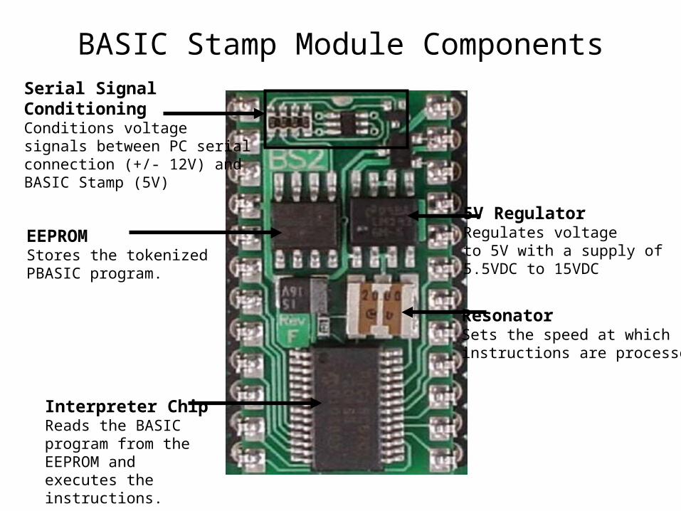
BASIC Stamp Module Components
5V RegulatorRegulates voltageto 5V with a supply of 5.5VDC to 15VDC
ResonatorSets the speed at whichinstructions are processed.
EEPROMStores the tokenized PBASIC program.
Interpreter ChipReads the BASIC program from the EEPROM and executes the instructions.
Serial SignalConditioningConditions voltagesignals between PC serialconnection (+/- 12V) and BASIC Stamp (5V)
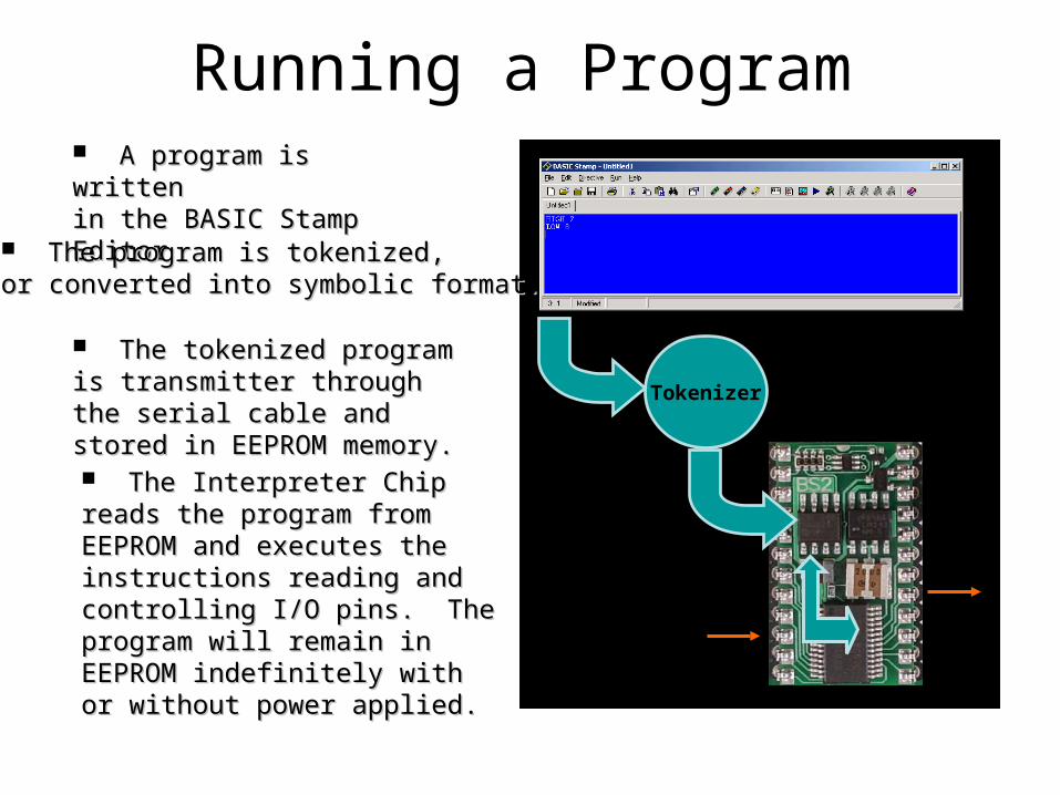
Running a Program A program is writtenA program is writtenin the BASIC Stamp Editorin the BASIC Stamp Editor
The Interpreter Chip reads the The Interpreter Chip reads the program from EEPROM and program from EEPROM and executes the instructions reading executes the instructions reading and controlling I/O pins. The and controlling I/O pins. The program will remain in EEPROM program will remain in EEPROM indefinitely with or without power indefinitely with or without power applied.applied.
The program is tokenized,The program is tokenized,or converted into symbolic format.or converted into symbolic format.
Tokenizer
The tokenized program is The tokenized program is transmitter through the serial cable transmitter through the serial cable and stored in EEPROM memory.and stored in EEPROM memory.
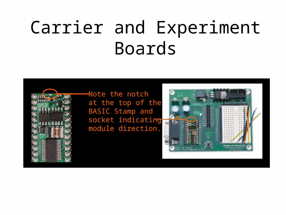
Carrier and Experiment Boards
Note the notchNote the notchat the top of theat the top of theBASIC Stamp andBASIC Stamp andsocket indicatingsocket indicatingmodule direction.module direction.
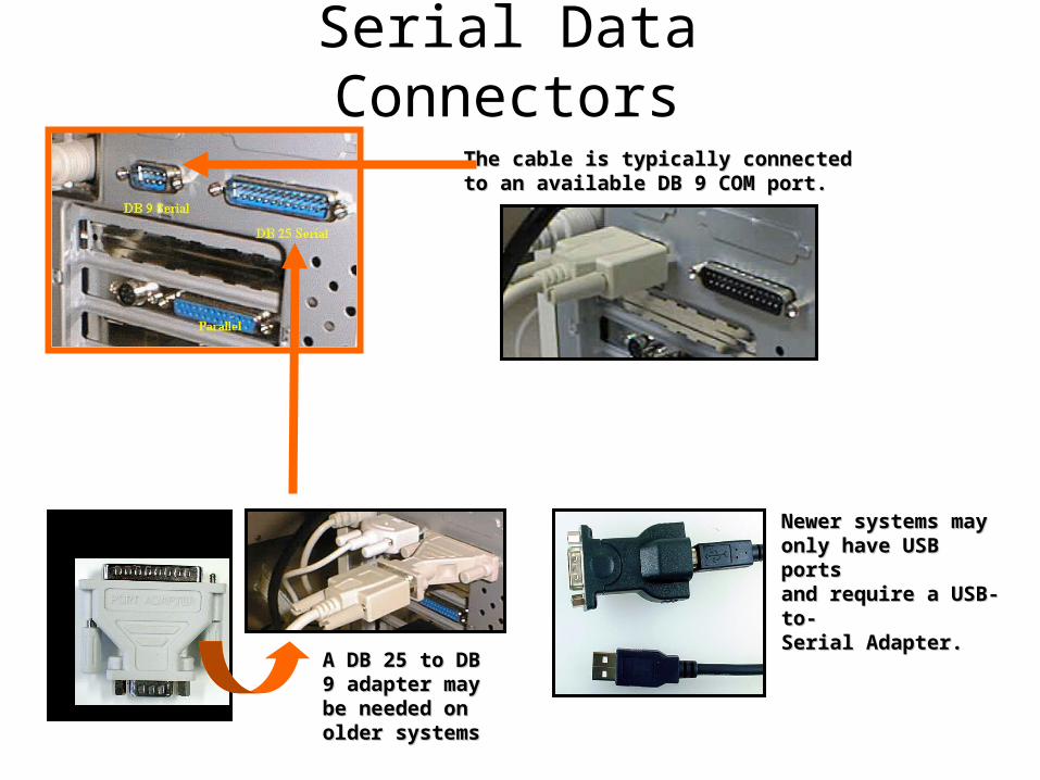
Serial Data Connectors
The cable is typically connectedThe cable is typically connectedto an available DB 9 COM port.to an available DB 9 COM port.
A DB 25 to DB 9 A DB 25 to DB 9 adapter may adapter may be needed on be needed on older systemsolder systems
Newer systems mayNewer systems mayonly have USB portsonly have USB portsand require a USB-to-and require a USB-to-Serial Adapter.Serial Adapter.
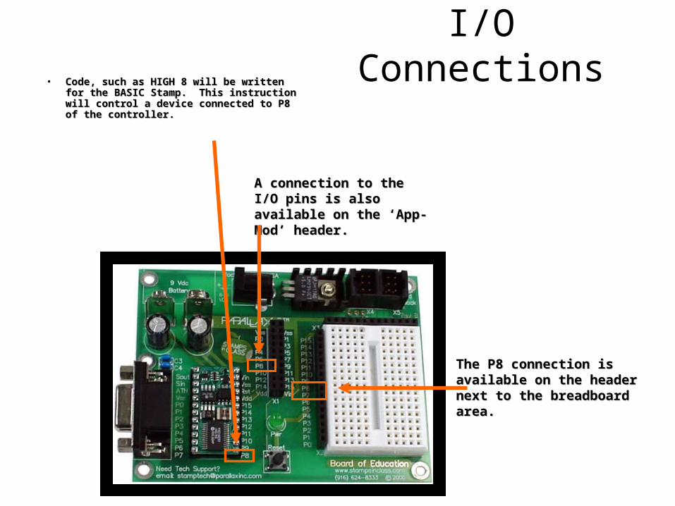
I/O Connections• Code, such as HIGH 8 will be written for the Code, such as HIGH 8 will be written for the
BASIC Stamp. This instruction will control BASIC Stamp. This instruction will control a device connected to P8 of the controller.a device connected to P8 of the controller.
The P8 connection isThe P8 connection isavailable on the headeravailable on the headernext to the breadboard next to the breadboard area.area.
A connection to the I/O pins A connection to the I/O pins is also available on the is also available on the ‘App-Mod’ header.‘App-Mod’ header.
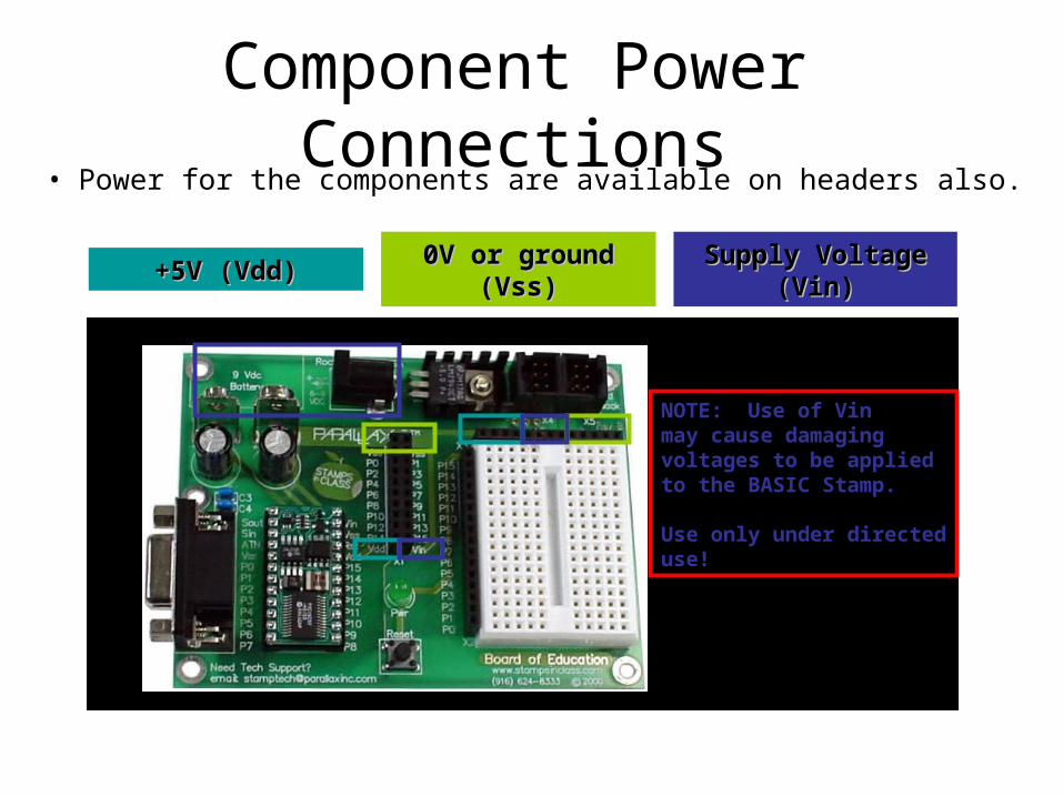
Component Power Connections• Power for the components are available on headers also.
+5V (Vdd)+5V (Vdd) 0V or ground (Vss)0V or ground (Vss) Supply Voltage (Vin)Supply Voltage (Vin)
NOTE: Use of Vinmay cause damagingvoltages to be applied to the BASIC Stamp.
Use only under directeduse!
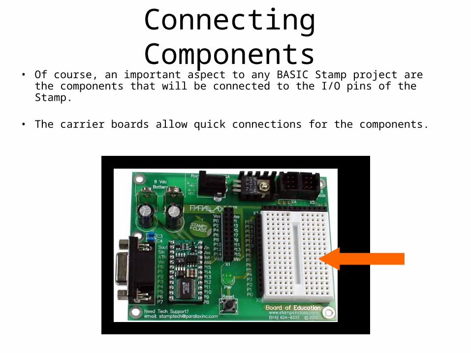
Connecting Components• Of course, an important aspect to any BASIC Stamp project are the
components that will be connected to the I/O pins of the Stamp.
• The carrier boards allow quick connections for the components.
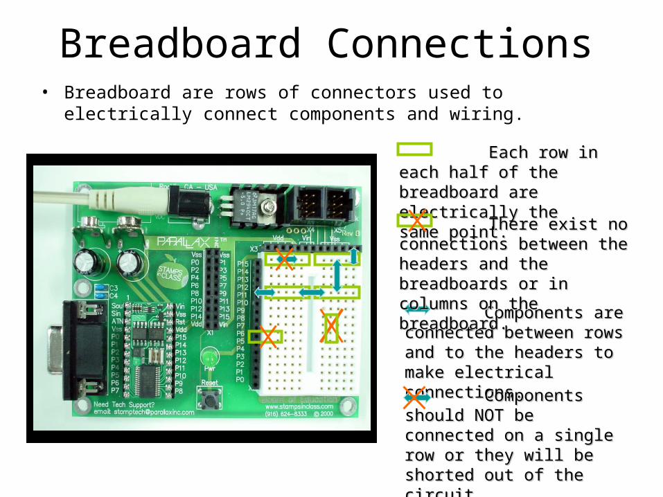
Breadboard Connections• Breadboard are rows of connectors used to electrically connect
components and wiring.
Each row in each half Each row in each half of the breadboard are of the breadboard are electrically the same point.electrically the same point.
Components are Components are connected between rows and to connected between rows and to the headers to make electrical the headers to make electrical connections. connections.
There exist no connections There exist no connections between the headers and the between the headers and the breadboards or in columns on breadboards or in columns on the breadboard.the breadboard.
Components should NOT Components should NOT be connected on a single row be connected on a single row or they will be shorted out of or they will be shorted out of the circuit.the circuit.
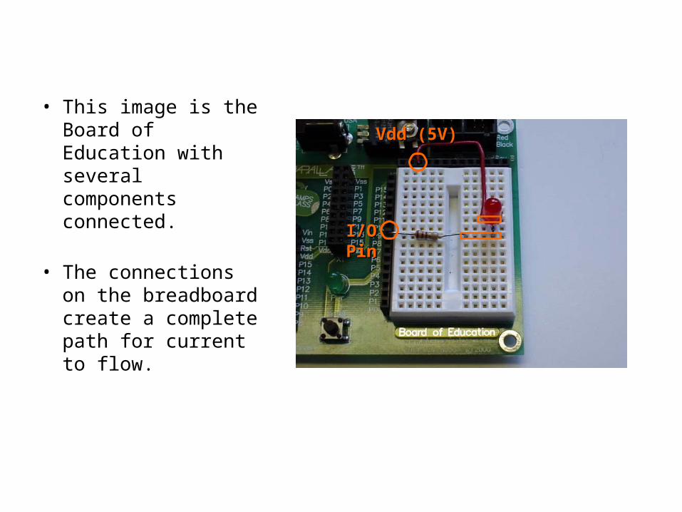
• This image is the Board of Education with several components connected.
• The connectionson the breadboardcreate a completepath for currentto flow.
Vdd (5V)Vdd (5V)
I/OI/OPinPin
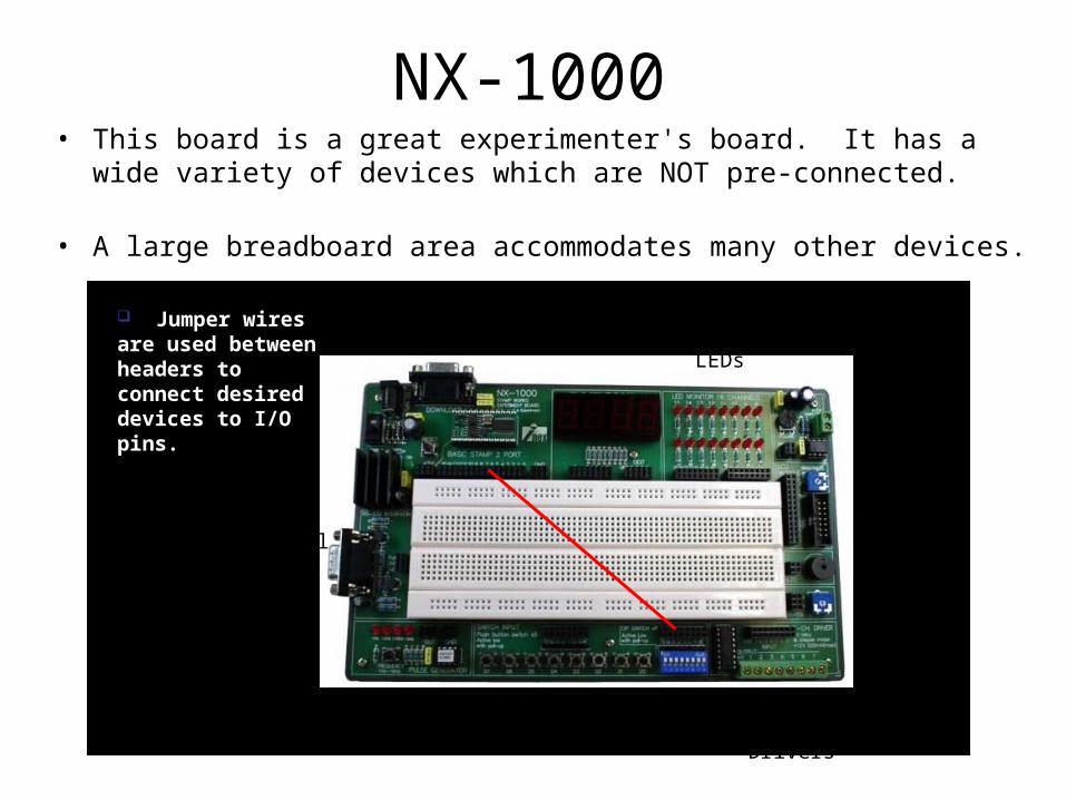
NX-1000• This board is a great experimenter's board. It has a wide variety of
devices which are NOT pre-connected.
• A large breadboard area accommodates many other devices.
7-Segment LED Display
Current-Limited LEDs
AudioAmp
LCDHeader
Speaker& Pot
High-CurrentDrivers
Active-Low switchesSelectableOscillator
Spare SerialConnector
Jumper wires are used between headers to connect desired devices to I/O pins.
ProgrammingSerial Connector