Embed Size (px)
Citation preview

IN02D--01
M17080
N·m (kgf·cm, ft·lbf) : Specified torque
zNon--reusable part
z Crankshaft Front Oil Seal
49 (500,36)
Oil Pump Body
Driven Rotor
Drive Rotor ×10
Relief Valve
Oil Pump Body Cover
Compression Spring
Plug
--INTRODUCTION HOW TO USE THIS MANUALIN--1
HOW TO USE THIS MANUALGENERAL INFORMATION1. INDEXAn INDEX is provided on the first page of each section to guide you to the item to be repaired. To assist youin finding your way through the manual, the Section Title and major heading are given at the top of everypage.2. GENERAL DESCRIPTIONAt the beginning of each section, a General Description is given that pertains to all repair operations con-tained in that section.Read these precautions before starting any repair task.3. TROUBLESHOOTINGTROUBLESHOOTING tables are included for each system to help you diagnose the problem and find thecause. The fundamentals of how to proceed with troubleshooting are described on page IN--8.Be sure to read this before performing troubleshooting.4. PREPARATIONPreparation lists the SST (Special Service Tools), recommended tools, equipment, lubricant and SSM (Spe-cial Service Materials) which should be prepared before beginning the operation and explains the purposeof each one.5. REPAIR PROCEDURESMost repair operations begin with an overview illustration. It identifies the components and shows how theparts fit together.Example:

Illustration:what to do and where
21. CHECKPISTONSTROKEOFOVERDRIVEBRAKE
(a) PlaceSSTandadial indicator onto theoverdrive brakepiston as shown in the illustration.
Task heading : what to do
SST 09350--30020 (09350--06120)
Set part No. Component part No.
Detailed text : how to do task
(b) Measure the strokeapplyingand releasing the compressed
Piston stroke: 1.40— 1.70mm (0.0551—0.0669 in.)Specification
air (392 -- 785 kPa, 4 -- 8 kgf.cm2 or 57 -- 114 psi) asshown in the illustration.
IN--2--INTRODUCTION HOW TO USE THIS MANUAL
The procedures are presented in a step--by--step format:S The illustration shows what to do and where to do it.S The task heading tells what to do.S The detailed text tells how to perform the task and gives other information such as specifications
and warnings.Example:
This format provides the experienced technician with a FAST TRACK to the information needed. The uppercase task heading can be read at a glance when necessary, and the text below it provides detailed informa-tion. Important specifications and warnings always stand out in bold type.6. REFERENCESReferences have been kept to a minimum. However, when they are required you are given the page to referto.7. SPECIFICATIONSSpecifications are presented in bold type throughout the text where needed. You never have to leave theprocedure to look up your specifications. They are also found in Service Specifications section, for quickreference.8. CAUTIONS, NOTICES, HINTS:S CAUTIONS are presented in bold type, and indicate there is a possibility of injury to you or other
people.S NOTICES are also presented in bold type, and indicate the possibility of damage to the components
being repaired.S HINTS are separated from the text but do not appear in bold. They provide additional information to
help you perform the repair efficiently.9. SI UNITThe UNITS given in this manual are primarily expressed according to the SI UNIT (International System ofUnit), and alternately expressed in the metric system and in the English System.Example:
Torque: 30 N·m (310 kgf·cm, 22 ft·lbf)

IN05L--01
M01548
M1UZ Engine
--INTRODUCTION IDENTIFICATION INFORMATIONIN--3
IDENTIFICATION INFORMATIONENGINE SERIAL NUMBER
1. ENGINE SERIAL NUMBERThe engine serial number is stamped on the engine block, asshown in the illustration.

FI1066
IN05M--01
IN--4--INTRODUCTION REPAIR INSTRUCTIONS
REPAIR INSTRUCTIONSGENERAL INFORMATION1. BASIC REPAIR HINT(a) Use the protection covers to keep the boat clean and pre-
vent damage.(b) During disassembly, keep parts in the appropriate order
to facilitate reassembly.(c) Observe the following:
(1) Before performing electrical work, disconnect thenegative (--) terminal cable from the battery.
(2) If it is necessary to disconnect the battery for in-spection or repair, always disconnect the negative(--) terminal cable which is grounded to the engineblock.
(3) To prevent damage to the battery terminal, loosenthe cable nut and raise the cable straight up withouttwisting or prying it.
(4) Clean the battery terminals and cable ends with aclean shop rag.Do not scrape themwith a file or oth-er abrasive objects.
(5) Install the cable ends to the battery terminals withthe nut loose, and tighten the nut after installation.Do not use a hammer to tap the cable ends onto theterminals.
(6) Be sure the cover for the positive (+) terminal isproperly in place.
(d) Check hose and wiring connectors to make sure that theyare secure and correct.
(e) Non--reusable parts(1) Always replace cotter pins, gaskets, O--rings and oil
seals etc. with new ones.(2) Non--reusable parts are indicated in the component
illustrations by the ”z” symbol.(f) Precoated parts
Precoated parts are bolts and nuts, etc. that are coatedwith a seal lock adhesive at the factory.(1) If a precoated part is retightened, loosened or
caused tomove in any way, it must be recoatedwiththe specified adhesive.
(2) When reusing precoated parts, clean off the oldadhesive and dry with compressed air. Then applythe specified seal lock adhesive to the bolt, nut orthreads.
(3) Precoated parts are indicated in the component il-lustrations by the ”L” symbol.
(g) When necessary, use a sealer on gaskets to preventleaks.

M01367
MediumCurrent Fuse andHighCurrent FuseEqual AmperageRating
AbbreviationPart NameSymbolIllustration
FUSE
CIRCUITBREAKER
FUSE
CB
BE5594
M05598
--INTRODUCTION REPAIR INSTRUCTIONSIN--5
(h) Carefully observe all specifications for bolt tighteningtorques. Always use a torque wrench.
(i) Useof special service tools (SST) and special servicema-terials (SSM) may be required, depending on the natureof the repair. Be sure to use SST and SSM where speci-fied and follow the proper work procedure. A list of SSTand SSM can be found in preparation section in thismanual.
(j) When replacing fuses, be sure the new fuse has the cor-rect amperage rating. DO NOT exceed the rating or useone with a lower rating.
(k) Care must be taken when sling up and supporting the en-gine. Be sure to support the engine at the properpositions(See page IN--7).(1) After the engine is slung up, be sure to support it on
stands. It is extremely dangerous to do any work onengine suspended at the sling hook, even for asmall job that can be finished quickly.
(l) Observe the following precautions to avoid damage to thefollowing parts:(1) Do not open the cover or case of the ECU, ECMun-
less absolutely necessary. (If the IC terminals aretouched, the IC may be destroyed by static electric-ity.)

IN0253
WRONG CORRECT
IN0252
WRONG CORRECT
IN0002
Example
IN--6--INTRODUCTION REPAIR INSTRUCTIONS
(2) To disconnect vacuum hoses, pull on the end, notthe middle of the hose.
(3) To pull apart electrical connectors, pull on the con-nector itself, not the wires.
(4) Be careful not to drop electrical components, suchas sensors or relays. If they are dropped on a hardfloor, they should be replaced and not reused.
(5) When steam cleaning an engine, protect the elec-tronic components, air filter and emissions--relatedcomponents from water.
(6) Never use an impact wrench to remove or installtemperature switches or temperature sensors.
(7) When checking continuity at the wire connector, in-sert the tester probe carefully to prevent terminalsfrom bending.
(8) When using a vacuum gauge, never force the hoseonto a connector that is too large. Use a step--downadapter for adjustment. Once the hose has beenstretched, it may leak.
(m) Tag hoses before disconnecting them:(1) When disconnecting vacuum hoses, use tags to
identify how they should be reconnected.(2) After completing a job, double check that the vacu-
umhoses are properly connected. A label under thehood shows the proper layout.
(n) Unless otherwise stated, all resistance is measured at anambient temperature of 20˚C (68˚F). Because the resist-ance may be outside specification if measured at hightemperatures immediately after the engine has been run-ning measurements should be made when the enginehas cooled down.

IN05N--01
M01930
Front
SLING POSITION
FrontRear
Front Engine HangerRear Engine Hanger
SUPPORT POSITION
FrontRear
Front Engine mounting InsulatorRear Engine mounting Insulator
To level the engine, move up the rear stands 59 mm (2.3 in.) as shownabove figure.
59 mm( 2.3 in.)
HINT:
--INTRODUCTION REPAIR INSTRUCTIONSIN--7
ENGINE SLING AND SUPPORT POSITIONS

IN05Q--01
IN--8 --INTRODUCTION HOW TO TROUBLESHOOT ECU CONTROLLEDSYSTEMS
HOW TO TROUBLESHOOT ECU CONTROLLED SYSTEMSGENERAL INFORMATIONA large number of ECU controlled systems are used in the M1UZ Engine. In general, the ECU controlledsystem is considered to be a very intricate system requiring a high level of technical knowledge and expertskill to troubleshoot. However, the fact is that if you proceed to inspect the circuits one by one, troubleshoot-ing of these systems is not complex. If you have adequate understanding of the system and a basic knowl-edge of electricity, accurate diagnosis and necessary repair can be performed to locate and fix the problem.FOR USING OBDII SCAN TOOL OR TOYOTA HAND--HELD TESTERS Before using the OBDII scan tool or TOYOTA hand--held tester, the OBDII scan tool’s instruction book
or TOYOTA hand--held tester’s operator manual should be read thoroughly.S If theOBDII scan tool or TOYOTA hand--held tester cannot communicate with ECU controlled systems
when you have connected the cable of the OBDII scan tool or TOYOTA hand--held tester to DLC3,Turned the ignition switch ON and operated the scan tool, there is a problem on the engine side or toolside.(1) If communication is normal when the tool is connected to another engine, inspect the diagnosis
data link line (Busline) or ECU power circuit of the engine.(2) If communication is still not possible when the tool is connected to another engine, the problem
is probably in the tool itself, so perform the Self Test procedures outlined in the Tester Operator’sManual.

IN05P--01
Engine/Boat Brought to Workshop
Customer ProblemAnalysis
Symptom Confirmationand Diagnostic TroubleCode Check
Symptom Simulation
Diagnostic TroubleCode Chart
Problem Symptoms Table
Circuit Inspection or PartsInspection
Repair
Confirmation Test
End
1
2
4
3
5
6
7
8
Ask the customer about the conditions and theenvironment when the problem occurred.
1
Confirm the symptoms and the problem conditions,and check the diagnostic trouble codes.(When the problem symptoms do not appearduring confirmation, use the symptom simulationmethod described later on.)
2, 3
Check the results obtained in Step 2, then confirmthe inspection procedure for the system or the partwhich should be checked using the diagnostictrouble code chart or the problem symptoms table.
4, 5, 6
Check and repair the affected system or part inaccordance with the instructions in Step 6.
7
After completing repairs, confirm that the problemhas been eliminated.(If the problem is not reproduced, perform theconfirmation test under the same conditions andin the same environment as when it occurred forthe first time.)
8
--INTRODUCTION HOW TO TROUBLESHOOT ECU CONTROLLEDSYSTEMS
IN--9
HOW TO PROCEED WITH TROUBLESHOOTINGCarry out troubleshooting in accordance with the procedure on the following page. Here, only the basic pro-cedure is shown. Details are provided in the DI section, showing the most effective methods for each circuit.Confirm the troubleshooting procedures first for the relevant circuit before beginning troubleshooting of thatcircuit.

Important Points in the Customer ProblemAnalysis
DWhat ---------- Engine model, system nameDWhen ---------- Date, time, occurrence frequencyDWhere ----------ConditionsD Under what conditions? ---------- Running conditions, driving conditions, weather conditions
D How did it happen? ---------- Problem symptoms
(Sample) Engine control system check sheet.
ENGINE CONTROL SYSTEM Check Sheet
Customer’s Name
Driver’s Name
Data BoatBrought in
License No.
Model and ModelYear
Hull No.
Engine Model
Hourmeter Reading hour
ProblemSym
ptoms
Engine doesnot Start
Difficult toStart
Poor Idling
PoorDrive ability
Engine Stall
Others
Engine does not crank No initial combustion No complete combustion
Engine cranks slowlyOther
Incorrect first idle Idling rpm is abnormal High ( rpm) Low ( rpm)Rough idling Other
Hesitation Back fire Muffler explosion (after--fire) SurgingKnocking Other
Soon after starting After accelerator pedal depressedAfter accelerator pedal released Shifting from N to F or N to ROther
Datas Problem
Constant Sometimes ( times per day/month)
Inspector’sName
CUSTOMER PROBLEM ANALYSIS CHECK
IN--10 --INTRODUCTION HOW TO TROUBLESHOOT ECU CONTROLLEDSYSTEMS
1. CUSTOMER PROBLEM ANALYSISIn troubleshooting, the problem symptoms must be confirmed accurately and all preconceptions must becleared away in order to give an accurate judgment. To ascertain just what the problem symptoms are, it isextremely important to ask the customer about the problem and the conditions at the time it occurred.Important Point in the Problem Analysis:The following 5 items are important points in the problem analysis. Past problems which are thought to beunrelated and the repair history, etc.may also help in some cases, so asmuch information as possible shouldbe gathered and its relationship with the problem symptoms should be correctly ascertained for referencein troubleshooting. A customer problem analysis table is provided in the troubleshooting section for eachsystem for your use.

DIAGNOSTIC TROUBLE CODE CHECK PROCEDURE
Diagnostic TroubleCode Check (Make anote of and then clear)
Confirmationof Symptoms
Diagnostic TroubleCode Check
Problem Condition
Diagnostic TroubleCode Display
Problem symptomsexist
Same diagnostictrouble code isdisplayed
Problem is still occurring in the diagnosticcircuit.
Normal code isdisplayed
The problem is still occurring in a placeother than in the diagnostic circuit.(The diagnostic trouble code displayedfirst is either for a past problem or it is asecondary problem.)
No problemsymptoms exist
The problem occurred in the diagnosticcircuit in the past.
Normal Code Display Problem symptomsexist
Normal code isdisplayed
The problem is still occurring in a placeother than in the diagnostic circuit.
No problemsymptoms exist
Normal code isdisplayed
The problem occurred in a place otherthan in the diagnostic circuit in the past.
--INTRODUCTION HOW TO TROUBLESHOOT ECU CONTROLLEDSYSTEMS
IN--11
2. SYMPTOM CONFIRMATION AND DIAGNOSTIC TROUBLE CODE CHECKThe diagnostic system in the M1UZ engine fulfills various functions. The first function is the DiagnosticTrouble Code Check in which a malfunction in the signal circuits to the ECU is stored in code in the ECUmemory at the time of occurrence, to be output by the technician during troubleshooting. Another functionis the Input Signal Check which checks if the signals from various switches are sent to the ECU correctly.By using these check functions, the problem areas can be narrowed down quickly and troubleshooting canbe performed effectively.In diagnostic trouble code check, it is very important to determinewhether the problem indicated by the diag-nostic trouble code is still occurring or occurred in the past but returned to normal at present. In addition,it must be checked in the problem symptom check whether the malfunction indicated by the diagnostictrouble code is directly related to the problem symptom or not. For this reason, the diagnostic trouble codesshould be checked before and after the symptomconfirmation to determine the current conditions, as shownin the table below. If this is not done, it may, depending on the case, result in unnecessary troubleshootingfor normally operating systems, thus making it more difficult to locate the problem, or in repairs not pertinentto the problem. Therefore, always follow the procedure in correct order and perform the diagnostic troublecode check.
IN--12 --INTRODUCTION HOW TO TROUBLESHOOT ECU CONTROLLEDSYSTEMS
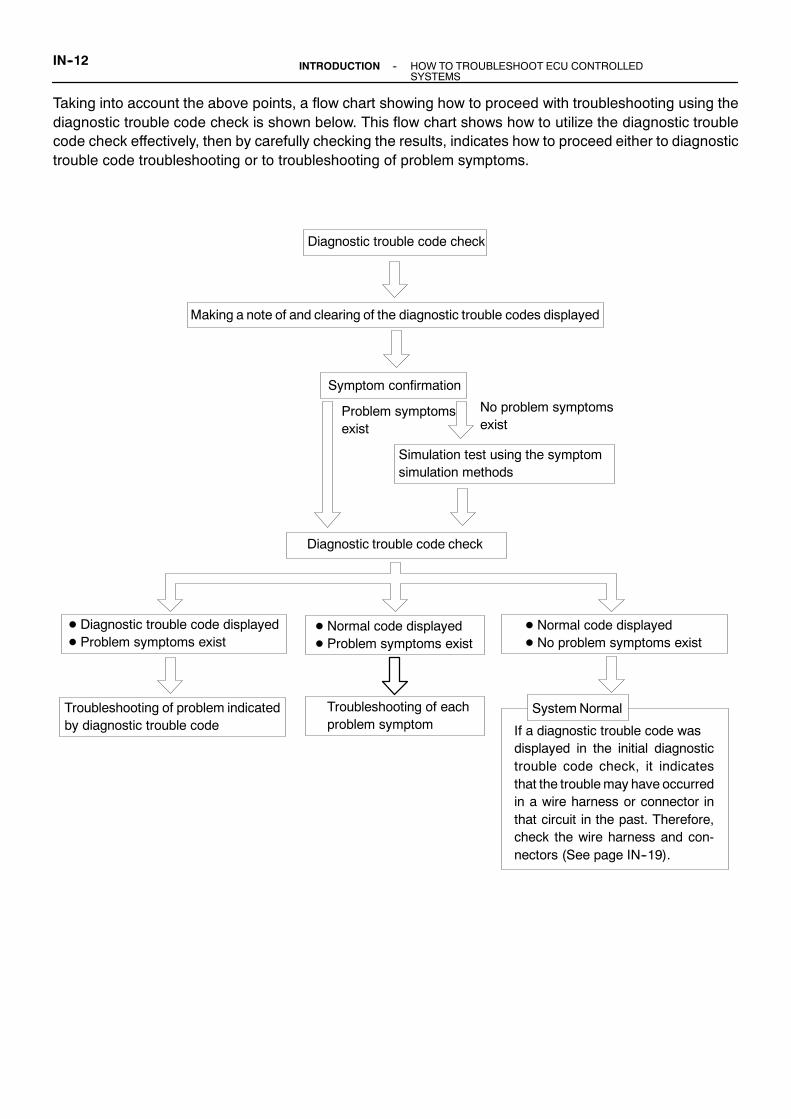
Taking into account the above points, a flow chart showing how to proceed with troubleshooting using thediagnostic trouble code check is shown below. This flow chart shows how to utilize the diagnostic troublecode check effectively, then by carefully checking the results, indicates how to proceed either to diagnostictrouble code troubleshooting or to troubleshooting of problem symptoms.
Diagnostic trouble code check
Making a note of and clearing of the diagnostic trouble codes displayed
Symptom confirmation
No problem symptomsexist
Problem symptomsexist
Simulation test using the symptomsimulation methods
D Normal code displayedD Problem symptoms exist
D Normal code displayedD No problem symptoms exist
Diagnostic trouble code check
Troubleshooting of problem indicatedby diagnostic trouble code
D Diagnostic trouble code displayedD Problem symptoms exist
SystemNormalTroubleshooting of eachproblem symptom If a diagnostic trouble code was
displayed in the initial diagnostictrouble code check, it indicatesthat the troublemay have occurredin a wire harness or connector inthat circuit in the past. Therefore,check the wire harness and con-nectors (See page IN--19).

V07268
VIBRATIONMETHOD:When vibration seems to be themajor cause.
CONNECTORS
WIRE HARNESS
PARTS AND SENSOR
1
Slightly shake the connector vertically and horizontally.
Slightly shake the wire harness vertically and horizontally.The connector joint, fulcrum of the vibration, and openingthrough portion are the major areas to be checked thorough-ly.
Apply slight vibration with a finger to the part of the sensorconsidered to be the problem cause and check if themalfunction occurs.
Shake Slightly
Swing Slightly
Vibrate Slightly
HINT: Applying strong vibration to relays may result in openrelays.
--INTRODUCTION HOW TO TROUBLESHOOT ECU CONTROLLEDSYSTEMS
IN--13
3. SYMPTOM SIMULATIONThe most difficult case in troubleshooting is when there are no problem symptoms occurring. In such cases,a thorough customer problem analysis must be carried out, then simulate the same or similar conditions andenvironment in which the problem occurred in the customer’s engine. No matter how much experience atechnician has, or how skilled he may be, if he proceeds to troubleshoot without confirming the problemsymptoms he will tend to overlook something important in the repair operation and make a wrong guesssomewhere, which will only lead to a standstill. For example, for a problem which only occurs when the en-gine is cold, or for a problem which occurs due to vibration caused by the certain rpm, etc., the problem cannever be determined so long as the symptoms are confirmed with the engine hot condition or the engineat a standstill. Since vibration, heat or water penetration (moisture) are likely causes for problems which aredifficult to reproduce, the symptom simulation tests introduced here are effective measures in that the exter-nal causes are applied to the engine in a stopped condition.Important Points in the Symptom Simulation Test:In the symptom simulation test, the problem symptoms should of course be confirmed, but the problem areaor partsmust also be found out. To do this, narrowdown the possible problemcircuits according to the symp-toms before starting this test and connect a tester beforehand. After that, carry out the symptom simulationtest, judging whether the circuit being tested is defective or normal and also confirming the problem symp-toms at the same time. Refer to the problem symptoms table for each system to narrow down the possiblecauses of the symptom.

HEAT METHOD: When the problem seems to occur when the suspect area is heated.2
NOTICE:(1) Do not heat to more than 60 ˚C (140 ˚F). (Temperatureis limited not to damage the components.)(2) Do not apply heat directly to parts in the ECU.
Heat the component that is the likely cause of the malfunctionwith a hair dryer or similar object. Check to see if themalfunctionoccurs. Ma l f u n c-
tion
IN--14 --INTRODUCTION HOW TO TROUBLESHOOT ECU CONTROLLEDSYSTEMS

D DTC No.Indicates the diagnostic trouble code.
D Page or InstructionsIndicates the pagewhere the inspection procedurefor each circuit is to be found, or gives instructionsfor checking and repairs.
D Detection ItemIndicates the system of the problem orcontents of the problem.
D Trouble AreaIndicates the suspect area of theproblem.
Mass Air Flow Circuit Malfunction
Detection Item
D Open or short in mass air flow meter circuitD Mass air flow meter
D ECM
DTC No.(See page)
Trouble Area MIL* Memory
P0100(DI--24)
P0101(DI--28)
Mass Air Flow CircuitRange/Performance Problem
D Mass air flow meter
P0115(DI--34)
D Open or short in intake air temp. sensor circuitD Intake air temp. sensor
D ECM
Intake Air Temp. Circuit MalfunctionP0110(DI--29)
Engine Coolant Temp. CircuitRange/Performance Problem
D Open or short in engine coolant temp. sensor circuitD Engine coolant temp. sensor
D ECM
P0120(DI--39)
Throttle/ Pedal Position Sensor/Switch”A” Circuit Range/Performance
P0116(DI--38)
Throttle/Pedal Position Sensor/Switch”A” Circuit Malfunction
D Engine coolant temp. sensorD Cooling system
Engine Coolant Temp. CircuitMalfunction
D Open or short in throttle position sensor circuitD Throttle position sensor
D ECM
D Throttle position sensor
DTC CHART (SAE Controlled)
HINT: Parameters listed in the chart may not be exactly the same as your reading due to the type of instrumentor other factors.
If a malfunction code is displayed during the DTC check mode, check the circuit for that code listed in the tablebelow. For details of each code, turn to the page referred to under the ”See page” for the respective ”DTCNo.”in the DTC chart.
--INTRODUCTION HOW TO TROUBLESHOOT ECU CONTROLLEDSYSTEMS
IN--15
4. DIAGNOSTIC TROUBLE CODE CHARTThe inspection procedure is shown in the table below. This table permits efficient and accurate troubleshoot-ing using the diagnostic trouble codes displayed in the diagnostic trouble code check. Proceed with trouble-shooting in accordance with the inspection procedure given in the diagnostic chart corresponding to thediagnostic trouble codesdisplayed. Theengine diagnostic trouble code chart is shown belowas anexample.

IN--16 --INTRODUCTION HOW TO TROUBLESHOOT ECU CONTROLLEDSYSTEMS
5. PROBLEM SYMPTOMS TABLEThe suspect circuits or parts for each problem symptom are shown in the table below. Use this table to trou-bleshooting the problem when a ”Normal” code is displayed in the diagnostic trouble code check but theproblem is still occurring. Numbers in the table indicate the inspection order in which the circuits or partsshould be checked.HINT:When the problem is not detected by the diagnostic system even though the problem symptom is present,it is considered that the problem is occurring outside the detection range of the diagnostic system, or thatthe problem is occurring in a system other than the diagnostic system.
Symptom Suspect Area See page
Engine does not crank (Does not start)
No initial combustion (Does not start)
No complete combustion (Does not start)
1. Starter and starter relay
1. ECM power source circuit2. Fuel pump control circuit
3. Engine control module (ECM)
1. Starter signal circuit2. Fuel pump control circuit
1. Fuel pump control circuit
PROBLEM SYMPTOMS TABLE
1. Compression2. Fuel pump control circuit
1. Fuel pump control circuit
1. Starter signal circuit2. Fuel pump control circuit
1. Starter signal circuit2. Fuel pump control circuit
3. Compression
idling)
High engine idle speed (Poor idling)
Hot engine
Cold engine (Difficult to start)
Engine cranks normally (Difficult to start)
D Problem Symptom
D PageIndicates the page where the flow chart for each circuitis located.
D Circuit Inspection, Inspection OrderIndicates the circuit which needs to be checked for each problemsymptom. Check in the order indicated by the numbers.
D Circuit or Part NameIndicates the circuit or part which needs to be checked.
ST--14 ST--15
1. ECM power source circuit
DI--147DI--151
DI--147
DI--151
DI--144
DI--151EM--3
DI--144
DI--151
DI--144
DI--151
DI--834
V08423
Knock Sensor 1
GR
ECM
KNK
E1
12E6
WIRING DIAGRAM
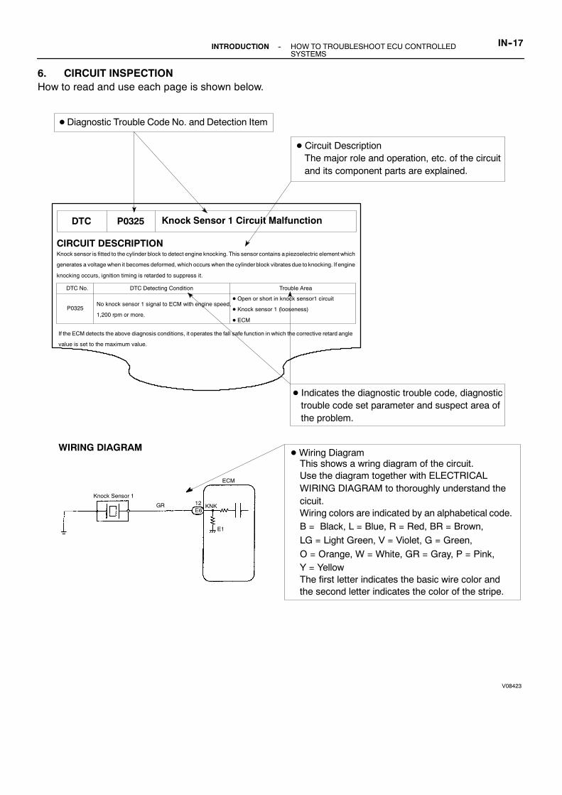
DTC P0325 Knock Sensor 1 Circuit Malfunction
CIRCUIT DESCRIPTIONKnock sensor is fitted to the cylinder block to detect engine knocking. This sensor contains a piezoelectric elementwhich
generates a voltage when it becomes deformed, which occurs when the cylinderblock vibrates due to knocking. If engine
knocking occurs, ignition timing is retarded to suppress it.
DTC No. DTC Detecting Condition Trouble Area
P0325No knock sensor 1 signal to ECM with engine speed,
1,200 rpm or more.
D Open or short in knock sensor1 circuit
D Knock sensor 1 (looseness)
D ECM
If the ECM detects the above diagnosis conditions, it operates the fall safe function in which the corrective retard angle
value is set to the maximum value.
D Diagnostic Trouble Code No. and Detection Item
D Circuit DescriptionThe major role and operation, etc. of the circuitand its component parts are explained.
D Indicates the diagnostic trouble code, diagnostictrouble code set parameter and suspect area ofthe problem.
DWiring DiagramThis shows a wring diagram of the circuit.Use the diagram together with ELECTRICALWIRING DIAGRAM to thoroughly understand thecicuit.Wiring colors are indicated by an alphabetical code.B = Black, L = Blue, R = Red, BR = Brown,
LG = Light Green, V = Violet, G = Green,
O = Orange, W = White, GR = Gray, P = Pink,Y = YellowThe first letter indicates the basic wire color andthe second letter indicates the color of the stripe.
--INTRODUCTION HOW TO TROUBLESHOOT ECU CONTROLLEDSYSTEMS
IN--17
6. CIRCUIT INSPECTIONHow to read and use each page is shown below.

V08425
LOCK
KNK
E6 Connector
(a) Remove the glove compartment (See page SF--67).(b) Disconnect the E6 connector of ECM.
INSPECTION PROCEDURE
Replace knock sensor.
1 Check continuity between terminal KNK of ECM connector and body ground.
OK:
Check knock sensor (See page SF--59).
Measure resistance between terminal KNK of ECM connectorand body ground.
Resistance: 1 MΩ or higher
Connector being checked is connected.
D Indicates the condition of the connector of ECU during the check.
PREPARATION:
CHECK:
2
Go to step 3.
OK
OK
NG
D Indicates the position of the ignition switch during the check.
Check from the connector back side.(with harness)
Ignition Switch LOCK (OFF)
Ignition Switch START
LOCKIgnition Switch ON
START
ON
D Indicates the place to check the voltage or resistance.D Indicates the connector position to checked, from the front or back side.
Connector being checked is disconnected.
Check from the connector front side. (without harness)In this case, care must be taken not to bend the terminals.
E6 Connector
KNK
Wire Harness
E6 Connector
KNK
A00255AB0117A00265
D Inspection ProcedureUse the inspection procedure to determineif the circuit is normal or abnormal, and, ifit is abnormal, use it to determine whetherthe problem is located in the sensors,actuators, wire harness or ECU.
IN--18 --INTRODUCTION HOW TO TROUBLESHOOT ECU CONTROLLEDSYSTEMS

M10046
M10047
M10048
IN02K--02
--INTRODUCTION HOW TO TROUBLESHOOT ECU CONTROLLEDSYSTEMS
IN--19
HOW TO USE THE DIAGNOSTICCHART AND INSPECTIONPROCEDURE1. CONNECTOR CONNECTION AND TERMINAL IN-
SPECTIONS For troubleshooting, diagnostic trouble code charts or
problemsymptomcharts are provided for each circuit withdetailed inspection procedures on the following pages.
S When all the component parts, wire harnesses and con-nectors of each circuit except the ECU are found to benormal in troubleshooting, then it is determined that theproblem is in the ECU. Accordingly, if diagnosis is per-formed without the problem symptoms occurring,refer tostep 8 to replace the ECU, even if the problem is not in theECU. So always confirm that the problem symptoms areoccurring, or proceed with inspection while using thesymptom simulation method.
S The instructions ”Checkwire harness and connector” and”Check and replace ECU” which appear in the inspectionprocedure, are common and applicable to all diagnostictrouble codes. Follow the procedure outlined belowwhenever these instructions appear.
OPEN CIRCUIT:This could be due to and a disconnected wire harness, faultycontact in the connector, a connector terminal pulled out, etc.HINT:S It is rarely the case that a wire is broken in the middle of
it. Most cases occur at the connector. In particular, care-fully check the connectors of sensors and actuators.
S Faulty contact could be due to rusting of the connectorterminals, to foreign materials entering terminals or a de-formation of connector terminals between the male andfemale terminals of the connector. Simply disconnectingand reconnecting the connectors once changes thecondition of the connection and may result in a return tonormal operation. Therefore, in troubleshooting, if no ab-normality is found in the wire harness and connectorcheck, but the problem disappears after the check, thenthe cause is considered to be in the wire harness or con-nectors.
SHORT CIRCUIT:This could be due to a connect between the wire harness andthe body ground or to a short occurred inside the switch etc.HINT:When there is a short between the wire harness and bodyground, check thoroughly whether the wire harness is caughtin the body or is clamped properly.

IN0379
Sensor SideECU Side
IN0378
Sensor Side
ECU Side
IN0380
Sensor Side
ECU Side
IN0381
Pull LightlyLooseness of Crimping
IN--20 --INTRODUCTION HOW TO TROUBLESHOOT ECU CONTROLLEDSYSTEMS
2. CONTINUITY CHECK (OPEN CIRCUIT CHECK)(a) Disconnect the connectors at both ECU and sensor
sides.(b) Measure the resistance between the applicable terminals
of the connectors.HINT:S Measure the resistance while lightly shaking the wire har-
ness vertically and horizontally.S When tester probes are inserted into a connector, insert
the probes from the back. For waterproof connectors inwhich the probes cannot be inserted from the back, becareful not to bend the terminals when inserting the testerprobes.
3. RESISTANCE CHECK (SHORT CIRCUIT CHECK)(a) Disconnect the connectors on both ends.(b) Measure the resistance between the applicable terminals
of the connectors and body ground. Be sure to carry outthis check on the connectors on both ends.Resistance: 1 MΩ or higher
HINT:Measure the resistance while lightly shaking the wire harnessvertically and horizontally.
4. VISUAL CHECK AND CONTACT PRESSURE CHECK(a) Disconnect the connectors at both ends.(b) Check for rust or foreign material, etc. in the terminals of
the connectors.(c) Check crimped portions for looseness or damage and
check if the terminals are secured in lock portion.HINT:The terminals should not come out when pulled lightly.(d) Prepare a testmale terminal and insert it in the female ter-
minal, then pull it out.NOTICE:When testing a gold--plated female terminal, always use agold--plated male terminal.HINT:When the test terminal is pulled out more easily than others,there may be poor contact in that section.
FI7187
Z17004
C B AOPENSensor
Fig. 1 ECU
1
2
1
2
1
2 2
1
Z17005
Fig. 2
Sensor
ECU
C BA
12
12
12
Z17807
Fig. 3
Sensor
ECUC A12
12
12 2
1B2 B1
--INTRODUCTION HOW TO TROUBLESHOOT ECU CONTROLLEDSYSTEMS
IN--21
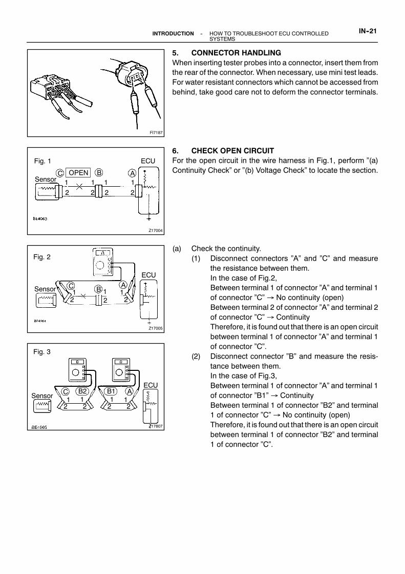
5. CONNECTOR HANDLINGWhen inserting tester probes into a connector, insert them fromthe rear of the connector. When necessary, use mini test leads.For water resistant connectors which cannot be accessed frombehind, take good care not to deform the connector terminals.
6. CHECK OPEN CIRCUITFor the open circuit in the wire harness in Fig.1, perform ”(a)Continuity Check” or ”(b) Voltage Check” to locate the section.
(a) Check the continuity.(1) Disconnect connectors ”A” and ”C” and measure
the resistance between them.In the case of Fig.2,Between terminal 1 of connector ”A” and terminal 1of connector ”C”→ No continuity (open)Between terminal 2 of connector ”A” and terminal 2of connector ”C”→ ContinuityTherefore, it is found out that there is an open circuitbetween terminal 1 of connector ”A” and terminal 1of connector ”C”.
(2) Disconnect connector ”B” and measure the resis-tance between them.In the case of Fig.3,Between terminal 1 of connector ”A” and terminal 1of connector ”B1”→ ContinuityBetween terminal 1 of connector ”B2” and terminal1 of connector ”C”→ No continuity (open)Therefore, it is found out that there is an open circuitbetween terminal 1 of connector ”B2” and terminal1 of connector ”C”.

Z17007
Fig. 4
Sensor CA
12
12
12
ECU
B
5 V
5 V0 V
5 V
Z17008
C B ASHORT
Fig. 5
12
12 2
1
Z17009
Fig. 6
Sensor
ECUC B A12
12
12
IN--22 --INTRODUCTION HOW TO TROUBLESHOOT ECU CONTROLLEDSYSTEMS
(b) Check the voltage.In a circuit in which voltage is applied (to the ECUconnec-tor terminal), an open circuit can be checked for by con-ducting a voltage check.As shown in Fig.4, with each connector still connected,measure the voltage between body ground and terminal1 of connector ”A” at the ECU 5V output terminal, terminal1 of connector ”B”, and terminal 1 of connector ”C”, in thatorder.
If the results are:5V: Between Terminal 1 of connector ”A” and Body Ground5V: Between Terminal 1 of connector ”B” and Body Ground0V: Between Terminal 1 of connector ”C” and Body GroundThen it is found out that there is an open circuit in the wire har-ness between terminal 1 of ”B” and terminal 1 of ”C”.
7. CHECK SHORT CIRCUITIf the wire harness is ground shorted as in Fig.5, locate the sec-tion by conducting a ”continuity check with ground”.
Check the continuity with ground.(1) Disconnect connectors ”A” and ”C” and measure
the resistance between terminal 1 and 2 of connec-tor ”A” and body ground.In the case of Fig.6Between terminal 1 of connector ”A” and bodyground → Continuity (short)Between terminal 2 of connector ”A” and bodyground → No continuityTherefore, it is found out that there is a short circuitbetween terminal 1 of connector ”A” and terminal 1of connector ”C”.

Z17808
Fig. 7
Sensor
ECUC A12
12
12 2
1B2 B1
IN0383
Example
Ground
IN0384
ECU Side
Ground
W/H Side
Ground
--INTRODUCTION HOW TO TROUBLESHOOT ECU CONTROLLEDSYSTEMS
IN--23
(2) Disconnect connector ”B” and measure the resis-tance between terminal 1 of connector ”A” and bodyground, and terminal 1 of connector ”B2” and bodyground.Between terminal 1 of connector ”A” and bodyground → No continuityBetween terminal 1 of connector ”B2” and bodyground → Continuity (short)Therefore, it is found out that there is a short circuitbetween terminal 1 of connector ”B2” and terminal1 of connector ”C”.
8. CHECK AND REPLACE ECUFirst check the ECU ground circuit. If it is faulty, repair it. If it isnormal, the ECU could be faulty, so replace the ECUwith a nor-mal functioning one and check that the symptoms appear.
(1) Measure the resistance between the ECU groundterminal and the body ground.
Resistance: 1 Ω or less
(2) Disconnect the ECU connector, check the groundterminals on the ECU side and the wire harnessside for bend and check the contact pressure.

IN03P--02
IN--24--INTRODUCTION TERMS
TERMSABBREVIATIONS USED IN THIS MANUAL
Abbreviations Meaning
ATF Automatic Transmission Fluid
BTDC Before Top Dead Center
CB Circuit Breaker
DOHC Double Over Head Cam
DP Dash Pot
ECU Electronic Control Unit
ELR Emergency Locking Retractor
ESA Electronic Spark Advance
EX Exhaust (Manifold, Valve)
FIPG Formed in Place Gasket
FL Fusible Link
FPU Fuel Pressure Up
Fr Front
HAC High Altitude Compensation
IG Ignition
IIA Integrated Ignition Assembly
IN Intake (Manifold, Valve)
J/B Junction Block
LED Light Emitting Diode
LH Left--Hand
LSPV Load Sensing Proportioning valve
Max. Maximum
Min. Minimum
MP Multipurpose
O/S Oversize
P&BV Proportioning and Bypass Valve
PCV Positive Crankcase Ventilation
RH Right--Hand
Rr Rear
SSM Special Service Materials
SST Special Service Tools
STD Standard
SW Switch
TDC Top Dead center
TEMP. Temperature
T/M Transmission
U/S Undersize
VCV Vacuum Control Valve
VSV Vacuum Switching Valve
VTV Vacuum Transmitting Valve
w/ With
w/o Without
IN03Q--01
--INTRODUCTION TERMSIN--25
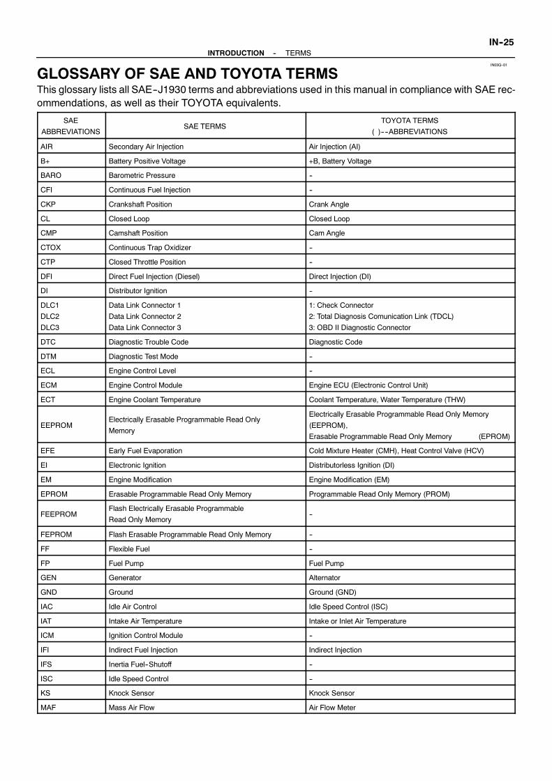
GLOSSARY OF SAE AND TOYOTA TERMSThis glossary lists all SAE--J1930 terms and abbreviations used in this manual in compliance with SAE rec-ommendations, as well as their TOYOTA equivalents.
SAE
ABBREVIATIONSSAE TERMS
TOYOTA TERMS
( )----ABBREVIATIONS
AIR Secondary Air Injection Air Injection (AI)
B+ Battery Positive Voltage +B, Battery Voltage
BARO Barometric Pressure --
CFI Continuous Fuel Injection --
CKP Crankshaft Position Crank Angle
CL Closed Loop Closed Loop
CMP Camshaft Position Cam Angle
CTOX Continuous Trap Oxidizer --
CTP Closed Throttle Position --
DFI Direct Fuel Injection (Diesel) Direct Injection (DI)
DI Distributor Ignition --
DLC1
DLC2
DLC3
Data Link Connector 1
Data Link Connector 2
Data Link Connector 3
1: Check Connector
2: Total Diagnosis Comunication Link (TDCL)
3: OBD II Diagnostic Connector
DTC Diagnostic Trouble Code Diagnostic Code
DTM Diagnostic Test Mode --
ECL Engine Control Level --
ECM Engine Control Module Engine ECU (Electronic Control Unit)
ECT Engine Coolant Temperature Coolant Temperature, Water Temperature (THW)
EEPROMElectrically Erasable Programmable Read Only
Memory
Electrically Erasable Programmable Read Only Memory
(EEPROM),
Erasable Programmable Read Only Memory (EPROM)
EFE Early Fuel Evaporation Cold Mixture Heater (CMH), Heat Control Valve (HCV)
EI Electronic Ignition Distributorless Ignition (DI)
EM Engine Modification Engine Modification (EM)
EPROM Erasable Programmable Read Only Memory Programmable Read Only Memory (PROM)
FEEPROMFlash Electrically Erasable Programmable
Read Only Memory--
FEPROM Flash Erasable Programmable Read Only Memory --
FF Flexible Fuel --
FP Fuel Pump Fuel Pump
GEN Generator Alternator
GND Ground Ground (GND)
IAC Idle Air Control Idle Speed Control (ISC)
IAT Intake Air Temperature Intake or Inlet Air Temperature
ICM Ignition Control Module --
IFI Indirect Fuel Injection Indirect Injection
IFS Inertia Fuel--Shutoff --
ISC Idle Speed Control --
KS Knock Sensor Knock Sensor
MAF Mass Air Flow Air Flow Meter

IN--26--INTRODUCTION TERMS
MAP Manifold Absolute PressureManifold Pressure
Intake Vacuum
MC Mixture Control
Electric Bleed Air Control Valve (EBCV)
Mixture Control Valve (MCV)
Electric Air Control Valve (EACV)
MDP Manifold Differential Pressure --
MFI Multiport Fuel Injection Electronic Fuel Injection (EFI)
MIL Malfunction Indicator Lamp Check Engine Light
MST Manifold Surface Temperature --
MVZ Manifold Vacuum Zone --
NVRAM Non--Volatile Random Access Memory --
OBD On--Board Diagnostic On--Board Diagnostic (OBD)
OP Open Loop Open Loop
PAIR Pulsed Secondary Air Injection Air Suction (AS)
PCM Powertrain Control Module --
PROM Programmable Read Only Memory --
RAM Random Access Memory Random Access Memory (RAM)
RM Relay Module --
ROM Read Only Memory Read Only Memory (ROM)
RPM Engine Speed Engine Speed
SFI Sequential Multiport Fuel Injection Electronic Fuel Injection (EFI), Sequential Injection
SRI Service Reminder Indicator --
SRT System Readiness Test --
ST Scan Tool --
TB Throttle Body Throttle Body
TBI Throttle Body Fuel InjectionSingle Point Injection
Central Fuel Injection (Ci)
TCM Transmission Control Module Transmission ECU (Electronic Control Unit)
TP Throttle Position Throttle Position
TR Transmission Range --
TVV Thermal Vacuum ValveBimetallic Vacuum Switching Valve (BVSV)
Thermostatic Vacuum Switching Valve (TVSV)
VAF Volume Air Flow Air Flow Meter
VR Voltage Regulator Voltage Regulator
WOT Wide Open Throttle Full Throttle

INTRODUCTION
HOW TO USE THIS MANUAL IN--1. . . . . . . . . . . . .GENERAL INFORMATION IN--1. . . . . . . . . . . . . . . . . .
IDENTIFICATION INFORMATION IN--3. . . . . . . . . .ENGINE SERIAL NUMBER IN--3. . . . . . . . . . . . . . . . .
REPAIR INSTRUCTIONS IN--4. . . . . . . . . . . . . . . . .GENERAL INFORMATION IN--4. . . . . . . . . . . . . . . . . .
ENGINE SLING AND SUPPORT POSITIONS IN--7. .
HOW TO TROUBLESHOOT
ECU CONTROLLED SYSTEMS IN--8. . . . . . . . .GENERAL INFORMATION IN--8. . . . . . . . . . . . . . . . . .
HOW TO PROCEED
WITH TROUBLESHOOTING IN--9. . . . . . . . . . . . . .
HOW TO USE THE DIAGNOSTIC CHART AND
INSPECTION PROCEDURE IN--19. . . . . . . . . . . . . . .
TERMS IN--24. . . . . . . . . . . . . . . . . . . . . . . . . . . . . . . . .ABBREVIATIONS USED IN THIS MANUAL IN--24. . . .
GLOSSARY OF SAE AND TOYOTA TERMS IN--25. .

PP0YR--01
--PREPARATION ENGINE MECHANICALPP--1
ENGINE MECHANICALSST (Special Service Tools)
09201--01055 Valve Guide Bushing Remover & Re
placer 5.5
09201--41020 Valve Stem Oil Seal Replacer
09202--70020 Valve Spring Compressor
(09202--00010) Attachment
09213--70010 Crankshaft Pulley Holding Tool
(90105--08076) Bolt
09222--30010 Connecting Rod Bushing Remover
& Replacer
09223--46011 Crankshaft Front Oil Seal
Replacer
Camshaft oil seal
Crankshaft pulley
Crankshaft timing pulley
09223--56010 Crankshaft Rear Oil Seal
Replacer
(09316--00011) Replacer Pipe Crankshaft front oil seal
09330--00021 Companion Flange Holding Tool Crankshaft pulley
09843--18040 Diagnosis Check Wire No.2

PP--2--PREPARATION ENGINE MECHANICAL
09950--50010 Puller C Set
(09951--05010) Hanger 150 Crankshaft pulley
Crankshaft timing pulley
(09952--05010) Slide Arm Crankshaft pulley
Crankshaft timing pulley
(09953--05010) Center Bolt 100 Crankshaft pulley
Crankshaft timing pulley
(09953--05020) Center Bolt 150 Crankshaft pulley
Crankshaft timing pulley
(09954--05010) Claw No.1 Crankshaft timing pulley
(09954--05020) Claw No.2 Crankshaft pulley
09950--60010 Replacer Set
(09951--00240) Replacer 24 Spark plug tube
(09951--00440) Replacer 44 Spark plug tube
(09952--06010) Adapter Spark plug tube
09950--70010 Handle Set
(09951--07100) Handle 100 Spark plug tube
Valve guide bushing
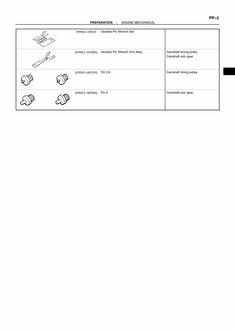
--PREPARATION ENGINE MECHANICALPP--3
09960--10010 Variable Pin Wrench Set
(09962--01000) Variable Pin Wrench Arm Assy Camshaft timing pulley
Camshaft sub--gear
(09963--00350) Pin 3.5 Camshaft timing pulley
(09963--00500) Pin 5 Camshaft sub--gear

PP0YS--01
PP--4--PREPARATION ENGINE MECHANICAL
RECOMMENDED TOOLS09040--00010 Hexagon Wrench Set .
09090--04010 Engine Sling Device . For suspension engine
09200--00010 Engine Adjust Kit .
09258--00030 Hose Plug Set . Plug for vacuum hose, fuel
hose etc.
09904--00010 Expander Set .

PP0YT--01
--PREPARATION ENGINE MECHANICALPP--5
EQUIPMENTCaliper gauge
Compression gauge
Connecting rod aligner
Cylinder gauge
Dial indicator
Dye penetrant
Engine tune--up tester
Heater
Magnetic finger
Micrometer
OBD II scan tool
Piston ring compressor
Piston ring expander
Plastigage
Precision straight edge
Soft brush
Spring tester Valve spring
Steel square Valve spring
Thermometer
Torque wrench
Valve seat cutter
Vernier calipers

PP0YU--01
PP--6--PREPARATION ENGINE MECHANICAL
SSM (Service Special Materials)08826--00080 Seal Packing Black or equivalent
(FIPG)
Camshaft bearing cap
Cylinder head semi--circular plug
Cylinder head cover
Rear oil sear retainer
08826--00100 Seal Packing 1282B,
THREE BOND 1282B or equivalent
(FIPG)
Coolant drain union
08833--00070 Adhesive 1324,
THREE BOND 1324 or equivalent
Drive plate bolt
Spark plug tube
08833--00080 Adhesive 1344
THREE BOND 1344
LOCTITE 242 or equivalent
No.1 idler pulley bolt

PP0YV--01
--PREPARATION SFIPP--7
SFISST (Special Service Tools)
09268--41047 Injection Measuring Tool Set
09268--45014 EFI Fuel Pressure Gauge
(09268--41190) Adaptor
(90405--06167) I Union
09612--24014 Steering Gear Housing Overhaul
Tool Set
(09617--24011) Steering Rack Wrench Fuel pressure pulsation damper
09816--30010 Oil Pressure Switch Socket Knock sensor
09842--30070 Wiring ”F” EFI Inspection
09843--18020 Diagnosis Check Wire

PP0YW--01
PP--8--PREPARATION SFI
RECOMMENDED TOOLS09082--00040 TOYOTA Electrical Tester.
09200--00010 Engine Adjust Kit .
09258--00030 Hose Plug Set . Plug for vacuum hose, fuel
hose etc.

PP0Y9--01
--PREPARATION COOLINGPP--9
COOLINGEQUIPMENTGasket scraper
Heater Thermostat
Thermometer Thermostat
Torque wrench

PP0YB--01
PP--10--PREPARATION COOLING
SSM (Service Special Materials)08826--00100 Seal Packing 1282B,
THREE BOND 1282B or equivalent
(FIPG)
Water pump
Water inlet housing

PP0Y2--01
--PREPARATION LUBRICATIONPP--11
LUBRICATIONSST (Special Service Tools)
09032--00100 Oil Pan Seal Cutter
09228--07501 Oil Filter Wrench

PP0Y3--01
PP--12--PREPARATION LUBRICATION
RECOMMENDED TOOLS09200--00010 Engine Adjust Kit .
09040--00010 Hexagon Wrench Set .

PP0Y4--01
--PREPARATION LUBRICATIONPP--13
EQUIPMENTOil pressure gauge
Precision straight edge
Torque wrench

PP0Y6--01
PP--14--PREPARATION LUBRICATION
LUBRICANTItem Capacity Classification
Engine oil
Dry fill
Drain and refill
w/ Oil filter change
w/o Oil filter change
7.0 liters (7.4 US qts, 6.2 lmp. qts)
5.3 liters (5.6 US qts, 4.9 lmp. qts)
5.0 liters (5.3 US qts, 4.4 lmp. qts)
API grade SH, Energy--Conserving II or SJ,
Energy--Conserving or ILSAC multigrade engine
oil. SAE 5W--30 is the best choice for your ve-
hicle, for good fuel economy, and good starting in
cold weather.
PP0Y5--01
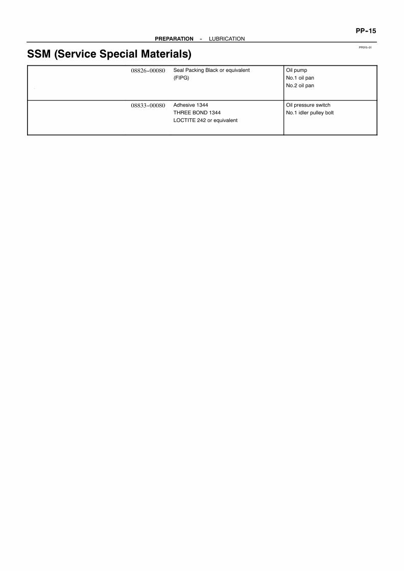
--PREPARATION LUBRICATIONPP--15
SSM (Service Special Materials)08826--00080 Seal Packing Black or equivalent
(FIPG)
Oil pump
No.1 oil pan
No.2 oil pan
08833--00080 Adhesive 1344
THREE BOND 1344
LOCTITE 242 or equivalent
Oil pressure switch
No.1 idler pulley bolt

PP0YK--01
PP--16--PREPARATION IGNITION
IGNITIONRECOMMENDED TOOLS
09082--00050 TOYOTA Electrical Tester Set.
09200--00010 Engine Adjust Kit .

PP0YL--01
--PREPARATION IGNITIONPP--17
EQUIPMENTMegger (Insulation resistance meter) Spark plug
Spark plug cleaner
Torque wrench
Ohmmeter

PP0YH--01
PP--18--PREPARATION STARTING
STARTINGSST (Special Service Tools)
09286--46011 Injection Pump Spline Shaft
Puller
Armature front bearing
09810--38140 Starter Magnet Switch Nut Wrench
14
09820--00030 Alternator Rear Bearing Replacer Armature bearing

PP0YI--01
--PREPARATION STARTINGPP--19
RECOMMENDED TOOLS09082--00040 TOYOTA Electrical Tester.

PP0YJ--01
PP--20--PREPARATION STARTING
EQUIPMENTDial indicator Commutator
Magnetic finger Steel ball
Pull scale Brush spring
Sandpaper Commutator
Torque wrench
V--block Commutator
Vernier calipers Commutator, Brush

PP0YE--01
--PREPARATION CHARGINGPP--21
CHARGINGSST (Special Service Tools)
09285--76010 Injection Pump Camshaft Bearing
Cone Replacer
Rotor rear bearing cover
09286--46011 Injection Pump Spline Shaft
Puller
Rectifier end frame
09820--00021 Alternator Rear Bearing Puller
09820--00030 Alternator Rear Bearing Replacer
09820--63010 Alternator Pulley Set Nut Wrench
Set
09950--60010 Replacer Set Rotor front bearing
(09951--00260) Replacer 26
(09951--00500) Replacer 50
(09952--06010) Adapter

PP0YF--01
PP--22--PREPARATION CHARGING
RECOMMENDED TOOLS09082--00040 TOYOTA Electrical Tester.

PP0YG--01
--PREPARATION CHARGINGPP--23
EQUIPMENTAmmeter(A)
Torque wrench
Vernier calipers Rotor (Slip ring)

PREPARATION
ENGINE MECHANICAL PP--1. . . . . . . . . . . . . . . . . . .
SFI PP--7. . . . . . . . . . . . . . . . . . . . . . . . . . . . . . . . . . . . .
COOLING PP--9. . . . . . . . . . . . . . . . . . . . . . . . . . . . . . .
LUBRICATION PP--11. . . . . . . . . . . . . . . . . . . . . . . . . . .
IGNITION PP--16. . . . . . . . . . . . . . . . . . . . . . . . . . . . . . .
STARTING PP--18. . . . . . . . . . . . . . . . . . . . . . . . . . . . . .
CHARGING PP--21. . . . . . . . . . . . . . . . . . . . . . . . . . . . .

SS00F--01
V06821
Mark MarkClass Class
Hexagon headbolt
BoltheadNo.
4--
5--
6--
7--
8--
9--10--
11--
4T
5T
6T
7T
8T
9T
10T
11T
No mark
No mark
Hexagonflange bolt
w/ washerhexagon bolt
4T
4T
5T
6T
7T
8T
Hexagon headbolt
Hexagonflange bolt
w/ washerhexagon bolt
Hexagon headbolt
Hexagon headbolt
2Protrudinglines
2Protrudinglines
3Protrudinglines
4Protrudinglines
Hexagonflange bolt
w/ washerhexagon bolt
Hexagonflange bolt
w/ washerhexagon bolt
Hexagonflange bolt
w/ washerhexagon bolt
Stud bolt
Welded bolt
4Protrudinglines
5Protrudinglines
6Protrudinglines
No mark
Grooved
9T
10T
11T
4T
6T
4T
--SERVICE SPECIFICATIONS STANDARD BOLTSS--1
STANDARD BOLTHOW TO DETERMINE BOLT STRENGTH

SS00G--01
V00079
ClassDiametermm
Pitchmm
Specified torqueHexagon head bolt Hexagon flange bolt
N·m kgf·cm ft·lbf N·m kgf·cm ft·lbf
in.·lbf
in.·lbf
in.·lbf
in.·lbf
in.·lbf
in.·lbf
SS--2--SERVICE SPECIFICATIONS STANDARD BOLT
SPECIFIED TORQUE FOR STANDARD BOLTS

SS0HU--01
--SERVICE SPECIFICATIONS ENGINE MECHANICALSS--3
ENGINE MECHANICALSERVICE DATACompression
pressure
at 250 rpm STD
Minimum
Difference of pressure between each cylinder
1,226 kPa (12.5 kgf/cm2, 178 psi) or more
981 kPa (10.0 kgf/cm2, 142 psi)
98 kPa (1.0 kgf/cm2, 14 psi) or less
Valve
clearance
at cold Intake
Exhaust
Valve clearance adjusting shim No.00
No.02
No.04
No.06
No.08
No.10
No.12
No.14
No.16
No.18
No.20
No.22
No.24
No.26
No.28
No.30
No.32
No.34
No.36
No.38
No.40
No.42
No.44
No.46
No.48
No.50
No.52
No.54
No.56
No.58
No.60
No.62
No.64
No.66
No.68
No.70
No.72
No.74
No.76
No.78
No.80
0.15 -- 0.25 mm (0.006 -- 0.010 in.)
0.25 -- 0.35 mm (0.010 -- 0.014 in.)
2.000 mm (0.0787 in.)
2.020 mm (0.0795 in.)
2.040 mm (0.0803 in.)
2.060 mm (0.0811 in.)
2.080 mm (0.0819 in.)
2.100 mm (0.0827 in.)
2.120 mm (0.0835 in.)
2.140 mm (0.0843 in.)
2.160 mm (0.0850 in.)
2.180 mm (0.0858 in.)
2.200 mm (0.0866 in.)
2.220 mm (0.0874 in.)
2.240 mm (0.0882 in.)
2.260 mm (0.0890 in.)
2.280 mm (0.0898 in.)
2.300 mm (0.0906 in.)
2.320 mm (0.0913 in.)
2.340 mm (0.0921 in.)
2.360 mm (0.0929 in.)
2.380 mm (0.0937 in.)
2.400 mm (0.0945 in.)
2.420 mm (0.0953 in.)
2.440 mm (0.0961 in.)
2.460 mm (0.0969 in.)
2.480 mm (0.0976 in.)
2.500 mm (0.0984 in.)
2.520 mm (0.0992 in.)
2.540 mm (0.1000 in)
2.560 mm (0.1008 in.)
2.580 mm (0.1016 in.)
2.600 mm (0.1024 in.)
2.620 mm (0.1031 in.)
2.640 mm (0.1039 in.)
2.660 mm (0.1047 in.)
2.680 mm (0.1055 in.)
2.700 mm (0.1063 in.)
2.720 mm (0.1071 in.)
2.740 mm (0.1079 in.)
2.760 mm (0.1087 in.)
2.780 mm (0.1094 in.)
2.800 mm (0.1102 in.)
Ignition timing w/ Terminals TC and E1 connected of DLC1 8 --12˚ BTDC @ idle
Idle speed -- 700 ± 50 rpm
Timing belt
tensioner
Protrusion from housing end 10.5 -- 11.5 mm (0.413 -- 0.453 in.)

SS--4--SERVICE SPECIFICATIONS ENGINE MECHANICAL
Cylinder head Warpage Maximum
Valve seat
Refacing angle
Contacting angle
Contacting width
Valve guide bushing bore diameter STD
O/S 0.05
Cylinder head bolt thread inside diameter STD
Minimum
0.10 mm (0.039 in.)
30˚, 45˚, 60˚45˚1.0 -- 1.4 mm (0.039 -- 0.055 in.)
10.285 -- 10.306 mm (0.4049 -- 0.4057 in.)
10.335 -- 10.356 mm (0.4069 -- 0.4077 in.)
9.770 -- 9.960 mm (0.3846 -- 0.3921 in.)
9.60 mm (0.3780 in.)
Valve guide
bushing
Inside diameter
Outside diameter (for repair part) STD
O/S 0.05
5.510 -- 5.530 mm (0.2169 -- 0.2177 in.)
10.333 -- 10.344 mm (0.4068 -- 0.4072 in.)
10.383 -- 10.394 mm (0.4088 -- 0.4092 in.)
Valve Valve overall length STD Intake
Exhaust
Minimum Intake
Exhaust
Valve face angle
Stem diameter Intake
Exhaust
Stem oil clearance STD Intake
Exhaust
Maximum Intake
Exhaust
Margin thickness STD
Minimum
94.80 -- 95.30 mm (3.7323 -- 3.7520 in.)
94.85 -- 95.35 mm (3.7342 -- 3.7539 in.)
94.55 mm (3.7224 in.)
94.60 mm (3.7244 in.)
44.5˚5.470 -- 5.485 mm (0.2154 -- 0.2159 in.)
5.465 -- 5.480 mm (0.2152 -- 0.2157 in.)
0.025 -- 0.060 mm (0.0010 -- 0.0024 in.)
0.030 -- 0.065 mm (0.0012 -- 0.0026 in.)
0.08 mm (0.0031 in.)
0.10 mm (0.0039 in.)
1.0 mm (0.039 in.)
0.5 mm (0.020 in.)
Valve spring Deviation Maximum
Free length
Installed tension at 35.0 mm (1.378 in.)
2.0 mm (0.079 in.)
54.05 -- 54.15 mm (2.1279 -- 2.1319 in.)
204 -- 226 N (20.8 -- 23.0 kgf·cm, 45.9 -- 50.7 lbf)
Valve lifter Lifter diameter
Lifter bore diameter
Oil clearance STD
Maximum
30.966 -- 30.976 mm (1.2191 -- 2.2195 in.)
31.000 -- 31.016 mm (1.2205 -- 1.2211 in.)
0.024 -- 0.050 mm (0.0009 -- 0.0020 in.)
0.07 mm (0.0028 in.)
Camshaft Thrust clearance STD Intake
Exhaust
Maximum Intake
Exhaust
Journal oil clearance STD
Maximum
Journal diameter Intake (A)
Others
Circle runout
Cam lobe height STD Intake
Exhaust
Minimum Intake
Exhaust
Camshaft gear backlash STD
Maximum
Camshaft gear spring end free distance
0.060 -- 0.100 mm (0.0024 -- 0.0039 in.)
0.040 -- 0.090 mm (0.0016 -- 0.0035 in.)
0.13 mm (0.0051 in.)
0.12 mm (0.0047 in.)
0.030 -- 0.067 mm (0.0012 -- 0.0026 in.)
0.10 mm (0.0039 in.)
30.984 -- 31.000 mm (1.2198 -- 1.2205 in.)
26.954 -- 26.970 mm (1.0612 -- 1.0618 in.)
0.08 mm (0.0031 in.)
42.610 -- 42.710 mm (1.6776 -- 1.6815 in.)
42.630 -- 42.730 mm (1.6783 -- 1.6823 in.)
42.46 mm (1.6717 in.)
42.48 mm (1.6724 in.)
0.020 -- 0.200 mm (0.0008 -- 0.0079 in.)
0.30 mm (0.0188 in.)
18.2 -- 18.8 mm (0.712 -- 0.740 in.)
Camshaft timing
tube
Journal diameter Green peinted mark
Red peinted mark
Journal oil clearance Sylinder head mark A
Sylinder head mark B
Maximum
39.958 -- 39.964 mm (1.5731 -- 1.5734 in.)
39.964 -- 39.970 mm (1.5734 -- 1.5736 in.)
0.036 -- 0.050 mm (0.0014 -- 0.0020 in.)
0.038 -- 0.052 mm (0.0015 -- 0.0021 in)
0.085 mm (0.0033 in.)
Manifold Warpage Maximum Intake
Exhaust
0.15 mm (0.0059 in.)
0.50 mm (0.0197 in.)

--SERVICE SPECIFICATIONS ENGINE MECHANICALSS--5
Cylinder block Cylinder head surface warpage Maximum
Cylinder bore diameter STD Mark 1
Mark 2
Mark 3
Maximum
Main bearing cap bolt tension portion diameter
STD
Minimum
0.07 mm (0.0028 in.)
87.500 -- 87.510 mm (3.4449 -- 3.4453 in.)
87.510 -- 87.520 mm (3.4453 -- 3.4457 in.)
87.520 -- 87.530 mm (3.4457 -- 3.4461 in.)
87.73 mm (3.4539 in.)
7.500 -- 7.600 mm (0.2953 -- 0.2992 in.)
7.20 mm (0.2835 in.)
Piston and
piston ring
Piston diameter STD Mark 1
Mark 2
Mark 3
Piston oil clearance STD
Maximum
Piston ring groove clearance No.1
No.2
Piston ring end gap STD No.1
No.2
Oil
Maximum No.1
No.2
Oil
87.406 -- 87.416 mm (3.4411 -- 3.4416 in.)
87.416 -- 87.426 mm (3.4416 -- 3.4420 in.)
87.426 -- 87.436 mm (3.4420 -- 3.4424 in.)
0.084 -- 0.104 mm (0.0033 -- 0.0041 in.)
0.124 mm (0.0049 in.)
0.020 -- 0.070 mm (0.0008 -- 0.0028 in.)
0.010 -- 0.050 mm (0.0004 -- 0.0020 in.)
0.250 -- 0.450 mm (0.0098 -- 0.0177 in.)
0.500 -- 0.700 mm (0.0197 -- 0.0276 in.)
0.150 -- 0.500 mm (0.0059 -- 0.0197 in.)
1.05 mm (0.0413 in.)
1.30 mm (0.0512 in.)
1.10 mm (0.0433 in.)
Connecting rod Thrust clearance STD
Maximum
Connecting rod thickness
Connecting rod oil clearance STD
Maximum
Connecting rod bearing center wall thickness
(Reference) Mark 2
Mark 3
Mark 4
Mark 5
Mark 6
Mark 7
Rod bend Maximum per 100 mm (3.94 in.)
Rod twist Maximum per 100 mm (3.94 in.)
Bushing inside diameter
Piston pin diameter
Bushing oil clearance STD
Maximum
Connecting rod bolt tension portion diameter STD
Minimum
0.160 -- 0.290 mm (0.0063 -- 0.0138 in.)
0.35 mm (0.0138 in.)
22.880 -- 22.920 mm (0.9008 -- 0.9024 in.)
0.027 -- 0.053 mm (0.0011 -- 0.0021 in.)
0.065 mm (0.0026 in.)
1.484 -- 1.487 mm (0.0584 -- 0.0585 in.)
1.487 -- 1.490 mm (0.0585 -- 0.0587 in.)
1.490 -- 1.493 mm (0.0587 -- 0.0588 in.)
1.493 -- 1.496 mm (0.0588 -- 0.0589 in.)
1.496 -- 1.499 mm (0.0589 -- 0.0590 in.)
1.499 -- 1.502 mm (0.0590 -- 0.0591 in.)
0.05 mm (0.0020 in.)
0.15 mm (0.0059 in.)
22.005 -- 22.014 mm (0.8663 -- 0.8667 in.)
21.997 -- 22.006 mm (0.8660 -- 0.8664 in.)
0.005 -- 0.011 mm (0.0002 -- 0.0004 in)
0.05 mm (0.0020 in.)
7.200 -- 7.300 mm (0.2835 -- 0.2874 in.)
7.00 mm (0.2756 in.)
Crankshaft Thrust clearance STD
Maximum
Thrust washer thickness
Main journal bore diameter on cylinder block
(with main bearing)
Main journal oil clearance STD No.1 and No.5
Others
Maximum No.1 and No.5
Others
Main journal diameter
0.020 -- 0.220 mm (0.0008 -- 0.0087 in.)
0.30 mm (0.0118 in.)
2.440 -- 2.490 mm (0.0961 -- 0.0980 in.)
66.986 -- 67.000 mm (2.6372 -- 2.6378 in.)
0.017 -- 0.033 mm (0.0007 -- 0.0013 in.)
0.029 -- 0.045 mm (0.0011 -- 0.0018 in.)
0.043 mm (0.0017 in.)
0.055 mm (0.0022 in.)
66.988 -- 67.000 mm (2.6373 -- 2.6378 in.)

SS--6--SERVICE SPECIFICATIONS ENGINE MECHANICAL
Crankshaft
(cont’d)
Main bearing center wall thickness (Reference)
No.1 and No.5 Mark 3
Mark 4
Mark 5
Mark 6
Mark 7
Others Mark 1
Mark 2
Mark 3
Mark 4
Mark 5
Crank pin diameter
Circle runout Maximum
Main journal taper and out--of--round Maximum
Crank pin taper and out--of--round Maximum
2.492 -- 2.495 mm (0.0981 -- 0.0982 in.)
2.495 -- 2.498 mm (0.0982 -- 0.0983 in.)
2.498 -- 2.501 mm (0.0983 -- 0.0985 in.)
2.501 -- 2.504 mm (0.0985 -- 0.0986 in.)
2.504 -- 2.507 mm (0.0986 -- 0.0987 in.)
2.486 -- 2.489 mm (0.0979 -- 0.0980 in.)
2.489 -- 2.492 mm (0.0980 -- 0.0981 in.)
2.492 -- 2.495 mm (0.0981 -- 0.0982 in.)
2.495 -- 2.498 mm (0.0982 -- 0.0983 in.)
2.498 -- 2.501 mm (0.0983 -- 0.0985 in.)
51.982 -- 52.000 mm (2.0465 -- 2.0472 in.)
0.08 mm (0.0031 in.)
0.02 mm (0.0008 in.)
0.02 mm (0.0008 in.)

SS0HV--01
--SERVICE SPECIFICATIONS ENGINE MECHANICALSS--7
TORQUE SPECIFICATIONPart tightened N·m kgf·cm ft·lbf
No.1 idler pulley, No.2 idler pulley x Cylinder Block 34.5 350 25
Drive belt tensioner x Cylinder block 16 160 12
Camshaft timing pulley x Camshaft timing tube 7.5 80 66
Timing belt tensioner x Oil pump 26 270 19
Crankshaft pulley x Crankshaft 245 2,500 181
Fan bracket x Cylinder block 12 mm head
14 mm head
16
32
160
330
12
24
No.2 timing belt cover x Cylinder block 16 160 12
No.3 timing belt cover x Cylinder block, cylinder head 7.5 80 66 in.·lbf
Oil cooler pipe x No.3 timing belt cover, Fan bracket 7.5 80 66 in.·lbf
Drive belt idler pulley x Fan bracket 39 400 29
Exhaust manifold x Cylinder head 44 450 32
Cylinder head x Cylinder block 1st
2nd
39
Turn 90˚400
Turn 90˚29
Turn 90˚
Camshaft drive gear x Camshaft timing tube 7.5 80 66 in.·lbf
Camshaft timing tube x Camshaft 78 790 58
Straight screw plug x Camshaft timing tube 15 150 11
Camshaft bearing cap x Cylinder head Bolt C
Others
7.5
16
80
160
66 in.·lbf
12
Cylinder head cover x Cylinder head 6.0 60 53 in.·lbf
Engine hanger x Cylinder head 37 380 27
Front water bypass joint, Rear water bypass joint x Cylinder head 18 185 13
Intake manifold x Cylinder head 18 185 13
V--bank cover bracket x Engine hanger, Intake manifold 7.5 80 66 in.·lbf
Throttle control cable bracket x Intake manifold 18 185 13
Timing belt rear plate x Cylinder head 7.5 80 66 in.·lbf
Main bearing cap x Cylinder block 2 progressive type 1st
2nd
Others
27
Turn 90˚49
275
Turn 90˚500
20
Turn 90˚36
Connecting rod cap x Connecting rod 1st
2nd
25
Turn 90˚250
Turn 90˚18
Turn 90˚
Rear oil seal retainer x Cylinder block 8.0 80 71 in.·lbf
Engine coolant drain union x Cylinder block 49 500 36
Water seal plate x Cylinder block 14 145 10
Water bypass pipe x Cylinder Block 18 185 13
Front engine mounting bracket x Cylinder block 39 400 29
Rear engine mounting bracket x Transmission 61 620 45
Engine mounting pin x Engine mounting bracket 68 690 50
Engine mounting insulator x Engine mounting pin 110 1,100 80
Engine mounting insulator x Boat 47 480 35
Flywheel x Crankshaft 1st
2nd
29.5
Turn 90˚300
Turn 90˚22
Turn 90˚
Engine drive coupling x Flywheel 30 300 22
Flywheel housing x Cylinder block 14mm head
17mm head
39
57
400
580
29
42
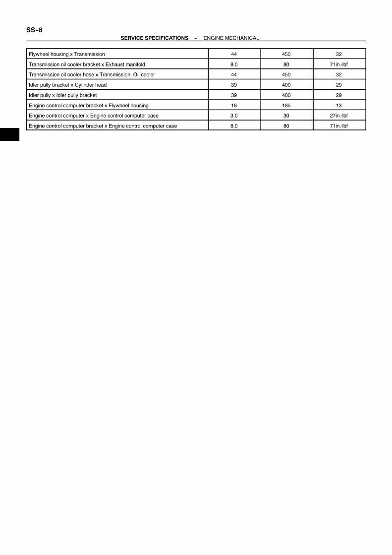
SS--8--SERVICE SPECIFICATIONS ENGINE MECHANICAL
Flywheel housing x Transmission 44 450 32
Transmission oil cooler bracket x Exhaust manifold 8.0 80 71in.⋅lbf
Transmission oil cooler hose x Transmission, Oil cooler 44 450 32
Idler pully bracket x Cylinder head 39 400 29
Idler pully x Idler pully bracket 39 400 29
Engine control computer bracket x Flywheel housing 18 185 13
Engine control computer x Engine control computer case 3.0 30 27in.⋅lbf
Engine control computer bracket x Engine control computer case 8.0 80 71in.⋅lbf

SS0HW--01
--SERVICE SPECIFICATIONS SFISS--9
SFISERVICE DATAFuel pressure
regulator
Fuel pressure 304 -- 343 kPa
(3.1 -- 3.5 kgf/cm2, 44 -- 50 psi)
Fuel pump Resistance at 20˚C (68˚F) 0.5 -- 30 Ω
Injector Resistance at 20˚C (68˚F)Injection volume
Difference between each cylinder
Fuel leakage
13.4 -- 14.2 Ω
60 -- 73 cm3 (3.7 -- 4.5 cu in.) per 15 sec.
13 cm3 (0.6 cu in.) or less
One drop or less per 12 minutes
MAF meter Resistance (THA -- E2) at --20˚C (--4˚F)at 20˚C (68˚F)at 60˚C (140˚F)
13.6 -- 18.4 kΩ
2.21 -- 2.69 kΩ
0.493 -- 0.667 kΩ
Throttle body Throttle body fully closed angle 4˚
Throttle position
sensor
Resistance (VC -- E2) at 20 ˚C (68 ˚F) 1.25 -- 2.35 kΩ
Accelerator pedal
position sensor
Resistance (VC -- E2) at 20 ˚C (68 ˚F)Standard throttle valve opening percentage
Sensor lever full--open position
1.64 -- 3.28 kΩ
60 % or more
Throttle control
motor w/ clutch
Motor resistance at 20 ˚C (68 ˚F)Clutch resistance at 20 ˚C (68 ˚F)
0.3 -- 100 Ω
4.2 -- 5.2 Ω
Camshaft
timing oil control
valve
Resistance at 20˚C (68˚F) 6.9 -- 7.9 Ω
VSV for acoustic
control induction
system (ACIS)
Resistance at 20˚C (68˚F) 33 -- 39 Ω
ECT sensor Resistance at --20˚C (--4˚F)0˚C (32˚F)20˚C (68˚F)40˚C (104˚F)60˚C (140˚F)80˚C (176˚F)
10 -- 20 kΩ
4 -- 7 kΩ
2 -- 3 kΩ
0.9 -- 1.3 kΩ
0.4 -- 0.7 kΩ
0.2 -- 0.4 kΩ
VVT sensor Resistance Cold
Hot
835 -- 1,400 Ω
1,060 -- 1,645 Ω
Fuel cut rpm Fuel return rpm 1,400 rpm
Water temperature
sender
Resistance at 55˚C (130˚F)at 82˚C (180˚F)
158 -- 202 Ω
63 -- 79 Ω
Oil pressure
sender
Resistance at 0 kgf/cm2 (0 psi)
at 1.8 kgf/cm2 (25 psi)
at 7.0kgf/cm2 (100 psi)
240 Ω
153 Ω
33.5 Ω

SS0HX--01
SS--10--SERVICE SPECIFICATIONS SFI
TORQUE SPECIFICATIONPart tightened N·m kgf·cm ft·lbf
Fuel pump bracket x Clinder block 29 300 21
Fuel pump assembly x Fuel pump bracket 7.0 70 60 in.·lbf
Fuel inlet pipe x Fuel pump 27.5 280 20
No.2 Fuel hose x Fuel pump 1.5 15 13 in.·lbf
Delivery pipe x Intake manifold 18 185 13
Thottle control cable bracket x Intake manifold 18 185 13
V--bank cover bracket x Engine hanger, Intake Manifold 7.5 80 69 in.·lbf
Fuel pressure pulsation damper x delivery pipe
for SST
39
33
400
340
29
24
Fuel pressure regulator x delivery pipe 29 300 21
FR Fuel pipe x delivery pipe 39 400 29
Throttle control motor x Throttle control motor cover 3.4 35 30 in.·lbf
Throttle control motor cover x Throttle body 3.4 35 30 in.·lbf
Accelerator pedal position sensor x Thrattle body 5.5 55 47 in.·lbf
Water bypass hose and pipe x Throttlebody 5.4 55 47 in.·lbf
Throttle body x Intake manifold 18 185 13
Camshaft oil control valve x Front bearing cap 7.5 80 66 in.·lbf
Intake air control valve x Upper intake manifold 8.5 85 75 in.·lbf
Actuator x Upper intake manifold 8.5 85 75 in.·lbf
Upper intake manifold x Lower intake manifold 18 185 13
ECT sensor x Front water bypass joint 20 200 14
Knock sensor x Cylinder block 44 450 33

SS0HJ--01
--SERVICE SPECIFICATIONS COOLINGSS--11
COOLINGSERVICE DATAThermostat Valve opening temperature
Valve lift at 85˚C (185˚F)69 -- 73˚C (156 -- 163˚F)10 mm (0.39 in.) or more

SS0HK--01
SS--12--SERVICE SPECIFICATIONS COOLING
TORQUE SPECIFICATIONPart tightened N·m kgf·cm ft·lbf
Engine drain plug x Cylinder block 24.5 250 18
Water pump x Cylinder block Stud Bolt and Nut
Bolt
18
21
185
215
13
15
Water inlet housing x Water pump 18 185 13
Water outlet x Water inlet housing 19 195 14
Sea water hose x Water inlet housing 2.5 25 22 in.·lbf
Sea water pump bracket x Fan bracket,Cylinder block 38 390 28
Sea water pump x Sea water pump bracket 18 185 13
Sea water pump pully x Sea water pump 98 1,000 72
Sea water pump x No.1 Sea water hose 2.5 25 22 in.·lbf

SS0HH--01
--SERVICE SPECIFICATIONS LUBRICATIONSS--13
LUBRICATIONSERVICE DATAOil pressure at idle speed
at 3,000 rpm
29 kPa (0.3 kgf/cm2, 4.2 psi) or more
294 -- 588 kPa (3.0 -- 6.0 kgf/cm2, 43 -- 85 psi)
Oil pump Tip clearance STD
Maximum
Side clearance STD
Maximum
Body clearance STD
Maximum
0.110 -- 0.240 mm (0.0043 -- 0.0094 in.)
0.35 mm (0.0138 in.)
0.030 -- 0.090 mm (0.0012 -- 0.0035 in.)
0.15 mm (0.0059 in.)
0.100 -- 0.175 mm (0.0039 -- 0.0069 in.)
0.30 mm (0.0118 in.)
SS0HI--01
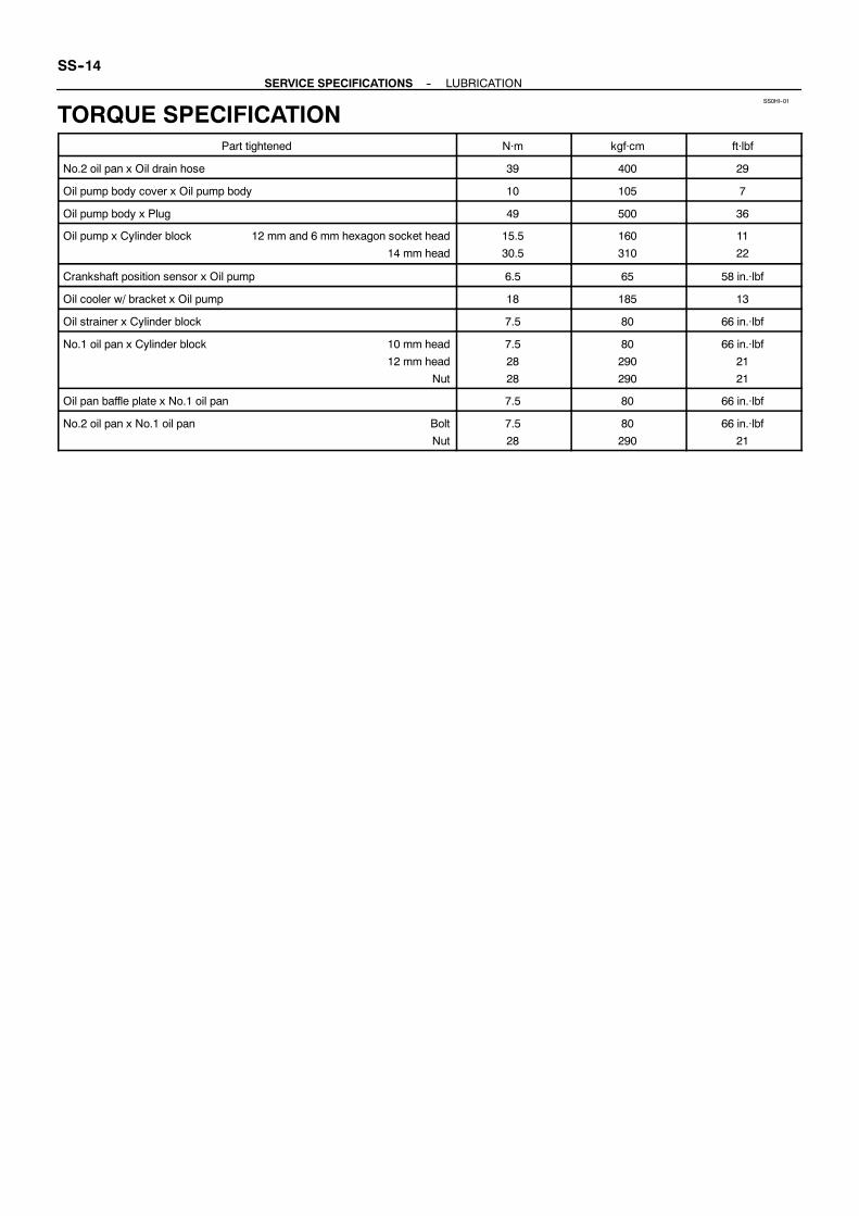
SS--14--SERVICE SPECIFICATIONS LUBRICATION
TORQUE SPECIFICATIONPart tightened N·m kgf·cm ft·lbf
No.2 oil pan x Oil drain hose 39 400 29
Oil pump body cover x Oil pump body 10 105 7
Oil pump body x Plug 49 500 36
Oil pump x Cylinder block 12 mm and 6 mm hexagon socket head
14 mm head
15.5
30.5
160
310
11
22
Crankshaft position sensor x Oil pump 6.5 65 58 in.·lbf
Oil cooler w/ bracket x Oil pump 18 185 13
Oil strainer x Cylinder block 7.5 80 66 in.·lbf
No.1 oil pan x Cylinder block 10 mm head
12 mm head
Nut
7.5
28
28
80
290
290
66 in.·lbf
21
21
Oil pan baffle plate x No.1 oil pan 7.5 80 66 in.·lbf
No.2 oil pan x No.1 oil pan Bolt
Nut
7.5
28
80
290
66 in.·lbf
21
SS0HQ--01
--SERVICE SPECIFICATIONS IGNITIONSS--15
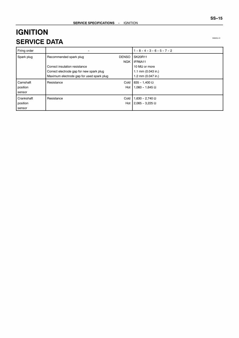
IGNITIONSERVICE DATAFiring order -- 1 -- 8 -- 4 -- 3 -- 6 -- 5 -- 7 -- 2
Spark plug Recommended spark plug DENSO
NGK
Correct insulation resistance
Correct electrode gap for new spark plug
Maximum electrode gap for used spark plug
SK20R11
IFR6A11
10 MΩ or more
1.1 mm (0.043 in.)
1.2 mm (0.047 in.)
Camshaft
position
sensor
Resistance Cold
Hot
835 -- 1,400 Ω
1,060 -- 1,645 Ω
Crankshaft
position
sensor
Resistance Cold
Hot
1,630 -- 2,740 Ω
2,065 -- 3,225 Ω

SS0HR--01
SS--16--SERVICE SPECIFICATIONS IGNITION
TORQUE SPECIFICATIONPart tightened N·m kgf·cm ft·lbf
Spark plug x Cylinder head 17.5 180 13
Ignition coil x Cylinder head cover 7.5 80 66 in.·lbf
Camshaft position sensor x LH cylinder head 7.5 80 66 in.·lbf
Crankshaft position sensor x Oil pump 6.5 65 58 in.·lbf

SS0HO--01
--SERVICE SPECIFICATIONS STARTINGSS--17
STARTINGSERVICE DATAStarter Rated voltage and output power
No--load characteristics Current
rpm
Brush length STD
Minimum
Spring installed load STD
Minimum
Commutator
Diameter STD
Minimum
Undercut depth STD
Minimum
Circle runout Maximum
Field frame
Shunt coil resistance at 20˚C (68˚F)Magnetic switch
Contact plate for wear Maximum
12 V 2.0 kW
100 A or less at 11.5 V
2,500 rpm or more
15.0 mm (0.591 in.)
9.0 mm (0.354 in.)
21.5 -- 27.5 N (2.2 -- 2.8 kgf, 4.8 -- 6.2 lbf)
12.7 N (1.3 kgf, 2.9 lbf)
35.0 mm (1.378 in.)
34.0 mm (1.339 in.)
0.7 mm (0.028 in.)
0.2 mm (0.008 in.)
0.05 mm (0.0020 in.)
1.5 -- 1.9 Ω
0.9 mm (0.035 in.)

SS0HP--01
SS--18--SERVICE SPECIFICATIONS STARTING
TORQUE SPECIFICATIONPart tightened N·m kgf·cm ft·lbf
Terminal 30 nut, Terminal C nut x Terminal bolt 17 170 13
End cover x Magnetic switch housing 3.6 37 32 in.·lbf
End cover x Brush holder 3.8 39 34 in.·lbf
Starter housing x Magnetic switch 9.3 95 82 in.·lbf
End cover with field frame x Magnetic switch 9.3 95 82 in.·lbf
Lead wire of field coil x Terminal C 5.9 60 52 in.·lbf
Wire clamp, Starter wire x Starter 9.81 98 87 in.·lbf
Starter x Cylinder block 39 400 29
Water bypass pipe x Cylinder block 18 185 13

SS0HM--01
--SERVICE SPECIFICATIONS CHARGINGSS--19
CHARGINGSERVICE DATABattery Voltage at 20˚C (68˚F) 12.5 -- 12.9 V
Generator Rated output
Rotor coil resistance at 20˚C (68˚F)Slip ring diameter STD
Minimum
Brush exposed length STD
Minimum
12 V -- 80 A
2.1 -- 2.5 Ω
14.2 mm -- 14.4 mm (0.559 -- 0.567 in.)
12.8 mm (0.504 in.)
10.5 mm (0.413 in.)
1.5 mm (0.059 in.)
Voltage
regulator
Regulating voltage at 25˚C (77˚F)at 115˚C (239˚F)
13.7 -- 14.8 V
13.2 -- 14.0 V
SS0HN--01
SS--20--SERVICE SPECIFICATIONS CHARGING
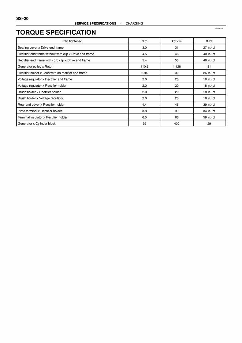
TORQUE SPECIFICATIONPart tightened N·m kgf·cm ft·lbf
Bearing cover x Drive end frame 3.0 31 27 in.·lbf
Rectifier end frame without wire clip x Drive end frame 4.5 46 40 in.·lbf
Rectifier end frame with cord clip x Drive end frame 5.4 55 48 in.·lbf
Generator pulley x Rotor 110.5 1,128 81
Rectifier holder x Lead wire on rectifier end frame 2.94 30 26 in.·lbf
Voltage regulator x Rectifier end frame 2.0 20 18 in.·lbf
Voltage regulator x Rectifier holder 2.0 20 18 in.·lbf
Brush holder x Rectifier holder 2.0 20 18 in.·lbf
Brush holder x Voltage regulator 2.0 20 18 in.·lbf
Rear end cover x Rectifier holder 4.4 45 39 in.·lbf
Plate terminal x Rectifier holder 3.8 39 34 in.·lbf
Terminal insulator x Rectifier holder 6.5 66 58 in.·lbf
Generator x Cylinder block 39 400 29

SERVICE SPECIFICATIONS
STANDARD BOLT SS--1. . . . . . . . . . . . . . . . . . . . . . . .
ENGINE MECHANICAL SS--3. . . . . . . . . . . . . . . . . . .
SFI SS--9. . . . . . . . . . . . . . . . . . . . . . . . . . . . . . . . . . . . .
COOLING SS--11. . . . . . . . . . . . . . . . . . . . . . . . . . . . . . .
LUBRICATION SS--13. . . . . . . . . . . . . . . . . . . . . . . . . . .
IGNITION SS--15. . . . . . . . . . . . . . . . . . . . . . . . . . . . . . .
STARTING SS--17. . . . . . . . . . . . . . . . . . . . . . . . . . . . . .
CHARGING SS--19. . . . . . . . . . . . . . . . . . . . . . . . . . . . .

DI2OC--01
Boat Brought to Workshop
Customer Problem Analysis P. DI--2
Problem Symptom ConfirmationIf the engine does not start, perform steps 10 and 12 first
Connect the OBD II scan tool or TOYOTA hand--held tester to DLC3 P. DI--3If the display indicates a communication fault in the tool, inspect DLC3 P. DI--3
Check DTC and Freezed Frame Data (Precheck)Record or Print DTC and Freezed Frame Data P. DI--3
Clear DTC and Freezed Frame Data P. DI--3
Visual Inspection
Setting the Check Mode Diagnosis P. DI--3
Symptom Simulation P. IN--9
DTC Chart P. DI--13
Problem Symptoms Table P. DI--19
Circuit Inspection P. DI--20
Adjustment, Repair
DTC Check P. DI--3
Titles inside are titles of pages in
in the bottom portion. See the indicatedpages for detailed explanations.
this manual with the page number indicated
Malfunctionoccurs.
Malfunction does not occur.
Parts Inspection
Check for Intermittent Problems P. DI--3
Identification of Problem
Confirmation Test
End
1
2
3
4
5
6
7
10
8
9
11
12
13
15
14
16
Normal Malfunction code.
17
Basic Inspection P. DI--3
--DIAGNOSTICS ENGINEDI--1
ENGINEHOW TO PROCEED WITH TROUBLESHOOTINGTroubleshoot in accordance with the procedure on the following page.

DI2OD--01
ENGINE CONTROL SYSTEM Check Sheet
Customer’s Name
Driver’s Name
Date BoatBrought in
License No.
Model and ModelYear
Hull No.
Engine Model
Hourmeter Reading hour
ProblemSym
ptoms
Engine doesnot Start
Difficult toStart
Poor Idling
PoorDriveability
Engine Stall
Others
Engine does not crank No initial combustion No complete combustion
Engine cranks slowlyOther
Incorrect first idle Idling rpm is abnormal High ( rpm) Low ( rpm)Rough idling Other
Hesitation Back fire Muffler explosion (after--fire) SurgingKnocking Other
Soon after starting After throttle lever depressedAfter throttle lever released Shifting from N to F or N to R
Other
Dates ProblemOccurred
Problem Frequency
ConditionWhen
ProblemOccurs
Weather
Engine Operation
Engine Temp.
OutdoorTemperature
Constant Sometimes ( times per day/month) Once onlyOther
Fine Cloudy Rainy Snowy Various/Other
Hot Warm Cool Cold (approx. ˚F/ ˚C)
Cold Warming up After warming up Any temp. Other
Starting Just after starting ( min.) Idling RacingDriving Constant speed Acceleration DecelerationOther
Condition of MIL Remains on Sometimes light up Does not light up
Normal Malfunction code(s) (code )Freezed frame data ( )
Normal Malfunction code(s) (code )Freezed frame data ( )
Normal Mode(Precheck)
Check Mode
DTC Inspection
Inspector’sName
Battery Switch On Off
DI--2--DIAGNOSTICS ENGINE
CUSTOMER PROBLEM ANALYSIS CHECK

DI2OE--01
MI0534
M24637
TOYOTA Hand--Held Tester
DLC3
--DIAGNOSTICS ENGINEDI--3
PRE--CHECK1. DIAGNOSIS SYSTEM(a) Description
When troubleshooting M1UZ engine, the only differencefrom the usual troubleshooting procedure is that you con-nect to the engine the OBD II scan tool complying withSAE J1978 or TOYOTA hand--held tester, and read offvarious data output from the engine’s ECM.The Malfunction Indicator Lamp (MIL) lighting up when amalfunction is detected, the applicable DiagnosticTrouble Codes (DTC) prescribed by SAE J2012 are re-corded in the ECMmemory (See page DI--13). If the mal-function dose not reoccur in 3 trips, the MIL goes off auto-matically but the DTCs remain recorded in the ECMmemory.To check the DTCs, connect the OBD II scan tool or TO-YOTA hand--held tester to Data Link Connector 3 (DLC3)on the engine. The OBD II scan tool or TOYOTA hand--held tester also enables you to erase theDTCs and checkfreezed frame data and various forms of engine data. (Foroperating instructions, see the OBD II scan tool’s instruc-tion book.)DTCs include SAE controlled codes and manufacturercontrolled codes. SAE controlled codes must be set asprescribed by the SAE, while manufacturer controlledcodes can be set freely by the manufacturer within theprescribed limits. (See DTC chart on page DI--13)The diagnosis system operates in normal mode duringnormal boat use. It also has a checkmode for techniciansto simulate malfunction symptoms and troubleshoot.Most DTCs use 2 trip detection logic* to prevent erro-neousdetection, and ensure thoroughmalfunction detec-tion. By switching the ECM to check mode when trouble-shooting, the technician can cause the MIL to light up fora malfunction that is only detected once or momentarily.(TOYOTA hand--held tester only) (See step 2)*2 trip detection logic:When a logic malfunction is first de-tected, the malfunction is temporarily stored in the ECMmemory. If the samemalfunction is detected again duringthe second drive test, this second detection causes theMIL to light up.The 2 trip repeats the same mode a 2nd time. (However,the IGswitchmust be turnedOFFbetween the1st trip and2nd trip.)

M09214
DLC3
DI--4--DIAGNOSTICS ENGINE
Freeze frame data:Freeze frame data records the engine conditions (fuelsystem, calculator load, engine coolant temperature, fueltrim etc.) when the malfunction is detected, when trouble-shooting it is useful for determining whether the enginewas running or stopped, the enginewarmed up or not, theair--fuel ratio lean or rich, etc. at the time of the malfunc-tion.
(b) Check the DLC3.The engine’s ECM uses the ISO 9141--2 communicationprotocol. The terminal arrangement of DLC3 complieswith SAE J1962 and matches the ISO 9141--2 format.
Terminal No. Connection / Voltage or Resistance Condition
7 Bus Line / Pulse generation During transmission
4 Chassis Ground↔ Body Ground / 1 Ω or less Always
16 Battery Positive↔ Body Ground / 9 ∼ 14 V Always
HINT:If your display shows ”UNABLE TO CONNECT TO ENGINE”when you have connected the cable of the OBD II scan tool orTOYOTA hand--held tester to DLC3, turned the ignition switchONandoperated the scan tool, there is a problemon theengineside or tool side.S If communication is normal when the tool is connected to
another engine, inspect DLC3 on the original engine.S If communication is still not possible when the tool is con-
nected to another engine, the problem is probably in thetool itself, so consult the Service Department listed in thetool’s instruction manual.

M16433
--DIAGNOSTICS ENGINEDI--5
2. INSPECT DIAGNOSIS (Normal Mode)(a) Check the MIL.
(1) TheMIL comesonwhen the ignition switch is turnedON and the engine is not running.
HINT:If theMIL does not light up, troubleshoot the combinationmeter.
(2) When the engine started, the MIL should go off. Ifthe lamp remains on, the diagnosis system has de-tected a malfunction or abnormality in the system.
(b) Check the DTC.NOTICE:TOYOTA hand--held tester only: When the diagnosis sys-tem is switched fromnormalmode to checkmode, it erasesall DTCs and freezed frame data recorded in normal mode.So before switching modes, always check the DTCs andfreezed frame data, and note them down.
(1) Prepare the OBD II scan tool (complying with SAEJ1978) or TOYOTA hand--held tester.
(2) Connect the OBD II scan tool or TOYOTA hand--held tester to DLC3 at the lower left of the instru-ment panel.
(3) Turn the ignition switch ON and push the OBD IIscan tool or TOYOTA hand--held tester switch ON.
(4) Use the OBD II scan tool or TOYOTA hand--heldtester to check the DTCs and freezed frame data,note them down. (For operating instructions, seethe OBD II scan tool’s instruction book.)
(5) See DI--13 to confirm the details of the DTCs.NOTICE:When simulating symptoms with an OBD II scan tool (ex-cluding TOYOTA hand--held tester) to check the DTCs, usenormal mode. For code on the DTC chart subject to ”2 tripdetection logic”, turn the ignition switch OFF after thesymptom is simulated the first time. Then repeat the simu-lation process again. When the problem has been simu-lated twice, the MIL lights up and the DTCs are recorded inthe ECM.(c) Clear the DTC.
TheDTCs and freezed frame data will be erased by eitheraction.(1) Operating theOBD II scan tool (complyingwithSAE
J1978) or TOYOTA hand--held tester to erase thecodes. (See the OBD II scan tool’s instruction bookfor operating instructions.)
(2) Disconnecting the battery terminals or EFI fuse.

FI3605
Flashing
ON
OFF
0.13 Seconds
DI--6--DIAGNOSTICS ENGINE
NOTICE:If the TOYOTA hand--held tester switches the ECM fromnormalmode to checkmode or vice--versa, or if the ignitionswitch is turned from ON to ACC or OFF during checkmode, the DTCs and freezed frame data will be erased.3. INSPECT DIAGNOSIS (Check Mode)TOYOTA hand--held tester only:Compared to the normal mode, the check mode has an in-creased sensitivity to detect malfunctions.Furthermore, the same diagnostic items which are detected inthe normal mode can also be detected in the check mode.(a) Check the DTC.
(1) Initial conditionsS Battery positive voltage 11V or more.S Throttle valve fully closed.S Transmission in ”N” position.
(2) Turn the ignition switch OFF.(3) Prepare the TOYOTA hand--held tester.(4) Connect the TOYOTA hand--held tester to the
DLC3 in the fuse box at the lower left of the instru-ment panel.
(5) Turn the ignition switch ON and push the TOYOTAhand--held tester switch ON.
(6) Switch the TOYOTAhand--held tester normalmodeto check mode. (Check that the MIL flashes.)
NOTICE:If the TOYOTA hand--held tester switches the ECM fromnormalmode to checkmode or vice--versa, or if the ignitionswitch is turned from ON to ACC or OFF during checkmode, the DTCs and freezed frame data will be erased.
(7) Start the engine. (TheMIL goes out after the enginestart.)
(8) Simulate the conditions of the malfunction de-scribed by the customer.
NOTICE:Leave the ignition switch ON until you have checked theDTCs, etc.
(9) After simulating the malfunction conditions, use theTOYOTA hand--held tester diagnosis selector tocheck the DTCs and freezed frame data, etc.
HINT:Take care not to turn the ignition switchOFF.Turning the ignitionswitch OFF switches the diagnosis system from check mode tonormal mode. so all DTCs, etc. are erased.
(10) After checking the DTC, inspect the applicable cir-cuit.

--DIAGNOSTICS ENGINEDI--7
4. FAIL--SAFE CHARTIf any of the following codes is recorded, the ECM enters fail--safe mode.
DTC No. Fail--Safe Operation Fail--Safe Deactivation Conditions
P0100 Ignition timing fixed at 5˚ BTDC Returned to normal condition
P0110 Intake air temperature is fixed at 20˚C (68˚F) Returned to normal condition
P0115 Engine coolant temperature is fixed at 80˚C (176˚F) Returned to normal condition
P0325
P0330Max. timing retardation Ignition switch OFF
P1300
P1305
P1310
P1315
P1320
P1325
P1330
P1340
Fuel cut Returned to normal condition
5. CHECK FOR INTERMITTENT PROBLEMSTOYOTA HAND--HELD TESTER only:By putting the engine’s ECM in check mode, 1 trip detection logic is possible instead of 2 trip detection logicand sensitivity to detect open circuits is increased. This makes it easier to detect intermittent problems.
(1) Clear the DTCs.(2) Set the check mode.(3) Perform a simulation test (See page IN--9).(4) Check the connector and terminal (See page IN--19).(5) Handle the connector (See page IN--19).
6. BASIC INSPECTIONWhen the malfunction code is not confirmed in the DTC check, troubleshooting should be performed in theorder for all possible circuits to be considered as the causes of the problems. In many cases, by carryingout the basic engine check shown in the following flow chart, the location causing the problem can be foundquickly and efficiently. Therefore, use of this check is essential in engine troubleshooting.
1 Is battery positive voltage 11 V or more when engine is stopped?
NO Charge or replace battery.
YES

M00689Outside Inside
YellowPainted Mark
DI--8--DIAGNOSTICS ENGINE
2 Is engine cranked?
NO Proceed to page ST--16, ST--18 andcontinue to troubleshoot.
YES
3 Does engine start?
NO Go to step 7.
YES
4 Check air filter.
PREPARATION:Remove the air filter.CHECK:Visual check that the air filter is not dirty or excessive oily.HINT:If necessary, clean the filter using water or kerosene. Aftercleaning the filter, blow it dry using compressed air.
NG Repair or replace
NOTICE:Install the air filter into the intake air connector while facingthe yellow painted mark upward.
OK

M03244M03243
DLC3
TCCG
SST
--DIAGNOSTICS ENGINEDI--9
5 Check idle speed.
PREPARATION:(a) Warm up the engine to normal operating temperature.(b) Switch off all accessories.(c) Switch off air conditioning.(d) Shift transmission into ”N” position.(e) Connect the OBD II scan tool or TOYOTA hand--held tester to the DLC3 on the vehicle.CHECK:Use CURRENT DATA to check the idle speed.OK:
Idle speed: 650 ∼ 750 rpm
NG Proceed to problem symptoms table onpage DI--19.
OK
6 Check ignition timing.
PREPARATION:(a) Warm up the engine to normal operating temperature.(b) Shift transmission into ”N” position.(c) Keep the engine speed at idle.(d) Using SST, connect terminals TC and CG of the DLC3.
SST 09843 -- 18040(e) Using a timing light, connect the tester to the ignition coil
connector wire (See page EM--7).CHECK:Check ignition timing.OK:
Ignition timing: 10˚ BTDC at idle
NG Proceed to page IG--1 and continue totroubleshoot.
OK
Proceed to problem symptoms table on pageDI--19.

M02886
DI--10--DIAGNOSTICS ENGINE
7 Check fuel pressure.
PREPARATION:(a) Be sure that enough fuel is in the tank.(b) Connect the TOYOTA hand--held tester to the DLC3.(c) Turn the ignition switchONandpush TOYOTAhand--held
tester main switch ON.(d) Use ACTIVE TEST mode to operate the fuel pump.(e) Please refer to the TOYOTA hand--held tester operator’s
manual for further details.(f) If you have no TOYOTA hand--held tester, connect the
positive (+) and negative (--) leads from the battery to thefuel pump connector (See page SF--1).
CHECK:Check that there is pressure in the fuel inlet hose from the fuelfilter.HINT:When checking the fuel pressure pulsation damper, remove thecover on it.When pressure is applied, the button on the fuel pressurepulsation damper rises.
NG Proceed to page SF--5 and continue totroubleshoot.
OK

M02753
--DIAGNOSTICS ENGINEDI--11
8 Check for spark.
PREPARATION:(a) Remove the ignition coil from the spark plug.(b) Remove the spark plug.(c) Install the spark plug to the ignition coil.(d) Disconnect the injector connector.(e) Ground the spark plug.CHECK:Check if spark occurs while engine is being cranked.NOTICE:To prevent excess fuel being injected from the injectorsduring this test, don’t crank the engine formore than 5 ∼ 10seconds at a time.
NG Proceed to page IG--1 and continue totroubleshoot.
OK
Proceed to problem symptoms table on pageDI--19.
7. ENGINE OPERATING CONDITIONNOTICE:The values given below for ”Normal Condition” are representative values, so a boat may still be nor-mal even if its value varies from those listed here. So do not decide whether a part is faulty or notsolely according to the ”Normal Condition” here.(a) CARB mandated signals.
TOYOTA hand--held tester display Measurement Item Normal Condition*
CALC LOAD
Calculator Load:
Current intake air volume as a proportion of max.
intake air volume
Idling: 13.9 ∼ 19.7%
Racing without load (2,500rpm): 13.9 ∼ 19.7%
COOLANT TEMP Engine Coolant Temp. Sensor Value After warming up: 65 ∼ 80˚C(149∼176˚F)
ENGINE SPD Engine Speed Idling: 650 ∼ 750 rpm
IGN ADVANCEIgnition Advance:
Ignition Timing of Cylinder No. 1Idling: BTDC 5 ∼ 15˚
INTAKE AIR Intake Air Temp. Sensor Value Equivalent to ambient temp.
MAF Air Flow Rate Through Mass Air Flow Meter
Idling: 4.0 ∼ 5.6 gm/sec.
Racing without load (2,500 rpm):
13.2 ∼ 18.7 gm/sec.
THROTTLE POS
Voltage Output of Throttle Position Sensor
Calculated as a percentage:
0 V→ 0 %, 5 V→ 100 %
Throttle fully closed: 8 ∼ 20 %
Throttle fully open: 64 ∼ 96 %
∗: If no conditions are specifically stated for ”ldling”, it means the shift lever is at N position and all accessoryswitches are OFF.

DI--12--DIAGNOSTICS ENGINE
(b) TOYOTA Enhanced Signals.
TOYOTA hand--held tester display Measurement Item Normal Condition*
MISFIRE RPM Engine RPM for first misfire range Misfire 0: 0 rpm
MISFIRE LOAD Engine load for first misfire range Misfire 0: 0 g/r
INJECTOR Fuel injection time for cylinder No.1 Idling: 1.8 ∼ 3.2 ms
STARTER SIG Starter Signal Cranking: ON
CTP Closed Throttle Position Throttle fully closed: ON
FC IDLFuel Cut Idle: Fuel cut when throttle valve fully
closed, during decelerationFuel cut operating: ON
FC TAU Fuel Cut TAU: Fuel cut during very light load Fuel cut operating: ON
CYL#1 ∼ CYL#8 Abnormal revolution variation for each cylinder 0 %
IGNITIONTotal number of ignition for every 1,000 revolu-
tions0 ∼ 4,000
FUEL PUMP Fuel Pump Signal Idling: ON
THROTTLE POS #2 Throttle position sensor No.2 output voltageThrottle fully closed: 2.0 ∼ 2.9 V
Throttle fully open: 4.6 ∼ 5.0 V
ACCEL POSAccelerator pedal position sensor No.1 output
voltage
Accelerator released: 0.25 ∼ 0.9 V
Accelerator depressed: 3.2 ∼ 4.8 V
ACCEL POS #2Accelerator pedal position sensor No.2 output
voltage
Accelerator released: 1.8 ∼ 2.7 V
Accelerator depressed: 4.7 ∼ 5.0 V
THROTTLE TARGET POS Target position of throttle valve Idling: 0.4 ∼ 1.1 V
THROTTLE OPEN DUTY Throttle motor opening duty ratio
Throttle fully closed: 0 %
When accelerator pedal is depressed,
duty ratio is increased
THROTTLE CLOSE DUTY Throttle motor closed duty ratio
Throttle fully closed: 0 %
When accelerator pedal is quick released,
duty ratio is increased
THROTTLE MOTOR CTL Whether or not throttle motor control is permitted Idling: ON
THROTTLE CLUTCH CTLWhether or not magnetic clutch control
is permittedIdling: ON
+BMWhether or not electric throttle control system
power is inputtedIdling: ON
ACCEL IDLWhether or not accelerator pedal position sensor
is detecting idleIdling: ON
THROTTLE IDLWhether or not throttle position sensor is
detecting idleIdling: ON
FAIL #1 Whether or not fail safe function is executed ETCS is failed: ON
FAIL #2 Whether or not fail safe function is executed ETCS is failed: ON
THROTTLE LEAN VALUE Throttle fully closed learning value 0.4 ∼ 0.8 V
ACCEL LEAN VALUE Accelerator fully closed learning value 0.4 ∼ 0.8 V
THROTTLE MOTOR Throttle motor control current Idling: 0 ∼ 3.0 A
ETCS MAG CLUTCH Magnetic clutch control current 0.8 ∼ 1.0 A
∗: If no conditions are specifically stated for ”ldling”, it means the shift lever is at N position and all accessoryswitches are OFF.

DI2PO--01
--DIAGNOSTICS ENGINEDI--13
DIAGNOSTIC TROUBLE CODE CHART1. SAE ControlledHINT:Parameters listed in the chart may not be exactly the same as your reading due to the type of instrumentor other factors.If a malfunction code is displayed during the DTC check in check mode, check the circuit for that code listedin the table below. For details of each code, turn to the page referred to under the ’’See Page’’ for the respec-tive ’’DTC No.’’ in the DTC chart.
DTC No.
(See Page)Detection Item Trouble Area
MIL*1
(flashing*2)Memory
P0100
(DI--20)
Mass Air Flow Circuit
Malfunction
SOpen or short in mass air flow meter circuit
SMass air flow meter
SECM
f
(31)f
P0110
(DI--24)
Intake Air Temp. Circuit
Malfunction
SOpen or short in intake air temp. sensor circuit
S Intake air temp. sensor (inside mass air flow meter)
SECM
f
*3f
P0115
(DI--29)
Engine Coolant Temp. Circuit
Malfunction
SOpen or short in engine coolant temp. sensor circuit
SEngine coolant temp. sensor
SECM
f
(24)f
P0120
(DI--33)
Throttle/Pedal Position
Sensor/Switch ”A” Circuit
Malfunction
SOpen or short in throttle position sensor circuit
SThrottle position sensor
SECM
f
(41)f
P0121
(DI--39)
Throttle/Pedal Position
Sensor/Switch ”A” Circuit
Range/Performance Problem
SThrottle position sensor
SECM
f
(41)f
P0325
(DI--40)
Knock Sensor 1 Circuit
Malfunction
SOpen or short in knock sensor 1 circuit
SKnock sensor 1 (looseness)
SECM
f
(52)f
P0330
(DI--40)
Knock Sensor 2 Circuit
Malfunction
SOpen or short in knock sensor 2 circuit
SKnock sensor 2 (looseness)
SECM
f
(55)f
P0335
(DI--44)
Crankshaft Position Sensor
”A” Circuit Malfunction
SOpen or short in crankshaft position sensor circuit
SCrankshaft position sensor
SStarter
SECM
f
(12.13)f
P0340
(DI--47)
Camshaft Position Sensor
Circuit Malfunction
SOpen or short in camshaft position sensor circuit
SCamshaft position sensor
SStarter
SECM
f
(12)f
*1: MIL lights up while engine running,*2: MIL flashing by switching the ECM to check mode*3: MIL lights up only (check engine lamp lights up)

DI--14--DIAGNOSTICS ENGINE
2. Manufacturer Controlled
DTC No.
(See Page)Detection Item Trouble Area
MIL*1
(flashing*2)Memory
P1120
(DI--49)
Accelerator Pedal Position
Sensor Circuit Malfunction
SOpen or short in accelerator pedal position sensor circuit
SAccelerator pedal position sensor
SECM
f
(19)f
P1121
(DI--54)
Accelerator Pedal Position
Sensor Range/Performance
Problem
SAccelerator pedal position sensor
SECM
f
(19)f
P1125
(DI--55)
Throttle Control Motor Circuit
Malfunction
SOpen or short in throttle control motor circuit
SThrottle control motor
SECM
f
(89)f
P1126
(DI--58)
Magnetic Clutch Circuit
Malfunction
SOpen or short in magnetic clutch circuit
SMagnetic clutch
SECM
f
(89)f
P1127
(DI--61)
ETCS Actuator Power Source
Circuit Malfunction
SOpen in ETCS (electric throttle control system) power source
circuit
SECM
f
(89)f
P1128
(DI--63)
Throttle Control Motor Lock
Malfunction
SThrottle control motor
SThrottle body
SECM
f
(89)f
P1129
(DI--65)
Electric Throttle Control
System Malfunction
SElectric throttle control system
SECM
f
(89)f
P1300
(DI--66)
Igniter Circuit Malfunction
(No.1)
SOpen or short in IGF1 or IGT1 circuit from No.1 ignition coil
with igniter to ECM
SNo.1 ignition coil with igniter
SECM
f
(14)f
P1305
(DI--66)
Igniter Circuit Malfunction
(No.2)
SOpen or short in IGF2 or IGT2 circuit from No.2 ignition coil
with igniter to ECM
SNo.2 ignition coil with igniter
SECM
f
(15)f
P1310
(DI--66)
Igniter Circuit Malfunction
(No.3)
SOpen or short in IGF2 or IGT3 circuit from No.3 ignition coil
with igniter to ECM
SNo.3 ignition coil with igniter
SECM
f
(14)f
P1315
(DI--66)
Igniter Circuit Malfunction
(No.4)
SOpen or short in IGF1 or IGT4 circuit from No.4 ignition coil
with igniter to ECM
SNo.4 ignition coil with igniter
SECM
f
(14)f
P1320
(DI--66)
Igniter Circuit Malfunction
(No.5)
SOpen or short in IGF2 or IGT5 circuit from No.5 ignition coil
with igniter to ECM
SNo.5 ignition coil with igniter
SECM
f
(14)f
P1325
(DI--66)
Igniter Circuit Malfunction
(No.6)
SOpen or short in IGF1 or IGT6 circuit from No.6 ignition coil
with igniter to ECM
SNo.6 ignition coil with igniter
SECM
f
(14)f
*1: MIL lights up while engine running,*2: MIL flashing by switching the ECM to check mode
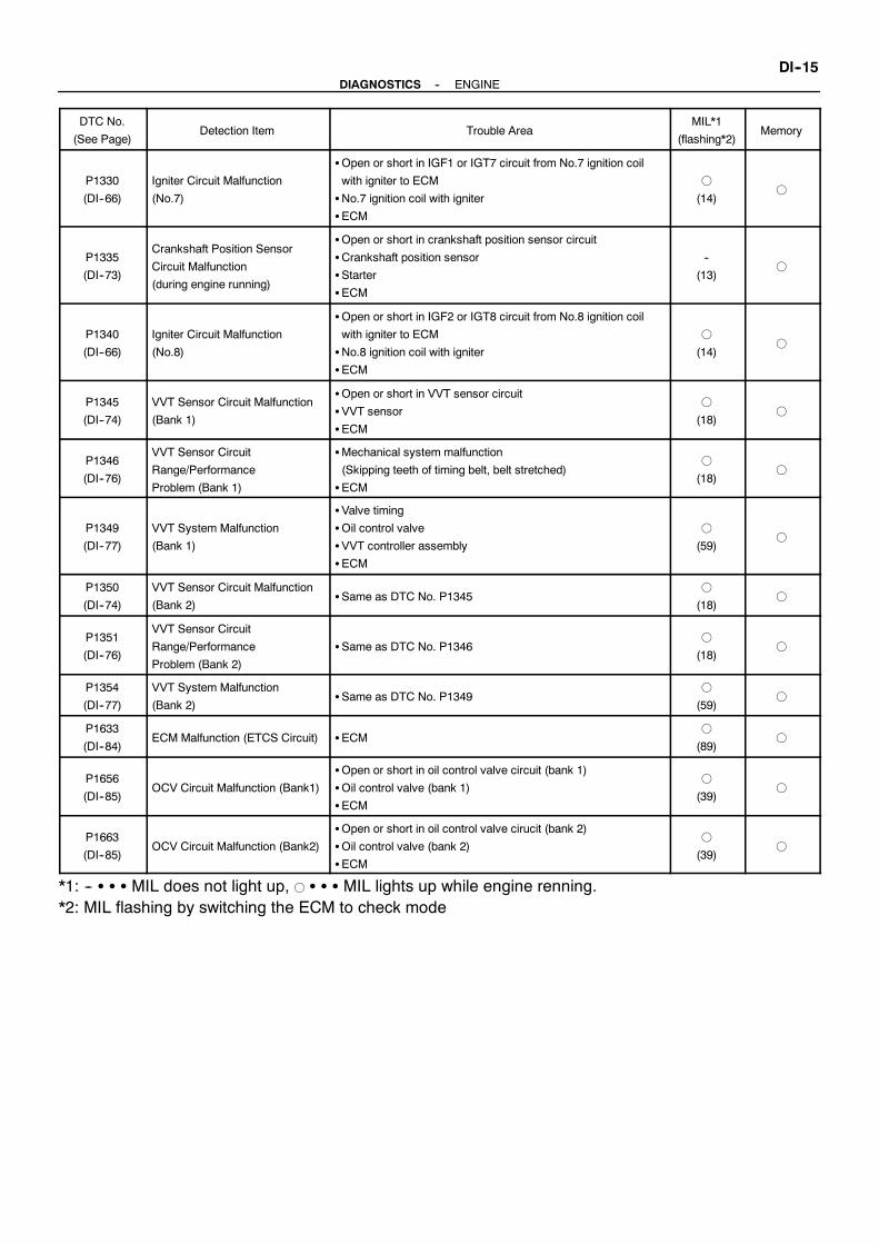
--DIAGNOSTICS ENGINEDI--15
DTC No.
(See Page)Detection Item Trouble Area
MIL*1
(flashing*2)Memory
P1330
(DI--66)
Igniter Circuit Malfunction
(No.7)
SOpen or short in IGF1 or IGT7 circuit from No.7 ignition coil
with igniter to ECM
SNo.7 ignition coil with igniter
SECM
f
(14)f
P1335
(DI--73)
Crankshaft Position Sensor
Circuit Malfunction
(during engine running)
SOpen or short in crankshaft position sensor circuit
SCrankshaft position sensor
SStarter
SECM
--
(13)f
P1340
(DI--66)
Igniter Circuit Malfunction
(No.8)
SOpen or short in IGF2 or IGT8 circuit from No.8 ignition coil
with igniter to ECM
SNo.8 ignition coil with igniter
SECM
f
(14)f
P1345
(DI--74)
VVT Sensor Circuit Malfunction
(Bank 1)
SOpen or short in VVT sensor circuit
SVVT sensor
SECM
f
(18)f
P1346
(DI--76)
VVT Sensor Circuit
Range/Performance
Problem (Bank 1)
SMechanical system malfunction
(Skipping teeth of timing belt, belt stretched)
SECM
f
(18)f
P1349
(DI--77)
VVT System Malfunction
(Bank 1)
SValve timing
SOil control valve
SVVT controller assembly
SECM
f
(59)f
P1350
(DI--74)
VVT Sensor Circuit Malfunction
(Bank 2)SSame as DTC No. P1345
f
(18)f
P1351
(DI--76)
VVT Sensor Circuit
Range/Performance
Problem (Bank 2)
SSame as DTC No. P1346f
(18)f
P1354
(DI--77)
VVT System Malfunction
(Bank 2)SSame as DTC No. P1349
f
(59)f
P1633
(DI--84)ECM Malfunction (ETCS Circuit) SECM
f
(89)f
P1656
(DI--85)OCV Circuit Malfunction (Bank1)
SOpen or short in oil control valve circuit (bank 1)
SOil control valve (bank 1)
SECM
f
(39)f
P1663
(DI--85)OCV Circuit Malfunction (Bank2)
SOpen or short in oil control valve cirucit (bank 2)
SOil control valve (bank 2)
SECM
f
(39)f
*1: -- S S S MIL does not light up, f S S S MIL lights up while engine renning.*2: MIL flashing by switching the ECM to check mode

DI2OF--01
M03841
Mass Air Flow Meterwith Intake Air Temp.Sencor
Accelerator PedalPosition Sensor
Engine CoolantTemp. Sensor
VSV for ACIS
VVT Sensor(Bank2)
Ignition Coilwith Igniter
Knock Sensor(Bank2)
Injector
DLC 3
ECM
Neutral Position Switch
EFI Main Relay
Knock Sensor(Bank 1)VVT Sensor
(Bank 1)
Throttle PositionSensor
Crankshaft PositionSensor
Oil Control Valve(Bank 1)
Throttle Control Motorwith Magnetic Clutch
Oil Control Valve(Bank 2)
Camshaft PositionSensor
DI--16--DIAGNOSTICS ENGINE
PARTS LOCATION

DI1L7--01
A01888
ECM Terminals
12456789 3
101112131416 151920 171821
22232425262728293031
12456 37
89101112131416 15
1920 171821222324
12456 3
789101112
14 13151617
12346 5789
101112131416 1519 1718
20212225262728 2324
1234567
89101112131415
1718 1619202122
1235678 4910111213
1416 1519 17182021222526 2324
E14 E13 E12 E11 E15 E16
E14 E13 E12
E11 E15 E16
--DIAGNOSTICS ENGINEDI--17
TERMINALS OF ECM
Symbols (Terminals No.) Wiring Color Condition STD Voltage (V)
BATT (E15--1) -- E1 (E13--17) B↔W--BAl 9 14
+BM (E15--7) -- E1 (E13--17) L↔W--BAlways 9 ∼ 14
IGSW (E15--9) -- E1 (E13--17) B↔W--B
+B (E15--16) -- E1 (E13--17) W↔W--B IG switch ON 9 ∼ 14
+B1 (E15--8) -- E1 (E13--17) W↔W--B
IG switch ON 9 14
VC (E13--2) -- E2 (E13--18) L↔ BR IG switch ON 4.5 ∼ 5.5
VTA (E13 13) E2 (E13 18) Y BR
IG switch ON
Throttle lever fully closed0.4 ∼ 1.0
VTA (E13--13) -- E2 (E13--18) Y↔ BRIG switch ON
Throttle lever fully closed3.2 ∼ 4.8
VTA2 (E13 20) E2 (E13 18) Y B BR
IG switch ON
Throttle lever fully closed2.0 ∼ 2.9
VTA2 (E13--20) -- E2 (E13--18) Y--B↔ BRIG switch ON
Throttle lever fully closed4.6 ∼ 5.1
VPA (E13 21) E2 (E13 18) R BR
IG switch ON
Throttle lever fully closed0.3 ∼ 0.9
VPA (E13--21) -- E2 (E13--18) R↔ BRIG switch ON
Throttle lever fully closed3.2 ∼ 4.8
VPA2 (E13 9) E2 (E13 18) R B BR
IG switch ON
Throttle lever fully closed1.8 ∼ 2.7
VPA2 (E13--9) -- E2 (E13--18) R--B↔ BRIG switch ON
Throttle lever fully closed4.7 ∼ 5.1
VG (E13--10) -- EVG (E13--19) L--Y↔ G--W Idling, N position 0.5 ∼ 3.0
THA (E13--22) -- E2 (E13--18) Y--B↔ BR Idling, Intake air temp. 20˚C (68˚F) 0.5 ∼ 3.4
THW (E13--14) -- E2 (E13--18) R--L↔ BR Idling, Engine coolant temp. 80˚C (176˚F) 0.2 ∼ 1.0
STA (E11--17) -- E1 (E13--17) Y--R↔W--B Shift lever position N position, ignition switch START 6.0 or more

DI--18--DIAGNOSTICS ENGINE
Symbols (Terminals No.) Wiring Color Condition STD Voltage (V)
#1 (E13--5) -- E01 (E14--21)
#2 (E13--6) -- E01 (E14--21)
#3 (E14--1) -- E01 (E14--21)
#4 (E14--2) -- E01 (E14--21)
Y↔W--B
B↔W--B
L↔W--B
R↔W--B
IG switch ON 9 ∼ 14
#4 (E14--2) -- E01 (E14--21)
#5 (E14--3) -- E01 (E14--21)
#6 (E14--4) -- E01 (E14--21)
#7 (E14--5) -- E01 (E14--21)
#8 (E14--6) -- E01 (E14--21)
R↔W--B
G↔W--B
R--L↔W--B
W↔W--B
B--W↔W--B
Idling Pulse generation
IGT1 (E14--11) -- E1 (E13--17)
IGT2 (E14--12) -- E1 (E13--17)
IGT3 (E14--13) -- E1 (E13--17)
IGT4 (E14--14) -- E1 (E13--17)
IGT5 (E14--15) -- E1 (E13--17)
IGT6 (E14--16) -- E1 (E13--17)
IGT7 (E14--25) -- E1 (E13--17)
IGT8 (E14--26) -- E1 (E13--17)
Y↔W--B
B↔W--B
L↔W--B
R↔W--B
G↔W--B
R--L↔W--B
W↔W--B
B--W↔W--B
IdlingPulse generation
(See page DI--66)
IGF1 (E1 2 ) E1 (E13 1 ) Y W BIG switch ON 4.5 ∼ 5.5
IGF1 (E14--27) -- E1 (E13--17)
IGF2 (E14--28) -- E1 (E13--17)
Y↔W--B
Y↔W--B IdlingPulse generation
(See page DI--66)
G2 (E14--10) -- NE-- (E14--22) B↔WIdli
Pulse generation
NE+ (E14--23) -- NE-- (E14--22) B↔WIdling
Pulse generation
(See page DI--44)
MREL (E15--10) -- E1 (E13--17) B↔W--B IG switch ON 9 ∼ 14
FC (E15--5) -- E1 (E13--17) G↔W--B IG switch ON 9 ∼ 14
KNKL (E14--18) -- E1 (E13--17) B↔W--BM i t i i d t 4 000 ft i
Pulse generation
KNKR (E14--17) -- E1 (E13--17) GR↔W--BMaintain engine speed at 4,000 rpm after warming up
Pulse generation
(See page DI--40)
TC (E11--5) -- E1 (E13--17) LG↔W--B IG switch ON 9 ∼ 14
W (E15 6) E1 (E13 17) P W BIdling 9 ∼ 14
W (E15--6) -- E1 (E13--17) P↔W--BIG switch ON Below 3.0
VVL+ (E13--16)
-- VVL-- (E13--24)P↔ V
IdliPulse generation
VVR+ (E13--15)
-- VVR-- (E13--23)Y↔ L
IdlingPulse generation
(See page DI--74)
OCV+ (E14--20)
-- OCV-- (E14--19)L--W↔ L--B
IG it h ONPulse generation
OCR+ (E11--19)
-- OCR-- (E11--28)G--W↔G--B
IG switch ONPulse generation
(See page DI--77)
ACIS (E14 29) E01 (E14 21) L W W BIG switch ON 9 ∼ 14
ACIS (E14--29) -- E01 (E14--21) L--W↔W--BEngine speed between 2,500 rpm and 4,000 rpm Below 3.0
CL+ (E12--12) -- CL-- (E13--8) G--W↔ B--R IdlingPulse generation
(See page DI--58)
M+ (E14--8) -- E1 (E13--17)
M-- (E14--7) -- E1 (E13--17)
G↔W--B
R↔W--BIdling
Pulse generation
(See page DI--55)
SIL (E15--11) -- E1 (E13--17) L↔W--B During transmission Pulse generation

DI2OH--01
--DIAGNOSTICS ENGINEDI--19
PROBLEM SYMPTOMS TABLESymptom Suspect Area See page
Engine does not crank (Does not start)1. Starter
2. Starter relay
ST--16
ST--18
No initial combustion (Does not start)
1. ECM power source circuit
2. Circuit opning relay
3. Fuel pump
DI--91
SF--59
SF--5
No complete combustion (Does not start)1. Circuit opning relay
2. Fuel pump
SF--59
SF--5
Under normal condition (Difficult to start)
1. Starter signal circuit
2. Circuit opning relay
3. Fuel pump
4. Compression
DI--88
SF--59
SF--5
EM--1
Cold engine (Difficult to start)
1. Starter signal circuit
2. Circuit opning relay
3. Fuel pump
DI--88
SF--59
SF--5
Hot engine (Difficult to start)
1. Starter signal circuit
2. Circuit opning relay
3. Fuel pump
DI--88
SF--59
SF--5
High engine idle speed (Poor idling) 1. ECM power source circuit DI--91
Low engine idle speed (Poor idling)1. Circuit opning relay
2. Fuel pump
SF--59
SF--5
Rough idling (Poor idling)
1. Compression
2. Circuit opning relay
3. Fuel pump
EM--1
SF--59
SF--5
Hunting (Poor idling)
1. ECM power source circuit
2. Circuit opning relay
3. Fuel pump
DI--91
SF--59
SF--5
Hesitation/Poor acceleration (Poor driveability)1. Circuit opning relay
2. Fuel pump
SF--59
SF--5
Surging (Poor driveability)1. Circuit opning relay
2. Fuel pump
SF--59
SF--5
Soon after starting (Engine stall)1. Circuit opning relay
2. Fuel pump
SF--59
SF--5

DI2OI--01
A00435
Power Transistor
Platinum Hot Wire
OutputVoltage
Thermistor
A B
Platinum Hot Wire Thermistor
B+
FI6929S05741
DI--20--DIAGNOSTICS ENGINE
CIRCUIT INSPECTION
DTC P0100 Mass Air Flow Circuit Malfunction
CIRCUIT DESCRIPTION
Themass air flowmeter uses a platinum hot wire. The hot wire air flowmeter consists of a platinum hot wire,thermistor and a control circuit installed in a plastic housing. The hot wire air flowmeterworks on the principlethat the hot wire and thermistor located in the intake air bypass of the housing detect any changes in theintake air temperature.The hot wire is maintained at the set temperature by controlling the current flow through the hot wire. Thiscurrent flow is ten measured as the output voltage of the mass air flow meter.The circuit is constructed so that the platinum hot wire and thermistor provide a bridge circuit, with the powertransistor controlled so that the potential of A and B remains equal to maintain the set temperature.
DTC No. DTC Detecting Condition Trouble Area
Open or short in mass air flow meter circuit with more
than 3 sec. engine speed 4,000 rpm or less SOpen or short in mass air flow meter circuit
P0100 Open or short in mass air flow meter circuit with more than
3 sec. engine speed 4,000 rpm or more
(2 trip detection logic)
SOpen or short in mass air flow meter circuit
SMass air flow meter
SECM
HINT:After confirming DTC P0100 use the OBD II scan tool or TOYOTA hand--held tester to confirm the mass airflow ratio from CURRENT DATA.
Mass Air Flow Value (gm/sec.) Malfunction
Approx. 0.0SMass air flow meter power source circuit open
SVG circuit open or short
271.0 or more SEVG circuit open

M02401
EFI No.3
EFIMAINRelay
EFI No.2
ECM
10E15
10E13
19E13
MREL
B+
VG
EVG
5
3
L--Y
G--W
MassAir FlowMeter
4
B--R
4
1
2
3
EB
ALT
W--B
Battery
CircuitBreaker120A
B--R
E2G
VG
B
W
--DIAGNOSTICS ENGINEDI--21
WIRING DIAGRAM
INSPECTION PROCEDURE
HINT:Read freeze frame data using TOYOTAhand--held tester or OBD II scan tool. Because freeze frame recordsthe engine conditions when the malfunction is detected, when troubleshooting it is useful for determiningwhether the engine was running or stopped, the engine warmed up or not, the air--fuel ratio lean or rich, etc.at the time of the malfunction.
1 Connect OBD II scan tool or TOYOTA hand--held tester, and read value of massair flow rate.
PREPARATION:(a) Connect the OBD II scan tool or TOYOTA hand--held tester to the DLC3.(b) Turn the ignition switch ON and push the OBD II scan tool or TOYOTA hand--held tester main switch
ON.(c) Start the engine.CHECK:Read mass air flow rate on the OBD II scan tool or TOYOTA hand--held tester.RESULT:
Type I Type II
Mass air flow rata (gm/sec.) 0.0 271.0 or more
Type I Go to step 2.
Type II Go to step 5.

A00436
ON
4(+)BE6653S05337
M01945
VG (+)
DI--22--DIAGNOSTICS ENGINE
2 Check voltage of mass air flow meter power source.
PREPARATION:(a) Disconnect the mass air flow meter connector.(b) Turn the ignition switch ON.CHECK:Measure voltage between terminal 4 of the mass air flowmeterconnector and body ground.OK:
Voltage: 9 ∼ 14 V
NG Check for open in harness and connectorbetween EFI main relay (Marking: EFI) andmass air flow meter (See page IN--19).
OK
3 Check voltage between terminals VG of ECM connector and body ground.
PREPARATION:(a) Remove the wire harness boot.(b) Start the engine.CHECK:Measure voltage between terminal VG of the ECM connectorand body ground while engine is idling.OK:
Voltage:0.5 ∼ 3.0 V (N position)
OK Check and replace ECM (See page IN--19).
NG

M01946
EVG
--DIAGNOSTICS ENGINEDI--23
4 Check for open and short in harness and connector between mass air flow meterand ECM (See page IN--19).
NG Repair or replace harness or connector.
OK
Replace mass air flow meter.
5 Check continuity between terminal EVG of ECM connector and body ground.
PREPARATION:Remove the wire harness boot.CHECK:Check continuity between terminal EVG of the ECM connectorand body ground.OK:
Continuity (1 Ω or less)
NG Check and replace ECM (See page IN--19).
OK
6 Check for open in harness and connector between mass air flow meter and ECM(See page IN--19).
NG Repair or replace harness or connector.
OK
Replace mass air flow meter.

FI4741
(fig. 1)
Acceptable
ResistancekΩ
-- 20 0 20 40 60 80 100(-- 4) 32 68 104 140 176 212
30
20
10
5
3
2
1
0.5
0.3
0.2
0.1
Temperature˚C (˚F)
DI--24--DIAGNOSTICS ENGINE
DTC P0110 Intake Air Temp. Circuit Malfunction
CIRCUIT DESCRIPTION
The intake air temp. sensor is built into the mass air flow meterand senses the intake air temperature.A thermistor built in the sensor changes the resistance valueaccording to the intake air temperature.The lower the intake air temperature, the greater the thermistorresistance value, and the higher the intake air temperature, thelower the thermistor resistance value (See fig. 1).The intake air temp. sensor is connected to the ECM (See be-low ). The 5 V power source voltage in the ECM is applied to theintake air temp. sensor from the terminal THA via resistor R.That is, the resistor R and the intake air temp. sensor are con-nected in series. When the resistance value of the intake airtemp. sensor changes in accordancewith changes in the intakeair temperature, the potential at terminal THA also changes.Based on this signal, the ECM increases the fuel injection vol-ume to improve driveability during cold engine operation.
DTC No. DTC Detecting Condition Trouble Area
P0110 Open or short in intake air temp. sensor circuit
SOpen or short in intake air temp. sensor circuit
S Intake air temp. sensor (inside mass air flow meter)
SECM
HINT:After confirming DTC P0110 use the OBD II scan tool or TOYOTA hand--held tester to confirm the intakeair temperature from CURRENT DATA.
Temperature Displayed Malfunction
--40˚C (--40˚F) Open circuit
140˚C ( 284˚F ) or more Short circuit
DI2OK--01

A00328
ECM
Intake Air Temp. Sensor(Inside mass air flowmeter)
1
2
Y--B
BR
5 V
THA
E2
22 R
18
E13
E13E1
--DIAGNOSTICS ENGINEDI--25
WIRING DIAGRAM
INSPECTION PROCEDURE
HINT:S If DTC P0110 (Intake Air Temp. Circuit Malfunction), P0115 (Engine Coolant Temp. Circuit Malfunc-
tion), P0120 (Throttle Position Sensor Circuit Malfunction) and P1120 (Accelerator Pedal PositionSensor Circuit Malfunction) are output simultaneously, E2 (Sensor Ground) may be open.
S Read freeze frame data using TOYOTA hand--held tester or OBD II scan tool. Because freeze framerecords the engine conditions when the malfunction is detected, when troubleshooting it is useful fordetermining whether the engine was running or stopped, the engine warmed up or not, the air--fuelratio lean or rich, etc. at the time of the malfunction.

BE6653A00347
A00348
ON
ECMIntake AirTemp. Sensor
E2
E1
5V
THA1
2
22
18E13
E13
DI--26--DIAGNOSTICS ENGINE
1 Connect OBD II scan tool or TOYOTA hand--held tester, and read value of intakeair temperature.
PREPARATION:(a) Connect the OBD II scan tool or TOYOTA hand--held tester to the DLC3.(b) Turn the ignition switch ON and push the OBD II scan tool or TOYOTA hand--held tester main switch
ON.CHECK:Read temperature value on the OBD II scan tool or TOYOTA hand--held tester.OK:
Same as actual intake air temperatureHINT:S If there is open circuit, OBD II scan tool or TOYOTA hand--held tester indicates --40˚C (--40˚F).S If there is short circuit, OBD II scan tool or TOYOTAhand--held tester indicates 140˚C (284˚F) ormore.
NG --40˚C (--40˚F)...Go to step 2.140˚C (284˚F) or more...Go to step 4.
OK
Check for intermittent problems(See page DI--3).
2 Check for open in harness or ECM.
PREPARATION:(a) Disconnect the mass air flow meter connector.(b) Connect the sensor wire harness terminals together.(c) Turn the ignition switch ON.CHECK:Read temperature value on the OBD II scan tool or TOYOTAhand--held tester.OK:
Temperature value: 140°C (284°F) or more
OK Confirm good connection at sensor. If OK,replace mass air flow meter.
NG

M02202
ON
Intake AirTemp. Sensor
ECM
THA E2
1
2
E2
5V
THA22
18
E13
E13 E1
BE6653A00362 A00363
ON
Intake AirTemp. Sensor
ECM
1
2
5V
E1E2
THA22
18
E13
E13
--DIAGNOSTICS ENGINEDI--27
3 Check for open in harness or ECM.
PREPARATION:(a) Remove the wire harness boot.(b) Connect between terminals THA and E2 of the ECM con-
nector.HINT:Mass air flow meter connector is disconnected.Before checking, do a visual and contact pressure check for theECM connector (See page IN--19).CHECK:Read temperature value on the OBD II scan tool or TOYOTAhand--held tester.OK:
Temperature value: 140°C (284°F) or more
OK Open in harness between terminals E2 or THA,repair or replace harness.
NG
Confirm good connection at ECM.If OK, check and replace ECM.(See page IN--19)
4 Check for short in harness and ECM.
PREPARATION:(a) Disconnect the mass air flow meter connector.(b) Turn the ignition switch ON.CHECK:Read temperature value on the OBD II scan tool or TOYOTAhand--held tester.OK:
Temperature value: --40°C (--40°F)
OK Replace mass air flow meter.
NG

M02203
ON
IntakeAir Temp. SensorECM
THA
E2E1
E13 Connector
DI--28--DIAGNOSTICS ENGINE
5 Check for short in harness or ECM.
PREPARATION:(a) Remove the wire harness boot.(b) Disconnect the E13 connector of the ECM.HINT:Mass air flow meter connector is disconnected.(c) Turn the ignition switch ON.CHECK:Read temperature value on the OBD II scan tool or TOYOTAhand--held tester.OK:
Temperature value: --40°C (--40°F)
OK Repair or replace harness or connector.
NG
Check and replace ECM (See page IN--19).

FI6448
ECM
5V
THW
Engine Coolant Temp. Sensor
2
1
R--L
BR
E2
E2
E13
E1318
14
--DIAGNOSTICS ENGINEDI--29
DTC P0115 Engine Coolant Temp. Circuit Malfunction
CIRCUIT DESCRIPTION
A thermistor built into the engine coolant temp. sensor changes the resistance value according to the enginecoolant temperature.The structure of the sensor and connection to the ECM is the same as in the DTC P0110 (Intake Air Temp.Circuit Malfunction) shown on page DI--24.
DTC No. DTC Detecting Condition Trouble Area
P0115 Open or short in engine coolant temp. sensor circuit
SOpen or short in engine coolant temp. sensor circuit
SEngine coolant temp. sensor
SECM
HINT:After confirming DTC P0115 use the OBD II scan tool or TOYOTA hand--held tester to confirm the enginecoolant temperature from CURRENT DATA.
Temperature Displayed Malfunction
--40˚C (--40˚F) Open circuit
140C˚ (284˚F) or more Short circuit
WIRING DIAGRAM
DI2OL--01
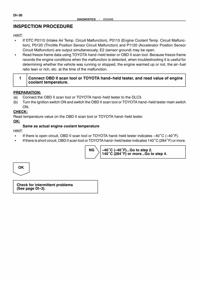
DI--30--DIAGNOSTICS ENGINE
INSPECTION PROCEDURE
HINT:S If DTC P0110 (Intake Air Temp. Circuit Malfunction), P0115 (Engine Coolant Temp. Circuit Malfunc-
tion), P0120 (Throttle Position Sensor Circuit Malfunction) and P1120 (Accelerator Position SensorCircuit Malfunction) are output simultaneously, E2 (sensor ground) may be open.
S Read freeze frame data using TOYOTA hand--held tester or OBD II scan tool. Because freeze framerecords the engine conditions when the malfunction is detected, when troubleshooting it is useful fordetermining whether the vehicle was running or stopped, the engine warmed up or not, the air--fuelratio lean or rich, etc. at the time of the malfunction.
1 Connect OBD II scan tool or TOYOTA hand--held tester, and read value of enginecoolant temperature.
PREPARATION:(a) Connect the OBD II scan tool or TOYOTA hand--held tester to the DLC3.(b) Turn the ignition switch ON and switch the OBD II scan tool or TOYOTA hand--held tester main switch
ON.CHECK:Read temperature value on the OBD II scan tool or TOYOTA hand--held tester.OK:
Same as actual engine coolant temperatureHINT:S If there is open circuit, OBD II scan tool or TOYOTA hand--held tester indicates --40˚C (--40˚F).S If there is short circuit, OBD II scan tool or TOYOTAhand--held tester indicates 140˚C (284˚F) ormore.
NG --40˚C (--40˚F)...Go to step 2.140˚C (284˚F) or more...Go to step 4.
OK
Check for intermittent problems(See page DI--3).

BE6653A00365
A00366
ON
Engine CoolantTemp. Sensor
ECM
2
1E2
E1
THW
5V14
18E13
E13
M02204
ON
Engine CoolantTemp. Sensor
ECM
2
1
E2
E1
THW
5V
14
18
E13
E13
E2THW
--DIAGNOSTICS ENGINEDI--31
2 Check for open in harness or ECM.
PREPARATION:(a) Disconnect the engine coolant temp. sensor connector.(b) Connect sensor wire harness terminals together.(c) Turn the ignition switch ON.CHECK:Read temperature value on the OBD II scan tool or TOYOTAhand--held tester.OK:
Temperature value: 140°C (284°F) or more
OK Confirm good connection at sensor. If OK,replace engine coolant temp. sensor.
NG
3 Check for open in harness or ECM.
PREPARATION:(a) Remove the wire harness boot.(b) Connect between terminals THWandE2 of the ECMcon-
nector.HINT:Engine coolant temp. sensor connector is disconnected.Before checking, do a visual and contact pressure check for theECM connector (See page IN--19).(c) Turn the ignition switch ON.CHECK:Read temperature value on the OBD II scan tool or TOYOTAhand--held tester.OK:
Temperature value: 140°C (284°F) or more
OK Open in harness between terminals E2 or THW,repair or replace harness.
NG
Confirm good connection at ECM.If OK, check and replace ECM.(See page IN--19)
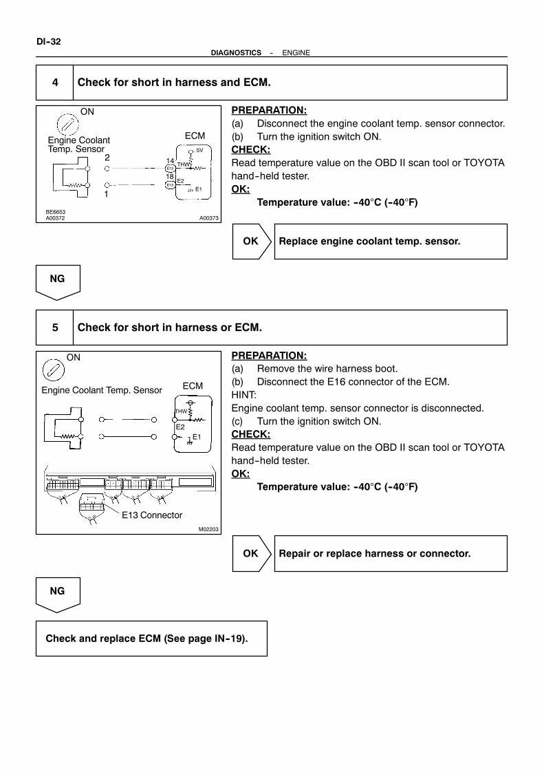
BE6653A00372 A00373
ON
Engine CoolantTemp. Sensor
2
1
5V
E1
ECM
E2
THW14
18E13
E13
M02203
Engine Coolant Temp. Sensor
ON
ECM
E1E2
THW
E13 Connector
DI--32--DIAGNOSTICS ENGINE
4 Check for short in harness and ECM.
PREPARATION:(a) Disconnect the engine coolant temp. sensor connector.(b) Turn the ignition switch ON.CHECK:Read temperature value on the OBD II scan tool or TOYOTAhand--held tester.OK:
Temperature value: --40°C (--40°F)
OK Replace engine coolant temp. sensor.
NG
5 Check for short in harness or ECM.
PREPARATION:(a) Remove the wire harness boot.(b) Disconnect the E16 connector of the ECM.HINT:Engine coolant temp. sensor connector is disconnected.(c) Turn the ignition switch ON.CHECK:Read temperature value on the OBD II scan tool or TOYOTAhand--held tester.OK:
Temperature value: --40°C (--40°F)
OK Repair or replace harness or connector.
NG
Check and replace ECM (See page IN--19).

A02396A02395 A02624
Throttle
Position
Sensor
OutputVoltage
(V)
0
1.5
ThrottleValveOpeningAngle (deg)
70 125
VTA
VTA25
VTA2 VTAE2 VC
Movable Range
Usable Range
Usable Range*1 *2
*1
*2
Movable Range
UsableRange
*2
*1
*1: Accelerator pedalreleased (15˚)
*2: Accelerator pedaldepressed
(about 100˚)
VTA2 line openor grandshort
Throttle valve opening position expressed as percentage and voltage
Accelerator pedal released Accelerator pedal depressed
THROTTLEPOS THROTTLEPOS#2 THROTTLEPOS THROTTLEPOS#2
0 %
0 %
100 %
8∼ 20%
0V
2.0∼ 2.9V
0V
5V
0 %
0 %
100 %
0V
4.6∼ 5.1V
0V
5V
Trouble area
VC line open
VTA line open or grand short
E2 line open
64 ∼ 96%
--DIAGNOSTICS ENGINEDI--33
DTC P0120 Throttle Position SensorCircuit Malfunction
CIRCUIT DESCRIPTION
Throttle position sensor is mounted on the throttle body and it have the 2 sensors to detect the throttle open-ing angle and the malfunction of the throttle position sensor’s own.The voltage applied to the terminals VTA and VTA2 of the ECM changes between 0 V and 5 V in proportionto the opening angle of the throttle valve.The ECM judges the current opening angle of the throttle valve from these signals input from terminals VTAand VTA2, and the ECM controls the throttle motor to make the throttle valve angle properly in response todriving condition.If this DTC is stored, the ECM shuts down the power for the throttle motor and the electromagnetic clutch,and the throttle valve is fully closed by the return spring.However, the opening angle of the throttle valve can be controlled by the throttle lever through the throttlecable.
DTC No. DTC Detecting Condition Trouble Area
P0120
Condition (a), (b), (c), (d) or (e) continues for 2.0 seconds:
(a) VTA≦ 0.2 V
(b) VTA2≦ 0.5 V
(c) VTA≧ 4.8 V
(d) When VTA≧ 0.2 V and≦ 2.0 V, and VTA2≧ 4.97 V
(b) VTA--VTA2≦ 0.02 V
SOpen or short in throttle position sensor circuit
SThrottle position sensor
SECM
Condition (a) continues for 0.4 seconds:
(a) VTA≦ 0.2 V and VTA2≦ 0.5 V
HINT:After confirming DTC P0120 use the OBD II scan tool or TOYOTA hand--held tester to confirm the throttlevalve opening percentage.
DI2OM--01

M01969
Throttle Position Sensor ECM
2
1
3
4
Y
L
Y--B
BR
13
2
20
18
VTA
VC
VTA2
E2
E13
E13
E13
E13
DI--34--DIAGNOSTICS ENGINE
WIRING DIAGRAM
INSPECTION PROCEDURE
HINT:S If DTC P0110 (Intake Air Temp. Circuit Malfunction), P0115 (Engine Coolant Temp. Circuit Malfunc-
tion), P0120 (Throttle Position Sensor Circuit Malfunction) and P1120 (Accelerator Pedal PositionSensor Circuit Malfunction) are output simultaneously, E2 (Sensor Ground) may be open.
S Read freeze frame data using TOYOTA hand--held tester or OBD II scan tool. Because freeze framerecords the engine conditions when the malfunction is detected, when troubleshooting it is useful fordetermining whether the vehicle was running or stopped, the engine warmed up or not, the air--fuelratio lean or rich, etc. at the time of the malfunction.
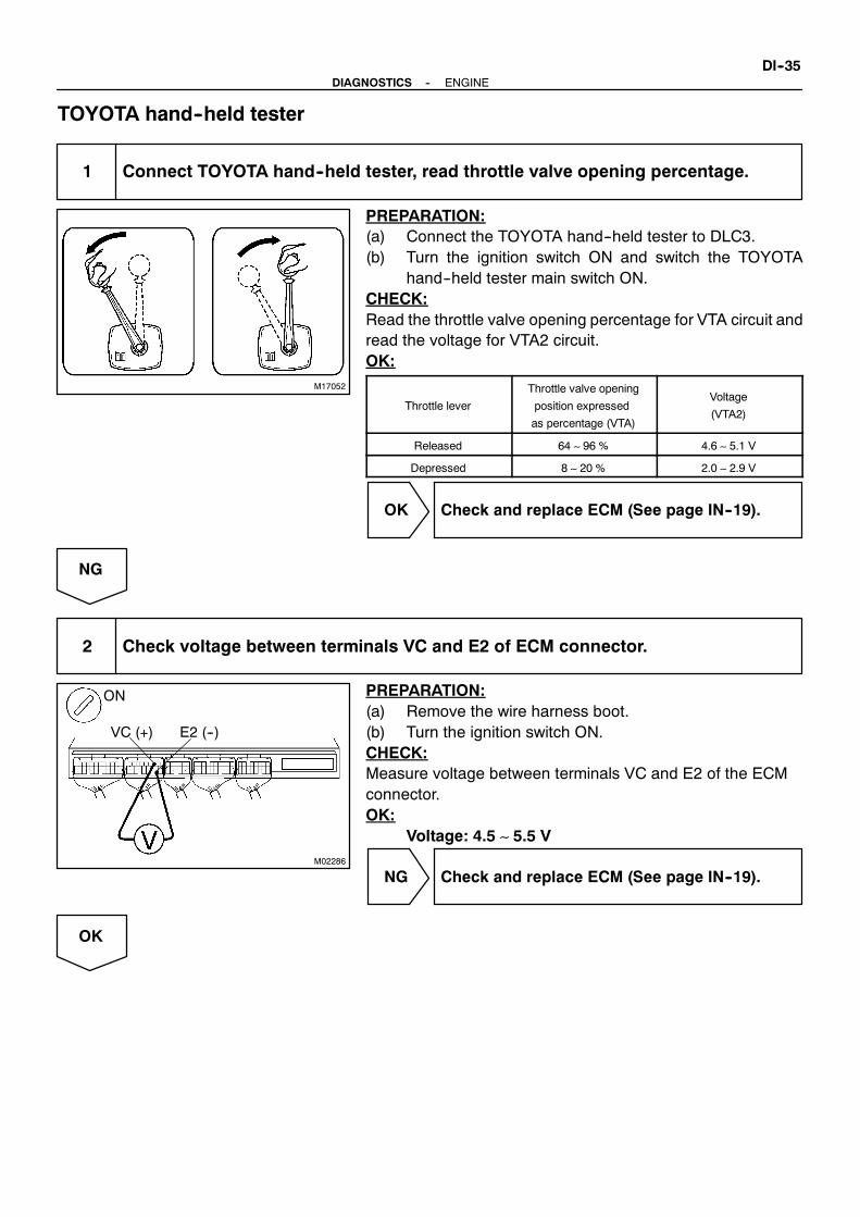
M17052
M02286
E2 (--)VC (+)
ON
--DIAGNOSTICS ENGINEDI--35
TOYOTA hand--held tester
1 Connect TOYOTA hand--held tester, read throttle valve opening percentage.
PREPARATION:(a) Connect the TOYOTA hand--held tester to DLC3.(b) Turn the ignition switch ON and switch the TOYOTA
hand--held tester main switch ON.CHECK:Read the throttle valve opening percentage for VTA circuit andread the voltage for VTA2 circuit.OK:
Throttle lever
Throttle valve opening
position expressed
as percentage (VTA)
Voltage
(VTA2)
Released 64 ∼ 96 % 4.6 ∼ 5.1 V
Depressed 8 ∼ 20 % 2.0 ∼ 2.9 V
OK Check and replace ECM (See page IN--19).
NG
2 Check voltage between terminals VC and E2 of ECM connector.
PREPARATION:(a) Remove the wire harness boot.(b) Turn the ignition switch ON.CHECK:Measure voltage between terminals VC and E2 of the ECMconnector.OK:
Voltage: 4.5 ∼ 5.5 V
NG Check and replace ECM (See page IN--19).
OK

M02285
ONVTA (+) E2 (--)
VTA2 (+)
DI--36--DIAGNOSTICS ENGINE
3 Check voltage between terminals VTA, VTA2 and E2 of ECM connector.
PREPARATION:(a) Remove the wire harness boot.(b) Turn the ignition switch ON.CHECK:Measure voltage between terminals VTA, VTA2 and E2 of theECM connector.OK:
A l t d lVoltage
Accelerator pedalVTA VTA2
Released 0.4 ∼ 1.0 V 2.0 ∼ 2.9 V
Depressed 3.2 ∼ 4.8 V 4.6 ∼ 5.1 V
OK Check and replace ECM (See page IN--19).
NG
4 Check throttle position sensor (See page SF--31).
NG Replace throttle position sensor(See page SF--37).
OK
Check for open and short in harness and connector between ECM and throttle position sensor(VC, VTA, VTA2, E2 line) (See page IN--19).

M02286
E2 (--)VC (+)
ON
M02285
ONVTA (+) E2 (--)
VTA2 (+)
--DIAGNOSTICS ENGINEDI--37
OBD II scan tool (excluding TOYOTA hand--held tester)
1 Check voltage between terminals VC and E2 of ECM connector.
PREPARATION:(a) Remove the wire harness boot.(b) Turn the ignition switch ON.CHECK:Measure voltage between terminals VC and E2 of the ECMconnector.OK:
Voltage: 4.5 ∼ 5.5 V
NG Check and replace ECM (See page IN--19).
OK
2 Check voltage between terminals VTA, VTA2 and E2 of ECM connector.
PREPARATION:(a) Remove the wire harness boot.(b) Turn the ignition switch ON.CHECK:Measure voltage between terminals VTA, VTA2 and E2 of theECM connector.OK:
A l t d lVoltage
Accelerator pedalVTA VTA2
Released 0.4 ∼ 1.0 V 2.0 ∼ 2.9 V
Depressed 3.2 ∼ 4.8 V 4.6 ∼ 5.1 V
OK Check and replace ECM (See page IN--19).
NG

DI--38--DIAGNOSTICS ENGINE
3 Check throttle position sensor (See page SF--31).
NG Replace throttle position sensor(See page SF--37).
OK
Check for open and short in harness and connector between ECM and throttle position sensor(VC, VTA, VTA2, E2 line) (See page IN--19).

--DIAGNOSTICS ENGINEDI--39
DTC P0121 Throttle Position SensorCircuit Range/Performance Problem
CIRCUIT DESCRIPTION
Refer to DTC P0120 (Throttle Position Sensor CIrcuit Malfunction) on page DI---33.
DTC No. DTC Detecting Condition Trouble Area
P0121Condition (a) continue for 2.0 seconds:
(a) Difference between VTA and VTA2 is out of threshold
SThrottle position sensor
SECM
INSPECTION PROCEDURE
HINT:Read freeze frame data using TOYOTAhand--held tester or OBD II scan tool. Because freeze frame recordsthe engine conditions when the malfunction is detected, when troubleshooting it is useful for determiningwhether the engine was running or stopped, the engine warmed up or not, the air--fuel ratio lean or rich, etc.at the time of the malfunction.
Replace throttle position sensor (See page SF--37).
DI2ON--01

P21894
ECM
KNKL
E1
E1
18
E14
GR
BED1
2
Knock Sensor 2(on Right Bank)
ED1
31
Knock Sensor 1(on Left Bank)
1
17KNKRE14
B
GR
DI--40--DIAGNOSTICS ENGINE
DTC P0325 Knock Sensor 1 Circuit Malfunction
DTC P0330 Knock Sensor 2 Circuit Malfunction
CIRCUIT DESCRIPTION
Knock sensors are fitted one to the right bank and left bank of the cylinder block to detect engine knocking.This sensor contains a piezoelectric element which generates a voltage when it becomes deformed, whichoccurswhen the cylinderblock vibratesdue to knocking. If engine knocking occurs, ignition timing is retardedto suppress it.
DTC No. DTC Detecting Condition Trouble Area
P0325No knock sensor 1 signal to ECM with engine speed between
1,700 rpm and 5,400 rpm
SOpen or short in knock sensor 1 circuit
SKnock sensor 1 (looseness)
SECM
P0330No knock sensor 2 signal to ECM with engine speed between
1,700 rpm and 5,400 rpm
SOpen or short in knock sensor 2 circuit
SKnock sensor 2 (looseness)
SECM
WIRING DIAGRAM
DI2OU--01
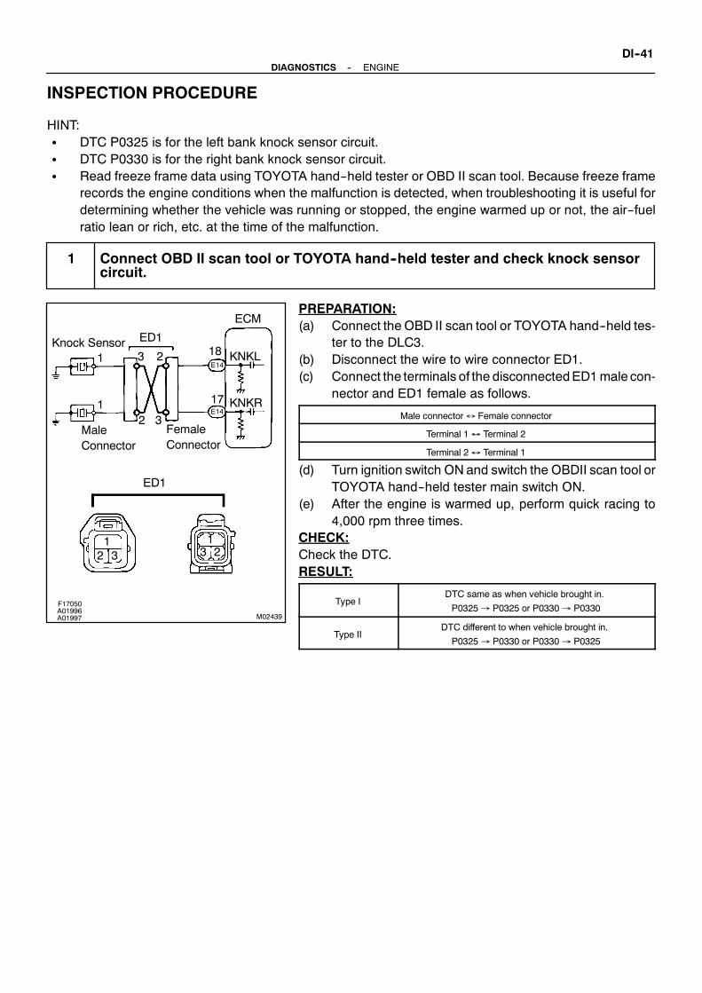
M02439
ECM
KNKL
KNKR
3 2
2 3FemaleConnector
MaleConnector
Knock Sensor1
1
ED1
ED1
E14
17
18
321
3 21
E14
F17050A01996A01997
--DIAGNOSTICS ENGINEDI--41
INSPECTION PROCEDURE
HINT:S DTC P0325 is for the left bank knock sensor circuit.S DTC P0330 is for the right bank knock sensor circuit.S Read freeze frame data using TOYOTA hand--held tester or OBD II scan tool. Because freeze frame
records the engine conditions when the malfunction is detected, when troubleshooting it is useful fordetermining whether the vehicle was running or stopped, the engine warmed up or not, the air--fuelratio lean or rich, etc. at the time of the malfunction.
1 Connect OBD II scan tool or TOYOTA hand--held tester and check knock sensorcircuit.
PREPARATION:(a) Connect the OBD II scan tool or TOYOTA hand--held tes-
ter to the DLC3.(b) Disconnect the wire to wire connector ED1.(c) Connect the terminals of the disconnectedED1male con-
nector and ED1 female as follows.
Male connector↔ Female connector
Terminal 1↔ Terminal 2
Terminal 2↔ Terminal 1
(d) Turn ignition switch ON and switch the OBDII scan tool orTOYOTA hand--held tester main switch ON.
(e) After the engine is warmed up, perform quick racing to4,000 rpm three times.
CHECK:Check the DTC.RESULT:
Type IDTC same as when vehicle brought in.
P0325→ P0325 or P0330→ P0330
Type IIDTC different to when vehicle brought in.
P0325→ P0330 or P0330→ P0325

FI6510FI6511 A00068
KNK signal waveform0.5VDivision
0.5V/Division
0V
0V
5 m sec./Division
0.2 m sec./Division
DI--42--DIAGNOSTICS ENGINE
Reference: INSPECTION USING OSCILLOSCOPES With the engine racing (4,000 rpm)measure between ter-
minal KNK1, KNK2 of the ECM connector and bodyground.
HINT:The correct waveforms are as shown.
S Spread the time on the horizontal axis, and confirm thatperiod of the wave is 0.13 m sec.(Normal mode vibration frequency of knock sensor:7.7 kHz)
HINT:If normal mode vibration frequency is not 7.7 kHz, the sensoris malfunctioning.
Type II Go to step 3.
Type I
2 Check for open and short in harness and connector between ED1 connector andECM (See page IN--19).
NG Repair or replace harness or connector.
OK
Check and replace ECM (See page IN--19).

--DIAGNOSTICS ENGINEDI--43
3 Check for open and short in harness and connector between ED1 connector andknock sensor (See page IN--19).
HINT:S If DTC P0325 has changed to P0330, check the knock sensor circuit on the left bank side.S If DTC P0330 has changed to P0325, check the knock sensor circuit on the right bank side.
NG Repair or replace harness or connector.
OK
Replace knock sensor.
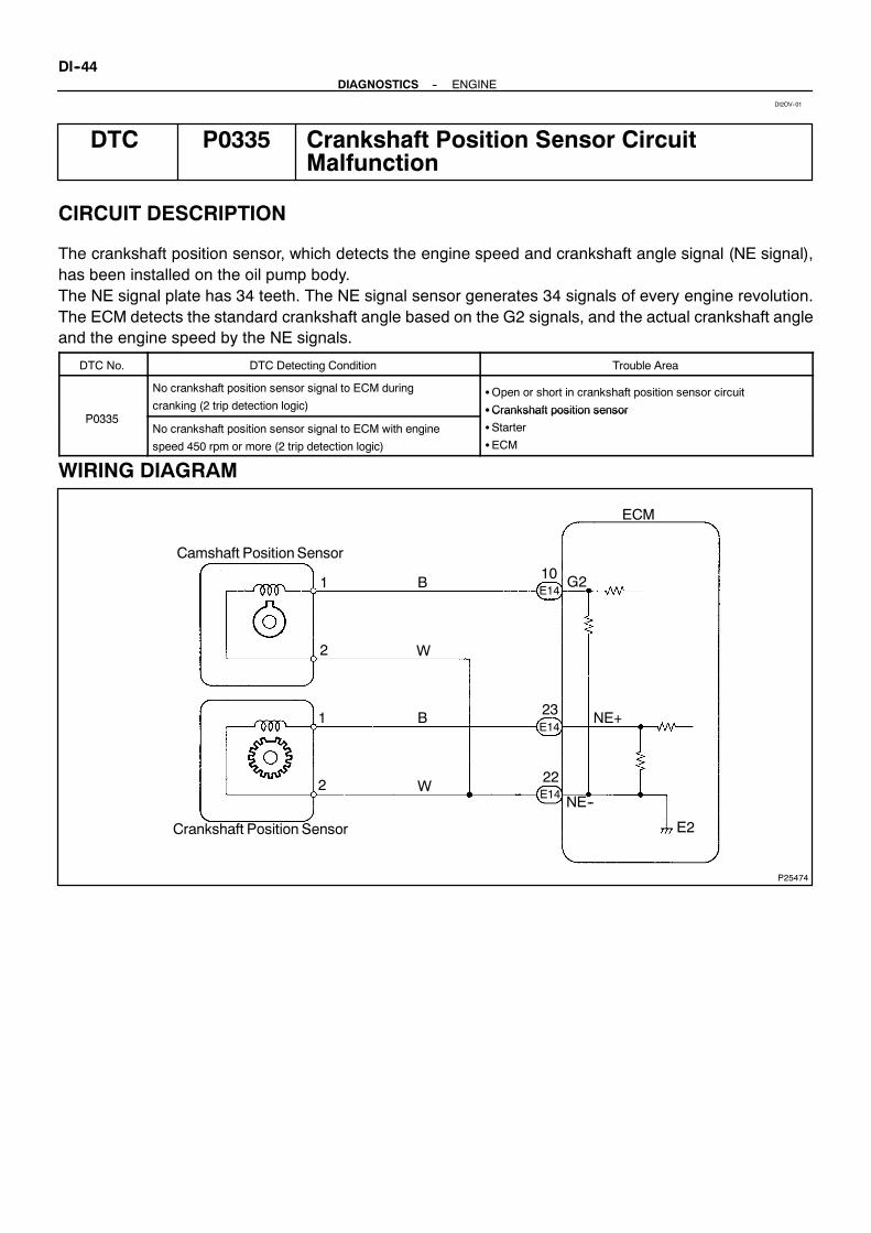
P25474
Camshaft PositionSensor
Crankshaft Position Sensor
W
ECM
G2
NE+
NE--
E2
10
2
1
2
1
23
22
E14
E14
E14
B
B
W
DI--44--DIAGNOSTICS ENGINE
DTC P0335 Crankshaft Position Sensor CircuitMalfunction
CIRCUIT DESCRIPTION
The crankshaft position sensor, which detects the engine speed and crankshaft angle signal (NE signal),has been installed on the oil pump body.The NE signal plate has 34 teeth. The NE signal sensor generates 34 signals of every engine revolution.The ECM detects the standard crankshaft angle based on the G2 signals, and the actual crankshaft angleand the engine speed by the NE signals.
DTC No. DTC Detecting Condition Trouble Area
P0335
No crankshaft position sensor signal to ECM during
cranking (2 trip detection logic)SOpen or short in crankshaft position sensor circuit
SCrankshaft position sensorP0335
No crankshaft position sensor signal to ECM with engine
speed 450 rpm or more (2 trip detection logic)
SCrankshaft position sensor
SStarter
SECM
WIRING DIAGRAM
DI2OV--01

FI7059FI7060 A00069
G2, NE signalwaveform
G2
NE
NE
5V/Division
5V/Division
20 m sec./Division (Idling)
10 m sec./Division (Idling)
G2
--DIAGNOSTICS ENGINEDI--45
INSPECTION PROCEDURE
HINT:S Perform troubleshooting of DTCP0335 first. If no trouble is found, troubleshoot the followingmechani-
cal systems.S Read freeze frame data using TOYOTA hand--held tester or OBD II scan tool. Because freeze frame
records the engine conditions when the malfunction is detected, when troubleshooting it is useful fordetermining whether the vehicle was running or stopped, the engine warmed up or not, the air--fuelratio lean or rich, etc. at the time of the malfunction.
1 Check resistance of crankshaft position sensor (See page IG--1).
Reference: INSPECTION USING OSCILLOSCOPEDuring cranking or idling, check between terminals G2 andNE--, NE and NE-- of the ECM connector.HINT:The correct waveforms are as shown.
NG Replace crankshaft position sensor.
OK
2 Check for open and short in harness and connector between ECM andcrankshaft position sensor (See page IN--19).
NG Repair or replace harness or connector.
OK

DI--46--DIAGNOSTICS ENGINE
3 Inspect sensor installation and teeth of signal plate.
NG Tighten sensor. Replace signal plate.
OK
Check and replace ECM (See page IN--19).

--DIAGNOSTICS ENGINEDI--47
DTC P0340 Camshaft Position Sensor CircuitMalfunction
CIRCUIT DESCRIPTION
Camshaft position sensor (G2 signal) consist of a signal plate and pickup coil.The G2 signal plate has 1 tooth, on its outer circumference and is mounted on the left bank camshafts.When the camshafts rotate, the protrusion on the signal plate and the air gap on the pickup coil change,causing fluctuations in the magnetic field and generating an electromotive force in the pickup coil.The NE signal plate has 34 teeth and is mounted on the crankshaft. The NE signal sensor generates 34signals for every engine revolution. The ECM detects the standard crankshaft angle based on the G2 signaland the actual crankshaft angle and the engine speed by the NE signals.
DTC No. DTC Detecting Condition Trouble Area
P0340
No camshaft position sensor signal to ECM during cranking
(2 trip detection logic)SOpen or short in camshaft position sensor circuit
SCamshaft position sensorP0340
No camshaft position sensor signal to ECM with engine
speed 600 rpm or more
SCamshaft position sensor
SStarter
SECM
WIRING DIAGRAM
Refer to DTC P0335 (Crankshaft Positio Sensor Circuit Malfunction) on page DI--44 for theWIRING DIAGRAM.
INSPECTION PROCEDURE
HINT:Read freeze frame data using TOYOTAhand--held tester or OBD II scan tool. Because freeze frame recordsthe engine conditions when the malfunction is detected, when troubleshooting it is useful for determiningwhether the engine was running or stopped, the engine warmed up or not, the air--fuel ratio lean or rich, etc.at the time of the malfunction.
1 Check resistance of camshaft position sensor (See page IG--1).
Reference: INSPECTION USING OSCILLOSCOPERefer to DTC P0335 (Crankshaft Position Sensor ”A” Circuit Malfunction) on page DI--44 for theReference: INSPECTION USING OSCILLOSCOPE.
NG Replace camshaft position sensor.
OK
DI2OW--01

DI--48--DIAGNOSTICS ENGINE
2 Check for open and short in harness and connector between ECM and camshaftposition sensor (See page IN--19).
NG Repair or replace harness or connector.
OK
3 Inspect sensor installation.
NG Tighten sensor.
OK
Check and replace ECM (See page IN--19).

A02396A02395 A02624
0
1.5
Throttle lever Opening Angle (deg)
70 125
VPA
VPA25
Movable Range
Usable Range
Usable Range*1 *2
*1
*2
Movable Range
UsableRange
*2
*1
*1: Throttle leverreleased (15˚)
*2: Throttle leverdepressed
(about 100˚)
AcceleratorPedal
Position
Sensor
OutputVoltage
(V)
VPA2 VPAE2 VC
VPA2 lineopenor grandshort
Accelerator pedal opening position expressed as voltage
Throttle lever released Throttle lever depressed
ACCEL POS #1
0V
0V
0V
1.8∼ 2.7V
0V
5V
0V
4.7∼ 5.1V
0V
5V
Trouble area
VC line open
VPA line open or grandshort
E2 line open
ACCEL POS #2 ACCEL POS #1 ACCEL POS #2
0.3∼ 0.9V
5V
0V
0V
3.2∼ 4.8V
5V
--DIAGNOSTICS ENGINEDI--49
DTC P1120 Accelerator Position Sensor CircuitMalfunction
CIRCUIT DESCRIPTION
Accelerator pedal position sensor is mounted on the throttle body and it have the 2 sensors to detects theaccelerator position and a malfunction of the accelerator position’s own.The accelerator pedal position sensor is connected with the throttle lever by the throttle wire and the voltageapplied to the terminals VPAandVPA2of theECMchangesbetween 0V and5V in proportion to the openingangle of the throttle lever.The ECM judges the current opening angle of the throttle lever from these signals input from terminals VPAand VPA2 and the ECM controls the throttle motor based on these signals.If this DTC is stored, the ECM shuts down the power for the throttle motor and the magnetic clutch, and thethrottle valve is fully closed by the return spring.However, the opening angle of the throttle valve can be controlled by the throttle lever through the throttlecable.
DTC No. DTC Detecting Condition Trouble Area
P1120
Condition (a), (b), (c) or (d) continues for 2.0 seconds:
(a) VPA≦ 0.2 V
(b) VPA2≦ 0.5 V
(c) VPA≧ 4.8 V
(d) When VPA≧ 0.2 V and≦ 1.8 V, and VPA2≧ 4.97 V
SOpen or short in accelerator pedal position sensor circuit
SAccelerator pedal position sensor
ECMCondition (a) or (b) continues for 0.4 seconds:
(a) VPA≦ 0.2 V and VPA2≦ 1.5 V
(b) VPA--VPA2≦ 0.02 V
SECM
HINT:After confirmingDTCP1120 use theOBD II scan tool orTOYOTAhand--held tester to confirm theacceleratorpedal opening percentage.
DI2P3--01

M01969
ECMAccelerator Pedal Position Sensor
VC
VPAR
L
21
BR
2
2
3
1
18E13
4
R--BE13
E13
E13
9
E2
VPA2
M17052
DI--50--DIAGNOSTICS ENGINE
WIRING DIAGRAM
INSPECTION PROCEDURE
HINT:S If DTC P0110 (Intake Air Temp. Circuit Malfunction), P0115 (Engine Coolant Temp. Circuit Malfunc-
tion), P0120 (Throttle Position Sensor Circuit Malfunction) and P1120 (Accelerator Pedal PositionSensor Circuit Malfunction) are output simultaneously, E2 (Sensor Ground) may be open.
S Read freeze frame data using TOYOTA hand--held tester or OBD II scan tool. Because freeze framerecords the engine conditions when the malfunction is detected, when troubleshooting it is useful fordetermining whether the engine was running or stopped, the engine warmed up or not, the air--fuelratio lean or rich, etc. at the time of the malfunction.
TOYOTA hand--held tester
1 Connect TOYOTA hand--held tester, read the voltage for accelerator pedal posi-tion sensor data.
PREPARATION:(a) Connect the TOYOTA hand--held tester to DLC3.(b) Turn the ignition switch ON and switch the TOYOTA
hand--held tester main switch ON.CHECK:Read the voltage for the throttle lever position sensor data.OK:
Throttle lever VPA VPA2
Releaded 0.3 ∼ 0.9 V 1.8 ∼ 2.7 V
Depressed 3.2 ∼ 4.8 V 4.7 ∼ 5.1 V
OK Check and replace ECM (See page IN--19).
NG

M02286
E2 (--)VC (+)
ON
M02440
ON
VPA (+) VPA2 (+)
E2 (--)
--DIAGNOSTICS ENGINEDI--51
2 Check voltage between terminals VC and E2 of ECM connector.
PREPARATION:(a) Remove the wire harness boot.(b) Turn the ignition switch ON.CHECK:Measure voltage between terminals VC and E2 of the ECMconnector.OK:
Voltage: 4.5 ∼ 5.5 V
NG Check and replace ECM (See page IN--19).
OK
3 Check voltage between terminals VPA, VPA2 and E2 of ECM connector.
PREPARATION:(a) Remove the wire harness boot.(b) Turn the ignition switch ON.CHECK:Measure voltage between terminals VPA, VPA2 and E2 of theECM connector.OK:
Th ttl lVoltage
Throttle leverVPA VPA2
Released 0.3 ∼ 0.9 V 1.8 ∼ 2.7 V
Depressed 3.2 ∼ 4.8 V 4.7 ∼ 5.1 V
OK Check and replace ECM (See page IN--19).
NG

M02286
E2 (--)VC (+)
ON
DI--52--DIAGNOSTICS ENGINE
4 Check accelerator pedal position sensor (See page SF--31).
NG Replace accelerator pedal position sensor(See page SF--42).
OK
Check for open andshort in harness andconnector betweenECMandaccelerator pedal positionsensor (VC, VPA,VPA2, E2 line) (See page IN--19).
OBD II scan tool (excluding TOYOTA hand--held tester)
1 Check voltage between terminals VC and E2 of ECM connector.
PREPARATION:(a) Remove the wire harness boot.(b) Turn the ignition switch ON.CHECK:Measure voltage between terminals VC and E2 of the ECMconnector.OK:
Voltage: 4.5 ∼ 5.5 V
NG Check and replace ECM (See page IN--19).
OK

--DIAGNOSTICS ENGINEDI--53
2 Check voltage between terminals VPA, VPA2 and E2 of ECM connector.
PREPARATION:(a) Remove the wire harness boot.(b) Turn the ignition switch ON.CHECK:Measure voltage between terminals VPA, VPA2 and E2 of theECM connector.OK:
Th ttl lVoltage
Throttle leverVPA VPA2
Relesed 0.3 ∼ 0.9 V 1.8 ∼ 2.7 V
Depressed 3.2 ∼ 4.8 V 4.7 ∼ 5.1 V
OK Check and replace ECM (See page IN--19).
NG
3 Check accelerator pedal position sensor (See page SF--31).
NG Replace accelerator pedal position sensor(See page SF--37).
OK
Check for open andshort in harness andconnector betweenECMandaccelerator pedal positionsensor (VC, VPA,VPA2, E2 line) (See page IN--19).

DI--54--DIAGNOSTICS ENGINE
DTC P1121 Accelerator Pedal Position Sensor Range/Performance Problem
CIRCUIT DESCRIPTION
Refer to DTC P1120 (Accelerator Pedal Position Sensor Circuit Malfunction) on page DI--49.
DTC No. DTC Detecting Condition Trouble Area
P1121Condition (a) continue for 2.0 seconds:
(a) Difference between VPA and VPA2 is out of threshold
SAccelerator Pedal position sensor
SECM
WIRING DIAGRAM
Refer to DTC P1120 (Accelerator Pedal Position Sensor Circuit Malfunction) on page DI--49.
INSPECTION PROCEDURE
HINT:Read freeze frame data using TOYOTAhand--held tester or OBD II scan tool. Because freeze frame recordsthe engine conditions when the malfunction is detected, when troubleshooting it is useful for determiningwhether the engine was running or stopped, the engine warmed up or not, the air--fuel ratio lean or rich, etc.at the time of the malfunction.
Replace accelerator pedal position sensor (See page SF--37).
DI2P4--01

A02990
ThrottleControlMotor2
1
3
4
R
G
G--W
B--R
ECM
8
7
12
8
M+
M--
CL+
CL--
E14
E12
E13
E14
--DIAGNOSTICS ENGINEDI--55
DTC P1125 Throttle Control Motor Circuit Malfunction
CIRCUIT DESCRIPTION
Throttle motor is operated by the ECM and it opens and closes the throttle valve.The opening angle of the throttle valve is detected by the throttle position sensor which is mounted on thethrottle body and it provides feedback to the ECM to control the throttle motor in order to the throttle valveopening angle properly in response to driving condition.If this DTC is stored, the ECM shuts down the power for the throttle motor and the magnetic clutch, and thethrottle valve is fully closed by the return spring.However, the opening angle of the throttle valve can be controlled by the throttle lever through the throttlecable.
DTC No. DTC Detecting Condition Trouble Area
Condition (a) and (b) continues for 0.8 seconds:
(a) Throttle control motor output duty≧ 80 %
(b) Throttle control motor current < 0.3 A SOpen or short in throttle control motor circuit
P1125Throttle control motor current≧ 16 A
SThrottle control motor
SECMUnder condition continue for 0.6 seconds:
Throttle control motor current≧ 7 A
SECM
WIRING DIAGRAM
DI2P5--01

A03403A03404 A03675
M+ Signal Waveform
5V/
Division
GND
1msec./Division
M-- Signal Waveform
GND
5V/
Division
1msec./Division
DI--56--DIAGNOSTICS ENGINE
INSPECTION PROCEDURE
HINT:Read freeze frame data using TOYOTAhand--held tester or OBD II scan tool. Because freeze frame recordsthe engine conditions when the malfunction is detected, when troubleshooting it is useful for determiningwhether the engine was running or stopped, the engine warmed up or not, the air--fuel ratio lean or rich, etc.at the time of the malfunction.
1 Check throttle control motor circuit.
When using TOYOTA hand--held tester:PREPARATION:(a) Connect the TOYOTA hand--held tester to the DLC3.(b) Turn the ignition switchON and TOYOTA hand--held test-
er main switch ON.CHECK:Read the throttle motor current value on the TOYOTA hand--held tester.OK:
Blow 7 A at idleWhen not using TOYOTA hand--held tester:PREPARATION:(a) Connect the oscilloscope between terminals M+ or M--
and E1 of the ECM.(b) Start the engine.CHECK:Check thewaveformbetween terminalsM+ orM-- and E1 of theECM when engine is idling.OK:
The correct waveforms are as shown.HINT:The waveform frequency varies depending on the throttleopening.
OK Check and replace ECM (See page IN--19).
NG

A02004 A02394 A02625
21
--DIAGNOSTICS ENGINEDI--57
2 Check throttle control motor.
PREPARATION:Disconnect the throttle control motor and magnetic clutch con-nector.CHECK:Measure resistance between terminals 1 and 2 of the throttlecontrol motor and magnetic clutch.OK:
Resistance: 0.3 ∼ 100 Ω at 20˚C (68˚F)
NG Replace throttle control motor(See page SF--37).
OK
3 Check for open and short in harness and connector between throttle controlmotor and ECM (See page IN--19).
NG Repair or replace.
OK
Check and replace ECM (See page IN--19).
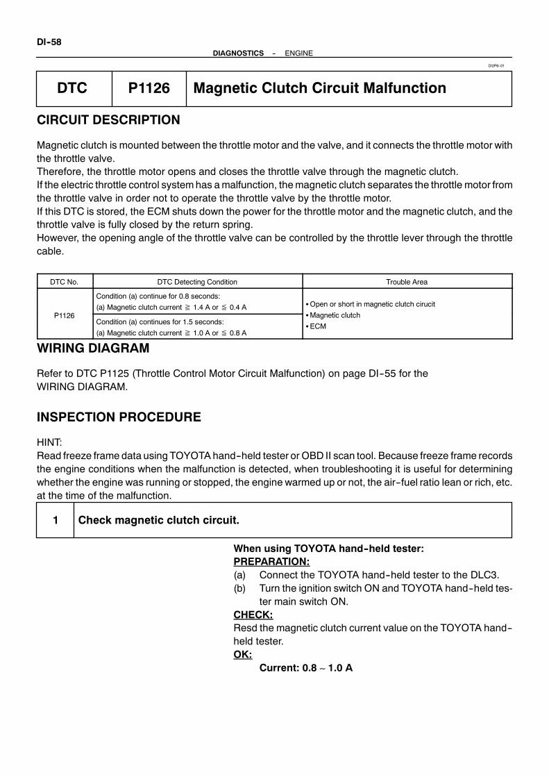
DI--58--DIAGNOSTICS ENGINE
DTC P1126 Magnetic Clutch Circuit Malfunction
CIRCUIT DESCRIPTION
Magnetic clutch is mounted between the throttle motor and the valve, and it connects the throttle motor withthe throttle valve.Therefore, the throttle motor opens and closes the throttle valve through the magnetic clutch.If the electric throttle control systemhas amalfunction, themagnetic clutch separates the throttle motor fromthe throttle valve in order not to operate the throttle valve by the throttle motor.If this DTC is stored, the ECM shuts down the power for the throttle motor and the magnetic clutch, and thethrottle valve is fully closed by the return spring.However, the opening angle of the throttle valve can be controlled by the throttle lever through the throttlecable.
DTC No. DTC Detecting Condition Trouble Area
P1126
Condition (a) continue for 0.8 seconds:
(a) Magnetic clutch current≧ 1.4 A or≦ 0.4 A SOpen or short in magnetic clutch cirucit
M ti l t hP1126Condition (a) continues for 1.5 seconds:
(a) Magnetic clutch current≧ 1.0 A or≦ 0.8 A
SMagnetic clutch
SECM
WIRING DIAGRAM
Refer to DTC P1125 (Throttle Control Motor Circuit Malfunction) on page DI--55 for theWIRING DIAGRAM.
INSPECTION PROCEDURE
HINT:Read freeze frame data using TOYOTAhand--held tester or OBD II scan tool. Because freeze frame recordsthe engine conditions when the malfunction is detected, when troubleshooting it is useful for determiningwhether the engine was running or stopped, the engine warmed up or not, the air--fuel ratio lean or rich, etc.at the time of the malfunction.
1 Check magnetic clutch circuit.
When using TOYOTA hand--held tester:PREPARATION:(a) Connect the TOYOTA hand--held tester to the DLC3.(b) Turn the ignition switch ON and TOYOTA hand--held tes-
ter main switch ON.CHECK:Resd the magnetic clutch current value on the TOYOTA hand--held tester.OK:
Current: 0.8 ∼ 1.0 A
DI2P6--01
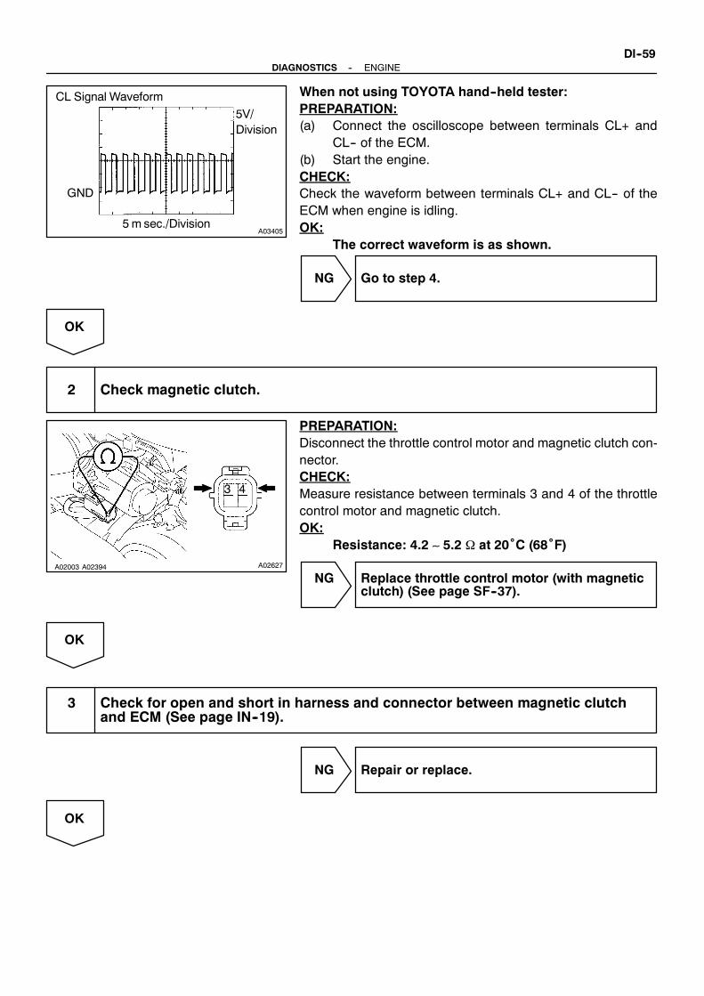
A03405
CL Signal Waveform
5V/Division
GND
5m sec./Division
A02003 A02394 A02627
43
--DIAGNOSTICS ENGINEDI--59
When not using TOYOTA hand--held tester:PREPARATION:(a) Connect the oscilloscope between terminals CL+ and
CL-- of the ECM.(b) Start the engine.CHECK:Check the waveform between terminals CL+ and CL-- of theECM when engine is idling.OK:
The correct waveform is as shown.
NG Go to step 4.
OK
2 Check magnetic clutch.
PREPARATION:Disconnect the throttle control motor and magnetic clutch con-nector.CHECK:Measure resistance between terminals 3 and 4 of the throttlecontrol motor and magnetic clutch.OK:
Resistance: 4.2 ∼ 5.2 Ω at 20˚C (68˚F)
NG Replace throttle control motor (with magneticclutch) (See page SF--37).
OK
3 Check for open and short in harness and connector between magnetic clutchand ECM (See page IN--19).
NG Repair or replace.
OK

DI--60--DIAGNOSTICS ENGINE
4 Check operation of magnetic clutch.
CHECK:(a) Clear the DTC.(b) Perform the following steps and check the DTC.
(1) Turn the ignition switch ON.(2) Start the engine.(3) Turn the ignition switch OFF and wait 3 seconds.(4) Turn the ignition switch ON.
OK:DTC P1126 is not stored
NG Replace throttle control motor (with magneticclutch) (See page SF--37).
OK
Check and replace ECM (See page IN--19).

M00923
CircuitBreaker120A
ECM
Battery
E15
7+BMLB--R EFI
B--R
ALT
--DIAGNOSTICS ENGINEDI--61
DTC P1127 EFI Actuator Power Source CircuitMalfunction
CIRCUIT DESCRIPTION
Battery positive voltage is supplied to terminal +BM of the ECM even once when the ignition switch is OFFfor the electric throttle control system.If this DTC is stored, the ECM shuts down the power for the throttle motor and the magnetic clutch, and thethrottle valve is fully closed by the return spring.However, the opening angle of the throttle valve can be controlled by the throttle lever through the throttlecable.
DTC No. DTC Detecting Condition Trouble Area
P1127 Open in EFI power source circuitSOpen in EFI power source circuit
SECM
WIRING DIAGRAM
DI2P7--01

M03975
Fuse Block
EFI Fuse
M01999
+BM (+)
DI--62--DIAGNOSTICS ENGINE
INSPECTION PROCEDURE
HINT:Read freeze frame data using TOYOTAhand--held tester or OBD II scan tool. Because freeze frame recordsthe engine conditions when the malfunction is detected, when troubleshooting it is useful for determiningwhether the engine was running or stopped, the engine warmed up or not, the air--fuel ratio lean or rich, etc.at the time of the malfunction.
1 Check EFI fuse.
PREPARATION:Remove the EFI fuse from fuse block.CHECK:Check countinuity of the EFI fuse.OK:
Continuity
NG Check for short in all harness and componentsconnected to EFI fuse.
OK
2 Check voltage between terminal +BM of ECM connector and body ground.
PREPARATION:Remove the wire harness boot.CHECK:Measure voltage between terminal +BM of the ECM connectorand body ground.OK:
Voltage: 9 ∼ 14 V
OK Check and replace ECM (See page IN--19).
NG
Check and repair harness or connectorbetween battery and EFI fuse and ECM(See page IN--19).

--DIAGNOSTICS ENGINEDI--63
DTC P1128 Throttle Control Motor Lock Malfunction
CIRCUIT DESCRIPTION
Throttle motor is operated by the ECM and it opens and closes the throttle valve.The opening angle of the throttle valve is detected by the throttle position sensor which is mounted on thethrottle body and it provides feedback to the ECM to control the throttlemotor in order the throttle valve open-ing angle properly in response to driving condition.If this DTC is stored, the ECM shuts down the power for the throttle motor and the magnetic clutch, and thethrottle valve is fully closed by the return spring.However, the opening angle of the throttle valve can be controlled by the throttle lever through the throttlecable.
DTC No. DTC Detecting Condition Trouble Area
P1128Lock throttle control motor during control throttle
control motor
SThrottle control motor
SThrottle body assembly
SECM
WIRING DIAGRAM
Refer to DTC P1125 (Throttle Control Motor Circuit Malfunction) on page DI--55 for the WIRING DIAGRAM.
INSPECTION PROCEDURE
HINT:Read freeze frame data using TOYOTAhand--held tester or OBD II scan tool. Because freeze frame recordsthe engine conditions when the malfunction is detected, when troubleshooting it is useful for determiningwhether the engine was running or stopped, the engine warmed up or not, the air--fuel ratio lean or rich, etc.at the time of the malfunction.
1 Check throttle control motor (See page DI--55, step 2).
NG Replace throttle control motor(See page SF--37).
OK
DI2P8--01

A02955
DI--64--DIAGNOSTICS ENGINE
2 Visualy check throttle valve.
PREPARATION:Remove the intake air connector.CHECK:Check whether or not a foreign body is caught between thethrottle valve and the housing.
NG Remove a foreign body and clean throttle body.
OK
Replace throttle body.

--DIAGNOSTICS ENGINEDI--65
DTC P1129 Electric Throttle Control System Malfunction
CIRCUIT DESCRIPTION
Electric Throttle Control System (ETCS) is composed of the throttle motor to operate the throttle valve, theelectromagnetic clutch to connect the throttle motor with the throttle valve, the throttle position sensor to de-tect the opening angle of the throttle valve, the accelerator position sensor to detect the throttle lever posi-tion, the ECM to control the ETCS and the one valve type throttle body.The ECM controls the throttle motor to make the throttle valve opening angle properly in response drivingcondition.The throttle position sensor which is mounted on the throttle body detects the opening angle of the throttlevalve, and it provides feedback to the ECM to control the throttle motor.If the ETCShas amalfunction, the ECM shuts down the power for the throttlemotor and the magnetic clutch,and the throttle valve is fully closed by the return spring.However, the opening angle of the throttle valve can be controlled by the throttle lever through the throttlecable.
DTC No. DTC Detecting Condition Trouble Area
P1129Throttle opening angle continues to vary great from target
throttle opening angle
SElectric throttle control system
SECM
WIRING DIAGRAM
Refer to DTC P1125 (Throttle Control Motor Circuit Malfunction) on page DI--55 for theWIRING DIAGRAM.
INSPECTION PROCEDURE
HINT:Read freeze frame data using TOYOTAhand--held tester or OBD II scan tool. Because freeze frame recordsthe engine conditions when the malfunction is detected, when troubleshooting it is useful for determiningwhether the engine was running or stopped, the engine warmed up or not, the air--fuel ratio lean or rich, etc.at the time of the malfunction.
1 Are there any other codes (beside DTC P1129) being output?
YES Go to relevant DTC chart (See page DI--13).
NO
Replace ECM, and clear DTC. If DTC P1129 is memorized again, and then replace throttle body.
DI2P9--01

DI--66--DIAGNOSTICS ENGINE
DTC P1300 Igniter Circuit Malfunction (No.1)
DTC P1305 Igniter Circuit Malfunction (No.2)
DTC P1310 Igniter Circuit Malfunction (No.3)
DTC P1315 Igniter Circuit Malfunction (No.4)
DTC P1320 Igniter Circuit Malfunction (No.5)
DTC P1325 Igniter Circuit Malfunction (No.6)
DTC P1330 Igniter Circuit Malfunction (No.7)
DTC P1340 Igniter Circuit Malfunction (No.8)
CIRCUIT DESCRIPTIONA DIS (Direct Ignition System) has been adopted. The DIS improves the ignition timing accuracy, reduceshigh--voltage loss, and enhances the the overall reliability of the ignition systemby eliminating the distributor.The DIS is a 1--cylinder ignition system which ignites one cylinder with one ignition coil. In the 1--cylinderignition system, the one sparkplug is connected to the endof the secondarywinding.High voltagegeneratedin the secondarywinding is applied directly to the sparkplug. The spark of the sparkplug pass from the centerelecrtode to the ground electrode.The ECM determines ignition timing and outputs the ignition signals (IGT) for each cylinder. Based on IGTsignals, the power transistors in the igniter cuts off the current to the primary coil in the ignition coil is suppliedto the spark plug that are connected to the end of the secondary coil. At the same time, the igniter also sendsan ignition confirmation signal (IGF) as a fail--safe measure to the ECM.
DI2PB--01

A01970
ECMNo.1 Ignition Coil with Igniter
No.2 IgnitionCoil with Igniter
CrankshaftPositionSensor
CamshaftPositionSensor
VariousSensor
No.3 IgnitionCoil with Igniter
No.4 IgnitionCoil with Igniter
No.5 IgnitionCoil with Igniter
No.6 IgnitionCoil with Igniter
No.7 IgnitionCoil with Igniter
No.8 IgnitionCoil with Igniter
TAC
To Tachometer
From BatteryIgniter
Ignition Coil
Spark Plug
No.1 Cylinder
No.4 Cylinder
No.5 Cylinder
No.6 Cylinder
No.2 Cylinder
No.3 Cylinder
No.7 Cylinder
No.8 Cylinder
IGT1
IGF1
IGT2
IGF2
IGT3
IGT4
IGT5
IGT6
IGT7
IGT8
--DIAGNOSTICS ENGINEDI--67
DTC No. DTC Detecting Condition Trouble Area
P1300
P1305
P1310
P1315
P1320
P1325
P1330
P1340
No IGF signal to ECM while engine is running
SOpen or short in IGF1 or IGF2 and IGT1 ∼ 8 circuit from
ignition coil with igniter
SNo.1 ∼ No.8 ignition coil with igniter
SECM

A03976
IG Switch ECMR
V
SparkPlug
IGT1
IGF1Y
B--R
E14
5V
5V
11
AM2
3
R
4
V V
Y
E14
No.1Ignition Coil with Igniter1
2
34 W--BV
No.21
2
34 W--BV
No.31
2
34 W--BV
No.41
2
34 W--BV
No.51
2
34 W--BV
No.61
2
34 W--BV
No.71
2
34 W--BV
No.81
2
34 W--B
EC
Y
B
Y
Y
Y
L
R
Y
G
Y
Y
W
Y
Y
R--L
B--W
Battery
CircuitBreaker40A
ConnectorNo.1
ConnectorNo.1
E14
12
E14
13
E14
14
E14
15
E14
16
E14
25
E14
26
E14
27
28
IGT2
IGF2
IGT3
IGT4
IGT5
IGT6
IGT7
IGT8
DI--68--DIAGNOSTICS ENGINE
WIRING DIAGRAM

--DIAGNOSTICS ENGINEDI--69
INSPECTION PROCEDUREHINT:S If DTC P1300 is displayed, check No.1 ignition coil with igniter circuit.S If DTC P1305 is displayed, check No.2 ignition coil with igniter circuit.S If DTC P1310 is displayed, check No.3 ignition coil with igniter circuit.S If DTC P1315 is displayed, check No.4 ignition coil with igniter circuit.S If DTC P1320 is displayed, check No.5 ignition coil with igniter circuit.S If DTC P1325 is displayed, check No.6 ignition coil with igniter circuit.S If DTC P1330 is displayed, check No.7 ignition coil with igniter circuit.S If DTC P1340 is displayed, check No.8 ignition coil with igniter circuit.S If DTC P1300, P1315, P1325, P1330 are output simultaneously, IGF1 circuit may be open or short.S If DTC P1305, P1310, P1320, P1340 are output simultaneously, IGF2 circuit may be open or short.S Read freeze frame data using TOYOTA hand--held tester or OBD II scan tool. Because freeze frame
records the engine conditions when the malfunction is detected, when troubleshooting it is useful fordetermining whether the engine was running or stopped, the engine warmed up or not, the air--fuelratio lean or rich, etc. at the time of the malfunction.
1 Check spark plug and spark.
NG Go to step 4.
OK
2 Check for open and short in harness and connector in IGF and IGT signal circuitbetween ECM and ignition coil with igniter (See page IN--19).
NG Repair or replace harness or connector.
OK

M02297
IGF1 (+)IGF2 (+)
ON
DI--70--DIAGNOSTICS ENGINE
3 Disconnect ignition coil with igniter connector and check voltage betweenterminals IGF1, 2 of ECM connector and body ground.
PREPARATION:(a) Remove the wire harness boot.(b) Disconnect the ignition coil with igniter connector.(c) Turn the ignition switch ON.CHECK:Measure voltage between terminals IGF1, 2 of the ECM con-nector and body ground.OK:
Voltage: 4.5 ∼ 5.5 V
OK Replace ignition coil with igniter.
NG
Check and replace ECM (See page IN--19).
4 Check for open and short in harness and connector in IGT signal circuit betweenECM and ignition coil with igniter (See page IN--19).
NG Repair or replace harness or connector.
OK

M02298
ONIGT1(+)
IGT7(+)
IGT8(+)
IGT6(+)
IGT5(+)
IGT4(+)
IGT2(+)
IGT3(+)
A03401
IGT signal waveform2 V/Division
IGT
GNDIGFGND
20m sec./ Division
M02298
ONIGT1(+)
IGT7(+)
IGT8(+)
IGT6(+)
IGT5(+)
IGT4(+)
IGT2(+)
IGT3(+)
--DIAGNOSTICS ENGINEDI--71
5 Check voltage between terminals IGT1 ∼ 8 of ECM connector and body ground.
PREPARATION:Remove the wire harness boot.CHECK:Measure voltage between terminals IGT1 ∼ 8 of the ECM con-nector and body ground when engine is cranked.OK:
Voltage: More than 0.1 V and less than 4.5 V
Reference: INSPECTION USING OSCILLOSCOPEDuring cranking or idling, check waveform between terminalsIGT1 ∼ 8 and E1 of the ECM connector.HINT:Correct waveform appears as sohwn, with rectangle waves.
NG Check and replace ECM (See page IN--19).
OK
6 Disconnect ignition coil with igniter connector and check voltage between termi-nals IGT1 ∼ 8 of ECM connector and body ground.
PREPARATION:(a) Remove the wire harness boot.(b) Disconnect the ignition coil with igniter connector.CHECK:Measure voltage between terminals IGT1 ∼ 8 of the ECM con-nector and body ground when engine is cranked.OK:
Voltage: More than 0.1 V and less than 4.5 V
NG Check and replace ECM (See page IN--19).
OK

BE6653A01761 A01861
ON
START
1 (+)
DI--72--DIAGNOSTICS ENGINE
7 Check ignition coil with igniter power source circuit.
PREPARATION:Disconnect the ignition coil with igniter connector.CHECK:Measure voltage between terminal 1 of ignition coil with igniterconnector and body ground, when ignition switch is turned to”ON” and ”START” position.OK:
Voltage: 9 ∼ 14 V
NG Repair ignition coil with igniter power sourcecircuit.
OK
8 Check for open and short in harness and connector between ignition switch andignition coil with igniter (See page IN--19).
NG Repair or replace harness or connector.
OK
9 Check EFI main relay (Marking: EFI) (See page SF--58).
NG Replace EFI main relay (marking: EFI).
OK
Replace ignition coil with igniter.

--DIAGNOSTICS ENGINEDI--73
DTC P1335 Crankshaft Position Sensor CircuitMalfunction (during engine running)
CIRCUIT DESCRIPTION
Refer to DTC P0335 (Crankshaft Position Sensor Circuit Malfunction) on page DI--44.
DTC No. DTC Detecting Condition Trouble Area
P1335No crankshaft position sensor signal to ECM with engine
speed 1,000 rpm or more
SOpen or short in crankshaft position sensor circuit
SCrankshaft position sensor
SStarter
SECM
WIRING DIAGRAM
Refer to DTC P0335 (Crankshaft Position Sensor Circuit Malfunction) on page DI--44 for theWIRING DIAGRAM.
INSPECTION PROCEDURE
HINT:Read freeze frame data using TOYOTAhand--held tester or OBD II scan tool. Because freeze frame recordsthe engine conditions when the malfunction is detected, when troubleshooting it is useful for determiningwhether the engine was running or stopped, the engine warmed up or not, the air--fuel ratio lean or rich, etc.at the time of the malfunction.Refer to DTC P0335 (Crankshaft Position Sensor Circuit Malfunction) on page DI--44.
DI2PC--01

A02961
VVT Sensor (Bank 1)ECM
VVT Sensor (Bank 2)
1
2
P
V
VVL+
VVL--
VVR+
E1316
24
15
23VVR--
1
2
E13
E13
E13
Y
L
DI--74--DIAGNOSTICS ENGINE
DTC P1345 VVT Sensor Circuit Malfunction (Bank 1)
DTC P1350 VVT Sensor Circuit Malfunction (Bank 2)
CIRCUIT DESCRIPTION
VVT sensor (VVL or VVR signal) consist of a signal plate and pickup coil.The VVL or VVR signal plate has 1 tooth on its outer circumference and ismounted on the intake camshafts.When the camshafts rotate, the protrusion on the signal plate and the air gap on the pickup coil change,causing fluctuations in the magnetic field and generating an electromotive force in the pickup coil.The actual camshaft angle is detected by the VVT sensor and it provides feedback to the ECM to controlthe intake valve timing in response to during condition.
DTC No. DTC Detecting Condition Trouble Area
No VVT sensor signal to ECM during cranking at 4 sec. or
more
P1345
P1350
No VVT sensor signal to ECM with 5 sec. or more engine
speed 600 rpm or more
SOpen or short in VVT sensor circuit
SVVT sensor
SECMP1350
While the crankshaft rotates twice, VVT sensor signal will be
input to ECM 5 times or more
SECM
WIRING DIAGRAM
DI2PD--01

A03402
VVL Signal Waveform
GND
50m sec./Division
1V/
Division
--DIAGNOSTICS ENGINEDI--75
INSPECTION PROCEDURE
HINT:S If DTC P1345 is dysplayed, check left bank VVT sensor.S If DTC P1350 is dysplayed, check right bank VVT sensor.S Read freeze frame data using TOYOTA hand--held tester or OBD II scan tool. Because freeze frame
records the engine conditions when the malfunction is detected, when troubleshooting it is useful fordetermining whether the engine was running or stopped, the engine warmed up or not, the air--fuelratio lean or rich, etc. at the time of the malfunction.
1 Check resistance of VVT sensor (See page SF--73).
Reference: INSPECTION USING OSCILLOSCOPEDuring idling, check between terminals VVL+ and VVL--, VVR+and VVR-- of the ECM connector.HINT:S The correct waveform is as shown.S The waveform frequency is shortened as the engine
speed becomes higher.
NG Replace VVT sensor.
OK
2 Check for open and short in harness and connector between ECM and VVTsensor (See page IN--19).
NG Repair or replace harness or connector.
OK
3 Inspect sensor installation.
NG Tighten sensor.
OK
Check and replace ECM (See page IN--19).
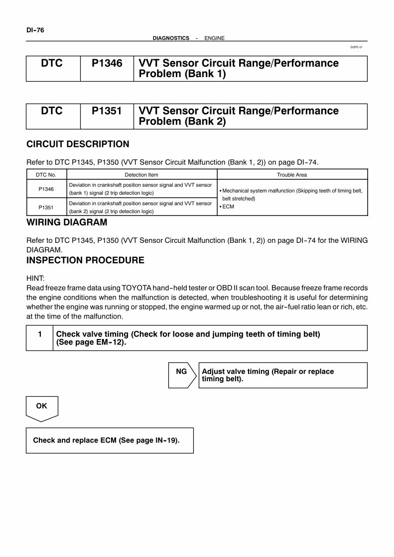
DI--76--DIAGNOSTICS ENGINE
DTC P1346 VVT Sensor Circuit Range/PerformanceProblem (Bank 1)
DTC P1351 VVT Sensor Circuit Range/PerformanceProblem (Bank 2)
CIRCUIT DESCRIPTION
Refer to DTC P1345, P1350 (VVT Sensor Circuit Malfunction (Bank 1, 2)) on page DI--74.
DTC No. Detection Item Trouble Area
P1346Deviation in crankshaft position sensor signal and VVT sensor
(bank 1) signal (2 trip detection logic) SMechanical system malfunction (Skipping teeth of timing belt,
b lt t t h d)
P1351Deviation in crankshaft position sensor signal and VVT sensor
(bank 2) signal (2 trip detection logic)
belt stretched)
SECM
WIRING DIAGRAM
Refer to DTC P1345, P1350 (VVT Sensor Circuit Malfunction (Bank 1, 2)) on page DI--74 for the WIRINGDIAGRAM.
INSPECTION PROCEDURE
HINT:Read freeze frame data using TOYOTAhand--held tester or OBD II scan tool. Because freeze frame recordsthe engine conditions when the malfunction is detected, when troubleshooting it is useful for determiningwhether the engine was running or stopped, the engine warmed up or not, the air--fuel ratio lean or rich, etc.at the time of the malfunction.
1 Check valve timing (Check for loose and jumping teeth of timing belt)(See page EM--12).
NG Adjust valve timing (Repair or replacetiming belt).
OK
Check and replace ECM (See page IN--19).
DI2PE--01

A03980
Oil Control Valve (Bank 1)
1
2
L--W
L--B
ECM
OCV+
OCV--
OCR+
OCR--
20
19
19
28
E14
E11
Oil Control Valve (Bank 2)
G--W1
2
E14
E11
G--B
--DIAGNOSTICS ENGINEDI--77
DTC P1349 VVT System Malfunction (Bank 1)
DTC P1354 VVT System Malfunction (Bank 2)
CIRCUIT DESCRIPTION
VVT system controls the intake valve timing to proper timing in response to driving condition.ECM controls OCV (Oil Control Valve) to make the intake valve timing properly, and, oil pressure controlledwith OCV is supplied to the VVT controller, and then, VVT controller changes relative position between thecamshaft and the crankshaft.
DTC No. DTC Detecting Condition Trouble Area
P1349
P1354
Condition (a) or (b) continues for after the engine is
warmed up and engine speed at 400 ∼ 4,000 rpm :
(a) Valve timing does not change from of current valve
timing
(b) Current valve timing is fixed
SValve timing
SOil control valve
SVVT controller assembly
SECM
WIRING DIAGRAM
DI2PF--01

DI--78--DIAGNOSTICS ENGINE
INSPECTION PROCEDURE
HINT:S If DTC P1349 is displayed, check left bank VVT system circuit.S If DTC P1354 is displayed, check right bank VVT system circuit.S Read freeze frame data using TOYOTA hand--held tester or OBD II scan tool. Because freeze frame
records the engine conditions when the malfunction is detected, when troubleshooting it is useful fordetermining whether the engine was running or stopped, the engine warmed up or not, the air--fuelratio lean or rich, etc. at the time of the malfunction.
TOYOTA hand--held tester
1 Check valve timing (See page EM--12).
NG Repair valve timing.
OK
2 Check operation of OCV.
PREPARATION:(a) Start the engine and warmed it up.(b) Connect the TOYOTA hand--held tester and select VVT from ACTIVE TEST menu.CHECK:Check the engine speed when operate the OCV by the TOYOTA hand--held tester.OK:
OCV is OFF:Normal engine speedOCV is ON:Rough idle or engine stall
OK VVT system is OK.*
*:DTCP1349andP1354are also output after the foreign objectis caught in some part of the system in the engine oil and thesystem returns to normal in a short time. As ECM controls sothat foreign objects are ejected, there is no problem about VVT.There is also no problem since the oil filter should get the for-eign object in the engine oil.
NG

A02397
OCV SignalWaveform
1 m sec./Division
5 V/Division
GND
(A) (A) (A)
A02852
--DIAGNOSTICS ENGINEDI--79
3 Check voltage between terminals OCV+ and OCV-- of ECM connector.
Reference: INSPECTION USING OSCILLOSCOPETurn the ignition switchON, checkwaveformbetween terminalsOCV+ and OCV-- of the ECM connector.HINT:S The correct waveform is as shown.S The waveform frequency (A) is lengthened as the engine
speed becomes higher.
NG Check and replace ECM (See page IN--19).
OK
4 Check VVT controller assembly.
PREPARATION:(a) Remove the timing belt (See page EM--12).(b) Remove the cylinder head cover.(c) Remove the oil control valve (See page EM--29).(d) Drain oil into the VVT controller assembly
(See page EM--29).CHECK:Check whether the oil into VVT controller assembly is drainedor not.OK:
The oil into VVT controller assembly is drained.
NG Replace VVT controller assembly, and thengo to step 5.
OK
5 Check oil control valve (See page SF--46).
NG Replace oil control valve, and then go to step 6.
OK

DI--80--DIAGNOSTICS ENGINE
6 Check blockage of oil control valve, oil check valve and oil pipe No.1.
NG Repair or replace.
OK
7 Check whether or not DTC P1349/P1354 is stored.
PREPARATION:(a) Clear the DTC (See page DI--3).(b) Perform simulation test.CHECK:Check whether or not DTC P1349/P1354 is stored (See page DI--3).OK:
DTC P1349/P1354 is not stored
OK VVT system is OK.*
*:DTCP1349andP1354are also output after the foreign objectis caught in some part of the system in the engine oil and thesystem returns to normal in a short time. As ECM controls sothat foreign objects are ejected, there is no problem about VVT.There is also no problem since the oil filter should get the for-eign object in the engine oil.
NG
Replace ECM.
OBD II scan tool (excluding TOYOTA hand--held tester)
1 Check valve timing (See page EM--12).
NG Repair valve timing.
OK

M02628
OCV Connector
(+)(--)
(a)
(b)
M02386
--DIAGNOSTICS ENGINEDI--81
2 Check operation of OCV.
PREPARATION:Start the engine.CHECK:(a) Check the engine speed when disconnect the OCV con-
nector.(b) Check the engine speed when apply battery positive volt-
age between terminals of OCV.RESULT:
Result Check (a) Check (b)
1 Normal engine speed Rough idle or engine stall
2 Except 1
2 Go to step 4.
1

A02397
OCV SignalWaveform
1 m sec./Division
5 V/Division
GND
(A) (A) (A)
A02852
DI--82--DIAGNOSTICS ENGINE
3 Check voltage between terminals OCV+ and OCV-- of ECM connector.
Reference: INSPECTION USING OSCILLOSCOPETurn the ignition switchON, checkwaveformbetween terminalsOCV+ and OCV-- of the ECM connector.HINT:S The correct waveform is as shown.S The waveform frequency (A) is lengthened as the engine
speed becomes higher.
OK VVT system is OK.*
*:DTCP1349andP1354are also output after the foreign objectis caught in some part of the system in the engine oil and thesystem returns to normal in a short time. As ECM controls sothat foreign objects are ejected, there is no problem about VVT.There is also no problem since the oil filter should get the for-eign object in the engine oil.
NG
Check and replace ECM (See page IN--19).
4 Check VVT controller assembly.
PREPARATION:(a) Remove the timing belt (See page EM--12).(b) Remove the cylinder head cover.(c) Remove the oil control valve (See page EM--29).(d) Drain oil into the VVT controller assembly
(See page EM--29).CHECK:Check whether the oil into VVT controller assembly is drainedor not.OK:
The oil into VVT controller assembly is drained.
NG Replace VVT controller assembly, and thengo to step 5.
OK

--DIAGNOSTICS ENGINEDI--83
5 Check oil control valve (See page SF--46).
NG Replace oil control valve, and then go to step 6.
OK
6 Check blockage of oil control valve, oil check valve and oil pipe No.1.
NG Repair or replace.
OK
7 Check whether or not DTC P1349/P1354 is stored.
PREPARATION:(a) Clear the DTC (See page DI--3).(b) Perform simulation test.CHECK:Check whether or not DTC P1349/P1354 is stored (See page DI--3).OK:
DTC P1349/P1354 is not stored
OK VVT system is OK.*
*:DTCP1349andP1354are also output after the foreign objectis caught in some part of the system in the engine oil and thesystem returns to normal in a short time. As ECM controls sothat foreign objects are ejected, there is no problem about VVT.There is also no problem since the oil filter should get the for-eign object in the engine oil.
NG
Replace ECM.

DI--84--DIAGNOSTICS ENGINE
DTC P1633 ECM Malfunction (ETCS Circuit)
CIRCUIT DESCRIPTION
Refer to DTC P1129 (Electric Throttle Control System Malfunction) on page DI--65.
DTC No. DTC Detecting Condition Trouble Area
P1633 ECM malfunction SECM
INSPECTION PROCEDURE
HINT:Read freeze frame data using TOYOTAhand--held tester or OBD II scan tool. Because freeze frame recordsthe engine conditions when the malfunction is detected, when troubleshooting it is useful for determiningwhether the engine was running or stopped, the engine warmed up or not, the air--fuel ratio lean or rich, etc.at the time of the malfunction.
Replace ECM.
DI2PI--01

--DIAGNOSTICS ENGINEDI--85
DTC P1656 OCV Circuit Malfunction (bank 1)
DTC P1663 OCV Circuit Malfunction (bank 2)
CIRCUIT DESCRIPTION
Refer to DTC P1349, P1354 (VVT System Malfunction (Bank 1, 2)) on page DI--77.
DTC No. DTC Detecting Condition Trouble Area
P1656
P1663Open or short in oil control valve circuit
SOpen or short in oil control valve circuit
SOil control valve
SECM
WIRING DIAGRAM
Refer to DTC P1349, P1354 (VVT System Malfunction (Bank 1, 2)) on page DI--77 for theWIRING DIAGRAM.
INSPECTION PROCEDURE
HINT:S If DTC P1656 dysplayed, check left bank OCV circuit.S If DTC P1663 dysplayed, check right bank OCV circuit.S Read freeze frame data using TOYOTA hand--held tester or OBD II scan tool. Because freeze frame
records the engine conditions when the malfunction is detected, when troubleshooting it is useful fordetermining whether the engine was running or stopped, the engine warmed up or not, the air--fuelratio lean or rich, etc. at the time of the malfunction.
TOYOTA hand--held tester
1 Check OCV circuit.
PREPARATION:(a) Start the engine and warmed it up.(b) Connect the TOYOTA hand--held tester and select VVT from ACTIVE TEST menu.CHECK:Check the engine speed when operate the OCV by the TOYOTA hand--held tester.OK:
VVT system is OFF (OCV is OFF):Normal engine speedVVT system is ON (OCV is ON):Rough idle or engine stalled
OK Check for intermittent problems(See page DI--3).
NG
DI2PJ--01

M02629
START
DI--86--DIAGNOSTICS ENGINE
2 Check operation of OCV.
PREPARATION:(a) Start the engine and warmed it up.(b) Disconnect the OCV connector.(c) Apply battery positive voltage between terminals of the
OCV.CHECK:Check the engine speed.OK:
Rough idle or engine stalled.
NG Replace OCV.
OK
3 Check voltage between terminals OCV+ and OCV-- of ECM connector(See page DI--77, step 3).
NG Check and replace ECM (See page IN--19).
OK
4 Check for open and short in harness and connector between OCV and ECM(See page IN--19).
NG Repair or replace.
OK
Check for intermitent problems(See page DI--3).

M02629
START
--DIAGNOSTICS ENGINEDI--87
OBD II scan tool (excluding TOYOTA hand--held tester)
1 Check operation of OCV.
PREPARATION:(a) Start the engine and warmed it up.(b) Disconnect the OCV connector.(c) Apply battery positive voltage between terminals of the
OCV.CHECK:Check the engine speed.OK:
Rough idle or engine stalled
NG Replace OCV.
OK
2 Check voltage between terminals OCV+ and OCV-- of ECM connector(See page DI--77, step 3).
NG Check and replace ECM (See page IN--19).
OK
3 Check for open and short in harness and connector between OCV and ECM(See page IN--19).
NG Repair or replace.
OK
Check for intermitent problems(See page DI--3).

M02959
Battery STA
ECM
E11
17Y--R
NeutralPositionSwitch
Y--R
Starter
Y--RIG Switch4
ConnectorNo.1
StarterRelay
W--B
CircuitBreaker40A
W
R
2
1 3
4
CircuitBreaker50A
AM2 MAIN
R1
ConnectorNo.1
ST
Y--RY--RB
DI--88--DIAGNOSTICS ENGINE
Starter Signal Circuit
CIRCUIT DESCRIPTION
When the engine is cranked, the intake air flow is slow, so fuel vaporization is poor. A richmixture is thereforenecessary in order to achieve good startability. While the engine is being cranked, the battery positive volt-age is applied to terminal STA of the ECM. The starter signal id mainly used to increase the fuel injectionvolume for the starting injection control and after--start injection control.
WIRING DIAGRAM
DI2PL--01

--DIAGNOSTICS ENGINEDI--89
INSPECTION PROCEDURE
HINT:This diagnostic chart is based on the premise that the engine is cranked normally. If the engine is notcranked, proceed to the problem symptoms table on page DI--3.
TOYOTA hand--held tester
1 Connect TOYOTA hand--held tester and check STA signal.
PREPARATION:(a) Connect the TOYOTA hand--held tester to the DLC3.(b) Turn the ignition switch ON and push the TOYOTA hand--held tester main switch ON.CHECK:Read STA signal on the TOYOTA hand--held tester while starter operates.OK:
Ignition Switch Position ON START
STA signal OFF ON
OK Proceed to next circuit inspection shown onproblem symptoms table (See page DI--3).
NG
2 Check for open in harness and connector between ECM and starter relay(Marking: ST) (See page IN--19).
NG Repair or replace harness or connector.
OK
Check and replace ECM (See page IN--19).

M02301
START
STA (+)
DI--90--DIAGNOSTICS ENGINE
OBD II scan tool (excluding TOYOTA hand--held tester)
1 Check voltage between terminal STA of ECM connector and body ground.
PREPARATION:(a) Remove the wire harness boot.(b) Turn the ignition switch ON.CHECK:Measure voltage between terminal STA of the ECM connectorand body ground, during engine cranking.OK:
Voltage: 6 V or more
OK Proceed to next circuit inspection shown onproblem symptoms table (See page DI--3).
NG
2 Check for open in harness and connector between ECM and starter relay(Marking: ST) (See page IN--19).
NG Repair or replace harness or connector.
OK
Check and replace ECM (See page IN--19).

Battery
E1
B+
E1317
IG Switch
4ConnectorNo.1
EFI MAINRelay
W--B
CircuitBreaker40A
R
R
2
1 3
4
CircuitBreaker120A
AM2 ALT
V
3
ConnectorNo.1
B
V IGN B
EFINo.2B--R B W
E1
W--B
E1510
E1516
E159
MREL
+B
IGSW
EB ED
M02960
B--R
--DIAGNOSTICS ENGINEDI--91
ECM Power Source Circuit
CIRCUIT DESCRIPTION
When the ignition switch is turned ON, battery positive voltage is applied to the terminal IGSW of the ECMand the EFI main relay (Making: EFI) control circuit in the ECM sends a signal to the terminal MREL of theECM switching on the EFI main relay.This signal causes current to flow to the coil, closing the contacts of the EFI main relay and supplying powerto the terminals +B of the ECM.If the ignition switch is turned off, the ECM continues to switch on the EFI main relay for a maximum of 2seconds for the initial setting of the IAC valve.
WIRING DIAGRAM
DI2PM--01

M02302
ON
+B (+)E1 (--)
M02303
ON
IGSW (+)
DI--92--DIAGNOSTICS ENGINE
INSPECTION PROCEDURE
1 Check voltage between terminals + B and E1 of ECM connector.
PREPARATION:(a) Remove the wire harness boot.(b) Turn the ignition switch ON.CHECK:Measure voltage between terminals +BandE1 of the ECMcon-nector.OK:
Voltage: 9 ∼ 14 V
OK Proceed to next circuit inspection shown onProblem symptoms table (See page DI--3).
NG
2 Check for open in harness and connector between terminal E1 of ECM and bodyground (See page IN--19).
NG Repair or replace harness or connector.
OK
3 Check voltage between terminal IGSW of ECM connector and body ground.
PREPARATION:Turn the ignition switch ON.CHECK:Measure voltage between terminal IGSWof the ECM and bodyground.OK:
Voltage: 9 ∼ 14 V
OK Go to step 6.
NG

M03851
IGN Fuse
Fuse Block
--DIAGNOSTICS ENGINEDI--93
4 Check IGN fuse.
PREPARATION:Remove the IGN fuse from the fuse block.CHECK:Check continuity of the IGN fuse.OK:
Continuity
NG Check for short in all harness and componentsconnected to IGN fuse.
OK
5 Check ignition switch.
NG Replace ignition switch.
OK
Check and repair harness and connectorbetween battery and ignition switch, ignitionswitch and ECM (See page IN--19).

M02304
ON
MREL (+)
DI--94--DIAGNOSTICS ENGINE
6 Check voltage between terminal MREL of ECM connector and body ground.
PREPARATION:Turn the ignition switch ON.CHECK:Measure voltage between terminal MREL of the ECM connec-tor and body ground.OK:
Voltage: 9 ∼ 14 V
NG Check and replace ECM (See page IN--19).
OK
7 Check EFI fuse of fuse block.
NG Check for short in all harness and componentsconnected to EFI fuse.
OK
8 Check EFI main relay (Marking: EFI) (See page SF--58).
NG Replace EFI main relay (Marking: EFI).
OK
9 Check for open and short in harness and connector between terminal MREL ofECM and body ground (See page IN--19).
NG Repair and replace harness or connector.
OK
Check and repair harness or connectorbetween EFI fuse and battery.

A01995 A02995 A02441
IACV ACIS Valve closed (VSV: ON)
IntakeManifold
60˚
2,500
Throttle
valve
openingangle
Engine speed (rpm)
4,900
M02964
EFI No.3
EFI MAINRelay
ECM
ACISL--W
2
4
3
1
W--B VSV for ACIS
EFI No.2
From CB ALTFrom ECM
WE14
29
W
--DIAGNOSTICS ENGINEDI--95
ACIS Control VSV Circuit
CIRCUIT DESCRIPTION
This circuit opens and closes the ACIS (Acoustic Control Induction System) Valve in response to the engineload in order to increase the intake efficiency.When the engine speed is 2,500 rpm or less or 4,900 rpm or more and the throttle valve opening angle is60˚ or more, the VSV is OFF, so the ACIS valve is open. All the other times, the ECM turns the VSV ONandcloses the ACIS valve.
WIRING DIAGRAM
DI2PN--01

A00307
ON
VSV is ON VSV is OFF
Air Filter
AirAir
E
F
E
F
BE6653FI7073 FI7074
DI--96--DIAGNOSTICS ENGINE
INSPECTION PROCEDURE
TOYOTA hand--held tester
1 Connect TOYOTA hand--held tester and check operation of VSV for ACIS.
PREPARATION:(a) Connect the TOYOTA hand--held tester to the DLC3.(b) Turn the ignition switch ON and TOYOTA hand--held tes-
ter main switch ON.(c) Select ACTIVE TEST mode on the TOYOTA hand--held
tester.CHECK:Check operation of the VSV when VSV is operated by the TO-YOTA hand--held tester.OK:
VSV is ON:Air from pipe E is flowing out through pipe F.VSV is OFF:Air from pipe E is flowing out through the air filter.
OK Check for vacuum tank (See page SF--55).
NG
2 Check VSV for ACIS (See page SF--63).
NG Replace VSV for ACIS.
OK

M02306
ON
ACIS (+)
--DIAGNOSTICS ENGINEDI--97
3 Check for open and short in harness and connector between EFI main relay(Marking: EFI) and ECM (See page IN--19).
NG Repair or replace harness or connector.
OK
Check and replace ECM (See page IN--19).
OBD II scan tool (excluding TOYOTA hand--held tester)
1 Check VSV for ACIS (See page SF--63).
NG Replace VSV for ACIS.
OK
2 Check voltage between terminal ACIS of ECM connector and body ground.
PREPARATION:(a) Remove the wire harness boot.(b) Turn the ignition switch ON.CHECK:Measure voltage between terminal ACIS of the ECM connectorand body ground.OK:
Voltage: 9 ∼ 14 V
NG Check for open and short in harness andconnector between EFI main relay (Marking:EFI) and ECM (See page IN--19).
OK

DI--98--DIAGNOSTICS ENGINE
3 Check for vacuum tank (See page SF--55).
NG Repair or replace.
OK
Check and replace ECM (See page IN--19).

DIAGNOSTICS
HOW TO PROCEED WITH
TROUBLESHOOTING DI--1. . . . . . . . . . . . . . . . . . . .
CUSTOMER PROBLEM ANALYSIS CHECK DI--2. . .
PRE--CHECK DI--3. . . . . . . . . . . . . . . . . . . . . . . . . . . . .
DIAGNOSTIC TROUBLE CODE CHART DI--13. . . . . .
PARTS LOCATION DI--16. . . . . . . . . . . . . . . . . . . . . . . . .
TERMINALS OF ECM DI--17. . . . . . . . . . . . . . . . . . . . . .
PROBLEM SYMPTOMS TABLE DI--19. . . . . . . . . . . . .
CIRCUIT INSPECTION DI--20. . . . . . . . . . . . . . . . . . . . .

M03242
CompressionGauge
EM0FR--01
--ENGINE MECHANICAL COMPRESSIONEM--1
COMPRESSIONINSPECTIONHINT:If there is lack of power, excessive oil consumption or poor fueleconomy, measure the compression pressure.1. WARM UP AND STOP ENGINEAllow the engine to warm up to normal operating temperature.2. REMOVE SPARK PLUGS
(See page IG--1)3. CHECK CYLINDER COMPRESSION PRESSURE(a) Insert a compression gauge into the spark plug hole.(b) Fully open the throttle.(c) While cranking the engine, measure the compression
pressure.HINT:Always use a fully charged battery to obtain engine speed of250 rpm or more.(d) Repeat steps (a) through (c) for each cylinder.NOTICE:This measurement must be done in as short a time as pos-sible.
Compression pressure:1,226 kPa (12.5 kgf/cm2, 178 psi) or moreMinimum pressure:981 kPa (10.0 kgf/cm2, 142 psi)Difference between each cylinder:98 kPa (1.0 kgf/cm2, 14 psi) or less
(e) If the cylinder compression in oneormore cylinders is low,pour a small amount of engine oil into the cylinder throughthe spark plug hole and repeat steps (a) through (c) forcylinders with low compression.S If adding oil helps the compression, chances are
that the piston rings and/or cylinder bore are wornor damage.
S If pressure stays low, a valve may be sticking orseating is improper, or there may be leakage pastthe gasket.
4. REINSTALL SPARK PLUGS(See page IG--1)

EM0FS--01
M02205
M03271
EM--2--ENGINE MECHANICAL VALVE CLEARANCE
VALVE CLEARANCEINSPECTIONHINT:Inspect and adjust the valve clearancewhen the engine is cold.1. REMOVE V--BANK COVER2. REMOVE INTAKE AIR CONNECTOR ASSEMBLY3. REMOVE NO.3 TIMING BELT COVERS
(See page EM--12)4. REMOVE IGNITION COILS
(See page IG--6)5. REMOVE RH CYLINDER HEAD COVER(a) Disconnect the engine wire clamp from the wire bracket
on the cylinder head cover.(b) Remove the 9 bolts, 9 seal washers and cylinder head
cover.6. REMOVE LH CYLINDER HEAD COVER(a) Disconnect the PCV hose.(b) Disconnect the engine wire clamp from the wire bracket
on the cylinder head cover.(c) Remove the 9 bolts, 9 seal washers and cylinder head
cover.
7. SET NO.1 CYLINDER TO TDC/COMPRESSION(a) Turn the crankshaft pulley, and align its groovewith timing
mark ”0” of the No.1 timing belt cover.
(b) Check that the timing marks of the camshaft timing pul-leys and timing belt rear plates are aligned.
If not, turn the crankshaft 1 revolution (360˚) and align themarkas above.

A02207A02208 A02209
RHCylinderHead
LH Cylinder HeadFront
A02210A02211 A02212
RHCylinderHead
LH Cylinder HeadFront
A02213
--ENGINE MECHANICAL VALVE CLEARANCEEM--3
8. INSPECT VALVE CLEARANCE(a) Check only the valves indicated.
S Using a feeler gauge, measure the clearance be-tween the valve lifter and camshaft.
S Record the out--of--specification valve clearancemeasurements. Theywill be used later to determinethe required replacement adjusting shim.
Valve clearance (Cold):Intake0.15 -- 0.25 mm (0.006 -- 0.010 in.)Exhaust0.25 -- 0.35 mm (0.010 -- 0.014 in.)
(b) Turn the crankshaft 1 revolution (360˚) andalign themarkas above. (See procedure in step 10)
(c) Check only the valves indicated as shown. Measure thevalve clearance. (See procedure in step (a))
9. ADJUST VALVE CLEARANCE(a) Remove the timing belt.
(See page EM--12)(b) Remove the camshafts.
(See page EM--29)(c) Remove the valve lifter and adjusting shim.
(d) Determine the replacement adjusting shim size accordingto these Formula or Charts:S Using a micrometer, measure the thickness of the
removed shim.S Calculate the thickness of a new shim so that the
valve clearance comes within the specified value.T ........... Thickness of removed shimA ........... Measured valve clearanceN ........... Thickness of new shim

EM--4--ENGINE MECHANICAL VALVE CLEARANCE
Intake:N = T + (A -- 0.20 mm (0.008 in.))Exhaust:N = T + (A -- 0.30 mm (0.012 in.))S Select a new shimwith a thickness as close as pos-
sible to the calculated value.HINT:Shims are available in 41 increments of 0.020 mm (0.0008 in.),from 2.00 mm (0.0787 in.) to 2.80 mm (0.1102 in.).(e) Place a new adjusting shim on the valve.(f) Place the valve lifter.(g) Reinstall the camshafts.
(See page EM--52)(h) Reinstall the timing belt.
(See page EM--19)(i) Recheck the valve clearance.10. REINSTALL CYLINDER HEAD COVERS11. REINSTALL IGNITION COILS12. REINSTALL NO.3 TIMING BELT COVERS
(See page EM--19)13. REINSTALL INTAKE AIR CONNECTOR
ASSEMBLY14. REINSTALL V--BANK COVER
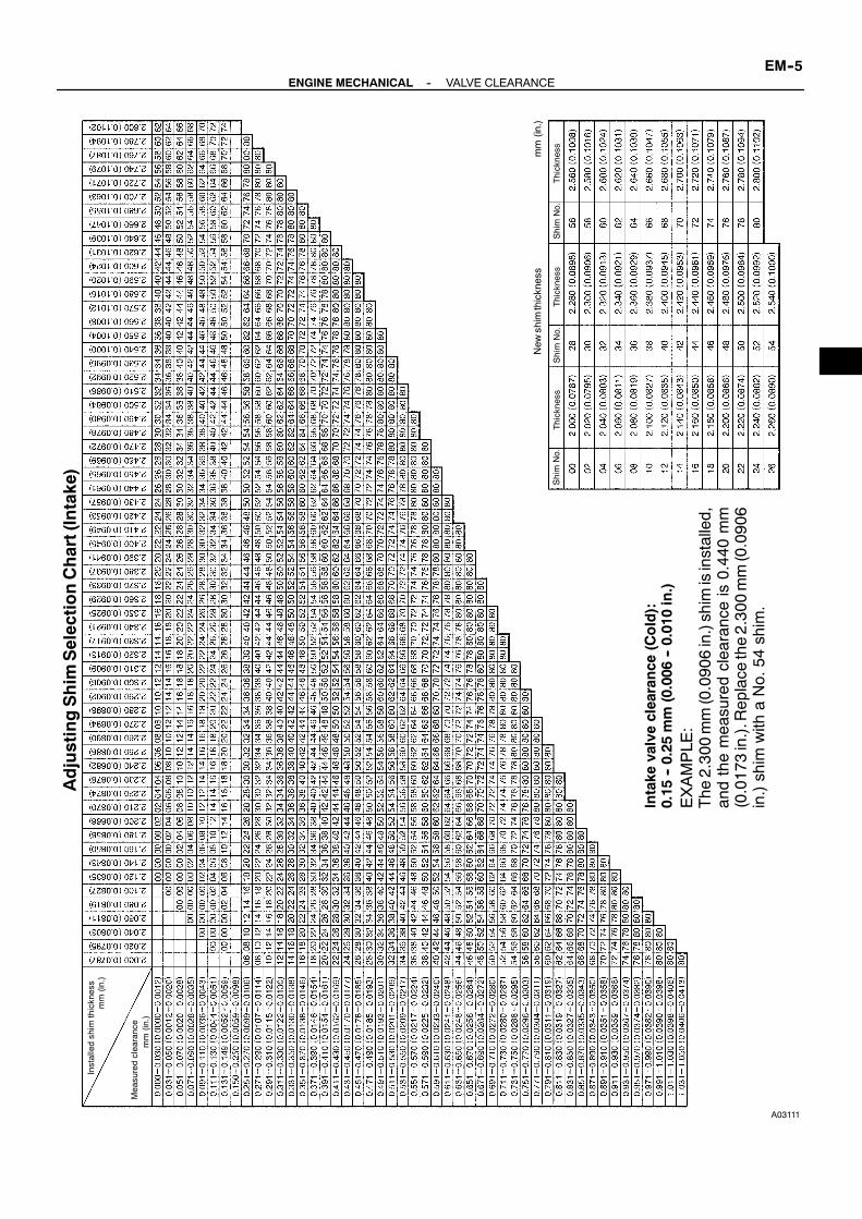
A03111
AdjustingShim
SelectionChart(Intake)
ShimNo.
Installedshim
thickness
mm(in.)
mm(in.)
Measuredclearance
Thickness
New
shimthickness
ShimNo.
Thickness
ShimNo.
Thicknessmm(in.)
Intake
valveclearance
(Cold):
0.15
--0.25
mm(0.006
--0.010in.)
EXAMPLE
:The
2.300mm(0.0906in.)shim
isinstalled,
andthemeasuredclearanceis0.440mm
(0.0173in.).Replace
the2.300mm(0.0906
in.)shim
with
aNo.54
shim.
--ENGINE MECHANICAL VALVE CLEARANCEEM--5

A03112
AdjustingShim
SelectionChart(Exhaust)
Installedshim
thickness
mm(in.)
mm(in.)
Measuredclearance
ShimNo.
Thickness
New
shimthickness
ShimNo.
Thickness
ShimNo.
Thicknessmm(in.)
Exhaustvalveclearance
(Cold):
0.25
--0.35
mm(0.010
--0.014in.)
EXAMPLE
:The
2.300mm(0.0906in.)shim
isinstalled,
andthemeasuredclearanceis0.440mm
(0.0173in.).Replace
the2.300mm(0.0906
in.)shim
with
aNo.44
shim.
EM--6--ENGINE MECHANICAL VALVE CLEARANCE
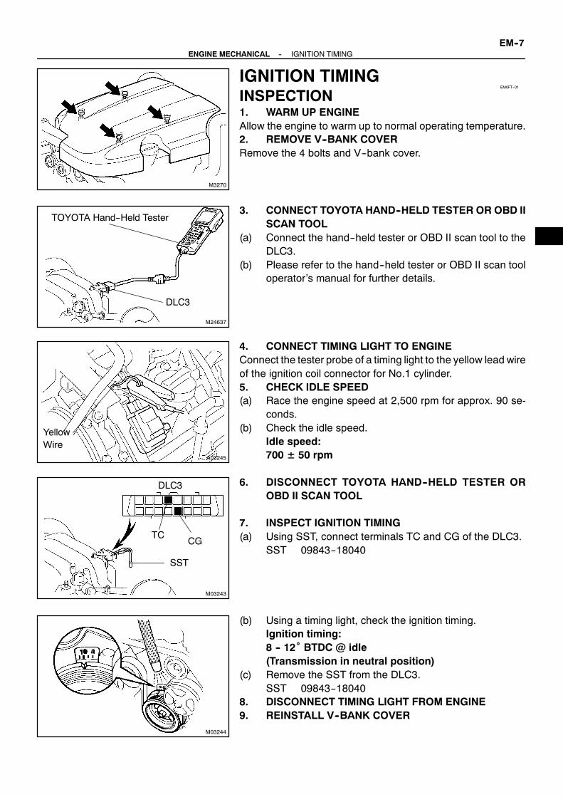
M3270
EM0FT--01
M24637
TOYOTA Hand--Held Tester
DLC3
A03245
YellowWire
M03243
SST
CGTC
DLC3
M03244
--ENGINE MECHANICAL IGNITION TIMINGEM--7
IGNITION TIMINGINSPECTION1. WARM UP ENGINEAllow the engine to warm up to normal operating temperature.2. REMOVE V--BANK COVERRemove the 4 bolts and V--bank cover.
3. CONNECT TOYOTA HAND--HELD TESTER OR OBD IISCAN TOOL
(a) Connect the hand--held tester or OBD II scan tool to theDLC3.
(b) Please refer to the hand--held tester or OBD II scan tooloperator’s manual for further details.
4. CONNECT TIMING LIGHT TO ENGINEConnect the tester probe of a timing light to the yellow lead wireof the ignition coil connector for No.1 cylinder.5. CHECK IDLE SPEED(a) Race the engine speed at 2,500 rpm for approx. 90 se-
conds.(b) Check the idle speed.
Idle speed:700 ± 50 rpm
6. DISCONNECT TOYOTA HAND--HELD TESTER OROBD II SCAN TOOL
7. INSPECT IGNITION TIMING(a) Using SST, connect terminals TC and CG of the DLC3.
SST 09843--18040
(b) Using a timing light, check the ignition timing.Ignition timing:8 -- 12˚ BTDC @ idle(Transmission in neutral position)
(c) Remove the SST from the DLC3.SST 09843--18040
8. DISCONNECT TIMING LIGHT FROM ENGINE9. REINSTALL V--BANK COVER

EM0FU--01
EM--8--ENGINE MECHANICAL IDLE SPEED
IDLE SPEEDINSPECTION1. INITIAL CONDITIONS(a) Engine at normal operating temperature(b) Air cleaner installed(c) All pipes and hoses of air induction system connected(d) All accessories switched OFF(e) All vacuum lines properly connectedHINT:All vacuum hoses should be properly connected.(f) SFI system wiring connectors fully plugged(g) Ignition timing set correctly(h) Transmission in neutral position2. CONNECT TOYOTA HAND--HELD TESTER OR OBD II SCAN TOOL
(See page EM--7)3. INSPECT IDLE SPEED(a) Race the engine speed at 2,500 rpm for approx. 90 seconds.(b) Check the idle speed.
Idle speed:700 ± 50 rpm
If the idle speed is not as specified, check the air intake system.4. DISCONNECT TOYOTA HAND--HELD TESTER OR OBD II SCAN TOOL

EM0FV--01
M03269
V--Bank Cover
Intake Air Connector
--ENGINE MECHANICAL TIMING BELTEM--9
TIMING BELTCOMPONENTS

M04284
Water Bypass Hose
Camshaft PositionSensor Connector
Drive Belt Idler Pulley
Cover Plate
Gasket
RH No.3 TimingBelt Cover
No.2 TimingBelt Cover
Engine Wire
7.5 (80, 66 in.·lbf)
16 (160, 12)
39 (400, 29)
7.5 (80, 66 in.·lbf)
N·m (kgf·cm, ft·lbf) : Specified Torque
18 (185,13)
Water Inlet HousingAssembly
SeaWater Hose
Oil Cooler Pipe
LH No.3 TimingBelt Cover
Gasket
M03268
Sea Water Pump
Timing Belt
TimingBelt Tensioner
Camshaft Timing Pulley
Camshaft TimingPulley
N·m (kgf·cm, ft·lbf) : Specified torque
16 (160, 12)
7.5 (80, 66 in.·lbf)
32 (330, 24)
245 (2,500, 181)
38 (390, 28)
Fan Bracket
EM--10--ENGINE MECHANICAL TIMING BELT

M03266
Generator Wire
Generator Connector
Wire Clamp
Generator
Crankshaft Pulley
DriveBelt Tensioner
No.1 Timing Belt Cover
Timing Belt
Timing Belt Guide(Crankshaft Angle Sensor Plate)
No.2 Idler Pulley
TimingBelt Cover Spacer
Gasket
No.1 Idler Pulley
Crankshaft Timing Pulley
34.5 (350, 25)
34.5 (350, 25)
L
N·m (kgf·cm, ft·lbf) : Specified torqueL Precoated part
39 (400, 29)
Plate Washer
--ENGINE MECHANICAL TIMING BELTEM--11

EM0FW--01
M03270
M03265
M04286
M01867
EM--12--ENGINE MECHANICAL TIMING BELT
REMOVAL1. REMOVE V--BANK COVERRemove the 4 bolts and V--bank cover.2. REMOVE INTAKE AIR CONNECTOR3. REMOVE DRIVE BELT
(See page CH--7)4. REMOVE WATER INLET, INLET HOUSING, No.2 SEA
WATER HOSE, No.3 SEA WATER HOSE AND No.4SEA WATER HOSE ASSEMBLIES(See page CO--5)
5. REMOVE DRIVE BELT IDLER PULLEYRemove the pulley bolt, cover plate and idler pulley.6. REMOVE RH NO.3 TIMING BELT COVERRemove the 3 bolts, cap nut, timing belt cover and gasket.
7. REMOVE LH NO.3 TIMING BELT COVER(a) Remove the bolt and nut, and disconnect the oil cooler
pipe from the timing belt cover and fan bracket.(b) Disconnect the 2 water bypass hoses from the oil cooler
pipe.
(c) Disconnect the engine wire from the 2 wire clamps.(d) Remove the 4 bolts.(e) Disconnect the camshaft position sensor wire from the
wire clamp on the timing belt cover.(f) Disconnect the sensor connector from the connector
bracket.(g) Disconnect the sensor connector.(h) Remove the wire grommet from the timing belt cover.(i) Remove the timing belt cover and gasket.
8. REMOVE NO.2 TIMING BELT COVERRemove the 2 bolts and No.2 timing belt cover.

M00001
A04187
M00684
SST
M00087
A04303
--ENGINE MECHANICAL TIMING BELTEM--13
9. REMOVE SEA WATER PUMP(a) Loosen the hose clamps on sea water hose No. 1(b) Remove the 3 bolts, and remove the seawater pumpwith
the sea water pump bracket.10. REMOVE FAN BRACKETRemove the 2 bolts, 2 nuts and fan bracket.
11. IF RE--USING TIMING BELT, CHECKINSTALLATION MARKS ON TIMING BELT
Check that there are 3 installation marks on the timing belt byturning the crankshaft pulley as shown in the illustration.HINT:If the installationmarks have disappeared, place a new installa-tion mark on the timing belt before removing each part.
12. LOOSEN CRANKSHAFT PULLEY BOLTUsing SST, loosen the pulley bolt.
SST 09213--70010 (90105--08076),09330--00021
13. SET NO.1 CYLINDER TO APPROX. 50°ATDC/COMPRESSION
(a) Turn the crankshaft pulley and align its groove with timingmark ”0” of the No.1 timing belt cover.
(b) Check that the timing marks of the camshaft timing pul-leys and timing belt rear plates aligned.
If not, turn the crankshaft 1 revolution (360˚).

A04114
CrankshaftPulley Bolt
TimingMark
No.2 IdlerPulley Bolt
Approx. 50˚
Turn
A04188
M01876
A03263
EM--14--ENGINE MECHANICAL TIMING BELT
(c) Turn the crankshaft pulley approx. 50˚ clockwise, and putthe timing mark of the crankshaft pulley in line with thecenters of the crankshaft pulley bolt and the idler pulleybolt.
NOTICE:If the timing belt is disengaged, having the crankshaftpulley at the wrong angle can cause the piston head andvalve head to come into contact with each other when youremove the camshaft timing pulley (step 19), causing dam-age. So always set the crankshaft pulley at the correctangle.(d) Remove the crankshaft pulley bolt.NOTICE:Do not turn the crankshaft pulley.14. REMOVE TIMING BELT TENSIONERHINT:S When re--using timing belt:
If the installationmarks havedisappeared, before removethe timing belt, place 2 new installation marks on the tim-ing belt to match the timing marks of the camshaft timingpulleys.
S When replacing timing belt tensioner only:To avoid meshing of the timing pulley and timing belt, se-cure one of them with string. And place matchmarks onthe timing belt and RH camshaft timing pulley.
Alternately loosen the 2 bolts, and remove them, the belt ten-sioner and dust boot.

M04195
Slightly Turn
SST
M03351
HoldSST
A03259
SST
A03251
A03257
10 mmHexagonWrench
PlateWasher
--ENGINE MECHANICAL TIMING BELTEM--15
15. DISCONNECT TIMING BELT FROM CAMSHAFTTIMING PULLEYS
(a) Using SST, loosen the tension spring between the LHandRH camshaft timing pulleys by slightly turning the RHcamshaft timing pulley clockwise.SST 09960--10010 (09962--01000, 09963--00350)
(b) Disconnect the timing belt from the camshaft timing pul-leys.
16. REMOVE CAMSHAFT TIMING PULLEYSUsing SST, remove the 4 bolts and timing pulley. Remove the2 timing pulleys.
SST 09960--10010 (09962--01000, 09963--00350)17. REMOVE GENERATOR
(See page CH--7)18. REMOVE DRIVE BELT TENSIONERRemove the bolt, 2 nuts and belt tensioner.
19. REMOVE CRANKSHAFT PULLEYUsing SST, remove the crankshaft pulley.
SST 09950--50010 (09951--05010, 09952--05010,09953--05010, 09953--05020, 09954--05020)
NOTICE:Do not turn the crankshaft pulley.20. REMOVE NO.1 TIMING BELT COVERRemove the 4 bolts, timing belt cover.21. REMOVE TIMING BELT GUIDE22. REMOVE TIMING BELT COVER SPACER23. REMOVE TIMING BELTHINT:If re--using the belt and the installation mark has disappearedfrom it, place a new installation mark on the timing belt to thematch the dot mark of the crankshaft timing pulley.24. REMOVE NO.2 IDLER PULLEYRemove the bolt and idler pulley.
25. REMOVE NO.1 IDLER PULLEYUsing a 10 mm hexagon wrench, remove the bolt, idler pulleyand plate washer.

A03258
SST
EM--16--ENGINE MECHANICAL TIMING BELT
26. REMOVE CRANKSHAFT TIMING PULLEYUsing SST, remove the timing pulley.
SST 09950--50010 (09951--05010, 09952--05010,09953--05010, 09953--05020, 09954--05010)
NOTICE:Do not turn the timing pulley.
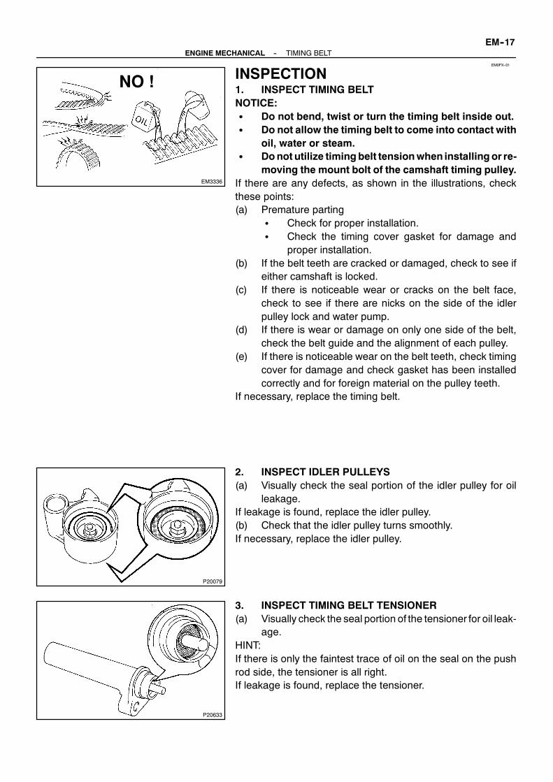
EM0FX--01
EM3336
NO !
P20079
P20633
--ENGINE MECHANICAL TIMING BELTEM--17
INSPECTION1. INSPECT TIMING BELTNOTICE:S Do not bend, twist or turn the timing belt inside out.S Do not allow the timing belt to come into contact with
oil, water or steam.S Donot utilize timingbelt tensionwhen installingor re-
moving the mount bolt of the camshaft timing pulley.If there are any defects, as shown in the illustrations, checkthese points:(a) Premature parting
S Check for proper installation.S Check the timing cover gasket for damage and
proper installation.(b) If the belt teeth are cracked or damaged, check to see if
either camshaft is locked.(c) If there is noticeable wear or cracks on the belt face,
check to see if there are nicks on the side of the idlerpulley lock and water pump.
(d) If there is wear or damage on only one side of the belt,check the belt guide and the alignment of each pulley.
(e) If there is noticeable wear on the belt teeth, check timingcover for damage and check gasket has been installedcorrectly and for foreign material on the pulley teeth.
If necessary, replace the timing belt.
2. INSPECT IDLER PULLEYS(a) Visually check the seal portion of the idler pulley for oil
leakage.If leakage is found, replace the idler pulley.(b) Check that the idler pulley turns smoothly.If necessary, replace the idler pulley.
3. INSPECT TIMING BELT TENSIONER(a) Visually check the seal portion of the tensioner for oil leak-
age.HINT:If there is only the faintest trace of oil on the seal on the pushrod side, the tensioner is all right.If leakage is found, replace the tensioner.

P20634
P20635
Protrusion
EM--18--ENGINE MECHANICAL TIMING BELT
(b) Hold the tensionerwith both hands and push the push rodstrongly as shown to check that it doesn’t move.
If the push rod moves, replace the tensioner.NOTICE:Never hold the tensioner push rod facing downward.
(c) Measure the protrusion of the push rod from the housingend.Protrusion:10.5 -- 11.5 mm (0.413 -- 0.453 in.)
If the protrusion is not as specified, replace the tensioner.4. INSPECT WATER PUMP
(See page CO--6)

EM0FY--01
A04116
SSTInward
A04260
10 mmHexagonWrench
Plate Washer
Adhesive
A03251
A03234
A04117
--ENGINE MECHANICAL TIMING BELTEM--19
INSTALLATION1. INSTALL CRANKSHAFT TIMING PULLEY(a) Align the timing pulley set key with the key groove of the
pulley.(b) Using SST and a hammer, tap in the timing pulley, facing
the flange side inward.SST 09223--46011
2. INSTALL NO.1 IDLER PULLEY(a) Apply adhesive 2 or 3 threads of the pivot bolt.
Adhesive:Part No. 08833--00080, THREE BOND 1344,LOCTITE 242 or equivalent
(b) Using a 10 mm hexagon wrench, install the plate washerand idler pulley with the pivot bolt.Torque: 34.5 N·m (350 kgf·cm, 25 ft·lbf)
(c) Check that the pulley bracket moves smoothly.3. INSTALL NO.2 IDLER PULLEY(a) Install the idler pulley with the bolt.
Torque: 34.5 N·m (350 kgf·cm, 25 ft·lbf)(b) Check that the idler pulley moves smoothly.4. TEMPORARILY INSTALL TIMING BELTNOTICE:The engine should be cold.(a) Remove any oil or water on the crankshaft pulley, oil
pump pulley, water pump pulley, No.1 idler pulley andNo.2 idler pulley, and keep them clean.
NOTICE:Only wipe the pulleys; do not use any cleansing agent.(b) Align the installation mark on the timing belt with the tim-
ing mark of the crankshaft timing pulley.(c) Install the timing belt on the crankshaft timing pulley, No.1
idler pulley and No.2 idler pulley.5. INSTALL TIMING BELT COVER SPACER(a) Install the gasket to the cover spacer.(b) Install the cover spacer.
6. INSTALL TIMING BELT GUIDEInstall the belt guide, facing the cup side outward.7. INSTALL NO.1 TIMING BELT COVERInstall the timing belt cover with the 4 bolts.

S01047
SST
A03256
TimingMark
No.2 Idler Pulley Bolt
CrankshaftPulley
A03350
Hold
SST
M03352
Hold
SST
A03354
Turn
SST
EM--20--ENGINE MECHANICAL TIMING BELT
8. INSTALL CRANKSHAFT PULLEY(a) Align the pulley set key with the key groove of the crank-
shaft pulley.(b) Using SST and a hammer, tap in the crankshaft pulley.
SST 09223--460119. INSTALL DRIVE BELT TENSIONERInstall the belt tensioner with the bolt and 2 nuts.
Torque: 16 N·m (160 kgf·cm, 12 ft·lbf)HINT:Use a bolt 106 mm (4.18 in.) in length.10. INSTALL GENERATOR
(See page CH--17)11. CHECK CRANKSHAFT PULLEY POSITIONCheck that the timing mark of the crankshaft pulley is alignedwith the centers of the crankshaft pulleyand the idler pulleybolt.
12. INSTALL LH CAMSHAFT TIMING PULLEY(a) Align the camshaft timing tube knock pin with the knock
pin groove of the timing pulley.(b) Attach the timing pulley to the camshaft timing tube, fac-
ing the ”L” mark forward.(c) Using SST, install the 4 pulley bolts.
SST 09960--10010 (09962--01000, 09963--00350)Torque: 7.5 N·m (80 kgf·cm, 66 ft·lbf)
13. INSTALL RH CAMSHAFT TIMING PULLEY(a) Align the camshaft timing tube knock pin with the knock
pin groove of the timing pulley.(b) Attach the timing pulley to the camshaft timing tube, fac-
ing the ”R” mark forward.(c) Using SST, install the 4 pulley bolts.
SST 09960--10010 (09962--01000, 09963--00350)Torque: 7.5 N·m (80 kgf·cm, 66 ft·lbf)
14. CONNECT TIMING BELT TO LH CAMSHAFTTIMING PULLEY
(a) Remove any oil or water on the LHcamshaft timing pulley,and keep it clean.
NOTICE:Only wipe the pulleys; do not use any cleansing agent.(b) Using SST, turn the timing pulley. Align the installation
mark on the timing belt with the timing mark of the timingpulley, and hang the timing belt on the timing pulley.SST 09960--10010 (09962--01000, 09963--00350)

A03353
Turn
Tension
SST
M03355
Turn
SST
P20636
1.27 mmHexagonWrench
A03262
1.27 mmHexagonWrench
M00087
--ENGINE MECHANICAL TIMING BELTEM--21
(c) Using SST, turn the LH camshaft timing pulley counter-clockwise until there is tension between the crankshafttiming pulley and LH camshaft timing pulley.SST 09960--10010 (09962--01000, 09963--00350)
15. CONNECT TIMING BELT TO RH CAMSHAFTTIMING PULLEY
(a) Remove any oil or water on theRHcamshaft timing pulleyand water pump pulley, and keep them clean.
NOTICE:Only wipe the pulleys; do not use any cleansing agent.(b) Using SST, turn the timing pulley. Align the installation
mark on the timing belt with the timing mark of the timingpulley, and hang the timing belt on the timing pulley.SST 09960--10010 (09962--01000, 09963--00350)
16. SET TIMING BELT TENSIONER(a) Using a press, slowly press in the push rod using 981 --
9,807 N (100 -- 1,000 kgf, 220 -- 2,205 lbf) of pressure.(b) Align the holes of the push rod and housing, pass a 1.27
mm hexagon wrench through the holes to keep the set-ting position of the push rod.
(c) Release the press.(d) Install the dust boot to the belt tensioner.
17. INSTALL TIMING BELT TENSIONER(a) Temporarily install the belt tensioner with the 2 bolts.(b) Alternately tighten the 2 bolts.
Torque: 26 N·m (270 kgf·cm, 19 ft·lbf)(c) Using pliers, remove the 1.27 mm hexagon wrench from
the belt tensioner.
18. CHECK VALVE TIMING(a) Temporarily install the crankshaft pulley bolt.(b) Slowly turn the crankshaft pulley 2 revolutions from TDC
to TDC.NOTICE:Always turn the crankshaft pulley clockwise.

A04303
M00684
SST
M01891A
B
M00001
EM--22--ENGINE MECHANICAL TIMING BELT
(c) Check that each pulley aligns with the timing marks asshown in the illustration.
If the timing marks do not align, remove the timing belt and rein-stall it.
19. TIGHTEN CRANKSHAFT PULLEY BOLTUsing SST, install the pulley bolt.
SST 09213--70010 (90105--08076),09330--00021
Torque: 245 N·m (2,500 kgf·cm, 181 ft·lbf)
20. INSTALL FAN BRACKET(a) Install the fan bracket with the 2 bolts and 2 nuts.
Torque:12 mm head16 N·m (160 kgf·cm, 12 ft·lbf)14 mm head32 N·m (330 kgf·cm, 24 ft·lbf)
HINT:Each bolt length is indicated in the illustration.Bolt Length:
106 mm (4.17 in.) for 12 mm head (A)114 mm (4.49 in.) for 14 mm head (B)
21. INSTALL SEA WATER PUMP(a) Install the sea water pump bracket and sea water pump
with the 3 bolts.Torque: 38 N.m (390 kgf.cm, 28 ft.lbf)
(b) Secure sea water hose No. 1 with the hose clamp.Torque: 2.5 N.m (25 kgf.cm, 22 ft.lbf)

M03265
M01867
M04286
--ENGINE MECHANICAL TIMING BELTEM--23
22. INSTALL NO.2 TIMING BELT COVERInstall the No.2 timing belt cover with the 2 bolts.
Torque: 16 N·m (160 kgf·cm, 12 ft·lbf)23. INSTALL RH NO.3 TIMING BELT COVER(a) Install the gasket to the timing belt cover.(b) Fit the timing belt cover, matching it with the fan bracket.(c) Install the timing belt cover with the 3 bolts and cap nut.
Torque: 7.5 N·m (80 kgf·cm, 66 in.·lbf)
24. INSTALL LH NO.3 TIMING BELT COVER(a) Install the gasket to the timing belt cover.(b) Run the camshaft position sensor wire through the timing
belt cover hole.(c) Fit the timing belt cover, matching it with the fan bracket.(d) Install the 4 bolts.
Torque: 7.5 N·m (80 kgf·cm, 66 in.·lbf)(e) Install the wire grommet to the timing belt cover.(f) Install the sensor connector to the connector bracket.(g) Connect the sensor connector.(h) Install the sensor wire to the wire clamp on the timing belt
cover.(i) Install the engine wire to the 2 wire clamps on the timing
belt cover.
(j) Connect the 2 water bypass hoses to the oil cooler pipe.(k) Install the oil cooler pipe with the bolt and nut to the timing
belt cover and fan bracket.Torque: 7.5 N·m (80 kgf·cm, 66 in.·lbf)
25. INSTALL DRIVE BELT IDLER PULLEYInstall the idler pulley and cover plate with the bolt.
Torque: 37 N·m (380 kgf·cm, 27 ft·lbf)26. INSTALL WATER INLET, INLET HOSING, No.2 SEA
WATER HOSE, No.3 SEA WATER HOSE, AND No.4SEA WATER HOSE ASSEMBLIES(See page CO--7)
27. INSTALL DRIVE BELT(See page CH--17)
28. INSTALL INTAKE AIR CONNECTOR29. INSTALL V--BANK COVER

EM0FZ--01
M03269
V--Bank Cover
Intake Air Connector
EM--24--ENGINE MECHANICAL CYLINDER HEAD
CYLINDER HEADCOMPONENTS

M04284
Water Bypass Hose
Camshaft PositionSensor Connector
Drive Belt Idler Pulley
Cover Plate
Gasket
RH No.3 TimingBelt Cover
No.2 TimingBelt Cover
Engine Wire
7.5 (80, 66 in.·lbf)
16 (160, 12)
39 (400, 29)
7.5 (80, 66 in.·lbf)
N·m (kgf·cm, ft·lbf) : Specified Torque
18 (185,13)
Water Inlet HousingAssembly
SeaWater Hose
Oil Cooler Pipe
LH No.3 TimingBelt Cover
Gasket
M03268N·m (kgf·cm, ft·lbf) : Specified torque
Sea Water Pump
Timing Belt
TimingBelt Tensioner
Camshaft Timing Pulley
Camshaft TimingPulley
16 (160, 12)
7.5 (80, 66 in.·lbf)
32 (330, 24)
245 (2,500, 181)
38 (390, 28)
Fan Bracket
--ENGINE MECHANICAL CYLINDER HEADEM--25

M04820z Non--reusable part
Accelerator PedalPosition SensorConnector
ECT Sensor Connector
V--Bank Cover Bracketwith Noise Filter
Throttle PositionSensor Connector
Injector Connector
VVT Sensor 2Connector
Ignition CoilConnector
ECT Sender GaugeConnector
Front Water BypassJoint
VVT Sensor 2
Ignition Coil
RH No.1 Timing BeltRear Plate
Rear WaterBypass Joint
VSV Connectorfor ACIS
Throttle Control MotorConnector
VVTSensor 1
z Gasket
zO--Ring
z Gasket
V--Bank Cover Bracket
V--Bank CoverBracket
Noise FilterConnector
Camshaft TimingOil Control ValveConnector
Water BypassHose
Intake Manifold Assembly
VVT Sensor 1 Connector
Fuel Pressure PulsationDamper
Throttle ControlCable Bracket
z Gasket
Fuel InletPipe
Wiring HarnessClamp Bracket
Fuel Hose
z Gasket
LH No.2 Timing BeltRear Plate
LH No.1 Timing BeltRear Plate
RH No.2 Timing BeltRear Plate
z Gasket
EM--26--ENGINE MECHANICAL CYLINDER HEAD

M04263
RH Camshaft Timing Oil Control Valve
RH Cylinder Head Cover
LH Camshaft Timing Oil Control Valve
LH Cylinder Head Cover
Camshaft Timing TubeCamshaftDrive Gear
BearingCap
Oil FeedPipe
Gasket
Bearing Cap
z Camshaft Oil Seal
Gasket
CamshaftTimingTube
zCamshaftOil Seal
LH IntakeCamshaft
LH ExhaustCamshaft
Camshaft Gear Spring
Camshaft Sub GearWave Washer
Snap Ring
Camshaft TimingOil Control Valve Filter
EngineHanger
RH ExhaustCamshaft
Camshaft Gear Spring
Camshaft Sub GearSnap Ring
Camshaft TimingOil Control ValveFilter
CamshaftHousing Plug
Semi--CircularPlug
RH Cylinder Head
z RH Cylinder HeadGasket
RH ExhaustManifold Oil Dipstick and Guide
for Engine
z LH Cylinder HeadGasket
LH Cylinder Head
Ground Cable
Semi--Circular Plug
Camshaft HousingPlug
z Non--reusable part
CamshaftDrive Gear
BearingCap
RH Intake Camshaft
z O--Ringz O--Ring
Spark Plug
zSpark PlugTube Gasket
1st 39 (400, 29)2nd Turn 90˚
16 (160, 12)
16 (160, 12)7.5 (80, 66 in.·lbf)
78 (790, 58)
N·m (kgf·cm, ft·lbf) : Specified torque
Wave Washer
zGasket
44 (450, 32)z×8
z×8
LH ExhaustManifold
zGasket
--ENGINE MECHANICAL CYLINDER HEADEM--27

M04264
RH Cylinder Head
Valve Lifter
Keeper
Spring Retainer
Valve Spring
z Oil Seal
Valve
LH Cylinder Head
z Valve Guide Bushing
Adjusting Shim
Spring Seat
z Non--reusable part
N·m (kgf·cm, ft·lbf) : Specified Torque
EM--28--ENGINE MECHANICAL CYLINDER HEAD

EM0G0--01
A02844
M00002
--ENGINE MECHANICAL CYLINDER HEADEM--29
REMOVAL1. DISCONNECT TIMING BELT FROM CAMSHAFT
TIMING PULLEYS(See page EM--12)
2. REMOVE CAMSHAFT TIMING PULLEYS(See page EM--12)
3. REMOVE CAMSHAFT POSITION SENSOR(See page IG--9)
4. REMOVE IGNITION COILS(See page IG--6)
5. REMOVE TIMING BELT REAR PLATES(a) Remove the 3 bolts, stud bolt, and RHNo.1 and No.2 tim-
ing belt rear plates.(b) Disconnect the wire clamp from the LH timing belt rear
plate.(c) Remove the 3 bolts, LH No.1 and No.2 timing belt rear
plates.NOTICE:S Be careful not to drop anything inside the timing belt
cover.S Do not allow the belt to come into contactwith oil, wa-
ter or dust.6. DISCONNECT FUEL INLET PIPE AND HOSE(a) Remove the fuel pressure pulsation damper, then remove
the fuel inlet pipe.(b) Disconnect the No. 4 fuel hose.7. DISCONNECT THROTTLE CABLE8. REMOVE V--BANK COVER BRACKETS(a) Remove the nut and LH front V--bank cover bracket from
the engine hanger.(b) Remove the bolt, nut and throttle control cable bracket
from the intake manifold.(c) Remove the bolt and LH rear V--bank cover bracket from
the intake manifold.(d) Remove the nut and RH rear V--bank cover bracket from
the engine hanger.

M04265
(1)
(2)
M02847
(4)
(3)
M00033
M00034
EM--30--ENGINE MECHANICAL CYLINDER HEAD
9. REMOVE INTAKE MANIFOLD ASSEMBLY(a) Disconnect these connectors:
S Throttle position sensor connectorS Accelerator pedal position sensor connectorS Throttle control motor connectorS VSV connector for ACISS 8 injector connectorsS Noise filter connectorS Camshaft timing oil control valve connector
(b) Disconnect these hoses:(1) PCV hose from PCV valve on LH cylinder head(2) Oil drain hose (from intake manifold)
(3) No.1 water bypass hose (from front water bypassjoint) from throttle body
(4) No.7 water bypass hose (from water inlet housing)from throttle body
(c) Disconnect the 2 wire clamp from the throttle body.
(d) Disconnect the engine wire.(1) Remove the bolt and wire clamp bracket from the
LH cylinder head cover.
(2) Remove the bolt and wire clamp bracket from theRH cylinder head cover.
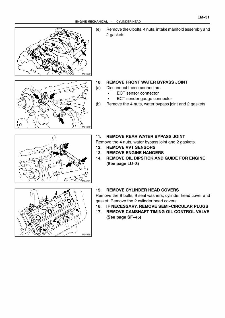
M04269
M04270
M04271
M04475
--ENGINE MECHANICAL CYLINDER HEADEM--31
(e) Remove the 6 bolts, 4 nuts, intakemanifold assemblyand2 gaskets.
10. REMOVE FRONT WATER BYPASS JOINT(a) Disconnect these connectors:
S ECT sensor connectorS ECT sender gauge connector
(b) Remove the 4 nuts, water bypass joint and 2 gaskets.
11. REMOVE REAR WATER BYPASS JOINTRemove the 4 nuts, water bypass joint and 2 gaskets.12. REMOVE VVT SENSORS13. REMOVE ENGINE HANGERS14. REMOVE OIL DIPSTICK AND GUIDE FOR ENGINE
(See page LU--8)
15. REMOVE CYLINDER HEAD COVERSRemove the 9 bolts, 9 seal washers, cylinder head cover andgasket. Remove the 2 cylinder head covers.16. IF NECESSARY, REMOVE SEMI--CIRCULAR PLUGS17. REMOVE CAMSHAFT TIMING OIL CONTROL VALVE
(See page SF--45)

A04272
No.2 Idler Pulley Bolt
TimingMark
CrankshaftPulley Bolt
A02852
Rotate (25˚)
A02853Service Bolt
A02854
10˚
EM--32--ENGINE MECHANICAL CYLINDER HEAD
18. REMOVE CAMSHAFTSNOTICE:Since the thrust clearance of the camshaft is small, thecamshaftmust be kept level while it is being removed. If thecamshaft is not kept level, the portion of the cylinder headreceiving the shaft thrust may crack or be damaged, caus-ing the camshaft to seize or break. To avoid this, the follow-ing steps should be carried out.(a) Check the crankshaft pulley position.
Check that the timing mark of the crankshaft pulley is inaligned with the centers of the crankshaft pulley bolt andidler pulley bolt.
NOTICE:Having the crankshaft pulley at the wrong angle can causethe piston head and valve head to come into contact witheach other when you remove the camshaft, causing dam-age. So always set the crankshaft pulley at the correctangle.
(b) Rotate the VVT--i pulley from left to right 2 to 3 timeswithinits range of movement (25˚ <50˚ CA> ) and use a wastecloth to collect the oil from the camshaft timing oil controlvalve installation hole.
NOTICE:Approximately 20 cc (1.2 cu in.) of oil will be ejected, sotake care not to spill it.
(c) Remove the RH camshafts.(1) Boring the service bolt hole of the sub--gear upward
by turning the hexagon wrench head portion of theexhaust camshaft with a wrench.
(2) Secure the sub--gear to themain gearwith a servicebolt.
Recommended service bolt:
Thread diameter 6 mm
Thread pitch 1.0 mm
Bolt length 16 -- 20 mm
HINT:When removing the camshafts, make sure that the torsionalspring force of the sub--gear has been eliminated by the aboveoperation.
(3) Set the timing mark (1 dot mark) of the camshaftmain gear at approx. 10˚ angle by turning the hexa-gon wrench head portion of the exhaust camshaftwith a wrench.

A02855
614
481
10
16 18
12
2
19
20
2122
9
15 17
11
513
37
A02856
A02857
Align
A02858
6 14
4 81
10
1618
2
192021
22
9
5 13
3 712
17
11
15
A02859
--ENGINE MECHANICAL CYLINDER HEADEM--33
(4) Uniformly loosen and remove the 22 bearing capbolts in several passes, in the sequence shown.
(5) Remove the oil feed pipe, 9 bearing caps, camshafttiming oil control valve filter and camshafts.
(d) Remove the LH camshafts.(1) Boring the service bolt hole of the sub--gear upward
by turning the hexagon wrench head portion of theexhaust camshaft with a wrench.
(2) Secure the sub--gear to themain gearwith a servicebolt.
Recommended service bolt:
Thread diameter 6 mm
Thread pitch 1.0 mm
Bolt length 16 -- 20 mm
HINT:When removing the camshaft, make sure that the torsionalspring force of the sub--gear has been eliminated by the aboveoperation.
(3) Align the timing mark (2 dot marks) of the camshaftdrive gear by turning the hexagonwrench head por-tion of the exhaust camshaft with a wrench.
(4) Uniformly loosen and remove the 22 bearing capbolts in several passes, in the sequence shown.
(5) Remove the oil feed pipe, 9 bearing caps, camshafttiming oil control valve filter and camshafts.
HINT:Arrange the bearing caps in correct order.19. IF NECESSARY REMOVE CAMSHAFT HOUSING
PLUGS
20. DISASSEMBLE EXHAUST CAMSHAFTS(a) Mount the hexagon wrench head portion of the camshaft
in a vise.NOTICE:Be careful not to damage the camshaft.

A02850
SST
Service Bolt
Turn
A02861
A02862
Do not Remove
A02863
A02865
EM--34--ENGINE MECHANICAL CYLINDER HEAD
(b) Using SST, turn the sub--gear clockwise, and remove theservice bolt.SST 09960--10010 (09962--01000, 09963--00500)
(c) Using snap ring pliers, remove the snap ring.(d) Remove these parts:
S Wave washerS Camshaft sub--gearS Camshaft gear spring
HINT:Arrange the camshaft sub--gears and gear spring (RH and LHsides).
21. REMOVE CAM SHAFT TIMING TUBES(a) Mount the hexagon wrench head portion of the intake
camshaft in a vise.NOTICE:S Be careful not to damage the camshaft.S The 4 bolts shown in the illust ration determine the
backlash of the gear in the timing tube, so do not re-move them. If any of the 4 bolts are removed, installa new camshaft timing tube assembly.
(b) Remove the straight screw plug and seal washer.(c) Using a 10 mmhexagon wrench, and remove the set bolt
and camshaft timing tube.
(d) Using a 5 mm hexagon wrench, and remove the 4 bolts,camshaft drive gear and oil seal.
NOTICE:Be careful not to damage the camshaft timing tube.

M04275
M04276
M02868
A02869
RH Cylinder Head
LH Cylinder Head Front
1 9
10 8
7 6
5
4
3 2
1
351082
4 6 9 7
--ENGINE MECHANICAL CYLINDER HEADEM--35
22. REMOVERHEXHAUSTMANIFOLDFROMCYLINDERHEAD
Remove the 8 nuts, exhaust manifold and gasket.
23. REMOVE LH EXHAUSTMANIFOLD FROMCYLINDERHEAD
Remove the 8 nuts, exhaust manifold and gasket.24. REMOVE OIL COOLER FOR TRANSMISSION
(See page EM--69)25. REMOVE SPARK PLUGS
26. REMOVE CYLINDER HEAD(a) Remove the bolt, and disconnect the ground cable from
the LH cylinder head.
(b) Uniformly loosen the 10 cylinder head bolts on one sideof each cylinder head in several passes, in the sequenceshown, then do the other side as shown. Remove the 20cylinder head bolts and plate washers.
NOTICE:S Cylinder head warpage or cracking could result from
removing bolts in incorrect order.

A02872
RH Cylinder Head
LH Cylinder Head
A
A
M04274
EM--36--ENGINE MECHANICAL CYLINDER HEAD
S Do not drop the plate washer for cylinder head boltinto portion A of the cylinder head. If dropped intoportion A, the plate washer will pass through the cyl-inder head and cylinder block into the oil pan.
(c) Lift the cylinder head from the dowels on the cylinderblock, and place the 2 cylinder heads on wooden blockson a bench.
HINT:If the cylinder head is lift off, pry between the cylinder head andcylinder block with a screwdriver.NOTICE:S Be careful not to damage the contact surfaces of the
cylinder head and cylinder block.S The cylinder head should not be tilted so as to secure
the valve lifter. If the cylinder head is tilted, removethe valve lifter and check that the adjusting shim isset correctly.

EM0G1--01
A03191
SST
A03192
--ENGINE MECHANICAL CYLINDER HEADEM--37
DISASSEMBLY1. REMOVE VALVE LIFTERS AND SHIMSHINT:Arrange the valve lifters and shims in correct order.2. REMOVE VALVES(a) Using SST, compress the valve spring and remove the 2
keepers.SST 09202--70020
(b) Remove these parts:S Spring retainerS Valve springS ValveS Spring seat
HINT:Arrange the valves, valve springs, spring seats and spring re-tainers incorrect order.(c) Using needle--nose pliers, remove the oil seal.
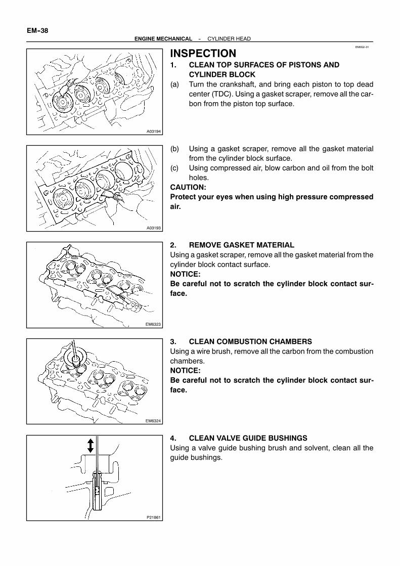
EM0G2--01
A03194
A03193
EM6323
EM6324
P21861
EM--38--ENGINE MECHANICAL CYLINDER HEAD
INSPECTION1. CLEAN TOP SURFACES OF PISTONS AND
CYLINDER BLOCK(a) Turn the crankshaft, and bring each piston to top dead
center (TDC). Using a gasket scraper, remove all the car-bon from the piston top surface.
(b) Using a gasket scraper, remove all the gasket materialfrom the cylinder block surface.
(c) Using compressed air, blow carbon and oil from the boltholes.
CAUTION:Protect your eyes when using high pressure compressedair.
2. REMOVE GASKET MATERIALUsing a gasket scraper, remove all the gasket material from thecylinder block contact surface.NOTICE:Be careful not to scratch the cylinder block contact sur-face.
3. CLEAN COMBUSTION CHAMBERSUsing a wire brush, remove all the carbon from the combustionchambers.NOTICE:Be careful not to scratch the cylinder block contact sur-face.
4. CLEAN VALVE GUIDE BUSHINGSUsing a valve guide bushing brush and solvent, clean all theguide bushings.

EM6325
A02876A02877A02878 A02879
EM6327
EM0580
--ENGINE MECHANICAL CYLINDER HEADEM--39
5. CLEAN CYLINDER HEADUsing a soft brush and solvent, thoroughly clean the cylinderhead.
6. INSPECT FOR FLATNESSUsing a precision straight edge and feeler gauge, measure thesurfaces contacting the cylinder block and the manifolds forwarpage.
Maximum warpage:0.10 mm (0.0039 in.)
If warpage is greater than maximum, replace the cylinder head.
7. INSPECT FOR CRACKSUsing a dye penetrant, check the combustion chamber, intakeports, exhaust ports and cylinder block surface for cracks.If cracked, replace the cylinder head.
8. CLEAN VALVES(a) Using a gasket scraper, chip off any carbon from the valve
head.(b) Using a wire brush, thoroughly clean the valve.

P21862
Z00052
Z00054
44.5˚
EM0181
Margin Thickness
EM--40--ENGINE MECHANICAL CYLINDER HEAD
9. INSPECT VALVE STEMS AND GUIDE BUSHINGS(a) Using a caliper gauge,measure the inside diameter of the
guide bushing.Bushing inside diameter:5.510 -- 5.530 mm (0.2169 -- 0.2177 in.)
(b) Using a micrometer, measure the diameter of the valvestem.Valve stem diameter:Intake5.470 -- 5.485 mm (0.2154 -- 0.2159 in.)Exhaust5.465 -- 5.480 mm (0.2152 -- 0.2157 in.)
(c) Subtract the valve stem diameter measurement from theguide bushing inside diameter measurement.Standard oil clearance:Intake0.025 -- 0.060 mm (0.0010 -- 0.0024 in.)Exhaust0.030 -- 0.065 mm (0.0012 -- 0.0026 in.)Maximum oil clearance:Intake0.08 mm (0.0031 in.)Exhaust0.10 mm (0.0039 in.)
If the clearance is greater thanmaximum, replace the valve andguide bushing. (See Page EM--50)10. INSPECT AND GRIND VALVES(a) Grind the valve enough to remove pits and carbon.(b) Check that the valve is ground to the correct valve face
angle.Valve face angle:44.5˚
(c) Check the valve head margin thickness.Standard margin thickness:1.0 mm (0.039 in.)Minimum margin thickness:0.5 mm (0.020 in.)
If the margin thickness is less than minimum, replace the valve.

EM2534
Overall Length
EM0255
EM6330
45˚ Carbide Cutter
Z00055
Width
Z03988
45˚ 30˚
1.0 -- 1.4 mm
--ENGINE MECHANICAL CYLINDER HEADEM--41
(d) Check the valve overall length.Standard overall length:Intake: 94.80 -- 95.30 mm (3.7323 -- 3.7520 in.)Exhaust: 94.85 -- 95.35 mm (3.7342 -- 3.7539 in.)Minimum overall length:Intake: 94.55 mm (3.7224 in.)Exhaust: 94.60 mm (3.7244 in.)
If the overall length is less than minimum, replace the valve.
(e) Check the surface of the valve stem tip for wear.If the valve stem tip is worn, resurface the tip with a grinder orreplace the valve.NOTICE:Do not grind off more than minimum.
11. INSPECT AND CLEAN VALVE SEATS(a) Using a 45˚ carbide cutter, resurface the valve seats. Re-
move only enough metal to clean the seats.
(b) Check the valve seating position.Apply a light coat of prussian blue (or white lead) to thevalve face. Lightly press the valve against the seat. Donotrotate valve.
(c) Check the valve face and seat for the following:S If blue appears 360˚ around the face, the valve is
concentric. If not, replace the valve.S If blue appears 360˚ around the valve seat, the
guide and face are concentric. If not, resurface theseat.
S Check that the seat contact is in the middle of thevalve face with the following width:
1.0 -- 1.4 mm (0.039 -- 0.055 in.)If not, correct the valve seats as follows:
S If the seating is too high on the valve face, use 30˚and 45˚ cutters to correct the seat.

Z03989
60˚ 45˚
1.0 -- 1.4 mm
EM6331
EM0988
Deviation
EM0801
EM0281
EM--42--ENGINE MECHANICAL CYLINDER HEAD
S If the seating is too low on the valve face, use 60˚and 45˚ cutters to correct the seat.
(d) Hand--lap the valve and valve seat with an abrasive com-pound.
(e) After hand--lapping, clean the valve and valve seat.
12. INSPECT VALVE SPRINGS(a) Using a steel square, measure the deviation of the valve
spring.Maximum deviation:2.0 mm (0.079 in.)
If the deviation is greater than maximum, replace the valvespring.
(b) Using vernier calipers, measure the free length of thevalve spring.Free length:54.05 -- 54.15 mm (2.1279 -- 2.1319 in.)
If the free length is not as specified, replace the valve spring.
(c) Using a spring tester, measure the tension of the valvespring at the specified installed length.Installed tension:204 -- 226 N (20.8 -- 23.0 kgf, 45.9 -- 50.7 lbf)at 35.04 mm (1.3795 in.)
If the installed tension is not as specified, replace the valvespring.

A03202
EM2011
EM2538A02880 A03222
A
A
--ENGINE MECHANICAL CYLINDER HEADEM--43
13. INSPECT CAMSHAFT FOR RUNOUT(a) Place the camshaft on V--blocks.(b) Using a dial indicator, measure the circle runout at the
center journal.Maximum circle runout:0.08 mm (0.0031 in.)
If the circle runout is greater than maximum, replace the cam-shaft.
14. INSPECT CAM LOBESUsing a micrometer, measure the cam lobe height.
Standard cam lobe height:Intake:42.610 -- 42.710 mm (1.6776 -- 1.6815 in.)Exhaust:42.630 -- 42.730 mm (1.6783 -- 1.6823 in.)Minimum cam lobe height:Intake:42.46 mm (1.6717 in.)Exhaust:42.48 mm (1.6724 in.)
If the cam lobe height is less than minimum, replace the cam-shaft.
15. INSPECT CAMSHAFT JOURNALSUsing a micrometer, measure the journal diameter.
Journal diameter:Intake camshaft (A)30.984 -- 31.000 mm (1.2198 -- 1.2205 in.)Others26.954 -- 26.970 mm (1.0612 -- 1.0618 in.)
If the journal diameter is not as specified, check the oil clear-ance.

A03217
Knock PinRed PaintedMark
GreenPaintedMark
A03203
EM3322
A03216
LH Cylinder Head RH Cylinder Head
Front
MarkA or B
A03204
Plastigage
EM--44--ENGINE MECHANICAL CYLINDER HEAD
16. INSPECT CAMSHAFT TIMING TUBE JOURNALSHINT:There are 2 size of the camshaft timing tube journal diameter,green and red painted mark accordingly. The mark is paintedon the face of the camshaft timing tube.
Using a micrometer, measure the journal diameter.Journal diameter:Green painted mark39.958 -- 39.964 mm (1.5731 -- 1.5734 in.)Red painted mark39.964 -- 39.970 mm (1.5734 -- 1.5736 in.)
If the journal diameter is not as specified, check the oil clear-ance.
17. INSPECT CAMSHAFT GEAR SPRINGUsing vernier calipers, measure the free distance between thespring ends.
Free distance:18.2 -- 18.8 mm (0.712 -- 0.740 in.)
If the free distance is not as specified, replace the gear spring.18. INSPECT CAMSHAFT BEARINGSCheck that bearings for flaking and scoring.If the bearings are damaged, replace the bearing caps and cyl-inder head as a set.19. INSPECTCAMSHAFT TIMING TUBEANDCAMSHAFT
JOURNAL OIL CLEARANCEHINT:There are 2 size of the camshaft timing tube journal oil clear-ance, Marked ”A” and ”B” accordingly. The mark is stamped onthe top of the cylinder heads.(a) Install the camshaft timing tube.
(See page EM--52)(b) Clean the bearing caps and camshaft journals.(c) Place the camshafts on the cylinder head.(d) Lay a strip of Plastigage across each of the camshaft jour-
nals.

A03205
A03206
A03207
--ENGINE MECHANICAL CYLINDER HEADEM--45
(e) Install the bearing caps.(See page EM--52)Torque: 16 N·m (160 kgf·cm, 12 ft·lbf)
NOTICE:Do not turn the camshaft.(f) Remove the bearing caps.
(g) Measure the Plastigage at its widest point.Standard oil clearance:Camshaft timing tube journalMark ”A”0.036 -- 0.050 mm (0.0014 -- 0.0020 in.)Mark ”B”0.038 -- 0.052 mm (0.0015 -- 0.0021 in.)
Others0.030 -- 0.067 mm (0.0012 -- 0.0026 in.)Maximum oil clearance:Camshaft timing tube journal0.085 mm (0.0033 in.)Others0.10 mm (0.0039 in.)
If the oil clearance is greater than maximum, replace the cam-shaft. If necessary, replace the bearing caps and cylinder headas a set.(h) Completely remove the Plastigage.(i) Remove the camshafts.(j) Remove the camshaft timing tube.20. IF NECESSARY REPLACE CAMSHAFT TIMING TUBESelect a camshaft timing tube according to mark on the cylinderhead.
Cylinder Head Camshaft timing tube
Mark ”A” Green painted mark
Mark ”B” Red painted mark
21. INSPECT CAMSHAFT THRUST CLEARANCE(a) Install the camshaft timing tube.
(See page EM--52)(b) Install the camshaft.
(See page EM--52)(c) Using a dial indicator, measure the thrust clearance while
moving the camshaft back and forth.Standard thrust clearance:Intake0.060 -- 0.100 mm (0.0024 -- 0.0039 in.)Exhaust0.040 -- 0.090 mm (0.0016 -- 0.0035 in.)

A03208
A03209
A03201
12.3 -- 12.7mm
A02881
EM--46--ENGINE MECHANICAL CYLINDER HEAD
Maximum thrust clearance:Intake: 0.13 mm (0.0051 in.)Exhaust: 0.12 mm (0.0047 in.)
If the thrust clearance is greater than maximum, replace thecamshaft. If necessary, replace the bearing caps and cylinderhead as a set.(d) Remove the camshafts.(e) Remove the camshaft timing tube.
22. INSPECT CAMSHAFT GEAR BACKLASH(a) Install the camshaft timing tube.
(See page EM--52)(b) Install the camshafts without installing the exhaust cam
sub--gear and front bearing cap.(See page EM--52)
(c) Using a dial indicator, measure the backlash.Standard backlash:0.020 -- 0.200 mm (0.0008 -- 0.0079 in.)Maximum backlash:0.30 mm (0.0188 in.)
If the backlash is greater then maximum, replace the cam-shafts.(d) Remove the camshafts.23. INSPECT VALVE LIFTERS AND LIFTER BORES(a) Using a caliper gauge, measure the lifter bore diameter
of the cylinder head.Lifter bore diameter:31.000 -- 31.016 mm (1.2205 -- 1.2211 in.)
(b) Using a micrometer, measure the lifter diameter at thevalve lifter center line, 12.3 -- 12.7 mm (0.484 -- 0.500 in.)from the valve lifter head.Lifter diameter:30.966 -- 30.976 mm (1.2191 -- 1.2195 in.)
(c) Subtract the lifter diameter measurement from the lifterbore diameter measurement.Standard oil clearance:0.024 -- 0.050 mm (0.0009 -- 0.0020 in.)Maximum oil clearance:0.07 mm (0.0028 in.)
If the oil clearance is greater than maximum, replace the lifter.If necessary, replace the cylinder head.24. INSPECT INTAKE MANIFOLD(a) Upper intake manifold:
Using a precision straight edge and feeler gauge, mea-sure the surface contacting the lower intake manifold forwarpage.Maximum warpage: 0.15 mm (0.0059 in.)
If warpage is greater than maximum, replace the upper intakemanifold.
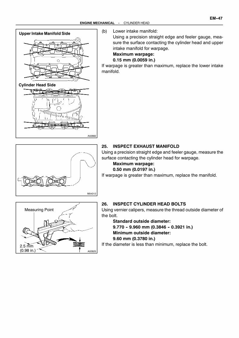
A02882
Upper Intake Manifold Side
Cylinder Head Side
M04312
A02825
Measuring Point
2.5 mm(0.98 in.)
--ENGINE MECHANICAL CYLINDER HEADEM--47
(b) Lower intake manifold:Using a precision straight edge and feeler gauge, mea-sure the surface contacting the cylinder head and upperintake manifold for warpage.Maximum warpage:0.15 mm (0.0059 in.)
If warpage is greater than maximum, replace the lower intakemanifold.
25. INSPECT EXHAUST MANIFOLDUsing a precision straight edge and feeler gauge, measure thesurface contacting the cylinder head for warpage.
Maximum warpage:0.50 mm (0.0197 in.)
If warpage is greater than maximum, replace the manifold.
26. INSPECT CYLINDER HEAD BOLTSUsing vernier calipers, measure the thread outside diameter ofthe bolt.
Standard outside diameter:9.770 -- 9.960 mm (0.3846 -- 0.3921 in.)Minimum outside diameter:9.60 mm (0.3780 in.)
If the diameter is less than minimum, replace the bolt.

EM0G3--01
A03195
80--100˚C
A03196
SST
A03197
Use STD
Bushing size
10.285 -- 10.306
Bushingbore diameter
Both intake and exhaust
(0.4049 -- 0.4057)
UseO/S STD
mm(in.)
(0.4069 -- 0.4077)10.335 -- 10.356
P21844
34.5 mm(1.358 in.)
40.5 mm(1.594 in.)
Intake Exhaust
EM--48--ENGINE MECHANICAL CYLINDER HEAD
REPLACEMENT1. REPLACE VALVE GUIDE BUSHINGS(a) Gradually heat the cylinder head to 80 -- 100˚C (176 --
212˚F).
(b) Using SST and a hammer, tap out the guide bushing.SST 09201--01055, 09950--70010 (09951--07100)
(c) Using a caliper gauge, measure the bushing bore diame-ter of the cylinder head.
(d) Select a new guide bushing (STD or O/S 0.05).If the bushing bore diameter of the cylinder head is greater than10.306 mm (0.4057 in.), machine the bushing bore to the fol-lowing dimension:
10.335 -- 10.356 mm (0.4069 -- 0.4077 in.)If the bushing bore diameter of the cylinder head is greater than10.356 mm (0.4077 in.), replace the cylinder head.
HINT:Different the bushings are used for the intake and exhaust.

A03198
SST
A03199 A03200
Sharp 5.5mmReamer
A04107
Bend
Claw
Pry
A04108DownwardClaw
SST
SSTReturn
--ENGINE MECHANICAL CYLINDER HEADEM--49
(e) Gradually heat the cylinder head to 80 -- 100˚C (176 --212˚F).
(f) Using SST and a hammer, tap in a new guide bushing tothe specified protrusion height.Protrusion height:Intake9.2 -- 9.8 mm (0.362 -- 0.386 in.)Exhaust8.2 -- 8.8 mm (0.323 -- 0.346 in.)SST 09201--01055, 09950--70010 (09951--07100)
(g) Using a sharp 5.5 mm reamer, ream the guide bushingto obtain the standard specified clearance (See pageEM--40) between the guide bushing and valve stem.
2. REPLACE SPARK PLUG TUBE GASKETS(a) Bend the 4 ventilation case claws installed on the cylinder
head cover to an angle of 90˚ or more.(b) Using a screwdriver, pry out the gasket.NOTICE:Be careful not to damage the cylinder head cover. Tape thescrewdriver tip.
(c) Using SSTand a hammer, tap in a newgasket until its sur-face is flush with the upper edge of the cylinder head cov-er.SST 09950--60010 (09551--00240, 09951--00440,
09952--06010), 09950--70010 (09951--07100)NOTICE:Be careful of the installation direction.(d) Apply a light coat of MP grease to the gasket lip.(e) Return the 4 ventilation case claws to its original position.

EM0G4--01
P08885
Adhesive
15 mm (0.59 in.)
A03212
Protrusion
A03213
SST
A03214
(3)
(2)
(1)
(4)
EM--50--ENGINE MECHANICAL CYLINDER HEAD
REASSEMBLYHINT:S Thoroughly clean all parts to be assembled.S Before installing the parts, apply new engine oil to all slid-
ing and rotating surfaces.S Replace all gaskets and oil seals with new ones.
1. INSTALL SPARK PLUG TUBESHINT:When using a new cylinder head, spark plug tubes must beinstalled.(a) Apply adhesive to the end of the spark plug tube.
Adhesive:Part No. 08833--00070, THREE BOND 1324or equivalent
(b) Using a wooden block and hammer, tap in a new sparktube until there is 48.4 -- 49.6 mm (1.906 -- 1.953 in.) pro-truding from the camshaft bearing cap installation surfaceof the cylinder head.
NOTICE:Avoid tapping a new spark plug tube in too far by measur-ing the amount of the protrusion while tapping.
2. INSTALL VALVES(a) Using SST, push in a new oil seal.
SST 09201--41020
(b) Install these parts:(1) Valve(2) Spring seat(3) Valve spring(4) Spring retainer

A03191
SST
A04277
--ENGINE MECHANICAL CYLINDER HEADEM--51
(c) Using SST, compress the valve spring and place the 2keepers around the valve stem.SST 09202--70020
(d) Using a plastic--faced hammer and the valve stem (not inuse) tip wound with vinyl tape, lightly tap the valve stemtip to assure proper fit.
NOTICE:Be careful not to damage the valve stem tip.3. INSTALL SHIMS AND VALVE LIFTERS(a) Install the shim and valve lifter.(b) Check that the valve lifter rotates smoothly by hand.

EM0G5--01
M04278
RH Cylinder Block
LH Cylinder Block
A02870
RH Cylinder Head
LH Cylinder Head Front
1
7
9
4
6
5
3
10
8
2 17
9 6
5
3
10
8
2
1
4
EM--52--ENGINE MECHANICAL CYLINDER HEAD
INSTALLATION1. PLACE CYLINDER HEAD ON CYLINDER BLOCK(a) Place2newcylinderhead gaskets in position on the cylin-
der block.HINT:On the rear side of the cylinder head gasket are marks to distin-guish the LH and RH banks, a ”R” mark for the RH bank and a”L” mark for the LH bank.NOTICE:Be careful of the installation direction.(b) Place the 2 cylinderheads in position on the cylinderhead
gaskets.
2. INSTALL CYLINDER HEAD BOLTSHINT:S The cylinder head bolts are tightened in 2 progressive
steps (steps (c) and (e)).S If any cylinder head bolt is broken or deformed, replace
it.(a) Apply a light coat of engine oil on the threads and under
the heads of the cylinder head bolts.(b) Install the plate washer to the cylinder head bolt.(c) Install and uniformly tighten the 10 cylinder head bolts on
one side of the cylinder head in several passes in the se-quence shown, then do the other side as shown.Torque: 39 N·m (400 kgf·cm, 29 ft·lbf)
If any one of the cylinder head bolts does not meet the torquespecification, replace the cylinder head bolt.

A02872
RH Cylinder Head
LH Cylinder Head
A
A
Z15621
90˚
Painted Mark
90˚
M02868
A02885
WhitePaintedMark
--ENGINE MECHANICAL CYLINDER HEADEM--53
NOTICE:Donot drop the platewasher for cylinder headbolt intopor-tion A of the cylinder head. If dropped into portion A, theplate washer will pass through the cylinder head andcylin-der block into the oil pan.
(d) Mark the front of the cylinder head bolt head with paint.(e) Retighten the cylinder head bolts by 90˚ in the numerical
order shown.(f) Check that the paintedmark is nowat a 90˚ angle to front.
3. INSTALL ENGINE WIREInstall the ground cable to the LH cylinder head with the bolt.4. INSTALL SPARK PLUGS
5. INSTALL RH EXHAUST MANIFOLD TO CYLINDERHEAD
(a) Place a new gasket on the cylinder head with the whitepainted marks facing the manifold side.
NOTICE:Be careful of the installation direction.

M04275
A02886
White Painted Mark
M04276
A02888
A02861
EM--54--ENGINE MECHANICAL CYLINDER HEAD
(b) Install the exhaust manifold with 8 new nuts. Uniformlytighten the nuts in several passes.Torque: 44 N·m (450 kgf·cm, 32 ft·lbf)
6. INSTALL LH EXHAUST MANIFOLD TO CYLINDERHEAD
(a) Place a new gasket on the cylinder head with the whitepainted marks facing the manifold side.
NOTICE:Be careful of the installation direction.
(b) Install the exhaust manifold with 8 new nuts. Uniformlytighten the nuts in several passes.Torque: 44 N·m (450 kgf·cm, 32 ft·lbf)
7. INSTALL OIL COOLER FOR TRANSMISSION(See page EM--72)
8. ASSEMBLE EXHAUST CAMSHAFT(a) Install these parts:
(1) Camshaft gear spring(2) Camshaft sub--gear
HINT:Attach the pins on the gears to the gear spring ends.
(3) Wave washer
(b) Using snap ring plier, install the snap ring.

A02859
A02889
Service BoltSST
Sub Gear
Main Gear
Turn
A03172
A03223
Align
12
3
4
A03173
--ENGINE MECHANICAL CYLINDER HEADEM--55
(c) Mount the hexagon wrench head portion of the camshaftin a vise.
NOTICE:Be careful not to damage the camshaft.
(d) Using SST, align the holes of the camshaft main gear andsub--gear by turning camshaft sub--gear counterclock-wise, and temporarily install a service bolt.SST 09960--10010 (09962--01000, 09963--00500)
(e) Align the gear teeth of the main gear and sub--gear, andtighten the service bolt.
9. INSTALL CAMSHAFT TIMING TUBES(a) Place a new oil seal to the timing tube.NOTICE:Be careful installation direction.
(b) Align the timing tube knock pin with the knock pin grooveof the camshaft drive gear, and temporarily install thecamshaft drive gear with the 4 bolts.
(c) Using a 5 mm hexagon wrench, uniformly tighten the 4bolts.Torque: 7.5 N·m (80 kgf·cm, 66 in.·lbf)
NOTICE:Be careful not to damage the camshaft timing tube.
(d) Mount the hexagon wrench head portion of the intakecamshaft in a vise.
NOTICE:Be careful not to damage the camshaft.

A03174
Align
A02863
A02890
Seal Packing
A03185
RH Cylinder Head
LH Cylinder Head Front
EM--56--ENGINE MECHANICAL CYLINDER HEAD
(e) Align the camshaft knock pin with the camshaft timingtube, and push the camshaft timing tube by hand until youfeel it touch the bottom.
(f) Using a 10 mm hexagon wrench, install the set bolt.Torque: 78 N·m (790 kgf·cm, 58 ft·lbf)
(g) Install the seal washer and straight screw plug.Torque: 15 N·m (150 kgf·cm, 11 ft·lbf)
10. INSTALL CAMSHAFT HOUSING PLUGS(a) Remove any old packing (FIPG) material.(b) Apply seal packing to the camshaft housing plug grooves.
Seal packing:Part No. 08826--00080 or equivalent
(c) Install the 2 camshaft housing plugs to the cylinderheads.

A03256
TimingMark
No.2 Idler Pulley Bolt
A03178
Approx. 10˚
A03182
Upward
--ENGINE MECHANICAL CYLINDER HEADEM--57
11. INSTALL CAMSHAFTSNOTICE:Since the thrust clearance of the camshaft is small, thecamshaftmust be kept level while it is being installed. If thecamshaft is not kept level, the portion of the cylinder headreceiving the shaft thrust may crack or be damaged, caus-ing the camshaft to seize or break. To avoid this, the follow-ing steps should be carried out.
(a) Set the crankshaft pulley position.Turn the crankshaft pulley clockwise or counterclockwise,andput the timingmarkof the crankshaft pulley in linewiththe centers of the crankshaft pulley bolt and idler pulleybolt.
NOTICE:Having the crankshaft pulley at the wrong angle can causethe piston head and valve head to come into contact witheach other when you install the camshaft, causing dam-age. So always set the crankshaft pulley at the correctangle.(b) Install the RH camshafts.
(1) Apply MP grease to the thrust portion of the intakeand exhaust camshafts.
(2) Place the intake and exhaust camshafts.(3) Set the timing mark (1 dot mark) of the camshaft
main gear at approx. 10˚ angle.
(4) Place the camshaft oil control valve filter to the cylin-der head.
NOTICE:Be careful installation direction.

A03176
Seal Packing
Groove
Seal Width1.5 mm
A03179Front
A03186
Push
A02855
E D E CA
ED E
C
B
EM--58--ENGINE MECHANICAL CYLINDER HEAD
(5) Remove any old packing (FIPG) material from frontbearing cap.
(6) Apply seal packing to the front bearing cap asshown in the illustration.
Seal packing:Part No. 08826--00080 or equivalent
S Install a nozzle that has been cut to a 1.5 mm(0.06 in.) opening.
S Parts must be assembled within 5 minutes ofapplication. Otherwise the material must beremoved and reapplied.
S Immediately remove nozzle from the tubeand reinstall cap.
NOTICE:Do not apply seal packing to the front bearing capgrooves.
(7) Install the front bearing cap.HINT:Installing the front bearing cap will determine the thrust portionof the camshaft.
(8) Install the other bearing cap in the sequence shownwith the arrow mark facing forward.
HINT:Align the arrow marks at the front and rear of the cylinder headwith the mark on the bearing cap.
(9) Push in the camshaft oil seal.
(10) Apply a light coat of engine oil on the threads andunder the heads (D and E) of the bearing cap bolts.
HINT:Do not apply engine oil under the heads of the bearing cap bolt(A), (B) and (C).

A02855
E D E CA
ED E C
B
A03180
Front
21
20
18
17
1615
14 1213 11
108
7 265
4
22
13
9
19
A02853
A03181
A03175
Upward
--ENGINE MECHANICAL CYLINDER HEADEM--59
(11) Install the oil feed pipe and the 22 bearing cap boltsas shown.
HINT:Each bolt length is indicated in the illustration.Bolt length:94 mm (3.70 in.) for A72 mm (2.83 in.) for B25 mm (0.98 in.) for C52 mm (2.05 in.) for D38 mm (1.50 in.) for E
(12) Uniformly tighten the 22 bearing cap bolts in severalpasses, in the sequence shown.
Torque:Bolt C:7.5 N·m (80 kgf·cm, 69 in.·lbf)Others16 N·m (160 kgf·cm, 12 ft·lbf)
(13) Boring the service bolt installed in the driven sub--gear upward by turning the hexagon wrench headportion of the camshaft with a wrench.
(14) Remove the service bolt.
(c) Install the LH camshafts.(1) Apply MP grease to the thrust portion of the intake
and exhaust camshafts.(2) Place the intake and exhaust camshafts.(3) Engage the intake to the exhaust gear by meeting
the timing marks (2 dot marks) on each gear.
(4) Place the camshaft oil control valve filter to the cylin-der head.
NOTICE:Be careful installation direction.

A03177
Seal Packing
Groove
Seal Width1.5 mm
A03183
Front
A03187
Push
EM--60--ENGINE MECHANICAL CYLINDER HEAD
(5) Remove any old packing (FIPG) material.(6) Apply seal packing to the front bearing cap.Seal packing:Part No. 08826--00080 or equivalent
S Install a nozzle that has been cut to a 1.5 mm(0.06 in.) opening.
S Parts must be assembled within 5 minutes ofapplication. Otherwise the material must beremoved and reapplied.
S Immediately remove nozzle from the tubeand reinstall cap.
NOTICE:Do not apply seal packing to the front bearing capgrooves.
(7) Install the front bearing cap.HINT:Installing the front bearing cap will determine the thrust portionof the camshaft.
(8) Install the other bearing cap in the sequence shownwith the arrow mark facing forward.
HINT:Align the arrow marks at the front and rear of the cylinder headwith the mark on the bearing cap.
(9) Push in the camshaft oil seal.

A02858
EDECA
EDEC
B
A03184Front
21
20
18
17
16 1514121311
8
72
6
5
4
22
1
3
9
19
10
A02856
ServiceBolt
EM7143
Seal Packing
--ENGINE MECHANICAL CYLINDER HEADEM--61
(10) Apply a light coat of engine oil on the threads andunder the heads (D and E) of the bearing cap bolts.
HINT:Do not apply engine oil under the heads of the bearing cap bolt(A), (B) and (C).
(11) Install the oil feed pipe and the 22 bearing cap boltsas shown.
HINT:Each bolt length is indicated in the illustration.Bolt length:94 mm (3.70 in.) for A72 mm (2.83 in.) for B25 mm (0.98 in.) for C52 mm (2.05 in.) for D38 mm (1.50 in.) for E
(12) Uniformly tighten the 22 bearing cap bolts in severalpasses, in the sequence shown.
Torque:Bolt C:7.5 N·m (80 kgf·cm, 69 in.·lbf)Others16 N·m (160 kgf·cm, 12 ft·lbf)
(13) Boring the service bolt installed in the driven sub--gear upward by turning the hexagon wrench headportion of the camshaft with a wrench.
(14) Remove the service bolt.12. CHECK AND ADJUST VALVE CLEARANCE
(See page EM--2)Turn the camshaft and position the cam lobe upward, andcheck and adjust the valve clearance.
13. INSTALL SEMI--CIRCULAR PLUGS(a) Remove any old packing (FIPG) material.(b) Apply seal packing to the semi--circular plug grooves.
Seal packing:Part No. 08826--00080 or equivalent

A03188
RH Cylinder Head
LH Cylinder Head
A03189
RH Cylinder Head
LH Cylinder Head
M04271
EM--62--ENGINE MECHANICAL CYLINDER HEAD
(c) Install the 4 semi--circular plugs to the cylinder heads.
14. INSTALL CYLINDER HEAD COVER(a) Remove any old packing (FIPG) material.(b) Apply seal packing to the cylinder heads as shown in the
illustration.Seal packing:Part No. 08826--00080 or equivalent
(c) Install the gasket to the cylinder head cover.(d) Install the seal washer to the bolt.(e) Install the cylinder head cover with the 9 bolts. Uniformly
tighten the bolts in several passes. Install the 2 cylinderhead covers.Torque: 6.0 N·m (60 kgf·cm, 53 in.·lbf)
15. INSTALL ENGINE HANGERSTorque: 37 N·m (380 kgf·cm, 27 ft·lbf)
16. INSTALL VVT SENSORS17. INSTALL CAMSHAFT TIMING OIL CONTROL VALVE
(See page SF--47)18. INSTALL OIL DIPSTICK AND GUIDE FOR ENGINE
(See page LU--15)
19. INSTALL REAR WATER BYPASS JOINT(a) Install 2 new gaskets to the cylinder head.(b) Install the 4 nuts holding the water bypass joint to the cyl-
inder heads. Alternately tighten the nuts.Torque: 18 N·m (185 kgf·cm, 13 ft·lbf)

M04270
M04279
White PaintedMark
M04269
M00033
M00034
--ENGINE MECHANICAL CYLINDER HEADEM--63
20. INSTALL FRONT WATER BYPASS JOINT(a) Install 2 new gaskets and the water bypass joint with the
4 nuts. Alternately tighten the nuts.Torque: 18 N·m (185 kgf·cm, 13 ft·lbf)
(b) Connect these connectors:S ECT sensor connectorS ECT sender gauge connector
21. INSTALL INTAKE MANIFOLD ASSEMBLY(a) Place 2 new gaskets on the cylinder heads with white
painted mark facing upward.NOTICE:S Align the port holes of the gasket and cylinder head.S Be careful of the installation direction.
(b) Place the intake manifold assembly on the cylinderheads.
(c) Install and uniformly tighten the 6 bolts and 4 nuts in sev-eral passes.Torque: 18 N·m (185 kgf·cm, 13 ft·lbf)
(d) Connect the engine wire.(1) Connect the wire clamp bracket to the LH cylinder
head cover with the bolt.
(2) Connect the wire clamp bracket to the RH cylinderhead cover with the bolt.

M04265
(2)
(1)
M02847
(4)
(3)
B01675
M01673
EM--64--ENGINE MECHANICAL CYLINDER HEAD
(e) Connect these hoses:(1) PCV hose from PCV valve on LH cylinder head(2) Oil drain hose (from intake manifold)
(3) No.1 water bypass hose ( from front water bypassjoint) from throttle body
(4) No.7 water bypass hose (from water inlet housing)from throttle body
(f) Connect the 2 wire clamp to the throttle body.(g) Connect these connectors:
S Throttle position sensor connectorS Accelerator pedal position sensor connectorS Throttle control motor connectorS VSV connector for ACISS 8 injector connectorsS Noise filter connectorS Camshaft timing oil control valve connector
22. INSTALL V--BANK COVER BRACKETS(a) Install the LH front V--bank cover bracket to the engine
hanger with the nut.Torque: 7.5 N·m (80 kgf·cm, 66 in.·lbf)
(b) Install the throttle cable bracket to the intake manifoldwith the bolt and nut.Torque: 18 N·m (185 kgf·cm, 13ft·lbf)

A04483
B01674
M00002
--ENGINE MECHANICAL CYLINDER HEADEM--65
(c) Install the LH rear V--bank cover bracket with noise filterto the intake manifold with the bolt.Torque: 7.5 N·m (80 kgf·cm, 66 in.·lbf)
(d) Install the RH rear V--bank cover bracket to the enginehanger with the nut.Torque: 7.5 N·m (80 kgf·cm, 66 in.·lbf)
23. CONNECT THROTTLE CABLE
24. CONNECT FUEL INLET HOSE AND HOSE(a) Install the fuel inlet pipe and fuel pressure pulsation
damper to the RH delivery pipe.Torque: 39 N·m (400 kgf·cm, 29 in.·lbf)
(b) Connect the No. 4 fuel hose.Torque: 1.5 N·m (15 kgf·cm, 13 in.·lbf)
25. INSTALL TIMING BELT REAR PLATES(a) Install the RH timing belt rear plates.
(1) Install the No.1 timing belt rear plate to the cylinderhead with the bolt and stud bolt.
Torque: 7.5 N·m (80 kgf·cm, 66 in.·lbf)(2) install the No.2 timing belt rear plate to the No.1 tim-
ing belt rear plate with the 2 bolts.Torque: 7.5 N·m (80 kgf·cm, 66 in.·lbf)
(b) Install the LH timing belt rear plates.(1) Connect the wire clamp to the No.1 timing belt rear
plate.(2) Install the No.1 timing belt rear plate to the cylinder
head with the bolt.Torque: 7.5 N·m (80 kgf·cm, 66 in.·lbf)(3) install the No.2 timing belt rear plate to the No.1 tim-
ing belt rear plate with the 2 bolts.Torque: 7.5 N·m (80 kgf·cm, 66 in.·lbf)

EM--66--ENGINE MECHANICAL CYLINDER HEAD
26. INSTALL IGNITION COILS(See page IG--6)
27. INSTALL CAMSHAFT POSITION SENSOR(See page IG--10)
28. INSTALL CAMSHAFT TIMING PULLEYS(See page EM--19)
29. CONNECT TIMING BELT TO CAMSHAFT TIMINGPULLEYS(See page EM--19)
30. CHECK ENGINE OIL LEVEL

EM0G6--01
M04118
Intake Air Connector
Throttle cable
V--Bank Cover
--ENGINE MECHANICAL ENGINE UNITEM--67
ENGINE UNITCOMPONENTS

M04120
N·m (kgf·cm, ft·lbf)L Pre coted part
: Specified torque
Engine ControlComputer Bracket
Circuit Breaker Bracket
18 (185, 13)
Engine ControlComputer Case
18 (185, 13)×4
8 (80, 71 in,⋅lbf)
No.2 Fuel Pipe
Engine Drive Coupling
Radial Ball Bearing
Flywheel
Engine
44 (450, 32)
TransmissionOil Cooler Hose
30 (300, 22)×6
39 (400, 29)×4
1st 29.5 (300, 21)2nd Turn 90°
L×8 Flywheel Housing
57 (580, 42)×6
44 (450, 32)×6
8 (80, 71 in.⋅lbf)×4
Transmission
44 (450, 32)
×2
EM--68--ENGINE MECHANICAL ENGINE UNIT

EM0G7--01
M00003
M00004
M00005
--ENGINE MECHANICAL ENGINE UNITEM--69
REMOVAL1. REMOVE V--BANK COVER2. DISCONNECT THROTTLE CABLE3. DISCONNECT SHIFT CABLE4. DISCONNECT ENGINE WIRE CONNECTORSDisconnect the 2 engine wire connectors.5. DISCONNECT GROUND CABLE FROM BODY6. DISCONNECT NO.2 ENGINE WIRE FROM BATTERY7. DISCONNECT HOSES
S Sea water hose from sea water filterS Exhaust hosesS Fuel inlet hoseS Fuel return hose
8. DISCONNECT DRIVESHAFT FROM TRANSMISSIONRemove the 4 bolts and 4 nuts, then disconnect drive shaft andtransmission.
9. DISCONNECT ENGINE MOUNTING FROM BOATBODY
Remove the 8 bolts and 8 nuts, then disconnect engine mount-ing from boat body.
10. REMOVE ENGINE AND TRANSMISSION ASSEMBLYFROM BOAT
(a) Attach the engine chain hoist to the engine hangers.(b) Lift the engine out of the boat slowly and carefully.HINT:Make sure the engine is clear of all wires, hoses and cables.(c) Place the engine and transmission assembly onto the
stand.
11. REMOVE OIL COOLER HOSES FOR TRANSMISSIONLoosen the 4 union nuts, and remove the 2 oil cooler hoses.

M00006
M00007
M00008
WireHarness Boot
M00009
M00010
EM--70--ENGINE MECHANICAL ENGINE UNIT
12. REMOVE OIL COOLER FOR TRANSMISSION(a) Loosen the hose clamp on No. 1 sea water hose.(b) Remove the 2 bolts, transmission oil cooler and transmis-
sion oil cooler bracket.
13. REMOVE TRANSMISSION(a) Remove the neutral switch wiring.(b) Remove the 6 nuts, then remove the transmission from
the flywheel housing.NOTICE:Before you remove the transmission, put supports underthe engine to prevent the engine falling from the stand.
14. REMOVE ENGINE CONTROL COMPUTER CASE(a) Remove the wire harness boot from the engine control
computer case.(b) Disconnect the 5 connectors from theengine control com-
puter.(c) Remove the 4 bolts, then remove the engine control com-
puter case.
15. REMOVE ENGINE CONTROL COMPUTER BRACKET(a) Loosen the hose clamp, then disconnect the No. 4 fuel
hose from the No. 4 fuel pipe.
(b) Disconnect the engine wire harness from the No. 2 fuelpipe.
(c) Loosen the hose clamp, then disconnect the fuel hosefrom the No. 2 fuel pipe.
(d) Remove the 2 bolts and the No. 2 fuel pipe.

M00011
M00012
M04140
--ENGINE MECHANICAL ENGINE UNITEM--71
(e) Remove the 2 bolts, then remove the circuit breakerbracket from the engine control computer bracket.
(f) Remove the 4 bolts, then remove the engine control com-puter bracket from the flywheel housing.
16. REMOVE FLYWHEEL HOUSINGRemove the 10 bolts and flywheel housing.
17. REMOVE FLYWHEEL(a) Remove the 6 bolts, engine drive coupling and radial ball
bearing.(b) Remove the 8 bolts, and flywheel.

EM0G8--01
P08755
Adhesive
M04857
1
3
2
4
5
67
8
M05137
90° 90°
PaintedMark
M00012
EM--72--ENGINE MECHANICAL ENGINE UNIT
INSTALLATION1. INSTALL FLYWHEELHINT:S The mounting bolts are tightened in 2 progressive steps
(steps (c) and (e)).S If any one of themounting bolts is broken or deformed, re-
place it.
(a) Apply adhesive to 2 or 3 threads of themounting bolt end.Adhesive:Part No. 08833--00070, THREE BOND 1324 or equiva-lent
(b) Install the flywheel on the crankshaft.(c) Install and uniformly tighten the 8mounting bolts in sever-
al passes, in the sequence shown.Torque: 29.5 N·m (300 kgf·cm, 21 ft·lbf)
If any one of themounting bolts does not meet the torque speci-fication, replace the mounting bolt.
(d) Mark the mounting bolts with paint.(e) Retighten the mounting bolts by 90° in the numerical or-
der shown.(f) Check that the painted mark is now at a 90° angle to (e).(g) Install the radial ball bearing and engine drive coupling
with the 6 bolts.Torque: 30 N·m (300 kgf·cm, 22 ft·lbf)
2. INSTALL FLYWHEEL HOUSING(a) Install the flywheel housing with the 10 bolts.
Torque:14 mm bolt: 39 N·m (400 kgf·cm, 29 ft·lbf)17 mm bolt: 57 N·m (580 kgf·cm, 42 ft·lbf)

M00011
M00010
M00009
M00008
WireHarness Boot
M00007
--ENGINE MECHANICAL ENGINE UNITEM--73
(b) Install the engine control computer bracket to the flywheelhousing with the 4 bolts.Torque: 18 N·m (185 kgf·cm, 13 ft·lbf)
(c) Install the circuit breaker bracket to the engine controlcomputer with the 2 bolts.Torque: 18 N·m (185 kgf·cm, 13 ft·lbf)
(d) Install the No. 2 fuel pipe to the flywheel housing with the2 bolts.Torque: 8 N·m (80 kgf·cm, 71 in.·lbf)
(e) Install the fuel hose to the No. 2 fuel pipe.Torque: 1.5 N·m (15 kgf·cm, 13 in.·lbf)
(f) Secure the engine wire harness with clamps.
(g) Install the No.4 fuel pipe to the No.4 fuel hose.Torque: 1.5 N·m (15 kgf·cm, 13 in.·lbf)
3. INSTALL ENGINE CONTROL COMPUTER CASE(a) Install the engine control computer case to the engine
control computer bracket with the 4 bolts.(b) Connect the 5 connectors to the engine computer.
Torque: 8 N·m (80 kgf·cm, 71 in.·lbf)(c) Install the wire harness boot to the engine control comput-
er case.
4. INSTALL TRANSMISSION(a) Install the transmission with the 6 nuts.
Torque: 44 N·m (450 kgf·cm, 32 ft·lbf)(b) Connect the neutral switch wiring.

M00006
M00005
M00004
M00003
EM--74--ENGINE MECHANICAL ENGINE UNIT
5. INSTALL OIL COOLER FOR TRANSMISSION(a) Install the transmission oil cooler and transmission oil
cooler bracket with the 2 bolts.Torque: 8 N·m (80 kgf·cm, 71 in.·lbf)
(b) Secure the hose clamp on the No. 1 sea water hose.Torque: 2.5 N·m (25 kgf·cm, 22 in.·lbf)
6. INSTALL OIL COOLER HOSES FOR TRANSMISSIONConnect the 2 oil cooler hoses with the 4 union nuts.
Torque: 44 N·m (500 kgf·cm, 32 in.·lbf)
7. INSTALL ENGINE AND TRANSMISSION ASSEMBLYIN BOAT
(a) Attach the engine chain hoist to the engine hangers.(b) Slowly lower the engine and transmission assembly into
the engine compartment.8. CONNECT DRIVE SHAFT AND TRANSMISSIONConnect the drive shaft and the transmission with the 4 boltsand nuts.
9. INSTALL ENGINE MOUNTINGS TO BOATInstall the engine mountings at 4 locations with the 8 bolts andnuts.
Torque: 47 N·m (480 kgf·cm, 35 ft·lbf)10. CONNECT HOSESS Fuel inlet hoseS Sea water hose to sea water filterS Exhaust hosesS Fuel return hose11. INSTALL NO.2 ENGINE WIRE TO BATTERY12. INSTALL GROUND CABLE TO BODY13. CONNECT ENGINE WIRE CONNECTORSConnect the 2 engine wire connectors.14. CONNECT SHIFT CABLE15. CONNECT THROTTLE CABLE16. INSTALL V--BANK COVER17. START ENGINE AND CHECK FOR LEAKS18. CHECK TRANSMISSION FLUID LEVEL
--ENGINE MECHANICAL ENGINE UNITEM--75
19. DO ENGINE ADJUSTMENT20. DO ROAD TESTCheck for abnormal noises, shock, slippage, correct shift pointsand smooth operation.21. RECHECK AND OIL LEVELS

EM0G9--01
M04147
z Non--reusable partLPrecoated part
N·m (kgf·cm, ft·lbf) : Specified torque
RH Engine Mounting Bracket(with Insulator)
Water Seal Plate
z O--Ring
Crankshaft FrontOil Seal
Oil PressureGauge wire
No.1 Oil Pan
Oil Pan Baffle Plate
No.2 Oil Pan
z Gasket
LH Engine MountingBracket (with Insulator)
Knock Sensor 1
Knock Sensor 2
z O--Ring
Water Pump
Engine Wire
Oil Pump
Oil DrainHose
Water Bypass Pipe
Starter
z Gasket
Oil Strainer
z Gasket
LRH EngineCoolant DrainUnion
z
L LH EngineCoolant DrainUnion
18 (185, 13)
15.5 (160, 11)
30.5 (310, 22)
CrankshaftPosition SensorConnector
15.5 (160, 11)
Fuel Pump Assembly
The bolt forgrounding
EM--76--ENGINE MECHANICAL CYLINDER BLOCK
CYLINDER BLOCKCOMPONENTS

A04148
No.1 Piston Ring
No.2 Piston Ring
Oil RingSide RailExpander
Side Rail
Connecting Rod
ConnectingRodBearing
Connecting Rod Cap
Cylinder Block
z Snap Ring Piston Pin
zCrankshaftRear Oil Seal
zO--Ring
Rear Oil sealRetainer
Upper Main Bearing
z Snap Ring
Piston
Upper Crankshaft ThrustWasher
Lower Main Bearing Lower CrankshaftThrust Washer
z Seal Washer
Main Bearing Cap
z Non--reusable part
z Seal Washer
1st 25 (250, 18)2nd Turn 90˚
1st 27 (275, 20)2nd Turn 90˚
N·m (kgf·cm, ft·lbf) : Specified Torque
49 (500, 36)
--ENGINE MECHANICAL CYLINDER BLOCKEM--77

EM0GA--01
M04149
M04150
M04151
PullO--Ring
M00013
RH Side
EM--78--ENGINE MECHANICAL CYLINDER BLOCK
DISASSEMBLY1. INSTALL ENGINE TO ENGINE STAND FOR
DISASSEMBLY2. REMOVE TIMING BELT AND PULLEYS
(See page EM--12)3. REMOVE CYLINDER HEAD
(See page EM--29)4. REMOVE FUEL PUMP
(See page SF--8)5. REMOVE RH ENGINE MOUNTING BRACKETRemove the 4 bolts and mounting bracket.
6. REMOVE LH ENGINE MOUNTING BRACKETRemove the 4 bolts and mounting bracket.
7. REMOVE WATER BYPASS PIPE(a) Disconnect the enginewire clamp from the bracket on the
water bypass pipe.(b) Remove the 2 bolts.(c) Pull out the water bypass pipe from the water pump.(d) Remove the O--ring from the water bypass pipe.8. REMOVE STARTER
(See page ST--5)9. REMOVE KNOCK SENSORS
(See page SF--70)10. REMOVE ENGINE WIRE(a) Disconnect the crankshaft position sensor.(b) Remove the rubber cap and nut, and disconnect the oil
pressure gauge wire.(c) Remove the bolt and engine wire.11. REMOVE WATER PUMP
(See page CO--5)12. REMOVE NO.2 OIL PAN
(See page LU--8)

P20616
Coolant Drain Union
Water Seal Plate
A01899
Pry
A02220
A01900
--ENGINE MECHANICAL CYLINDER BLOCKEM--79
13. REMOVE OIL PAN BAFFLE PLATE(See page LU--8)
14. REMOVE NO.1 OIL PAN(See page LU--8)
15. REMOVE OIL STRAINER(See page LU--8)
16. REMOVE OIL PUMP(See page LU--8)
17. REMOVE WATER SEAL PLATERemove the 2 bolts and seal plate.18. REMOVE ENGINE COOLANT DRAIN UNIONSRemove the RH and LH drain unions.
19. REMOVE REAR OIL SEAL RETAINER(a) Remove the 7 bolts.(b) Using a screwdriver, remove the oil seal retainer by prying
the portions between the oil seal retainer and main bear-ing cap.
(c) Remove the O--ring.
20. CHECK CONNECTING ROD THRUST CLEARANCEUsing a dial indicator, measure the thrust clearance while mov-ing the connecting rod back an forth.
Standard thrust clearance:0.160 -- 0.290 mm (0.0063 -- 0.0138 in.)Maximum thrust clearance:0.35 mm (0.0138 in.)
If the thrust clearance is greater than maximum, replace theconnecting rod assembly(s). If necessary, replace the crank-shaft.
Connecting rod thickness:22.880 -- 22.920 mm (0.9008 -- 0.9024 in.)
21. REMOVE CONNECTING ROD CAPS AND CHECKOIL CLEARANCE
(a) Check the matchmarks on the connecting rod and cap toensure correct reassembly.
(b) Remove the 2 connecting rod cap bolts.

A02221
A02222
Plastigage
A02114
A02223
EM--80--ENGINE MECHANICAL CYLINDER BLOCK
(c) Using the 2 removed connecting rod cap bolts, removethe connecting rod cap and lower bearing by wiggling theconnecting rod cap right and left.
HINT:Keep the lower bearing inserted with the connecting rod cap.(d) Clean the crank pin and bearing.(e) Check the crank pin and bearing for pitting and scratches.If the crank pin or bearing is damaged, replace the bearings. Ifnecessary, replace the crankshaft.
(f) Lay a strip of Plastigage across the crank pin.
(g) Install the connecting rod cap with the 2 bolts.(See page EM--96)
NOTICE:Do not turn the crankshaft.(h) Remove the 2 bolts, connecting rod cap and lower bear-
ing. (See procedure (b) and (c) above)
(i) Measure the Plastigage at its widest point.Standard oil clearance:0.027 -- 0.053 mm (0.0011 -- 0.0021 in.)Maximum oil clearance:0.065 mm (0.0026 in.)
If the oil clearance is greater than maximum, replace the bear-ings. If necessary, replace the crankshaft.

Z14349
NumberMark
NumberMark
NumberMark
No.1No.2
No.3No.4
Connecting rod cap
Crankshaft
Use bearing
Number mark
1
2
3 4 76
1
2
1
1
2 13
2
2
3
1
2
3
3
2
4
1
3
3
4 4
2 3
5
EXAMPLE:Connecting rod cap ”3” + Crankshaft ”1”= Total number 4 (Use bearing ”4”)
EM6412
RidgeMark
--ENGINE MECHANICAL CYLINDER BLOCKEM--81
HINT:If using a standard bearing, replace it with one having the samenumber. If the number of the bearing cannot be determined, se-lect the correct bearing by adding together the numbers im-printed on the connecting rod cap and crankshaft, then select-ing the bearing with the same number as the total. There are 6sizes of standard bearings, marked ”2”, ”3”, ”4”, ”5”, ”6” and ”7”.
ReferenceConnecting rod big end inside diameter:
Mark ”1” 55.000 -- 55.006 mm (2.1654 -- 2.1656 in.)
Mark ”2” 55.006 -- 55.012 mm (2.1656 -- 2.1658 in.)
Mark ”3” 55.012 -- 55.018 mm (2.1658 -- 2.1661 in.)
Mark ”4” 55.018 -- 55.024 mm (2.1661 -- 2.1663 in.)
Crankshaft crank pin diameter:
Mark ”1” 51.994 -- 52.000 mm (2.0470 -- 2.0472 in.)
Mark ”2” 51.988 -- 51.994 mm (2.0468 -- 2.0470 in.)
Mark ”3” 51.982 -- 51.988 mm (2.0465 -- 2.0468 in.)
Standard sized bearing center wall thickness:
Mark ”2” 1.484 -- 1.487 mm (0.0584 -- 0.0585 in.)
Mark ”3” 1.487 -- 1.490 mm (0.0585 -- 0.0587 in.)
Mark ”4” 1.490 -- 1.493 mm (0.0587 -- 0.0588 in.)
Mark ”5” 1.493 -- 1.496 mm (0.0588 -- 0.0589 in.)
Mark ”6” 1.496 -- 1.499 mm (0.0589 -- 0.0590 in.)
Mark ”7” 1.499 -- 1.502 mm (0.0590 -- 0.0591 in.)
(a) Completely remove the Plastigage.
22. REMOVE PISTON AND CONNECTING RODASSEMBLIES
(a) Using a ridge reamer, remove all the carbon from the topof the cylinder.
(b) Push the piston, connecting rod assembly and upperbearing through the top of the cylinder block.
HINT:S Keep the bearings, connecting rod and cap together.S Arrange the piston and connecting rod assemblies in cor-
rect order.

P20722
P20674
A01901
1
2
3
45
6
7
8
9
1011
12
13
14
15
16
17
18
19
20
A01902
EM--82--ENGINE MECHANICAL CYLINDER BLOCK
23. CHECK CRANKSHAFT THRUST CLEARANCEUsingadial indicator, measure the thrust clearancewhile pryingthe crankshaft back and forth with a screwdriver.
Standard thrust clearance:0.020 -- 0.220 mm (0.0008 -- 0.0087 in.)Maximum thrust clearance:0.30 mm (0.0118 in.)
If the thrust clearance is greater than maximum, replace thethrust washers as a set.
Thrust washer thickness:2.440 -- 2.490 mm (0.0961 -- 0.0980 in.)
24. REMOVE MAIN BEARING CAPS AND CHECK OILCLEARANCE
(a) Remove the 10 main bearing cap bolts.
(b) Uniformly loosen and remove the 20 main bearing capbolts in several passes, in the sequence shown.
(c) Using 2 screwdrivers, pry out the main bearing cap, andremove the 5 main bearing caps, 5 lower bearings and 2lower thrust washers (No.3 main bearing cap only).
NOTICE:Be careful not to damage the cylinder block.HINT:S Keep the lower bearing and main bearing cap together.S Arrange the main bearing caps and lower thrust washers
in correct order.(d) Lift out the crankshaft.(e) Remove the 2 upper thrust washers.HINT:S Arrange the upper thrust washers in correct order.S Keep the upper bearings together with the cylinder block.(f) Clean each main journal and bearing.(g) Check each main journal and bearing for pitting and
scratches.If the journal or bearing is damaged, replace the bearings. Ifnecessary, replace the crankshaft.

A01903
A01904
Z14350
NumberMark
NumberMark
No.1No.2
No.3No.4 No.5
No.1
No.2
No.3No.4
No.5
NumberMark
--ENGINE MECHANICAL CYLINDER BLOCKEM--83
(h) Install the 10main bearings and 5main bearing capswiththe 30 bolts. Do not install the crankshaft.(See page EM--96)
(i) Using a cylinder gauge, measure the inside diameter ofthe main bearing.Bearing inside diameter:66.986 -- 67.000 mm (2.6372 -- 2.6378 in.)
(j) Measure the diameter of the main journal.(See page EM--87)
(k) Subtract the main journal diameter measurement fromthe main bearing inside diameter measurement.Standard clearance:No.1 and No.50.017 -- 0.033 mm (0.0007 -- 0.0013 in.)Others0.029 -- 0.045 mm (0.0011 -- 0.0018 in.)Maximum clearance:No.1 and No.50.043 mm (0.0017 in.)Others0.055 mm (0.0022 in.)
If the oil clearance is greater than maximum, replace the bear-ings. If necessary, replace the crankshaft.HINT:If using a standard bearing, replace it with one having the samenumber. If the number of the bearing cannot be determined, se-lect the correct bearing by adding together the numbers im-printed on the cylinder block and crankshaft, then refer to thetable below for the appropriate bearing number. There are 5sizes of the standard bearings. For No.1 and No.5 positionbearings, use bearingsmarked ”3”, ”4”, ”5”, ”6” and ”7”. For oth-ers position bearings, use bearings marked ”1”, ”2”, ”3”, ”4” and”5”.
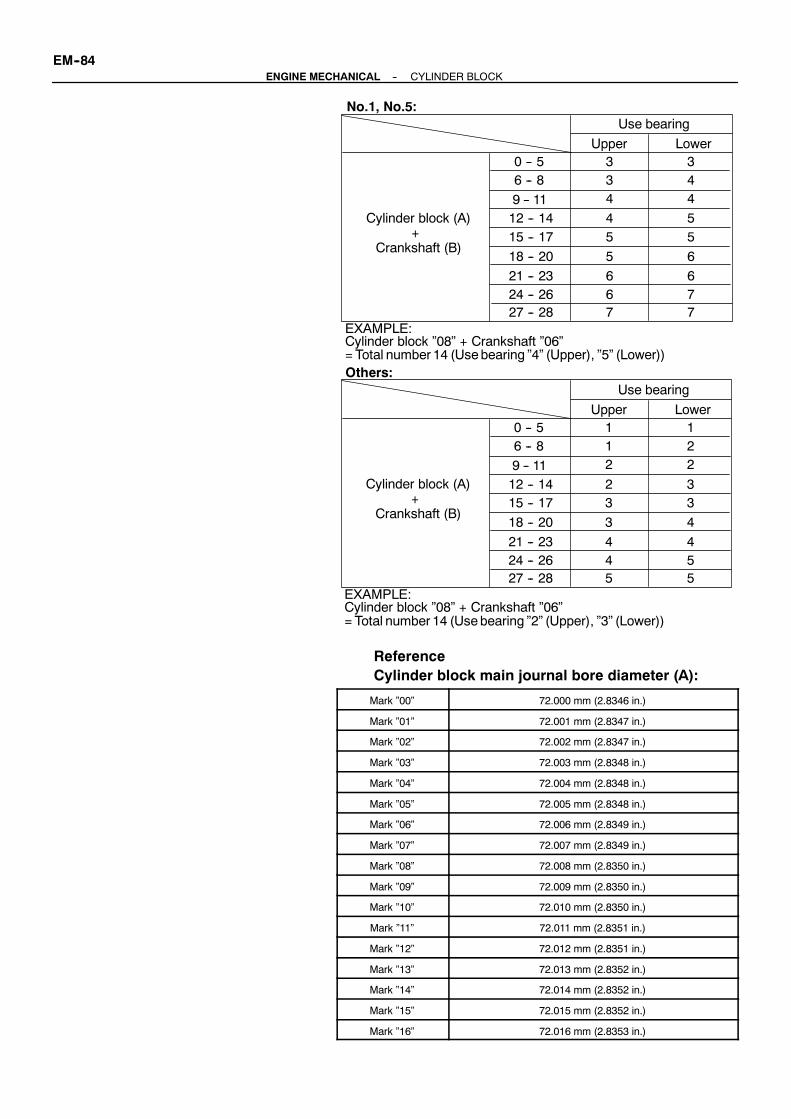
Cylinder block (A)
Crankshaft (B)
27 -- 28
Upper
Use bearing
Lower
+
24 -- 2621 -- 23
18 -- 20
15 -- 1712 -- 149 -- 11
6 -- 80 -- 5
No.1, No.5:
EXAMPLE:Cylinder block ”08” + Crankshaft ”06”= Total number 14 (Usebearing ”4” (Upper), ”5” (Lower))
3 334
45
5
66
7 776
6
55
44
Cylinder block (A)
Crankshaft (B)
27 -- 28
Upper
Use bearing
Lower
+
24 -- 2621 -- 23
18 -- 20
15 -- 1712 -- 149 -- 11
6 -- 80 -- 5
Others:
EXAMPLE:Cylinder block ”08” + Crankshaft ”06”= Total number 14 (Usebearing ”2” (Upper), ”3” (Lower))
1 112
23
3
44
5 554
4
33
22
EM--84--ENGINE MECHANICAL CYLINDER BLOCK
ReferenceCylinder block main journal bore diameter (A):
Mark ”00” 72.000 mm (2.8346 in.)
Mark ”01” 72.001 mm (2.8347 in.)
Mark ”02” 72.002 mm (2.8347 in.)
Mark ”03” 72.003 mm (2.8348 in.)
Mark ”04” 72.004 mm (2.8348 in.)
Mark ”05” 72.005 mm (2.8348 in.)
Mark ”06” 72.006 mm (2.8349 in.)
Mark ”07” 72.007 mm (2.8349 in.)
Mark ”08” 72.008 mm (2.8350 in.)
Mark ”09” 72.009 mm (2.8350 in.)
Mark ”10” 72.010 mm (2.8350 in.)
Mark ”11” 72.011 mm (2.8351 in.)
Mark ”12” 72.012 mm (2.8351 in.)
Mark ”13” 72.013 mm (2.8352 in.)
Mark ”14” 72.014 mm (2.8352 in.)
Mark ”15” 72.015 mm (2.8352 in.)
Mark ”16” 72.016 mm (2.8353 in.)

A01905
A01906
--ENGINE MECHANICAL CYLINDER BLOCKEM--85
Crankshaft main journal diameter (B):
Mark ”00” 67.000 mm (2.6378 in.)
Mark ”01” 66.999 mm (2.6378 in.)
Mark ”02” 66.998 mm (2.6377 in.)
Mark ”03” 66.997 mm (2.6377 in.)
Mark ”04” 66.996 mm (2.6376 in.)
Mark ”05” 66.995 mm (2.6376 in.)
Mark ”06” 66.994 mm (2.6376 in.)
Mark ”07” 66.993 mm (2.6375 in.)
Mark ”08” 66.992 mm (2.6375 in.)
Mark ”09” 66.991 mm (2.6374 in.)
Mark ”10” 66.990 mm (2.6374 in.)
Mark ”11” 66.989 mm (2.6374 in.)
Mark ”12” 66.988 mm (2.6373 in.)
Standard bearing center wall thickness:No.1 and No.5
Mark ”3” 2.492 -- 2.495 mm (0.0981 -- 0.0982 in.)
Mark ”4” 2.495 -- 2.498 mm (0.0982 -- 0.0983 in.)
Mark ”5” 2.498 -- 2.501 mm (0.0983 -- 0.0985 in.)
Mark ”6” 2.501 -- 2.504 mm (0.0985 -- 0.0986 in.)
Mark ”7” 2.504 -- 2.507 mm (0.0986 -- 0.0987 in.)
Others
Mark ”1” 2.486 -- 2.489 mm (0.0979 -- 0.0980 in.)
Mark ”2” 2.489 -- 2.492 mm (0.0980 -- 0.0981 in.)
Mark ”3” 2.492 -- 2.495 mm (0.0981 -- 0.0982 in.)
Mark ”4” 2.495 -- 2.498 mm (0.0982 -- 0.0983 in.)
Mark ”5” 2.498 -- 2.501 mm (0.0983 -- 0.0985 in.)
(l) Remove the 10 bolts, 20 nuts, 5 main bearing caps and5 lower main bearing.(See procedure (a) to (c) above)
(m) Remove the 5 upper main bearings from the cylinderblock.
HINT:Arrange the main bearing caps, bearings and thrust washers incorrect order.
25. CHECK FIT BETWEEN PISTON AND PISTON PINTry to move the piston back and forth on the piston pin.If any movement is felt, replace the piston and pin as a set.
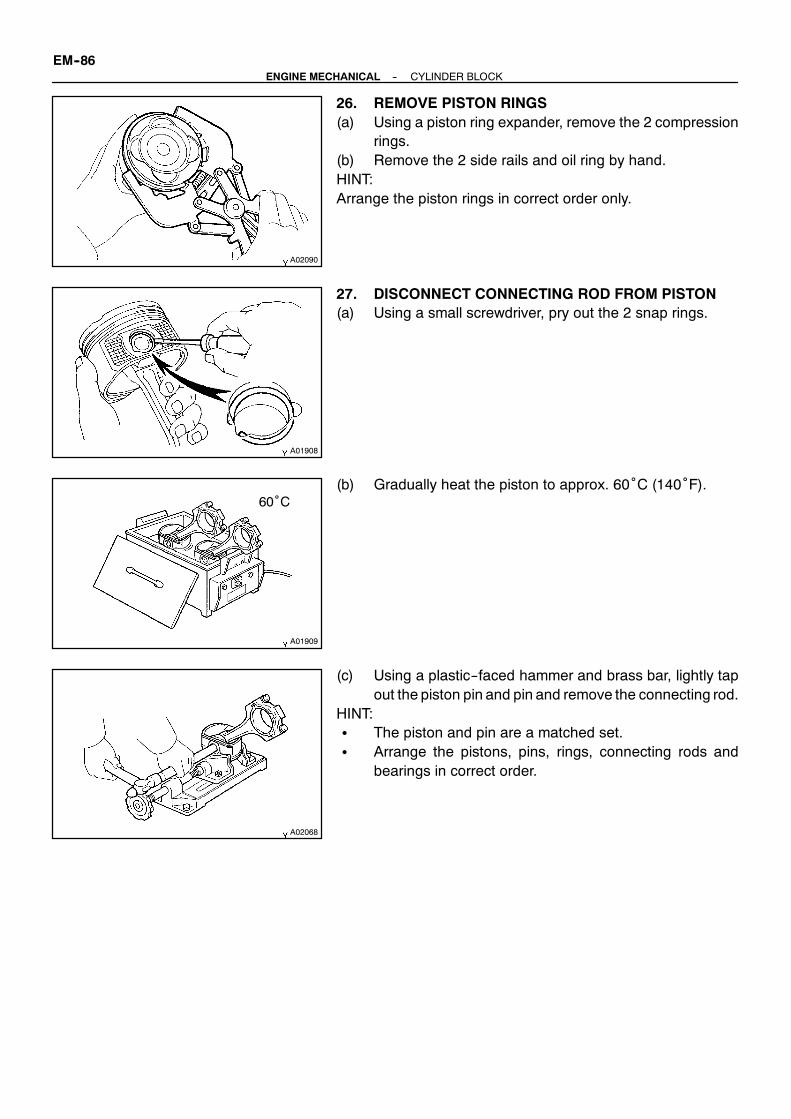
A02090
A01908
A01909
60˚C
A02068
EM--86--ENGINE MECHANICAL CYLINDER BLOCK
26. REMOVE PISTON RINGS(a) Using a piston ring expander, remove the 2 compression
rings.(b) Remove the 2 side rails and oil ring by hand.HINT:Arrange the piston rings in correct order only.
27. DISCONNECT CONNECTING ROD FROM PISTON(a) Using a small screwdriver, pry out the 2 snap rings.
(b) Gradually heat the piston to approx. 60˚C (140˚F).
(c) Using a plastic--faced hammer and brass bar, lightly tapout the piston pin and pin and remove the connecting rod.
HINT:S The piston and pin are a matched set.S Arrange the pistons, pins, rings, connecting rods and
bearings in correct order.

EM0GB--01
EM6413
Z04007
EM6414
A02069
: Mark 1, 2,or 3Front
No.2 No.4 No.6 No.8
No.1 No.3 No.5 No.7
--ENGINE MECHANICAL CYLINDER BLOCKEM--87
INSPECTION1. REMOVE GASKET MATERIALUsing a gasket scraper, remove all the gasket material from thetop surface of the cylinder block.2. CLEAN CYLINDER BLOCKUsing a soft brush and solvent, thoroughly clean the cylinderblock.NOTICE:If the cylinder is washed at high temperatures, the cylinderliner sticks out beyond the cylinder block, so always washthe cylinder block at a temperature of 45˚ or less.3. INSPECT TOP SURFACE OF CYLINDER BLOCK FOR
FLATNESSUsing a precision straight edge and feeler gauge, measure thesurface contacting the cylinder head gasket for warpage.
Maximum warpage:0.07 mm (0.0028 in.)
If warpage is greater thanmaximum, replace the cylinder block.
4. INSPECT CYLINDER FOR VERTICAL SCRATCHESVisually check the cylinder for vertical scratches.If deep scratches are present, replace the cylinder block.
5. INSPECT CYLINDER BORE DIAMETERHINT:There are 3 sizes of the standard cylinder bore diameter,marked ”1”, ”2” and ”3” accordingly. Themark is stamped on thetop of the cylinder block.
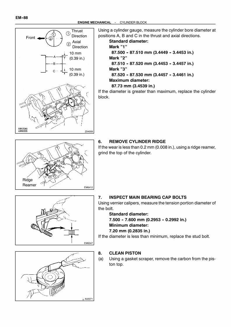
Z04009
12
1
2
B
C
A
ThrustDirection
AxialDirection
10 mm(0.39 in.)
10 mm(0.39 in.)
Front
EM6412
RidgeReamer
EM6347
A02071
EM--88--ENGINE MECHANICAL CYLINDER BLOCK
Using a cylinder gauge, measure the cylinder bore diameter atpositions A, B and C in the thrust and axial directions.
Standard diameter:Mark ”1”87.500 -- 87.510 mm (3.4449 -- 3.4453 in.)Mark ”2”87.510 -- 87.520 mm (3.4453 -- 3.4457 in.)Mark ”3”87.520 -- 87.530 mm (3.4457 -- 3.4461 in.)Maximum diameter:87.73 mm (3.4539 in.)
If the diameter is greater than maximum, replace the cylinderblock.
6. REMOVE CYLINDER RIDGEIf the wear is less than 0.2 mm (0.008 in.), using a ridge reamer,grind the top of the cylinder.
7. INSPECT MAIN BEARING CAP BOLTSUsing vernier calipers, measure the tension portion diameter ofthe bolt.
Standard diameter:7.500 -- 7.600 mm (0.2953 -- 0.2992 in.)Minimum diameter:7.20 mm (0.2835 in.)
If the diameter is less than minimum, replace the stud bolt.
8. CLEAN PISTON(a) Using a gasket scraper, remove the carbon from the pis-
ton top.

A02072
A02073
A02074
A02075 A02076
26.5 mm
LH Piston
RH Piston
Mark 1, 2, or 3
Mark 1, 2, or 3
--ENGINE MECHANICAL CYLINDER BLOCKEM--89
(b) Using a groove cleaning tool or broken ring, clean the pis-ton ring grooves.
(c) Using solvent and a brush, thoroughly clean the piston.NOTICE:Do not use a wire brush.
9. INSPECT PISTON OIL CLEARANCEHINT:There are 3 sizes of the standard piston diameter, marked ”1”,”2” and ”3” accordingly. The mark is stamped on the piston top.(a) Using a micrometer, measure the piston diameter at right
angles to the piston pin center line, 26.5 mm (1.04 in.)from the piston head.Piston diameter:Mark ”1”87.406 -- 87.416 mm (3.4411 -- 3.4416 in.)Mark ”2”87.416 -- 87.426 mm (3.4416 -- 3.4420 in.)Mark ”3”87.426 -- 87.436mm (3.4420 -- 3.4424 in.)
(b) Measure the cylinder bore diameter in the thrust direc-tions.(See step 5 above)
(c) Subtract the piston diametermeasurement from the cylin-der bore diameter measurement.Standard oil clearance:0.084 -- 0.104 mm (0.0033 -- 0.0041 in.)Maximum oil clearance:0.124 mm (0.0049 in.)
If the oil clearance is greater than maximum, replace all the 8pistons. If necessary, replace the cylinder block.

A02069
A02077 A02075 A02078
Cylinder Block
: Mark 1, 2,or 3Front
No.2 No.4 No.6 No.8
No.1 No.3 No.5 No.7
LH PistonRH PistonMark1, 2, or 3
Mark1, 2, or 3
A02079
A02081
105 mm
EM7639
EM--90--ENGINE MECHANICAL CYLINDER BLOCK
HINTUse new cylinder block:S Use a piston with the same number mark as the cylinder
diameter marked on the cylinder block.S The shape of the piston varies for the RH and LH banks.
The RH piston is marked with ”R”, the LH piston with ”L”.
10. INSPECT PISTON RING GROOVE CLEARANCEUsing a feeler gauge, measure the clearance between newpis-ton ring and the wall of the ring groove.
Ring groove clearance:No.10.020 -- 0.070 mm (0.0008 -- 0.0028 in.)No.20.010 -- 0.050 mm (0.0004 -- 0.0020 in.)
If the clearance is not as specified, replace the piston.
11. INSPECT PISTON RING END GAP(a) Insert the piston ring into the cylinder bore.(b) Using a piston, push the piston ring a little beyond the bot-
tomof the ring travel, 105 mm (4.13 in.) from the top of thecylinder block.
(c) Using a feeler gauge, measure the end gap.Standard end gap:No.10.250 -- 0.450 mm (0.0098 -- 0.0177 in.)No.20.500 -- 0.700 mm (0.0197 -- 0.0276 in.)Oil (Side rail)0.150 -- 0.500 mm (0.0059 -- 0.0197 in.)Maximum end gap:No.11.05 mm (0.0413 in.)No.21.30 mm (0.0512 in.)Oil (Side rail)1.10 mm (0.0433 in.)

A02080
60˚C
Z14454
Z14455
EM6525
EM0227
--ENGINE MECHANICAL CYLINDER BLOCKEM--91
If the end gap is greater than maximum, replace the piston ring.If the end gap is greater than maximum, even with a new pistonring, replace the cylinder block.12. INSPECT PISTON PIN FITAt 60˚C (140˚F), you should be able to push the piston pin intothe piston pin hole with your thumb.
13. INSPECT CONNECTING ROD ALIGNMENTUsing a rod aligner and feeler gauge, check the connecting rodalignment.
S Check for bend.Maximum bend:0.05 mm (0.0020 in.) per 100 mm (3.94 in.)
If bend is greater thanmaximum, replace the connecting rodas-sembly.
S Check for twistMaximum twist:0.15 mm (0.0059 in.) per 100 mm (3.94 in.)
If twist is greater than maximum, replace the connecting rod as-sembly.
14. INSPECT PISTON PIN OIL CLEARANCE(a) Using a caliper gauge,measure the inside diameter of the
connecting rod bushing.Bushing inside diameter:22.005 -- 22.014 mm (0.8663 -- 0.8667 in.)
(b) Using a micrometer, measure the piston pin diameter.Piston pin diameter:21.997 -- 22.006 mm (0.8660 -- 0.8664 in.)
(c) Subtract the piston pin diameter measurement from thebushing inside diameter measurement.Standard oil clearance:0.005 -- 0.011 mm (0.0002 -- 0.0004 in.)Maximum oil clearance:0.05 mm (0.0020 in.)

EM6347
P20662
Z14536
EM--92--ENGINE MECHANICAL CYLINDER BLOCK
If the oil clearance is greater than maximum, replace the bush-ing. If necessary, replace the piston and piston pin as a set.15. INSPECT CONNECTING ROD BOLTSUsing vernier calipers, measure the tension portion of the con-necting rod bolt.
Standard diameter:7.200 -- 7.300 mm (0.2835 -- 0.2874 in.)Minimum diameter:7.00 mm (0.2756 in.)
If the diameter is less than minimum, replace the bolt.16. INSPECT CRANKSHAFT FOR CIRCLE RUNOUT(a) Place the crankshaft on V--blocks.(b) Using a dial indicator, measure the circle runout at the
center journal.Maximum circle runout:0.08 mm (0.0031 in.)
If the circle runout is greater than maximum, replace the crank-shaft.
17. INSPECT MAIN JOURNALS AND CRANK PINS(a) Using a micrometer, measure the diameter of each main
journal and crank pin.Main journal diameter:66.988 -- 67.000 mm (2.6373 -- 2.6378 in.)Crank pin diameter:51.982 -- 52.000 mm (2.0465 -- 2.0472 in.)
If the diameter is not as specified, check the oil clearance (Seedisassembly). If necessary, replace the crankshaft.(b) Check eachmain journal and crank pin for taper and out--
of--round as shown.Maximum taper and out--of--round:0.02 mm (0.0008 in.)
If the taper and out--of--round is greater than maximum, replacethe crankshaft.

EM0GC--01
P20665
SST
P20666
OilHole
P20667
P20668
A04153
--ENGINE MECHANICAL CYLINDER BLOCKEM--93
REPLACEMENT1. REPLACE CONNECTING ROD BUSHINGS(a) Using SST and a press, press out the bushing.
SST 09222--30010
(b) Align the oil holes of a new bushing and the connectingrod.
(c) Using SST and a press, press in the bushing.SST 09222--30010
(d) Using a pin hole grinder, hone the bushing to obtain thestandard specified clearance (See page EM--87) be-tween the bushing and piston pin.
(e) Check the piston pin fit at normal room temperature. Coatthe piston pin with engine oil, and push it into the connect-ing rod with your thumb.
2. REPLACE CRANKSHAFT FRONT OIL SEALHINT:There are 2 methods ((a) and (b)) to replace the oil seal.(a) If oil pump is removed from cylinder block:
(1) Using a screwdriver, pry out the oil seal.

A04154
SST
Z06216
Cut Position
EG0059
SST
A02083
A02084
EM--94--ENGINE MECHANICAL CYLINDER BLOCK
(2) Using SST and a hammer, tap in a new oil seal untilits surface is flush with the oil pump body edge.
SST 09316--60011 (09316--00011)(3) Apply MP grease to the oil seal lip.
(b) If oil pump is installed to the cylinder block:(1) Using a knife, cut off the oil seal lip.(2) Using a screwdriver, pry out the oil seal.
NOTICE:Be careful not to damage the crankshaft. Tape the screw-driver tip.
(3) Apply MP grease to a new oil seal lip.(4) Using SST and a hammer, tap in the oil seal until its
surface is flush with the oil pump body edge.SST 09316--60011 (09316--00011)
3. REPLACE CRANKSHAFT REAR OIL SEALHINT:There are 2 methods ((a) and (b)) to replace the oil seal which.(a) If rear oil seal retainer is removed from cylinder block:
(1) Using a screwdriver and hammer, tap out the oilseal.
(2) Using SST and a hammer, tap in a new oil seal untilits surface is flush with the rear oil seal retaineredge.
SST 09223--56010(3) Apply MP grease to the oil seal lip.

M03107
Cut Position
M03108
SST
--ENGINE MECHANICAL CYLINDER BLOCKEM--95
(b) If rear oil seal retainer is installed to cylinder block:(1) Using a knife, cut off the oil seal lip.(2) Using a screwdriver, pry out the oil seal.
NOTICE:Be careful not to damage the crankshaft. Tape the screw-driver tip.
(3) Apply MP grease to a new oil seal lip.(4) Using SST and a hammer, tap in the oil seal until its
surface is flush with the rear oil seal retainer edge.SST 09223--56010

EM0GD--01
A02085
A02086
60˚C
A02087
A02088 A02089
Front Mark(2 Cavities)
Front Mark(1 Cavity)
Outside Mark
LH Piston
RH Piston
OutsideMark
A01908
EM--96--ENGINE MECHANICAL CYLINDER BLOCK
REASSEMBLYHINT:S Thoroughly clean all parts to be assembled.S Before installing the parts, apply new engine oil to all slid-
ing and rotating surfaces.S Replace all gaskets, O--rings and oil seals with newparts.1. ASSEMBLE PISTON AND CONNECTING ROD(a) Using a small screwdriver, install a new snap ring on one
side of the piston pin hole.
(b) Gradually heat the piston to about 60˚C (140˚F).
(c) Coat the piston pin with engine oil.(d) Position the piston front mark with respect to the outside
mark on the connecting rod as shown in the diagram.NOTICE:The installationdirections of the pistonandconnecting rodare different for the RH and LH banks. The RH piston ismarked with ”R”, the LH piston with ”L”.(e) Align the piston pin holes of the piston and connecting
rod, and push in the piston pin with your thumb.
(f) Using a small screwdriver, install a new snap ring on theother side of the piston pin hole.
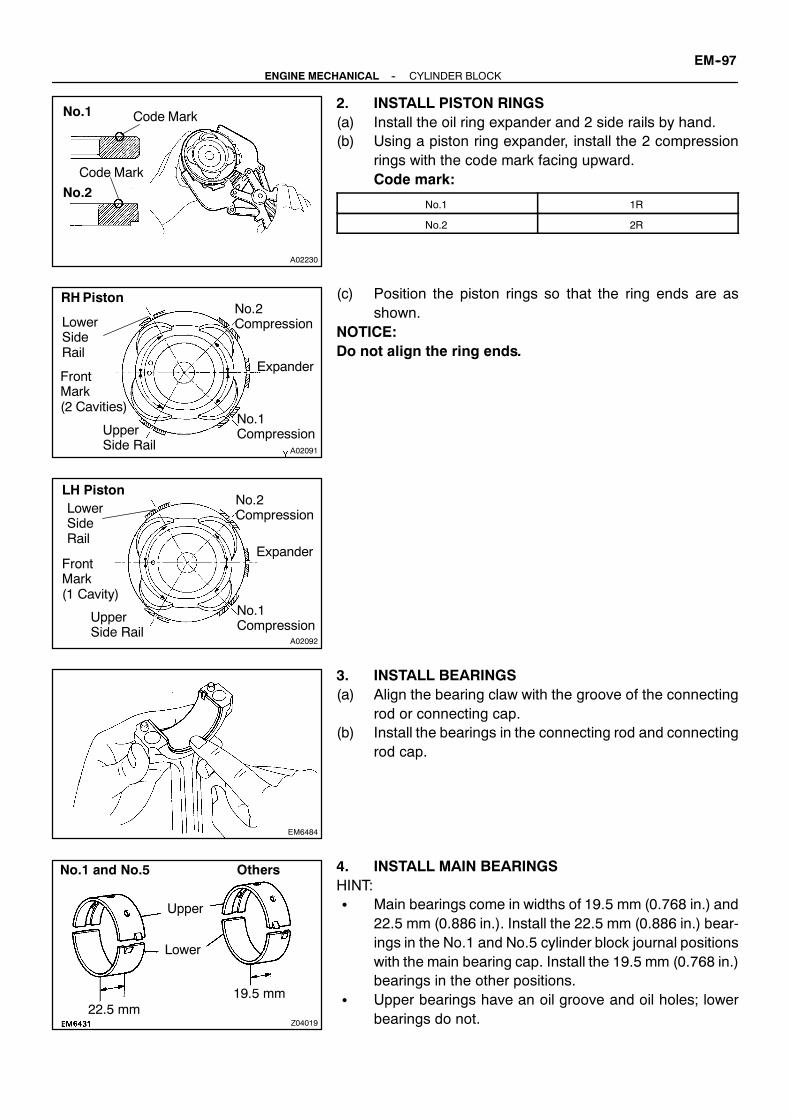
A02230
Code MarkNo.1
No.2
Code Mark
A02091
LowerSideRail
FrontMark(2 Cavities)
UpperSide Rail
No.1Compression
Expander
No.2Compression
RHPiston
A02092
LowerSideRail
FrontMark(1 Cavity)
UpperSide Rail
No.1Compression
Expander
LH PistonNo.2Compression
EM6484
Z04019
Upper
Lower
22.5 mm19.5 mm
No.1 and No.5 Others
--ENGINE MECHANICAL CYLINDER BLOCKEM--97
2. INSTALL PISTON RINGS(a) Install the oil ring expander and 2 side rails by hand.(b) Using a piston ring expander, install the 2 compression
rings with the code mark facing upward.Code mark:
No.1 1R
No.2 2R
(c) Position the piston rings so that the ring ends are asshown.
NOTICE:Do not align the ring ends.
3. INSTALL BEARINGS(a) Align the bearing claw with the groove of the connecting
rod or connecting cap.(b) Install the bearings in the connecting rod and connecting
rod cap.
4. INSTALL MAIN BEARINGSHINT:S Main bearings come in widths of 19.5 mm (0.768 in.) and
22.5 mm (0.886 in.). Install the 22.5 mm (0.886 in.) bear-ings in the No.1 and No.5 cylinder block journal positionswith the main bearing cap. Install the 19.5 mm (0.768 in.)bearings in the other positions.
S Upper bearings have an oil groove and oil holes; lowerbearings do not.

A02093
A02094
Mark1, 2, 3, 4, or 5
A02095
A02107
A02096
EM--98--ENGINE MECHANICAL CYLINDER BLOCK
(a) Align the bearing clawwith the claw groove of the cylinderblock, and push in the 5 upper bearings.
(b) Align the bearing claw with the claw groove of the mainbearing cap, and push in the 5 lower bearings.
HINT:A number is marked on each main bearing cap to indicate theinstallation position.
5. INSTALL UPPER THRUST WASHERSInstall the 2 thrust washers under the No.3 journal position ofthe cylinder block with the oil grooves facing outward.6. PLACE CRANKSHAFT ON CYLINDER BLOCK
7. PLACE MAIN BEARING CAPS AND LOWER THRUSTWASHERS ON CYLINDER BLOCK
(a) Install the 2 thrust washers on the No.3 bearing cap withthe grooves facing outward.
(b) Install the 5 main bearing caps in their proper locations.
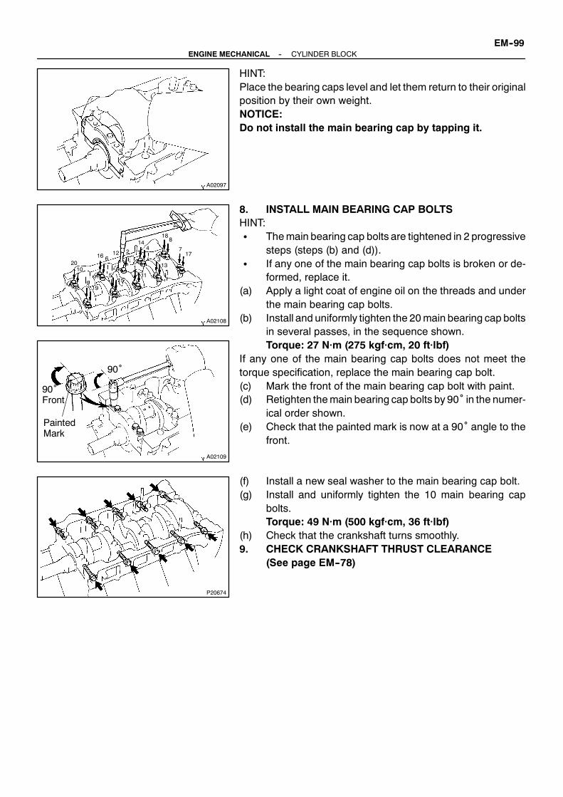
A02097
A02108
1
23
4
5
6
7
8
9
1011
12
13
14
15
16 17
18
19
20
A02109
90˚Front
PaintedMark
90˚
P20674
--ENGINE MECHANICAL CYLINDER BLOCKEM--99
HINT:Place the bearing caps level and let them return to their originalposition by their own weight.NOTICE:Do not install the main bearing cap by tapping it.
8. INSTALL MAIN BEARING CAP BOLTSHINT:S Themain bearing cap bolts are tightened in 2 progressive
steps (steps (b) and (d)).S If any one of the main bearing cap bolts is broken or de-
formed, replace it.(a) Apply a light coat of engine oil on the threads and under
the main bearing cap bolts.(b) Install and uniformly tighten the 20main bearing cap bolts
in several passes, in the sequence shown.Torque: 27 N·m (275 kgf·cm, 20 ft·lbf)
If any one of the main bearing cap bolts does not meet thetorque specification, replace the main bearing cap bolt.(c) Mark the front of the main bearing cap bolt with paint.(d) Retighten themain bearing cap bolts by 90˚ in the numer-
ical order shown.(e) Check that the painted mark is now at a 90˚ angle to the
front.
(f) Install a new seal washer to the main bearing cap bolt.(g) Install and uniformly tighten the 10 main bearing cap
bolts.Torque: 49 N·m (500 kgf·cm, 36 ft·lbf)
(h) Check that the crankshaft turns smoothly.9. CHECK CRANKSHAFT THRUST CLEARANCE
(See page EM--78)

EM6422A02098A02099 A02100
Front Mark(2 Cavities)
Front Mark(1 Cavity)
Front
PHPiston
LHPiston
Front
A02110
A02111A02112 A02113
Front
OutsideMark (Protrusion)
RH Bank
LH Bank
Outside Mark (Protrusion)
Front
EM--100--ENGINE MECHANICAL CYLINDER BLOCK
10. INSTALL PISTON AND CONNECTING RODASSEMBLES
Using a piston ring compressor, push the correctly numberedpiston and connecting rod assemblies into each cylinder withthe front mark of the piston facing forward.NOTICE:The shape of thepiston varies for theRHandLHbanks. TheRH piston is marked with ”R”, the LH piston with ”L”.
11. PLACE CONNECTING ROD CAP ON CONNECTINGROD
(a) Match the numbered connecting rod cap with the con-necting rod.
(b) Align the pin groove of the connecting rod cap with thepins of the connecting rod, and install the connecting rodcap.
(c) Check that the outside mark of the connecting rod cap isfacing in correct direction.

A02114
A02115
Front
90˚90˚
A02101
A
B
A
B
Seal Width2 -- 3 mm
A02102
NewO--Ring
--ENGINE MECHANICAL CYLINDER BLOCKEM--101
12. INSTALL CONNECTING ROD CAP BOLTSHINT:S The connecting rod cap bolts are tightened in 2 progres-
sive steps (steps (b) and (d)).S If any one of the connecting rod cap bolts is broken or de-
formed, replace it.(a) Apply a light coat of engine oil on the threads and under
the heads of the connecting rod cap bolts.(b) Install and alternately tighten the 2 connecting rod cap
bolts in several passes.Torque: 25 N·m (250 kgf·cm, 18 ft·lbf)
If any one of the connecting rod cap bolts does not meet thetorque specification, replace the connecting rod cap bolts.(c) Mark the front of the connecting cap bolt with paint.(d) Retighten the cap bolts 90˚ as shown.(e) Check that the painted mark is now at a 90˚ angle to the
front.(f) Check that the crankshaft turns smoothly.13. CHECK CONNECTING ROD THRUST CLEARANCE
(See page EM--78)14. INSTALL REAR OIL SEAL RETAINER(a) Remove any old packing (FIPG) material and be careful
not to drop any oil on the contact surfaces of the oil sealretainer and cylinder block.S Using a razor blade and gasket scraper, remove all
the oil packing (FIPG) material from the gasket sur-faces and sealing grooves.
S Thoroughly clean all components to remove all theloose material.
S Using a non--residue solvent, clean both sealingsurfaces.
(b) Apply seal packing to the oil seal retainer as shown in theillustration.Seal packing:Part No. 08826--00080 or equivalentS Install a nozzle that has been cut to a 2 -- 3mm(0.08
-- 0.12 in.) opening.S Parts must be assembled within 5 minutes of ap-
plication. Otherwise the material must be removedand reapplied.
S Immediately remove nozzle from the tube and rein-stall cap.
(c) Install a new O--ring to the cylinder block.(d) Install the oil seal retainer with the 7 bolts.
Torque: 8.0 N·m (80 kgf·cm, 71 in.·lbf)

P12477
Seal Packing
P20642
Front
Port
EM6687
A
B
Seal Width2 -- 3 mm
A
B
EM--102--ENGINE MECHANICAL CYLINDER BLOCK
15. INSTALL ENGINE COOLANT DRAIN UNIONS(a) Apply seal packing to 2 or 3 threads.
Seal packing:Part No. 08826--00100 or equivalent
(b) Install the RH and LH drain unions.Torque: 49 N·m (500 kgf·cm, 36 ft·lbf)
HINT:After applying the specified torque, rotate the drain union clock-wise until its drain port is facing forward.
16. INSTALL WATER SEAL PLATE(a) Remove any old packing (FIPG) material and be careful
not to drop any oil on the contact surfaces of the seal plateand cylinder block.S Using a razor blade and gasket scraper, remove all
the old packing (FIPG)material from the gasket sur-faces and sealing groove.
S Thoroughly clean all components to remove all theloose material.
S Using a non--residue solvent, clean both sealingsurfaces.
(b) Apply seal packing to the seal plate as shown in the il-lustration.Seal packing:Part No. 08826--00080 or equivalentS Install a nozzle that has been cut to a 2 -- 3mm(0.08
-- 0.12 in.) opening.S Parts must be assembled within 5 minutes of ap-
plication. Otherwise the material must be removedand reapplied.
S Immediately remove nozzle from the tube and rein-stall cap.
(c) Install the seal platewith the 2 nuts. Alternately tighten thenuts in several passes.Torque: 14 N·m (145 kgf·cm, 10 ft·lbf)
17. INSTALL OIL PUMP(See page LU--15)
18. INSTALL OIL STRAINER(See page LU--15)
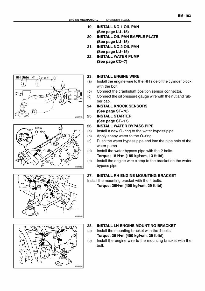
M00013
RH Side
M04152
Push NewO--ring
M04149
M04150
--ENGINE MECHANICAL CYLINDER BLOCKEM--103
19. INSTALL NO.1 OIL PAN(See page LU--15)
20. INSTALL OIL PAN BAFFLE PLATE(See page LU--15)
21. INSTALL NO.2 OIL PAN(See page LU--15)
22. INSTALL WATER PUMP(See page CO--7)
23. INSTALL ENGINE WIRE(a) Install the engine wire to the RH side of the cylinder block
with the bolt.(b) Connect the crankshaft position sensor connector.(c) Connect the oil pressure gauge wire with the nut and rub-
ber cap.24. INSTALL KNOCK SENSORS
(See page SF--70)25. INSTALL STARTER
(See page ST--17)26. INSTALL WATER BYPASS PIPE(a) Install a new O--ring to the water bypass pipe.(b) Apply soapy water to the O--ring.(c) Push the water bypass pipe end into the pipe hole of the
water pump.(d) Install the water bypass pipe with the 2 bolts.
Torque: 18 N·m (185 kgf·cm, 13 ft·lbf)(e) Install the engine wire clamp to the bracket on the water
bypass pipe.
27. INSTALL RH ENGINE MOUNTING BRACKETInstall the mounting bracket with the 4 bolts.
Torque: 39N·m (400 kgf·cm, 29 ft·lbf)
28. INSTALL LH ENGINE MOUNTING BRACKET(a) Install the mounting bracket with the 4 bolts.
Torque: 39 N·m (400 kgf·cm, 29 ft·lbf)(b) Install the engine wire to the mounting bracket with the
bolt.

EM--104--ENGINE MECHANICAL CYLINDER BLOCK
29. INSTALL FUEL PUMP(See page SF--9)
30. INSTALL CYLINDER HEADS(See page EM--52)
31. INSTALL TIMING BELT AND PULLEYS(See page EM--19)
32. DISCONNECT ENGINE FROM ENGINE STAND

ENGINE MECHANICAL
COMPRESSION EM--1. . . . . . . . . . . . . . . . . . . . . . . . .
VALVE CLEARANCE EM--2. . . . . . . . . . . . . . . . . . . . .
IGNITION TIMING EM--7. . . . . . . . . . . . . . . . . . . . . . .
IDLE SPEED EM--8. . . . . . . . . . . . . . . . . . . . . . . . . . . .
TIMING BELT EM--9. . . . . . . . . . . . . . . . . . . . . . . . . . . .
CYLINDER HEAD EM--24. . . . . . . . . . . . . . . . . . . . . . . .
ENGINE UNIT EM--67. . . . . . . . . . . . . . . . . . . . . . . . . . .
CYLINDER BLOCK EM--76. . . . . . . . . . . . . . . . . . . . . . .

EC05X--01
--EMISSION CONTROL EMISSION CONTROL SYSTEMEC--1
EMISSION CONTROL SYSTEMPURPOSEThe emission control systems are installed to reduce the amount of HC exhausted from the engine (2), toprevent the atmospheric release of blow--by gas--containing HC (1).The function of each system is shown in the following table:
System Abbreviation Function
(1) Positive Crankcase Ventilation
(2) Sequential Multiport Fuel Injection*
PCV
SFI
Reduces HC
Injects a precisely timed, optimum amount of fuel for reduced exhaust
emissions
Remark: * For inspection and repair of the SFI system, refer to the SF section in this manual.

B01745
Clean Hose
Cylinder HeadSide
B01746
IntakeManifoldSide
Clean Hose
EC060--01
B01747
EC--2 --EMISSION CONTROL POSITIVE CRANKCASE VENTILATION (PCV)SYSTEM
POSITIVE CRANKCASEVENTILATION (PCV) SYSTEMINSPECTION1. REMOVE PCV VALVE2. INSTALL CLEAN HOSE TO PCV VALVE3. INSPECT PCV VALVE OPERATION(a) Blow air into the cylinder head side, and check that air
passes through easily.CAUTION:Do not suck air through the valve.Petroleum substances inside the valve are harmful.(b) Blow air into the air intake chamber side, and check that
air passes through with difficulty.If operation is not as specified, replace the PCV valve.4. REMOVE CLEAN HOSE FROM PCV VALVE5. REINSTALL PCV VALVE
6. VISUALLY INSPECT HOSE, CONNECTIONS ANDGASKETS
Check for cracks, leaks or damage.

EMISSION CONTROL
EMISSION CONTROL SYSTEM EC--1. . . . . . . . . . .
POSITIVE CRANKCASE VENTILATION (PCV)
SYSTEM EC--2. . . . . . . . . . . . . . . . . . . . . . . . . . . . . .

SF0RO--01
--SFI SFI SYSTEMSF--1
SFI SYSTEMPRECAUTION1. BEFORE WORKING ON THE FUEL SYSTEM,
DISCONNECT THE NEGATIVE (--) TERMINAL CABLEFROM THE BATTERY
NOTICE:Any diagnostic trouble code retained by the computer willbe erased when the negative (--) terminal cable is removedfrom the battery.Therefore, if necessary, read the diagnosis before discon-necting the negative (--) terminal cable from the battery.2. DO NOT SMOKE OR WORK NEAR AN OPEN FLAME
WHEN WORKING ON THE FUEL SYSTEM3. KEEP GASOLINE AWAY FROM RUBBER OR
LEATHER PARTS4. MAINTENANCE PRECAUTIONS(a) In event of the engine misfire, following the precautions
should be taken.(1) Check proper connection of battery terminals, etc.(2) After repair work, check that the ignition coil termi-
nals and all other ignition system lines are recon-nected securely.
(3) When cleaning the engine compartment, be espe-cially careful to protect the electrical system fromwater.
5. IF BOAT IS EQUIPPED WITH MOBILE RADIOSYSTEM (HAM, CB, ETC.)
If the boat is equipped with a mobile communication system, re-fer to the precaution in the IN section.6. AIR INDUCTION SYSTEM(a) Separation of the engine oil dipstick, oil filler cap, PCV
hose, etc. may cause the engine to run out of tune.(b) Disconnection, looseness or cracks in the parts of the air
induction system between the throttle body and cylinderhead will allow air suction and cause the engine to run outof tune.
7. ELECTRONIC CONTROL SYSTEM(a) Before removing SFI wiring connectors, terminals, etc.,
first disconnect the power by either turning the ignitionswitch OFF or disconnecting the negative (--) terminalcable from the battery.
HINT:Always check the diagnostic trouble code before disconnectingthe negative (--) terminal cable from the battery.(b) When installing the battery, be especially careful not to in-
correctly connect the positive (+) and negative (--) cables.(c) Do not permit parts to receive a severe impact during re-
moval or installation. Handle all SFI parts carefully, espe-cially the ECM.

P03244
LockPress Down
P03245Lock
Insert
FI2553
SST
SF--2--SFI SFI SYSTEM
(d) Do not be careless during troubleshooting as there arenumerous transistor circuits and even slight terminal con-tact can further troubles.
(e) Do not open the ECM cover.
(f) When inspecting during rainy weather, take care to pre-vent entry of water. Also, when washing the enginecompartment, prevent water fromgetting on the SFI partsand wiring connectors.
(g) Parts should be replaced as an assembly.(h) Care is requiredwhen pulling out and inserting wiring con-
nectors.(i) Release the lock and pull out the connector, pulling on the
connectors.
(j) Fully insert the connector and check that it is locked.(k) When inspecting a connector with a volt/ohmmeter(l) Carefully take out the water--proofing rubber if it is a wa-
ter--proof type connector.(m) Insert the test probe into the connector from the wiring
side when checking the continuity, amperage or voltage.(n) Do not apply unnecessary force to the terminal.(o) After checking, install the water--proofing rubber on the
connector securely.
(p) Use SST for inspection or test of the injector or its wiringconnector.SST 09842--30070
8. FUEL SYSTEM(a) When disconnecting the high fuel pressure line, a large
amount of gasoline will spill out, so observe the followingprocedures:(1) Disconnect the fuel pump connector.(2) Start the engine. After the engine has stopped on
its own, turn the ignition switch OFF.

B01205
Delivery Pipe
O--RingGrommet
Injector
CORRECTWRONG
B01206
IntakeManifoldInsulator
Injector Spacer
Grommet
Delivery Pipe
O--Ring
O--Ring
M24637
TOYOTAHand--HeldTester
DLC 3
--SFI SFI SYSTEMSF--3
(3) Put a container under the connection.(4) Disconnect the connection.(5) Plug the connection with a rubber plug.(6) Reconnect the fuel pump connector.
(b) Connect the high pressure line.
(c) Observe these precautions when removing and installingthe injectors.(1) Never reuse the O--ring.(2) When placing a new O--ring on the injector, take
care not to damage it in any way.(3) Coat a new O--ring with spindle oil or gasoline be-
fore installing--never use engine, gear or brake oil.
(d) Install the injector to the delivery pipe and intakemanifoldas shown in the illustration.Before installing the injector must apply spindle oil or gas-oline on the place where a delivery pipe or an intakeman-ifold touches an O--ring of the injector.
(e) Check that there are no fuel leaks after doing mainte-nance anywhere on the fuel system.(1) Connect a TOYOTA hand--held tester to the DLC3.(2) Turn the ignition switch ON, and push the TOYOTA
hand--held tester main switch ON.NOTICE:Do not start the engine.
(3) Select the active test mode on the TOYOTA hand--held tester.
(4) Please refer to the TOYOTAhand--held tester oper-ator’s manual for further details.
(5) If you have no TOYOTA hand--held tester, connectthe positive (+) and negative (--) leads from the bat-tery to the fuel pump connector.(See page SF--5)

M02886
SF--4--SFI SFI SYSTEM
(6) Check the button on the fuel pressure pulsationdamper rises.The pressure in the high pressure line will rise toapprox. 392 kPa (4 kgf/cm2, 57 psi). In this state,check to see that there are no leaks from any partof the fuel system.
HINT:When checking the fuel pressure pulsation damper, remove thecover on it.
(7) Turn the ignition switch OFF.(8) Disconnect the TOYOTA hand--held tester from the
DLC3.

M00014
+B
FP
SF0RP--01
M02886
M02887
Ohmmeter
--SFI FUEL PUMPSF--5
FUEL PUMPON--BOAT INSPECTION1. CHECK FUEL PUMP OPERATION(a) Remove the circuit opening relay.(b) Using the SST, connect terminal +B and terminal FP of
the relay box.SST 09843--18020
(c) Turn the ignition switch ON.NOTICE:S Do not start the engine.S These testsmust be done quickly (within 10 seconds)
to prevent the coil from burning out.
(d) Check that there is pressure in the fuel pressure pulsationdamper.
HINT:When checking the fuel pressure pulsation damper, remove thecover on it.If there is fuel pressure, you will hear the sound of fuel flowing.If there is no pressure, check these parts:
S Fusible linkS FusesS EFI main relayS Fuel pumpS Circuit opening relayS Fuel pump resistorS ECMS Wiring connections
(e) Turn the ignition switch OFF.(f) Remove the SST from the relay box.(g) Install the circuit opening relay.
2. INSPECT FUEL PUMP RESISTANCEUsing an ohmmeter, measure the resistance between the ter-minals.
Resistance:0.5 -- 30 Ω at 20˚C (68˚F)
If the resistance is not as specified, replace the fuel pump and/or set plate.

M02889
GasketSST
FuelPipe
SST
M24637
TOYOTA Hand--Held Tester
DLC 3
SF--6--SFI FUEL PUMP
3. CHECK FUEL PRESSURE(a) Check the battery positive voltage is above 12 V.(b) Disconnect the negative (--) terminal cable from the bat-
tery.(c) Remove the RH fuel pressure pulsation damper
(See page SF--25).(d) Install the fuel inlet hose and SST (pressure gauge) to the
delivery pipe with 3 lower gaskets and the SST(union bolt).SST 09268--45014 (09268--41190, 90405--06167)Torque: 39 N·m (400 kgf·cm, 29 ft·lbf)
(e) Wipe off any splattered gasoline.(f) Using the SST, connect terminal +B and terminal FP of
the relay box.(See step 1. (a) to (b) above)
(g) Reconnect the negative (--) terminal cable to the battery.(h) Turn the ignition switch ON.(i) Measure the fuel pressure.
Fuel pressure:304 -- 343 kPa (3.1 -- 3.5 kgf/cm2, 44 -- 50 psi)
If pressure is high, replace the fuel pressure regulator.If pressure is low, check these parts:
S Fuel hoses and connectionsS Fuel pumpS Fuel filterS Fuel pressure regulator
(j) Remove the SST from the relay box.(See Step 1. (f) to (g) above.)
(k) Start the engine.(l) Measure the fuel pressure at idle.
Fuel pressure:304 -- 343 kPa (3.1 -- 3.5 kgf/cm2, 44 -- 50 psi)
If pressure is not as specified, check the fuel pressure regulator.(m) Stop the engine.(n) Check that the fuel pressure remains as specified for 5
minutes after the engine has stopped.Fuel pressure:147 kPa (1.5 kgf/cm2, 21 psi) or more
If pressure is not as specified, check the fuel pump, pressureregulator and/or injectors.(o) After checking fuel pressure, disconnect the negative (--)
terminal cable from the battery and carefully remove theSST to prevent gasoline from splashing.SST 09268--45014
(p) Reinstall the fuel pressure pulsation damper(See page SF--26).
(q) Reconnect the negative (--) terminal cable to the battery.(r) Check for fuel leaks.
(See page SF--1)

SF0RQ--01
M02546
z Gasket
zNon--reusable part
No.2 Fuel Inlet Hose
: Specified torqueN·m (kgf·cm, ft·lbf)
Fuel Inlet Pipe
z Gasket
Fuel Inlet Hose
Fuel PumpConnector
Fuel PumpConnector
Fuel PumpAssembly
7.0 (70, 60 in.·lbf)
27.5 (280, 20)
--SFI FUEL PUMPSF--7
COMPONENTS

SF0RR--01
M00015
M00016
M00017
SF--8--SFI FUEL PUMP
REMOVALCAUTION:Donot smoke or work near anopen flamewhenworkingonthe fuel pump.1. DISCONNECT FUEL PUMP CONNECTORS
2. DISCONNECT FUEL PIPE AND FUEL HOSE(a) Loosen the hose clamp and disconnect the fuel inlet
hose.(b) Remove the bolt and disconnect the fuel inlet pipe.(c) Loosen the hose clamp and disconnect the No. 2 fuel
hose.
3. REMOVE FUEL PUMP ASSYRmove the 6 bolts and remove the fuel pump assembly.

SF0RS--01
M00017
M00016
M00015
--SFI FUEL PUMPSF--9
INSTALLATION1. INSTALL FUEL PUMP ASSYInstall the fuel pump assembly to the fuel pump bracket with the6 bolts.
Torque: 7.0 N·m (70 kgf·cm, 60 in.·lbf)
2. CONNECT FUEL PIPE AND FUEL HOSE(a) Install the No. 2 fuel hose to the fuel pump and tighten the
hose clamp.Torque: 1.5 N.m (15 kgf.cm, 13 in.·lbf)
(b) Install the fuel inlet pipe to the fuel pump.Torque: 27.5 N.m (280 kgf.cm, 20 ft.lbf)
(c) Install the fuel inlet hose to the fuel pump and tighten thehose clamp.
3. CONNECT FUEL PUMP CONNECTOR

SF0RT--01
SF--10--SFI FUEL PRESSURE REGULATOR
FUEL PRESSURE REGULATORON--BOAT INSPECTIONINSPECT FUEL PRESSURE(See page SF--5)
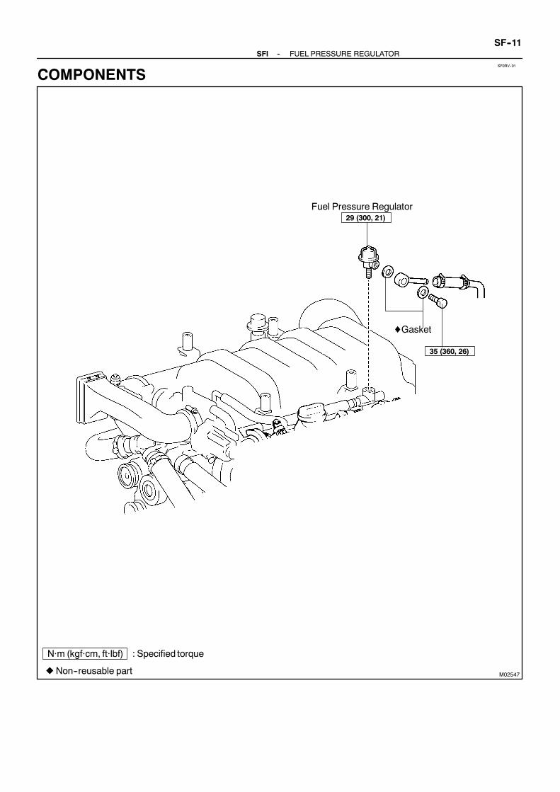
SF0RV--01
M02547
Fuel Pressure Regulator
zNon--reusable part
: Specified torqueN·m (kgf·cm, ft·lbf)
29 (300, 21)
♦Gasket
35 (360, 26)
--SFI FUEL PRESSURE REGULATORSF--11
COMPONENTS

SF0RW--01
M00018
M00019
SF--12--SFI FUEL PRESSURE REGULATOR
REMOVAL1. REMOVE V--BANK COVER2. REMOVE NO.4 FUEL HOSELoosen the hose clamp and disconnect theNo. 4 fuel hose fromthe fuel pipe.
3. REMOVE PRESSURE REGULATOR(a) Remove the union bolt, sub--pipe and 2 gaskets from the
pressure regulator.(b) Remove the LH delivery pipe from the pressure regulator.CAUTION:S Put a shop towel under the delivery pipe.S Slowly loosen the pressure regulator.

SF0RX--01
M00020
LH DeliveryPipe
M00021
M00018
--SFI FUEL PRESSURE REGULATORSF--13
INSTALLATION1. INSTALL PRESSURE REGULATOR(a) Install the pressure regulator to the LH delivery pipe in the
direction shown in the illustration at the left.Torque: 29 N·m (300 kgf·cm, 21 ft·lbf)
(b) Install the sub--pipe, 2 gaskets and the union bolt to thepressure regulator.Torque: 35 N·m (360 kgf·cm, 26 ft·lbf)
2. INSTALL NO. 4 FUEL HOSEInstall the No. 4 fuel hose to the fuel pipe and tighten the hoseclamp.
Torque: 1.5 N·m (15 kgf·cm, 13 in.·lbf)3. INSTALL V--BANK COVER

M03267
Ohmmeter
+--
SF0RY--01
SF--14--SFI INJECTOR
INJECTORON--BOAT INSPECTION1. REMOVE V--BANK COVER2. INSPECT INJECTOR RESISTANCE(a) Disconnect the 8 injector connectors.(b) Using a ohmmeter, measure the resistance between the
terminals.Resistance:13.4 -- 14.2 Ω at 20˚C (68˚F)
If the resistance is not as specified, replace the injector.(c) Reconnect the 8 injector connectors.3. REINSTALL V--BANK COVER
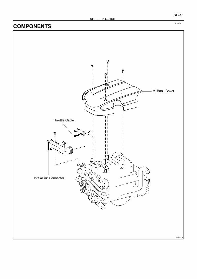
SF0RZ--01
M04118
V--Bank Cover
Throttle Cable
Intake Air Connector
--SFI INJECTORSF--15
COMPONENTS

M02894
zGasket
Fuel Pressure Pulsation Damper
Noise Filter Connector
Fuel Inlet Pipe
Fuel PressureRegulator
zGasket
zGasket
z Non--reusable part
Camshaft Timing Oil ControlValve Connector
Throttle Position Sensor Connector
ThrottleControl MotorConnector
Crankshaft PositionSensor ConnectorEngineWire
Accelerator PedalPosition SensorConnector
V--Bank Cover BracketV--Bank Cover Bracket
VVT Sensor 2Connector
Ignition CoilConnector
SF--16--SFI INJECTOR

M02895
Spacer
Delivery Pipe
SpacerDelivery Pipe
Spacer
Spacer
z Non--reusable part
Throttle ControlCable Bracket
VVT Sensor 1Connector
V--Bank CoverBracket
Injector(for 1, 2, 3 and4Cylinders)
z Insulator
zGrommet
z O--Ring InjectorConnector
z O--Ring
z O--Ring
z Insulator
Injector(for 5, 6, 7,and8Cylinders)
z O--Ring
zGrommet
Front Fuel Pipe
zGasket
zGasket
--SFI INJECTORSF--17

SF0S0--01
M00002
M00022
B02896
SF--18--SFI INJECTOR
REMOVAL1. REMOVE V--BANK COVER2. REMOVE INTAKE AIR CONNECTOR3. DISCONNECT THROTTLE CABLE4. REMOVE THROTTLE BODY
(See page SF--31)5. DISCONNECT ENGINE WIRE CONECTORSDisconnect these connectors:
S 8 injector connectorsS 2 VVT sensor connectorsS 2 camshaft position sensor connectorsS LH side noise filter connectorS LH side DLC--3 connectorS RH side ECT sensor connectorS RH side ECT sender gause connector
6. REMOVE DELIVERY PIPES AND INJECTORSNOTICE:S Be careful not to drop the injectors when removing
the delivery pipes.S Pay attention to put any hung load on the injector to
and from the side direction.(a) Remove these parts:
S Throttle control cable bracketS Oil drain hose clamp and spacerS Wiring harness clamp bracketS V--bank cover bracket w/noise filterS RH rear V--bank cover bracketS LH front V--bank cover bracketS Fuel pressure pulsation damper and fuel inlet pipeS No.4 fuel hose
(b) Remove the 2 union bolts, 4 gaskets, bolt and FR fuelpipe.
(c) Remove the 4 nuts holding the delivery pipe to the intakemanifold.
(d) Remove the 2 delivery pipes and 8 injectors assemblyand 4 spacers.
(e) Pull out the 8 injectors from the delivery pipes.(f) Remove the 2 O--rings, grommet and insulator from each
injector.

SF0S1--01
M01578
SST (Hose)
Injector
SST(Clamp)
B01576
SST (Union)
SST (Hose)
Injector SST(Clamp)
Vinyl Hose
M00014
+B
FP
B01577
Connect
SST(Wire)
B01671
--SFI INJECTORSF--19
INSPECTION1. INSPECT INJECTOR INJECTIONCAUTION:Keep injector clear of sparks during the test.(a) Disconnect the fuel inlet hose from the fuel tube.(b) Connect SST (hose) to the fuel inlet tube.
SST 09268--41047
(c) Install the grommet and O--ring to the injector.(d) Connect SST (hose) to the injector with SST (union), and
hold the injector and union with SST (clamp).SST 09268--41047
(e) Put the injector into the graduated cylinder.HINT:Install a suitable vinyl hose onto the injector to prevent gasolinefrom splashing out.
(f) Remove the circuit opening relay.(g) Using the SST, connect terminal +B and terminal FP of
the relay box.SST 09843--18020
(h) Turn the ignition switch ON.NOTICE:DO not start the engine.
(i) Connect SST (wire) to the injector and battery for 15 se-conds, and measure the injection volume with a gra-duated cylinder. Test each injector 2 or 3 times.SST 09842--30070Injection volume:60 -- 73 cm3 (3.7 -- 4.5 cu in.) per 15 sec.Difference between each injector:13 cm3 (0.6 cu in.) or less
If the injection volume is not as specified, replace the injector.
2. INSPECT LEAKAGE(a) In the condition above, disconnect the test probes of SST
(wire) from the battery and check the fuel leakage fromthe injector.SST 09842--30070Fuel drop:One drop or less per 12 minutes
(b) Turn the ignition switch OFF.

SF--20--SFI INJECTOR
(c) Disconnect the negative (--) terminal cable from the bat-tery.
(d) Remove SSTSST 09268--41047
(e) Reconnect the fuel inlet hose to the fuel tube.(f) Remove the SST from the relay box.
SST 09843--18020(g) Install the circuit opening relay.

SF0S2--01
B01220New Grommet
New Insulator
New O--Ring
New O--Ring
B01221Outward
ConnectorTurn
Push
B02899
B02896
B03461
Rotate
Outward
Connector
--SFI INJECTORSF--21
INSTALLATION1. INSTALL INJECTORS AND DELIVERY PIPESNOTICE:S Be careful not to drop the injectors when installing
the delivery pipes.S Pay attention to put any hung load on the injector to
and from the side direction.(a) Install a new grommet and new insulator to each injector.(b) Apply a light coat of gasoline to 2 newO--rings and install
them to each injector.(c) While turning the injector clockwise and counterclock-
wise, push it to the delivery pipes. Install the 8 injectors.(d) Position injector connector outward.
(e) Place the 4 spacers on the intake manifold.
(f) Place the 8 injectors and 2 delivery pipes assembly inposition on the intake manifold.
(g) Temporarily install the 4 nuts.
(h) Check that the injectors rotate smoothly.HINT:If injectors do not rotate smoothly, the probable cause is incor-rect installation of O--rings. Replace the O--rings.(i) Position injector connector outward.(j) Tighten the 4 nuts holding the delivery pipes to the intake
manifold.Torque: 18 N·m (185 kgf·cm, 13 ft·lbf)

M00023
M00002
M01673
M00024
A04483
SF--22--SFI INJECTOR
(k) Install the FR fuel pipe to the delivery pipewith the 2unionbolts and 4 gaskets.Torque: 39 N·m (400 kgf·cm, 29 ft·lbf)
(l) Install the fuel pipe and hoseS Fuel pressure pulsation damper and fuel inlet hoseTorque: 39 N·m (400 kgf·cm, 29 ft.·lbf)S No.4 fuel hoseTorque: 1.5 N·m (15 kgf·cm, 13 in.·lbf)
(m) Install these parts:S Throttle control cable bracketTorque: 18 N·m (185 kgf·cm, 13 ft.·lbf)
S Oil drain hose clamp and spacerTorque: 12 N·m (120 kgf·cm, 9 ft.·lbf)
S V--bank cover bracket w/noise filterTorque: 7.5 N·m (80 kgf·cm, 66 in.·lbf)

B01674
--SFI INJECTORSF--23
S RH rear V--bank cover bracketTorque: 7.5 N·m (80 kgf·cm, 66 in.·lbf)S LH front V--bank cover bracketTorque: 7.5 N·m (80 kgf·cm, 66 in.·lbf)
2. CONNECT ENGINE WIRE CONNECTORSConnect these connectors:
S 8 injector connectorsS 2 VVT sensor connectorsS 2 camshaft position sensor connectorsS LH side noise filter connectorS LH side DLC3 connectorS RH side ECT sensor connectorS RH side ECT sender gause connectorTorque: 2.5 N·m (25 kgf·cm, 22 in.·lbf)
3. INSTALL THROTTLE BODY(See page SF--41)
4. CONNECT THROTTLE CABLE5. INSTALL INTAKE AIR CONNECTOR6. INSTALL V--BANK COVER

SF0S3--01
M02893
V--Bank Cover
z Non--reusable part
Fuel Pressure Pulsation Damper
♦GasketFuel Inlet Pipe
♦Gasket
SF--24--SFI FUEL PRESSURE PULSATION DAMPER
FUEL PRESSURE PULSATION DAMPERCOMPONENTS

SF0S4--01
M02900
--SFI FUEL PRESSURE PULSATION DAMPERSF--25
REMOVAL1. REMOVE V--BANK COVER2. REMOVE FUEL PRESSURE PULSATION DAMPER(a) Remove pulsation damper and upper gasket.(b) Remove the fuel inlet pipe and lower gasket.CAUTION:S Put a shop towel under the delivery pipe.S Slowly loosen the pulsation damper.

SF0S5--01
M02902
FulcrumLength
SF--26--SFI FUEL PRESSURE PULSATION DAMPER
INSTALLATION1. INSTALL FUEL PRESSURE PULSATION DAMPERSUsing SST, install 2 new gaskets, the fuel inlet pipe and pulsa-tion damper. Install the 2 pulsation dampers.
SST 09612--24014 (09617--24011)Torque:39 N·m (400 kgf·cm, 29 ft·lbf)33 N·m (340 kgf·cm, 24 ft·lbf) for SST
HINT:Use a torque wrench with a fulcrum length of 30 cm (11.81 in.).2. CHECK FOR FUEL LEAKS
(See page SF--1)3. INSTALL V--BANK COVER
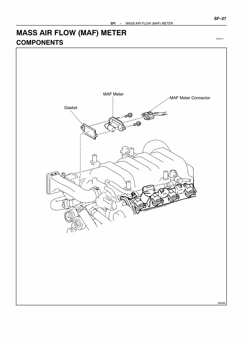
SF0SB--01
M2905
Gasket
MAF Meter ConnectorMAF Meter
--SFI MASS AIR FLOW (MAF) METERSF--27
MASS AIR FLOW (MAF) METERCOMPONENTS

SF0SD--01
M02906
SF--28--SFI MASS AIR FLOW (MAF) METER
REMOVALREMOVE MAF METER(a) Disconnect the MAF meter connector.(b) Remove the 2 bolts, MAF meter and gasket.

SF0SE--01
S04526
Ohmmeter
E2
THA
S04756
E2G
VG
AirVoltmeter
--SFI MASS AIR FLOW (MAF) METERSF--29
INSPECTION1. INSPECT MAF METER RESISTANCEUsing an ohmmeter,measure the resistance between terminalsTHA and E2.
Terminals Resistance Temperature
THA -- E2 13.6 -- 18.4 kΩ --20˚C (--4˚F)
THA -- E2 2.21 -- 2.69 kΩ 20˚C (68˚F)
THA -- E2 0.493 -- 0.667 kΩ 60˚C (140˚F)
If the resistance is not as specified, replace the MAF meter.2. INSPECT MAF METER OPERATION(a) Connect the MAF meter connector.(b) Turn the ignition switch ON.(c) Using a voltmeter, connect the positive (+) tester probe to
terminal VG, and negative (--) tester probe to terminalE2G.
(d) Blow air into the MAF meter, and check that the voltagefluctuates.
If operation is not as specified, replace the MAF meter.(e) Turn the ignition switch LOCK.(f) Disconnect the MAF meter connector.

SF0SF--01
SF--30--SFI MASS AIR FLOW (MAF) METER
INSTALLATIONInstallation is in the reverse order of removal.(See page SF--28)

M03462
SF0SG--01
B01725
M24637
TOYOTA Hand--Held Tester
DLC3
B01739
ECMVPA E2
Ohmmeter
--SFI THROTTLE BODYSF--31
THROTTLE BODYON--BOAT INSPECTION1. REMOVE V--BANK COVER2. INSPECT SYSTEM OPERATION(a) Check that the throttle linkage moves smoothly.
(b) Inspect the throttle control motor for operating sound.(1) Turn the ignition switch ON.(2) When turning the accelerator pedal position sensor
lever, check the running sound of the motor. Also,check that there is no friction sound.
If operation is not as specified, check the throttle control motor(See step 4), wiring and ECM.
(c) Inspect the accelerator pedal position sensor.(1) Connect the TOYOTA hand--held tester to the
DLC3.(2) Check that the MIL does not light up.(3) When turning the accelerator pedal position sensor
lever to the full--open position, check that thethrottle valve opening percentage (THROTTLEPOS) of the CURRENT DATA showns the standardvalue.
Standard throttle valve opening percentage:60 % or more
If operation is not as specified, check that the accelerator pedalposition sensor (See step 5), wiring and ECM.If you have no TOYOTA hand--held tester, measure voltage be-tween terminals VPA and E2 of the ECM connector.(d) Inspect the air assist system.
(1) Start the engine and check that the MIL does notlight up.
(2) Allow the engine to warm up to normal operatingtemperature.
(3) Turn the A/C conditioningON toOFF, and check theidle speed.
Idle speed (Transmission in neutral):700 ± 50 rpm
NOTICE:Perform inspectionunder conditionwithout electrical load.(e) After checking the above (b) to (d), perform the driving
test and check that there is no sense of incongruity.

B01726
Ohmmeter 3 4
1 2
B01727
Ohmmeter
VCE2
B01728
Ohmmeter
VC E2
SF--32--SFI THROTTLE BODY
3. INSPECT THROTTLE CONTROL MOTOR w/ CLUTCH(a) Disconnect the throttle control motor w/ clutch connector.(b) Using an ohmmeter, measure the motor resistance be-
tween terminal 1 (M+) and 2 (M--).Motor resistance:0.3 -- 100 Ω at 20˚C (68˚F)
If the resistance is not as specified, replace the throttle controlmotor w/ clutch. (See page SF--37)(c) Using an ohmmeter, measure the clutch resistance be-
tween terminal 3 (CL--) and 4 (CL+).Clutch resistance:4.2 -- 5.2 Ω at 20˚C (68˚F)
If the resistance is not as specified, replace the throttle controlmotor w/ clutch. (See page SF--37)(d) Reconnect the throttle control motor connector.
4. INSPECT THROTTLE POSITION SENSOR(a) Disconnect the throttle position sensor connector.(b) Using an ohmmeter, measure the resistance between ter-
minals VC and E2.Resistance:1.25 -- 2.35 kΩ at 20˚C (68˚F)
If the resistance is not as specified, replace the throttle positionsensor. (See page SF--37)(c) Reconnect the throttle position sensor connector.
5. INSPECT ACCELERATOR PEDAL POSITIONSENSOR
(a) Disconnect the accelerator position sensor connector.(b) Using an ohmmeter, measure the resistance between ter-
minals VC and E2.Resistance:1.64 -- 3.28 kΩ at 20˚C (68˚F)
If the resistance is not as specified, replace the accelerator ped-al position sensor. (See page SF--37)(c) Reconnect the accelerator pedal position sensor connec-
tor.6. REINSTALL V--BANK COVER

SF0SH--01
M04118
V--Bank Cover
Throttle Cable
Intake Air Connector
--SFI THROTTLE BODYSF--33
COMPONENTS

M02907
z Gasket
Water Inlet Housing Assembly
z Non--reusable part
Sea Water Hose
Accelerator Pedal PositionSensor Connector
Throttle Body
Water Bypass Hose
Throttle Control MotorConnector
Water Bypass Hose
Throttle Position SensorConnector
Sea Water Hose
SF--34--SFI THROTTLE BODY

B01729
Washer
Wave Washer
Throttle Control Motor Cover
Water Bypass Pipe w/ Hose
Throttle Control Motor w/ Clutch
Throttle Body
z Gasket
Drain Bolt
Accelerator Pedal Position Sensor
Throttle Position Sensor
Throttle PositionSensor Connector
--SFI THROTTLE BODYSF--35

SF0SI--01
B01214
(5)
(4)
(3)
(2)
(1)
SF--36--SFI THROTTLE BODY
REMOVAL1. REMOVE V--BANK COVER2. REMOVE INTAKE AIR CONNECTOR3. DISCONNECT THROTTLE CABLE FROM
THROTTLE BODY4. REMOVE WATER INLET HOUSING ASSEMBLY
(See page CO--5)5. REMOVE THROTTLE BODY(a) Disconnect these hoses and connectors from the throttle
body:(1) Accelerator pedal position sensor connector(2) Throttle position sensor connector(3) Throttle control motor connector(4) No.1 water bypass hose(5) No.7 water bypass hose
(b) Disconnect the 2 wire clamps from the throttle body.(c) Remove the 2 bolts, 2 nuts, throttle body and gasket.
Torque: 18 N·m (185 kgf·cm, 13 ft·lbf)HINT:At the time of installation, please refer to the following items.Use a new gasket.
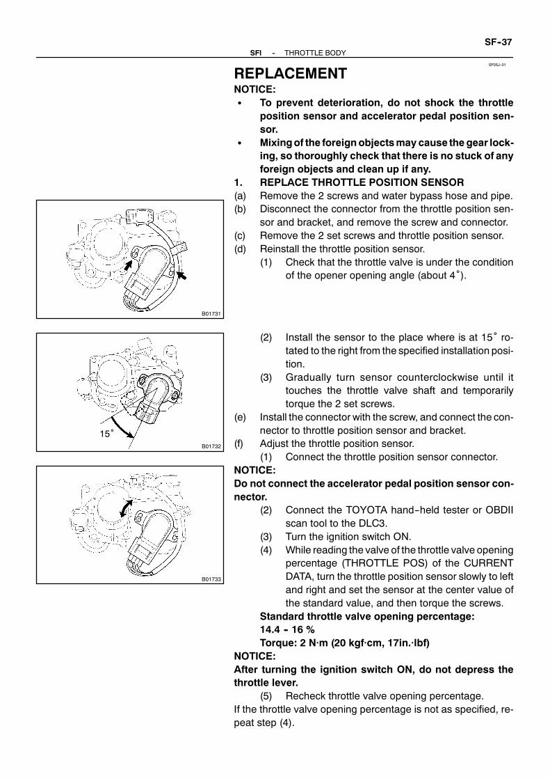
SF0SJ--01
B01731
B01732
15˚
B01733
--SFI THROTTLE BODYSF--37
REPLACEMENTNOTICE:S To prevent deterioration, do not shock the throttle
position sensor and accelerator pedal position sen-sor.
S Mixingof the foreignobjectsmay cause the gear lock-ing, so thoroughly check that there is no stuck of anyforeign objects and clean up if any.
1. REPLACE THROTTLE POSITION SENSOR(a) Remove the 2 screws and water bypass hose and pipe.(b) Disconnect the connector from the throttle position sen-
sor and bracket, and remove the screw and connector.(c) Remove the 2 set screws and throttle position sensor.(d) Reinstall the throttle position sensor.
(1) Check that the throttle valve is under the conditionof the opener opening angle (about 4˚).
(2) Install the sensor to the place where is at 15˚ ro-tated to the right from the specified installation posi-tion.
(3) Gradually turn sensor counterclockwise until ittouches the throttle valve shaft and temporarilytorque the 2 set screws.
(e) Install the connector with the screw, and connect the con-nector to throttle position sensor and bracket.
(f) Adjust the throttle position sensor.(1) Connect the throttle position sensor connector.
NOTICE:Do not connect the accelerator pedal position sensor con-nector.
(2) Connect the TOYOTA hand--held tester or OBDIIscan tool to the DLC3.
(3) Turn the ignition switch ON.(4) While reading the valve of the throttle valve opening
percentage (THROTTLE POS) of the CURRENTDATA, turn the throttle position sensor slowly to leftand right and set the sensor at the center value ofthe standard value, and then torque the screws.
Standard throttle valve opening percentage:14.4 -- 16 %Torque: 2 N·m (20 kgf·cm, 17in.·lbf)
NOTICE:After turning the ignition switch ON, do not depress thethrottle lever.
(5) Recheck throttle valve opening percentage.If the throttle valve opening percentage is not as specified, re-peat step (4).

B01735
B01736
B01737
SF--38--SFI THROTTLE BODY
(6) Perform fully closed throttle valve by hand andcheck that the valve of the throttle valve openingpercentage (THROTTLE POS) of the CURRENTDATA stays with the standard value.
Standard throttle valve opening percentage:10 -- 14 %
If the throttle valve opening percentage is not as specified, re-peat steps (4) to (6).
(7) Paint the sensor set screw.(8) Turn the ignition switch OFF.(9) Disconnect the TOYOTAhand--held tester orOBDII
scan tool from the DLC3.(10) Disconnect the throttle position sensor connector.
(g) Reinstall the water bypass hose and pipe with the 2screws.Torque: 5.4 N·m (55 kgf·cm, 47in.·lbf)
2. REPLACE THROTTLECONTROLMOTORw/CLUTCH(a) Remove the water bypass hose and pipe.(b) Remove the throttle position sensor.(c) Remove the throttle control motor w/ clutch.
(1) Disconnect the connector from the bracket.(2) Remove the 6 screws cover and motor assembly,
and washer.
(3) Remove the 3 screws, throttle control motor w/clutch and wave washer from the cover.
(d) Reinstall the throttle control motor w/ clutch.(1) Place the wave washer to the cover.(2) Match the holes of the positioning pin of the cover
and the motor, and then install the throttle controlmotor w/ clutch with the 3 set screws.
Torque: 3.4 N·m (35 kgf·cm, 30 in.·lbf)(3) Apply the grease thinly on the whole surface of the
gear teeth.

B01738
M01740
M01734
20˚
--SFI THROTTLE BODYSF--39
NOTICE:Do not apply the grease other than specified becausegrease has been already applied to the component to be re-placed.
(4) Place the washer as shown in the illustration.(5) Match the holes of the positioning pin of the throttle
body and the motor cover, and then install thethrottle control motor and cover assembly with the6 set screws.
Torque: 3.4 N·m (35 kgf·cm, 30 in.·lbf)(6) Connect the connector to the bracket.
(e) Reinstall and adjust the throttle position sensor. (See step1)
3. REPLACE ACCELERATOR PEDAL POSITIONSENSOR
(a) Remove the3 set screws andaccelerator position sensor.
(b) Reinstall the accelerator pedal position sensor.(1) Check that the throttle valve is under the condition
of the opener opening angle (about 4˚).(2) Install the sensor to the place where is at 20˚ ro-
tated to the left from the specified installation posi-tion.
(3) Gradually turn sensor clockwise until it touches thethrottle valve shaft and temporarily torque the 3 setscrews.
Torque: 5.4 N·m (55 kgf·cm, 47in.·lbf)(c) Inspect the accelerator pedal position sensor.
(1) Connect the accelerator pedal position sensor con-nector.
(2) Connect the TOYOTA hand--held tester or OBDIIscan tool to the DLC3.
(3) Turn the ignition switch ON.(4) Check that the ACCEL POS#1 (VPA) voltage of the
CURRENT DATA shows the standard value.Standard accelerator pedal position voltage:0.35 -- 0.85 V

SF--40--SFI THROTTLE BODY
NOTICE:After turning the ignition switch ON, do not depress the ac-celerator pedal.4. CHECK SYSTEM OPERATION
(See page SF--31)

SF0SK--01
--SFI THROTTLE BODYSF--41
INSTALLATIONInstallation is in the reverse order of removal.(See page SF--36)
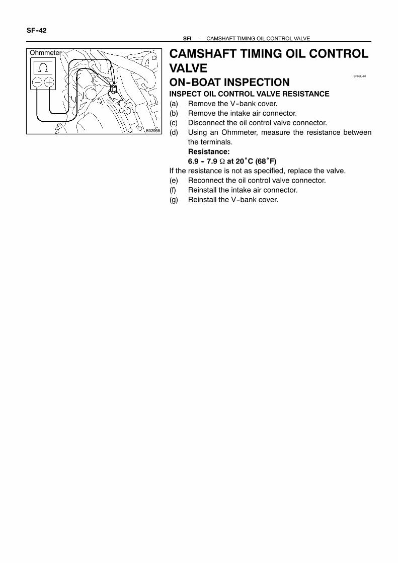
B02908
Ohmmeter
SF0SL--01
SF--42--SFI CAMSHAFT TIMING OIL CONTROL VALVE
CAMSHAFT TIMING OIL CONTROLVALVEON--BOAT INSPECTIONINSPECT OIL CONTROL VALVE RESISTANCE(a) Remove the V--bank cover.(b) Remove the intake air connector.(c) Disconnect the oil control valve connector.(d) Using an Ohmmeter, measure the resistance between
the terminals.Resistance:6.9 -- 7.9 Ω at 20˚C (68˚F)
If the resistance is not as specified, replace the valve.(e) Reconnect the oil control valve connector.(f) Reinstall the intake air connector.(g) Reinstall the V--bank cover.

SF0SM--01
M04118
V--Bank Cover
Throttle Cable
Intake Air Connector
--SFI CAMSHAFT TIMING OIL CONTROL VALVESF--43
COMPONENTS

B02909
Sea Water Hose
z Gasket
Throttle Control MotorConnector
ThrottlePositionSensorConnector
z Non--reusable part
z O--Ring z O--Ring
RH Camshaft TimingOil Control Valve
LH Camshaft TimingOil Control Valve
Water Inlet Housing Assembly
Accelerator Pedal PositionSensor Connector
Water Bypass Hose
Water Bypass Hose
Sea Water Hose
Throttle Body
SF--44--SFI CAMSHAFT TIMING OIL CONTROL VALVE

SF0SN--01
B01688
--SFI CAMSHAFT TIMING OIL CONTROL VALVESF--45
REMOVAL1. REMOVE V--BANK COVER2. REMOVE INTAKE AIR CONNECTOR3. DISCONNECT THROTTLE BODY FROM INTAKE
MANIFOLD(See page SF--53)
4. REMOVE CAMSHAFT TIMING OIL CONTROL VALVE(a) Disconnect the engine wire from thewire clamp on the LH
timing belt rear plate.(b) Disconnect the 2 camshaft oil control valve connectors.(c) Remove the bolt, camshaft oil control valve and O--ring.
Remove the 2 camshaft oil control valves.Torque: 7.5 N·m (80 kgf·cm, 66 in.·lbf)
(d) Remove the O--ring from the each camshaft oil controlvalve.
HINT:At the time of installation, please refer to the following items.Use a new O--rings.
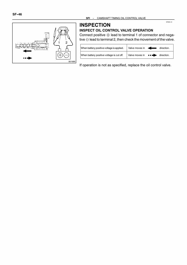
SF0SO--01
B01689
1 2
Whenbattery positive voltage is applied.
When battery positive voltage is cut off.
Valve moves in direction.
Valve moves in direction.
SF--46--SFI CAMSHAFT TIMING OIL CONTROL VALVE
INSPECTIONINSPECT OIL CONTROL VALVE OPERATIONConnect positive lead to terminal 1 of connector and nega-tive⊖ lead to terminal 2, then check themovement of the valve.
If operation is not as specified, replace the oil control valve.

SF0SP--01
--SFI CAMSHAFT TIMING OIL CONTROL VALVESF--47
INSTALLATIONInstallation is in the reverse order of removal.(See page SF--45)

M02910
Vacuum Gauge
SF0SQ--01
M02911
Pull
Approx. 39.9 kPa
SF--48--SFI ACOUSTIC CONTROL INDUCTION SYSTEM (ACIS)
ACOUSTIC CONTROL INDUCTIONSYSTEM (ACIS)ON--BOAT INSPECTIONINSPECT INTAKE AIR CONTROL VALVE(a) Remove V--bank cover.(b) Remove the intake air connector.(c) Disconnect the throttle body from the intake manifold.
(See page SF--53)(d) Remove the intake manifold.
(See page EM--29)(e) Using a 3--way connector, connect vacuum gauge to the
actuator hose.(f) Reinstall the intake manifold.(g) Reconnect the throttle body.(h) Start the engine.
(i) While the engine is idling, check that the vacuum gaugeneedle momentarily fluctuates up to approx. 39.9 kPa(300 mmHg, 11.8 in.Hg). (The actuator rod is pulled out.)
(j) Rapidly depress the accelerator pedal to fully open posi-tion and check that the vacuum gauge needle points to0 kPa (0 mmHg, 0 in.Hg). (The actuator rod is returned.)
(k) Disconnect the throttle body.(l) Remove the intake manifold.(m) Remove the vacuum gauge, and connect the vacuum
hose to the actuator.(n) Reinstall the intake manifold.(o) Reconnect the throttle body.(p) Reinstall the intake air connector.(q) Reinstall the V--bank cover.

SF0SR--01
M04118
V--Bank Cover
Throttle Cable
Intake Air Connector
--SFI ACOUSTIC CONTROL INDUCTION SYSTEM (ACIS)SF--49
COMPONENTS

Noise Filter ConnectorVSV Connectorfor ACISAccelerator Pedal
Position SensorConnector
zGasket
Throttle ControlMotor Connector
V--Bank CoverBracket V--Bank Cover Bracket
z Non--reusable part
Throttle PositionSensor Connector Injector Connector
zGasket
Throttle ControlCable Bracket
V--Bank Cover Bracket
Fuel Pressure Pulsation Damper
Engine Wire
VVT Sensor 2 Connector
Camshaft Position Sensor Connector
Ignition Coil Connector
Camshaft Timing OilControl Valve Connector
IntakeManifold Assembly
Fuel Inlet Pipe
Wiring Harness Clamp Bracket
zGasket
Fuel Hose
M02912
zGasket
SF--50--SFI ACOUSTIC CONTROL INDUCTION SYSTEM (ACIS)

M02913
x 13
z Non--reusable part
x 6
Intake Air Control Valve
VacuumHose
Actuator
z Gasket
Upper IntakeManifold
VSV Connector for ACIS
z Gasket
Lower IntakeManifold
--SFI ACOUSTIC CONTROL INDUCTION SYSTEM (ACIS)SF--51
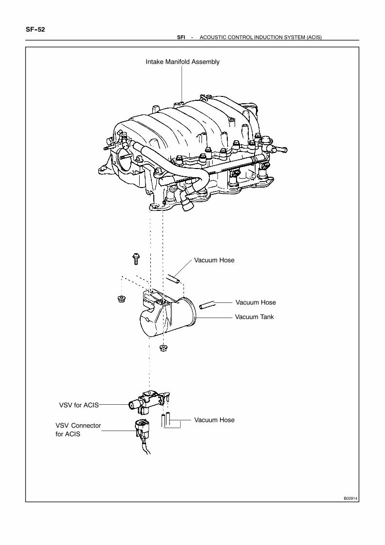
B02914
Vacuum Tank
Vacuum Hose
Vacuum Hose
VSV for ACIS
Vacuum HoseVSV Connectorfor ACIS
Intake Manifold Assembly
SF--52--SFI ACOUSTIC CONTROL INDUCTION SYSTEM (ACIS)

SF0SS--01
M01763
(1)(2)
(3)
(4)
M03135
B01691
M03137
--SFI ACOUSTIC CONTROL INDUCTION SYSTEM (ACIS)SF--53
REMOVAL1. REMOVE V--BANK COVER2. REMOVE INTAKE AIR CONNECTOR3. REMOVE WATER INLET HOUSING ASSEMBLY
(See page CO--5)4. DISCONNECT THROTTLE BODY FROM INTAKE
MANIFOLD(a) Disconnect the throttle cable.
(b) Disconnect these connectors and wire clamps:(1) Accelerator pedal position sensor connector(2) Throttle position sensor connector(3) Throttle control motor connector(4) Wire clamps
(c) Remove the 2 bolts and 2 nuts, and disconnect thethrottle body.
(d) Remove the gasket.5. REMOVE V--BANK COVER BRACKETS6. REMOVE INTAKE MANIFOLD ASSEMBLY
(See page EM--29)7. REMOVE ACTUATORRemove the 3 nuts, actuator and gasket.
8. REMOVE UPPER INTAKE MANIFOLD(a) Disconnect the vacuum hose from the actuator.
(b) Remove the bolt, and disconnect the VSV connector forACIS from the upper intake manifold.
(c) Remove the 3 nuts,15 bolts, upper intake manifold andgasket.
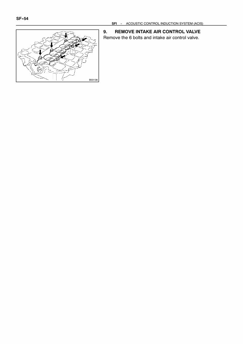
B03136
SF--54--SFI ACOUSTIC CONTROL INDUCTION SYSTEM (ACIS)
9. REMOVE INTAKE AIR CONTROL VALVERemove the 6 bolts and intake air control valve.

SF0ST--01
B01680
Vacuum
B03914
Air Air
B03915
Vacuum
--SFI ACOUSTIC CONTROL INDUCTION SYSTEM (ACIS)SF--55
INSPECTION1. INSPECT INTAKE AIR CONTROL VALVE(a) Install the air control valve and actuator to the upper in-
take manifold.(See page SF--56)
(b) With 39.9 kPa (300mmHg, 11.8 in.Hg) of vacuumappliedto the actuator, check that the actuator rod moves.
(c) One minute after applying the vacuum in (a), check thatthe actuator rod does not return.
If the operation is not as specified, replace the intake air controlvalve actuator.2. INSPECT VACUUM TANK(a) Remove the vacuum tank.(b) Check that air does not flow from port B to port A.(c) Check that air flows from port A to port B.
(d) Plug port B with your finger, and apply 39.9 kPa (300mmHg, 11.8 in.Hg) of vacuum to port A, and check thatthere is no change is vacuum after one minute.
If the operation is not as specified, replace the vacuum tank.(e) Reinstall the vacuum tank.3. INSPECT VSV
(See page SF--63)

SF0SU--01
B03136
M03137
A
A
B01691
M03135
SF--56--SFI ACOUSTIC CONTROL INDUCTION SYSTEM (ACIS)
INSTALLATION1. INSTALL INTAKE AIR CONTROL VALVEInstall the intake air control valve to the upper intake manifoldwith the 6 bolts.
Torque: 8.5 N·m (85 kgf·cm, 75 in.·lbf)
2. INSTALL UPPER INTAKE MANIFOLD(a) Place a new gasket on the lower intake manifold.(b) Install the upper intake manifold with the 3 nuts and 15
bolts.Torque: 18 N·m (185 kgf·cm, 13 ft·lbf)
HINT:Each bolt length is indicated in the illustration.Bolt length:30 mm (1.18 in.) for A20 mm (0.79 in.) for others(c) Connect the vacuum hose to the actuator.HINT:Pass the vacuum hose under the fuel pipe.(d) Connect the VSV connector for ACIS to the intake man-
ifold with the bolt.
3. INSTALL ACTUATOR(a) Place a new gasket to the upper intake manifold.(b) Install the actuator to the upper intake manifold with the
3 nuts.4. INSTALL INTAKE MANIFOLD ASSEMBLY
(See page EM--52)5. INSTALL V--BANK COVER BRACKETS
(See page EM--52)6. CONNECT THROTTLE BODY(a) Place the gasket to the intake manifold.(b) Connect the throttle body with the 2 bolts and 2 nuts.
Torque: 18 N·m (185 kgf·cm, 13 ft·lbf)

M01763
(1)(2)
(3)
(4)
--SFI ACOUSTIC CONTROL INDUCTION SYSTEM (ACIS)SF--57
(c) Connect these connectors and wire clamps:(1) Accelerator pedal position sensor connector(2) Throttle position sensor connector(3) Throttle control motor connector(4) Wire clamps
(d) Connect the accelerator cable.7. INSTALL WATER INLET HOUSING ASSEMBLY
(See page CO--7)8. CHECK FOR FUEL LEAKS
(See page SF--1)9. INSTALL INTAKE AIR CONNECTOR10. INSTALL V--BANK COVER

M03138
SF0SV--01
P05668
Continuity
2 1
NoContinuity
Ohmmeter Ohmmeter
34
P05667
Continuity
2 1
Ohmmeter
3Battery
4
SF--58--SFI EFI MAIN RELAY
EFI MAIN RELAYINSPECTION1. REMOVE EFI MAIN RELAY (Marking: EFI MAIN)LOCATION: Inside relay block at rear of engine.
2. INSPECT EFI MAIN RELAY CONTINUITY(a) Using an ohmmeter, check that there is continuity be-
tween terminals 1 and 3.If there is no continuity, replace the relay.(b) Check that there is no continuity between terminals 2 and
4.If there is continuity, replace the relay.
3. INSPECT EFI MAIN RELAY OPERATION(a) Apply battery voltage across terminals 1 and 3.(b) Using an ohmmeter, check that there is continuity be-
tween terminals 2 and 4.If there is no continuity, replace the relay.4. REINSTALL EFI MAIN RELAY

M01203
Circuit OpeningRelay
SF0SV--01
M07170
2
1
Continuity
Ohmmeter
Ohmmeter
64
NoContinuity
P05667
Continuity
2
1
Ohmmeter
4
Battery
6
--SFI CIRCUIT OPENING RELAYSF--59
CIRCUIT OPENING RELAYINSPECTION1. REMOVE CIRCUIT OPENING RELAY
(Marking: C/OPN)LOCATION: Inside relay block at rear of engine.
2. INSPECT CIRCUIT OPENING RELAY CONTINUITY(a) Using an ohmmeter, check that there is continuity be-
tween terminals 2 and 6.If there is no continuity, replace the relay.(b) Check that there is no continuity between terminals 1 and
4.If there is continuity, replace the relay.
3. INSPECT CIRCUIT OPENING RELAY OPERATION(a) Apply battery voltage across terminals 2 and 6.(b) Using an ohmmeter, check that there is continuity be-
tween terminals 1 and 4.If there is no continuity, replace the relay.4. REINSTALL CIRCUIT OPENING RELAY

SF0T1--01
M04118
V--Bank Cover
Throttle Cable
Intake Air Connector
SF--60 --SFI VSV FOR ACOUSTIC CONTROL INDUCTIONSYSTEM (ACIS)
VSV FOR ACOUSTIC CONTROL INDUCTION SYSTEM (ACIS)COMPONENTS

Noise Filter ConnectorVSV Connectorfor ACISAccelerator Pedal
Position SensorConnector
zGasket
Throttle ControlMotor Connector
V--Bank CoverBracket V--Bank Cover Bracket
z Non--reusable part
Throttle PositionSensor Connector Injector Connector
zGasket
Throttle ControlCable Bracket
V--Bank Cover Bracket
Fuel Pressure Pulsation Damper
Engine Wire
VVT Sensor 2 Connector
Camshaft Position Sensor Connector
Ignition Coil Connector
Camshaft Timing OilControl Valve Connector
IntakeManifold Assembly
Fuel Inlet Pipe
Wiring Harness Clamp Bracket
zGasket
Fuel Hose
M02912
zGasket
--SFI VSV FOR ACOUSTIC CONTROL INDUCTIONSYSTEM (ACIS)
SF--61

B02914
Vacuum Tank
Vacuum Hose
Vacuum Hose
VSV for ACIS
Vacuum HoseVSV Connectorfor ACIS
Intake Manifold Assembly
SF--62 --SFI VSV FOR ACOUSTIC CONTROL INDUCTIONSYSTEM (ACIS)

SF0T2--01
S04525
Continuity
Ohmmeter
S04524
No Continuity
Ohmmeter
FI6393
Air
E
Filter
--SFI VSV FOR ACOUSTIC CONTROL INDUCTIONSYSTEM (ACIS)
SF--63
INSPECTION1. REMOVE V--BANK COVER2. REMOVE INTAKE AIR CONNECTOR3. REMOVE WATER INLET HOUSING ASSEMBLY
(See page CO--5)4. DISCONNECT THROTTLE BODY
(See page SF--53)5. REMOVE INTAKE MANIFOLD ASSEMBLY
(See page EM--29)6. REMOVE VACUUM TANK7. REMOVE VSV(a) Disconnect the 2 vacuum hoses and connector from the
VSV.(b) Remove the screw and VSV.
8. INSPECT VSV FOR OPEN CIRCUITUsing an ohmmeter, check that there is continuity betweeneach terminals.
Resistance:33 -- 39 Ω at 20˚C (68˚F)
If there is no continuity, replace the VSV.
9. INSPECT VSV FOR GROUNDUsing an ohmmeter, check that there is no continuity betweeneach terminal and the body.If there is continuity, replace the VSV.
10. INSPECT VSV OPERATION(a) Check that air flows from port E to the filter
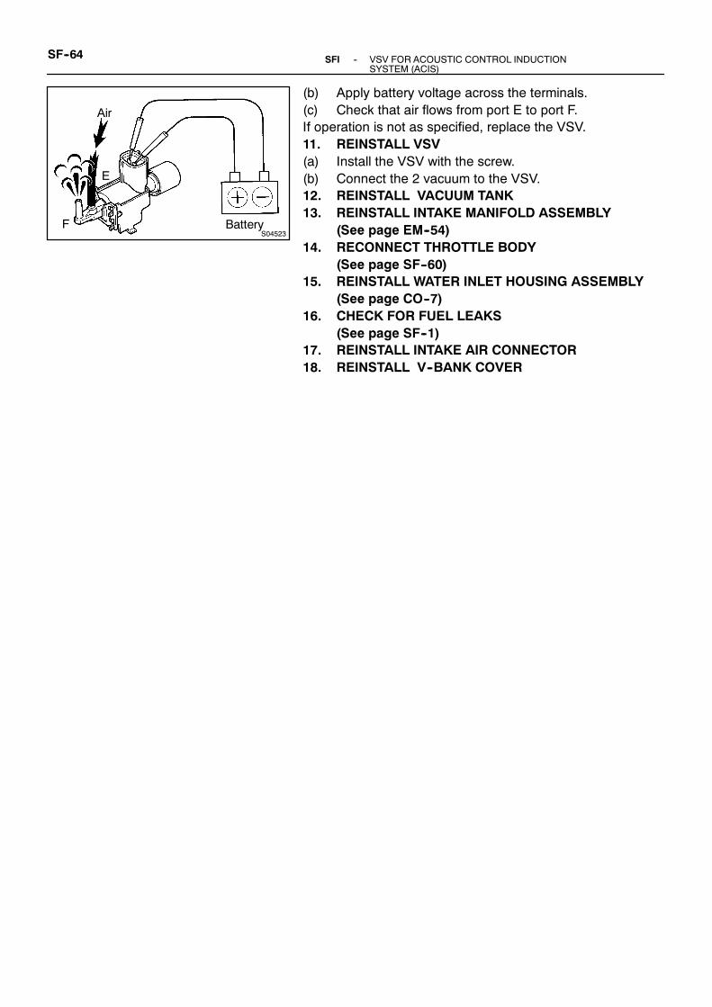
S04523
Air
E
F Battery
SF--64 --SFI VSV FOR ACOUSTIC CONTROL INDUCTIONSYSTEM (ACIS)
(b) Apply battery voltage across the terminals.(c) Check that air flows from port E to port F.If operation is not as specified, replace the VSV.11. REINSTALL VSV(a) Install the VSV with the screw.(b) Connect the 2 vacuum to the VSV.12. REINSTALL VACUUM TANK13. REINSTALL INTAKE MANIFOLD ASSEMBLY
(See page EM--54)14. RECONNECT THROTTLE BODY
(See page SF--60)15. REINSTALL WATER INLET HOUSING ASSEMBLY
(See page CO--7)16. CHECK FOR FUEL LEAKS
(See page SF--1)17. REINSTALL INTAKE AIR CONNECTOR18. REINSTALL V--BANK COVER

SF0T6--01
M04118
V--Bank Cover
Throttle Cable
Intake Air Connector
--SFI ENGINE COOLANT TEMPERATURE (ECT) SENSORSF--65
ENGINE COOLANT TEMPERATURE (ECT) SENSORCOMPONENTS

M03140
ThrottlePositionSensorConnector
Throttle Body
Water Inlet Housing Assembly
z Non--reusable part
Throttle Control MotorConnector
ECT Sensor
ECT Sensor Connector
z Gasket
Water Bypass Hose
Water Bypass Hose
Sea Water Hose
Sea Water Hose
Accelerator Pedal positionSensor Connector
SF--66--SFI ENGINE COOLANT TEMPERATURE (ECT) SENSOR

SF0T9--01
M03141
Z02917
Ohmmeter
Acceptable
RESISTA
NCEkΩ
TEMPERATURE ˚C (˚F)
--SFI ENGINE COOLANT TEMPERATURE (ECT) SENSORSF--67
INSPECTION1. REMOVE V--BANK COVER2. REMOVE INTAKE AIR CONNECTOR3. REMOVE WATER INLET HOUSING ASSEMBLY
(See page CO--5)4. DISCONNECT THROTTLE BODY
(See page SF--53)5. REMOVE ECT SENSOR(a) Disconnect the ECT sensor connector.(b) Remove the ECT sensor and gasket.6. INSPECT ECT SENSORUsing an ohmmeter, measure the resistance between the ter-minals.
Resistance:Refer to the chart graph
If the resistance is not as specified, replace the sensor.7. REINSTALL ECT SENSOR(a) Install a new gasket and the ECT sensor.
Torque: 20 N·m (200 kgf·cm, 14 ft·lbf)(b) Connect the ECT sensor connector.8. RECONNECT THROTTLE BODY
(See page SF--56)9. REINSTALL WATER INLET HOUSING ASSEMBLY
(See page CO--7)10. REINSTALL INTAKE AIR CONNECTOR11. REINSTALL V--BANK COVER

SF0TF--01
M04118
V--Bank Cover
Throttle Cable
Intake Air Connector
SF--68--SFI KNOCK SENSOR
KNOCK SENSORCOMPONENTS

M03146z Non--reusable part
Engine Wire
Camshaft Position Sensor Connector
NoiseFilter Connector
VSV Connectorfor ACIS
Accelerator PedalPosition SensorConnector
zGasket
Throttle ControlMotor Connector
Throttle PositionSensor Connector
Injector Connector
zGasket
Throttle ControlCable Bracket
V--Bank CoverBracket
V--Bank Cover BracketKnockSensor 1Connector
KnockSensor 1
Knock Sensor 2 Connector
KnockSensor 2
Camshaft Timing OilControl Valve Connector
VVTSensor 2Connector
Ignition Coil Connector
V--Bank Cover Bracket
Intake Manifold Assembly
Wiring Harness Clamp Bracket
Fuel Inlet Pipe
Fuel Pressure Pulsation Damper
Fuel Hose
zGasket
--SFI KNOCK SENSORSF--69

SF0TG--01
M03142SST
P01630
Ohmmeter
M03143SST
SF--70--SFI KNOCK SENSOR
INSPECTION1. REMOVE V--BANK COVER2. REMOVE INTAKE AIR CONNECTOR3. REMOVE WATER INLET HOUSING ASSEMBLY
(See page CO--5)4. DISCONNECT THROTTLE BODY
(See page SF--53)5. REMOVE INTAKE MANIFOLD ASSEMBLY
(See page EM--29)
6. REMOVE KNOCK SENSOR(a) Disconnect the knock sensor connectors.(b) Using SST, remove the 2 knock sensors.
SST 09816--30010
7. INSPECT KNOCK SENSORUsing an ohmmeter, check that there is no continuity betweenthe terminal and body.If there is continuity, replace the sensor.
8. REINSTALL KNOCK SENSOR(a) Using SST, install the 2 knock sensors.
SST 09816--30010Torque:44 N·m (450 kgf·cm, 33 ft·lbf)
(b) Connect the knock sensor connectors.9. REINSTALL INTAKE MANIFOLD ASSEMBLY
(See page EM--52)10. REINSTALL WATER INLET HOUSING ASSEMBLY
(See page CO--7)11. RECONNECT THROTTLE BODY
(See page SF--56)12. CHECK FOR FUEL LEAKS
(See page SF--1)13. REINSTALL INTAKE AIR CONNECTOR14. REINSTALL V--BANK COVER

SF0TL--01
M04118
V--Bank Cover
Throttle Cable
Intake Air Connector
--SFI VVT SENSOR
SF--71
VVT SENSORCOMPONENTS

M03147z Non--reusable part
Engine Wire
Camshaft Position Sensor Connector
Noise Filter ConnectorAccelerator PedalPosition SensorConnector
zGasket
Throttle ControlMotor Connector
Throttle PositionSensor Connector
Injector Connector
zGasket
Fuel Pressure Pulsation Damper
V--Bank Cover Bracket
V--Bank CoverBracket
V--Bank Cover Bracket
Camshaft Timing OilControl Valve Connector
Ignition Coil Connector
VVT Sensor 1Connector
VVT Sensor 2
VVT Sensor 2Connector
VVT Sensor 1
VSV Connectorfor ACIS
IntakeManifold Assembly
Wiring Harness Clamp Bracket
Fuel Inlet Pipe
Fuel Hose
Throttle ControlCable Bracket
zGasket
zGasket
SF--72--SFI VVT SENSOR

SF0TM--01
B01765
Ohmmeter
--SFI VVT SENSORSF--73
INSPECTIONNOTICE:”Cold” and ”Hot in these sentences express the tempera-ture of the sensors themselves. ”Cold” is from -- 10 ˚C(14˚F) to 50˚C (122˚F) and ”Hot” is from 50 ˚C (122˚F) to100˚C (212˚F).1. REMOVE V--BANK COVER
2. INSPECT VVT SENSOR RESISTANCE(a) Disconnect the VVT sensor connector.(b) Using a ohmmeter, measure the resistance between ter-
minals.Resistance:835 -- 1,400 Ω at cold1,060 -- 1,645 Ω at hot
If the resistance is not as specified, replace the sensor.(c) Reconnect the VVT sensor connector.(d) Connect the VVT sensor connector.3. REINSTALL V--BANK COVER

SF0TR--01
M02459
V--Bank Cover
Engine Control Computer Case
Engine Control Computer
Engine Control ComputerConnector
Wire HarnessBoot
Wiring HarnessClamp Bracket
SF--74--SFI ENGINE CONTROL MODULE(ECM)
ENGINE CONTROL MODULE (ECM)COMPONENTS

SF0TM--01
M00008
WireHarness Boot
--SFI ENGINE CONTROL MODULE(ECM)SF--75
INSPECTION1. REMOVE V--BANK COVER2. REMOVE ENGINE CONTROL COMPUTER CASE(a) Remove the wire harness boot from the engine control
computer case.(b) Disconnect the 5 connectors from theengine control com-
puter.(c) Remove the 4 bolts, then remove the engine control com-
puter case.3. REMOVE ECMRremove the 4 bolts and ECM.4. INSPECT ECM
(See page DI--18)5. REINSTALL ECMInstall the ECM with the 4 bolts.
Torque: 3 N·m (30 kgf·cm, 27 in.·lbf)6. INSTALL ENGINE CONTROL COMPUTER CASE(a) Install the engine control computer case to the engine
control computer bracket with the 4 bolts.Torque: 8 N·m (80 kgf·cm, 71 in.·lbf)
(b) Connect the 5 connectors to the engine computer.(c) Install the wire harness boot to the engine control comput-
er case.7. REINSTALL V--BANK COVER

SF0TT--01
M24637
DLC3
TOYOTA Hand--Held Tester
B03145
Sound Scope
SF--76--SFI FUEL CUT RPM
FUEL CUT RPMINSPECTION1. REMOVE V--BANK COVER2. WARM UP ENGINEAllow the engine to warm up to normal operating temperature.
3. CONNECT TOYOTA HAND--HELD TESTER OROBD II SCAN TOOL
(a) Connect the TOYOTA hand--held tester or OBD II scantool to the DLC3.
(b) Please refer to the TOYOTA hand--held tester or OBD IIscan tool operator’s manual for further details.
4. INSPECT FUEL CUT OPERATION(a) Increase the engine speed to at least 2,500 rpm.(b) Use a sound scope to check for injector operating noise.(c) Check that when the throttle lever is released, injector op-
eration noise stops momentarily and then resumes.HINT:S The boat should be stopped.
Fuel return rpm:1,400 rpm
5. DISCONNECT TOYOTA HAND--HELD TESTER OROBD II SCAN TOOL
6. REINSTALL V--BANK COVER

SFI
SFI SYSTEM SF--1. . . . . . . . . . . . . . . . . . . . . . . . . . . .
FUEL PUMP SF--5. . . . . . . . . . . . . . . . . . . . . . . . . . . . .
FUEL PRESSURE REGULATOR SF--10. . . . . . . . . . .
INJECTOR SF--14. . . . . . . . . . . . . . . . . . . . . . . . . . . . . .
FUEL PRESSURE PULSATION DAMPER SF--24. . .
MASS AIR FLOW (MAF) METER SF--27. . . . . . . . . .
THROTTLE BODY SF--31. . . . . . . . . . . . . . . . . . . . . . .
CAMSHAFT TIMING OIL CONTROL
VALVE SF--42. . . . . . . . . . . . . . . . . . . . . . . . . . . . . . . .
ACOUSTIC CONTROL INDUCTION
SYSTEM (ACIS) SF--48. . . . . . . . . . . . . . . . . . . . . . .
EFI MAIN RELAY SF--58. . . . . . . . . . . . . . . . . . . . . . . .
CIRCUIT OPENING RELAY SF--59. . . . . . . . . . . . . . .
VSV FOR ACOUSTIC CONTROL INDUCTION
SYSTEM (ACIS) SF--60. . . . . . . . . . . . . . . . . . . . . . .
ENGINE COOLANT TEMPERATURE (ECT)
SENSOR SF--65. . . . . . . . . . . . . . . . . . . . . . . . . . . . . .
KNOCK SENSOR SF--68. . . . . . . . . . . . . . . . . . . . . . . .
VVT SENSOR SF--71. . . . . . . . . . . . . . . . . . . . . . . . . . .
ENGINE CONTROL MODULE (ECM) SF--74. . . . . . .
FUEL CUT RPM SF--76. . . . . . . . . . . . . . . . . . . . . . . . .

CO0CM--01
M03269
V--Bank Cover
Intake Air Connector
--COOLING WATER PUMPCO--1
WATER PUMPCOMPONENTS

M04284
Water Bypass Hose
Camshaft PositionSensor Connector
Drive Belt Idler Pulley
Cover Plate
Gasket
RH No.3 TimingBelt Cover
No.2 TimingBelt Cover
Engine Wire
7.5 (80, 66 in.·lbf)
16 (160, 12)
39 (400, 29)
7.5 (80, 66 in.·lbf)
N·m (kgf·cm, ft·lbf) : Specified Torque
18 (185,13)
Water Inlet HousingAssembly
SeaWater Hose
Oil Cooler Pipe
LH No.3 TimingBelt Cover
Gasket
M03268N·m (kgf·cm, ft·lbf) : Specified torque
Sea Water Pump
Timing Belt
TimingBelt Tensioner
Camshaft Timing Pulley
Camshaft TimingPulley
16 (160, 12)
7.5 (80, 66 in.·lbf)
32 (330, 24)
245 (2,500, 181)
38 (390, 28)
Fan Bracket
CO--2--COOLING WATER PUMP

M03266
N·m (kgf·cm, ft·lbf) : Specified torqueLPrecoated part
Generator Wire
Generator Connector
Wire Clamp
Generator
Crankshaft Pulley
DriveBelt Tensioner
No.1 Timing Belt Cover
Timing Belt
Timing Belt Guide(Crankshaft Angle Sensor Plate)
No.2 Idler Pulley
TimingBelt Cover Spacer
Gasket
No.1 Idler Pulley
Crankshaft Timing Pulley
34.5 (350, 25)
34.5 (350, 25)
L
39 (400, 29)
Plate Washer
--COOLING WATER PUMPCO--3

M03031z Non--reusable part
Water Pump
Throttle PositionSensor Connector
Throttle Control MotorConnector
Throttle Body
z Gasket
Accelerator Pedal Position SensorConnector
Water Bypass Hose
z O--Ring
N·m (kgf·cm, ft·lbf) : Specified torque
18 (185, 13)
18 (185, 13)
21 (215, 15)
18 (185, 13)
CO--4--COOLING WATER PUMP
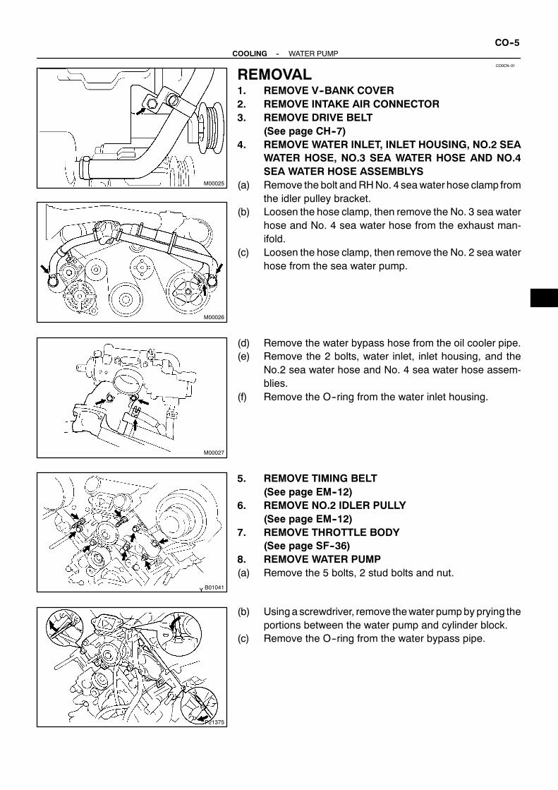
CO0CN--01
M00025
M00026
M00027
B01041
P21375
--COOLING WATER PUMPCO--5
REMOVAL1. REMOVE V--BANK COVER2. REMOVE INTAKE AIR CONNECTOR3. REMOVE DRIVE BELT
(See page CH--7)4. REMOVE WATER INLET, INLET HOUSING, NO.2 SEA
WATER HOSE, NO.3 SEA WATER HOSE AND NO.4SEA WATER HOSE ASSEMBLYS
(a) Remove the bolt andRHNo. 4 seawaterhose clamp fromthe idler pulley bracket.
(b) Loosen the hose clamp, then remove the No. 3 sea waterhose and No. 4 sea water hose from the exhaust man-ifold.
(c) Loosen the hose clamp, then remove the No. 2 sea waterhose from the sea water pump.
(d) Remove the water bypass hose from the oil cooler pipe.(e) Remove the 2 bolts, water inlet, inlet housing, and the
No.2 sea water hose and No. 4 sea water hose assem-blies.
(f) Remove the O--ring from the water inlet housing.
5. REMOVE TIMING BELT(See page EM--12)
6. REMOVE NO.2 IDLER PULLY(See page EM--12)
7. REMOVE THROTTLE BODY(See page SF--36)
8. REMOVE WATER PUMP(a) Remove the 5 bolts, 2 stud bolts and nut.
(b) Using a screwdriver, remove thewater pumpby prying theportions between the water pump and cylinder block.
(c) Remove the O--ring from the water bypass pipe.
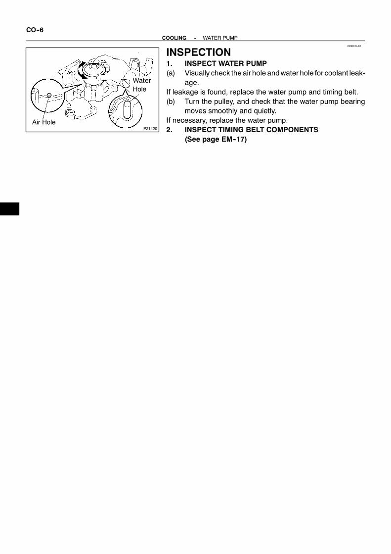
CO0CO--01
P21420Air Hole
WaterHole
CO--6--COOLING WATER PUMP
INSPECTION1. INSPECT WATER PUMP(a) Visually check the air hole andwater hole for coolant leak-
age.If leakage is found, replace the water pump and timing belt.(b) Turn the pulley, and check that the water pump bearing
moves smoothly and quietly.If necessary, replace the water pump.2. INSPECT TIMING BELT COMPONENTS
(See page EM--17)

CO0CP--01
P21421
Seal Width2--3 mm
P21399
New O--Ring
Connect
--COOLING WATER PUMPCO--7
INSTALLATION1. INSTALL WATER PUMP(a) Remove any old packing (FIPG) material and be careful
not to drop any oil on the contact surfaces of the waterpump and cylinder block.S Using a razor blade and gasket scraper, remove all
the old packing (FIPG)material from the gasket sur-faces and sealing groove.
S Thoroughly clean all components to remove all theloose material.
S Using a non--residue solvent, clean both sealingsurfaces.
(b) Apply seal packing to the water pump as shown in the il-lustration.Seal packing:Part No. 08826--00100 or equivalentS Install a nozzle that has been cut to a 2 -- 3mm(0.08
-- 0.12 in.) opening.S Parts must be assembled within 5 minutes of ap-
plication. Otherwise the material must be removedand reapplied.
S Immediately remove nozzle from the tube and rein-stall cap.
(c) Install a newO--ring to thewater bypass pipe end.
(d) Apply soapy water to the O--ring.(e) Connect the water pump to the water bypass pipe end.(f) Install the water pump with the 5 bolts, 2 stud bolts and
nut. Uniformly tighten the bolts, stud bolts and nut in sev-eral passes.Torque:Stud Bolt and Nut: 18 N·m (185 kgf·cm, 13 ft·lbf)Bolt: 21 N·m (215 kgf·cm, 15 ft·lbf)
HINT:Use bolts 30 mm (1.18 in.) in length.2. INSTALL THROTTLE BODY
(See page SF--41)3. INSTALL NO.2 IDLER PULLEY
(See page EM--19)4. INSTALL TIMING BELT
(See page EM--19)5. INSTALL WATER INLET, INLET HOUSING, NO.2 SEA
WATER HOSE, NO.3 SEA WATER HOSE AND NO.4SEA WATER HOSE ASSEMBLIES
(a) Remove any old packing (FIPG) material and be carefulnot to drop any oil on the contact surfaces of the water in-let housing and water pump.

B03030
Seal Packing Seal Width2 -- 3 mm
New O--Ring
M00027
M00026
M00025
CO--8--COOLING WATER PUMP
S Using a razor blade and gasket scraper, remove allthe old packing (FIPG)material from the gasket sur-faces and sealing groove.
S Thoroughly clean all components to remove all theloose material.
S Using a non--residue solvent, clean both sealingsurfaces.
(b) Apply seal packing to the sealing groove of water inlethousing as shown in the illustration.Seal packing:Part No. 08826--00100 or equivalentS Install a nozzle that has been cut to a 2 -- 3mm(0.08
-- 0.12 in.) opening.S Parts must be assembled within 5 minutes of ap-
plication. Otherwise the material must be removedand reapplied.
S Immediately remove nozzle from the tube and rein-stall cap.
(c) Install a new O--ring to the water inlet housing.(d) Apply soapy water on the O--ring.(e) Push the water inlet housing end into the water pump
hole.(f) Connect the water bypass hose (from the oil cooler pipe)
to the water inlet housing.(g) Install the water inlet and housing assembly with the 2
bolts. Alternately tighten the bolts.Torque:Stud Bolt and Nut 18 N·m (185 kgf·cm, 13 ft·lbf)
(h) Install the No.2 sea water hose to the sea water pump.Torque:Stud Bolt and Nut 2.5 N·m (25 kgf·cm, 22 in.·lbf)
(i) Install the No.3 sea water hose and No. 4 sea water hoseto the exhaust manifold.Torque:Stud Bolt and Nut 2.5 N·m (25 kgf·cm, 22 in.·lbf)
(j) Install the RH No. 4 sea water clamp to the idler pulleybracket.Torque:Stud Bolt and Nut 18 N·m (185 kgf·cm, 13 ft·lbf)
6. INSTALL DRIVE BELT(See page CH--17)
7. INSTALL INTAKE AIR CONNECTOR8. INSTALL V--BANK COVER

CO0CQ--01
M02781z Non--reusable part
: Specified torqueN·m (kgf·cm, ft·lbf)
19 (195, 14)
V--BankCover
♦Gasket
Thermostat
Water Inlet
--COOLING THERMOSTATCO--9
THERMOSTATCOMPONENTS
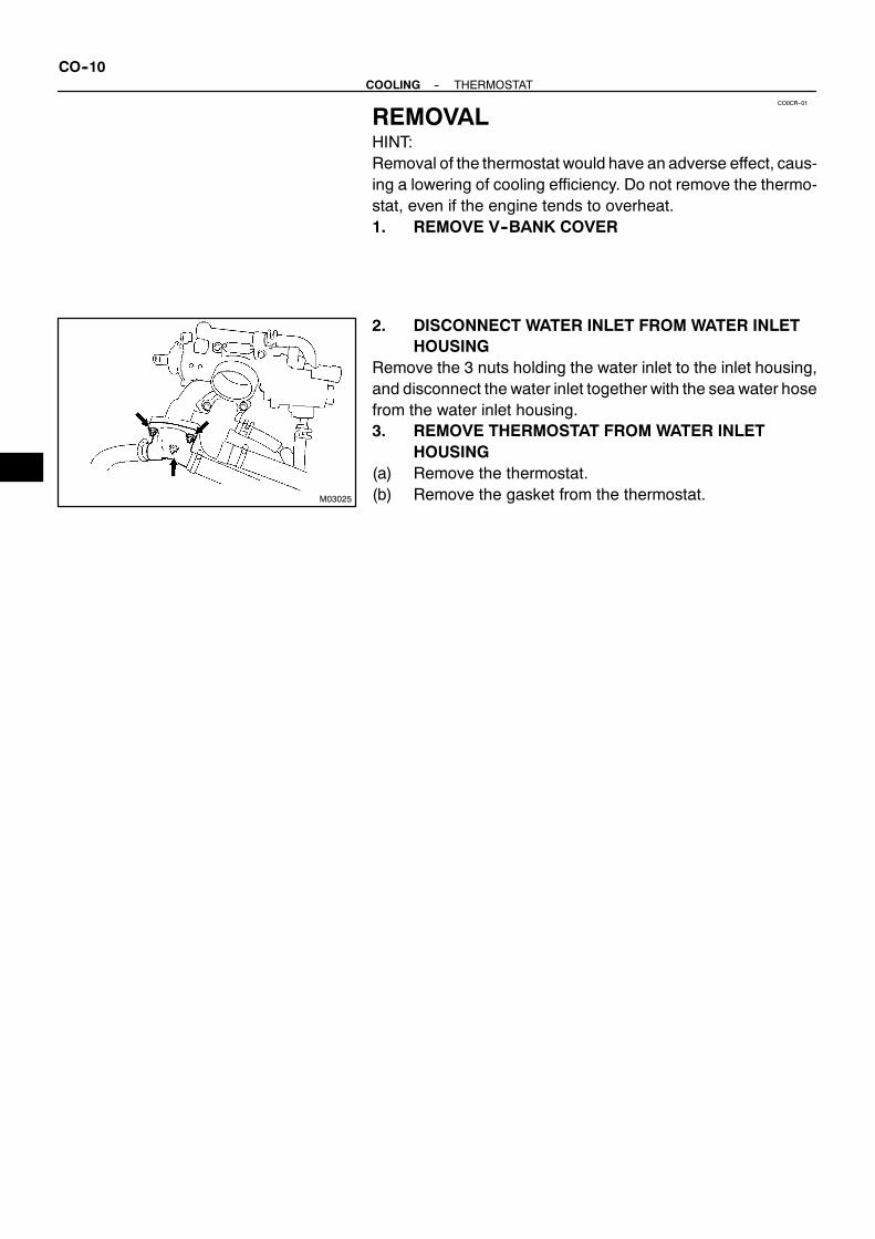
CO0CR--01
M03025
CO--10--COOLING THERMOSTAT
REMOVALHINT:Removal of the thermostat would have an adverse effect, caus-ing a lowering of cooling efficiency. Do not remove the thermo-stat, even if the engine tends to overheat.1. REMOVE V--BANK COVER
2. DISCONNECT WATER INLET FROM WATER INLETHOUSING
Remove the 3 nuts holding the water inlet to the inlet housing,and disconnect the water inlet together with the sea water hosefrom the water inlet housing.3. REMOVE THERMOSTAT FROM WATER INLET
HOUSING(a) Remove the thermostat.(b) Remove the gasket from the thermostat.

CO0CS--01
M02744
CO0929
CO0949
10 mm
--COOLING THERMOSTATCO--11
INSPECTIONINSPECT THERMOSTATHINT:The thermostat is numbered with the valve opening tempera-ture.
(a) Immerse the thermostat in water and gradually heat thewater.
(b) Check the valve opening temperature.Valve opening temperature:69 -- 73˚C (156 -- 163˚F)
If the valve opening temperature is not as specified, replace thethermostat.
(c) Check the valve lift.Valve lift:10 mm (0.39 in.) or more at 85˚C (185˚F)
If the valve lift is not as specified, replace the thermostat.(d) Check that the valve is fully closed when the thermostat
is at low temperatures (below 40˚C (104˚F)).If not closed, replace the thermostat.

CO0CT--01
M02553
CO--12--COOLING THERMOSTAT
INSTALLATION1. PLACE THERMOSTAT IN WATER INLET HOUSING(a) Install a new gasket to the thermostat.(b) Insert the thermostat into the water inlet housing with the
bypass hole facing straight upward.HINT:Install the thermostat so that the bypass hole faces upward asshown in the illustration.2. INSTALL WATER INLET
Torque: 19 N·m (195 kgf·cm, 14 ft·lbf)3. START ENGINE AND CHECK FOR COOLANT
LEAKS4. INSTALL V--BANK COVER

CO0CM--01
M02782
No.2 Sea Water Hose
No.1 Sea Water Hose
Sea Water Pump Pully
SeaWater Pump
Drive Belt
♦O--ring
×4
18 (185, 13)
98 (1,000, 72)
18 (185, 13)
N·m (kgf·cm, ft·lbf) : Specified torque♦Non--reusale part
--COOLING SEA WATER PUMPCO--13
SEA WATER PUMPCOMPONENTS

CO0CN--01
M00028
CO--14--COOLING SEA WATER PUMP
REMOVAL1. REMOVE DRIVE BELT
(See page CH--7)2. REMOVE NO.2 SEA WATER HOSELoosen the hose clamp, then remove theNo. 2 seawater hose.3. REMOVE SEA WATER PUMP(a) Loosen the clamp of No. 1 sea water hose.(b) Remove the nut and sea water pump pulley.HINT:Before removing the nut, secure the shaft of the sea waterpump with a spanner so that it does not rotate.(c) Remove the 3 bolts and the sea water pump.

CO0CO--01
M00029
--COOLING SEA WATER PUMPCO--15
INSPECTION1. REMOVE IMPELLER(a) Remove the 4 screws and the cover.(b) Remove the O--ring.(c) Remove the impeller.2. INSPECT IMPELLERVisually inspect the impeller for damage and wear.If you find any problem, replace the impeller.3. INSTALL IMPELLER(a) Install the impeller to the sea water pump.(b) Install a new O--ring on the sea water pump.(c) Install the cover with the 4 screws.

CO0CP--01
M00028
CO--16--COOLING SEA WATER PUMP
INSTALLATION1. INSTALL SEA WATER PUMP(a) Install the sea water pump with the 3 bolts.
Torque: 18 N·m (185 kgf·cm, 13 ft·lbf)(b) Tighten the hose clamp of No. 1 sea water hose.
Torque: 2.5 N·m (25 kgf·cm, 22 in.·lbf)(c) Install the nut and sea water pump pulley to the seawater
pump.HINT:Before tightening the nut, secure the shaft of the sea waterpump with a spanner so that it does not rotate.2. INSTALL NO.2 SEA WATER HOSEInstall the No. 2 sea water hose to the sea water pump.
Torque: 2.5 N·m (25 kgf·cm, 22 in.·lbf)3. INSTALL DRIVE BELT
(See page CH--17)

COOLING
WATER PUMP CO--1. . . . . . . . . . . . . . . . . . . . . . . . . . .
THERMOSTAT CO--9. . . . . . . . . . . . . . . . . . . . . . . . . .
SEA WATER PUMP CO--13. . . . . . . . . . . . . . . . . . . . . .

B00319
Recommended Viscosity (SAE):
10W--30
5w--30 PREFERRED
˚F˚C --29
--20 0--18
20--7
404
6016
8027
10038
TEMPERATURE RANGE ANTICIPATED BEFORE
NEXT OIL CHANGE
LU06O--01
M03029
M00030Oil Pressure Gauge
M01398
Adhesive
--LUBRICATION OILAND FILTERLU--1
OIL AND FILTERINSPECTION1. CHECK ENGINE OIL QUALITYCheck the oil for deterioration, entry of water, discoloring or thin-ning.If oil quality is poor, replace the oil.
Oil grade:API grade SH, Energy--Conserving II or SJ,Energy--Conserving or ILSAC multigrade engine oil.SAE 5W--30 is the best choice for your vehicle, forgood fuel economy, and good starting in coldweather.
2. CHECK ENGINE OIL LEVELThe oil level should bebetween the ”L” and ”F”markson thedip-stick.If low, check for leakage and add oil up to the ”F” mark.NOTICE:S Do not fill with engine oil above the ”F” mark.
S Install the oil dipstick and oil filler cap facing thedirection shown in the illustration.
3. REMOVE OIL PRESSURE SENDER GAUGE, ANDINSTALL OIL PRESSURE GAUGE
4. WARM UP ENGINEAllow the engine to warm up to normal operating temperature.5. CHECK OIL PRESSURE
Oil pressure:At idle29 kPa (0.3 kgf/cm2, 4.2 psi) or more
At 3,000 rpm294 -- 588 kPa (3.0 -- 6.0 kgf/cm2, 43 -- 85 psi)
6. REMOVE OIL PRESSURE GAUGE, AND REINSTALLOIL PRESSURE SENDER GAUGE
(a) Remove the oil pressure gauge.
(b) Apply adhesive to 2 or3 threadsof the oil pressure sendergauge.Adhesive:Part No. 08833--00080, THREE BOND 1344,LOCTITE 242 or equivalent
(c) Reinstall the oil pressure sender gauge.7. START ENGINE, AND CHECK FOR OIL LEAKS

LU06P--01
M00031
Drain Plug
M00551SST
Z06832
LU--2--LUBRICATION OILAND FILTER
REPLACEMENTCAUTION:S Prolonged and repeated contact with mineral oil will
result in the removal of natural fats from the skin,leading to dryness, irritation and dermatitis. In addi-tion, used engine oil contains potentially harmfulcontaminants which may cause skin cancer.
S Care should be taken, therefore, when changing en-gine oil to minimize the frequency and length of timeyour skin is exposed to used engine oil. Protectiveclothing and gloves that cannot be penetrated by oilshould be worn. The skin should be thoroughlywashed with soap and water, or use water--less handcleaner, to remove any used engine oil. Do not usegasoline, thinners, or solvents.
S In order to preserve the environment, used oil andused oil filters must be disposed of only at desig-nated disposal sites.
1. DRAIN ENGINE OIL(a) Remove the oil filler cap.(b) Remove the oil drain plug, and drain the oil into a contain-
er.(c) Use the vacuum pump to drain the engine oil.
2. REPLACE OIL FILTER(a) Using SST, remove the oil filter.
SST 09228--07501
(b) Clean the oil filter contact surface on the oil filter mount-ing.
(c) Lubricate the filter rubber gasket with clean engine oil.(d) Tighten the oil filter by hand until the rubber gasket con-
tacts the seat of the filter mounting.

LU04903/4 Turn
SST
--LUBRICATION OILAND FILTERLU--3
(e) Using SST, give it an additional 3/4 turn to seat the filter.SST 09228--07501
3. REFILL WITH ENGINE OIL(a) Clean the drain plug, and install a new gasket and it.
Torque: 34 N·m (340 kgf·cm, 24 ft·lbf)(b) Fill with new engine oil.
Oil grade:See step 1 in oil pressure checkCapacity:Drain and refillw/ Oil filter change5.3 liters (5.6 US qts, 4.9 lmp. qts)
w/o Oil filter change5.0 liters (5.3 US qts, 4.4 lmp. qts)
Dry fill7.0 liters (7.4 US qts, 6.2 lmp. qts)
(c) Reinstall the oil filler cap.4. START ENGINE AND CHECK FOR OIL LEAKS5. RECHECK ENGINE OIL LEVEL

LU06Q--01
M04284
Water Bypass Hose
Camshaft PositionSensor Connector
Drive Belt Idler Pulley
Cover Plate
Gasket
RH No.3 TimingBelt Cover
No.2 TimingBelt Cover
Engine Wire
7.5 (80, 66 in.·lbf)
16 (160, 12)
39 (400, 29)
7.5 (80, 66 in.·lbf)
N·m (kgf·cm, ft·lbf) : Specified Torque
18 (185,13)
Water Inlet HousingAssembly
SeaWater Hose
Oil Cooler Pipe
LH No.3 TimingBelt Cover
Gasket
M03072
Timing Belt
TimingBelt Tensioner
LH Camshaft Timing Pulley
Fan Bracket
RH Camshaft Timing Pulley
N·m (kgf·cm, ft·lbf) : Specified torque
7.5 (80, 66 in.·lbf)
16 (160, 12)
32 (330, 24)
245 (2,500, 181)
38 (390, 28)Sea Water Pump
LU--4--LUBRICATION OIL PUMP
OIL PUMPCOMPONENTS
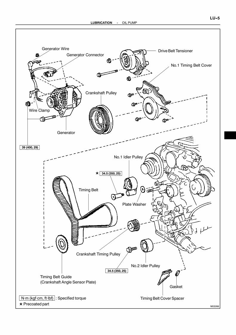
M03266
N·m (kgf·cm, ft·lbf) : Specified torque
LPrecoated part
Generator Wire
Generator Connector
Wire Clamp
Generator
Crankshaft Pulley
DriveBelt Tensioner
No.1 Timing Belt Cover
Timing Belt
Timing Belt Guide(Crankshaft Angle Sensor Plate)
No.2 Idler Pulley
TimingBelt Cover Spacer
Gasket
No.1 Idler Pulley
Crankshaft Timing Pulley
34.5 (350, 25)
34.5 (350, 25)
L
39 (400, 29)
Plate Washer
--LUBRICATION OIL PUMPLU--5

M02780
x 12
z Gasket
z O--Ring
Oil Strainer
Oil DipstickGuide andDipstick
Oil Filter and FilterBracket Assembly
CrankshaftPositionSensor
CrankshaftPosition Sensor Connector
Oil Pump
z Gasket
Oil Drain Hose
Oil Pan Baffle Plate
No.1 Oil Pan
No.2 Oil Pan
x 16
zNon--reusable part
z O--Ring
: Specified torqueN·m (kgf·cm, ft·lbf)
z Gasket
x 6
z Gasket
15.5 (160, 11)
18 (185, 13)
15.5 (160, 11)
30.5 (310, 22)
Oil PressureSenderGaugeConnector
LU--6--LUBRICATION OIL PUMP

B02772
Oil Pump Body
Driven Rotor
Drive Rotor
x 10
Relief Valve
Compression Spring
Oil Pump Body Cover
z Non--reusable part
zCrankshaft Front Oil Seal
Plug49 (500, 36)
: Specified torqueN·m (kgf·cm, ft·lbf)
--LUBRICATION OIL PUMPLU--7

LU06R--01
M03035
B02756
P01132
SSTSST
LU--8--LUBRICATION OIL PUMP
REMOVALHINT:When repairing the oil pump, the oil pan and strainer should beremoved and cleaned.1. REMOVE ENGINE FROM BOAT
(See page EM--69)2. SEPARATE ENGINE AND TRANSMISSION
(See page EM--69)3. INSTALL ENGINE TO ENGINE STAND FOR
DISASSEMBLY4. REMOVE TIMING BELT
(See page EM--12)5. REMOVE NO.2 AND NO.1 IDLER PULLEYS
(See page EM--12)6. REMOVE CRANKSHAFT TIMING PULLEY
(See page EM--12)
7. REMOVE OIL DIPSTICK AND GUIDE(a) Remove the bolt holding the oil dipstick to the LH cylinder
head.(b) Pull out the dipstick guide together with the dipstick from
the No.1 oil pan.(c) Remove the O--ring from the dipstick guide.
8. REMOVE NO.2 OIL PAN(a) Remove the 12 bolts and 2 nuts.
(b) Insert the blade of SST between the No.1 and No.2 oilpans, cut off applied sealer and remove the No.2 oil pan.SST 09032--00100
NOTICE:S Be careful not to damage theNo.2 oil pan contact sur-
face of the No.1 oil pan.S Be careful not to damage the No.2 oil pan flange.

B02757
B02758
B02759
Pry
(A)
(A)
(A)
M00558
--LUBRICATION OIL PUMPLU--9
9. REMOVE OIL PAN BAFFLE PLATERemove the 6 bolts, 2 nuts and baffle plate.
10. REMOVE NO.1 OIL PAN(a) Remove the 16 bolts and 2 nuts.
(b) Using a screwdriver, remove theNo.1 oil panby prying theportions (A) between the cylinder block and No.1 oil pan.
NOTICE:Be careful not to damage the contact surfaces of the cylin-der block and No.1 oil pan.11. REMOVE OIL STRAINERRemove the 2 bolts, 2 nuts, oil strainer and gasket.
12. REMOVE OIL FILTER AND FILTER BRACKETASSEMBLY
(a) Disconnect the oil pressure sender gauge connector.(b) Disconnect the oil cooler hose (from the cooler drain
union) from the oil cooler.(c) Remove the stud bolt and bolt, nut the oil filter and filter
bracket assembly.(d) Remove the gasket from the filter bracket.

LU1178
B02760
P00073
LU--10--LUBRICATION OIL PUMP
13. REMOVE CRANKSHAFT POSITION SENSOR(a) Disconnect the crankshaft position sensor connector.(b) Remove the bolt and crankshaft position sensor.
14. REMOVE OIL PUMP(a) Remove the 7 bolts and hexagon socket head bolt.
(b) Using a screwdriver, remove the oil pump by prying theportions between the oil pump and cylinder block.
NOTICE:Be careful not to damage the contact surfaces of the cylin-der block and oil pump.(c) Remove the O--ring from the cylinder block.
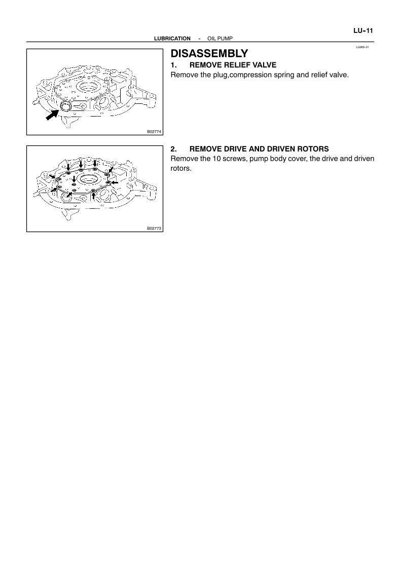
LU06S--01
B02774
B02773
--LUBRICATION OIL PUMPLU--11
DISASSEMBLY1. REMOVE RELIEF VALVERemove the plug,compression spring and relief valve.
2. REMOVE DRIVE AND DRIVEN ROTORSRemove the 10 screws, pump body cover, the drive and drivenrotors.

LU06T--01
B00955
B02775
Mark
B02776
B00958
B02777
LU--12--LUBRICATION OIL PUMP
INSPECTION1. INSPECT RELIEF VALVECoat the valve with engine oil and check that it falls smoothlyinto the valve hole by its own weight.If it doesn’t, replace the relief valve. If necessary, replace the oilpump assembly.
2. PLACEDRIVEANDDRIVENROTORS INTOOILPUMPBODY
Place the drive and driven rotors into the oil pump body with themark facing upward.
3. INSPECT ROTOR TIP CLEARANCEUsing a feeler gauge,measure the clearancebetween thedriveand driven rotor tips.
Standard tip clearance:0.110 -- 0.240 mm (0.0043 -- 0.0094 in.)Maximum tip clearance:0.35 mm (0.0138 in.)
If the tip clearance is greater than maximum, replace the rotorsas a set.
4. INSPECT ROTOR SIDE CLEARANCEUsing a feeler gauge and precision straight edge, measure theclearance between the rotors and precision straight edge.
Standard body clearance:0.030 -- 0.090 mm (0.0012 -- 0.0035 in.)Maximum body clearance:0.15 mm (0.0059 in.)
If the side clearance is greater than maximum, replace the ro-tors as a set. If necessary, replace the oil pump assembly.5. INSPECT ROTOR BODY CLEARANCEUsing a feeler gauge, measure the clearance between the driv-en rotor and body.
Standard body clearance:0.100 -- 0.175 mm (0.0039 -- 0.0069 in.)Maximum body clearance:0.30 mm (0.0118 in.)
If the body clearance is greater than maximum, replace the ro-tors as a set. If necessary, replace the oil pump assembly.6. REMOVE DRIVE AND DRIVEN ROTORS

LU06U--01
--LUBRICATION OIL PUMPLU--13
REPLACEMENTREPLACE CRANKSHAFT FRONT OIL SEAL(See page EM--96)

LU06V--01
B02775
Mark
B02774
LU--14--LUBRICATION OIL PUMP
REASSEMBLY1. INSTALL DRIVE AND DRIVEN ROTORS(a) Place the drive and driven rotors into pump body with the
marks facing the pump body cover side.(b) Install the oil pump body cover with the 10 screws.
Torque: 10 N·m (105 kgf·cm, 7 ft·lbf)
2. INSTALL RELIEF VALVE(a) Insert these parts into the oil pump body hole:
S Relief valveS Compression spring
(b) Install the plug.Torque: 49 N·m (500 kgf·cm, 36 ft·lbf)

LU06W--01
B02778
A
B
A
B
Seal Width2 -- 3 mm
P21388
New O--Ring
Engage
B02761
E
C
A
DB
CC
C
--LUBRICATION OIL PUMPLU--15
INSTALLATION1. INSTALL OIL PUMP(a) Remove any old packing (FIPG) material and be careful
not to drop any oil on the contact surfaces of the oil pumpand cylinder block.S Using a razor blade and gasket scraper, remove all
the old packing (FIPG)material from the gasket sur-faces and sealing groove.
S Thoroughly clean all components to remove all theloose material.
S Using a non--residue solvent, clean both sealingsurfaces.
(b) Apply seal packing to the oil pumpas shown in the illustra-tion.Seal packing:Part No. 08826--00080 or equivalent
NOTICE:Avoidapplying anexcessive amount to thesurface. Bepar-ticularly careful near oil passage.
S Install a nozzle that has been cut to a 2 -- 3mm(0.08-- 0.12 in.) opening.
S Parts must be assembled within 5 minutes of ap-plication. Otherwise the material must be removedand reapplied.
S Immediately remove nozzle from the tube and rein-stall cap.
(c) Install a new O--ring to the cylinder block.(d) Engage the spline teeth of the oil pump drive gearwith the
large teeth of the crankshaft, and slide the oil pump on thecrankshaft.
(e) Install the oil pump with the 8 bolts. Uniformly tighten thebolts in several passes.Torque:12 mm head and 6 mm hexagon socket head15.5 N·m (160 kgf·cm, 11 ft·lbf)
14 mm head30.5 N·m (310 kgf·cm, 22 ft·lbf)
HINT:S Use a 6 mm hexagon wrench for the hexagon socket
head bolt.S Each bolt length is indicated in the illustration.Bolt length:50 mm (1.97 in.) for A of 12 mm head106 mm (4.17 in.) for B of 12 mm head30 mm (1.18 in.) for C of 12 mm head44 mm (1.57 in.) for D of 14 mm head28 mm (1.18 in.) for E of 6 mm hexagon socket head

LU1178
P00213New O--Ring
M00558
B02762
LU--16--LUBRICATION OIL PUMP
2. INSTALL CRANKSHAFT POSITION SENSOR(a) Install the crankshaft position sensor with the bolt.
Torque: 6.5 N·m (65 kgf·cm, 58 in.·lbf)(b) Connect the crankshaft position sensor connector.
3. INSTALL OIL FILTER AND FILTER BRACKETASSEMBLY
(a) Install a new gasket to the oil filter bracket.
(b) Install the oil filter and filter bracket assemblywith the studbolt, bolt and nut.Torque: 18 N·m (185 kgf·cm, 13 ft·lbf)
(c) Connect the oil cooler hose (from the coolant drain union)to the oil cooler.
(d) Connect the oil pressure sender gauge connector.
4. INSTALL OIL STRAINERInstall a new gasket and the oil strainer with the 2 bolts and 2nuts.
Torque: 7.5 N·m (80 kgf·cm, 66 in.·lbf)HINT:Use bolts 12 mm (0.47 in.) in length.5. INSTALL NO.1 OIL PAN(a) Remove any old packing (FIPG) material and be careful
not to drop any oil on the contact surfaces of the No.1 oilpan, cylinder block, oil pump and rear oil seal retainer.S Using a razor blade and gasket scraper, remove all
the old packing (FIPG)material from the gasket sur-faces and sealing groove.
S Thoroughly clean all components to remove all theloose material.
S Using a non--residue solvent, clean both sealingsurfaces.
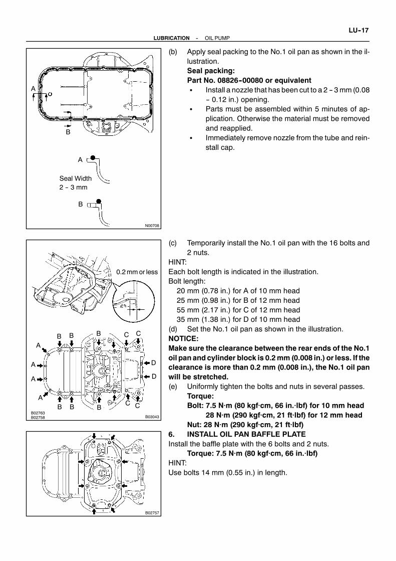
N00708
A
A
B
B
Seal Width2 -- 3 mm
B02763B02758 B03043
0.2mmor less
A
B
C
DA
A
A
B B
B
B
B
C
C C
D
B02757
--LUBRICATION OIL PUMPLU--17
(b) Apply seal packing to the No.1 oil pan as shown in the il-lustration.Seal packing:Part No. 08826--00080 or equivalentS Install a nozzle that has been cut to a 2 -- 3mm(0.08
-- 0.12 in.) opening.S Parts must be assembled within 5 minutes of ap-
plication. Otherwise the material must be removedand reapplied.
S Immediately remove nozzle from the tube and rein-stall cap.
(c) Temporarily install the No.1 oil pan with the 16 bolts and2 nuts.
HINT:Each bolt length is indicated in the illustration.Bolt length:20 mm (0.78 in.) for A of 10 mm head25 mm (0.98 in.) for B of 12 mm head55 mm (2.17 in.) for C of 12 mm head35 mm (1.38 in.) for D of 10 mm head
(d) Set the No.1 oil pan as shown in the illustration.NOTICE:Make sure the clearance between the rear ends of the No.1oil pan andcylinder block is 0.2mm (0.008 in.) or less. If theclearance is more than 0.2 mm (0.008 in.), the No.1 oil panwill be stretched.(e) Uniformly tighten the bolts and nuts in several passes.
Torque:Bolt: 7.5 N·m (80 kgf·cm, 66 in.·lbf) for 10 mm head
28 N·m (290 kgf·cm, 21 ft·lbf) for 12 mm headNut: 28 N·m (290 kgf·cm, 21 ft·lbf)
6. INSTALL OIL PAN BAFFLE PLATEInstall the baffle plate with the 6 bolts and 2 nuts.
Torque: 7.5 N·m (80 kgf·cm, 66 in.·lbf)HINT:Use bolts 14 mm (0.55 in.) in length.

B02764
Seal Width3 -- 4 mm
A B
A
B
B02756
LU--18--LUBRICATION OIL PUMP
7. INSTALL NO.2 OIL PAN(a) Remove any old packing (FIPG) material and be careful
not to drop any oil on the contact surfaces of the No.1 andNo.2 oil pans.S Using a razor blade and gasket scraper, remove all
the old packing (FIPG)material from the gasket sur-faces and sealing groove.
S Thoroughly clean all components to remove all theloose material.
S Using a non--residue solvent, clean both sealingsurfaces.
NOTICE:Do not use a solvent whichwill affect the painted surfaces.(b) Apply seal packing to the No.2 oil pan as shown in the il-
lustration.Seal packing:Part No. 08826--00080 or equivalentS Install a nozzle that has been cut to a 3 -- 4mm(0.12
-- 0.16 in.) opening.S Parts must be assembled within 5 minutes of ap-
plication. Otherwise the material must be removedand reapplied.
S Immediately remove nozzle from the tube and rein-stall cap.
(c) Install the No.2 oil pan with the 12 bolts and 2 nuts. Uni-formly tighten the bolts and nuts in several passes.Torque:Bolt: 7.5 N·m (80 kgf·cm, 66 in.·lbf)Nut: 28 N·m (290 kgf·cm, 21 ft·lbf)
HINT:Use bolts 14 mm (0.55 in.) in length.
8. INSTALL OIL DIPSTICK GUIDE AND DIPSTICK(a) Install a new O--ring to the dipstick guide.(b) Apply soapy water to the O--ring.(c) Push in the dipstick guide end into the guide hole of the
No.1 oil pan.(d) Install the dipstick guide with the bolt.(e) Install the dipstick.

--LUBRICATION OIL PUMPLU--19
9. INSTALL CRANKSHAFT TIMING PULLEY(See page EM--19)
10. INSTALL NO.1 AND NO.2 IDLER PULLEYS(See page EM--19)
11. INSTALL TIMING BELT(See page EM--19)
12. DISCONNECT ENGINE FROM ENGINE STAND13. REASSEMBLE ENGINE AND TRANSMISSION
(See page EM--72)14. INSTALL ENGINE TO BOAT
(See page EM--72)

LUBRICATION
OIL AND FILTER LU--1. . . . . . . . . . . . . . . . . . . . . . . . .
OIL PUMP LU--4. . . . . . . . . . . . . . . . . . . . . . . . . . . . . .

IG06Z--01
M02753
--IGNITION IGNITION SYSTEMIG--1
IGNITION SYSTEMON--BOAT INSPECTIONNOTICE:”Cold” and ”Hot” in these sentences express the tempera-ture of the coils themselves. ”Cold” is from --10˚C (14˚F) to50˚C (122˚F) and ”Hot” is from 50˚C (122˚F) to 100˚C(212˚F).
1. INSPECT IGNITION COIL WITH IGNITER ANDSPARK TEST
Check that the spark occurs.(1) Remove the ignition coil with igniters.
(See page IG--6)(2) Using a 16 mm plug wrench, remove the spark
plugs.(3) Install the spark plugs to each ignition coil with ignit-
er, and connect the ignition coil with igniter connec-tor.
(4) Disconnect the injector connector.(5) Ground the spark plug.(6) Check if spark occurs while engine is being
cranked.

CHECK POWER SUPPLY TO IGNITION COILWITH
SENSOR
SPARK TEST
Replace the crankshaft position sensor.
CHECK RESISTANCE OF CAMSHAFT POSITION
(See step 4)
1. Turn ignition switch to ON.2. Check that there is battery voltage at ignition coil positive (+)
terminal.
CHECK CONNECTION OF IGNITION COIL WITH
Resistance:Cold Hot
1,060 -- 1,645Ω
CHECKRESISTANCEOFCRANKSHAFTPOSITION
(See step 4)Resistance:
Cold Hot1,630 -- 2,740Ω 2,065 -- 3,225 Ω
CHECK IGT SIGNAL FROM ECM(See page DI--66)
TRY ANOTHER IGNITION COIL WITH IGNITER
Replace the camshaft position sensor.
Connect securely.
Check wiring between ignition switchto ignition coil with igniter.
Check wiring between ECM and ignitioncoil with igniter, and then try another ECM.
NO
OK
OK
OK
OK
BAD
BAD
BAD
BAD
BAD
SENSOR
835 -- 1,400Ω
IGNITER
CHANGE IT TO NORMAL IGNITION COIL WITHIGNITER AND PERFORM SPARK TEST AGAIN OK
Replace the ignition coil with igniter.
NO
OK
IGNITER CONNECTOR
IG--2--IGNITION IGNITION SYSTEM
NOTICE:To prevent gasoline frombeing injected from injectors dur-ing this test, crank the engine for no more than 5 -- 10 se-conds at time. If the spark done not occur, do the test as fol-lows:
(7) Using a 16mm plug wrench, install the spark plugs.Torque: 17.5 N·m (180 kgf·cm, 13 ft·lbf)(8) Reinstall the ignition coil with igniters.
(See page IG--7)2. INSPECT SPARK PLUGSNOTICE:S Never use a wire brush for cleaning.S Never attempt to adjust the electrode gap on used
spark plug.S Spark plug should be replaced every 1,000 Hr.(a) Remove the ignition coil with igniters.
(See page IG--6)

IG0147
Megger
Ground
B01301
M02754
16mmPlugWrench
IG0316
B02101
1.1 mm
--IGNITION IGNITION SYSTEMIG--3
(b) Check the electrode.S Using amegger (insulation resistance meter), mea-
sure the insulation resistance.Correct insulation resistance:10 MΩ or more
If the resistance is less than specified, proceed to step (d).HINT:If a megger is not available, the following simple method of in-spection provides fairly accurate results.
S Simple Method:S Quickly race the engine to 4,000 rpm 5 times.S Remove the spark plug. (See step (c))S Visually check the spark plug.
If the electrode is dry ... Okay.If the electrode is wet ... Proceed to step (d).
S Reinstall the spark plug. (See step (g))
(c) Using a 16 mm plug wrench, remove the spark plugs.
(d) Check the spark plug for thread damage and insulatordamage.
If abnormal, replace the spark plug.Recommended spark plug:
DENSO SK20R11
NGK IFR6A11
(e) Check the spark plug electrode gap.Maximum electrode gap for used spark plug:1.2 mm (0.047 in.)
If the gap is greater than maximum, replace the spark plug.Correct electrode gap for new spark plug:1.1 mm (0.043 in.)
NOTICE:If adjusting the gapof a new spark plug, bendonly the baseof the groundelectrode. Donot touch the tip. Never attemptto adjust the gap on a used plug.
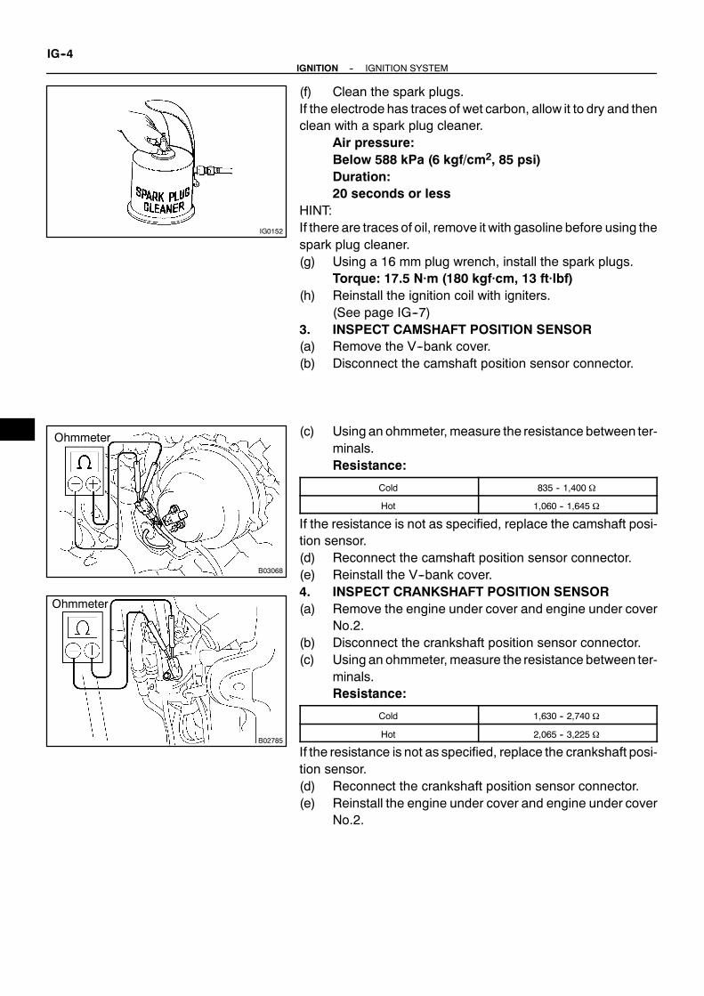
IG0152
B03068
Ohmmeter
B02785
Ohmmeter
IG--4--IGNITION IGNITION SYSTEM
(f) Clean the spark plugs.If the electrode has traces of wet carbon, allow it to dry and thenclean with a spark plug cleaner.
Air pressure:Below 588 kPa (6 kgf/cm2, 85 psi)Duration:20 seconds or less
HINT:If there are traces of oil, remove it with gasoline before using thespark plug cleaner.(g) Using a 16 mm plug wrench, install the spark plugs.
Torque: 17.5 N·m (180 kgf·cm, 13 ft·lbf)(h) Reinstall the ignition coil with igniters.
(See page IG--7)3. INSPECT CAMSHAFT POSITION SENSOR(a) Remove the V--bank cover.(b) Disconnect the camshaft position sensor connector.
(c) Using an ohmmeter, measure the resistance between ter-minals.Resistance:
Cold 835 -- 1,400 Ω
Hot 1,060 -- 1,645 Ω
If the resistance is not as specified, replace the camshaft posi-tion sensor.(d) Reconnect the camshaft position sensor connector.(e) Reinstall the V--bank cover.4. INSPECT CRANKSHAFT POSITION SENSOR(a) Remove the engine under cover and engine under cover
No.2.(b) Disconnect the crankshaft position sensor connector.(c) Using an ohmmeter, measure the resistance between ter-
minals.Resistance:
Cold 1,630 -- 2,740 Ω
Hot 2,065 -- 3,225 Ω
If the resistance is not as specified, replace the crankshaft posi-tion sensor.(d) Reconnect the crankshaft position sensor connector.(e) Reinstall the engine under cover and engine under cover
No.2.
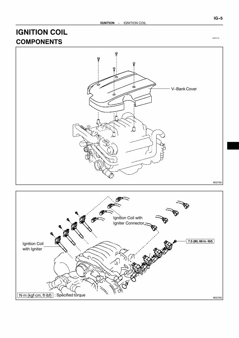
IG070--01
M02785
V--BankCover
M02783
Ignition Coil withIgniter Connector
Ignition Coilwith Igniter
7.5 (80, 66 in.·lbf)
N·m (kgf·cm, ft·lbf) : Specified torque
--IGNITION IGNITION COILIG--5
IGNITION COILCOMPONENTS

IG071--01
M03069
IG--6--IGNITION IGNITION COIL
REMOVAL1. REMOVE V--BANK COVER2. DISCONNECT IGNITION COIL WITH IGNITER
CONNECTORS3. REMOVE IGNITION COIL WITH IGNITERS FROM
SPARK PLUGSRemove the bolt.
Torque: 7.5 N·m (80 kgf·cm, 66 in.·lbf)

IG072--01
--IGNITION IGNITION COILIG--7
INSTALLATIONInstallation is in the reverse order of removal.(See page IG--6)

IG073--01
M02785
V--Bank Cover
M03026
Camshaft Position Sensor
Oil Cooler Pipe
LH No.3 Timing Belt Cover
GasketCamshaft Position SensorConnector
7.5 (80, 66 in.·lbf)
7.5 (80, 66 in.·lbf)
N·m (kgf·cm, ft·lbf) : Specified torque
Engine Wire
IG--8--IGNITION CAMSHAFT POSITION SENSOR
CAMSHAFT POSITION SENSORCOMPONENTS

IG074--01
M00032
B01293
--IGNITION CAMSHAFT POSITION SENSORIG--9
REMOVAL1. REMOVE V--BANK COVER2. REMOVE NO.3 SEA WATER HOSE AND NO.4 SEA
WATER HOSE3. REMOVE NO.2 SEA WATER HOSE4. REMOVE NO.3 TIMING BELT COVER
(See page EM--12)5. DISCONNECT CAMSHAFT POSITION SENSOR
CONNECTOR
6. REMOVE CAMSHAFT POSITION SENSORRemove the bolt, stud bolt and camshaft position sensor.

IG075--01
B01293
M00032
IG--10--IGNITION CAMSHAFT POSITION SENSOR
INSTALLATION1. INSTALL CAMSHAFT POSITION SENSOR
Torque:Bolt: 7.5 N·m (80 kgf·cm, 66 in.·lbf)Stud bolt: 7.5 N·m (80 kgf·cm, 66 in.·lbf)
2. CONNECT CAMSHAFT POSITION SENSORCONNECTOR
3. INSTALL NO.3 TIMING BELT COVER(See page EM--19)
4. INSTALL NO.2 SEA WATER HOSE5. INSTALLNO.3 SEAWATERHOSEANDNO.4 SEAWA-
TER HOSE6. INSTALL V--BANK COVER7. CHECK ENGINE COOLANT FOR LEAKS8. CHECK IGNITION TIMING
(See page EM--7)

IG076--01
M03063
CrankshaftPosition Sensor
Crankshaft Position SensorConnector6.5 (65, 58 in.·lbf)
N·m (kgf·cm, ft·lbf) : Specified torque
--IGNITION CRANKSHAFT POSITION SENSORIG--11
CRANKSHAFT POSITION SENSORCOMPONENTS

IG077--01
M21883
IG--12--IGNITION CRANKSHAFT POSITION SENSOR
REMOVAL1. DISCONNECT CRANKSHAFT POSITION SENSOR
CONNECTOR2. REMOVE CRANKSHAFT POSITION SENSOR
Torque: 6.5 N·m (65 kgf·cm, 58 in.·lbf)

IG078--01
--IGNITION CRANKSHAFT POSITION SENSORIG--13
INSTALLATIONInstallation is in the reverse order of removal.(See page IG--12)

IGNITION
IGNITION SYSTEM IG--1. . . . . . . . . . . . . . . . . . . . . .
IGNITION COIL IG--5. . . . . . . . . . . . . . . . . . . . . . . . . .
CAMSHAFT POSITION SENSOR IG--8. . . . . . . . . .
CRANKSHAFT POSITION SENSOR IG--11. . . . . . .

ST063--01
--STARTING STARTING SYSTEMST--1
STARTING SYSTEMON--BOAT INSPECTIONNOTICE:Before changing the starter, check these items again:S Connector connectionS Accessory installation, e.g.: theft deterrent system

ST064--01
M04118
V--Bank Cover
Throttle Cable
Intake Air Connector
ST--2--STARTING STARTER
STARTERCOMPONENTS

M03039
Wiring HarnessClamp Bracket
RearWater Bypass Joint
Injector Connector
Fuel Pressure PulsationDamper
Fuel InletHose
Throttle PositionSensor Connector
V--BankCover Bracket
Water BypassPipe
Starter
Throttle ControlMotor Connector
AcceleratorPosition SensorConnector
Noise Filter Connector
z O--Ring
zGasket
z Gasket
VSV Connectorfor ACIS
V--Bank Cover BracketSub Assebly
Water Bypass PipeBracket
zNon--reusable part
z Gasket
Throttle Body
Camshaft PositionSensor Connector
Engine Wire
Throttle ControlCable Bracket
z Gasket
IntakeManifoldAssembly
Fuel Hose
z Gasket
--STARTING STARTERST--3

B00968
z O--Ring
Idler GearStarter HousingAssembly
ReturnSpring
Starter ClutchAssembly
O--Ring
Steel Ball
Contact Plate
zRear Bearing
Armature
Magnetic SwitchAssembly
Bearing
zDust Protector
z Front Bearing
zO--Ring
End Cover
Brush Holder
FieldFrame (FieldCoil)
Terminal Insulator
Magnetic Switch Assembly
Wave WasherTerminal Nut
O--RingTerminal Insulator
Terminal BoltzTerminalC Kit Part
Lead TerminalPlunger
z Gasket
End Cover
Terminal Insulator
Terminal Bolt
Contact Plate
Terminal Insulator
WaveWasher
O--Ring
Terminal Nut
zTerminal 30Kit Part
z Non--reusable part
LeadClamp
Packing
ST--4--STARTING STARTER

ST065--01
B00966
M00967
StarterConnector
StarterCable
--STARTING STARTERST--5
REMOVAL1. REMOVE V--BANK COVER2. DISCONNECT THROTTLE CABLE3. REMOVE INTAKE AIR CONNECTOR4. DISCONNECT THROTTLE BODY
(See page SF--56)5. REMOVE INTAKE MANIFOLD ASSEMBLY
(See page EM--29)
6. REMOVE STARTER(a) Remove the 2 bolts holding the starter to the cylinder
block.(b) Disconnect the starter from the cylinder block.
(c) Disconnect the starter connector.(d) Remove the nut, and disconnect the starter wire.

ST066--01
P25331Dust Protector
P21084
B00969
B01027
(2)
(3)
(1)
(4)
(5)
ST0948
Magnetic Finger
ST--6--STARTING STARTER
DISASSEMBLY1. REMOVE DUST PROTECTOR2. REMOVE FIELD FRAME AND ARMATURE(a) Remove the nut, and disconnect the lead wire from the
magnetic switch terminal.Torque: 5.9 N·m (60 kgf·cm, 52 in.·lbf)
(b) Remove the 2 through bolts.Torque: 9.3 N·m (95 kgf·cm, 82 in.·lbf)
(c) Pull out the field frame together with the armature.NOTICE:At the time of notice, please refer to the following items.Align the protrusionof the field framewith thegroove of themagnetic switch.(d) Remove the O--ring from the field frame.HINT:At the time of assembly, please refer to the following items.Use a new O--ring.
3. REMOVE STARTER HOUSING, CLUTCHASSEMBLY AND GEAR
(a) Remove the 2 screws.Torque: 9.3 N·m (95 kgf·cm, 82 in.·lbf)
(b) Remove these parts from the magnetic switch:(1) Starter housing(2) Return spring(3) Idler gear(4) Bearing(5) Starter clutch assembly
HINT:At the time of assembly, please refer to the following items.Apply grease to the return spring and insert the return springinto the clutch shaft hole.4. REMOVE STEEL BALLUsing a magnetic finger, remove the steel ball from the clutchshaft hole.HINT:At the time of assembly, please refer to the following items.Apply grease to the steel ball and insert the steel ball into theclutch shaft hole.

P25332
P10568
--STARTING STARTERST--7
5. REMOVE BRUSH HOLDER(a) Remove the 2 screws, and end cover from the field frame.
Torque: 3.8 N·m (39 kgf·cm, 34 in.·lbf)(b) Remove the O--ring from the field frame.HINT:At the time of assembly, please refer to the following items.Use a new O--ring.
(c) Using a screwdriver, hold the spring back and disconnectthe brush from the brush holder. Disconnect the 4brushes, and remove the brush holder.
NOTICE:Check that the positive (+) lead wires are not grounded.6. REMOVE ARMATURE FROM FIELD FRAME

ST067--01
S00054
Ohmmeter Continuity
S00055
Ohmmeter No Continuity
S00056
S00057
ST0040
ST--8--STARTING STARTER
INSPECTION1. INSPECT COMMUTATOR FOR OPEN CIRCUITUsing an ohmmeter, check that there is continuity between thesegments of the commutator.If there is no continuity between any segment, replace the ar-mature.
2. INSPECT COMMUTATOR FOR GROUNDUsing an ohmmeter, check that there is no continuity betweenthe commutator and armature coil core.If there is continuity, replace the armature.3. INSPECT COMMUTATOR FOR DIRTY AND BURNT
SURFACEIf the surface is dirty or burnt, correct it with sandpaper (No.400)or on a lathe.
4. INSPECT COMMUTATOR CIRCLE RUNOUT(a) Place the commutator on V--blocks.(b) Using a dial indicator the circle runout.
Maximum circle runout:0.05 mm (0.0020 in.)
If the circle runout is greater thanmaximum, correct it on a lathe.
5. INSPECT COMMUTATOR DIAMETERUsing vernier calipers, measure the commutator diameter.
Standard diameter:35.0 mm (1.378 in.)Minimum diameter:34.0 mm (1.339 in.)
If the diameter is less than minimum, replace the armature.
6. INSPECT UNDERCUT DEPTHCheck that the undercut depth is clean and free of foreignmate-rials. Smooth out the edge.
Standard undercut depth:0.7 mm (0.028 in.)Minimum undercut depth:0.2 mm (0.008 in.)
If the undercut depth is less than minimum, correct it with ahacksaw blade.

P10588
Ohmmeter
Continuity
S02267
Ohmmeter
(B)(A)
Z00037
ST0019
P21088
Ohmmeter
No Continuity
--STARTING STARTERST--9
7. INSPECT FIELD COIL FOR OPEN CIRCUITUsing an ohmmeter, check that there is continuity between thelead wire and field coil brush lead.If there is no continuity, replace the field frame.
8. INSPECT SHUNT COIL FOR OPEN CIRCUITUsing an ohmmeter, measure the resistance between shuntcoil terminals (A) and (B).
Resistance:1.5 -- 1.9 Ω at 20 ˚C (68 ˚F)
If the resistance is not as specified, replace the field frame.
9. INSPECT BRUSH LENGTHUsing vernier calipers, measure the brush length.
Standard length:15.0 mm (0.591 in.)Minimum length:9.0 mm (0.354 in.)
If the length is less thanminimum, replace the brush holder andfield frame.
10. INSPECT BRUSH SPRING LOADTake the pull scale reading the instant the brush spring sepa-rates from the brush.
Standard spring installed load:21.5 -- 27.5 N (2.2 -- 2.8 kgf, 4.8 -- 6.2 lbf)Minimum spring installed load:12.7 N (1.3 kgf, 2.9 lbf)
If the installed load is less than minimum, replace the brushsprings.
11. INSPECT BRUSH HOLDER INSULATIONUsing an ohmmeter, check that there is no continuity betweenthe positive (+) and negative (--) brush holders.If there is continuity, repair or replace the brush holder.

P10821
Free
Lock
B01028Terminal C
Terminal 50
Continuity Ohmmeter
B01029
Continuity Ohmmeter
Terminal 50
ST--10--STARTING STARTER
12. INSPECT GEAR TEETHCheck the gear teeth on the pinion gear, idle gearand the clutchassembly for wear or damage.If damaged, replace the gear or clutch assembly.If damaged, also check the drive plate ring gear for wear ordamage.
13. INSPECT CLUTCH PINION GEARRotate the pinion gear clockwise, and check that it turns freely.Try to rotate the pinion gear counterclockwise and check thatit locks.If necessary, replace the clutch assembly.14. INSPECT REAR BEARINGTurn the bearing by hand while applying inward force.If resistance is felt or the bearing sticks, replace the bearing.15. INSPECT FRONT BEARINGTurn the bearing by hand while applying inward force.If resistance is felt or the bearing sticks, replace the bearing.
16. DO PULL--IN COIL OPEN CIRCUIT TESTUsing an ohmmeter, check that there is continuity between ter-minals 50 and C.If there is no continuity, check and replace the magnetic switch.
17. DO HOLD--IN COIL OPEN CIRCUIT TESTUsing an ohmmeter, check that there is continuity between ter-minal 50 and the switch body.If there is no continuity, replace the magnetic switch.

ST068--01
S00058
SST
S00059
S00060
SST
S00061
SST
Upward
Downward
B01030
Clamp
--STARTING STARTERST--11
REPLACEMENT1. REPLACE REAR BEARING(a) Using SST, remove the bearing.
SST 09286--46011
(b) Using a press, press in a new bearing.
2. REPLACE FRONT BEARING(a) Using SST, remove the bearing.
SST 09286--46011
(b) Using SST and a press, press in a new bearing.NOTICE:Be careful of the bearing installation direction.
SST 09820--00030
3. REPLACE MAGNETIC SWITCH TERMINALKIT PARTS
(a) Remove magnetic switch end cover.Remove the 3 bolts, lead clamp, end cover, gasket andplunger.

B01031
Wear
B01032
SST
B01033
(2)(1)
(3)
(4)(5)
(6)(7)
Long
Short Inside
ST--12--STARTING STARTER
(b) Inspect contact plate for wear.Using vernier calipers, measure the contact plate fordepth of wear.Maximum wear:0.9 mm (0.035 in.)
If the depth of wear is greater than the maximum, replace thecontact plate.
(c) Remove terminal kit parts.(1) Using SST, loosen the terminal nuts.SST 09810--38140(2) Terminal C:
Remove the terminal nut, wave washer, terminal in-sulator (outside), O--ring, terminal bolt, contactplate and terminal insulator (inside).
(3) Terminal 30:Remove the terminal nut, wave washer, terminal in-sulator (outside), O--ring, terminal bolt, contactplate and terminal insulator (inside).
(d) Temporarily install these new terminal 30 kit parts:(1) Terminal insulator (inside)(2) Contact plate(3) Terminal bolt(4) O--ring(5) Packing and terminal insulator (outside)
Install the packing to the terminal insulator, andinstall them.
HINT:Match the protrusion of the insulator with the indentation of thehousing.
(6) Wave washer(7) Terminal nut
NOTICE:Be careful to install the terminal insulator (inside) andwavewasher in the correct direction.

B01034
(1)
Long
(2)
(3)
(4)(5)
(6)(7)
Short
Inside
Lead Terminal
B01035
40 mm
37 mm20mm
ContactPlate
(kgf/cm2)
(psi)
(kPa) = (psi) x 6.9
100 kgf
2Ram diameter (cm)
(kPa) = (kgf/cm2) x98.1
=
=x 3.14 (π)
2
221lbf
2Ram diameter (in.) x 3.14 (π)
2
--STARTING STARTERST--13
(e) Temporarily install these new terminal C kit parts:(1) Terminal insulator (inside)(2) Contact plate(3) Terminal bolt(4) O--ring(5) Terminal insulator (outside)(6) Wave washer(7) Terminal nut
NOTICE:Be careful to install the terminal insulator (inside) andwavewasher in the correct direction.(f) Temporarily tighten the terminal nuts.
(g) Tighten terminal nut.(1) Put a wooden block on the contact plate and press
it down with a hand press.Dimensions of wooden block:20 x 37 x 40 mm (0.79 x 1.46 x 1.57 in.)Press force:981 N (100 kgf, 221 lbf)
NOTICE:S Check the diameter of the hand press ram. Then cal-
culate the gauge pressure of the press when981 N (100 kgf, 221 lbf) of force is applied.Gauge pressure:
S If the contact plate is not pressed down with the spe-cified pressure, the contact plate may tilt due to coildeformation or the tightening of the nut.

B01036
SST
B01037
ST--14--STARTING STARTER
(2) Using SST, tighten the nuts to the specified torque.SST 09810--38140Torque: 17 N·m (170 kgf·cm, 13 ft·lbf)
NOTICE:If the nut is over tightened, it may cause cracks on the in-side of the insulator.
(h) Clean contact surfaces of contact plate and plunger.Clean the contact surfaces of the remaining contact plateand plunger with a dry shop rag.
(i) Reinstall magnetic switch end cover.Install the plunger, new gasket, end cover and lead clampwith the 3 bolts.Torque: 3.6 N·m (37 kgf·cm, 32 in.·lbf)

ST069--01
--STARTING STARTERST--15
REASSEMBLYReassembly is in the reverse order of disassembly.(See page ST--6)HINT:At the time of assembly, please refer to the following items.Use high--temperature grease to lubricate the bearing and gears when assembling the starter.

ST06A--01
P21069
Terminal 50
BatteryTerminal C
P21070
BatteryTerminal C
Disconnect
P21071
Disconnect
Battery
P21072
Terminal 30
Battery
Ammeter
Terminal 50
ST--16--STARTING STARTER
TESTNOTICE:These tests must be done within 3 to 5 seconds to avoidburning out the coil.1. DO PULL--IN TEST(a) Disconnect the field coil lead wire from terminal C.(b) Connect the battery to the magnetic switch as shown.
Check that the pinion gear moves outward.
2. DO HOLD--IN TESTWhile connected as above with the pinion gear out, disconnectthe negative (--) lead from terminal C.Check that the pinion gearremains out.
3. INSPECT CLUTCH PINION GEAR RETURNDisconnect the negative (--) lead from the starter body. Checkthat the pinion gear returns inward.
4. DO NO--LOAD PERFORMANCE TEST(a) Connect the battery and ammeter to the starter as shown.(b) Check that the starter rotates smoothly and steadily with
the pinion gear moving out. Check that the ammetershows the specified current.Specified current:At 11.5 V: 100 A or less

ST06B--01
M00967
StarterConnector
StarterCable
B00966
--STARTING STARTERST--17
INSTALLATION1. INSTALL STARTER(a) Connect the starter wire with the nut.
Torque: 9.81 N·m (98 kgf·cm, 87 in.·lbf)(b) Connect the starter connector.
(c) Install the starter with the 2 bolts.Torque: 39 N·m (400 kgf·cm, 29 ft·lbf)
2. INSTALL INTAKE MANIFOLD ASSEMBLY(See page EM--52)
3. CONNECT THROTTLE BODY(See page SF--56)
4. INSTALL INTAKE AIR CONNECTOR5. CONNECT THROTTLE CABLE6. INSTALL V--BANK COVER

M03070
Starter RelayST06C--01
P05668
Continuity
2 1
NoContinuity
Ohmmeter Ohmmeter
34
P05667
Continuity
2 1
Ohmmeter
3Battery
4
ST--18--STARTING STARTER RELAY
STARTER RELAYINSPECTION1. REMOVE STARTER RELAY (Marking: ”ST”)Remove the relay block cover and starter relay.
2. INSPECT RELAY CONTINUITY(a) Using an ohmmeter, check that there is continuity be-
tween terminals 1 and 3.If there is no continuity, replace the relay.(b) Check that there is no continuity between terminals 2 and
4.If there is continuity, replace the relay.
3. INSPECT RELAY OPERATION(a) Apply battery voltage across terminals 1 and 3.(b) Using an ohmmeter, check that there is continuity be-
tween terminals 2 and 4.If there is no continuity, replace the relay.4. REINSTALL STARTER RELAY

STARTING
STARTING SYSTEM ST--1. . . . . . . . . . . . . . . . . . . . .
STARTER ST--2. . . . . . . . . . . . . . . . . . . . . . . . . . . . . . .
STARTER RELAY ST--18. . . . . . . . . . . . . . . . . . . . . . . .

CH054--01
--CHARGING CHARGING SYSTEMCH--1
CHARGING SYSTEMPRECAUTION1. Check that the battery cables are connected to the correct terminals.2. Disconnect the battery cables when the battery is given a quick charge.3. Do not perform tests with a high voltage insulation resistance tester.4. Never disconnect the battery while the engine is running.

CH055--01
P11586
S05617
Except Maintenance--Free Battery
S05618
Maintenance--FreeBatteryVoltmeter
Z11580
ChargingNecessary
InsufficientWater
Blue White Red
OK
Maintenance--FreeBattery
Z00030
CH--2--CHARGING CHARGING SYSTEM
ON--BOAT INSPECTION1. CHECK BATTERY ELECTROLYTE LEVELCheck the electrolyte quantity of each cell.Maintenance--Free Battery:If under the lower level, replace the battery (or add distilled wa-ter if possible). Check the charging system.Except Maintenance--Free Battery:If under the lower level, add distilled water.
2. Except Maintenance--Free Battery:CHECK BATTERY SPECIFIC GRAVITY
Check the specific gravity of each cell.Standard specific gravity:1.25 -- 1.29 at 20˚C (68˚F)
If the specific gravity is less than specification, charge the bat-tery.
3. Maintenance--Free Battery:CHECK BATTERY VOLTAGE
Measure the battery voltage between the negative (--) and posi-tive (+) terminals of the battery.
Standard voltage:12.5 -- 12.9 V at 20˚C (68˚F)
HINT:S Before measuring the voltage, turn the ignition switch
OFF and turn off the electrical systems (headlight, blowermotor, rear defogger etc.) to remove the surface charge.
S If the vehicle has been running, wait 20 minutes or moreafter the vehicle stops before measuring the battery volt-age.
If the voltage is less than specification, charge the battery.HINT:Check the indicator as shown in the illustration.4. CHECK BATTERY TERMINALS AND FUSES(a) Check that the battery terminals are not loose or cor-
roded.(b) Check the fuses for continuity.5. INSPECT DRIVE BELTHINT:A belt tensioner is used, so checking the belt tension is not nec-essary.(a) Visually check the drive belt for excessive wear, frayed
cords etc.If necessary, replace the drive belt.

M00554
M00808
BA
AC2024
CORRECT WRONG
--CHARGING CHARGING SYSTEMCH--3
HINT:S Cracks on the rib side of a drive belt are considered ac-
ceptable. If the drive belt has chunks missing from theribs, it should be replaced.
S The drive belt tension can be released by turning the belttensioner counterclockwise. The pulley bolt for the belttensioner has a left--hand thread.
(b) Check the belt tensioner operation.S Check that the belt tensioner moves downward
when the drive belt is pressed down at the points in-dicated in the illustration with approx. 98 N (10 kgf,22.0 lbf) of force.
S Check the alignment of the belt tensioner pulley tomake sure the drive belt has not slipped off thepulley.
If necessary, replace the belt tensioner.
S Check that the arrowmark on the belt tensioner fallswithin area A of the scale.
If it is outside area A, replace the drive belt.HINT:S When a new belt is installed, it should lie within area B. If
not, the drive belt is not correct.
S After installing a belt, check that it fits properly in theribbed grooves.
S Check by hand to confirm that the belt has not slipped outof the groove on the bottom of the pulley.
6. VISUALLY CHECK GENERATOR WIRING ANDLISTEN FOR ABNORMAL NOISES
(a) Check that the wiring is in good condition.(b) Check that there is no abnormal noise from the generator
while the engine is running.7. CHECK CHARGE WARNING LIGHT CIRCUIT(a) Warm up the engine and then turn it off.(b) Switch off all accessories.(c) Turn the ignition switch ON, and check that the charge
warning light is lit.(d) Start the engine, and check that the light goes off.If the light does not go off as specified, troubleshoot the chargelight circuit.

Z03473
Ammeter
Disconnect Wirefrom Terminal B
Battery
Voltmeter
B
Generator
P09394
Terminal F
CH--4--CHARGING CHARGING SYSTEM
8. INSPECT CHARGING CIRCUIT WITHOUT LOADHINT:If a battery/generator tester is available, connect the tester tothe charging circuit as per manufacturer’s instructions.(a) If a tester is not available, connect a voltmeter and amme-
ter to the charging circuit as follows:S Disconnect the wire from terminal B of the genera-
tor, and connect it to the negative (--) tester probeof the ammeter.
S Connect the positive (+) tester probe of the amme-ter to terminal B of the generator.
S Connect the positive (+) tester probe of the voltme-ter to terminal B of the generator.
S Ground the negative (--) tester probe of the voltme-ter.
(b) Check the charging circuit as follows:With the engine running from idling to 2,000 rpm, checkthe reading on the ammeter and voltmeter.Standard amperage:10 A or lessStandard voltage:13.7 -- 14.8 V at 25˚C (77˚F)13.2 -- 14.0 V at 115˚C (239˚F)
If the voltmeter reading is more than standard voltage, replacethe voltage regulator.If the voltmeter reading is less than standard voltage, check thevoltage regulator and generator as follows:
S With terminal F grounded, start the engine andcheck the voltmeter reading of terminal B.
S If the voltmeter reading is more than standard volt-age, replace the voltage regulator.
S If the voltmeter reading is less than standard volt-age, check the generator.

CH056--01
M03034
Drive Belt
GeneratorConnector
GeneratorWire
Generator
: Specified torqueN·m (kgf·cm, ft·lbf)
39 (400, 29)
--CHARGING GENERATORCH--5
GENERATORCOMPONENTS

M03033
Pulley
z Front Bearing
Seal Plate
Bearing Retainer
CordClip
Plate Terminal
z Rear Bearing
Drive End Frame (Stator)
Rotor
Bearing Cover
AlternatorWasher
Bearing Cover
Rectifier EndFrame
Terminal Insulator
Rectifier Holder(Rectifier)
Brush Holder
RearEndCover
BrushHolderCover
Voltage Regulator
Rubber Insulator x 4
z Non--reusable part
(Net)
CH--6--CHARGING GENERATOR

CH057--01
M00554
M00559
--CHARGING GENERATORCH--7
REMOVAL1. REMOVE GENERATOR DRIVE BELTLoosen the belt tension by turning the belt tensioner counter-clockwise, and remove the drive belt.HINT:The pulley bolt for the belt tensioner has a left -- hand thread.
2. REMOVE GENERATOR(a) Disconnect the generator connector.(b) Remove the rubber cap and nut, and disconnect the gen-
erator wire.(c) Disconnect the generatorwire clamp from the cord clip on
the generator.(d) Remove the bolt, nut and generator.
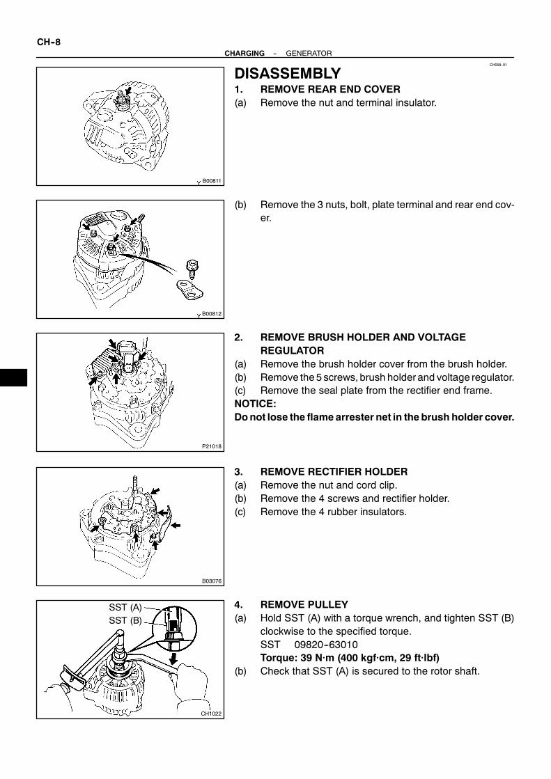
CH058--01
B00811
B00812
P21018
B03076
CH1022
SST (A)SST (B)
CH--8--CHARGING GENERATOR
DISASSEMBLY1. REMOVE REAR END COVER(a) Remove the nut and terminal insulator.
(b) Remove the 3 nuts, bolt, plate terminal and rear end cov-er.
2. REMOVE BRUSH HOLDER AND VOLTAGEREGULATOR
(a) Remove the brush holder cover from the brush holder.(b) Remove the5 screws, brush holderand voltage regulator.(c) Remove the seal plate from the rectifier end frame.NOTICE:Donot lose the flame arrester net in the brush holder cover.
3. REMOVE RECTIFIER HOLDER(a) Remove the nut and cord clip.(b) Remove the 4 screws and rectifier holder.(c) Remove the 4 rubber insulators.
4. REMOVE PULLEY(a) Hold SST (A) with a torque wrench, and tighten SST (B)
clockwise to the specified torque.SST 09820--63010Torque: 39 N·m (400 kgf·cm, 29 ft·lbf)
(b) Check that SST (A) is secured to the rotor shaft.

Z00040
SST (C)
B00814
P21008
SST
--CHARGING GENERATORCH--9
(c) As shown in the illustration, mount SST (C) in a vise, andinstall the generator to SST (C).
(d) To loosen the pulley nut, turn SST (A) in the directionshown in the illustration.
NOTICE:To prevent damage to the rotor shaft, do not loosen thepulley nut more than one--half of a turn.(e) Remove the generator from SST (C).(f) Turn SST (B), and remove SST (A and B).(g) Remove the pulley nut and pulley.5. REMOVE RECTIFIER END FRAME(a) Remove the 3 nuts and cord clip.
(b) Using SST, remove the rectifier end frame.SST 09286--46011
(c) Remove the generator washer.6. REMOVE ROTOR FROM DRIVE END FRAME

CH059--01
CH0784
Ohmmeter
Continuity
B02105
Ohmmeter
No Continuity
CH1023
CH0806
Ohmmeter
Continuity
CH0803
Ohmmeter
No Continuity
CH--10--CHARGING GENERATOR
INSPECTION1. INSPECT ROTOR FOR OPEN CIRCUITUsing an ohmmeter, check that there is continuity between theslip rings.
Standard resistance:2.1 -- 2.5 Ω at 20˚C (68˚F)
If there is no continuity, replace the rotor.
2. INSPECT ROTOR FOR GROUNDUsing an ohmmeter, check that there is no continuity betweenthe slip ring and rotor.If there is continuity, replace the rotor.
3. INSPECT SLIP RINGS(a) Check that the slip rings are not rough or scored.If rough or scored, replace the rotor.(b) Using vernier calipers, measure the slip ring diameter.
Standard diameter:14.2 -- 14.4 mm (0.559 -- 0.567 in.)Minimum diameter:12.8 mm (0.504 in.)
If the diameter is less than minimum, replace the rotor.
4. INSPECT STATOR FOR OPEN CIRCUITUsing an ohmmeter, check that there is continuity between thecoil leads.If there is no continuity, replace the drive end frame assembly.
5. INSPECT STATOR FOR GROUNDUsing an ohmmeter, check that there is no continuity betweenthe coil lead and drive end frame.If there is continuity, replace the drive end frame assembly.

P13535
Length
P08486
OhmmeterPositive (+)Terminal
RectifierTerminal
P08487
Ohmmeter
Negative (--)Terminal
--CHARGING GENERATORCH--11
6. INSPECT EXPOSED BRUSH LENGTHUsing vernier calipers, measure the exposed brush length.
Standard exposed length:10.5 mm (0.413 in.)Minimum exposed length:1.5 mm (0.059 in.)
If the exposed length is less than minimum, replace the brushholder.
7. INSPECT POSITIVE RECTIFIER(a) Using an ohmmeter, connect one tester probe to the posi-
tive (+) terminal and the other to each rectifier terminal.(b) Reverse the polarity of the tester probes and repeat step
(a).(c) Check that one shows continuity and the other shows no
continuity.If continuity is not as specified, replace the rectifier holder.
8. INSPECT NEGATIVE RECTIFIER(a) Using an ohmmeter, connect one tester probe to each
negative (--) terminal and the other to each rectifier termi-nal.
(b) Reverse the polarity of the tester probes and repeat step(a).
(c) Check that one shows continuity and the other shows nocontinuity.
If continuity is not as specified, replace the rectifier holder.9. INSPECT FRONT AND REAR BEARINGCheck that the bearing is not rough or worn.If necessary, replace the bearing.

CH05A--01
CH1024
P21009
SST
P21010
SST
N00581
SST
P13567
CH--12--CHARGING GENERATOR
REPLACEMENT1. REPLACE FRONT BEARING(a) Remove the 4 screws and bearing retainer.
(b) Using SST and a press, press out the bearing.SST 09950--60010 (09951--00260, 09952--06010)
(c) Using SST and a press, press in a new bearing.SST 09950--60010 (09951--00500)
(d) Install the bearing retainer with the 4 screws.Torque: 3.0 N·m (31 kgf·cm, 27 in.·lbf)
2. REPLACE REAR BEARING(a) Using SST, remove the bearing cover (outside) and bear-
ing.SST 09820--00021
NOTICE:Be careful not to damage the fan.(b) Remove the bearing cover (inside).
(c) Place the bearing cover (inside) on the rotor.

N00578
SST
P00074
SST
--CHARGING GENERATORCH--13
(d) Using SST and a press, press in a new bearing.SST 09820--00030
(e) Using SST, push in the bearing cover (outside).SST 09285--76010

CH05B--01
N00556
Pulley
CH1030
P21011
29 mmSocketWrench
B00814
CH1022
SST (A)
SST (B)
CH--14--CHARGING GENERATOR
REASSEMBLY1. PLACE DRIVE END FRAME ON PULLEY2. INSTALL ROTOR TO DRIVE END FRAME
3. INSTALL RECTIFIER END FRAME(a) Place the generator washer on the rotor.
(b) Using a 29 mm socket wrench and press, slowly press inthe rectifier end frame.
(c) Temporarily install the cord clip and 3 nuts.
4. INSTALL PULLEY(a) Install the pulley to the rotor shaft by tightening the pulley
nut by hand.(b) Hold SST (A) with a torque wrench, and tighten SST (B)
clockwise to the specified torque.SST 09820--63010Torque: 39 N·m (400 kgf·cm, 29 ft·lbf)
(c) Check that SST (A) is secured to the pulley shaft.

Z00045
SST (C)
B00815
B00816
Push
B00817
A
A B
B
P21019
--CHARGING GENERATORCH--15
(d) As shown in the illustration, mount SST (C) in a vise, andinstall the generator to SST (C).
(e) To torque the pulley nut, turn SST (A) in the directionshown in the illustration.Torque: 110.5 N·m (1,128 kgf·cm, 81 ft·lbf)
(f) Remove the generator from SST (C).(g) Turn SST (B), and remove SST (A and B).
5. INSTALL RECTIFIER HOLDER(a) Install the 4 rubber insulators on the lead wires.
(b) Install the rectifier holder while pushing it with the 4screws.Torque: 2.94 N·m (30 kgf·cm, 26 in.·lbf)
(c) Install the cord clip and nut.Tighten the 4 nuts.Torque:A: 4.5 N·m (46 kgf·cm, 40 in.·lbf)B: 5.4 N·m (55 kgf·cm, 48 in.·lbf)
6. INSTALL VOLTAGE REGULATOR AND BRUSHHOLDER
(a) Place the seal plate on the rectifier end frame.

P21280
Upward
M21017
B00812
B00811
CH--16--CHARGING GENERATOR
(b) Place the voltage regulator and brush holder on the recti-fier end frame.
NOTICE:Be careful of the holder installation direction.(c) Install the 5 screws.
Torque: 2.0 N·m (20 kgf·cm, 18 in.·lbf)
(d) Place the brush holder cover on the brush holder.(e) Check the flame arrester net for whether losing or no.NOTICE:Do not lose the flame arrester net.
7. INSTALL REAR END COVER(a) Install the end cover andplate terminalwith the 3 nuts and
bolt.Torque:Bolt: 3.8 N·m (39 kgf·cm, 34 in.·lbf)Nut: 4.4 N·m (45 kgf·cm, 39 in.·lbf)
(b) Install the terminal insulator with the nut.Torque: 6.5 N·m (66 kgf·cm, 58 in.·lbf)
8. CHECK THAT ROTOR ROTATES SMOOTHLY
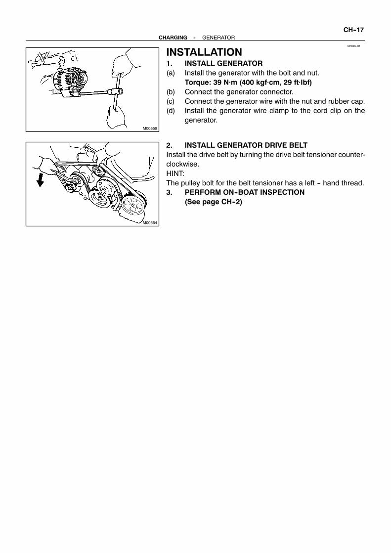
CH05C--01
M00559
M00554
--CHARGING GENERATORCH--17
INSTALLATION1. INSTALL GENERATOR(a) Install the generator with the bolt and nut.
Torque: 39 N·m (400 kgf·cm, 29 ft·lbf)(b) Connect the generator connector.(c) Connect the generator wire with the nut and rubber cap.(d) Install the generator wire clamp to the cord clip on the
generator.
2. INSTALL GENERATOR DRIVE BELTInstall the drive belt by turning the drive belt tensioner counter-clockwise.HINT:The pulley bolt for the belt tensioner has a left -- hand thread.3. PERFORM ON--BOAT INSPECTION
(See page CH--2)

CHARGING
CHARGING SYSTEM CH--1. . . . . . . . . . . . . . . . . . . .
GENERATOR CH--5. . . . . . . . . . . . . . . . . . . . . . . . . . . .

ID--1
ALPHABETICAL INDEX
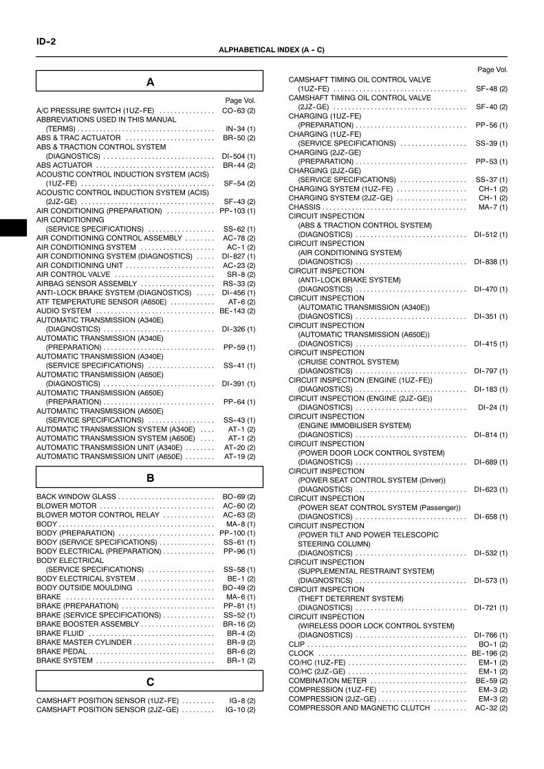
ID--2ALPHABETICAL INDEX (A -- C)
A
Page Vol.A/C PRESSURE SWITCH (1UZ--FE) CO--63 (2). . . . . . . . . . . . . . .ABBREVIATIONS USED IN THIS MANUAL
(TERMS) IN--34 (1). . . . . . . . . . . . . . . . . . . . . . . . . . . . . . . . . . . . .ABS & TRAC ACTUATOR BR--50 (2). . . . . . . . . . . . . . . . . . . . . . . .ABS & TRACTION CONTROL SYSTEM
(DIAGNOSTICS) DI--504 (1). . . . . . . . . . . . . . . . . . . . . . . . . . . . . .ABS ACTUATOR BR--44 (2). . . . . . . . . . . . . . . . . . . . . . . . . . . . . . . .ACOUSTIC CONTROL INDUCTION SYSTEM (ACIS)
(1UZ--FE) SF--54 (2). . . . . . . . . . . . . . . . . . . . . . . . . . . . . . . . . . . .ACOUSTIC CONTROL INDUCTION SYSTEM (ACIS)
(2JZ--GE) SF--43 (2). . . . . . . . . . . . . . . . . . . . . . . . . . . . . . . . . . . .AIR CONDITIONING (PREPARATION) PP--103 (1). . . . . . . . . . . . .AIR CONDITIONING
(SERVICE SPECIFICATIONS) SS--62 (1). . . . . . . . . . . . . . . . . .AIR CONDITIONING CONTROL ASSEMBLY AC--78 (2). . . . . . . .AIR CONDITIONING SYSTEM AC--1 (2). . . . . . . . . . . . . . . . . . . .AIR CONDITIONING SYSTEM (DIAGNOSTICS) DI--827 (1). . . . .AIR CONDITIONING UNIT AC--23 (2). . . . . . . . . . . . . . . . . . . . . . . .AIR CONTROL VALVE SR--8 (2). . . . . . . . . . . . . . . . . . . . . . . . . . .AIRBAG SENSOR ASSEMBLY RS--33 (2). . . . . . . . . . . . . . . . . . . .ANTI--LOCK BRAKE SYSTEM (DIAGNOSTICS) DI--456 (1). . . . .ATF TEMPERATURE SENSOR (A650E) AT--6 (2). . . . . . . . . . . .AUDIO SYSTEM BE--143 (2). . . . . . . . . . . . . . . . . . . . . . . . . . . . . . . .AUTOMATIC TRANSMISSION (A340E)
(DIAGNOSTICS) DI--326 (1). . . . . . . . . . . . . . . . . . . . . . . . . . . . . .AUTOMATIC TRANSMISSION (A340E)
(PREPARATION) PP--59 (1). . . . . . . . . . . . . . . . . . . . . . . . . . . . . .AUTOMATIC TRANSMISSION (A340E)
(SERVICE SPECIFICATIONS) SS--41 (1). . . . . . . . . . . . . . . . . .AUTOMATIC TRANSMISSION (A650E)
(DIAGNOSTICS) DI--391 (1). . . . . . . . . . . . . . . . . . . . . . . . . . . . . .AUTOMATIC TRANSMISSION (A650E)
(PREPARATION) PP--64 (1). . . . . . . . . . . . . . . . . . . . . . . . . . . . . .AUTOMATIC TRANSMISSION (A650E)
(SERVICE SPECIFICATIONS) SS--43 (1). . . . . . . . . . . . . . . . . .AUTOMATIC TRANSMISSION SYSTEM (A340E) AT--1 (2). . . .AUTOMATIC TRANSMISSION SYSTEM (A650E) AT--1 (2). . . .AUTOMATIC TRANSMISSION UNIT (A340E) AT--20 (2). . . . . . . .AUTOMATIC TRANSMISSION UNIT (A650E) AT--19 (2). . . . . . . .
B
BACK WINDOW GLASS BO--69 (2). . . . . . . . . . . . . . . . . . . . . . . . . .BLOWER MOTOR AC--60 (2). . . . . . . . . . . . . . . . . . . . . . . . . . . . . . .BLOWER MOTOR CONTROL RELAY AC--63 (2). . . . . . . . . . . . . .BODY MA--8 (1). . . . . . . . . . . . . . . . . . . . . . . . . . . . . . . . . . . . . . . . . .BODY (PREPARATION) PP--100 (1). . . . . . . . . . . . . . . . . . . . . . . . . .BODY (SERVICE SPECIFICATIONS) SS--61 (1). . . . . . . . . . . . . . .BODY ELECTRICAL (PREPARATION) PP--96 (1). . . . . . . . . . . . . .BODY ELECTRICAL
(SERVICE SPECIFICATIONS) SS--58 (1). . . . . . . . . . . . . . . . . .BODY ELECTRICAL SYSTEM BE--1 (2). . . . . . . . . . . . . . . . . . . . .BODY OUTSIDE MOULDING BO--49 (2). . . . . . . . . . . . . . . . . . . . .BRAKE MA--6 (1). . . . . . . . . . . . . . . . . . . . . . . . . . . . . . . . . . . . . . . .BRAKE (PREPARATION) PP--81 (1). . . . . . . . . . . . . . . . . . . . . . . . .BRAKE (SERVICE SPECIFICATIONS) SS--52 (1). . . . . . . . . . . . . .BRAKE BOOSTER ASSEMBLY BR--16 (2). . . . . . . . . . . . . . . . . . . .BRAKE FLUID BR--4 (2). . . . . . . . . . . . . . . . . . . . . . . . . . . . . . . . . .BRAKE MASTER CYLINDER BR--9 (2). . . . . . . . . . . . . . . . . . . . . .BRAKE PEDAL BR--6 (2). . . . . . . . . . . . . . . . . . . . . . . . . . . . . . . . . .BRAKE SYSTEM BR--1 (2). . . . . . . . . . . . . . . . . . . . . . . . . . . . . . . .
C
CAMSHAFT POSITION SENSOR (1UZ--FE) IG--8 (2). . . . . . . . .CAMSHAFT POSITION SENSOR (2JZ--GE) IG--10 (2). . . . . . . . .
Page Vol.CAMSHAFT TIMING OIL CONTROL VALVE
(1UZ--FE) SF--48 (2). . . . . . . . . . . . . . . . . . . . . . . . . . . . . . . . . . . .CAMSHAFT TIMING OIL CONTROL VALVE
(2JZ--GE) SF--40 (2). . . . . . . . . . . . . . . . . . . . . . . . . . . . . . . . . . . .CHARGING (1UZ--FE)
(PREPARATION) PP--56 (1). . . . . . . . . . . . . . . . . . . . . . . . . . . . . .CHARGING (1UZ--FE)
(SERVICE SPECIFICATIONS) SS--39 (1). . . . . . . . . . . . . . . . . .CHARGING (2JZ--GE)
(PREPARATION) PP--53 (1). . . . . . . . . . . . . . . . . . . . . . . . . . . . . .CHARGING (2JZ--GE)
(SERVICE SPECIFICATIONS) SS--37 (1). . . . . . . . . . . . . . . . . .CHARGING SYSTEM (1UZ--FE) CH--1 (2). . . . . . . . . . . . . . . . . . .CHARGING SYSTEM (2JZ--GE) CH--1 (2). . . . . . . . . . . . . . . . . . .CHASSIS MA--7 (1). . . . . . . . . . . . . . . . . . . . . . . . . . . . . . . . . . . . . . .CIRCUIT INSPECTION
(ABS & TRACTION CONTROL SYSTEM)(DIAGNOSTICS) DI--512 (1). . . . . . . . . . . . . . . . . . . . . . . . . . . . . .
CIRCUIT INSPECTION(AIR CONDITIONING SYSTEM)(DIAGNOSTICS) DI--838 (1). . . . . . . . . . . . . . . . . . . . . . . . . . . . . .
CIRCUIT INSPECTION(ANTI--LOCK BRAKE SYSTEM)(DIAGNOSTICS) DI--470 (1). . . . . . . . . . . . . . . . . . . . . . . . . . . . . .
CIRCUIT INSPECTION(AUTOMATIC TRANSMISSION (A340E))(DIAGNOSTICS) DI--351 (1). . . . . . . . . . . . . . . . . . . . . . . . . . . . . .
CIRCUIT INSPECTION(AUTOMATIC TRANSMISSION (A650E))(DIAGNOSTICS) DI--415 (1). . . . . . . . . . . . . . . . . . . . . . . . . . . . . .
CIRCUIT INSPECTION(CRUISE CONTROL SYSTEM)(DIAGNOSTICS) DI--797 (1). . . . . . . . . . . . . . . . . . . . . . . . . . . . . .
CIRCUIT INSPECTION (ENGINE (1UZ--FE))(DIAGNOSTICS) DI--183 (1). . . . . . . . . . . . . . . . . . . . . . . . . . . . . .
CIRCUIT INSPECTION (ENGINE (2JZ--GE))(DIAGNOSTICS) DI--24 (1). . . . . . . . . . . . . . . . . . . . . . . . . . . . . .
CIRCUIT INSPECTION(ENGINE IMMOBILISER SYSTEM)(DIAGNOSTICS) DI--814 (1). . . . . . . . . . . . . . . . . . . . . . . . . . . . . .
CIRCUIT INSPECTION(POWER DOOR LOCK CONTROL SYSTEM)(DIAGNOSTICS) DI--689 (1). . . . . . . . . . . . . . . . . . . . . . . . . . . . . .
CIRCUIT INSPECTION(POWER SEAT CONTROL SYSTEM (Driver))(DIAGNOSTICS) DI--623 (1). . . . . . . . . . . . . . . . . . . . . . . . . . . . . .
CIRCUIT INSPECTION(POWER SEAT CONTROL SYSTEM (Passenger))(DIAGNOSTICS) DI--658 (1). . . . . . . . . . . . . . . . . . . . . . . . . . . . . .
CIRCUIT INSPECTION(POWER TILT AND POWER TELESCOPICSTEERING COLUMN)(DIAGNOSTICS) DI--532 (1). . . . . . . . . . . . . . . . . . . . . . . . . . . . . .
CIRCUIT INSPECTION(SUPPLEMENTAL RESTRAINT SYSTEM)(DIAGNOSTICS) DI--573 (1). . . . . . . . . . . . . . . . . . . . . . . . . . . . . .
CIRCUIT INSPECTION(THEFT DETERRENT SYSTEM)(DIAGNOSTICS) DI--721 (1). . . . . . . . . . . . . . . . . . . . . . . . . . . . . .
CIRCUIT INSPECTION(WIRELESS DOOR LOCK CONTROL SYSTEM)(DIAGNOSTICS) DI--766 (1). . . . . . . . . . . . . . . . . . . . . . . . . . . . . .
CLIP BO--1 (2). . . . . . . . . . . . . . . . . . . . . . . . . . . . . . . . . . . . . . . . . . .CLOCK BE--196 (2). . . . . . . . . . . . . . . . . . . . . . . . . . . . . . . . . . . . . . . .CO/HC (1UZ--FE) EM--1 (2). . . . . . . . . . . . . . . . . . . . . . . . . . . . . . . .CO/HC (2JZ--GE) EM--1 (2). . . . . . . . . . . . . . . . . . . . . . . . . . . . . . . .COMBINATION METER BE--59 (2). . . . . . . . . . . . . . . . . . . . . . . . . .COMPRESSION (1UZ--FE) EM--3 (2). . . . . . . . . . . . . . . . . . . . . . .COMPRESSION (2JZ--GE) EM--3 (2). . . . . . . . . . . . . . . . . . . . . . . .COMPRESSOR AND MAGNETIC CLUTCH AC--32 (2). . . . . . . . .

ID--3ALPHABETICAL INDEX (C -- E)
Page Vol.CONDENSER AC--44 (2). . . . . . . . . . . . . . . . . . . . . . . . . . . . . . . . . . .COOLANT (1UZ--FE) CO--1 (2). . . . . . . . . . . . . . . . . . . . . . . . . . . . .COOLANT (2JZ--GE) CO--1 (2). . . . . . . . . . . . . . . . . . . . . . . . . . . . .COOLING (1UZ--FE)
(PREPARATION) PP--27 (1). . . . . . . . . . . . . . . . . . . . . . . . . . . . . .COOLING (1UZ--FE)
(SERVICE SPECIFICATIONS) SS--23 (1). . . . . . . . . . . . . . . . . .COOLING (2JZ--GE)
(PREPARATION) PP--23 (1). . . . . . . . . . . . . . . . . . . . . . . . . . . . . .COOLING (2JZ--GE)
(SERVICE SPECIFICATIONS) SS--21 (1). . . . . . . . . . . . . . . . . .COOLING FAN ECU (1UZ--FE) CO--59 (2). . . . . . . . . . . . . . . . . . . .CRANKSHAFT POSITION SENSOR (1UZ--FE) IG--11 (2). . . . . .CRANKSHAFT POSITION SENSOR (2JZ--GE) IG--13 (2). . . . . .CRUISE CONTROL SYSTEM (DIAGNOSTICS) DI--785 (1). . . . . .CUSTOMER PROBLEM ANALYSIS CHECK
(ABS & TRACTION CONTROL SYSTEM)(DIAGNOSTICS) DI--505 (1). . . . . . . . . . . . . . . . . . . . . . . . . . . . . .
CUSTOMER PROBLEM ANALYSIS CHECK(AIR CONDITIONING SYSTEM)(DIAGNOSTICS) DI--828 (1). . . . . . . . . . . . . . . . . . . . . . . . . . . . . .
CUSTOMER PROBLEM ANALYSIS CHECK(ANTI--LOCK BRAKE SYSTEM)(DIAGNOSTICS) DI--457 (1). . . . . . . . . . . . . . . . . . . . . . . . . . . . . .
CUSTOMER PROBLEM ANALYSIS CHECK(AUTOMATIC TRANSMISSION (A340E))(DIAGNOSTICS) DI--327 (1). . . . . . . . . . . . . . . . . . . . . . . . . . . . . .
CUSTOMER PROBLEM ANALYSIS CHECK(AUTOMATIC TRANSMISSION (A650E))(DIAGNOSTICS) DI--392 (1). . . . . . . . . . . . . . . . . . . . . . . . . . . . . .
CUSTOMER PROBLEM ANALYSIS CHECK(CRUISE CONTROL SYSTEM)(DIAGNOSTICS) DI--786 (1). . . . . . . . . . . . . . . . . . . . . . . . . . . . . .
CUSTOMER PROBLEM ANALYSIS CHECK(ENGINE (1UZ--FE))(DIAGNOSTICS) DI--160 (1). . . . . . . . . . . . . . . . . . . . . . . . . . . . . .
CUSTOMER PROBLEM ANALYSIS CHECK(ENGINE (2JZ--GE))(DIAGNOSTICS) DI--2 (1). . . . . . . . . . . . . . . . . . . . . . . . . . . . . .
CUSTOMER PROBLEM ANALYSIS CHECK(ENGINE IMMOBILISER SYSTEM)(DIAGNOSTICS) DI--805 (1). . . . . . . . . . . . . . . . . . . . . . . . . . . . . .
CUSTOMER PROBLEM ANALYSIS CHECK(POWER DOOR LOCK CONTROL SYSTEM)(DIAGNOSTICS) DI--684 (1). . . . . . . . . . . . . . . . . . . . . . . . . . . . . .
CUSTOMER PROBLEM ANALYSIS CHECK(POWER SEAT CONTROL SYSTEM (Driver))(DIAGNOSTICS) DI--618 (1). . . . . . . . . . . . . . . . . . . . . . . . . . . . . .
CUSTOMER PROBLEM ANALYSIS CHECK(POWER SEAT CONTROL SYSTEM (Passenger))(DIAGNOSTICS) DI--653 (1). . . . . . . . . . . . . . . . . . . . . . . . . . . . . .
CUSTOMER PROBLEM ANALYSIS CHECK(POWER TILT AND POWER TELESCOPICSTEERING COLUMN)(DIAGNOSTICS) DI--527 (1). . . . . . . . . . . . . . . . . . . . . . . . . . . . . .
CUSTOMER PROBLEM ANALYSIS CHECK(SUPPLEMENTAL RESTRAINT SYSTEM)(DIAGNOSTICS) DI--565 (1). . . . . . . . . . . . . . . . . . . . . . . . . . . . . .
CUSTOMER PROBLEM ANALYSIS CHECK(THEFT DETERRENT SYSTEM)(DIAGNOSTICS) DI--714 (1). . . . . . . . . . . . . . . . . . . . . . . . . . . . . .
CUSTOMER PROBLEM ANALYSIS CHECK(WIRELESS DOOR LOCK CONTROL SYSTEM)(DIAGNOSTICS) DI--749 (1). . . . . . . . . . . . . . . . . . . . . . . . . . . . . .
CYLINDER BLOCK (1UZ--FE) EM--84 (2). . . . . . . . . . . . . . . . . . . . .CYLINDER BLOCK (2JZ--GE) EM--67 (2). . . . . . . . . . . . . . . . . . . . .CYLINDER HEAD (1UZ--FE) EM--25 (2). . . . . . . . . . . . . . . . . . . . . .CYLINDER HEAD (2JZ--GE) EM--27 (2). . . . . . . . . . . . . . . . . . . . . .
D
Page Vol.DEFOGGER SYSTEM BE--104 (2). . . . . . . . . . . . . . . . . . . . . . . . . . .DIAGNOSTIC TROUBLE CODE CHART
(ABS & TRACTION CONTROL SYSTEM)(DIAGNOSTICS) DI--508 (1). . . . . . . . . . . . . . . . . . . . . . . . . . . . . .
DIAGNOSTIC TROUBLE CODE CHART(AIR CONDITIONING SYSTEM)(DIAGNOSTICS) DI--832 (1). . . . . . . . . . . . . . . . . . . . . . . . . . . . . .
DIAGNOSTIC TROUBLE CODE CHART(ANTI--LOCK BRAKE SYSTEM)(DIAGNOSTICS) DI--463 (1). . . . . . . . . . . . . . . . . . . . . . . . . . . . . .
DIAGNOSTIC TROUBLE CODE CHART(AUTOMATIC TRANSMISSION (A340E))(DIAGNOSTICS) DI--342 (1). . . . . . . . . . . . . . . . . . . . . . . . . . . . . .
DIAGNOSTIC TROUBLE CODE CHART(AUTOMATIC TRANSMISSION (A650E))(DIAGNOSTICS) DI--405 (1). . . . . . . . . . . . . . . . . . . . . . . . . . . . . .
DIAGNOSTIC TROUBLE CODE CHART(CRUISE CONTROL SYSTEM)(DIAGNOSTICS) DI--792 (1). . . . . . . . . . . . . . . . . . . . . . . . . . . . . .
DIAGNOSTIC TROUBLE CODE CHART(ENGINE (1UZ--FE))(DIAGNOSTICS) DI--172 (1). . . . . . . . . . . . . . . . . . . . . . . . . . . . . .
DIAGNOSTIC TROUBLE CODE CHART(ENGINE (2JZ--GE))(DIAGNOSTICS) DI--14 (1). . . . . . . . . . . . . . . . . . . . . . . . . . . . . .
DIAGNOSTIC TROUBLE CODE CHART(ENGINE IMMOBILISER SYSTEM)(DIAGNOSTICS) DI--809 (1). . . . . . . . . . . . . . . . . . . . . . . . . . . . . .
DIAGNOSTIC TROUBLE CODE CHART(SUPPLEMENTAL RESTRAINT SYSTEM)(DIAGNOSTICS) DI--569 (1). . . . . . . . . . . . . . . . . . . . . . . . . . . . . .
DIFFERENTIAL MOUNTING CUSHION SA--82 (2). . . . . . . . . . . . .DRIVE BELT AC--15 (2). . . . . . . . . . . . . . . . . . . . . . . . . . . . . . . . . . . .DRIVE BELT SR--3 (2). . . . . . . . . . . . . . . . . . . . . . . . . . . . . . . . . . . .
E
EFI MAIN RELAY (1UZ--FE) SF--63 (2). . . . . . . . . . . . . . . . . . . . . . .EFI MAIN RELAY (2JZ--GE) SF--48 (2). . . . . . . . . . . . . . . . . . . . . . .ELECTRIC TENSION REDUCER SYSTEM BE--101 (2). . . . . . . . . .ELECTRO CHROMIC MIRROR SYSTEM BE--134 (2). . . . . . . . . . .ELECTRONICALLY CONTROLLED HYDRAULIC
COOLING FAN SYSTEM (1UZ--FE) CO--28 (2). . . . . . . . . . . . . .EMISSION CONTROL (1UZ--FE)
(PREPARATION) PP--15 (1). . . . . . . . . . . . . . . . . . . . . . . . . . . . . .EMISSION CONTROL (1UZ--FE)
(SERVICE SPECIFICATIONS) SS--16 (1). . . . . . . . . . . . . . . . . .EMISSION CONTROL (2JZ--GE)
(PREPARATION) PP--14 (1). . . . . . . . . . . . . . . . . . . . . . . . . . . . . .EMISSION CONTROL (2JZ--GE)
(SERVICE SPECIFICATIONS) SS--15 (1). . . . . . . . . . . . . . . . . .EMISSION CONTROL SYSTEM (1UZ--FE) EC--1 (2). . . . . . . . . .EMISSION CONTROL SYSTEM (2JZ--GE) EC--1 (2). . . . . . . . . .ENGINE MA--5 (1). . . . . . . . . . . . . . . . . . . . . . . . . . . . . . . . . . . . . . . .ENGINE (1UZ--FE)
(DIAGNOSTICS) DI--159 (1). . . . . . . . . . . . . . . . . . . . . . . . . . . . . .ENGINE (2JZ--GE)
(DIAGNOSTICS) DI--1 (1). . . . . . . . . . . . . . . . . . . . . . . . . . . . . .ENGINE CONTROL MODULE (ECM)
(1UZ--FE) SF--87 (2). . . . . . . . . . . . . . . . . . . . . . . . . . . . . . . . . . . .ENGINE CONTROL MODULE (ECM)
(2JZ--GE) SF--66 (2). . . . . . . . . . . . . . . . . . . . . . . . . . . . . . . . . . . .ENGINE COOLANT TEMPERATURE (ECT) SENSOR
(1UZ--FE) CO--61 (2). . . . . . . . . . . . . . . . . . . . . . . . . . . . . . . . . . . .ENGINE COOLANT TEMPERATURE (ECT) SENSOR
(1UZ--FE) SF--72 (2). . . . . . . . . . . . . . . . . . . . . . . . . . . . . . . . . . . .

ID--4ALPHABETICAL INDEX (E -- H)
Page Vol.ENGINE COOLANT TEMPERATURE (ECT) SENSOR
(2JZ--GE) SF--55 (2). . . . . . . . . . . . . . . . . . . . . . . . . . . . . . . . . . . .ENGINE IMMOBILISER SYSTEM BE--206 (2). . . . . . . . . . . . . . . . . .ENGINE IMMOBILISER SYSTEM
(DIAGNOSTICS) DI--804 (1). . . . . . . . . . . . . . . . . . . . . . . . . . . . . .ENGINE MECHANICAL (1UZ--FE)
(PREPARATION) PP--8 (1). . . . . . . . . . . . . . . . . . . . . . . . . . . . . .ENGINE MECHANICAL (1UZ--FE)
(SERVICE SPECIFICATIONS) SS--9 (1). . . . . . . . . . . . . . . . . .ENGINE MECHANICAL (2JZ--GE)
(PREPARATION) PP--2 (1). . . . . . . . . . . . . . . . . . . . . . . . . . . . . .ENGINE MECHANICAL (2JZ--GE)
(SERVICE SPECIFICATIONS) SS--4 (1). . . . . . . . . . . . . . . . . .ENGINE UNIT (1UZ--FE) EM--69 (2). . . . . . . . . . . . . . . . . . . . . . . . . .ENGINE UNIT (2JZ--GE) EM--55 (2). . . . . . . . . . . . . . . . . . . . . . . . . .EVAPORATIVE EMISSION (EVAP) CONTROL SYSTEM
(1UZ--FE) EC--5 (2). . . . . . . . . . . . . . . . . . . . . . . . . . . . . . . . . . . .EVAPORATIVE EMISSION (EVAP) CONTROL SYSTEM
(2JZ--GE) EC--5 (2). . . . . . . . . . . . . . . . . . . . . . . . . . . . . . . . . . . .EVAPORATOR AC--47 (2). . . . . . . . . . . . . . . . . . . . . . . . . . . . . . . . . .EXHAUST SYSTEM (1UZ--FE) EM--113 (2). . . . . . . . . . . . . . . . . . . .EXHAUST SYSTEM (2JZ--GE) EM--90 (2). . . . . . . . . . . . . . . . . . . .EXPANSION VALVE AC--54 (2). . . . . . . . . . . . . . . . . . . . . . . . . . . . .EXTENSION HOUSING OIL SEAL (A340E) AT--3 (2). . . . . . . . .EXTENSION HOUSING OIL SEAL (A650E) AT--3 (2). . . . . . . . .
F
FLOOR CARPET BO--95 (2). . . . . . . . . . . . . . . . . . . . . . . . . . . . . . . .FOG LIGHT SYSTEM BE--37 (2). . . . . . . . . . . . . . . . . . . . . . . . . . . .FOR ALL OF VEHICLES IN--10 (1). . . . . . . . . . . . . . . . . . . . . . . . . .FRONT AXLE HUB SA--11 (2). . . . . . . . . . . . . . . . . . . . . . . . . . . . . .FRONT BRAKE CALIPER BR--23 (2). . . . . . . . . . . . . . . . . . . . . . . .FRONT BRAKE PAD BR--20 (2). . . . . . . . . . . . . . . . . . . . . . . . . . . . .FRONT BUMPER BO--4 (2). . . . . . . . . . . . . . . . . . . . . . . . . . . . . . . .FRONT DOOR BO--23 (2). . . . . . . . . . . . . . . . . . . . . . . . . . . . . . . . . .FRONT LOWER SUSPENSION ARM SA--32 (2). . . . . . . . . . . . . . .FRONT PASSENGER AIRBAG ASSEMBLY RS--21 (2). . . . . . . . .FRONT SEAT BO--102 (2). . . . . . . . . . . . . . . . . . . . . . . . . . . . . . . . . . .FRONT SHOCK ABSORBER SA--19 (2). . . . . . . . . . . . . . . . . . . . . .FRONT SPEED SENSOR BR--56 (2). . . . . . . . . . . . . . . . . . . . . . . .FRONT STABILIZER BAR SA--37 (2). . . . . . . . . . . . . . . . . . . . . . . .FRONT UPPER SUSPENSION ARM SA--27 (2). . . . . . . . . . . . . . .FRONT WHEEL ALIGNMENT SA--4 (2). . . . . . . . . . . . . . . . . . . . .FRONT WHEEL HUB BOLT SA--18 (2). . . . . . . . . . . . . . . . . . . . . . .FUEL CUT RPM (1UZ--FE) SF--89 (2). . . . . . . . . . . . . . . . . . . . . . . .FUEL CUT RPM (2JZ--GE) SF--68 (2). . . . . . . . . . . . . . . . . . . . . . . .FUEL LID BO--45 (2). . . . . . . . . . . . . . . . . . . . . . . . . . . . . . . . . . . . . . .FUEL LID OPENER SYSTEM BE--141 (2). . . . . . . . . . . . . . . . . . . . .FUEL PRESSURE PULSATION DAMPER
(1UZ--FE) SF--28 (2). . . . . . . . . . . . . . . . . . . . . . . . . . . . . . . . . . . .FUEL PRESSURE PULSATION DAMPER
(2JZ--GE) SF--25 (2). . . . . . . . . . . . . . . . . . . . . . . . . . . . . . . . . . . .FUEL PRESSURE REGULATOR (1UZ--FE) SF--13 (2). . . . . . . . .FUEL PRESSURE REGULATOR (2JZ--GE) SF--14 (2). . . . . . . . .FUEL PUMP (1UZ--FE) SF--5 (2). . . . . . . . . . . . . . . . . . . . . . . . . . .FUEL PUMP (2JZ--GE) SF--5 (2). . . . . . . . . . . . . . . . . . . . . . . . . . .FUEL PUMP ECU (1UZ--FE) SF--85 (2). . . . . . . . . . . . . . . . . . . . . .FUEL PUMP ECU (2JZ--GE) SF--64 (2). . . . . . . . . . . . . . . . . . . . . .FUEL TANK AND LINE (1UZ--FE) SF--31 (2). . . . . . . . . . . . . . . . . .FUEL TANK AND LINE (2JZ--GE) SF--28 (2). . . . . . . . . . . . . . . . . .
G
GARAGE DOOR OPENER SYSTEM BE--198 (2). . . . . . . . . . . . . . .GENERAL INFORMATION
(FOR ALL OF VEHICLES) IN--10 (1). . . . . . . . . . . . . . . . . . . . . .
Page Vol.GENERAL INFORMATION
(HOW TO TROUBLESHOOT ECUCONTROLLED SYSTEMS) IN--18 (1). . . . . . . . . . . . . . . . . . . . .
GENERAL INFORMATION(HOW TO USE THIS MANUAL) IN--1 (1). . . . . . . . . . . . . . . . .
GENERAL INFORMATION(REPAIR INSTRUCTIONS) IN--4 (1). . . . . . . . . . . . . . . . . . . . .
GENERATOR (1UZ--FE) CH--5 (2). . . . . . . . . . . . . . . . . . . . . . . . . .GENERATOR (2JZ--GE) CH--6 (2). . . . . . . . . . . . . . . . . . . . . . . . . .GLOSSARY OF SAE AND LEXUS TERMS
(TERMS) IN--36 (1). . . . . . . . . . . . . . . . . . . . . . . . . . . . . . . . . . . . .
H
HEADLIGHT AND TAILLIGHT SYSTEM BE--24 (2). . . . . . . . . . . . .HEATED OXYGEN SENSOR (1UZ--FE) SF--79 (2). . . . . . . . . . . . .HEATED OXYGEN SENSOR (2JZ--GE) SF--60 (2). . . . . . . . . . . . .HEATER RADIATOR AC--51 (2). . . . . . . . . . . . . . . . . . . . . . . . . . . . .HOOD BO--15 (2). . . . . . . . . . . . . . . . . . . . . . . . . . . . . . . . . . . . . . . . .HOOD LOCK CONTROL BO--19 (2). . . . . . . . . . . . . . . . . . . . . . . . .HOOD SUPPORT BO--18 (2). . . . . . . . . . . . . . . . . . . . . . . . . . . . . . .HORN SYSTEM BE--216 (2). . . . . . . . . . . . . . . . . . . . . . . . . . . . . . . . .HOW TO PROCEED WITH TROUBLESHOOTING
(ABS & TRACTION CONTROL SYSTEM)(DIAGNOSTICS) DI--504 (1). . . . . . . . . . . . . . . . . . . . . . . . . . . . . .
HOW TO PROCEED WITH TROUBLESHOOTING(AIR CONDITIONING SYSTEM)(DIAGNOSTICS) DI--827 (1). . . . . . . . . . . . . . . . . . . . . . . . . . . . . .
HOW TO PROCEED WITH TROUBLESHOOTING(ANTI--LOCK BRAKE SYSTEM)(DIAGNOSTICS) DI--456 (1). . . . . . . . . . . . . . . . . . . . . . . . . . . . . .
HOW TO PROCEED WITH TROUBLESHOOTING(AUTOMATIC TRANSMISSION (A340E))(DIAGNOSTICS) DI--326 (1). . . . . . . . . . . . . . . . . . . . . . . . . . . . . .
HOW TO PROCEED WITH TROUBLESHOOTING(AUTOMATIC TRANSMISSION (A650E))(DIAGNOSTICS) DI--391 (1). . . . . . . . . . . . . . . . . . . . . . . . . . . . . .
HOW TO PROCEED WITH TROUBLESHOOTING(CRUISE CONTROL SYSTEM)(DIAGNOSTICS) DI--785 (1). . . . . . . . . . . . . . . . . . . . . . . . . . . . . .
HOW TO PROCEED WITH TROUBLESHOOTING(ENGINE (1UZ--FE))(DIAGNOSTICS) DI--159 (1). . . . . . . . . . . . . . . . . . . . . . . . . . . . . .
HOW TO PROCEED WITH TROUBLESHOOTING(ENGINE (2JZ--GE))(DIAGNOSTICS) DI--1 (1). . . . . . . . . . . . . . . . . . . . . . . . . . . . . .
HOW TO PROCEED WITH TROUBLESHOOTING(ENGINE IMMOBILISER SYSTEM)(DIAGNOSTICS) DI--804 (1). . . . . . . . . . . . . . . . . . . . . . . . . . . . . .
HOW TO PROCEED WITH TROUBLESHOOTING(HOW TO TROUBLESHOOT ECUCONTROLLED SYSTEMS) IN--19 (1). . . . . . . . . . . . . . . . . . . . .
HOW TO PROCEED WITH TROUBLESHOOTING(POWER DOOR LOCK CONTROL SYSTEM)(DIAGNOSTICS) DI--683 (1). . . . . . . . . . . . . . . . . . . . . . . . . . . . . .
HOW TO PROCEED WITH TROUBLESHOOTING(POWER SEAT CONTROL SYSTEM (Driver))(DIAGNOSTICS) DI--617 (1). . . . . . . . . . . . . . . . . . . . . . . . . . . . . .
HOW TO PROCEED WITH TROUBLESHOOTING(POWER SEAT CONTROL SYSTEM (Passenger))(DIAGNOSTICS) DI--652 (1). . . . . . . . . . . . . . . . . . . . . . . . . . . . . .
HOW TO PROCEED WITH TROUBLESHOOTING(POWER TILT AND POWER TELESCOPICSTEERING COLUMN)(DIAGNOSTICS) DI--526 (1). . . . . . . . . . . . . . . . . . . . . . . . . . . . . .
HOW TO PROCEED WITH TROUBLESHOOTING(SUPPLEMENTAL RESTRAINT SYSTEM)(DIAGNOSTICS) DI--564 (1). . . . . . . . . . . . . . . . . . . . . . . . . . . . . .

ID--5ALPHABETICAL INDEX (H -- P)
Page Vol.HOW TO PROCEED WITH TROUBLESHOOTING
(THEFT DETERRENT SYSTEM)(DIAGNOSTICS) DI--713 (1). . . . . . . . . . . . . . . . . . . . . . . . . . . . . .
HOW TO PROCEED WITH TROUBLESHOOTING(WIRELESS DOOR LOCK CONTROL SYSTEM)(DIAGNOSTICS) DI--748 (1). . . . . . . . . . . . . . . . . . . . . . . . . . . . . .
HOW TO TROUBLESHOOT ECU CONTROLLEDSYSTEMS IN--18 (1). . . . . . . . . . . . . . . . . . . . . . . . . . . . . . . . . . .
HOW TO USE THE DIAGNOSTIC CHART ANDINSPECTION PROCEDURE(HOW TO TROUBLESHOOT ECUCONTROLLED SYSTEMS) IN--29 (1). . . . . . . . . . . . . . . . . . . . .
HOW TO USE THIS MANUAL IN--1 (1). . . . . . . . . . . . . . . . . . . . .HYDRAULIC MOTOR (1UZ--FE) CO--44 (2). . . . . . . . . . . . . . . . . . .HYDRAULIC PUMP (1UZ--FE) CO--31 (2). . . . . . . . . . . . . . . . . . . . .
I
IDENTIFICATION INFORMATION IN--3 (1). . . . . . . . . . . . . . . . . .IDLE SPEED (1UZ--FE) EM--10 (2). . . . . . . . . . . . . . . . . . . . . . . . . . .IDLE SPEED (2JZ--GE) EM--12 (2). . . . . . . . . . . . . . . . . . . . . . . . . . .IGNITION (1UZ--FE)
(PREPARATION) PP--45 (1). . . . . . . . . . . . . . . . . . . . . . . . . . . . . .IGNITION (1UZ--FE)
(SERVICE SPECIFICATIONS) SS--31 (1). . . . . . . . . . . . . . . . . .IGNITION (2JZ--GE)
(PREPARATION) PP--43 (1). . . . . . . . . . . . . . . . . . . . . . . . . . . . . .IGNITION (2JZ--GE)
(SERVICE SPECIFICATIONS) SS--29 (1). . . . . . . . . . . . . . . . . .IGNITION COIL (1UZ--FE) IG--5 (2). . . . . . . . . . . . . . . . . . . . . . . .IGNITION COIL (2JZ--GE) IG--6 (2). . . . . . . . . . . . . . . . . . . . . . . .IGNITION SWITCH AND KEY UNLOCK WARNING
SWITCH BE--21 (2). . . . . . . . . . . . . . . . . . . . . . . . . . . . . . . . . . . . .IGNITION SYSTEM (1UZ--FE) IG--1 (2). . . . . . . . . . . . . . . . . . . . .IGNITION SYSTEM (2JZ--GE) IG--1 (2). . . . . . . . . . . . . . . . . . . . .IGNITION TIMING (1UZ--FE) EM--9 (2). . . . . . . . . . . . . . . . . . . . . .IGNITION TIMING (2JZ--GE) EM--11 (2). . . . . . . . . . . . . . . . . . . . . .ILLUMINATION LIGHT SYSTEM BE--43 (2). . . . . . . . . . . . . . . . . . .INJECTOR (1UZ--FE) SF--19 (2). . . . . . . . . . . . . . . . . . . . . . . . . . . .INJECTOR (2JZ--GE) SF--19 (2). . . . . . . . . . . . . . . . . . . . . . . . . . . .INSIDE VEHICLE MA--2 (1). . . . . . . . . . . . . . . . . . . . . . . . . . . . . . . .INSTRUMENT PANEL BO--85 (2). . . . . . . . . . . . . . . . . . . . . . . . . . . .INTERIOR LIGHT SYSTEM BE--46 (2). . . . . . . . . . . . . . . . . . . . . . .
J
JOINT ANGLE PR--17 (2). . . . . . . . . . . . . . . . . . . . . . . . . . . . . . . . . .
K
KNOCK SENSOR (1UZ--FE) SF--76 (2). . . . . . . . . . . . . . . . . . . . . .KNOCK SENSOR (2JZ--GE) SF--58 (2). . . . . . . . . . . . . . . . . . . . . .
L
LUBRICATION (1UZ--FE)(PREPARATION) PP--38 (1). . . . . . . . . . . . . . . . . . . . . . . . . . . . . .
LUBRICATION (1UZ--FE)(SERVICE SPECIFICATIONS) SS--27 (1). . . . . . . . . . . . . . . . . .
LUBRICATION (2JZ--GE)(PREPARATION) PP--33 (1). . . . . . . . . . . . . . . . . . . . . . . . . . . . . .
LUBRICATION (2JZ--GE)(SERVICE SPECIFICATIONS) SS--25 (1). . . . . . . . . . . . . . . . . .
LUGGAGE COMPARTMENT DOOR AND HINGE BO--36 (2). . . .
M
MAINTENANCE (PREPARATION) PP--1 (1). . . . . . . . . . . . . . . . .
Page Vol.MAINTENANCE (SERVICE SPECIFICATIONS) SS--3 (1). . . . . .MANIFOLD GAUGE SET AC--18 (2). . . . . . . . . . . . . . . . . . . . . . . . .MANUAL TILT AND MANUAL TELESCOPIC
STEERING COLUMN SR--10 (2). . . . . . . . . . . . . . . . . . . . . . . . . .MASS AIR FLOW (MAF) METER (1UZ--FE) SF--33 (2). . . . . . . . . .MASS AIR FLOW (MAF) METER (2JZ--GE) SF--30 (2). . . . . . . . . .
O
O/D DIRECT CLUTCH SPEED SENSOR (A340E) AT--8 (2). . . .OIL AND FILTER (1UZ--FE) LU--1 (2). . . . . . . . . . . . . . . . . . . . . . .OIL AND FILTER (2JZ--GE) LU--1 (2). . . . . . . . . . . . . . . . . . . . . . .OIL COOLER (1UZ--FE) CO--55 (2). . . . . . . . . . . . . . . . . . . . . . . . . .OIL PUMP (1UZ--FE) LU--4 (2). . . . . . . . . . . . . . . . . . . . . . . . . . . . .OIL PUMP (2JZ--GE) LU--4 (2). . . . . . . . . . . . . . . . . . . . . . . . . . . . .OUTSIDE REAR VIEW MIRROR BO--34 (2). . . . . . . . . . . . . . . . . . .OUTSIDE VEHICLE MA--1 (1). . . . . . . . . . . . . . . . . . . . . . . . . . . . . .
P
PARK/NEUTRAL POSITION (PNP) SWITCH(A340E) AT--9 (2). . . . . . . . . . . . . . . . . . . . . . . . . . . . . . . . . . . . . .
PARK/NEUTRAL POSITION (PNP) SWITCH(A650E) AT--9 (2). . . . . . . . . . . . . . . . . . . . . . . . . . . . . . . . . . . . . .
PARKING BRAKE BR--39 (2). . . . . . . . . . . . . . . . . . . . . . . . . . . . . . .PARKING BRAKE LEVER BR--8 (2). . . . . . . . . . . . . . . . . . . . . . . .PARKING LOCK PAWL (A340E) AT--16 (2). . . . . . . . . . . . . . . . . . .PARTS LAYOUT AND SCHEMATIC DRAWING
(1UZ--FE) EC--2 (2). . . . . . . . . . . . . . . . . . . . . . . . . . . . . . . . . . . .PARTS LAYOUT AND SCHEMATIC DRAWING
(2JZ--GE) EC--2 (2). . . . . . . . . . . . . . . . . . . . . . . . . . . . . . . . . . . .PARTS LOCATION
(ABS & TRACTION CONTROL SYSTEM)(DIAGNOSTICS) DI--509 (1). . . . . . . . . . . . . . . . . . . . . . . . . . . . . .
PARTS LOCATION (ANTI--LOCK BRAKE SYSTEM)(DIAGNOSTICS) DI--465 (1). . . . . . . . . . . . . . . . . . . . . . . . . . . . . .
PARTS LOCATION(AUTOMATIC TRANSMISSION (A340E))(DIAGNOSTICS) DI--343 (1). . . . . . . . . . . . . . . . . . . . . . . . . . . . . .
PARTS LOCATION(AUTOMATIC TRANSMISSION (A650E))(DIAGNOSTICS) DI--407 (1). . . . . . . . . . . . . . . . . . . . . . . . . . . . . .
PARTS LOCATION (CRUISE CONTROL SYSTEM)(DIAGNOSTICS) DI--793 (1). . . . . . . . . . . . . . . . . . . . . . . . . . . . . .
PARTS LOCATION (ENGINE (1UZ--FE))(DIAGNOSTICS) DI--178 (1). . . . . . . . . . . . . . . . . . . . . . . . . . . . . .
PARTS LOCATION (ENGINE (2JZ--GE))(DIAGNOSTICS) DI--19 (1). . . . . . . . . . . . . . . . . . . . . . . . . . . . . .
PARTS LOCATION(ENGINE IMMOBILISER SYSTEM)(DIAGNOSTICS) DI--810 (1). . . . . . . . . . . . . . . . . . . . . . . . . . . . . .
PARTS LOCATION(POWER DOOR LOCK CONTROL SYSTEM)(DIAGNOSTICS) DI--685 (1). . . . . . . . . . . . . . . . . . . . . . . . . . . . . .
PARTS LOCATION(POWER SEAT CONTROL SYSTEM (Driver))(DIAGNOSTICS) DI--619 (1). . . . . . . . . . . . . . . . . . . . . . . . . . . . . .
PARTS LOCATION(POWER SEAT CONTROL SYSTEM (Passenger))(DIAGNOSTICS) DI--654 (1). . . . . . . . . . . . . . . . . . . . . . . . . . . . . .
PARTS LOCATION(POWER TILT AND POWER TELESCOPICSTEERING COLUMN)(DIAGNOSTICS) DI--528 (1). . . . . . . . . . . . . . . . . . . . . . . . . . . . . .
PARTS LOCATION(SUPPLEMENTAL RESTRAINT SYSTEM)(DIAGNOSTICS) DI--570 (1). . . . . . . . . . . . . . . . . . . . . . . . . . . . . .
PARTS LOCATION (THEFT DETERRENT SYSTEM)(DIAGNOSTICS) DI--717 (1). . . . . . . . . . . . . . . . . . . . . . . . . . . . . .

ID--6ALPHABETICAL INDEX (P -- R)
Page Vol.PARTS LOCATION
(WIRELESS DOOR LOCK CONTROL SYSTEM)(DIAGNOSTICS) DI--763 (1). . . . . . . . . . . . . . . . . . . . . . . . . . . . . .
POSITIVE CRANKCASE VENTILATION (PCV) SYSTEM(1UZ--FE) EC--4 (2). . . . . . . . . . . . . . . . . . . . . . . . . . . . . . . . . . . .
POSITIVE CRANKCASE VENTILATION (PCV) SYSTEM(2JZ--GE) EC--4 (2). . . . . . . . . . . . . . . . . . . . . . . . . . . . . . . . . . . .
POWER DOOR LOCK CONTROL SYSTEM(DIAGNOSTICS) DI--683 (1). . . . . . . . . . . . . . . . . . . . . . . . . . . . . .
POWER MIRROR CONTROL SYSTEM BE--128 (2). . . . . . . . . . . . .POWER SEAT CONTROL SYSTEM (Driver)
(DIAGNOSTICS) DI--617 (1). . . . . . . . . . . . . . . . . . . . . . . . . . . . . .POWER SEAT CONTROL SYSTEM (Passenger)
(DIAGNOSTICS) DI--652 (1). . . . . . . . . . . . . . . . . . . . . . . . . . . . . .POWER SEAT CONTROL SYSTEM
(w/o Driving Position Memory) BE--120 (2). . . . . . . . . . . . . . . . . . .POWER SOURCE BE--13 (2). . . . . . . . . . . . . . . . . . . . . . . . . . . . . . .POWER STEERING FLUID SR--4 (2). . . . . . . . . . . . . . . . . . . . . . .POWER STEERING GEAR SR--59 (2). . . . . . . . . . . . . . . . . . . . . . .POWER STEERING VANE PUMP (1UZ--FE) SR--46 (2). . . . . . . .POWER STEERING VANE PUMP (2JZ--GE) SR--35 (2). . . . . . . .POWER TILT AND POWER TELESCOPIC
STEERING COLUMN SR--25 (2). . . . . . . . . . . . . . . . . . . . . . . . . .POWER TILT AND POWER TELESCOPIC
STEERING COLUMN (DIAGNOSTICS) DI--526 (1). . . . . . . . . .POWER WINDOW CONTROL SYSTEM BE--108 (2). . . . . . . . . . . .PRE--CHECK
(ABS & TRACTION CONTROL SYSTEM)(DIAGNOSTICS) DI--506 (1). . . . . . . . . . . . . . . . . . . . . . . . . . . . . .
PRE--CHECK (AIR CONDITIONING SYSTEM)(DIAGNOSTICS) DI--829 (1). . . . . . . . . . . . . . . . . . . . . . . . . . . . . .
PRE--CHECK (ANTI--LOCK BRAKE SYSTEM)(DIAGNOSTICS) DI--458 (1). . . . . . . . . . . . . . . . . . . . . . . . . . . . . .
PRE--CHECK(AUTOMATIC TRANSMISSION (A340E))(DIAGNOSTICS) DI--328 (1). . . . . . . . . . . . . . . . . . . . . . . . . . . . . .
PRE--CHECK(AUTOMATIC TRANSMISSION (A650E))(DIAGNOSTICS) DI--393 (1). . . . . . . . . . . . . . . . . . . . . . . . . . . . . .
PRE--CHECK (CRUISE CONTROL SYSTEM)(DIAGNOSTICS) DI--787 (1). . . . . . . . . . . . . . . . . . . . . . . . . . . . . .
PRE--CHECK (ENGINE (1UZ--FE))(DIAGNOSTICS) DI--161 (1). . . . . . . . . . . . . . . . . . . . . . . . . . . . . .
PRE--CHECK (ENGINE (2JZ--GE))(DIAGNOSTICS) DI--3 (1). . . . . . . . . . . . . . . . . . . . . . . . . . . . . .
PRE--CHECK (ENGINE IMMOBILISER SYSTEM)(DIAGNOSTICS) DI--806 (1). . . . . . . . . . . . . . . . . . . . . . . . . . . . . .
PRE--CHECK(SUPPLEMENTAL RESTRAINT SYSTEM)(DIAGNOSTICS) DI--566 (1). . . . . . . . . . . . . . . . . . . . . . . . . . . . . .
PRE--CHECK (THEFT DETERRENT SYSTEM)(DIAGNOSTICS) DI--715 (1). . . . . . . . . . . . . . . . . . . . . . . . . . . . . .
PRE--CHECK(WIRELESS DOOR LOCK CONTROL SYSTEM)(DIAGNOSTICS) DI--750 (1). . . . . . . . . . . . . . . . . . . . . . . . . . . . . .
PRESSURE SWITCH AC--74 (2). . . . . . . . . . . . . . . . . . . . . . . . . . . .PROBLEM SYMPTOMS TABLE
(ABS & TRACTION CONTROL SYSTEM)(DIAGNOSTICS) DI--511 (1). . . . . . . . . . . . . . . . . . . . . . . . . . . . . .
PROBLEM SYMPTOMS TABLE(AIR CONDITIONING SYSTEM)(DIAGNOSTICS) DI--836 (1). . . . . . . . . . . . . . . . . . . . . . . . . . . . . .
PROBLEM SYMPTOMS TABLE(ANTI--LOCK BRAKE SYSTEM)(DIAGNOSTICS) DI--469 (1). . . . . . . . . . . . . . . . . . . . . . . . . . . . . .
PROBLEM SYMPTOMS TABLE(AUTOMATIC TRANSMISSION (A340E))(DIAGNOSTICS) DI--346 (1). . . . . . . . . . . . . . . . . . . . . . . . . . . . . .
Page Vol.PROBLEM SYMPTOMS TABLE
(AUTOMATIC TRANSMISSION (A650E))(DIAGNOSTICS) DI--410 (1). . . . . . . . . . . . . . . . . . . . . . . . . . . . . .
PROBLEM SYMPTOMS TABLE(CRUISE CONTROL SYSTEM)(DIAGNOSTICS) DI--796 (1). . . . . . . . . . . . . . . . . . . . . . . . . . . . . .
PROBLEM SYMPTOMS TABLE (ENGINE (1UZ--FE))(DIAGNOSTICS) DI--182 (1). . . . . . . . . . . . . . . . . . . . . . . . . . . . . .
PROBLEM SYMPTOMS TABLE (ENGINE (2JZ--GE))(DIAGNOSTICS) DI--23 (1). . . . . . . . . . . . . . . . . . . . . . . . . . . . . .
PROBLEM SYMPTOMS TABLE(ENGINE IMMOBILISER SYSTEM)(DIAGNOSTICS) DI--813 (1). . . . . . . . . . . . . . . . . . . . . . . . . . . . . .
PROBLEM SYMPTOMS TABLE(POWER DOOR LOCK CONTROL SYSTEM)(DIAGNOSTICS) DI--688 (1). . . . . . . . . . . . . . . . . . . . . . . . . . . . . .
PROBLEM SYMPTOMS TABLE(POWER SEAT CONTROL SYSTEM (Driver))(DIAGNOSTICS) DI--622 (1). . . . . . . . . . . . . . . . . . . . . . . . . . . . . .
PROBLEM SYMPTOMS TABLE(POWER SEAT CONTROL SYSTEM (Passenger))(DIAGNOSTICS) DI--657 (1). . . . . . . . . . . . . . . . . . . . . . . . . . . . . .
PROBLEM SYMPTOMS TABLE(POWER TILT AND POWER TELESCOPICSTEERING COLUMN)(DIAGNOSTICS) DI--531 (1). . . . . . . . . . . . . . . . . . . . . . . . . . . . . .
PROBLEM SYMPTOMS TABLE(SUPPLEMENTAL RESTRAINT SYSTEM)(DIAGNOSTICS) DI--572 (1). . . . . . . . . . . . . . . . . . . . . . . . . . . . . .
PROBLEM SYMPTOMS TABLE(THEFT DETERRENT SYSTEM)(DIAGNOSTICS) DI--720 (1). . . . . . . . . . . . . . . . . . . . . . . . . . . . . .
PROBLEM SYMPTOMS TABLE(WIRELESS DOOR LOCK CONTROL SYSTEM)(DIAGNOSTICS) DI--765 (1). . . . . . . . . . . . . . . . . . . . . . . . . . . . . .
PROGRESSIVE POWER STEERING (PPS) SR--75 (2). . . . . . . . .PROPELLER SHAFT (PREPARATION) PP--69 (1). . . . . . . . . . . . .PROPELLER SHAFT
(SERVICE SPECIFICATIONS) SS--45 (1). . . . . . . . . . . . . . . . . .PROPELLER SHAFT ASSEMBLY (SC300) PR--2 (2). . . . . . . . . .PROPELLER SHAFT ASSEMBLY (SC400) PR--9 (2). . . . . . . . . .PROPORTIONING AND BY--PASS VALVE
(P & B VALVE) BR--43 (2). . . . . . . . . . . . . . . . . . . . . . . . . . . . . . . .
Q
QUARTER WINDOW GLASS BO--66 (2). . . . . . . . . . . . . . . . . . . . . .
R
RADIATOR (1UZ--FE) CO--15 (2). . . . . . . . . . . . . . . . . . . . . . . . . . . .RADIATOR (2JZ--GE) CO--14 (2). . . . . . . . . . . . . . . . . . . . . . . . . . . .REAR AXLE CARRIER SA--41 (2). . . . . . . . . . . . . . . . . . . . . . . . . . .REAR BRAKE CALIPER BR--33 (2). . . . . . . . . . . . . . . . . . . . . . . . . .REAR BRAKE PAD BR--30 (2). . . . . . . . . . . . . . . . . . . . . . . . . . . . . .REAR BUMPER BO--11 (2). . . . . . . . . . . . . . . . . . . . . . . . . . . . . . . . .REAR DIFFERENTIAL CARRIER SA--61 (2). . . . . . . . . . . . . . . . . .REAR DIFFERENTIAL SIDE GEAR SHAFT
OIL SEAL SA--58 (2). . . . . . . . . . . . . . . . . . . . . . . . . . . . . . . . . . . .REAR DRIVE SHAFT SA--49 (2). . . . . . . . . . . . . . . . . . . . . . . . . . . .REAR LOWER SUSPENSION ARM AND
STRUT ROD SA--94 (2). . . . . . . . . . . . . . . . . . . . . . . . . . . . . . . . .REAR SEAT BO--111 (2). . . . . . . . . . . . . . . . . . . . . . . . . . . . . . . . . . . .REAR SHOCK ABSORBER SA--83 (2). . . . . . . . . . . . . . . . . . . . . . .REAR SPEED SENSOR BR--59 (2). . . . . . . . . . . . . . . . . . . . . . . . . .REAR STABILIZER BAR SA--100 (2). . . . . . . . . . . . . . . . . . . . . . . . . .REAR UPPER SUSPENSION ARM SA--90 (2). . . . . . . . . . . . . . . .REAR WHEEL ALIGNMENT SA--8 (2). . . . . . . . . . . . . . . . . . . . . .REAR WHEEL HUB BOLT SA--48 (2). . . . . . . . . . . . . . . . . . . . . . . .

ID--7ALPHABETICAL INDEX (R -- T)
Page Vol.RECEIVER AC--41 (2). . . . . . . . . . . . . . . . . . . . . . . . . . . . . . . . . . . . .REFRIGERANT LINE AC--20 (2). . . . . . . . . . . . . . . . . . . . . . . . . . . .RELAY AC--77 (2). . . . . . . . . . . . . . . . . . . . . . . . . . . . . . . . . . . . . . . . .REPAIR INSTRUCTIONS IN--4 (1). . . . . . . . . . . . . . . . . . . . . . . . .ROCKER PANEL MOULDING BO--55 (2). . . . . . . . . . . . . . . . . . . . .ROOF HEADLINING BO--98 (2). . . . . . . . . . . . . . . . . . . . . . . . . . . . .
S
SEAT BELT BO--116 (2). . . . . . . . . . . . . . . . . . . . . . . . . . . . . . . . . . . . .SEAT BELT PRETENSIONER BO--119 (2). . . . . . . . . . . . . . . . . . . . .SEAT HEATER SYSTEM BE--137 (2). . . . . . . . . . . . . . . . . . . . . . . . .SENSOR AC--70 (2). . . . . . . . . . . . . . . . . . . . . . . . . . . . . . . . . . . . . . .SENSOR ROTOR (A340E) AT--4 (2). . . . . . . . . . . . . . . . . . . . . . . .SERVOMOTOR AC--66 (2). . . . . . . . . . . . . . . . . . . . . . . . . . . . . . . . .SFI (1UZ--FE)
(PREPARATION) PP--20 (1). . . . . . . . . . . . . . . . . . . . . . . . . . . . . .SFI (1UZ--FE)
(SERVICE SPECIFICATIONS) SS--19 (1). . . . . . . . . . . . . . . . . .SFI (2JZ--GE)
(PREPARATION) PP--16 (1). . . . . . . . . . . . . . . . . . . . . . . . . . . . . .SFI (2JZ--GE)
(SERVICE SPECIFICATIONS) SS--17 (1). . . . . . . . . . . . . . . . . .SFI SYSTEM (1UZ--FE) SF--1 (2). . . . . . . . . . . . . . . . . . . . . . . . . . .SFI SYSTEM (2JZ--GE) SF--1 (2). . . . . . . . . . . . . . . . . . . . . . . . . . .SHIFT LOCK SYSTEM (A340E) AT--17 (2). . . . . . . . . . . . . . . . . . . .SHIFT LOCK SYSTEM (A650E) AT--16 (2). . . . . . . . . . . . . . . . . . . .SLIDING ROOF BO--75 (2). . . . . . . . . . . . . . . . . . . . . . . . . . . . . . . . .SLIDING ROOF SYSTEM BE--116 (2). . . . . . . . . . . . . . . . . . . . . . . . .SPOILER BO--125 (2). . . . . . . . . . . . . . . . . . . . . . . . . . . . . . . . . . . . . . .SRS AIRBAG BO--3 (2). . . . . . . . . . . . . . . . . . . . . . . . . . . . . . . . . . .SRS AIRBAG RS--1 (2). . . . . . . . . . . . . . . . . . . . . . . . . . . . . . . . . . .STANDARD BOLT (SERVICE SPECIFICATIONS) SS--1 (1). . . .STARTER (1UZ--FE) ST--2 (2). . . . . . . . . . . . . . . . . . . . . . . . . . . . .STARTER (2JZ--GE) ST--2 (2). . . . . . . . . . . . . . . . . . . . . . . . . . . . .STARTER RELAY (1UZ--FE) ST--18 (2). . . . . . . . . . . . . . . . . . . . . .STARTER RELAY (2JZ--GE) ST--16 (2). . . . . . . . . . . . . . . . . . . . . .STARTING (1UZ--FE)
(PREPARATION) PP--50 (1). . . . . . . . . . . . . . . . . . . . . . . . . . . . . .STARTING (1UZ--FE)
(SERVICE SPECIFICATIONS) SS--35 (1). . . . . . . . . . . . . . . . . .STARTING (2JZ--GE)
(PREPARATION) PP--47 (1). . . . . . . . . . . . . . . . . . . . . . . . . . . . . .STARTING (2JZ--GE)
(SERVICE SPECIFICATIONS) SS--33 (1). . . . . . . . . . . . . . . . . .STARTING SYSTEM (1UZ--FE) ST--1 (2). . . . . . . . . . . . . . . . . . . .STARTING SYSTEM (2JZ--GE) ST--1 (2). . . . . . . . . . . . . . . . . . . .STEERING (PREPARATION) PP--85 (1). . . . . . . . . . . . . . . . . . . . . .STEERING (SERVICE SPECIFICATIONS) SS--54 (1). . . . . . . . . .STEERING SYSTEM SR--1 (2). . . . . . . . . . . . . . . . . . . . . . . . . . . . .STEERING WHEEL SR--9 (2). . . . . . . . . . . . . . . . . . . . . . . . . . . . . .STEERING WHEEL PAD AND SPIRAL CABLE RS--7 (2). . . . . .STOP LIGHT SYSTEM BE--51 (2). . . . . . . . . . . . . . . . . . . . . . . . . . .SUPPLEMENTAL RESTRAINT SYSTEM
(DIAGNOSTICS) DI--564 (1). . . . . . . . . . . . . . . . . . . . . . . . . . . . . .SUPPLEMENTAL RESTRAINT SYSTEM
(PREPARATION) PP--93 (1). . . . . . . . . . . . . . . . . . . . . . . . . . . . . .SUPPLEMENTAL RESTRAINT SYSTEM
(SERVICE SPECIFICATIONS) SS--57 (1). . . . . . . . . . . . . . . . . .SUSPENSION AND AXLE (PREPARATION) PP--72 (1). . . . . . . . .SUSPENSION AND AXLE
(SERVICE SPECIFICATIONS) SS--47 (1). . . . . . . . . . . . . . . . . .
T
TERMINALS OF ECM(AUTOMATIC TRANSMISSION (A340E))(DIAGNOSTICS) DI--344 (1). . . . . . . . . . . . . . . . . . . . . . . . . . . . . .
Page Vol.TERMINALS OF ECM
(AUTOMATIC TRANSMISSION (A650E))(DIAGNOSTICS) DI--408 (1). . . . . . . . . . . . . . . . . . . . . . . . . . . . . .
TERMINALS OF ECM(CRUISE CONTROL SYSTEM)(DIAGNOSTICS) DI--794 (1). . . . . . . . . . . . . . . . . . . . . . . . . . . . . .
TERMINALS OF ECM (ENGINE (1UZ--FE))(DIAGNOSTICS) DI--179 (1). . . . . . . . . . . . . . . . . . . . . . . . . . . . . .
TERMINALS OF ECM (ENGINE (2JZ--GE))(DIAGNOSTICS) DI--20 (1). . . . . . . . . . . . . . . . . . . . . . . . . . . . . .
TERMINALS OF ECM(ENGINE IMMOBILISER SYSTEM)(DIAGNOSTICS) DI--811 (1). . . . . . . . . . . . . . . . . . . . . . . . . . . . . .
TERMINALS OF ECM(SUPPLEMENTAL RESTRAINT SYSTEM)(DIAGNOSTICS) DI--571 (1). . . . . . . . . . . . . . . . . . . . . . . . . . . . . .
TERMINALS OF ECU(ABS & TRACTION CONTROL SYSTEM)(DIAGNOSTICS) DI--510 (1). . . . . . . . . . . . . . . . . . . . . . . . . . . . . .
TERMINALS OF ECU(AIR CONDITIONING SYSTEM)(DIAGNOSTICS) DI--834 (1). . . . . . . . . . . . . . . . . . . . . . . . . . . . . .
TERMINALS OF ECU(ANTI--LOCK BRAKE SYSTEM)(DIAGNOSTICS) DI--466 (1). . . . . . . . . . . . . . . . . . . . . . . . . . . . . .
TERMINALS OF ECU(POWER DOOR LOCK CONTROL SYSTEM)(DIAGNOSTICS) DI--686 (1). . . . . . . . . . . . . . . . . . . . . . . . . . . . . .
TERMINALS OF ECU(POWER SEAT CONTROL SYSTEM (Driver))(DIAGNOSTICS) DI--620 (1). . . . . . . . . . . . . . . . . . . . . . . . . . . . . .
TERMINALS OF ECU(POWER SEAT CONTROL SYSTEM (Passenger))(DIAGNOSTICS) DI--655 (1). . . . . . . . . . . . . . . . . . . . . . . . . . . . . .
TERMINALS OF ECU(POWER TILT AND POWER TELESCOPICSTEERING COLUMN)(DIAGNOSTICS) DI--529 (1). . . . . . . . . . . . . . . . . . . . . . . . . . . . . .
TERMINALS OF ECU(THEFT DETERRENT SYSTEM)(DIAGNOSTICS) DI--718 (1). . . . . . . . . . . . . . . . . . . . . . . . . . . . . .
TERMINALS OF ECU(WIRELESS DOOR LOCK CONTROL SYSTEM)(DIAGNOSTICS) DI--764 (1). . . . . . . . . . . . . . . . . . . . . . . . . . . . . .
TERMS IN--34 (1). . . . . . . . . . . . . . . . . . . . . . . . . . . . . . . . . . . . . . . .THEFT DETERRENT SYSTEM (DIAGNOSTICS) DI--713 (1). . . . .THERMOSTAT (1UZ--FE) CO--11 (2). . . . . . . . . . . . . . . . . . . . . . . . .THERMOSTAT (2JZ--GE) CO--10 (2). . . . . . . . . . . . . . . . . . . . . . . . .THREE--WAY CATALYTIC CONVERTER (TWC)
SYSTEM (1UZ--FE) EC--7 (2). . . . . . . . . . . . . . . . . . . . . . . . . . . .THREE--WAY CATALYTIC CONVERTER (TWC)
SYSTEM (2JZ--GE) EC--7 (2). . . . . . . . . . . . . . . . . . . . . . . . . . . .THROTTLE BODY (1UZ--FE) SF--37 (2). . . . . . . . . . . . . . . . . . . . . .THROTTLE BODY (2JZ--GE) SF--32 (2). . . . . . . . . . . . . . . . . . . . . .TIMING BELT (1UZ--FE) EM--11 (2). . . . . . . . . . . . . . . . . . . . . . . . . .TIMING BELT (2JZ--GE) EM--13 (2). . . . . . . . . . . . . . . . . . . . . . . . . .TIRE AND WHEEL SA--2 (2). . . . . . . . . . . . . . . . . . . . . . . . . . . . . . .TORQUE CONVERTER CLUTCH AND DRIVE PLATE
(A340E) AT--25 (2). . . . . . . . . . . . . . . . . . . . . . . . . . . . . . . . . . . . . .TORQUE CONVERTER CLUTCH AND DRIVE PLATE
(A650E) AT--26 (2). . . . . . . . . . . . . . . . . . . . . . . . . . . . . . . . . . . . . .TROUBLESHOOTING BR--2 (2). . . . . . . . . . . . . . . . . . . . . . . . . . .TROUBLESHOOTING PR--1 (2). . . . . . . . . . . . . . . . . . . . . . . . . . .TROUBLESHOOTING SA--1 (2). . . . . . . . . . . . . . . . . . . . . . . . . . .TROUBLESHOOTING SR--2 (2). . . . . . . . . . . . . . . . . . . . . . . . . . .TURN SIGNAL AND HAZARD WARNING
SYSTEM BE--39 (2). . . . . . . . . . . . . . . . . . . . . . . . . . . . . . . . . . . . .

ID--8ALPHABETICAL INDEX (U -- W)
U
Page Vol.UNDER HOOD MA--4 (1). . . . . . . . . . . . . . . . . . . . . . . . . . . . . . . . . .
V
VALVE BODY ASSEMBLY (A340E) AT--10 (2). . . . . . . . . . . . . . . . .VALVE BODY ASSEMBLY (A650E) AT--11 (2). . . . . . . . . . . . . . . . .VALVE CLEARANCE (1UZ--FE) EM--4 (2). . . . . . . . . . . . . . . . . . . .VALVE CLEARANCE (2JZ--GE) EM--4 (2). . . . . . . . . . . . . . . . . . . .VAPOR PRESSURE SENSOR (1UZ--FE) SF--75 (2). . . . . . . . . . .VAPOR PRESSURE SENSOR (2JZ--GE) SF--57 (2). . . . . . . . . . .VEHICLE IDENTIFICATION AND ENGINE SERIAL
NUMBER (IDENTIFICATION INFORMATION) IN--3 (1). . . . .VEHICLE LIFT AND SUPPORT LOCATIONS
(REPAIR INSTRUCTIONS) IN--8 (1). . . . . . . . . . . . . . . . . . . . .VEHICLE SPEED SENSOR (A340E) AT--7 (2). . . . . . . . . . . . . . .VEHICLE SPEED SENSOR (A650E) AT--5 (2). . . . . . . . . . . . . . .VSV FOR ACOUSTIC CONTROL INDUCTION
SYSTEM (ACIS)(1UZ--FE) SF--66 (2). . . . . . . . . . . . . . . . . . . . . . . . . . . . . . . . . . . .
VSV FOR ACOUSTIC CONTROL INDUCTIONSYSTEM (ACIS)(2JZ--GE) SF--51 (2). . . . . . . . . . . . . . . . . . . . . . . . . . . . . . . . . . . .
VSV FOR EVAPORATIVE EMISSION (EVAP)(1UZ--FE) SF--64 (2). . . . . . . . . . . . . . . . . . . . . . . . . . . . . . . . . . . .
VSV FOR EVAPORATIVE EMISSION (EVAP)(2JZ--GE) SF--49 (2). . . . . . . . . . . . . . . . . . . . . . . . . . . . . . . . . . . .
VSV FOR VAPOR PRESSURE SENSOR(1UZ--FE) SF--71 (2). . . . . . . . . . . . . . . . . . . . . . . . . . . . . . . . . . . .
VSV FOR VAPOR PRESSURE SENSOR(2JZ--GE) SF--54 (2). . . . . . . . . . . . . . . . . . . . . . . . . . . . . . . . . . . .
VVT SENSOR (1UZ--FE) SF--82 (2). . . . . . . . . . . . . . . . . . . . . . . . . .
W
WATER PUMP (1UZ--FE) CO--3 (2). . . . . . . . . . . . . . . . . . . . . . . . .WATER PUMP (2JZ--GE) CO--3 (2). . . . . . . . . . . . . . . . . . . . . . . . .WATER VALVE AC--57 (2). . . . . . . . . . . . . . . . . . . . . . . . . . . . . . . . . .WHEEL ARCH MOULDING BO--52 (2). . . . . . . . . . . . . . . . . . . . . . .WINDSHIELD BO--58 (2). . . . . . . . . . . . . . . . . . . . . . . . . . . . . . . . . . .WIPER AND WASHER SYSTEM BE--54 (2). . . . . . . . . . . . . . . . . . .WIRE HARNESS AND CONNECTOR RS--38 (2). . . . . . . . . . . . . .WIRELESS DOOR LOCK CONTROL SYSTEM
(DIAGNOSTICS) DI--748 (1). . . . . . . . . . . . . . . . . . . . . . . . . . . . . .

ID--1
ALPHABETICAL INDEX

ID--2ALPHABETICAL INDEX (A -- T)
A
PageABBREVIATIONS USED IN THIS MANUAL IN--24. . . . . . . . . . . . . . .ACOUSTIC CONTROL INDUCTION SYSTEM (ACIS) SF--48. . . . . .
C
CAMSHAFT POSITION SENSOR IG--8. . . . . . . . . . . . . . . . . . . . . . . .CAMSHAFT TIMING OIL CONTROL VALVE SF--42. . . . . . . . . . . . . .CHARGING (PREPARATION) PP--21. . . . . . . . . . . . . . . . . . . . . . . . . .CHARGING (SERVICE SPECIFICATIONS) SS--19. . . . . . . . . . . . . . .CHARGING SYSTEM CH--1. . . . . . . . . . . . . . . . . . . . . . . . . . . . . . . . .CIRCUIT INSPECTION DI--20. . . . . . . . . . . . . . . . . . . . . . . . . . . . . . . .CIRCUIT OPENING RELAY SF--59. . . . . . . . . . . . . . . . . . . . . . . . . . . .COMPRESSION EM--1. . . . . . . . . . . . . . . . . . . . . . . . . . . . . . . . . . . . .COOLING (PREPARATION) PP--9. . . . . . . . . . . . . . . . . . . . . . . . . . . . .COOLING (SERVICE SPECIFICATIONS) SS--11. . . . . . . . . . . . . . . .CRANKSHAFT POSITION SENSOR IG--11. . . . . . . . . . . . . . . . . . . .CUSTOMER PROBLEM ANALYSIS CHECK DI--2. . . . . . . . . . . . . . .CYLINDER BLOCK EM--76. . . . . . . . . . . . . . . . . . . . . . . . . . . . . . . . . .CYLINDER HEAD EM--24. . . . . . . . . . . . . . . . . . . . . . . . . . . . . . . . . . .
D
DIAGNOSTIC TROUBLE CODE CHART DI--13. . . . . . . . . . . . . . . . .
E
EFI MAIN RELAY SF--58. . . . . . . . . . . . . . . . . . . . . . . . . . . . . . . . . . . . .EMISSION CONTROL SYSTEM EC--1. . . . . . . . . . . . . . . . . . . . . . . .ENGINE CONTROL MODULE (ECM) SF--74. . . . . . . . . . . . . . . . . . . .ENGINE COOLANT TEMPERATURE (ECT) SENSOR SF--65. . . . .ENGINE MECHANICAL (PREPARATION) PP--1. . . . . . . . . . . . . . . . .ENGINE MECHANICAL (SERVICE SPECIFICATIONS) SS--3. . . . .ENGINE SERIAL NUMBER IN--3. . . . . . . . . . . . . . . . . . . . . . . . . . . . .ENGINE SLING AND SUPPORT POSITIONS IN--7. . . . . . . . . . . . . .ENGINE UNIT EM--67. . . . . . . . . . . . . . . . . . . . . . . . . . . . . . . . . . . . . . .
F
FUEL CUT RPM SF--76. . . . . . . . . . . . . . . . . . . . . . . . . . . . . . . . . . . . . .FUEL PRESSURE PULSATION DAMPER SF--24. . . . . . . . . . . . . . . .FUEL PRESSURE REGULATOR SF--10. . . . . . . . . . . . . . . . . . . . . . .FUEL PUMP SF--5. . . . . . . . . . . . . . . . . . . . . . . . . . . . . . . . . . . . . . . . . .
G
GENERAL INFORMATION (HOW TO USE THIS MANUAL) IN--1. .GENERAL INFORMATION (REPAIR INSTRUCTIONS) IN--4. . . . . .GENERAL INFORMATION (HOW TO TROUBLESHOOT
ECU CONTROLLED SYSTEMS) IN--8. . . . . . . . . . . . . . . . . . . . . .GENERATOR CH--5. . . . . . . . . . . . . . . . . . . . . . . . . . . . . . . . . . . . . . . .GLOSSARY OF SAE AND TOYOTA TERMS IN--25. . . . . . . . . . . . .
H
HOW TO PROCEED WITH TROUBLESHOOTING(ENGINE)(DIAGNOSTICS) DI--1. . . . . . . . . . . . . . . . . . . . . . . . . . . . . . . . . . . .
HOW TO PROCEED WITH TROUBLESHOOTING(HOW TO TROUBLESHOOT ECU CONTROLLEDSYSTEMS) IN--9. . . . . . . . . . . . . . . . . . . . . . . . . . . . . . . . . . . . . . . .
HOW TO TROUBLESHOOT ECU CONTROLLEDSYSTEMS IN--8. . . . . . . . . . . . . . . . . . . . . . . . . . . . . . . . . . . . . . . . .
HOW TO USE THE DIAGNOSTIC CHART AND INSPECTIONPROCEDURE IN--19. . . . . . . . . . . . . . . . . . . . . . . . . . . . . . . . . . . . .
PageHOW TO USE THIS MANUAL IN--1. . . . . . . . . . . . . . . . . . . . . . . . . . .
I
IDENTIFICATION INFORMATION IN--3. . . . . . . . . . . . . . . . . . . . . . . .IDLE SPEED EM--8. . . . . . . . . . . . . . . . . . . . . . . . . . . . . . . . . . . . . . . . .IGNITION (PREPARATION) PP--16. . . . . . . . . . . . . . . . . . . . . . . . . . . .IGNITION (SERVICE SPECIFICATIONS) SS--15. . . . . . . . . . . . . . . . .IGNITION COIL IG--5. . . . . . . . . . . . . . . . . . . . . . . . . . . . . . . . . . . . . . .IGNITION SYSTEM IG--1. . . . . . . . . . . . . . . . . . . . . . . . . . . . . . . . . . . .IGNITION TIMING EM--7. . . . . . . . . . . . . . . . . . . . . . . . . . . . . . . . . . . .INJECTOR SF--14. . . . . . . . . . . . . . . . . . . . . . . . . . . . . . . . . . . . . . . . . .
K
KNOCK SENSOR SF--68. . . . . . . . . . . . . . . . . . . . . . . . . . . . . . . . . . . .
L
LUBRICATION (PREPARATION) PP--11. . . . . . . . . . . . . . . . . . . . . . . .LUBRICATION (SERVICE SPECIFICATIONS) SS--13. . . . . . . . . . . .
M
MASS AIR FLOW (MAF) METER SF--27. . . . . . . . . . . . . . . . . . . . . . . .
O
OIL AND FILTER LU--1. . . . . . . . . . . . . . . . . . . . . . . . . . . . . . . . . . . . . .OIL PUMP LU--4. . . . . . . . . . . . . . . . . . . . . . . . . . . . . . . . . . . . . . . . . . . .
P
PARTS LOCATION DI--16. . . . . . . . . . . . . . . . . . . . . . . . . . . . . . . . . . .POSITIVE CRANKCASE VENTILATION (PCV) SYSTEM EC--2. . .PRE--CHECK DI--3. . . . . . . . . . . . . . . . . . . . . . . . . . . . . . . . . . . . . . . . .PROBLEM SYMPTOMS TABLE DI--19. . . . . . . . . . . . . . . . . . . . . . . . .
R
REPAIR INSTRUCTIONS IN--4. . . . . . . . . . . . . . . . . . . . . . . . . . . . . . .
S
SEA WATER PUMP CO--13. . . . . . . . . . . . . . . . . . . . . . . . . . . . . . . . . .SFI (PREPARATION) PP--7. . . . . . . . . . . . . . . . . . . . . . . . . . . . . . . . . . .SFI (SERVICE SPECIFICATIONS) SS--9. . . . . . . . . . . . . . . . . . . . . . .SFI SYSTEM SF--1. . . . . . . . . . . . . . . . . . . . . . . . . . . . . . . . . . . . . . . . . .STANDARD BOLT SS--1. . . . . . . . . . . . . . . . . . . . . . . . . . . . . . . . . . . . .STARTER ST--2. . . . . . . . . . . . . . . . . . . . . . . . . . . . . . . . . . . . . . . . . . . .STARTER RELAY ST--18. . . . . . . . . . . . . . . . . . . . . . . . . . . . . . . . . . . .STARTING (PREPARATION) PP--18. . . . . . . . . . . . . . . . . . . . . . . . . . .STARTING (SERVICE SPECIFICATIONS) SS--17. . . . . . . . . . . . . . . .STARTING SYSTEM ST--1. . . . . . . . . . . . . . . . . . . . . . . . . . . . . . . . . . .
T
TERMINALS OF ECM DI--17. . . . . . . . . . . . . . . . . . . . . . . . . . . . . . . . .TERMS IN--24. . . . . . . . . . . . . . . . . . . . . . . . . . . . . . . . . . . . . . . . . . . . .THERMOSTAT CO--9. . . . . . . . . . . . . . . . . . . . . . . . . . . . . . . . . . . . . . .THROTTLE BODY SF--31. . . . . . . . . . . . . . . . . . . . . . . . . . . . . . . . . . . .TIMING BELT EM--9. . . . . . . . . . . . . . . . . . . . . . . . . . . . . . . . . . . . . . . .

ID--3ALPHABETICAL INDEX (V --W)
V
PageVALVE CLEARANCE EM--2. . . . . . . . . . . . . . . . . . . . . . . . . . . . . . . . . .VSV FOR ACOUSTIC CONTROL INDUCTION
SYSTEM (ACIS) SF--60. . . . . . . . . . . . . . . . . . . . . . . . . . . . . . . . . . .VVT SENSOR SF--71. . . . . . . . . . . . . . . . . . . . . . . . . . . . . . . . . . . . . . . .
W
WATER PUMP CO--1. . . . . . . . . . . . . . . . . . . . . . . . . . . . . . . . . . . . . . .

1998 TOYOTAMOTORCORPORATIONAll rights reserved. This book may not be repro-duced or copied, in whole or in part, without thewritten permission of Toyota Motor Corporation.First Printing:
FOREWORD
This manual contains preparation, specifications, diagnostics and repair procedures for the M1UZ engine.
The manual is divided into 13 sections with a thumb index for each section at the edge of the pages.
All information in this manual is based on the latest product information at the time of publication. However,specifications and procedures are subject to change without notice.
TOYOTA MOTOR CORPORATION

CAUTION
Thismanual does not include all the necessary items about repair and service. Thismanual ismadefor the purpose of the use for the persons who have special techniques and certifications. In thecases that non--specialized or uncertified technicians perform repair or service only using thismanu-al or without proper equipment or tool, that may cause severe injury to you or other people aroundand also cause damage to your customer’s engine.
In order to prevent dangerous operation and damages to your customer’s engine, be sure to followthe instruction shown below.
S Must read this manual thoroughly. It is especially important to have good understanding all thecontents written in the PRECAUTION of ”IN” section.
S The servicemethodwritten in thismanual is very effective to perform repair and service.Whenperforming the operations following the procedures using thismanual, be sure to use toolsspe-cified and recommended. If using non--specified or recommended tools and service method,be sure to confirm safety of the technicians and any possibility of causing personal injury ordamage to the customer’s engine before starting the operation.
S If part replacement is necessary,must replace the part with the samepart number or equivalentpart. Do not replace it with inferior quality.
S It is important to note that this manual contains various ”Cautions” and ”Notices” that must becarefully observed in order to reduce the risk of personal injury during service or repair, or thepossibility that improper service or repair may damage the engine or render it unsafe. It is alsoimportant to understand that these ”Cautions” and ”Notices” are not exhaustive, because it isimportant to warn of all the possible hazardous consequences that might result from failure tofollow these instructions.

INTRODUCTIONPREPARATION
SERVICE SPECIFICATIONSDIAGNOSTICS
ENGINE MECHANICALEMISSION CONTROL
SFICOOLING
LUBRICATIONIGNITIONSTARTINGCHARGING
ALPHABETICAL INDEX

SS0HU--01
--SERVICE SPECIFICATIONS ENGINE MECHANICAL1
ENGINE MECHANICALSERVICE DATACompression
pressure
at 250 rpm STD
Minimum
Difference of pressure between each cylinder
1,226 kPa (12.5 kgf/cm2, 178 psi) or more
981 kPa (10.0 kgf/cm2, 142 psi)
98 kPa (1.0 kgf/cm2, 14 psi) or less
Valve
clearance
at cold Intake
Exhaust
Valve clearance adjusting shim No.00
No.02
No.04
No.06
No.08
No.10
No.12
No.14
No.16
No.18
No.20
No.22
No.24
No.26
No.28
No.30
No.32
No.34
No.36
No.38
No.40
No.42
No.44
No.46
No.48
No.50
No.52
No.54
No.56
No.58
No.60
No.62
No.64
No.66
No.68
No.70
No.72
No.74
No.76
No.78
No.80
0.15 -- 0.25 mm (0.006 -- 0.010 in.)
0.25 -- 0.35 mm (0.010 -- 0.014 in.)
2.000 mm (0.0787 in.)
2.020 mm (0.0795 in.)
2.040 mm (0.0803 in.)
2.060 mm (0.0811 in.)
2.080 mm (0.0819 in.)
2.100 mm (0.0827 in.)
2.120 mm (0.0835 in.)
2.140 mm (0.0843 in.)
2.160 mm (0.0850 in.)
2.180 mm (0.0858 in.)
2.200 mm (0.0866 in.)
2.220 mm (0.0874 in.)
2.240 mm (0.0882 in.)
2.260 mm (0.0890 in.)
2.280 mm (0.0898 in.)
2.300 mm (0.0906 in.)
2.320 mm (0.0913 in.)
2.340 mm (0.0921 in.)
2.360 mm (0.0929 in.)
2.380 mm (0.0937 in.)
2.400 mm (0.0945 in.)
2.420 mm (0.0953 in.)
2.440 mm (0.0961 in.)
2.460 mm (0.0969 in.)
2.480 mm (0.0976 in.)
2.500 mm (0.0984 in.)
2.520 mm (0.0992 in.)
2.540 mm (0.1000 in)
2.560 mm (0.1008 in.)
2.580 mm (0.1016 in.)
2.600 mm (0.1024 in.)
2.620 mm (0.1031 in.)
2.640 mm (0.1039 in.)
2.660 mm (0.1047 in.)
2.680 mm (0.1055 in.)
2.700 mm (0.1063 in.)
2.720 mm (0.1071 in.)
2.740 mm (0.1079 in.)
2.760 mm (0.1087 in.)
2.780 mm (0.1094 in.)
2.800 mm (0.1102 in.)
Ignition timing w/ Terminals TC and E1 connected of DLC1 8 --12˚ BTDC @ idle
Idle speed -- 780 ± 50 rpm
Timing belt
tensioner
Protrusion from housing end 10.5 -- 11.5 mm (0.413 -- 0.453 in.)

2--SERVICE SPECIFICATIONS ENGINE MECHANICAL
Cylinder head Warpage Maximum
Valve seat
Refacing angle
Contacting angle
Contacting width
Valve guide bushing bore diameter STD
O/S 0.05
Cylinder head bolt thread inside diameter STD
Minimum
0.10 mm (0.039 in.)
30˚, 45˚, 60˚45˚1.0 -- 1.4 mm (0.039 -- 0.055 in.)
10.285 -- 10.306 mm (0.4049 -- 0.4057 in.)
10.335 -- 10.356 mm (0.4069 -- 0.4077 in.)
9.770 -- 9.960 mm (0.3846 -- 0.3921 in.)
9.60 mm (0.3780 in.)
Valve guide
bushing
Inside diameter
Outside diameter (for repair part) STD
O/S 0.05
5.510 -- 5.530 mm (0.2169 -- 0.2177 in.)
10.333 -- 10.344 mm (0.4068 -- 0.4072 in.)
10.383 -- 10.394 mm (0.4088 -- 0.4092 in.)
Valve Valve overall length STD Intake
Exhaust
Minimum Intake
Exhaust
Valve face angle
Stem diameter Intake
Exhaust
Stem oil clearance STD Intake
Exhaust
Maximum Intake
Exhaust
Margin thickness STD
Minimum
94.80 -- 95.30 mm (3.7323 -- 3.7520 in.)
94.85 -- 95.35 mm (3.7342 -- 3.7539 in.)
94.55 mm (3.7224 in.)
94.60 mm (3.7244 in.)
44.5˚5.470 -- 5.485 mm (0.2154 -- 0.2159 in.)
5.465 -- 5.480 mm (0.2152 -- 0.2157 in.)
0.025 -- 0.060 mm (0.0010 -- 0.0024 in.)
0.030 -- 0.065 mm (0.0012 -- 0.0026 in.)
0.08 mm (0.0031 in.)
0.10 mm (0.0039 in.)
1.0 mm (0.039 in.)
0.5 mm (0.020 in.)
Valve spring Deviation Maximum
Free length
Installed tension at 35.0 mm (1.378 in.)
2.0 mm (0.079 in.)
54.05 -- 54.15 mm (2.1279 -- 2.1319 in.)
204 -- 226 N (20.8 -- 23.0 kgf·cm, 45.9 -- 50.7 lbf)
Valve lifter Lifter diameter
Lifter bore diameter
Oil clearance STD
Maximum
30.966 -- 30.976 mm (1.2191 -- 2.2195 in.)
31.000 -- 31.016 mm (1.2205 -- 1.2211 in.)
0.024 -- 0.050 mm (0.0009 -- 0.0020 in.)
0.07 mm (0.0028 in.)
Camshaft Thrust clearance STD Intake
Exhaust
Maximum Intake
Exhaust
Journal oil clearance STD
Maximum
Journal diameter Intake (A)
Others
Circle runout
Cam lobe height STD Intake
Exhaust
Minimum Intake
Exhaust
Camshaft gear backlash STD
Maximum
Camshaft gear spring end free distance
0.060 -- 0.100 mm (0.0024 -- 0.0039 in.)
0.040 -- 0.090 mm (0.0016 -- 0.0035 in.)
0.13 mm (0.0051 in.)
0.12 mm (0.0047 in.)
0.030 -- 0.067 mm (0.0012 -- 0.0026 in.)
0.10 mm (0.0039 in.)
30.984 -- 31.000 mm (1.2198 -- 1.2205 in.)
26.954 -- 26.970 mm (1.0612 -- 1.0618 in.)
0.08 mm (0.0031 in.)
42.610 -- 42.710 mm (1.6776 -- 1.6815 in.)
42.630 -- 42.730 mm (1.6783 -- 1.6823 in.)
42.46 mm (1.6717 in.)
42.48 mm (1.6724 in.)
0.020 -- 0.200 mm (0.0008 -- 0.0079 in.)
0.30 mm (0.0188 in.)
18.2 -- 18.8 mm (0.712 -- 0.740 in.)
Camshaft timing
tube
Journal diameter Green peinted mark
Red peinted mark
Journal oil clearance Sylinder head mark A
Sylinder head mark B
Maximum
39.958 -- 39.964 mm (1.5731 -- 1.5734 in.)
39.964 -- 39.970 mm (1.5734 -- 1.5736 in.)
0.036 -- 0.050 mm (0.0014 -- 0.0020 in.)
0.038 -- 0.052 mm (0.0015 -- 0.0021 in)
0.085 mm (0.0033 in.)
Manifold Warpage Maximum Intake
Exhaust
0.15 mm (0.0059 in.)
0.50 mm (0.0197 in.)

--SERVICE SPECIFICATIONS ENGINE MECHANICAL3
Cylinder block Cylinder head surface warpage Maximum
Cylinder bore diameter STD Mark 1
Mark 2
Mark 3
Maximum
Main bearing cap bolt tension portion diameter
STD
Minimum
0.07 mm (0.0028 in.)
87.500 -- 87.510 mm (3.4449 -- 3.4453 in.)
87.510 -- 87.520 mm (3.4453 -- 3.4457 in.)
87.520 -- 87.530 mm (3.4457 -- 3.4461 in.)
87.73 mm (3.4539 in.)
7.500 -- 7.600 mm (0.2953 -- 0.2992 in.)
7.20 mm (0.2835 in.)
Piston and
piston ring
Piston diameter STD Mark 1
Mark 2
Mark 3
Piston oil clearance STD
Maximum
Piston ring groove clearance No.1
No.2
Piston ring end gap STD No.1
No.2
Oil
Maximum No.1
No.2
Oil
87.406 -- 87.416 mm (3.4411 -- 3.4416 in.)
87.416 -- 87.426 mm (3.4416 -- 3.4420 in.)
87.426 -- 87.436 mm (3.4420 -- 3.4424 in.)
0.084 -- 0.104 mm (0.0033 -- 0.0041 in.)
0.124 mm (0.0049 in.)
0.020 -- 0.070 mm (0.0008 -- 0.0028 in.)
0.010 -- 0.050 mm (0.0004 -- 0.0020 in.)
0.250 -- 0.450 mm (0.0098 -- 0.0177 in.)
0.500 -- 0.700 mm (0.0197 -- 0.0276 in.)
0.150 -- 0.500 mm (0.0059 -- 0.0197 in.)
1.05 mm (0.0413 in.)
1.30 mm (0.0512 in.)
1.10 mm (0.0433 in.)
Connecting rod Thrust clearance STD
Maximum
Connecting rod thickness
Connecting rod oil clearance STD
Maximum
Connecting rod bearing center wall thickness
(Reference) Mark 2
Mark 3
Mark 4
Mark 5
Mark 6
Mark 7
Rod bend Maximum per 100 mm (3.94 in.)
Rod twist Maximum per 100 mm (3.94 in.)
Bushing inside diameter
Piston pin diameter
Bushing oil clearance STD
Maximum
Connecting rod bolt tension portion diameter STD
Minimum
0.160 -- 0.290 mm (0.0063 -- 0.0138 in.)
0.35 mm (0.0138 in.)
22.880 -- 22.920 mm (0.9008 -- 0.9024 in.)
0.027 -- 0.053 mm (0.0011 -- 0.0021 in.)
0.065 mm (0.0026 in.)
1.484 -- 1.487 mm (0.0584 -- 0.0585 in.)
1.487 -- 1.490 mm (0.0585 -- 0.0587 in.)
1.490 -- 1.493 mm (0.0587 -- 0.0588 in.)
1.493 -- 1.496 mm (0.0588 -- 0.0589 in.)
1.496 -- 1.499 mm (0.0589 -- 0.0590 in.)
1.499 -- 1.502 mm (0.0590 -- 0.0591 in.)
0.05 mm (0.0020 in.)
0.15 mm (0.0059 in.)
22.005 -- 22.014 mm (0.8663 -- 0.8667 in.)
21.997 -- 22.006 mm (0.8660 -- 0.8664 in.)
0.005 -- 0.011 mm (0.0002 -- 0.0004 in)
0.05 mm (0.0020 in.)
7.200 -- 7.300 mm (0.2835 -- 0.2874 in.)
7.00 mm (0.2756 in.)
Crankshaft Thrust clearance STD
Maximum
Thrust washer thickness
Main journal bore diameter on cylinder block
(with main bearing)
Main journal oil clearance STD No.1 and No.5
Others
Maximum No.1 and No.5
Others
Main journal diameter
0.020 -- 0.220 mm (0.0008 -- 0.0087 in.)
0.30 mm (0.0118 in.)
2.440 -- 2.490 mm (0.0961 -- 0.0980 in.)
66.986 -- 67.000 mm (2.6372 -- 2.6378 in.)
0.017 -- 0.033 mm (0.0007 -- 0.0013 in.)
0.029 -- 0.045 mm (0.0011 -- 0.0018 in.)
0.043 mm (0.0017 in.)
0.055 mm (0.0022 in.)
66.988 -- 67.000 mm (2.6373 -- 2.6378 in.)
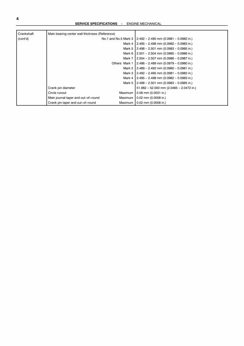
4--SERVICE SPECIFICATIONS ENGINE MECHANICAL
Crankshaft
(cont’d)
Main bearing center wall thickness (Reference)
No.1 and No.5 Mark 3
Mark 4
Mark 5
Mark 6
Mark 7
Others Mark 1
Mark 2
Mark 3
Mark 4
Mark 5
Crank pin diameter
Circle runout Maximum
Main journal taper and out--of--round Maximum
Crank pin taper and out--of--round Maximum
2.492 -- 2.495 mm (0.0981 -- 0.0982 in.)
2.495 -- 2.498 mm (0.0982 -- 0.0983 in.)
2.498 -- 2.501 mm (0.0983 -- 0.0985 in.)
2.501 -- 2.504 mm (0.0985 -- 0.0986 in.)
2.504 -- 2.507 mm (0.0986 -- 0.0987 in.)
2.486 -- 2.489 mm (0.0979 -- 0.0980 in.)
2.489 -- 2.492 mm (0.0980 -- 0.0981 in.)
2.492 -- 2.495 mm (0.0981 -- 0.0982 in.)
2.495 -- 2.498 mm (0.0982 -- 0.0983 in.)
2.498 -- 2.501 mm (0.0983 -- 0.0985 in.)
51.982 -- 52.000 mm (2.0465 -- 2.0472 in.)
0.08 mm (0.0031 in.)
0.02 mm (0.0008 in.)
0.02 mm (0.0008 in.)
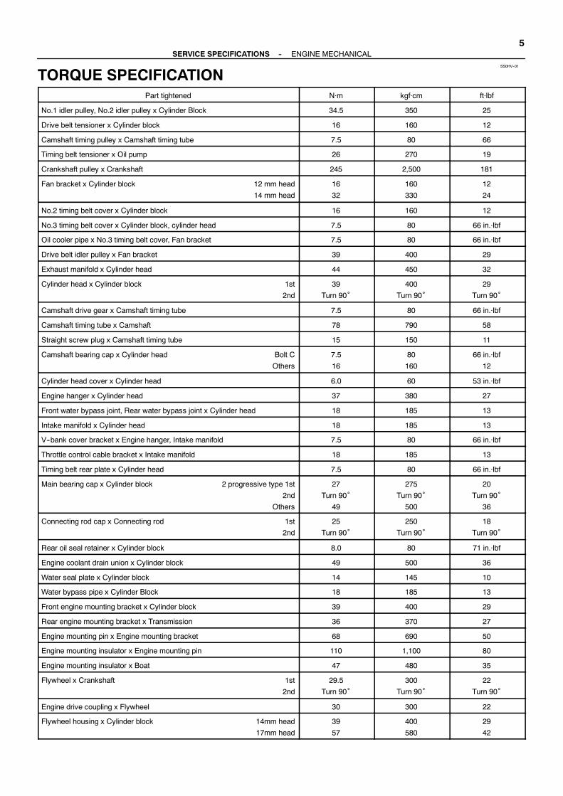
SS0HV--01
--SERVICE SPECIFICATIONS ENGINE MECHANICAL5
TORQUE SPECIFICATIONPart tightened N·m kgf·cm ft·lbf
No.1 idler pulley, No.2 idler pulley x Cylinder Block 34.5 350 25
Drive belt tensioner x Cylinder block 16 160 12
Camshaft timing pulley x Camshaft timing tube 7.5 80 66
Timing belt tensioner x Oil pump 26 270 19
Crankshaft pulley x Crankshaft 245 2,500 181
Fan bracket x Cylinder block 12 mm head
14 mm head
16
32
160
330
12
24
No.2 timing belt cover x Cylinder block 16 160 12
No.3 timing belt cover x Cylinder block, cylinder head 7.5 80 66 in.·lbf
Oil cooler pipe x No.3 timing belt cover, Fan bracket 7.5 80 66 in.·lbf
Drive belt idler pulley x Fan bracket 39 400 29
Exhaust manifold x Cylinder head 44 450 32
Cylinder head x Cylinder block 1st
2nd
39
Turn 90˚400
Turn 90˚29
Turn 90˚
Camshaft drive gear x Camshaft timing tube 7.5 80 66 in.·lbf
Camshaft timing tube x Camshaft 78 790 58
Straight screw plug x Camshaft timing tube 15 150 11
Camshaft bearing cap x Cylinder head Bolt C
Others
7.5
16
80
160
66 in.·lbf
12
Cylinder head cover x Cylinder head 6.0 60 53 in.·lbf
Engine hanger x Cylinder head 37 380 27
Front water bypass joint, Rear water bypass joint x Cylinder head 18 185 13
Intake manifold x Cylinder head 18 185 13
V--bank cover bracket x Engine hanger, Intake manifold 7.5 80 66 in.·lbf
Throttle control cable bracket x Intake manifold 18 185 13
Timing belt rear plate x Cylinder head 7.5 80 66 in.·lbf
Main bearing cap x Cylinder block 2 progressive type 1st
2nd
Others
27
Turn 90˚49
275
Turn 90˚500
20
Turn 90˚36
Connecting rod cap x Connecting rod 1st
2nd
25
Turn 90˚250
Turn 90˚18
Turn 90˚
Rear oil seal retainer x Cylinder block 8.0 80 71 in.·lbf
Engine coolant drain union x Cylinder block 49 500 36
Water seal plate x Cylinder block 14 145 10
Water bypass pipe x Cylinder Block 18 185 13
Front engine mounting bracket x Cylinder block 39 400 29
Rear engine mounting bracket x Transmission 36 370 27
Engine mounting pin x Engine mounting bracket 68 690 50
Engine mounting insulator x Engine mounting pin 110 1,100 80
Engine mounting insulator x Boat 47 480 35
Flywheel x Crankshaft 1st
2nd
29.5
Turn 90˚300
Turn 90˚22
Turn 90˚
Engine drive coupling x Flywheel 30 300 22
Flywheel housing x Cylinder block 14mm head
17mm head
39
57
400
580
29
42

6--SERVICE SPECIFICATIONS ENGINE MECHANICAL
Flywheel housing x Transmission 44 450 32
Transmission oil cooler bracket x Exhaust manifold 8.0 80 71in.⋅lbf
Transmission oil cooler hose x Transmission, Oil cooler 44 450 32
Idler pully bracket x Cylinder head 39 400 29
Idler pully x Idler pully bracket 39 400 29
Engine control computer bracket No.2 x Flywheel housing 8.0 80 71in.⋅lbf
Engine control computer x Engine control computer case 3.0 30 27in.⋅lbf
Engine control computer bracket x Engine control computer case 8.0 80 71in.⋅lbf
V--drive x Engine mounting bracket 36 370 27
Transmission case hanger x V--drive 30 300 22
Transmission x V--drive 44 450 33

DI2OE--01
M24637
TOYOTA Hand--Held Tester
MI0534
--DIAGNOSTICS ENGINE7
DIAGNOSTICSPRE--CHECK
1. DIAGNOSIS SYSTEM(a) Description
When troubleshooting M1UZ engine, the only differencefrom the usual troubleshooting procedure is that you con-nect to the engine the OBD II scan tool complying withSAE J1978 or TOYOTA hand--held tester, and read offvarious data output from the engine’s ECM.The Malfunction Indicator Lamp (MIL) lighting up when amalfunction is detected, the applicable DiagnosticTrouble Codes (DTC) prescribed by SAE J2012 are re-corded in the ECMmemory (See page DI--13). If the mal-function dose not reoccur in 3 trips, the MIL goes off auto-matically but the DTCs remain recorded in the ECMmemory.To check the DTCs, connect the OBD II scan tool or TO-YOTA hand--held tester to Data Link Connector 3 (DLC3)on the engine. The OBD II scan tool or TOYOTA hand--held tester also enables you to erase theDTCs and checkfreezed frame data and various forms of engine data. (Foroperating instructions, see the OBD II scan tool’s instruc-tion book.)DTCs include SAE controlled codes and manufacturercontrolled codes. SAE controlled codes must be set asprescribed by the SAE, while manufacturer controlledcodes can be set freely by the manufacturer within theprescribed limits. (See DTC chart on page DI--13)The diagnosis system operates in normal mode duringnormal boat use. It also has a checkmode for techniciansto simulate malfunction symptoms and troubleshoot.Most DTCs use 2 trip detection logic* to prevent erro-neousdetection, and ensure thoroughmalfunction detec-tion. By switching the ECM to check mode when trouble-shooting, the technician can cause the MIL to light up fora malfunction that is only detected once or momentarily.(TOYOTA hand--held tester only) (See step 2)*2 trip detection logic:When a logic malfunction is first de-tected, the malfunction is temporarily stored in the ECMmemory. If the samemalfunction is detected again duringthe second drive test, this second detection causes theMIL to light up.The 2 trip repeats the same mode a 2nd time. (However,the IGswitchmust be turnedOFFbetween the1st trip and2nd trip.)
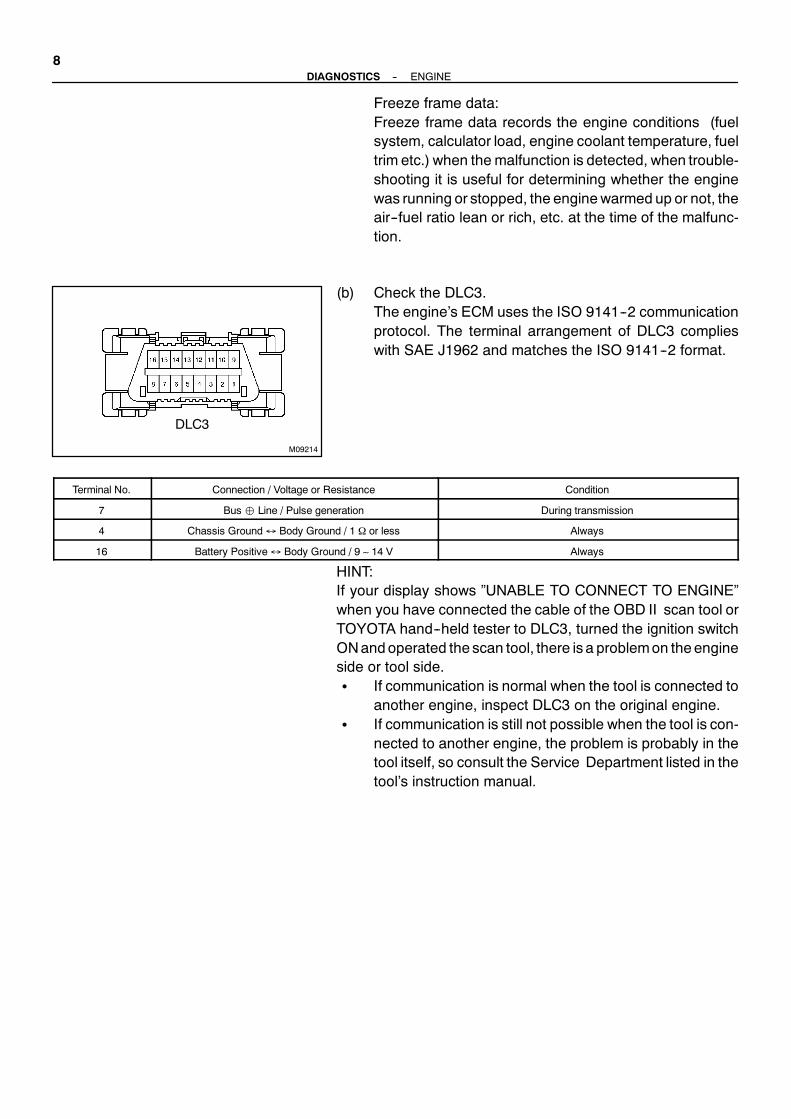
M09214
DLC3
8--DIAGNOSTICS ENGINE
Freeze frame data:Freeze frame data records the engine conditions (fuelsystem, calculator load, engine coolant temperature, fueltrim etc.) when the malfunction is detected, when trouble-shooting it is useful for determining whether the enginewas running or stopped, the enginewarmed up or not, theair--fuel ratio lean or rich, etc. at the time of the malfunc-tion.
(b) Check the DLC3.The engine’s ECM uses the ISO 9141--2 communicationprotocol. The terminal arrangement of DLC3 complieswith SAE J1962 and matches the ISO 9141--2 format.
Terminal No. Connection / Voltage or Resistance Condition
7 Bus Line / Pulse generation During transmission
4 Chassis Ground↔ Body Ground / 1 Ω or less Always
16 Battery Positive↔ Body Ground / 9 ∼ 14 V Always
HINT:If your display shows ”UNABLE TO CONNECT TO ENGINE”when you have connected the cable of the OBD II scan tool orTOYOTA hand--held tester to DLC3, turned the ignition switchONandoperated the scan tool, there is a problemon theengineside or tool side.S If communication is normal when the tool is connected to
another engine, inspect DLC3 on the original engine.S If communication is still not possible when the tool is con-
nected to another engine, the problem is probably in thetool itself, so consult the Service Department listed in thetool’s instruction manual.

M16433
--DIAGNOSTICS ENGINE9
2. INSPECT DIAGNOSIS (Normal Mode)(a) Check the MIL.
(1) TheMIL comesonwhen the ignition switch is turnedON and the engine is not running.
HINT:If theMIL does not light up, troubleshoot the combinationmeter.
(2) When the engine started, the MIL should go off. Ifthe lamp remains on, the diagnosis system has de-tected a malfunction or abnormality in the system.
(b) Check the DTC.NOTICE:TOYOTA hand--held tester only: When the diagnosis sys-tem is switched fromnormalmode to checkmode, it erasesall DTCs and freezed frame data recorded in normal mode.So before switching modes, always check the DTCs andfreezed frame data, and note them down.
(1) Prepare the OBD II scan tool (complying with SAEJ1978) or TOYOTA hand--held tester.
(2) Connect the OBD II scan tool or TOYOTA hand--held tester to DLC3 at the lower left of the instru-ment panel.
(3) Turn the ignition switch ON and push the OBD IIscan tool or TOYOTA hand--held tester switch ON.
(4) Use the OBD II scan tool or TOYOTA hand--heldtester to check the DTCs and freezed frame data,note them down. (For operating instructions, seethe OBD II scan tool’s instruction book.)
(5) See DI--13 to confirm the details of the DTCs.NOTICE:When simulating symptoms with an OBD II scan tool (ex-cluding TOYOTA hand--held tester) to check the DTCs, usenormal mode. For code on the DTC chart subject to ”2 tripdetection logic”, turn the ignition switch OFF after thesymptom is simulated the first time. Then repeat the simu-lation process again. When the problem has been simu-lated twice, the MIL lights up and the DTCs are recorded inthe ECM.(c) Clear the DTC.
TheDTCs and freezed frame data will be erased by eitheraction.(1) Operating theOBD II scan tool (complyingwithSAE
J1978) or TOYOTA hand--held tester to erase thecodes. (See the OBD II scan tool’s instruction bookfor operating instructions.)
(2) Disconnecting the battery terminals or EFI fuse.
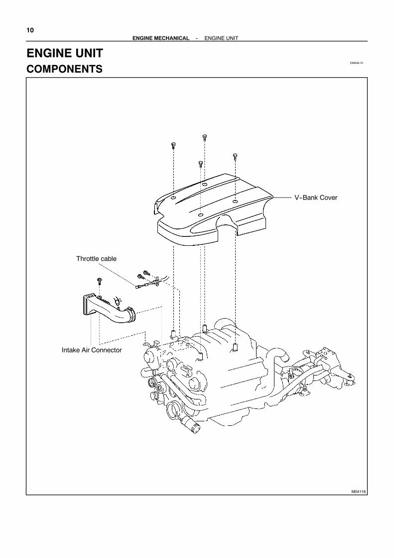
EM0G6--01
M04118
Intake Air Connector
Throttle cable
V--Bank Cover
10--ENGINE MECHANICAL ENGINE UNIT
ENGINE UNITCOMPONENTS

M04120
N·m (kgf·cm, ft·lbf)L Pre coted part
: Specified torque
Engine ControlComputer Bracket
Circuit Breaker Bracket18 (185, 13)
Engine ControlComputer Case
18 (185, 13)×4
8 (80, 71 in,⋅lbf)
No.2 Fuel Pipe
Engine Drive Coupling
Radial Ball Bearing
Flywheel
Engine
44 (450, 32)
TransmissionOil Cooler Hose
30 (300, 22)×6
39 (400, 29)×4
1st 29.5 (300, 21)2nd Turn 90°
L×8
Flywheel Housing
44 (450, 32)×6
8 (80, 71 in.⋅lbf)×4
Transmission
×2
44 (450, 32)
8 (80, 71 in.⋅lbf)×4
44 (450, 3)×6
AdapterTransmissionCase
HangerTransmission
Spacer
V-Drive
--ENGINE MECHANICAL ENGINE UNIT11

EM0G7--01
M00003
M00004
M00005
12--ENGINE MECHANICAL ENGINE UNIT
REMOVAL1. REMOVE V--BANK COVER2. DISCONNECT THROTTLE CABLE3. DISCONNECT SHIFT CABLE4. DISCONNECT ENGINE WIRE CONNECTORSDisconnect the 2 engine wire connectors.5. DISCONNECT GROUND CABLE FROM BODY6. DISCONNECT NO.2 ENGINE WIRE FROM BATTERY7. DISCONNECT HOSES
S Sea water hose from sea water filterS Exhaust hosesS Fuel inlet hoseS Fuel return hose
8. DISCONNECT DRIVESHAFT FROM V-DRIVERemove the 4 bolts and 4 nuts, then disconnect drive shaft andV-drive.
9. DISCONNECT ENGINE MOUNTING FROM BOATBODY
Remove the 12 bolts and 12 nuts, then disconnect enginemounting from boat body.
10. REMOVE ENGINE AND TRANSMISSION ASSEMBLYFROM BOAT
(a) Attach the engine chain hoist to the engine hangers.(b) Lift the engine out of the boat slowly and carefully.HINT:Make sure the engine is clear of all wires, hoses and cables.(c) Place the engine and transmission assembly onto the
stand.
11. REMOVE OIL COOLER HOSES FOR TRANSMISSION(a) Loosen the 4 union nuts, and remove the 2 oil cooler
hoses.(b) Remove the clamp, hose.NOTICE:Disconnect the hose, transmission carefully because it iseasy to break.

M00006
M00008
WireHarness Boot
M00009
M00007
--ENGINE MECHANICAL ENGINE UNIT13
12. REMOVE OIL COOLER FOR TRANSMISSION(a) Loosen the hose clamp on No. 1 sea water hose.(b) Remove the 2 bolts, transmission oil cooler and transmis-
sion oil cooler bracket.
13. REMOVE ENGINE CONTROL COMPUTER CASE(a) Remove the wire harness boot from the engine control
computer case.(b) Disconnect the 5 connectors from theengine control com-
puter.(c) Remove the 4 bolts, then remove the engine control com-
puter case.
14. REMOVE ENGINE CONTROL COMPUTER BRACKET(a) Loosen the hose clamp, then disconnect the No. 4 fuel
hose from the No. 4 fuel pipe.
15. REMOVE V-DRIVE(a) Remove the 6 nuts, then remove the V-DRIVE and gas-
ket, transfer case from transmission.16. REMOVE TRANSMISSION(a) Remove the neutral switch wiring.(b) Remove the 6 nuts, then remove the transmission and
adapter from the flywheel housing.NOTICE:Before you remove the transmission, put supports underthe engine to prevent the engine falling from the stand.

M00010
M00011
WireHamess Boot
M00012
M00042
SST
M04140
14--ENGINE MECHANICAL ENGINE UNIT
(c) Disconnect the engine wire harness from the No. 2 fuelpipe.
(d) Loosen the hose clamp, then disconnect the fuel hosefrom the No. 2 fuel pipe.
(e) Remove the 2 bolts and the No. 2 fuel pipe.
(f) Remove the 2 bolts, then remove the circuit breakerbracket from the engine control computer bracket.
(g) Remove the 4 bolts, then remove the engine control com-puter bracket from the flywheel housing.
17. REMOVE FLYWHEEL HOUSINGRemove the 10 bolts and flywheel housing.
18. REMOVE RADIAL BALL BEARINGRemove the bearing with the special service tool.SST 09303-35011NOTICE:Do not remove the radial ball bearing except when anyproblem has occurred to it.
19. REMOVE FLYWHEEL(a) Remove the 6 bolts, engine drive coupling and radial ball
bearing.(b) Remove the 8 bolts, and flywheel.

EM0G8--01
P08755
Adhesive
M04857
1
3
2
4
5
67
8
M05137
90° 90°
PaintedMark
M00043
SST
--ENGINE MECHANICAL ENGINE UNIT15
INSTALLATION1. INSTALL FLYWHEELHINT:S The mounting bolts are tightened in 2 progressive steps
(steps (c) and (e)).S If any one of themounting bolts is broken or deformed, re-
place it.
(a) Apply adhesive to 2 or 3 threads of themounting bolt end.Adhesive:Part No. 08833--00070, THREE BOND 1324 or equiva-lent
(b) Install the flywheel on the crankshaft.(c) Install and uniformly tighten the 8mounting bolts in sever-
al passes, in the sequence shown.Torque: 29.5 N·m (300 kgf·cm, 21 ft·lbf)
If any one of themounting bolts does not meet the torque speci-fication, replace the mounting bolt.
(d) Mark the mounting bolts with paint.(e) Retighten the mounting bolts by 90° in the numerical or-
der shown.(f) Check that the painted mark is now at a 90° angle to (e).(g) Install the radial ball bearing and engine drive coupling
with the 6 bolts.Torque: 30 N·m (300 kgf·cm, 22 ft·lbf)
2. INSTALL RADIAL BALL BEARING(a) Install the new bearing with the special service tool.
SST 09950-60010 (09951-00310)09950-70010 (09951-07100)

M00012
M00011
M00010
M00009
M00007
16--ENGINE MECHANICAL ENGINE UNIT
3. INSTALL FLYWHEEL HOUSING(a) Install the flywheel housing with the 10 bolts.
Torque:14 mm bolt: 39 N·m (400 kgf·cm, 29 ft·lbf)17 mm bolt: 57 N·m (580 kgf·cm, 42 ft·lbf)
(b) Install the engine control computer bracket to the flywheelhousing with the 4 bolts.Torque: 8 N·m (80 kgf·cm, 71 in.·lbf)
(c) Install the engine control computer bracket No.2 to theengine control computer bracket with the 4 bolts.Torque: 8 N·m (80 kgf·cm, 71 in.·lbf)
(d) Install the No. 2 fuel pipe to the flywheel housing with the2 bolts.Torque: 8 N·m (80 kgf·cm, 71 in.·lbf)
(e) Install the fuel hose to the No. 2 fuel pipe.Torque: 1.5 N·m (15 kgf·cm, 13 in.·lbf)
(f) Secure the engine wire harness with clamps.
(g) Install the No.4 fuel pipe to the No.4 fuel hose.Torque: 1.5 N·m (15 kgf·cm, 13 in.·lbf)
4. INSTALL TRANSMISSION(a) Install the transmission with the 6 nuts.
Torque: 44 N·m (450 kgf·cm, 32 ft·lbf)(b) Connect the neutral switch wiring.5. INSTALL V-DRIVE(a) Install the V-DRIVE with the 6 nuts, and gasket, transfer
case.Torque: 44 N·m (450 kgf·cm, 32 ft·lbf)

M00008-V
WireHarness Boot
M00006
M00005
M00004
M00003
--ENGINE MECHANICAL ENGINE UNIT17
6. INSTALL ENGINE CONTROL COMPUTER CASE(a) Install the engine control computer case to the engine
control computer bracket with the 4 bolts.(b) Install the circuit breaker bracket to the engine control
computer with the 2 bolts.Torque: 18 N·m (185 kgf·cm, 13 ft·lbf)
(c) Connect the 5 connectors to the engine computer.Torque: 8 N·m (80 kgf·cm, 71 in.·lbf)
(d) Install the wire harness boot to the engine control comput-er case.
7. INSTALL OIL COOLER FOR TRANSMISSION(a) Install the transmission oil cooler and transmission oil
cooler bracket with the 2 bolts.Torque: 8 N·m (80 kgf·cm, 71 in.·lbf)
(b) Secure the hose clamp on the No. 1 sea water hose.Torque: 2.5 N·m (25 kgf·cm, 22 in.·lbf)
8. INSTALL OIL COOLER HOSES FOR TRANSMISSION(a) Connect the 2 oil cooler hoses with the 4 union nuts.
Torque: 44 N·m (500 kgf·cm, 32 in.·lbf)NOTICE:Connect the hose, transmission carefully because it iseasy to break.(b) Install the clamp, hose
9. INSTALL ENGINE AND TRANSMISSION ASSEMBLYIN BOAT
(a) Attach the engine chain hoist to the engine hangers.(b) Slowly lower the engine and transmission assembly into
the engine compartment.10. CONNECT DRIVE SHAFT AND TRANSMISSIONConnect the drive shaft and the transmission with the 4 boltsand nuts.
11. INSTALL ENGINE MOUNTINGS TO BOATInstall the engine mountings at 6 locations with the 12 bolts andnuts.
Torque: 47 N·m (480 kgf·cm, 35 ft·lbf)

18--ENGINE MECHANICAL ENGINE UNIT
12. CONNECT HOSESS Fuel inlet hoseS Sea water hose to sea water filterS Exhaust hosesS Fuel return hose13. INSTALL NO.2 ENGINE WIRE TO BATTERY14. INSTALL GROUND CABLE TO BODY15. CONNECT ENGINE WIRE CONNECTORSConnect the 2 engine wire connectors.16. CONNECT SHIFT CABLE17. CONNECT THROTTLE CABLE18. INSTALL V--BANK COVER19. START ENGINE AND CHECK FOR LEAKS20. CHECK TRANSMISSION FLUID LEVEL21. DO ENGINE ADJUSTMENT22. DO ROAD TESTCheck for abnormal noises, shock, slippage, correct shift pointsand smooth operation.23. RECHECK AND OIL LEVELS


![INJURIES ANDFOREIGN BODIES ('@X- - : ] - E I · Radiographs ofthenoseare notusually neededto establish thediagnosis ofa fracture or the needfor treatment butare often performedfor](https://img.pdfslide.us/doc/110x75/5f72a8b8e19f2f51301fab09/injuries-andforeign-bodies-x-e-i-radiographs-ofthenoseare-notusually.jpg)