Embed Size (px)
Citation preview
RUGGEDCOM RX1400
Installation Guide
1/2015
Preface
Introduction 1
Installing the Device 2
Communication Ports 3
Technical Specifications 4
Dimension Drawings 5
Certification 6
RC1103-EN-02
RUGGEDCOM RX1400Installation Guide
ii
Copyright © 2015 Siemens Canada Ltd.
All rights reserved. Dissemination or reproduction of this document, or evaluation and communication of its contents, is not authorizedexcept where expressly permitted. Violations are liable for damages. All rights reserved, particularly for the purposes of patent application ortrademark registration.
This document contains proprietary information, which is protected by copyright. All rights are reserved. No part of this document may bephotocopied, reproduced or translated to another language without the prior written consent of Siemens Canada Ltd..
Disclaimer Of LiabilitySiemens has verified the contents of this manual against the hardware and/or software described. However, deviations between the productand the documentation may exist.
Siemens shall not be liable for any errors or omissions contained herein or for consequential damages in connection with the furnishing,performance, or use of this material.
The information given in this document is reviewed regularly and any necessary corrections will be included in subsequent editions. Weappreciate any suggested improvements. We reserve the right to make technical improvements without notice.
Registered TrademarksROX™, Rugged Operating System On Linux™, CrossBow™ and ELAN™ are trademarks of Siemens Canada Ltd. . ROS® is a registeredtrademark of Siemens Canada Ltd..
Other designations in this manual might be trademarks whose use by third parties for their own purposes would infringe the rights of theowner.
Security InformationSiemens provides products and solutions with industrial security functions that support the secure operation of plants, machines, equipmentand/or networks. They are important components in a holistic industrial security concept. With this in mind, Siemens ' products and solutionsundergo continuous development. Siemens recommends strongly that you regularly check for product updates.
For the secure operation of Siemens products and solutions, it is necessary to take suitable preventive action (e.g. cell protection concept)and integrate each component into a holistic, state-of-the-art industrial security concept. Third-party products that may be in use should alsobe considered. For more information about industrial security, visit http://www.siemens.com/industrialsecurity.
To stay informed about product updates as they occur, sign up for a product-specific newsletter. For more information, visit http://support.automation.siemens.com.
WarrantySiemens warrants this product for a period of five (5) years from the date of purchase, conditional upon the return to factory for maintenanceduring the warranty term. This product contains no user-serviceable parts. Attempted service by unauthorized personnel shall render allwarranties null and void. The warranties set forth in this article are exclusive and are in lieu of all other warranties, performance guaranteesand conditions whether written or oral, statutory, express or implied (including all warranties and conditions of merchantability and fitness fora particular purpose, and all warranties and conditions arising from course of dealing or usage or trade). Correction of nonconformities in themanner and for the period of time provided above shall constitute the Seller’s sole liability and the Customer’s exclusive remedy for defectiveor nonconforming goods or services whether claims of the Customer are based in contract (including fundamental breach), in tort (includingnegligence and strict liability) or otherwise.
For warranty details, visit www.siemens.com/ruggedcom or contact a Siemens customer service representative.
Contacting SiemensAddressSiemens Canada Ltd.Industry Sector300 Applewood CrescentConcord, OntarioCanada, L4K 5C7
TelephoneToll-free: 1 888 264 0006Tel: +1 905 856 5288Fax: +1 905 856 1995
Webwww.siemens.com/ruggedcom
RUGGEDCOM RX1400Installation Guide
Table of Contents
iii
Table of ContentsPreface ................................................................................................................ v
Alerts .................................................................................................................................................. vRelated Documents ............................................................................................................................. vAccessing Documentation .................................................................................................................... vTraining .............................................................................................................................................. viCustomer Support .............................................................................................................................. vi
Chapter 1
Introduction .......................................................................................................... 1
1.1 Feature Highlights ........................................................................................................................ 11.2 Description .................................................................................................................................. 2
Chapter 2
Installing the Device ............................................................................................ 5
2.1 Required Tools and Materials ....................................................................................................... 62.2 Mounting the Device .................................................................................................................... 6
2.2.1 Mounting the Device to a Rack .......................................................................................... 62.2.2 Mounting the Device on a DIN Rail .................................................................................... 72.2.3 Mounting the Device to a Panel ......................................................................................... 8
2.3 Connecting Power ........................................................................................................................ 82.4 Installing the Antennas ................................................................................................................. 92.5 Installing the SIM Cards ............................................................................................................. 112.6 Connecting the Failsafe Alarm Relay ........................................................................................... 122.7 Connecting to the Device ........................................................................................................... 132.8 Cabling Recommendations ......................................................................................................... 13
2.8.1 Protection On Twisted-Pair Data Ports .............................................................................. 142.8.2 Gigabit Ethernet 1000Base-TX Cabling Recommendations ................................................. 14
Chapter 3
Communication Ports ......................................................................................... 15
3.1 Fast Ethernet Ports .................................................................................................................... 163.2 SFP Optic Ethernet Ports ........................................................................................................... 16
3.2.1 Installing an SFP Optical Port .......................................................................................... 173.2.2 Removing an SFP Optical Port ......................................................................................... 18
3.3 Serial Ports ................................................................................................................................ 19
Table of Contents
RUGGEDCOM RX1400Installation Guide
iv
Chapter 4
Technical Specifications ..................................................................................... 21
4.1 Power Supply Specifications ....................................................................................................... 214.2 Failsafe Alarm Relay Specifications ............................................................................................. 214.3 Fast Ethernet Port Specifications ................................................................................................ 224.4 Serial Port Specifications ............................................................................................................ 224.5 SFP Optic Ethernet Port Specifications ........................................................................................ 224.6 Cellular Modem Specifications .................................................................................................... 234.7 Operating Environment ............................................................................................................... 254.8 Mechanical Specifications ........................................................................................................... 26
Chapter 5
Dimension Drawings .......................................................................................... 27
Chapter 6
Certification ........................................................................................................ 31
6.1 Agency Approvals ...................................................................................................................... 316.2 FCC Compliance ........................................................................................................................ 316.3 Industry Canada Compliance ...................................................................................................... 326.4 EMC and Environmental Type Tests ............................................................................................ 32
RUGGEDCOM RX1400Installation Guide
Preface
Alerts v
PrefaceThis guide describes the RUGGEDCOM RX1400. It describes the major features of the device, installation,commissioning and important technical specifications.
It is intended for use by network technical support personnel who are responsible for the installation,commissioning and maintenance of the device. It is also recommended for use by network and system planners,system programmers, and line technicians.
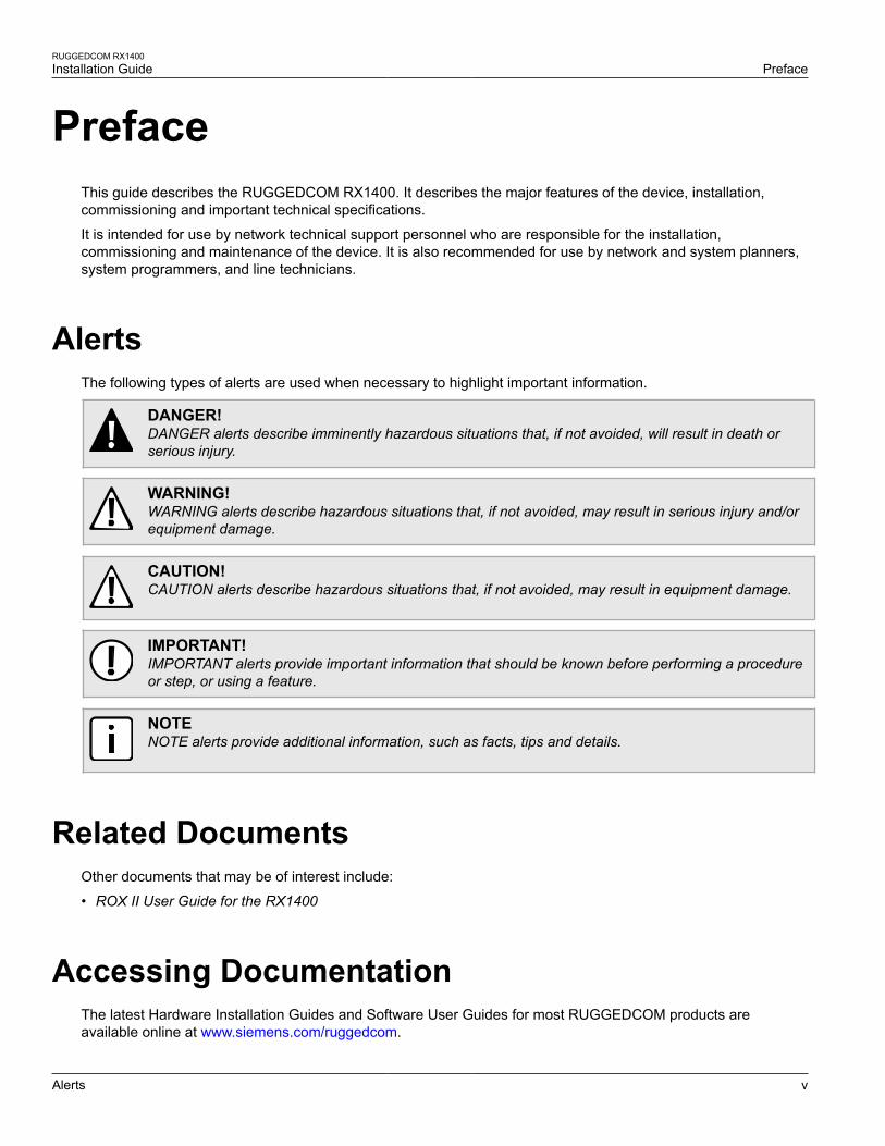
AlertsThe following types of alerts are used when necessary to highlight important information.
DANGER!DANGER alerts describe imminently hazardous situations that, if not avoided, will result in death orserious injury.
WARNING!WARNING alerts describe hazardous situations that, if not avoided, may result in serious injury and/orequipment damage.
CAUTION!CAUTION alerts describe hazardous situations that, if not avoided, may result in equipment damage.
IMPORTANT!IMPORTANT alerts provide important information that should be known before performing a procedureor step, or using a feature.
NOTENOTE alerts provide additional information, such as facts, tips and details.
Related DocumentsOther documents that may be of interest include:
• ROX II User Guide for the RX1400
Accessing DocumentationThe latest Hardware Installation Guides and Software User Guides for most RUGGEDCOM products areavailable online at www.siemens.com/ruggedcom.
Preface
RUGGEDCOM RX1400Installation Guide
vi Training
For any questions about the documentation or for assistance finding a specific document, contact a Siemenssales representative.
TrainingSiemens offers a wide range of educational services ranging from in-house training of standard courses onnetworking, Ethernet switches and routers, to on-site customized courses tailored to the customer's needs,experience and application.
Siemens' Educational Services team thrives on providing our customers with the essential practical skills to makesure users have the right knowledge and expertise to understand the various technologies associated with criticalcommunications network infrastructure technologies.
Siemens' unique mix of IT/Telecommunications expertise combined with domain knowledge in the utility,transportation and industrial markets, allows Siemens to provide training specific to the customer's application.
For more information about training services and course availability, visit www.siemens.com/ruggedcom orcontact a Siemens sales representative.
Customer SupportCustomer support is available 24 hours, 7 days a week for all Siemens customers. For technical support orgeneral information, contact Siemens Customer Support through any of the following methods:
• OnlineVisit http://www.siemens.com/automation/support-request to submit a Support Request (SR) or check on thestatus of an existing SR.
• TelephoneCall a local hotline center to submit a Support Request (SR). To locate a local hotline center, visit http://www.automation.siemens.com/mcms/aspa-db/en/automation-technology/Pages/default.aspx.
• Mobile AppInstall the Industry Online Support app by Siemens AG on any Android, Apple iOS or Windows mobile deviceand be able to:
Access Siemens' extensive library of support documentation, including FAQs, manuals, and much more
Submit SRs or check on the status of an existing SR
Find and contact a local contact person
Ask questions or share knowledge with fellow Siemens customers and the support community
And much more...
RUGGEDCOM RX1400Installation Guide
Chapter 1Introduction
Feature Highlights 1
IntroductionThe RUGGEDCOM RX1400 is a multi-protocol intelligent node that combines Ethernet switch, routing andfirewall functionality with various wide area connectivity options.
The RX1400 switch, with its rugged metal housing, is designed for DIN rail, panel or rack mounting.
The device has IP40 degree protection, does not use internal fans for cooling and supports a -40 to 85 °C (-40 to185 °F) extended temperature range.
The RX1400 provides a high level of immunity to electromagnetic interference, heavy electrical surges, extremetemperature and humidity for reliable operation in harsh environments.
Primary benefits include:
• Cost effective solution for large scale deployments
• Space-saving installation
• Reduced maintenance costs
• Customer data protection
• Support for additional applications
The RX1400 is designed to support primary communications over public mobile networks and leverage enhancedcapabilities of mobile networks, while making reliable and secure connections for mission critical applications inelectric utility substations, traffic control cabinets, railway applications, oil and gas and other harsh environmentapplications.
IMPORTANT!This device must only be used for mobile and fixed applications.
The following sections provide more information about the RX1400:
• Section 1.1, “Feature Highlights”
• Section 1.2, “Description”
Section 1.1
Feature HighlightsWireless Interfaces
• LTE: 700- B13, B17, 800/900/1800/2100/2600 MHz• UMTS/HSPA+: 850/900/1900/2100 MHz• Quad-Band EDGE/GPRS/GSM• GNSS
Ethernet Interfaces
• 4 x 10/100Base-T RJ45 ports
Serial Interfaces with Isolation
• 2 x RS232/422/485 ports
Optical SFP Pluggable Transceivers
• 2 x 1000 Mbit/s ports
Other Interfaces
• Isolated built-in power input• RS232 console port for local management/
diagnostics on the device
Chapter 1Introduction
RUGGEDCOM RX1400Installation Guide
2 Description
Power Supply
• 12 or 24• SMA connectors for RF interfaces
Cyber Security
• Passwords – compliant with NERC guidelines including provision for RADIUS-based authentication• SSH/SSL – extends capability of password protection to add encryption of passwords and data as they cross
the network• Enable/Disable Ports – capability to disable ports so unauthorized devices cannot connect to unused ports• VLAN (IEEE 802.1Q) – provides the ability to logically segregate traffic between predefined ports on switches• SNMPv3 – encrypted authentication and access security• IEEE 802.1x – only permitted devices can connect to the RX1400• MAC Access List – controls access to devices that do not support RADIUS authentication
Section 1.2
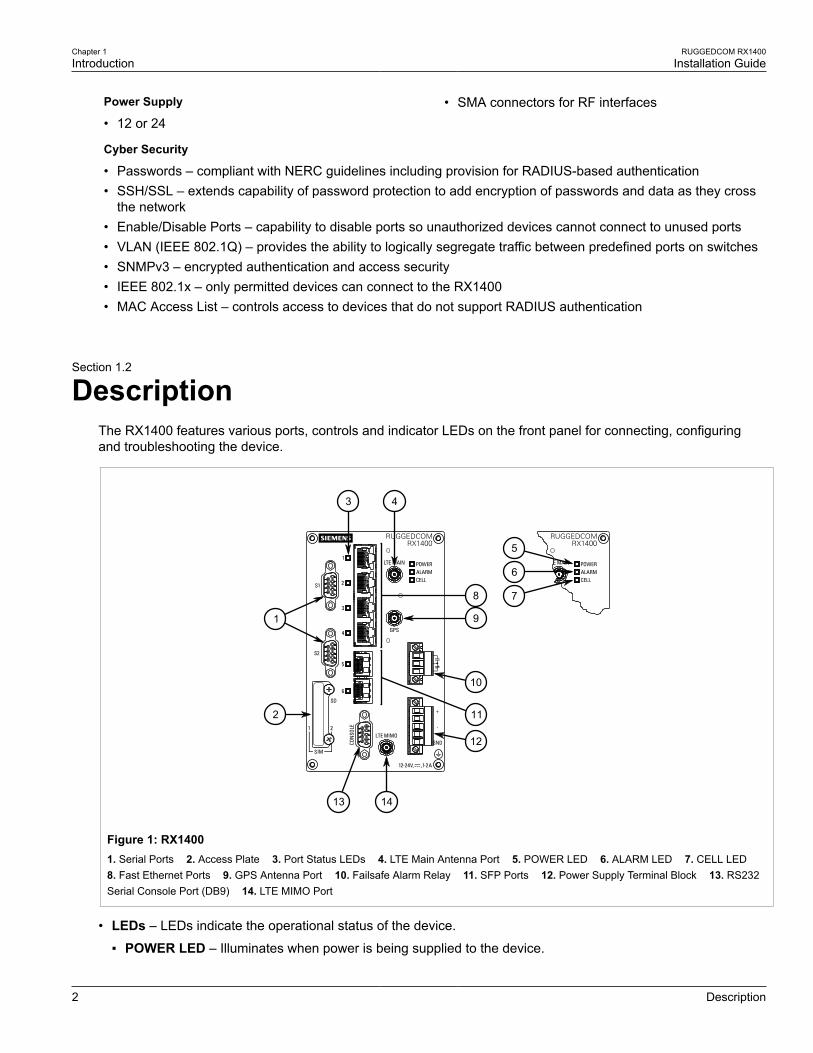
DescriptionThe RX1400 features various ports, controls and indicator LEDs on the front panel for connecting, configuringand troubleshooting the device.
6
12
10
1413
2
1 9
8
4
7
5
11
3
Figure 1: RX14001. Serial Ports 2. Access Plate 3. Port Status LEDs 4. LTE Main Antenna Port 5. POWER LED 6. ALARM LED 7. CELL LED 8. Fast Ethernet Ports 9. GPS Antenna Port 10. Failsafe Alarm Relay 11. SFP Ports 12. Power Supply Terminal Block 13. RS232Serial Console Port (DB9) 14. LTE MIMO Port
• LEDs – LEDs indicate the operational status of the device.
POWER LED – Illuminates when power is being supplied to the device.
RUGGEDCOM RX1400Installation Guide
Chapter 1Introduction
Description 3
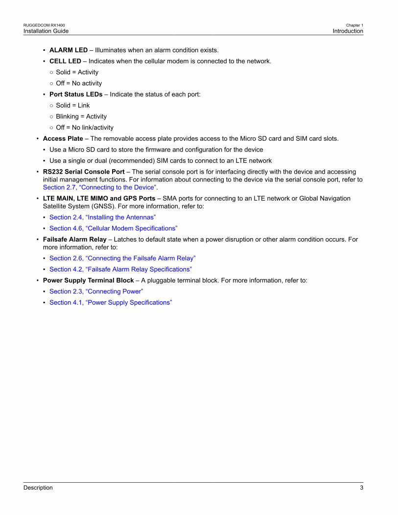
ALARM LED – Illuminates when an alarm condition exists.
CELL LED – Indicates when the cellular modem is connected to the network.
Solid = Activity
Off = No activity
Port Status LEDs – Indicate the status of each port:
Solid = Link
Blinking = Activity
Off = No link/activity
• Access Plate – The removable access plate provides access to the Micro SD card and SIM card slots.
Use a Micro SD card to store the firmware and configuration for the device
Use a single or dual (recommended) SIM cards to connect to an LTE network
• RS232 Serial Console Port – The serial console port is for interfacing directly with the device and accessinginitial management functions. For information about connecting to the device via the serial console port, refer toSection 2.7, “Connecting to the Device”.
• LTE MAIN, LTE MIMO and GPS Ports – SMA ports for connecting to an LTE network or Global NavigationSatellite System (GNSS). For more information, refer to:
Section 2.4, “Installing the Antennas”
Section 4.6, “Cellular Modem Specifications”
• Failsafe Alarm Relay – Latches to default state when a power disruption or other alarm condition occurs. Formore information, refer to:
Section 2.6, “Connecting the Failsafe Alarm Relay”
Section 4.2, “Failsafe Alarm Relay Specifications”
• Power Supply Terminal Block – A pluggable terminal block. For more information, refer to:
Section 2.3, “Connecting Power”
Section 4.1, “Power Supply Specifications”

RUGGEDCOM RX1400Installation Guide
Chapter 1Introduction
Description 4
RUGGEDCOM RX1400Installation Guide
Chapter 2Installing the Device
5
Installing the DeviceThis chapter describes how to install the device, including mounting the device, connecting power, andconnecting the device to the network.
WARNING!Radiation hazard – risk of serious personal injury. This product contains a laser system and isclassified as a CLASS 1 LASER PRODUCT. Use of controls or adjustments or performance ofprocedures other than those specified herein may result in hazardous radiation exposure.
DANGER!Electrocution hazard – risk of serious personal injury and/or damage to equipment. Before performingany maintenance tasks, make sure all power to the device has been disconnected and waitapproximately two minutes for any remaining energy to dissipate.
IMPORTANT!This product contains no user-serviceable parts. Attempted service by unauthorized personnel shallrender all warranties null and void.
Changes or modifications not expressly approved by Siemens Canada Ltd. could invalidatespecifications, test results, and agency approvals, and void the user's authority to operate theequipment.
IMPORTANT!This product should be installed in a restricted access location where access can only be gained byauthorized personnel who have been informed of the restrictions and any precautions that must betaken. Access must only be possible through the use of a tool, lock and key, or other means of security,and controlled by the authority responsible for the location.
The general procedure for installing the device is as follows:
1. Mount the device to a rack, panel or DIN rail.
2. Connect power to the device and ground the device to safety Earth.
3. Connect the LTE and/or GPS antennas.
4. Connect the failsafe alarm relay.
5. Connect the device to the network.
These steps, and other related information, are described in the following sections:
• Section 2.1, “Required Tools and Materials”
• Section 2.2, “Mounting the Device”
• Section 2.3, “Connecting Power”
• Section 2.4, “Installing the Antennas”
• Section 2.5, “Installing the SIM Cards”
• Section 2.6, “Connecting the Failsafe Alarm Relay”
• Section 2.7, “Connecting to the Device”
Chapter 2Installing the Device
RUGGEDCOM RX1400Installation Guide
6 Required Tools and Materials
• Section 2.8, “Cabling Recommendations”
Section 2.1
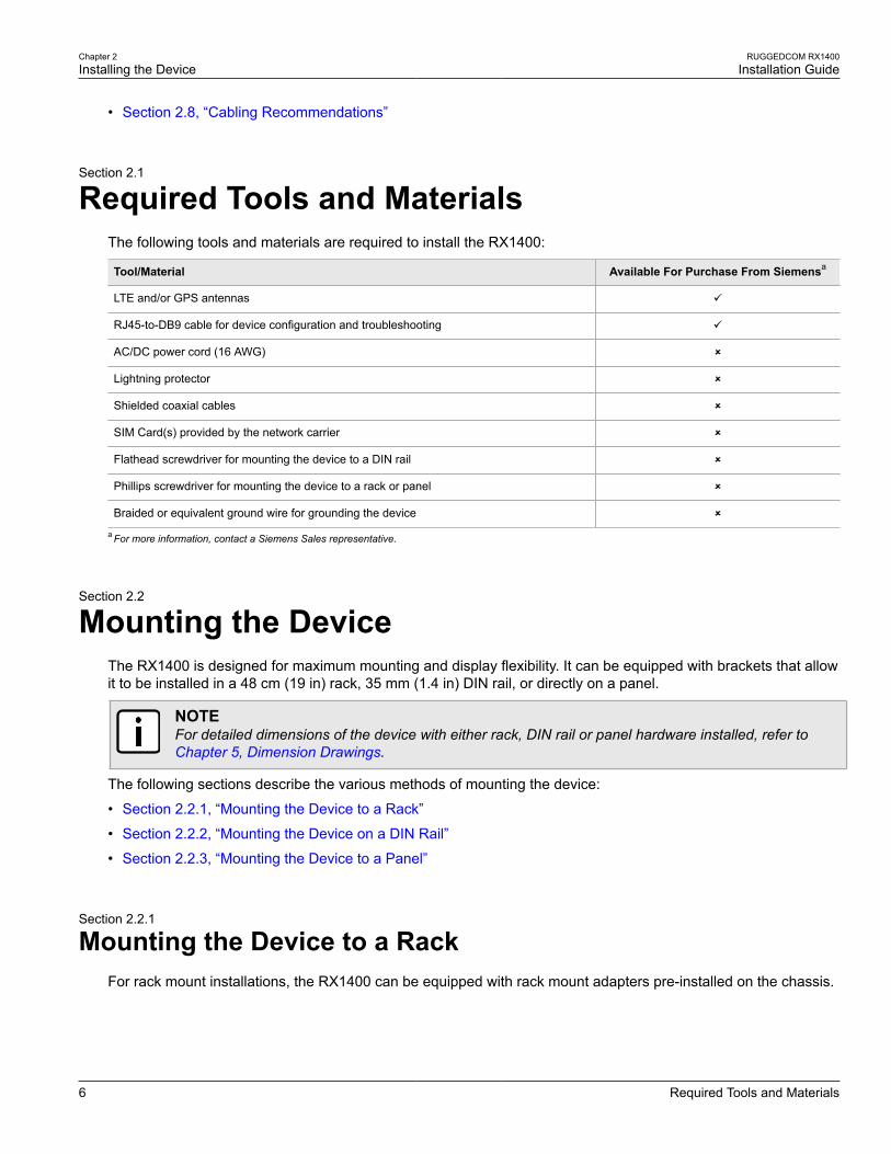
Required Tools and MaterialsThe following tools and materials are required to install the RX1400:
Tool/Material Available For Purchase From Siemensa
LTE and/or GPS antennas ü
RJ45-to-DB9 cable for device configuration and troubleshooting ü
AC/DC power cord (16 AWG) û
Lightning protector û
Shielded coaxial cables û
SIM Card(s) provided by the network carrier û
Flathead screwdriver for mounting the device to a DIN rail û
Phillips screwdriver for mounting the device to a rack or panel û
Braided or equivalent ground wire for grounding the device û
a For more information, contact a Siemens Sales representative.
Section 2.2
Mounting the DeviceThe RX1400 is designed for maximum mounting and display flexibility. It can be equipped with brackets that allowit to be installed in a 48 cm (19 in) rack, 35 mm (1.4 in) DIN rail, or directly on a panel.
NOTEFor detailed dimensions of the device with either rack, DIN rail or panel hardware installed, refer toChapter 5, Dimension Drawings.
The following sections describe the various methods of mounting the device:
• Section 2.2.1, “Mounting the Device to a Rack”
• Section 2.2.2, “Mounting the Device on a DIN Rail”
• Section 2.2.3, “Mounting the Device to a Panel”
Section 2.2.1
Mounting the Device to a RackFor rack mount installations, the RX1400 can be equipped with rack mount adapters pre-installed on the chassis.
RUGGEDCOM RX1400Installation Guide
Chapter 2Installing the Device
Mounting the Device on a DIN Rail 7
CAUTION!Electrical/mechanical hazard – risk of damage to the device. Before installing the device in a rack,make sure of the following:
• When installing the device in a closed or multi-device rack, be aware the operating ambienttemperature of the rack may be higher than the ambient temperature of the room. Make sure therack is installed in a suitable environment that can withstand the maximum ambient temperaturegenerated by the rack.
• Make sure each device in the rack is separated by at least one rack-unit of space, or 44 mm (1.75in), to promote convectional airflow. Forced airflow is not required. However, any increase in airflowwill result in a reduction of ambient temperature and improve the long-term reliability of all equipmentmounted in the rack space.
• Do not exceed the maximum number of devices or weight restrictions specified by the rackmanufacturer.
• Do not overload the supply circuit. Refer to the over-current protection and power supply ratingsspecified by the rack manufacturer.
• Make sure the rack and all devices have a proper ground-to-Earth connection. Pay particularattention to power supply connections other than direct connections to the branch circuit (e.g. powerstrips).
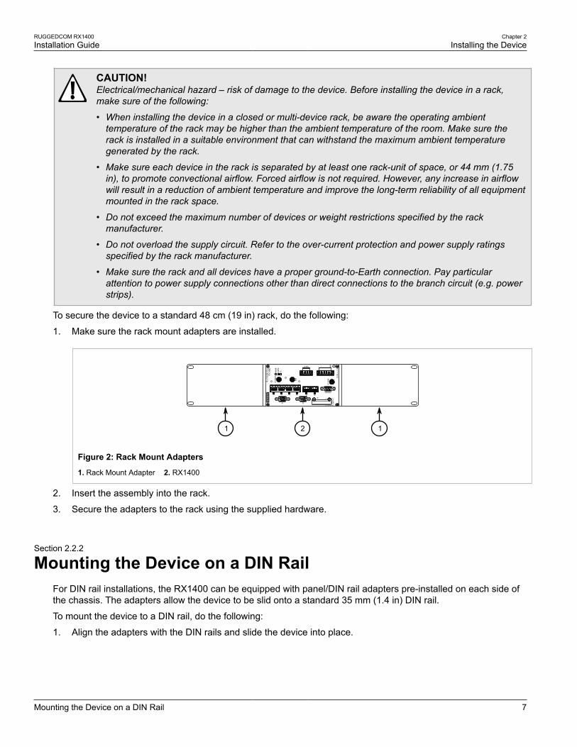
To secure the device to a standard 48 cm (19 in) rack, do the following:
1. Make sure the rack mount adapters are installed.
1 12
Figure 2: Rack Mount Adapters
1. Rack Mount Adapter 2. RX1400
2. Insert the assembly into the rack.
3. Secure the adapters to the rack using the supplied hardware.
Section 2.2.2
Mounting the Device on a DIN RailFor DIN rail installations, the RX1400 can be equipped with panel/DIN rail adapters pre-installed on each side ofthe chassis. The adapters allow the device to be slid onto a standard 35 mm (1.4 in) DIN rail.
To mount the device to a DIN rail, do the following:
1. Align the adapters with the DIN rails and slide the device into place.
Chapter 2Installing the Device
RUGGEDCOM RX1400Installation Guide
8 Mounting the Device to a Panel
1
1
2
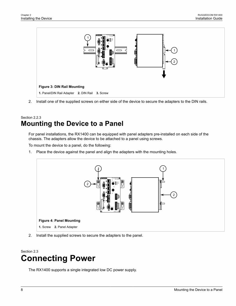
Figure 3: DIN Rail Mounting
1. Panel/DIN Rail Adapter 2. DIN Rail 3. Screw
2. Install one of the supplied screws on either side of the device to secure the adapters to the DIN rails.
Section 2.2.3
Mounting the Device to a PanelFor panel installations, the RX1400 can be equipped with panel adapters pre-installed on each side of thechassis. The adapters allow the device to be attached to a panel using screws.
To mount the device to a panel, do the following:
1. Place the device against the panel and align the adapters with the mounting holes.
1 1
2
2
Figure 4: Panel Mounting
1. Screw 2. Panel Adapter
2. Install the supplied screws to secure the adapters to the panel.
Section 2.3
Connecting PowerThe RX1400 supports a single integrated low DC power supply.
RUGGEDCOM RX1400Installation Guide
Chapter 2Installing the Device
Installing the Antennas 9
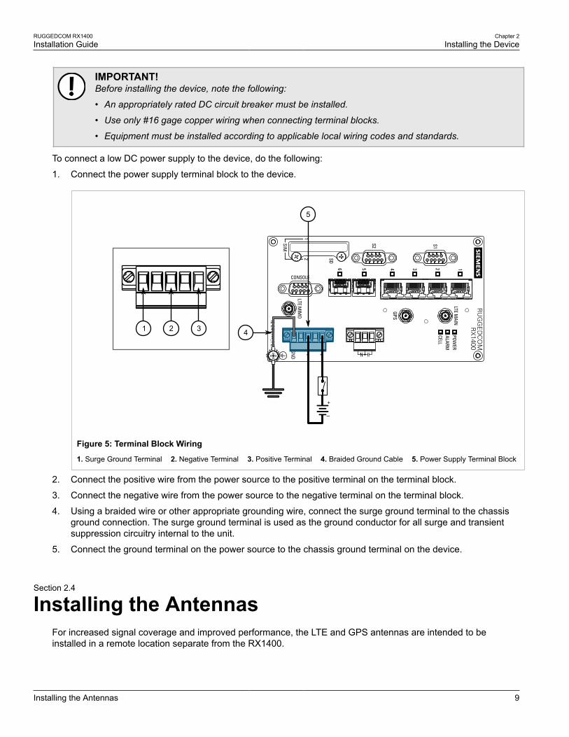
IMPORTANT!Before installing the device, note the following:
• An appropriately rated DC circuit breaker must be installed.
• Use only #16 gage copper wiring when connecting terminal blocks.
• Equipment must be installed according to applicable local wiring codes and standards.
To connect a low DC power supply to the device, do the following:
1. Connect the power supply terminal block to the device.
1 2 3 4
5
Figure 5: Terminal Block Wiring
1. Surge Ground Terminal 2. Negative Terminal 3. Positive Terminal 4. Braided Ground Cable 5. Power Supply Terminal Block
2. Connect the positive wire from the power source to the positive terminal on the terminal block.
3. Connect the negative wire from the power source to the negative terminal on the terminal block.
4. Using a braided wire or other appropriate grounding wire, connect the surge ground terminal to the chassisground connection. The surge ground terminal is used as the ground conductor for all surge and transientsuppression circuitry internal to the unit.
5. Connect the ground terminal on the power source to the chassis ground terminal on the device.
Section 2.4
Installing the AntennasFor increased signal coverage and improved performance, the LTE and GPS antennas are intended to beinstalled in a remote location separate from the RX1400.
Chapter 2Installing the Device
RUGGEDCOM RX1400Installation Guide
10 Installing the Antennas
NOTEA specific brand of antenna is not specified.
To install the LTE and/or GPS antennas, do the following:
WARNING!Radiation hazard – risk of Radio Frequency (RF) exposure. This device is compliant with therequirements set forth in FCC 47 CFR, section 1.1307, addressing Radio Frequency (RF) exposurefrom radio frequency base stations, as defined in FCC OET Bulletin 65 [http://transition.fcc.gov/Bureaus/Engineering_Technology/Documents/bulletins/oet65/oet65.pdf]. The emitted radiation shouldbe as little as possible. To achieve minimum RF exposure, install the device when it is configured notto transmit and set it to operational mode remotely, rather than having a technician enable transmissionon-site. For maintenance of the base station, or other operations which require RF exposure, theexposure should be minimized in time and according to the regulations set forth by the country ofinstallation or the Federal Communications Commission (FCC).
WARNING!The device must be placed at a distance of at least 20 cm (8 in) from all persons during normaloperation. The antennas used for this product must not be located or operating in conjunction with anyother antenna or transmitter, except in accordance with FCC multi-transmitter evaluation procedures.
CAUTION!Configuration hazard – risk of reduced performance. Each antenna and connecting cable must have anominal impedance of 50 Ω with a return loss of better than 10 dB across each frequency band. If thenominal impedance is different, Radio Frequency (RF) performance will be reduced.
IMPORTANT!The antenna installation must be as per Article 810 of the NEC. Specifically, the grounding conductormust not be less than 10 AWG (Cu). The scheme should be either:
• In accordance with UL 96 and 96A Lightning Protection Components and Installation Requirementsfor Lightning Protection Systems (LPS)
• Tested in accordance with UL 50 and UL 497
IMPORTANT!A Radio Frequency (RF) site survey is recommended prior to any installation to help determine thebest location for the LTE and GPS antennas. For assistance, contact a Siemens Sales representative.
IMPORTANT!The cellular modem supports SISO (Single Input Single Output) and MIMO (Multiple Input MultipleOutput) modes. At minimum, a single antenna connected to the LTE MAIN port is required for SISOmode and to support lower generation wireless standards, such as GSM or EDGE. A separate diversity(secondary) antenna is required for MIMO performance.
IMPORTANT!For mobile and fixed operating configurations, in accordance with FCC 47 CFR, section 2.1091, theantenna gain, including cable loss must not exceed:
• 6.5 dBi at 800/850 MHz
• 3.0 dBi at 1900 MHz
RUGGEDCOM RX1400Installation Guide
Chapter 2Installing the Device
Installing the SIM Cards 11
• 9.0 dBi at 700 MHz
• 6.0 dBi at 1700 MHz
Under no conditions may an antenna gain be used that would exceed the ERP and/or EIRP powerlimits specified in FCC 47 CFR Parts 22, 24, 27 and 90.
NOTEFor technical specifications, refer to Section 4.6, “Cellular Modem Specifications”.
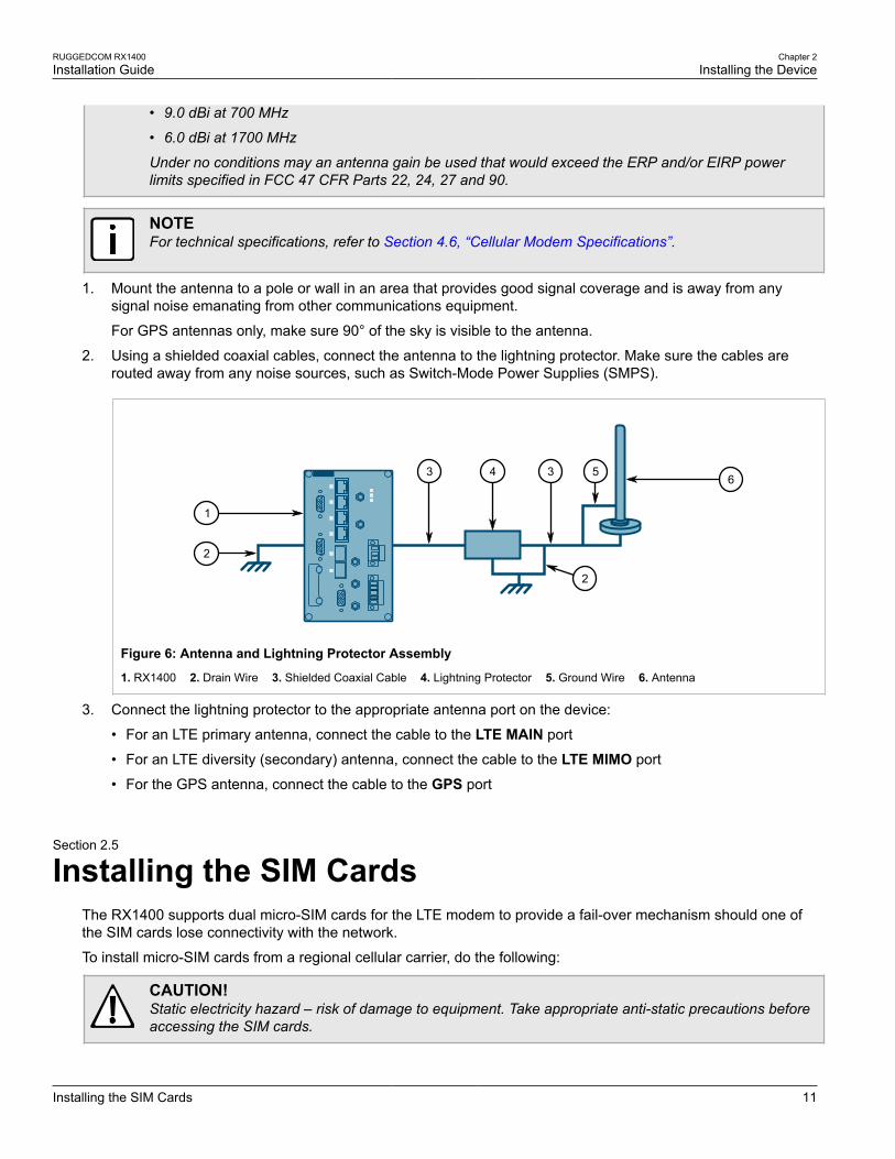
1. Mount the antenna to a pole or wall in an area that provides good signal coverage and is away from anysignal noise emanating from other communications equipment.
For GPS antennas only, make sure 90° of the sky is visible to the antenna.
2. Using a shielded coaxial cables, connect the antenna to the lightning protector. Make sure the cables arerouted away from any noise sources, such as Switch-Mode Power Supplies (SMPS).
4
1
2
6
2
33 5
Figure 6: Antenna and Lightning Protector Assembly
1. RX1400 2. Drain Wire 3. Shielded Coaxial Cable 4. Lightning Protector 5. Ground Wire 6. Antenna
3. Connect the lightning protector to the appropriate antenna port on the device:
• For an LTE primary antenna, connect the cable to the LTE MAIN port
• For an LTE diversity (secondary) antenna, connect the cable to the LTE MIMO port
• For the GPS antenna, connect the cable to the GPS port
Section 2.5
Installing the SIM CardsThe RX1400 supports dual micro-SIM cards for the LTE modem to provide a fail-over mechanism should one ofthe SIM cards lose connectivity with the network.
To install micro-SIM cards from a regional cellular carrier, do the following:
CAUTION!Static electricity hazard – risk of damage to equipment. Take appropriate anti-static precautions beforeaccessing the SIM cards.
Chapter 2Installing the Device
RUGGEDCOM RX1400Installation Guide
12 Connecting the Failsafe Alarm Relay
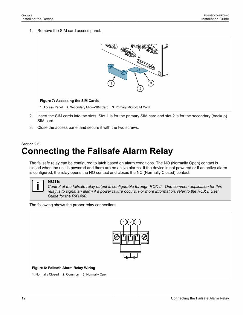
1. Remove the SIM card access panel.
1 3
2
Figure 7: Accessing the SIM Cards
1. Access Panel 2. Secondary Micro-SIM Card 3. Primary Micro-SIM Card
2. Insert the SIM cards into the slots. Slot 1 is for the primary SIM card and slot 2 is for the secondary (backup)SIM card.
3. Close the access panel and secure it with the two screws.
Section 2.6
Connecting the Failsafe Alarm RelayThe failsafe relay can be configured to latch based on alarm conditions. The NO (Normally Open) contact isclosed when the unit is powered and there are no active alarms. If the device is not powered or if an active alarmis configured, the relay opens the NO contact and closes the NC (Normally Closed) contact.
NOTEControl of the failsafe relay output is configurable through ROX II . One common application for thisrelay is to signal an alarm if a power failure occurs. For more information, refer to the ROX II UserGuide for the RX1400.
The following shows the proper relay connections.
2 31
Figure 8: Failsafe Alarm Relay Wiring
1. Normally Closed 2. Common 3. Normally Open
RUGGEDCOM RX1400Installation Guide
Chapter 2Installing the Device
Connecting to the Device 13
Section 2.7
Connecting to the DeviceThe following describes the various methods for accessing the ROX II console and Web interfaces on the device.For more detailed instructions, refer to the ROX II User Guide for the RX1400.
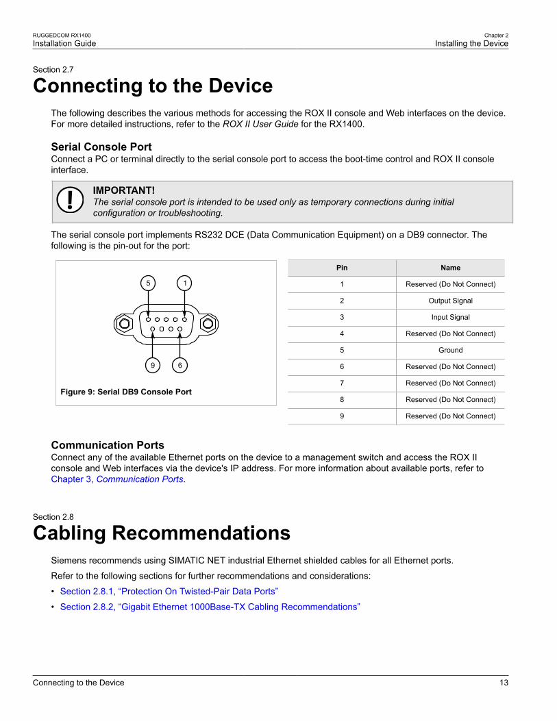
Serial Console PortConnect a PC or terminal directly to the serial console port to access the boot-time control and ROX II consoleinterface.
IMPORTANT!The serial console port is intended to be used only as temporary connections during initialconfiguration or troubleshooting.
The serial console port implements RS232 DCE (Data Communication Equipment) on a DB9 connector. Thefollowing is the pin-out for the port:
5
9 6
1
Figure 9: Serial DB9 Console Port
Pin Name
1 Reserved (Do Not Connect)
2 Output Signal
3 Input Signal
4 Reserved (Do Not Connect)
5 Ground
6 Reserved (Do Not Connect)
7 Reserved (Do Not Connect)
8 Reserved (Do Not Connect)
9 Reserved (Do Not Connect)
Communication PortsConnect any of the available Ethernet ports on the device to a management switch and access the ROX IIconsole and Web interfaces via the device's IP address. For more information about available ports, refer toChapter 3, Communication Ports.
Section 2.8
Cabling RecommendationsSiemens recommends using SIMATIC NET industrial Ethernet shielded cables for all Ethernet ports.
Refer to the following sections for further recommendations and considerations:
• Section 2.8.1, “Protection On Twisted-Pair Data Ports”
• Section 2.8.2, “Gigabit Ethernet 1000Base-TX Cabling Recommendations”
Chapter 2Installing the Device
RUGGEDCOM RX1400Installation Guide
14 Protection On Twisted-Pair Data Ports
Section 2.8.1
Protection On Twisted-Pair Data PortsSiemens does not recommend the use of copper cabling of any length for critical, real-time substation automationapplications. All copper Ethernet ports on RUGGEDCOM products include transient suppression circuitryto protect against damage from electrical transients and conform with IEC 61850-3 and IEEE 1613 Class 1standards. This means that during a transient electrical event, communications errors or interruptions may occur,but recovery is automatic.
Siemens also does not recommend using copper Ethernet ports to interface with devices in the field acrossdistances that could produce high levels of ground potential rise (i.e. greater than 2500 V), during line-to-groundfault conditions.
Section 2.8.2
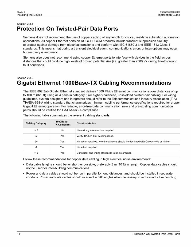
Gigabit Ethernet 1000Base-TX Cabling RecommendationsThe IEEE 802.3ab Gigabit Ethernet standard defines 1000 Mbit/s Ethernet communications over distances of upto 100 m (328 ft) using all 4 pairs in category 5 (or higher) balanced, unshielded twisted-pair cabling. For wiringguidelines, system designers and integrators should refer to the Telecommunications Industry Association (TIA)TIA/EIA-568-A wiring standard that characterizes minimum cabling performance specifications required for properGigabit Ethernet operation. For reliable, error-free data communication, new and pre-existing communicationpaths should be verified for TIA/EIA-568-A compliance.
The following table summarizes the relevant cabling standards:
Cabling Category 1000Base-TX Compliant Required Action
< 5 No New wiring infrastructure required.
5 Yes Verify TIA/EIA-568-A compliance.
5e Yes No action required. New installations should be designed with Category 5e or higher.
6 Yes No action required.
> 6 Yes Connector and wiring standards to be determined.
Follow these recommendations for copper data cabling in high electrical noise environments:
• Data cable lengths should be as short as possible, preferably 3 m (10 ft) in length. Copper data cables shouldnot be used for inter-building communications.
• Power and data cables should not be run in parallel for long distances, and should be installed in separateconduits. Power and data cables should intersect at 90° angles when necessary to reduce inductive coupling.
RUGGEDCOM RX1400Installation Guide
Chapter 3Communication Ports
15
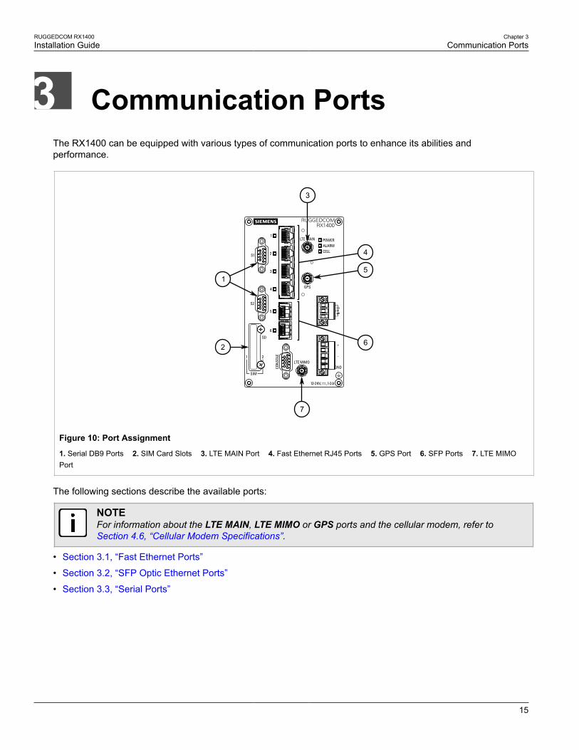
Communication PortsThe RX1400 can be equipped with various types of communication ports to enhance its abilities andperformance.
7
15
4
3
2 6
Figure 10: Port Assignment
1. Serial DB9 Ports 2. SIM Card Slots 3. LTE MAIN Port 4. Fast Ethernet RJ45 Ports 5. GPS Port 6. SFP Ports 7. LTE MIMOPort
The following sections describe the available ports:
NOTEFor information about the LTE MAIN, LTE MIMO or GPS ports and the cellular modem, refer toSection 4.6, “Cellular Modem Specifications”.
• Section 3.1, “Fast Ethernet Ports”
• Section 3.2, “SFP Optic Ethernet Ports”
• Section 3.3, “Serial Ports”
Chapter 3Communication Ports
RUGGEDCOM RX1400Installation Guide
16 Fast Ethernet Ports
Section 3.1
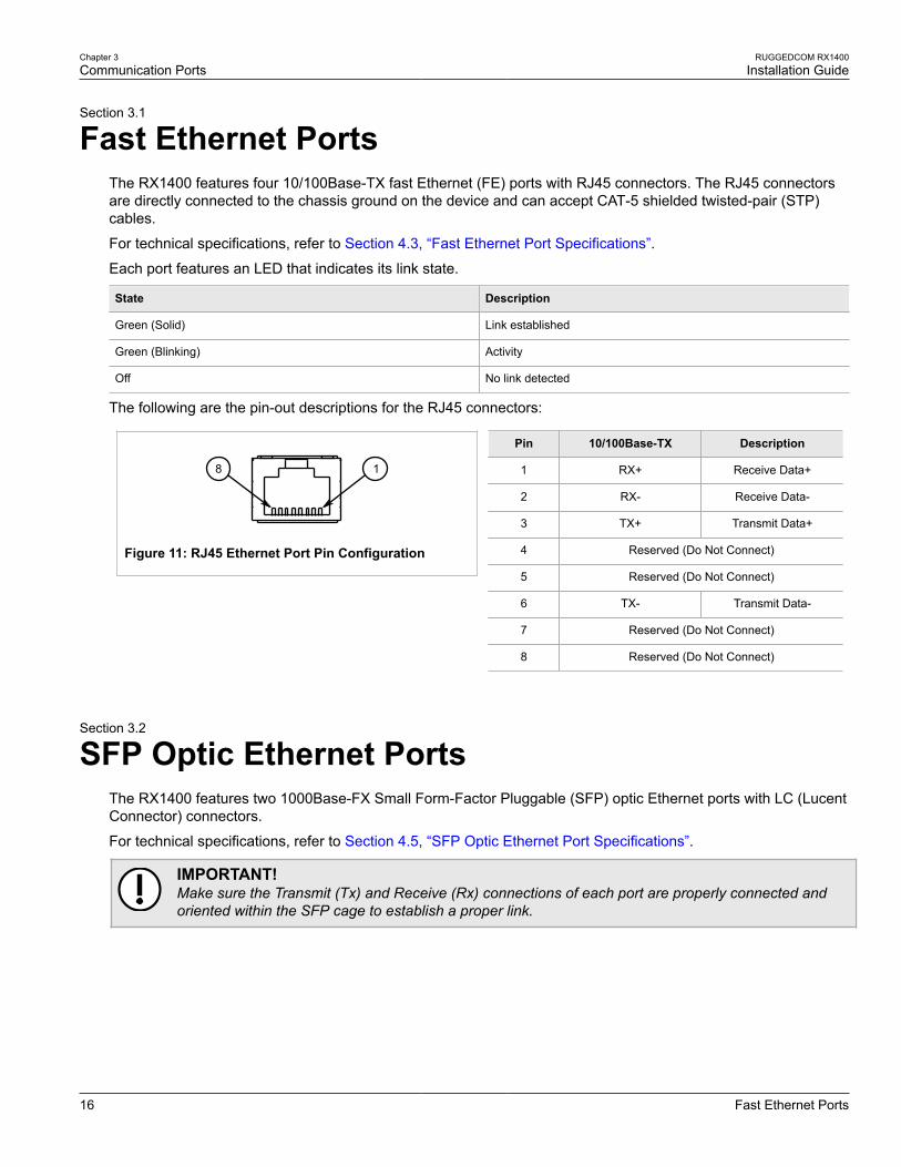
Fast Ethernet PortsThe RX1400 features four 10/100Base-TX fast Ethernet (FE) ports with RJ45 connectors. The RJ45 connectorsare directly connected to the chassis ground on the device and can accept CAT-5 shielded twisted-pair (STP)cables.
For technical specifications, refer to Section 4.3, “Fast Ethernet Port Specifications”.
Each port features an LED that indicates its link state.
State Description
Green (Solid) Link established
Green (Blinking) Activity
Off No link detected
The following are the pin-out descriptions for the RJ45 connectors:
18
Figure 11: RJ45 Ethernet Port Pin Configuration
Pin 10/100Base-TX Description
1 RX+ Receive Data+
2 RX- Receive Data-
3 TX+ Transmit Data+
4 Reserved (Do Not Connect)
5 Reserved (Do Not Connect)
6 TX- Transmit Data-
7 Reserved (Do Not Connect)
8 Reserved (Do Not Connect)
Section 3.2
SFP Optic Ethernet PortsThe RX1400 features two 1000Base-FX Small Form-Factor Pluggable (SFP) optic Ethernet ports with LC (LucentConnector) connectors.
For technical specifications, refer to Section 4.5, “SFP Optic Ethernet Port Specifications”.
IMPORTANT!Make sure the Transmit (Tx) and Receive (Rx) connections of each port are properly connected andoriented within the SFP cage to establish a proper link.
RUGGEDCOM RX1400Installation Guide
Chapter 3Communication Ports
Installing an SFP Optical Port 17
21
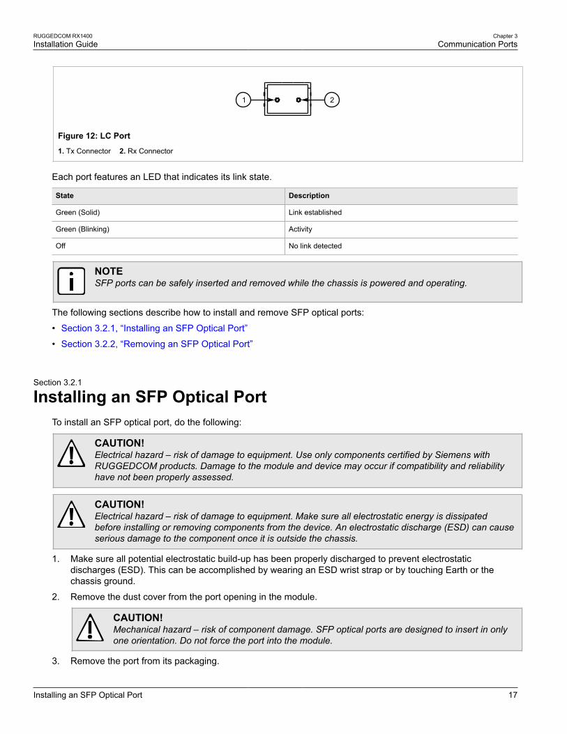
Figure 12: LC Port
1. Tx Connector 2. Rx Connector
Each port features an LED that indicates its link state.
State Description
Green (Solid) Link established
Green (Blinking) Activity
Off No link detected
NOTESFP ports can be safely inserted and removed while the chassis is powered and operating.
The following sections describe how to install and remove SFP optical ports:
• Section 3.2.1, “Installing an SFP Optical Port”
• Section 3.2.2, “Removing an SFP Optical Port”
Section 3.2.1
Installing an SFP Optical PortTo install an SFP optical port, do the following:
CAUTION!Electrical hazard – risk of damage to equipment. Use only components certified by Siemens withRUGGEDCOM products. Damage to the module and device may occur if compatibility and reliabilityhave not been properly assessed.
CAUTION!Electrical hazard – risk of damage to equipment. Make sure all electrostatic energy is dissipatedbefore installing or removing components from the device. An electrostatic discharge (ESD) can causeserious damage to the component once it is outside the chassis.
1. Make sure all potential electrostatic build-up has been properly discharged to prevent electrostaticdischarges (ESD). This can be accomplished by wearing an ESD wrist strap or by touching Earth or thechassis ground.
2. Remove the dust cover from the port opening in the module.
CAUTION!Mechanical hazard – risk of component damage. SFP optical ports are designed to insert in onlyone orientation. Do not force the port into the module.
3. Remove the port from its packaging.
Chapter 3Communication Ports
RUGGEDCOM RX1400Installation Guide
18 Removing an SFP Optical Port
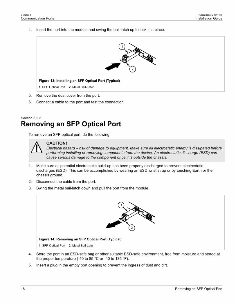
4. Insert the port into the module and swing the bail-latch up to lock it in place.
2
1
Figure 13: Installing an SFP Optical Port (Typical)
1. SFP Optical Port 2. Metal Bail-Latch
5. Remove the dust cover from the port.
6. Connect a cable to the port and test the connection.
Section 3.2.2
Removing an SFP Optical PortTo remove an SFP optical port, do the following:
CAUTION!Electrical hazard – risk of damage to equipment. Make sure all electrostatic energy is dissipated beforeperforming installing or removing components from the device. An electrostatic discharge (ESD) cancause serious damage to the component once it is outside the chassis.
1. Make sure all potential electrostatic build-up has been properly discharged to prevent electrostaticdischarges (ESD). This can be accomplished by wearing an ESD wrist strap or by touching Earth or thechassis ground.
2. Disconnect the cable from the port.
3. Swing the metal bail-latch down and pull the port from the module.
2
1
Figure 14: Removing an SFP Optical Port (Typical)
1. SFP Optical Port 2. Metal Bail-Latch
4. Store the port in an ESD-safe bag or other suitable ESD-safe environment, free from moisture and stored atthe proper temperature (-40 to 85 °C or -40 to 185 °F).
5. Insert a plug in the empty port opening to prevent the ingress of dust and dirt.
RUGGEDCOM RX1400Installation Guide
Chapter 3Communication Ports
Serial Ports 19
Section 3.3
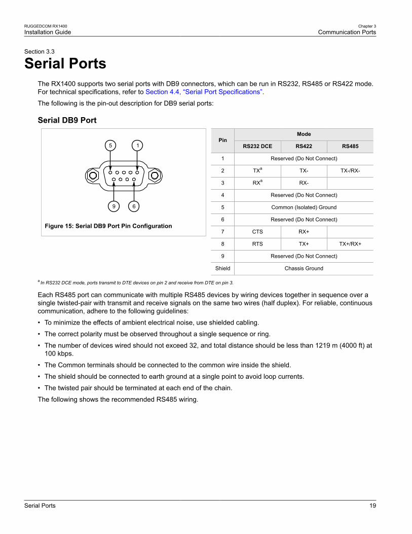
Serial PortsThe RX1400 supports two serial ports with DB9 connectors, which can be run in RS232, RS485 or RS422 mode.For technical specifications, refer to Section 4.4, “Serial Port Specifications”.
The following is the pin-out description for DB9 serial ports:
Serial DB9 Port
5
9 6
1
Figure 15: Serial DB9 Port Pin Configuration
ModePin
RS232 DCE RS422 RS485
1 Reserved (Do Not Connect)
2 TXa TX- TX-/RX-
3 RXa RX-
4 Reserved (Do Not Connect)
5 Common (Isolated) Ground
6 Reserved (Do Not Connect)
7 CTS RX+
8 RTS TX+ TX+/RX+
9 Reserved (Do Not Connect)
Shield Chassis Ground
a In RS232 DCE mode, ports transmit to DTE devices on pin 2 and receive from DTE on pin 3.
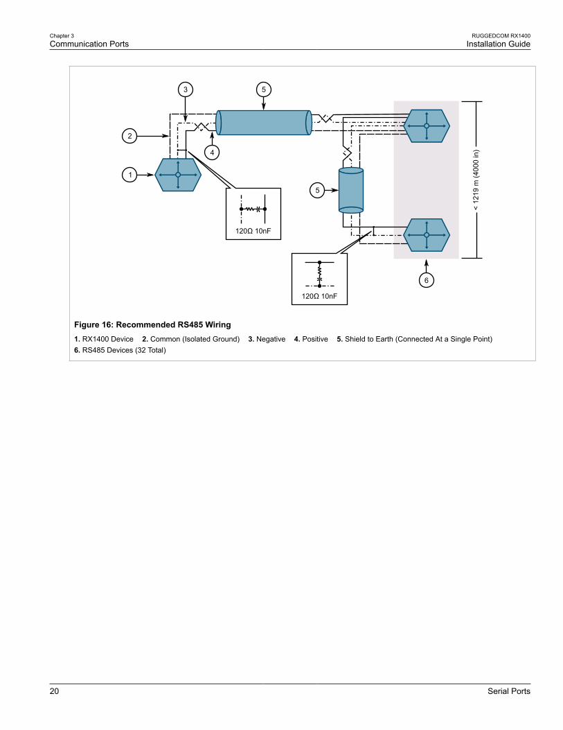
Each RS485 port can communicate with multiple RS485 devices by wiring devices together in sequence over asingle twisted-pair with transmit and receive signals on the same two wires (half duplex). For reliable, continuouscommunication, adhere to the following guidelines:
• To minimize the effects of ambient electrical noise, use shielded cabling.
• The correct polarity must be observed throughout a single sequence or ring.
• The number of devices wired should not exceed 32, and total distance should be less than 1219 m (4000 ft) at100 kbps.
• The Common terminals should be connected to the common wire inside the shield.
• The shield should be connected to earth ground at a single point to avoid loop currents.
• The twisted pair should be terminated at each end of the chain.
The following shows the recommended RS485 wiring.
Chapter 3Communication Ports
RUGGEDCOM RX1400Installation Guide
20 Serial Ports
< 12
19 m
(40
00 in
)
120Ω 10nF
120Ω 10nF
1
2
3 5
5
6
4
Figure 16: Recommended RS485 Wiring1. RX1400 Device 2. Common (Isolated Ground) 3. Negative 4. Positive 5. Shield to Earth (Connected At a Single Point) 6. RS485 Devices (32 Total)
RUGGEDCOM RX1400Installation Guide
Chapter 4Technical Specifications
Power Supply Specifications 21
Technical SpecificationsThe following sections provide important technical specifications related to the device:
• Section 4.1, “Power Supply Specifications”
• Section 4.2, “Failsafe Alarm Relay Specifications”
• Section 4.3, “Fast Ethernet Port Specifications”
• Section 4.4, “Serial Port Specifications”
• Section 4.5, “SFP Optic Ethernet Port Specifications”
• Section 4.6, “Cellular Modem Specifications”
• Section 4.7, “Operating Environment”
• Section 4.8, “Mechanical Specifications”
Section 4.1
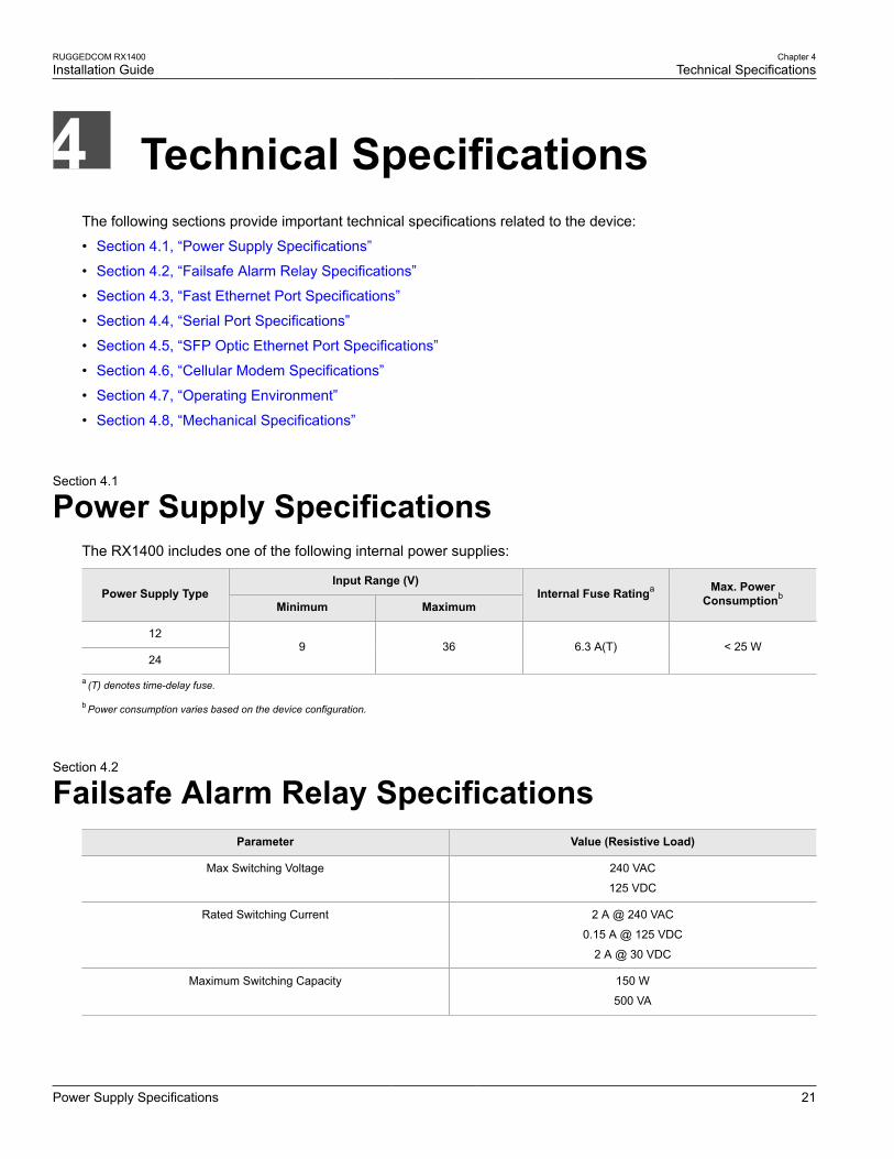
Power Supply SpecificationsThe RX1400 includes one of the following internal power supplies:
Input Range (V)Power Supply Type
Minimum MaximumInternal Fuse Ratinga Max. Power
Consumptionb
12
249 36 6.3 A(T) < 25 W
a (T) denotes time-delay fuse.
b Power consumption varies based on the device configuration.
Section 4.2
Failsafe Alarm Relay SpecificationsParameter Value (Resistive Load)
Max Switching Voltage 240 VAC
125 VDC
Rated Switching Current 2 A @ 240 VAC
0.15 A @ 125 VDC
2 A @ 30 VDC
Maximum Switching Capacity 150 W
500 VA
Chapter 4Technical Specifications
RUGGEDCOM RX1400Installation Guide
22 Fast Ethernet Port Specifications
Section 4.3
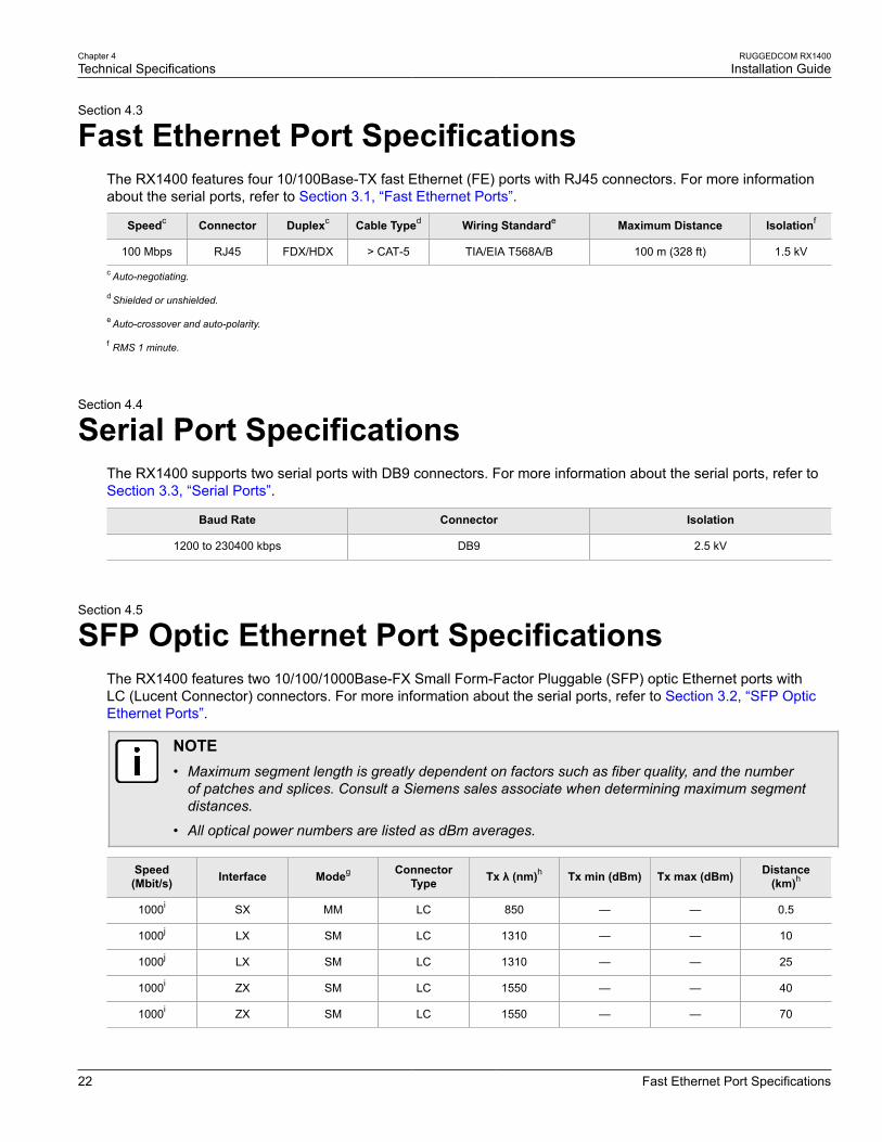
Fast Ethernet Port SpecificationsThe RX1400 features four 10/100Base-TX fast Ethernet (FE) ports with RJ45 connectors. For more informationabout the serial ports, refer to Section 3.1, “Fast Ethernet Ports”.
Speedc Connector Duplexc Cable Typed Wiring Standarde Maximum Distance Isolationf
100 Mbps RJ45 FDX/HDX > CAT-5 TIA/EIA T568A/B 100 m (328 ft) 1.5 kV
c Auto-negotiating.
d Shielded or unshielded.
e Auto-crossover and auto-polarity.
f RMS 1 minute.
Section 4.4
Serial Port SpecificationsThe RX1400 supports two serial ports with DB9 connectors. For more information about the serial ports, refer toSection 3.3, “Serial Ports”.
Baud Rate Connector Isolation
1200 to 230400 kbps DB9 2.5 kV
Section 4.5
SFP Optic Ethernet Port SpecificationsThe RX1400 features two 10/100/1000Base-FX Small Form-Factor Pluggable (SFP) optic Ethernet ports withLC (Lucent Connector) connectors. For more information about the serial ports, refer to Section 3.2, “SFP OpticEthernet Ports”.
NOTE• Maximum segment length is greatly dependent on factors such as fiber quality, and the number
of patches and splices. Consult a Siemens sales associate when determining maximum segmentdistances.
• All optical power numbers are listed as dBm averages.
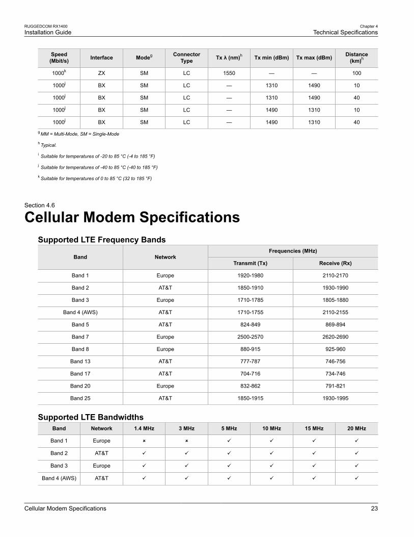
Speed(Mbit/s) Interface Modeg Connector
Type Tx λ (nm)h Tx min (dBm) Tx max (dBm) Distance(km)h
1000i SX MM LC 850 — — 0.5
1000j LX SM LC 1310 — — 10
1000j LX SM LC 1310 — — 25
1000i ZX SM LC 1550 — — 40
1000i ZX SM LC 1550 — — 70
RUGGEDCOM RX1400Installation Guide
Chapter 4Technical Specifications
Cellular Modem Specifications 23
Speed(Mbit/s) Interface Modeg Connector
Type Tx λ (nm)h Tx min (dBm) Tx max (dBm) Distance(km)h
1000k ZX SM LC 1550 — — 100
1000j BX SM LC — 1310 1490 10
1000j BX SM LC — 1310 1490 40
1000j BX SM LC — 1490 1310 10
1000j BX SM LC — 1490 1310 40
g MM = Multi-Mode, SM = Single-Mode
h Typical.
i Suitable for temperatures of -20 to 85 °C (-4 to 185 °F)
j Suitable for temperatures of -40 to 85 °C (-40 to 185 °F)
k Suitable for temperatures of 0 to 85 °C (32 to 185 °F)
Section 4.6
Cellular Modem SpecificationsSupported LTE Frequency Bands
Frequencies (MHz)Band Network
Transmit (Tx) Receive (Rx)
Band 1 Europe 1920-1980 2110-2170
Band 2 AT&T 1850-1910 1930-1990
Band 3 Europe 1710-1785 1805-1880
Band 4 (AWS) AT&T 1710-1755 2110-2155
Band 5 AT&T 824-849 869-894
Band 7 Europe 2500-2570 2620-2690
Band 8 Europe 880-915 925-960
Band 13 AT&T 777-787 746-756
Band 17 AT&T 704-716 734-746
Band 20 Europe 832-862 791-821
Band 25 AT&T 1850-1915 1930-1995
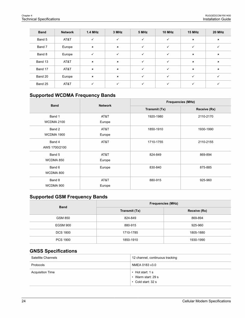
Supported LTE BandwidthsBand Network 1.4 MHz 3 MHz 5 MHz 10 MHz 15 MHz 20 MHz
Band 1 Europe û û ü ü ü ü
Band 2 AT&T ü ü ü ü ü ü
Band 3 Europe ü ü ü ü ü ü
Band 4 (AWS) AT&T ü ü ü ü ü ü
Chapter 4Technical Specifications
RUGGEDCOM RX1400Installation Guide
24 Cellular Modem Specifications
Band Network 1.4 MHz 3 MHz 5 MHz 10 MHz 15 MHz 20 MHz
Band 5 AT&T ü ü ü ü û û
Band 7 Europe û û ü ü ü ü
Band 8 Europe ü ü ü ü û û
Band 13 AT&T û û ü ü û û
Band 17 AT&T û û ü ü û û
Band 20 Europe û û ü ü ü ü
Band 25 AT&T ü ü ü ü ü ü
Supported WCDMA Frequency BandsFrequencies (MHz)
Band NetworkTransmit (Tx) Receive (Rx)
Band 1
WCDMA 2100
AT&T
Europe
1920-1980 2110-2170
Band 2
WCDMA 1900
AT&T
Europe
1850-1910 1930-1990
Band 4
AWS 1700/2100
AT&T 1710-1755 2110-2155
Band 5
WCDMA 850
AT&T
Europe
824-849 869-894
Band 6
WCDMA 800
Europe 830-840 875-885
Band 8
WCDMA 900
AT&T
Europe
880-915 925-960
Supported GSM Frequency BandsFrequencies (MHz)
BandTransmit (Tx) Receive (Rx)
GSM 850 824-849 869-894
EGSM 900 880-915 925-960
DCS 1800 1710-1785 1805-1880
PCS 1900 1850-1910 1930-1990
GNSS SpecificationsSatellite Channels 12 channel, continuous tracking
Protocols NMEA 0183 v3.0
Acquisition Time • Hot start: 1 s• Warm start: 29 s• Cold start: 32 s
RUGGEDCOM RX1400Installation Guide
Chapter 4Technical Specifications
Operating Environment 25
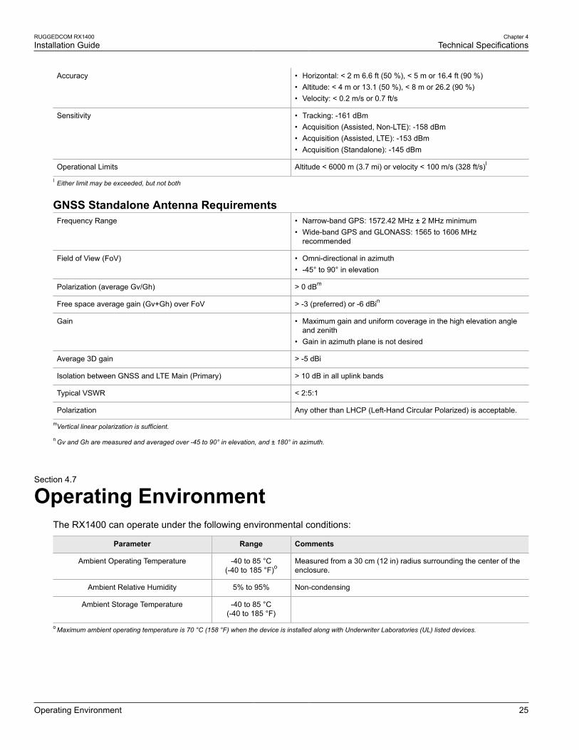
Accuracy • Horizontal: < 2 m 6.6 ft (50 %), < 5 m or 16.4 ft (90 %)• Altitude: < 4 m or 13.1 (50 %), < 8 m or 26.2 (90 %)• Velocity: < 0.2 m/s or 0.7 ft/s
Sensitivity • Tracking: -161 dBm• Acquisition (Assisted, Non-LTE): -158 dBm• Acquisition (Assisted, LTE): -153 dBm• Acquisition (Standalone): -145 dBm
Operational Limits Altitude < 6000 m (3.7 mi) or velocity < 100 m/s (328 ft/s)l
l Either limit may be exceeded, but not both
GNSS Standalone Antenna RequirementsFrequency Range • Narrow-band GPS: 1572.42 MHz ± 2 MHz minimum
• Wide-band GPS and GLONASS: 1565 to 1606 MHzrecommended
Field of View (FoV) • Omni-directional in azimuth• -45° to 90° in elevation
Polarization (average Gv/Gh) > 0 dBm
Free space average gain (Gv+Gh) over FoV > -3 (preferred) or -6 dBin
Gain • Maximum gain and uniform coverage in the high elevation angleand zenith
• Gain in azimuth plane is not desired
Average 3D gain > -5 dBi
Isolation between GNSS and LTE Main (Primary) > 10 dB in all uplink bands
Typical VSWR < 2:5:1
Polarization Any other than LHCP (Left-Hand Circular Polarized) is acceptable.
mVertical linear polarization is sufficient.
n Gv and Gh are measured and averaged over -45 to 90° in elevation, and ± 180° in azimuth.
Section 4.7
Operating EnvironmentThe RX1400 can operate under the following environmental conditions:
Parameter Range Comments
Ambient Operating Temperature -40 to 85 °C(-40 to 185 °F)o
Measured from a 30 cm (12 in) radius surrounding the center of theenclosure.
Ambient Relative Humidity 5% to 95% Non-condensing
Ambient Storage Temperature -40 to 85 °C(-40 to 185 °F)
o Maximum ambient operating temperature is 70 °C (158 °F) when the device is installed along with Underwriter Laboratories (UL) listed devices.
Chapter 4Technical Specifications
RUGGEDCOM RX1400Installation Guide
26 Mechanical Specifications
Section 4.8
Mechanical SpecificationsParameter Value
Dimensions Refer to Chapter 5, Dimension Drawings
Weight 2.5 kg (5.5 lb)
Ingress Protection IP40
Enclosure Aluminum
RUGGEDCOM RX1400Installation Guide
Chapter 5Dimension Drawings
27
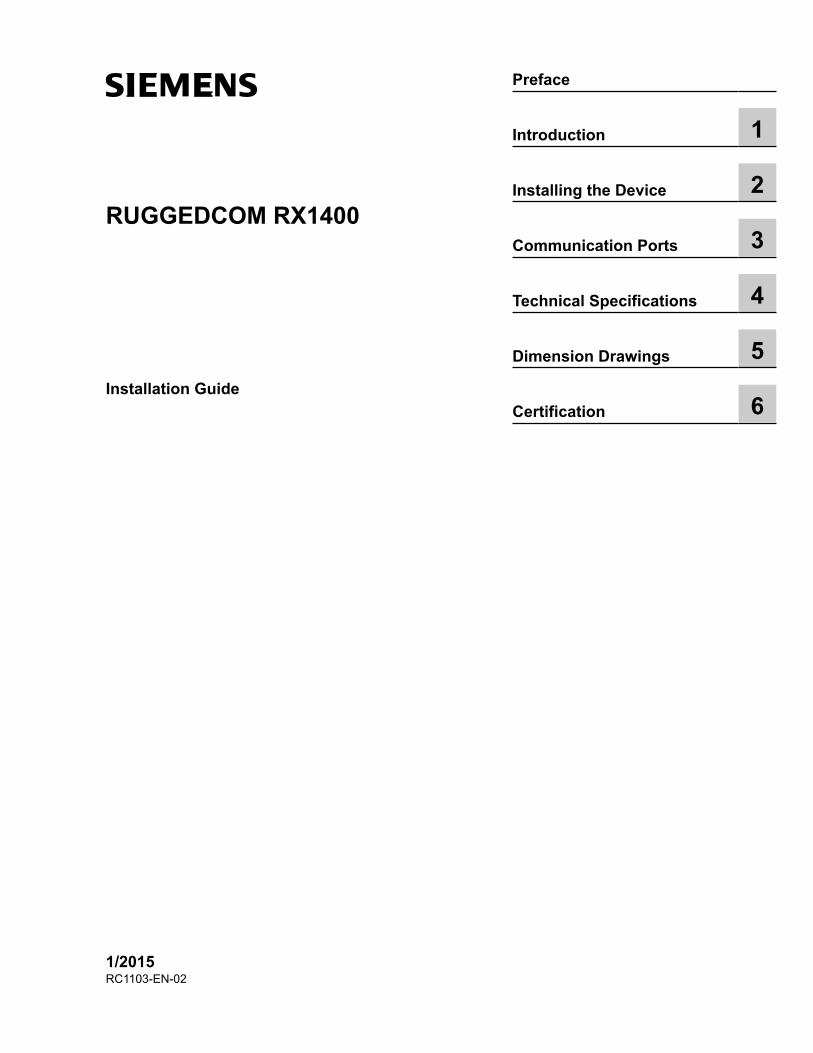
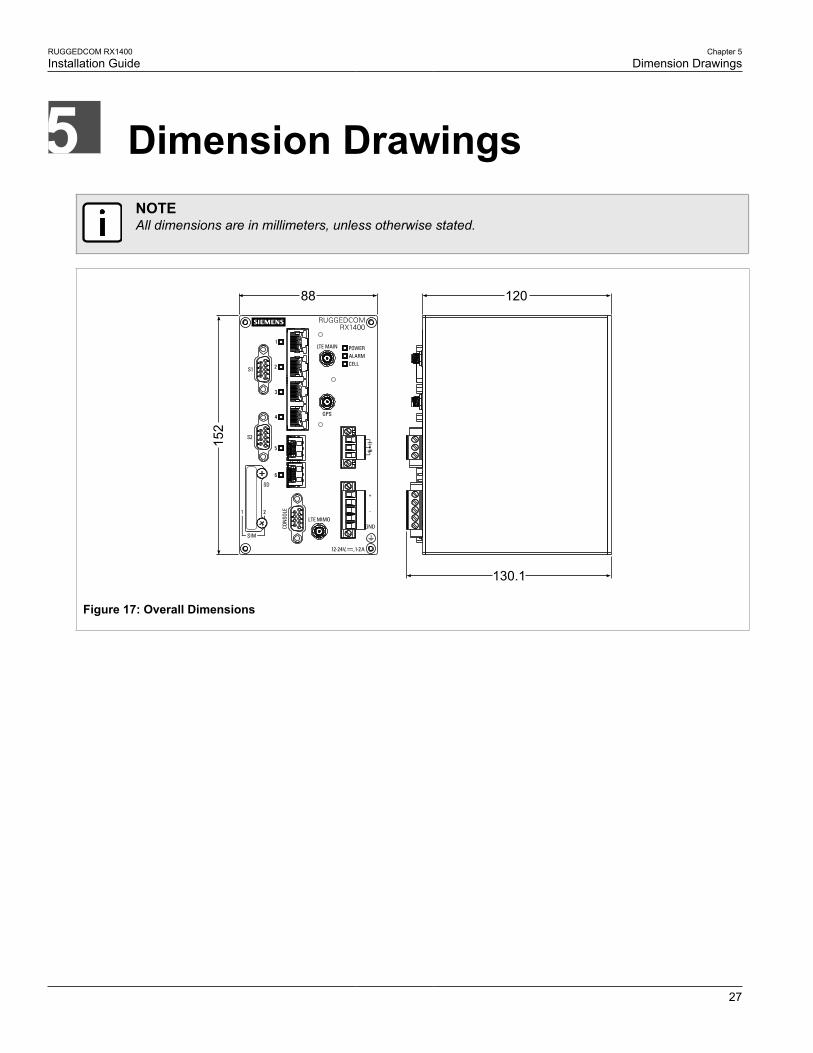
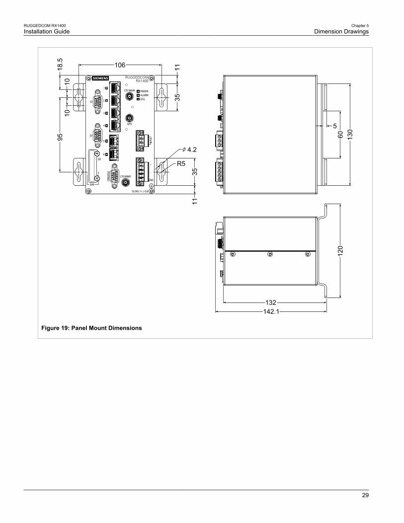
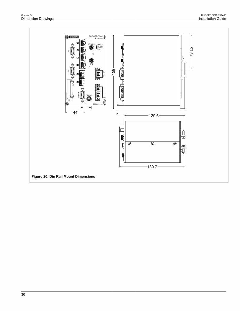
Dimension DrawingsNOTEAll dimensions are in millimeters, unless otherwise stated.
152
88 120
130.1
Figure 17: Overall Dimensions
Chapter 5Dimension Drawings
RUGGEDCOM RX1400Installation Guide
28
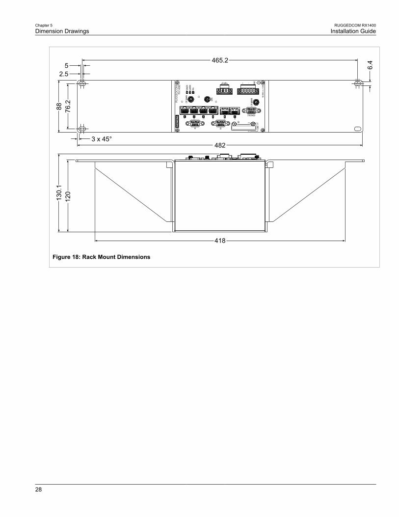
3 x 45°482
76.2
885
2.5
465.2
6.4
418
120
130.
1
Figure 18: Rack Mount Dimensions
RUGGEDCOM RX1400Installation Guide
Chapter 5Dimension Drawings
29
9518
.510
10106 11
35
4.2
35
R5
11
5
60 130
120
132142.1
Figure 19: Panel Mount Dimensions
Chapter 5Dimension Drawings
RUGGEDCOM RX1400Installation Guide
30
129.6715
944
73.1
5
139.7
Figure 20: Din Rail Mount Dimensions
RUGGEDCOM RX1400Installation Guide
Chapter 6Certification
Agency Approvals 31
CertificationThe RX1400 device has been thoroughly tested to guarantee its conformance with recognized standards and hasreceived approval from recognized regulatory agencies.
• Section 6.1, “Agency Approvals”
• Section 6.2, “FCC Compliance”
• Section 6.3, “Industry Canada Compliance”
• Section 6.4, “EMC and Environmental Type Tests”
Section 6.1
Agency ApprovalsAgency Standards Comments
TUV UL 60950-1
CAN/CSA-C22.2 No. 60950-1
Approved
CE EN 60950-1, EN 61000-6-2, EN55022, EN 60825-1, EN 50581
CE Compliance is claimed viaDeclaration of Self Conformity Route
FCC FCC Part 15, Class B Approved
FDA/CDRH 21 CFR Chapter I, Sub-chapter J Laser Eye Safety
ISO ISO9001:2008 Designed and manufactured using anISO9001: 2008 certified quality program
Industry Canada ICES-003
Section 6.2
FCC ComplianceThis equipment has been tested and found to comply with the limits for a Class B digital device pursuant to Part15 of the FCC Rules. These limits are designed to provide reasonable protection against harmful interferencewhen the equipment is operated in a commercial environment.
This equipment generates, uses and can radiate radio frequency energy and, if not installed and used inaccordance with the instruction manual, may cause harmful interference to radio communications. Operation ofthis equipment in a residential area is likely to cause harmful interference in which case the user will be requiredto correct the interference on his own expense.
Chapter 6Certification
RUGGEDCOM RX1400Installation Guide
32 Industry Canada Compliance
Section 6.3
Industry Canada ComplianceCAN ICES-3 (A) / NMB-3 (A)
Section 6.4
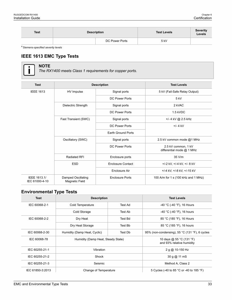
EMC and Environmental Type TestsThe RX1400 has passed the following Electromagnetic Compatibility (EMC) and environmental tests.
IEC 61850-3 EMC Type TestsTest Description Test Levels Severity
Levels
Enclosure Contact +/- 8 kVIEC 61000-4-2 ESD
Enclosure Air +/- 15 kV
4
IEC 61000-4-3 Radiated RFI Enclosure Ports 20 V/m
Signal ports +/- 4 kV @ 2.5 kHz
Notea
DC Power Ports +/- 4 kV
IEC 61000-4-4 Burst (Fast Transient)
Earth Ground Ports +/- 4 kV
Signal ports +/- 4 kV line-to-earth,+/- 2 kV line-to-line
4
IEC 61000-4-5 Surge
DC Power Ports +/- 2 kV line-to-earth,+/- 1 kV line-to-line
3
Signal ports
DC Power Ports
IEC 61000-4-6 Induced (Conducted) RFI
Earth Ground Ports
10 V 3
40 A/m, continuous,1000 A/m for 1 s
NoteaIEC 61000-4-8 Magnetic Field Enclosure Ports
1000 A/m for 1 s 5
IEC 61000-4-29 Voltage Dips and Interrupts DC Power Ports 30% for 0.1 s, 60% for0.1 s, 100% for 0.05 s
IEC 61000-4-18 Damped Oscillatory Wave Slow Damped 2.5 kV common, 100 kHz or 1 MHz 3
Signal ports 30 V Continuous, 300 V for 1sIEC 61000-4-16 Mains Frequency Voltage
DC Power Ports 30 V Continuous, 300 V for 1s
4
IEC 61000-4-17 Ripple on DC Power Supply DC Power Ports 10% 3
Signal ports 2 kVAC (Fail-Safe Relay output)Dielectric Strength
DC Power Ports 1.5 kVDC
IEC 60255-5
HV Impulse Signal ports 5 kV (Fail-Safe Relay output)
RUGGEDCOM RX1400Installation Guide
Chapter 6Certification
EMC and Environmental Type Tests 33
Test Description Test Levels SeverityLevels
DC Power Ports 5 kV
a Siemens-specified severity levels
IEEE 1613 EMC Type Tests
NOTEThe RX1400 meets Class 1 requirements for copper ports.
Test Description Test Levels
Signal ports 5 kV (Fail-Safe Relay Output)HV Impulse
DC Power Ports 5 kV
Signal ports 2 kVACDielectric Strength
DC Power Ports 1.5 kVDC
Signal ports +/- 4 kV @ 2.5 kHz
DC Power Ports
Fast Transient (SWC)
Earth Ground Ports
+/- 4 kV
Signal ports 2.5 kV common mode @1 MHzOscillatory (SWC)
DC Power Ports 2.5 kV common, 1 kVdifferential mode @ 1 MHz
Radiated RFI Enclosure ports 35 V/m
Enclosure Contact +/-2 kV, +/-4 kV, +/- 8 kV
IEEE 1613
ESD
Enclosure Air +/-4 kV, +/-8 kV, +/-15 kV
IEEE 1613.1/IEC 61000-4-10
Damped OscillatingMagnetic Field
Enclosure Ports 100 A/m for 1 s (100 kHz and 1 MHz)
Environmental Type TestsTest Description Test Levels
Cold Temperature Test Ad -40 °C (-40 °F), 16 HoursIEC 60068-2-1
Cold Storage Test Ab -40 °C (-40 °F), 16 hours
Dry Heat Test Bd 85 °C (185 °F), 16 HoursIEC 60068-2-2
Dry Heat Storage Test Bb 85 °C (185 °F), 16 hours
IEC 60068-2-30 Humidity (Damp Heat, Cyclic) Test Db 95% (non-condensing), 55 °C (131 °F), 6 cycles
IEC 60068-78 Humidity (Damp Heat, Steady State) 10 days @ 55 °C (131 °F)and 93% relative humidity
IEC 60255-21-1 Vibration 2 g @ 10-150 Hz
IEC 60255-21-2 Shock 30 g @ 11 mS
IEC 60255-21-3 Seismic Method A, Class 2
IEC 61850-3:2013 Change of Temperature 5 Cycles (-40 to 85 °C or -40 to 185 °F)
Chapter 6Certification
RUGGEDCOM RX1400Installation Guide
34 EMC and Environmental Type Tests
Test Description Test Levels
IEC 60068-1-14:2013