Embed Size (px)
Citation preview
RUGGEDCOM RSG2100
Installation Guide
07/2015
Preface
Introduction 1
Installing Device 2
Communication Ports 3
Technical Specifications 4
Dimension Drawings 5
Certification 6
RC1040-EN-06

RUGGEDCOM RSG2100Installation Guide
ii
Copyright © 2015 Siemens Canada Ltd.
All rights reserved. Dissemination or reproduction of this document, or evaluation and communication of its contents, is not authorizedexcept where expressly permitted. Violations are liable for damages. All rights reserved, particularly for the purposes of patent application ortrademark registration.
This document contains proprietary information, which is protected by copyright. All rights are reserved. No part of this document may bephotocopied, reproduced or translated to another language without the prior written consent of Siemens Canada Ltd..
Disclaimer Of LiabilitySiemens has verified the contents of this manual against the hardware and/or software described. However, deviations between the productand the documentation may exist.
Siemens shall not be liable for any errors or omissions contained herein or for consequential damages in connection with the furnishing,performance, or use of this material.
The information given in this document is reviewed regularly and any necessary corrections will be included in subsequent editions. Weappreciate any suggested improvements. We reserve the right to make technical improvements without notice.
Registered TrademarksROX™, Rugged Operating System On Linux™, CrossBow™ and ELAN™ are trademarks of Siemens Canada Ltd. ROS® is a registeredtrademark of Siemens Canada Ltd.
Other designations in this manual might be trademarks whose use by third parties for their own purposes would infringe the rights of theowner.
Third Party CopyrightsSiemens recognizes the following third party copyrights:
• Copyright © 2004 GoAhead Software, Inc. All Rights Reserved.
Security InformationSiemens provides products and solutions with industrial security functions that support the secure operation of plants, machines, equipmentand/or networks. They are important components in a holistic industrial security concept. With this in mind, Siemens' products and solutionsundergo continuous development. Siemens recommends strongly that you regularly check for product updates.
For the secure operation of Siemens products and solutions, it is necessary to take suitable preventive action (e.g. cell protection concept)and integrate each component into a holistic, state-of-the-art industrial security concept. Third-party products that may be in use should alsobe considered. For more information about industrial security, visit http://www.siemens.com/industrialsecurity.
To stay informed about product updates as they occur, sign up for a product-specific newsletter. For more information, visit http://support.automation.siemens.com.
WarrantySiemens warrants this product for a period of five (5) years from the date of purchase, conditional upon the return to factory for maintenanceduring the warranty term. This product contains no user-serviceable parts. Attempted service by unauthorized personnel shall render allwarranties null and void. The warranties set forth in this article are exclusive and are in lieu of all other warranties, performance guaranteesand conditions whether written or oral, statutory, express or implied (including all warranties and conditions of merchantability and fitness fora particular purpose, and all warranties and conditions arising from course of dealing or usage or trade). Correction of nonconformities in themanner and for the period of time provided above shall constitute the Seller’s sole liability and the Customer’s exclusive remedy for defectiveor nonconforming goods or services whether claims of the Customer are based in contract (including fundamental breach), in tort (includingnegligence and strict liability) or otherwise.
For warranty details, visit www.siemens.com/ruggedcom or contact a Siemens customer service representative.
Contacting SiemensAddressSiemens Canada Ltd.Industry Sector300 Applewood CrescentConcord, OntarioCanada, L4K 5C7
TelephoneToll-free: 1 888 264 0006Tel: +1 905 856 5288Fax: +1 905 856 1995
Webwww.siemens.com/ruggedcom

RUGGEDCOM RSG2100Installation Guide
Table of Contents
iii
Table of ContentsPreface ................................................................................................................ v
Alerts .................................................................................................................................................. vRelated Documents ............................................................................................................................. vAccessing Documentation .................................................................................................................... vTraining .............................................................................................................................................. viCustomer Support .............................................................................................................................. vi
Chapter 1
Introduction .......................................................................................................... 1
1.1 Feature Highlights ........................................................................................................................ 11.2 Description .................................................................................................................................. 2
Chapter 2
Installing Device .................................................................................................. 5
2.1 Mounting the Device .................................................................................................................... 52.1.1 Mounting the Device to a Rack .......................................................................................... 62.1.2 Mounting the Device on a DIN Rail .................................................................................... 72.1.3 Mounting the Device to a Panel ......................................................................................... 7
2.2 Connecting Power ........................................................................................................................ 82.2.1 Connecting AC Power ....................................................................................................... 92.2.2 Connecting DC Power ..................................................................................................... 102.2.3 Wiring Examples ............................................................................................................. 12
2.3 Connecting the Failsafe Alarm Relay ........................................................................................... 142.4 Grounding the Device ................................................................................................................. 152.5 Connecting to the Device ........................................................................................................... 152.6 Cabling Recommendations ......................................................................................................... 16
2.6.1 Protection On Twisted-Pair Data Ports .............................................................................. 172.6.2 Gigabit Ethernet 1000Base-TX Cabling Recommendations ................................................. 17
Chapter 3
Communication Ports ......................................................................................... 19
3.1 Copper Ethernet Ports ................................................................................................................ 203.2 Fiber Optic Ethernet Ports .......................................................................................................... 223.3 SFP Optic Ethernet Ports ........................................................................................................... 22
3.3.1 Installing an SFP Optical Port .......................................................................................... 23

Table of Contents
RUGGEDCOM RSG2100Installation Guide
iv
3.3.2 Removing an SFP Optical Port ......................................................................................... 243.4 GBIC Optic Ethernet Ports .......................................................................................................... 24
3.4.1 Installing a GBIC Optical Port ........................................................................................... 253.4.2 Removing a GBIC Optical Port ......................................................................................... 26
3.5 BNC Ports ................................................................................................................................. 26
Chapter 4
Technical Specifications ..................................................................................... 29
4.1 Power Supply Specifications ....................................................................................................... 294.2 Failsafe Relay Specifications ...................................................................................................... 294.3 Supported Networking Standards ................................................................................................ 304.4 Copper Ethernet Port Specifications ............................................................................................ 30
4.4.1 Copper Fast (10/100 Mbps) Ethernet Port Specifications .................................................... 304.4.2 Copper Gigabit Ethernet (1 Gbps) Port Specifications ........................................................ 31
4.5 Fiber Optic Ethernet Port Specifications ....................................................................................... 314.5.1 10FL Ethernet Optical Specifications ................................................................................ 324.5.2 Fast Ethernet (10/100 Mbps) Optical Specifications ........................................................... 324.5.3 Gigabit Ethernet (1 Gbps) Optical Specifications ................................................................ 33
4.6 Operating Environment ............................................................................................................... 344.7 Mechanical Specifications ........................................................................................................... 34
Chapter 5
Dimension Drawings .......................................................................................... 35
Chapter 6
Certification ........................................................................................................ 39
6.1 Standards Compliance ............................................................................................................... 396.2 Agency Approvals ...................................................................................................................... 396.3 EMI and Environmental Type Tests ............................................................................................. 40

RUGGEDCOM RSG2100Installation Guide
Preface
Alerts v
PrefaceThis guide describes the RUGGEDCOM RUGGEDCOM RSG2100. It describes the major features of the device,installation, commissioning and important technical specifications.
It is intended for use by network technical support personnel who are responsible for the installation,commissioning and maintenance of the device. It is also recommended for use by network and system planners,system programmers, and line technicians.
AlertsThe following types of alerts are used when necessary to highlight important information.
DANGER!DANGER alerts describe imminently hazardous situations that, if not avoided, will result in death orserious injury.
WARNING!WARNING alerts describe hazardous situations that, if not avoided, may result in serious injury and/orequipment damage.
CAUTION!CAUTION alerts describe hazardous situations that, if not avoided, may result in equipment damage.
IMPORTANT!IMPORTANT alerts provide important information that should be known before performing a procedureor step, or using a feature.
NOTENOTE alerts provide additional information, such as facts, tips and details.
Related DocumentsOther documents that may be of interest include:
• ROS User Guide for the RUGGEDCOM RSG2100
Accessing DocumentationThe latest Hardware Installation Guides and Software User Guides for most RUGGEDCOM products areavailable online at www.siemens.com/ruggedcom.

Preface
RUGGEDCOM RSG2100Installation Guide
vi Training
For any questions about the documentation or for assistance finding a specific document, contact a Siemenssales representative.
TrainingSiemens offers a wide range of educational services ranging from in-house training of standard courses onnetworking, Ethernet switches and routers, to on-site customized courses tailored to the customer's needs,experience and application.
Siemens' Educational Services team thrives on providing our customers with the essential practical skills to makesure users have the right knowledge and expertise to understand the various technologies associated with criticalcommunications network infrastructure technologies.
Siemens' unique mix of IT/Telecommunications expertise combined with domain knowledge in the utility,transportation and industrial markets, allows Siemens to provide training specific to the customer's application.
For more information about training services and course availability, visit www.siemens.com/ruggedcom orcontact a Siemens sales representative.
Customer SupportCustomer support is available 24 hours, 7 days a week for all Siemens customers. For technical support orgeneral information, contact Siemens Customer Support through any of the following methods:
OnlineVisit http://www.siemens.com/automation/support-request to submit a Support Request (SR) orcheck on the status of an existing SR.
TelephoneCall a local hotline center to submit a Support Request (SR). To locate a local hotline center, visithttp://www.automation.siemens.com/mcms/aspa-db/en/automation-technology/Pages/default.aspx.
Mobile AppInstall the Industry Online Support app by Siemens AG on any Android, Apple iOS or Windowsmobile device and be able to:
• Access Siemens' extensive library of support documentation, including FAQs and manuals• Submit SRs or check on the status of an existing SR• Contact a local Siemens representative from Sales, Technical Support, Training, etc.• Ask questions or share knowledge with fellow Siemens customers and the support community
RUGGEDCOM RSG2100Installation Guide
Chapter 1Introduction
Feature Highlights 1
IntroductionThe RUGGEDCOM RUGGEDCOM RSG2100 is a rugged, fully managed, modular Ethernet switch specificallydesigned to operate reliably in electrically harsh and climatically demanding utility substation, railway andindustrial environments. The RUGGEDCOM RSG2100’s superior rugged hardware design coupled with theembedded Rugged Operating System (ROS) provides improved system reliability and advanced cyber securityand networking features, making it ideally suited for creating Ethernet networks for mission-critical, real-time,control applications.
The RUGGEDCOM RSG2100’s modular flexibility offers 10BaseFL/100BaseFX/1000BaseX fiber and10/100/1000BaseTX copper port combinations. Optional front or rear mount connectors make the RUGGEDCOMRSG2100 highly versatile for any application and can support multiple fiber connectors (ST, MTRJ, LC, SC)without loss of port density. The RUGGEDCOM RSG2100 is packaged in a rugged galvanized steel enclosurewith industrial grade DIN, panel, or 48 cm (19 in) rack-mount mounting options.
The following sections provide more information about the RUGGEDCOM RSG2100:
• Section 1.1, “Feature Highlights”
• Section 1.2, “Description”
Section 1.1
Feature HighlightsEthernet Ports
• Up to 3 x Gigabit Ethernet ports (copper and fiber)
• Up to 16 x 100Base-FX Fiber Fast Ethernet ports (copper and fiber)
• 2-port modules for tremendous flexibility
• Non-blocking, store and forward switching
• Supports many types of fiber (multimode, single mode, bidirectional single strand)
• Long haul optics allow Gigabit at distances up to 70 km
• Multiple connector types (ST, MTRJ, LC, SC)
Rated for Reliability in Harsh Environments
• Immunity to EMI and heavy electrical surges
• Zero-Packet-Loss™ technology
• -40 to 85 °C (-40 to 185 °F) operating temperature (no fans)
• Conformal coated printed circuit boards (optional)
• 18 AWG galvanized steel enclosure
• Hazardous Location Certification: Class 1 Division 2
Universal Power Supply Options
• Fully integrated, dual-redundant (optional) power supplies
• Universal high-voltage range: 88-300 VDC or 85-264 VAC

Chapter 1Introduction
RUGGEDCOM RSG2100Installation Guide
2 Description
• Screw or pluggable terminal blocks for reliable, maintenance-free connections
• CSA/UL 60950-1 safety approved to 85 °C (185 °F)
Section 1.2
DescriptionThe RUGGEDCOM RSG2100 features various ports, controls and indicator LEDs on the display panel forconnecting, configuring and troubleshooting the device. The display panel can be located on the rear, front or topof the device, depending on the mounting configuration.
3 421
5
7
6
Figure 1: RUGGEDCOM RSG2100
1. Fiber or Copper Ethernet Ports 2. Port Status Indicator LEDs 3. Mode Button 4. RS-232 Serial Console Port (RJ45) 5. DisplayMode Indicator LEDs 6. Alarm Indicator LED 7. Power Module Indicator LEDs
• Communication Ports – Ports for communicating with other devices or accessing the RUGGEDCOM ROSoperating system are described in Chapter 3, Communication Ports.
• Port Status Indicator LEDs – Port status indicator LEDs indicate the operational status of each port,dependent on the currently selected mode.
Mode Color/State Description
Green (Solid) Link detected
Green (Blinking) Link activity
Status
Off No link detected
Green Full duplex mode
Orange Half duplex mode
Duplex
Off No link detected
Green (Solid) 100 Mb/s
Green (Blinking) 1000 Mb/s
Orange (Solid) 10 Mb/s
Speed
Off No link detected
• Display Mode Indicator LEDs – The display mode indicator LEDs indicate the current display mode for theport status indicator LEDs (i.e. Status, Duplex or Speed).

RUGGEDCOM RSG2100Installation Guide
Chapter 1Introduction
Description 3
• Mode button – The Mode button sets the display mode for the port status indicator LEDs (i.e. Status, Duplexor Speed). It can also be used to reset the device if held for 5 seconds.
• Alarm Indicator LED – The alarm indicator LED illuminates when an alarm condition exists.
• Power Module Indicator LEDs – The power module indicator LEDs indicate the status of the power modules.
▪ Green – The power supply is supplying power
▪ Red – Power supply failure
▪ Off – No power supply is installed
• RS-232 Console Port – The serial console port is for interfacing directly with the device and accessing initialmanagement functions. For information about connecting to the device via the serial console port, refer toSection 2.5, “Connecting to the Device”.

RUGGEDCOM RSG2100Installation Guide
Chapter 1Introduction
Description 4

RUGGEDCOM RSG2100Installation Guide
Chapter 2Installing Device
Mounting the Device 5
Installing DeviceThe following sections describe how to install the device, including mounting the device, installing/removingmodules, connecting power, and connecting the device to the network.
DANGER!Electrocution hazard – risk of serious personal injury and/or damage to equipment. Before performingany maintenance tasks, make sure all power to the device has been disconnected and waitapproximately two minutes for any remaining energy to dissipate.
WARNING!Radiation hazard – risk of serious personal injury. This product contains a laser system and isclassified as a CLASS 1 LASER PRODUCT. Use of controls or adjustments or performance ofprocedures other than those specified herein may result in hazardous radiation exposure.
IMPORTANT!This product contains no user-serviceable parts. Attempted service by unauthorized personnel shallrender all warranties null and void.
Changes or modifications not expressly approved by Siemens Canada Ltd. could invalidatespecifications, test results, and agency approvals, and void the user's authority to operate theequipment.
IMPORTANT!This product should be installed in a restricted access location where access can only be gained byauthorized personnel who have been informed of the restrictions and any precautions that must betaken. Access must only be possible through the use of a tool, lock and key, or other means of security,and controlled by the authority responsible for the location.
• Section 2.1, “Mounting the Device”
• Section 2.2, “Connecting Power”
• Section 2.3, “Connecting the Failsafe Alarm Relay”
• Section 2.4, “Grounding the Device”
• Section 2.5, “Connecting to the Device”
• Section 2.6, “Cabling Recommendations”
Section 2.1
Mounting the DeviceThe RUGGEDCOM RSG2100 is designed for maximum mounting and display flexibility. It can be equipped withconnectors that allow it to be installed in a 48 cm (19 in) rack, 35 mm (1.4 in) DIN rail, or directly on a panel.

Chapter 2Installing Device
RUGGEDCOM RSG2100Installation Guide
6 Mounting the Device to a Rack
NOTEFor detailed dimensions of the device with either rack, DIN rail or panel hardware installed, refer toChapter 5, Dimension Drawings.
The following sections describe the various methods of mounting the device:
• Section 2.1.1, “Mounting the Device to a Rack”
• Section 2.1.2, “Mounting the Device on a DIN Rail”
• Section 2.1.3, “Mounting the Device to a Panel”
Section 2.1.1
Mounting the Device to a RackFor rack mount installations, the RUGGEDCOM RSG2100 can be equipped with rack mount adapters pre-installed at the front or rear of the chassis. Additional adapters are provided to further secure the device in high-vibration or seismically active locations.
To secure the device to a standard 48 cm (19 in) rack, do the following:
NOTEThe device can be ordered with the communication ports located at the front or rear of the device.Placing the ports at the rear allows all data and power cabling to be installed and connected at the rearof the rack.
1. Make sure the rack mount adapters are installed on the correct side of the chassis.
NOTEThe chassis features multiple mounting holes, allowing the rack mount adapters to be installed upto 25 mm (1 in) from the face of the device.
1 2
3 3
Figure 2: Rack Mount Adaptors
1. Rear 2. Front 3. Rack Mount Adaptor
2. If required, install adapters on the opposite side of the device to protect from vibrations.
3. Insert the device into the rack.
NOTESince heat within the device is channelled to the enclosure, it is recommended that 1 rack-unitof space, or 44 mm (1.75 in), be kept empty above the device. This allows a small amount ofconvectional airflow.
Forced airflow is not required. However, any increase in airflow will result in a reduction of ambienttemperature and improve the long-term reliability of all equipment mounted in the rack space.

RUGGEDCOM RSG2100Installation Guide
Chapter 2Installing Device
Mounting the Device on a DIN Rail 7
4. Secure the adapters to the rack using the supplied hardware.
Section 2.1.2
Mounting the Device on a DIN RailFor DIN rail installations, the RUGGEDCOM RSG2100 can be equipped with panel/DIN rail adapters pre-installedon each side of the chassis. The adapters allow the device to be slid onto a standard 35 mm (1.4 in) DIN rail.
IMPORTANT!DIN rail mounting is not recommended for constant vibration environments.
To mount the device to a DIN rail, do the following:
1. Align the adapters with the DIN rails and slide the device into place.
2
1
2
3
3
Figure 3: DIN Rail Mounting
1. Panel/DIN Rail Adaptor 2. DIN Rail 3. Screw
2. Install one of the supplied screws on either side of the device to secure the adapters to the DIN rails.
Section 2.1.3
Mounting the Device to a PanelFor panel installations, the RUGGEDCOM RSG2100 can be equipped with panel/DIN rail adapters pre-installedon each side of the chassis. The adapters allow the device to be attached to a panel using screws.
To mount the device to a panel, do the following:
1. Place the device against the panel and align the adapters with the mounting holes.

Chapter 2Installing Device
RUGGEDCOM RSG2100Installation Guide
8 Connecting Power
21
1
Figure 4: Panel Mounting
1. Screw 2. Panel/DIN Rail Adaptor
2. Install the supplied screws to secure the adapters to the panel.
Section 2.2
Connecting PowerThe RUGGEDCOM RSG2100 supports single or dual redundant AC and/or DC power supplies. The use of twopower modules is recommended to provide redundancy and load balancing.
The RUGGEDCOM RSG2100 can be equipped with either a screw-type or pluggable terminal block, whichprovides power to both power supplies. The screw-type terminal block is installed using Phillips screws andcompression plates, allowing either bare wire connections or crimped terminal lugs. Use #6 size ring lugs forsecure, reliable connections under severe shock or vibration.
NOTE• For maximum redundancy in a dual power supply configuration, use two independent power
sources.
• Use only #16 gage copper wiring when connecting terminal blocks.
• For 100-240 VAC rated equipment, an appropriately rated AC circuit breaker must be installed.
• A circuit breaker is not required for 12, 24 or 48 VDC rated power supplies.
• It is recommended to provide a separate circuit breaker for each power supply module.

RUGGEDCOM RSG2100Installation Guide
Chapter 2Installing Device
Connecting AC Power 9
• Equipment must be installed according to applicable local wiring codes and standards.
The following sections describe how to connect power to the device:
• Section 2.2.1, “Connecting AC Power”
• Section 2.2.2, “Connecting DC Power”
• Section 2.2.3, “Wiring Examples”
Section 2.2.1
Connecting AC PowerTo connect a high AC power supply to the device, do the following:
CAUTION!Electrical hazard – risk of damage to equipment. Do not connect AC power cables to terminals for DCpower. Damage to the power supply may occur.
CAUTION!Electrical hazard – risk of damage to equipment. Before testing the dielectric strength (HIPOT) in thefield, remove the metal jumper. This metal jumper connects transient suppression circuitry to chassisground and must be removed in order to avoid damage to transient suppression circuitry during testing.
NOTEThe terminal block is divided into separate terminals for each internal power supply. Make sure toconnect the external power supply to the appropriate terminals.
NOTEThe screw-type terminal block is installed using Phillips screws and compression plates, allowing eitherbare wire connections or crimped terminal lugs. Use #6 size ring lugs for secure, reliable screws, whichmust be removed to make connections.
1. Remove the terminal block cover.
2. If a screw-type terminal block is installed, remove the screws from the appropriate terminals. Use thesescrews along with #6 ring lugs to secure the wires to the terminal block.
3. Connect the positive wire from the power source to the positive/live (+/L) terminal on the terminal block. Formore information, refer to Section 2.2.3, “Wiring Examples”.

Chapter 2Installing Device
RUGGEDCOM RSG2100Installation Guide
10 Connecting DC Power
4
21
34
6
5
7
4
6
5
3
6
5
7
4
6
5
Figure 5: Terminal Block Wiring
1. Screw-Type Terminal Block 2. Pluggable Terminal Block 3. Jumper 4. Positive/Live (+/L) Terminal 5. Negative/Neutral (-/N)Terminal (-/N) 6. Surge Ground Terminal 7. Chassis Ground Terminal
4. Connect the negative wire from the power source to the negative/neutral (-/N) terminal on the terminal block.For more information, refer to Section 2.2.3, “Wiring Examples”.
5. Install the supplied metal jumper between terminals 2, 4 and 6 to connect the surge ground terminals to thechassis ground terminal. The surge ground terminals are used as the ground conductor for all surge andtransient suppression circuitry internal to the unit.
6. Connect the ground terminal on the power source to the chassis ground terminal on the device. For moreinformation, refer to Section 2.4, “Grounding the Device”
DANGER!Electrocution hazard – risk of death, serious personal injury and/or damage to the device. Makesure the supplied terminal block cover is always installed before the device is powered.
7. Install the terminal block cover.
Section 2.2.2
Connecting DC PowerTo connect a high or low DC power supply to the device, do the following:
CAUTION!Electrical hazard – risk of damage to equipment. Before testing the dielectric strength (HIPOT) in thefield, remove the metal jumper. This metal jumper connects transient suppression circuitry to chassisground and must be removed in order to avoid damage to transient suppression circuitry during testing.
NOTEThe terminal block is divided into separate terminals for each internal power supply. Make sure toconnect the external power supply to the appropriate terminals.

RUGGEDCOM RSG2100Installation Guide
Chapter 2Installing Device
Connecting DC Power 11
NOTEThe screw-type terminal block is installed using Phillips screws and compression plates, allowing eitherbare wire connections or crimped terminal lugs. Use #6 size ring lugs for secure, reliable screws, whichmust be removed to make connections.
1. Remove the terminal block cover.
2. If a screw-type terminal block is installed, remove the screws from the appropriate terminals. Use thesescrews along with #6 ring lugs to secure the wires to the terminal block.
3. Connect the positive wire from the power source to the positive/live (+/L) terminal on the terminal block. Formore information, refer to Section 2.2.3, “Wiring Examples”.
4
21
34
6
5
7
4
6
5
3
6
5
7
4
6
5
Figure 6: Terminal Block Wiring
1. Screw-Type Terminal Block 2. Pluggable Terminal Block 3. Jumper 4. Positive/Live (+/L) Terminal 5. Negative/Neutral (-/N)Terminal (-/N) 6. Surge Ground Terminal 7. Chassis Ground Terminal
4. Connect the negative wire from the power source to the negative/neutral (-/N) terminal on the terminal block.For more information, refer to Section 2.2.3, “Wiring Examples”.
5. Install the supplied metal jumper between terminals 2, 4 and 6 to connect the surge ground terminals to thechassis ground terminal. The surge ground terminals are used as the ground conductor for all surge andtransient suppression circuitry internal to the unit.
6. Connect the ground terminal on the power source to the chassis ground terminal on the device. For moreinformation, refer to Section 2.4, “Grounding the Device”
DANGER!Electrocution hazard – risk of death, serious personal injury and/or damage to the device. Makesure the supplied terminal block cover is always installed before the device is powered.
7. Install the terminal block cover.

Chapter 2Installing Device
RUGGEDCOM RSG2100Installation Guide
12 Wiring Examples
Section 2.2.3
Wiring ExamplesThe following illustrate how to connect power to single and dual power supplies.
Figure 7: Single AC Power Supply
Figure 8: Single DC Power Supply

RUGGEDCOM RSG2100Installation Guide
Chapter 2Installing Device
Wiring Examples 13
Figure 9: Dual AC Power Supply
Figure 10: Dual DC Power Supply
Chapter 2Installing Device
RUGGEDCOM RSG2100Installation Guide
14 Connecting the Failsafe Alarm Relay
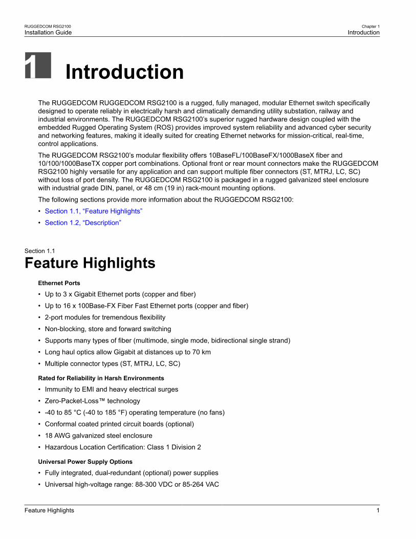
Figure 11: Dual AC/DC Power Supply
Section 2.3
Connecting the Failsafe Alarm RelayThe failsafe relay can be configured to latch based on alarm conditions. The NO (Normally Open) contact isclosed when the unit is powered and there are no active alarms. If the device is not powered or if an active alarmis configured, the relay opens the NO contact and closes the NC (Normally Closed) contact.
NOTEControl of the failsafe relay output is configurable through ROS. One common application for this relayis to signal an alarm if a power failure occurs. For more information, refer to the ROS User Guide forthe RUGGEDCOM RSG2100.
The following shows the proper relay connections.

RUGGEDCOM RSG2100Installation Guide
Chapter 2Installing Device
Grounding the Device 15
1 3
2
Figure 12: Failsafe Alarm Relay Wiring
1. Normally Open 2. Common 3. Normally Closed
Section 2.4
Grounding the DeviceThe RUGGEDCOM RSG2100 chassis ground terminal uses a #6-32 screw. It is recommended to terminate theground connection with a #6 ring lug and torque it to 1.7 N·m (15 lbf·in).
2
1
3
Figure 13: Chassis Ground Connection
1. Stainless Steel Stud 2. #6-32 Screw 3. #6 Ring Lug
Section 2.5
Connecting to the DeviceThe following describes the various methods for accessing the ROS console and Web interfaces on the device.For more detailed instructions, refer to the ROS User Guide for the RUGGEDCOM RSG2100.

Chapter 2Installing Device
RUGGEDCOM RSG2100Installation Guide
16 Cabling Recommendations
RS232 Console PortConnect a PC or terminal directly to the RS232 console port to access the boot-time control and ROS interfaces.The console port provides access to ROS's console and Web interfaces.
IMPORTANT!The console port is intended to be used only as a temporary connection during initial configuration ortroubleshooting.
Connection to the console port is made using an RJ45-to-DB9 console cable. The following is the pin-out for theconsole port:
18
Figure 14: RJ45 Console Port Pin Configuration
Pin
RJ45Male
DB9Female
Name Description Comment
1 6 DSRa Data Set Ready
2 1 DCDa Carrier Detect Reserved (DoNot Connect)
3 4 DTRa Data TerminalReady
4 5 GND Signal Ground
5 2 RxD Receive Data(to DTE)
6 3 TxD Transmit Data(from DTE)
7 8 CTSb Clear to Send
8 7 RTSb Read to Send
1 9 RIc Ring Indicator
a The DSR, DCD and DTR pins are connected together internally.
b The CTS and RTS pins are connected together internally.
c RI is not connected.
Communication PortsConnect any of the available Ethernet ports on the device to a management switch and access the ROS consoleand Web interfaces via the device's IP address. For more information about available ports, refer to Chapter 3,Communication Ports.
Section 2.6
Cabling RecommendationsBefore connecting the device, be aware of the recommendations and considerations outlined in the followingsections:
• Section 2.6.1, “Protection On Twisted-Pair Data Ports”
• Section 2.6.2, “Gigabit Ethernet 1000Base-TX Cabling Recommendations”

RUGGEDCOM RSG2100Installation Guide
Chapter 2Installing Device
Protection On Twisted-Pair Data Ports 17
Section 2.6.1
Protection On Twisted-Pair Data PortsSiemens does not recommend the use of copper cabling of any length for critical, real-time substation automationapplications. All copper Ethernet ports on RUGGEDCOM products include transient suppression circuitryto protect against damage from electrical transients and conform with IEC 61850-3 and IEEE 1613 Class 1standards. This means that during a transient electrical event, communications errors or interruptions may occur,but recovery is automatic.
Siemens also does not recommend using copper Ethernet ports to interface with devices in the field acrossdistances that could produce high levels of ground potential rise (i.e. greater than 2500 V), during line-to-groundfault conditions.
Section 2.6.2
Gigabit Ethernet 1000Base-TX Cabling RecommendationsThe IEEE 802.3ab Gigabit Ethernet standard defines 1000 Mbit/s Ethernet communications over distances of upto 100 m (328 ft) using all 4 pairs in category 5 (or higher) balanced, unshielded twisted-pair cabling. For wiringguidelines, system designers and integrators should refer to the Telecommunications Industry Association (TIA)TIA/EIA-568-A wiring standard that characterizes minimum cabling performance specifications required for properGigabit Ethernet operation. For reliable, error-free data communication, new and pre-existing communicationpaths should be verified for TIA/EIA-568-A compliance.
The following table summarizes the relevant cabling standards:
Cabling Category 1000Base-TX Compliant Required Action
< 5 No New wiring infrastructure required.
5 Yes Verify TIA/EIA-568-A compliance.
5e Yes No action required. New installations should be designed with Category 5e or higher.
6 Yes No action required.
> 6 Yes Connector and wiring standards to be determined.
Follow these recommendations for copper data cabling in high electrical noise environments:
• Data cable lengths should be as short as possible, preferably 3 m (10 ft) in length. Copper data cables shouldnot be used for inter-building communications.
• Power and data cables should not be run in parallel for long distances, and should be installed in separateconduits. Power and data cables should intersect at 90° angles when necessary to reduce inductive coupling.
• Shielded/screened cabling can be used when required. Care should be taken to avoid the creation of groundloops with shielded cabling.
RUGGEDCOM RSG2100Installation Guide
Chapter 2Installing Device
Gigabit Ethernet 1000Base-TX CablingRecommendations 18

RUGGEDCOM RSG2100Installation Guide
Chapter 3Communication Ports
19
Communication PortsThe RUGGEDCOM RSG2100 can be equipped with various types of communication ports to enhance its abilitiesand performance.
3
4
1
2
5
6
7
8
9
10
Figure 15: Port Assignment
Each type of module has a specific location in the RUGGEDCOM RSG2100 chassis:
• Slots 1 to 4 support any combination of fixed fiber or copper Ethernet connectors up to 100 Mbps
• Slot 5 supports a pair of fixed 1 Gbps ports
• Slot 6 supports a single expansion port of any type
• Slots 7 to 10 support any combination of two-port fiber or copper Ethernet modules
The exact configuration of the device can be determined by reading the factory data file through the ROS userinterface. For more information about how to read the factory data file, refer to the ROS User Guide for theRUGGEDCOM RSG2100.
Each communication port is equipped with an LED that indicates the link/activity state of the port.
1
Figure 16: Port LEDs1. Port LED
LED State Description
Green (Solid) Link established
Green (Blinking) Link activity
Off No link detected
The following sections describe the available communication ports:
• Section 3.1, “Copper Ethernet Ports”
• Section 3.2, “Fiber Optic Ethernet Ports”
• Section 3.3, “SFP Optic Ethernet Ports”

Chapter 3Communication Ports
RUGGEDCOM RSG2100Installation Guide
20 Copper Ethernet Ports
• Section 3.4, “GBIC Optic Ethernet Ports”
Section 3.1
Copper Ethernet PortsThe RUGGEDCOM RSG2100 supports several 10/100/1000Base-TX Ethernet ports that allow connection tostandard Category 5 (CAT-5) unshielded twisted-pair (UTP) cables with either RJ45 or Micro-D male connectors.The RJ45 and Micro-D connectors are directly connected to the chassis ground on the device and can acceptCAT-5 shielded twisted-pair (STP) cables.
WARNING!Electric shock hazard – risk of serious personal injury and/or equipment interference. If shieldedcables are used, make sure the shielded cables do not form a ground loop via the shield wire and theRJ45 receptacles at either end. Ground loops can cause excessive noise and interference, but moreimportantly, create a potential shock hazard that can result in serious injury.
Figure 17: 1 x 10/100/1000Tx with RJ45 Ports (1CG01) Figure 18: 2 x 10/100/1000Tx with RJ45 Ports (CG01)
Figure 19: 1 x 10/100/1000Tx with Micro-D Ports(1CG02)
Figure 20: 2 x 10/100/1000Tx with Micro-D Ports(CG02)
Figure 21: 2 x 10/100Tx with RJ45 Ports (TX01) Figure 22: 2 x 10/100Tx with Micro-D Ports (TX02)
RXTX RXTX
Figure 23: 2x 1000Tx SFP with RJ45 Ports (CG55)
Each port features an LED that indicates the state of the port.

RUGGEDCOM RSG2100Installation Guide
Chapter 3Communication Ports
Copper Ethernet Ports 21
State Description
Yellow (Solid) Link established
Yellow (Blinking) Link activity
Off No link detected
The following are the pin-out descriptions for the RJ45 and Micro-D connectors:
18
Figure 24: RJ45 Ethernet Port Pin Configuration
NamePin
10/100Base-TX 1000Base-TXDescription
1 RX+ BI_DB+ Receive Data+or Bi-Directional
2 RX- BI_DB- Receive Data-or Bi-Directional
3 TX+ BI_DA+ Transmit Data+or Bi-Directional
4 Reserved (Do Not Connect)
5 Reserved (Do Not Connect)
6 TX- BI_DA- Transmit Data-or Bi-Directional
7 Reserved (Do Not Connect)
8 Reserved (Do Not Connect)
1
6
Figure 25: Micro-D 10/100Base-TX Port PinConfiguration
Pin 10/100Base-TX 1000Base-TX
1 RX+ A+
2 Reserved (DoNot Connect)
C+
3 Reserved (Do Not Connect)
4 Reserved (DoNot Connect)
D+
5 TX+ B+
6 RX- A-
7 Reserved (DoNot Connect)
C-
8 Reserved (DoNot Connect)
D-
9 TX- B-
For specifications on the available copper Ethernet ports, refer to Section 4.4, “Copper Ethernet PortSpecifications”.
Chapter 3Communication Ports
RUGGEDCOM RSG2100Installation Guide
22 Fiber Optic Ethernet Ports
Section 3.2
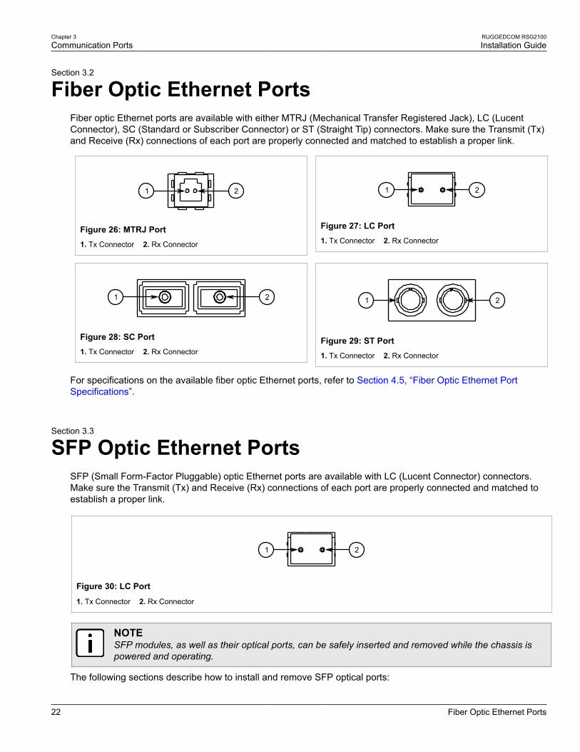
Fiber Optic Ethernet PortsFiber optic Ethernet ports are available with either MTRJ (Mechanical Transfer Registered Jack), LC (LucentConnector), SC (Standard or Subscriber Connector) or ST (Straight Tip) connectors. Make sure the Transmit (Tx)and Receive (Rx) connections of each port are properly connected and matched to establish a proper link.
21
Figure 26: MTRJ Port1. Tx Connector 2. Rx Connector
21
Figure 27: LC Port1. Tx Connector 2. Rx Connector
21
Figure 28: SC Port1. Tx Connector 2. Rx Connector
21
Figure 29: ST Port1. Tx Connector 2. Rx Connector
For specifications on the available fiber optic Ethernet ports, refer to Section 4.5, “Fiber Optic Ethernet PortSpecifications”.
Section 3.3
SFP Optic Ethernet PortsSFP (Small Form-Factor Pluggable) optic Ethernet ports are available with LC (Lucent Connector) connectors.Make sure the Transmit (Tx) and Receive (Rx) connections of each port are properly connected and matched toestablish a proper link.
21
Figure 30: LC Port
1. Tx Connector 2. Rx Connector
NOTESFP modules, as well as their optical ports, can be safely inserted and removed while the chassis ispowered and operating.
The following sections describe how to install and remove SFP optical ports:

RUGGEDCOM RSG2100Installation Guide
Chapter 3Communication Ports
Installing an SFP Optical Port 23
• Section 3.3.1, “Installing an SFP Optical Port”
• Section 3.3.2, “Removing an SFP Optical Port”
Section 3.3.1
Installing an SFP Optical PortTo install an SFP optical port, do the following:
CAUTION!Electrical hazard – risk of damage to equipment. Use only components certified by Siemens withRUGGEDCOM products. Damage to the module and device may occur if compatibility and reliabilityhave not been properly assessed.
CAUTION!Electrical hazard – risk of damage to equipment. Make sure all electrostatic energy is dissipatedbefore installing or removing components from the device. An electrostatic discharge (ESD) can causeserious damage to the component once it is outside the chassis.
1. Make sure all potential electrostatic build-up has been properly discharged to prevent electrostaticdischarges (ESD). This can be accomplished by wearing an ESD wrist strap or by touching Earth or thechassis ground.
2. Remove the dust cover from the port opening in the module.
CAUTION!Mechanical hazard – risk of component damage. SFP optical ports are designed to insert in onlyone orientation. Do not force the port into the module.
3. Remove the port from its packaging.
4. Insert the port into the module and swing the bail-latch up to lock it in place.
2
1
Figure 31: Installing an SFP Optical Port (Typical)
1. SFP Optical Port 2. Metal Bail-Latch
5. Remove the dust cover from the port.
6. Connect a cable to the port and test the connection.

Chapter 3Communication Ports
RUGGEDCOM RSG2100Installation Guide
24 Removing an SFP Optical Port
Section 3.3.2
Removing an SFP Optical PortTo remove an SFP optical port, do the following:
CAUTION!Electrical hazard – risk of damage to equipment. Make sure all electrostatic energy is dissipated beforeperforming installing or removing components from the device. An electrostatic discharge (ESD) cancause serious damage to the component once it is outside the chassis.
1. Make sure all potential electrostatic build-up has been properly discharged to prevent electrostaticdischarges (ESD). This can be accomplished by wearing an ESD wrist strap or by touching Earth or thechassis ground.
2. Disconnect the cable from the port.
3. Swing the metal bail-latch down and pull the port from the module.
2
1
Figure 32: Removing an SFP Optical Port (Typical)
1. SFP Optical Port 2. Metal Bail-Latch
4. Store the port in an ESD-safe bag or other suitable ESD-safe environment, free from moisture and stored atthe proper temperature (-40 to 85 °C or -40 to 185 °F).
5. Insert a plug in the empty port opening to prevent the ingress of dust and dirt.
Section 3.4
GBIC Optic Ethernet PortsGBIC (Gigabit Interface Converter) optic Ethernet ports are available with SC (Standard or Subscriber Connector)connectors.
21
Figure 33: SC Port
1. Tx Connector 2. Rx Connector
The following sections describe how to install and remove GBIC optical ports:
• Section 3.4.1, “Installing a GBIC Optical Port”

RUGGEDCOM RSG2100Installation Guide
Chapter 3Communication Ports
Installing a GBIC Optical Port 25
• Section 3.4.2, “Removing a GBIC Optical Port”
Section 3.4.1
Installing a GBIC Optical PortTo install a GBIC optical port, do the following:
CAUTION!Electrical hazard – risk of damage to equipment. Use only components certified by Siemens withRUGGEDCOM products. Damage to the module and device may occur if compatibility and reliabilityhave not been properly assessed.
CAUTION!Electrical hazard – risk of damage to equipment. Make sure all electrostatic energy is dissipatedbefore installing or removing components from the device. An electrostatic discharge (ESD) can causeserious damage to the component once it is outside the chassis.
1. Make sure all potential electrostatic build-up has been properly discharged to prevent electrostaticdischarges (ESD). This can be accomplished by wearing an ESD wrist strap or by touching Earth or thechassis ground.
2. Remove the dust cover from the port opening in the module.
CAUTION!Mechanical hazard – risk of component damage. GBIC optical ports are designed to insert in onlyone orientation. Do not force the port into the module.
3. Remove the port from its packaging.
4. Squeeze the latches on either side of the port and insert the port into the module.
2
1
3
Figure 34: Installing a GBIC Optical Port
1. GBIC Optical Port Module 2. GBIC Optical Port 3. Locking Latch
5. Release the latches and make sure the module is locked in place.
6. Remove the dust cover from the port.
7. Connect a cable to the port and test the connection.
Chapter 3Communication Ports
RUGGEDCOM RSG2100Installation Guide
26 Removing a GBIC Optical Port
Section 3.4.2
Removing a GBIC Optical PortTo remove an GBIC optical port, do the following:
CAUTION!Electrical hazard – risk of damage to equipment. Make sure all electrostatic energy is dissipated beforeperforming installing or removing components from the device. An electrostatic discharge (ESD) cancause serious damage to the component once it is outside the chassis.
1. Make sure all potential electrostatic build-up has been properly discharged to prevent electrostaticdischarges (ESD). This can be accomplished by wearing an ESD wrist strap or by touching Earth or thechassis ground.
2. Disconnect the cable from the port.
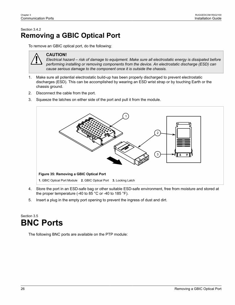
3. Squeeze the latches on either side of the port and pull it from the module.
2
1
3
Figure 35: Removing a GBIC Optical Port
1. GBIC Optical Port Module 2. GBIC Optical Port 3. Locking Latch
4. Store the port in an ESD-safe bag or other suitable ESD-safe environment, free from moisture and stored atthe proper temperature (-40 to 85 °C or -40 to 185 °F).
5. Insert a plug in the empty port opening to prevent the ingress of dust and dirt.
Section 3.5
BNC PortsThe following BNC ports are available on the PTP module:

RUGGEDCOM RSG2100Installation Guide
Chapter 3Communication Ports
BNC Ports 27
1 2 4 5
3
Figure 36: PTP Module1. AM OUT Port 2. TTL OUT Port 3. Sync LED 4. TTL INPort 5. GPS IN Port
Port Function
AM IN AM-level IRIG-B signalinput, software enabled
TTL OUT IRIG-B PWM or 1 PPS signaloutput, software selectable
TTL IN TTL-level IRIG-B PWM signal input
GPS IN GPS antenna input
Inputs are controlled by RUGGEDCOM ROS and only one can be active at any time. For information aboutactivating an input, refer to the RUGGEDCOM ROS User Guide for the RUGGEDCOM RSG2100.
The color of the Sync LED on the front panel of the PTP module indicates the status of the incoming timingsignal:
• Green – Signal locked
• Amber/Yellow – Holdover (GPS lock has been achieved, but the receiver no longer sees the minimum numberof required satellites)
• Red – Error
• Off – No signal detected

RUGGEDCOM RSG2100Installation Guide
Chapter 3Communication Ports
BNC Ports 28

RUGGEDCOM RSG2100Installation Guide
Chapter 4Technical Specifications
Power Supply Specifications 29
Technical SpecificationsThe following sections provide important technical specifications related to the device and available modules:
• Section 4.1, “Power Supply Specifications”
• Section 4.2, “Failsafe Relay Specifications”
• Section 4.3, “Supported Networking Standards”
• Section 4.4, “Copper Ethernet Port Specifications”
• Section 4.5, “Fiber Optic Ethernet Port Specifications”
• Section 4.6, “Operating Environment”
• Section 4.7, “Mechanical Specifications”
Section 4.1
Power Supply SpecificationsInput Range
Power Supply TypeMinimum Maximum
Internal Fuse Ratingab Maximum PowerConsumptionc
24 VDC 10 VDC 36 VDC 6.3 A(F)
48 VDC 36 VDC 72 VDC 3.15 A(T)
HI (125/250 VDC)d 88 VDC 300 VDC 2 A(T)
HI (110/230 VAC)d 85 VAC 264 VAC 2 A(T)
28 W
a (F) denotes fast-acting fuse
b (T) denotes time-delay fuse.
c Power consumption varies based on configuration. 10/100Base-TX ports consume roughly 1 W less than fiber optic ports.
d The HI power supply is the same power supply for both AC and DC.
Section 4.2
Failsafe Relay SpecificationsParameter Value (Resistive Load)
Max Switching Voltage 240 VAC, 125 VDC
Rated Switching Current 2 A @ 240 VAC, 0.15 A @ 125 VDC, 2 A @ 30 VDC
Maximum Switching Capacity 150 W, 500 VA

Chapter 4Technical Specifications
RUGGEDCOM RSG2100Installation Guide
30 Supported Networking Standards
Section 4.3
Supported Networking StandardsStandard 10 Mbps Ports 100 Mbps Ports 1000 Mbps
Ports Notes
IEEE 802.3 ü 10BaseT/10BaseFL
IEEE 802.3u ü 100BaseTX/100BaseFX
IEEE 802.3x ü ü ü Flow Control
IEEE 802.3z ü 1000BaseLX
IEEE 802.3ab ü 1000BaseTx
IEEE 802.3ad ü Link Aggregation
IEEE 802.1D ü ü ü MAC Bridges
IEEE 802.1D ü ü ü Spanning Tree Protocol (STP)
IEEE 802.1p ü ü ü Class of Service (CoS)
IEEE 802.1Q ü ü ü VLAN (Virtual LAN) Tagging
IEEE 802.1w ü ü ü Rapid Spanning Tree Protocol (RSTP)
IEEE 802.1x ü ü ü Port-Based Network Access Control
IEEE802.1Q-2005
(formerly 802.1s)
ü ü ü Multiple Spanning Tree Protocol (MSTP)
Section 4.4
Copper Ethernet Port SpecificationsThe following details the specifications for copper Ethernet ports that can be ordered with the RUGGEDCOMRSG2100.
Section 4.4.1
Copper Fast (10/100 Mbps) Ethernet Port Specifications
Connector Duplexe Cable Typef Wiring Standardg MaximumDistanceh Isolationi
RJ45 FDX/HDX > CAT-5 TIA/EIA T568A/B 100 m (328 ft) 1.5 kV
micro-D FDX/HDX > CAT-5 TIA/EIA T568A/B 100 m (328 ft) 1.5 kV
e Auto-Negotiating
f Shielded or unshielded.
g Auto-crossover and auto-polarity.
h Typical distance. Dependent on the number of connectors and splices.

RUGGEDCOM RSG2100Installation Guide
Chapter 4Technical Specifications
Copper Gigabit Ethernet (1 Gbps) Port Specifications 31
i RMS 1 minute.
Section 4.4.2
Copper Gigabit Ethernet (1 Gbps) Port SpecificationsNOTE• Maximum segment length is greatly dependent on factors such as fiber quality, and the number
of patches and splices. Consult a Siemens sales associate when determining maximum segmentdistances.
• All optical power numbers are listed as dBm averages.
• F51 transceivers are rated for -40 to 85 °C (-40 to 185 °F).
Fixed Gigabit TransceiversConnector Duplexj Cable Typek Wiring Standardl Maximum
Distancem Isolationn
RJ45 FDX/HDX > CAT-5 TIA/EIA T568A/B 100 m (328 ft) 1.5 kV
micro-D FDX/HDX > CAT-5 TIA/EIA T568A/B 100 m (328 ft) 1.5 kV
j Auto-Negotiating
k Shielded or unshielded.
l Auto-crossover and auto-polarity.
mTypical distance. Dependent on the number of connectors and splices.
n RMS 1 minute.
SFP Gigabit TransceiversConnector Duplexo Cable Typep Wiring Standardq Maximum Distance Isolationr
RJ45 FDX/HDX > CAT-5 TIA/EIA T568A/B 100 m (328 ft) 1.5 kV
o Auto-Negotiating
p Shielded or unshielded.
q Auto-crossover and auto-polarity.
r RMS 1 minute.
Section 4.5
Fiber Optic Ethernet Port SpecificationsThe following sections list specifications of the optical transceivers used in the modules available for theRUGGEDCOM RSG2100:
• Section 4.5.1, “10FL Ethernet Optical Specifications”
• Section 4.5.2, “Fast Ethernet (10/100 Mbps) Optical Specifications”
• Section 4.5.3, “Gigabit Ethernet (1 Gbps) Optical Specifications”

Chapter 4Technical Specifications
RUGGEDCOM RSG2100Installation Guide
32 10FL Ethernet Optical Specifications
Section 4.5.1
10FL Ethernet Optical Specifications
Mode ConnectorType
CableType (µm) Tx λ (nm)s Tx min
(dBm)Tx max(dBm)
RxSensitivity
(dBm)
RxSaturation
(dBm)
Distance(typ.) (km)
PowerBudget
(dB)
62.5/125 -16 -9 18MM ST
50/125850
-19.8 -12.8-34 -11.2 2
14.2
s Typical.
Section 4.5.2
Fast Ethernet (10/100 Mbps) Optical Specifications
Mode ConnectorType
CableType (µm) Tx λ (nm)t Tx min.
(dBm)Tx max.(dBm)
RxSensitivity
(dBm)
RxSaturation
(dBm)
MaximumDistance
(km)u
PowerBudget
(dB)
62.5/125 -19 12MM ST
50/1251300
-22.5-14 -31 -14 2
8.5
62.5/125 -19 12MM SC
50/1251300
-22.5-14 -31 -14 2
8.5
62.5/125 -19 12MM MTRJ
50/1251300
-22.5-14 -31 -14 2
8.5
SM ST 9/125 1310 -15 -8 -32 -3 20 17
SM SC 9/125 1310 -15 -8 -31 -7 20 16
SM LC 9/125 1310 -15 -8 -34 -7 20 19
SM SC 9/125 1310 -5 0 -34 -3 50 29
SM LC 9/125 1310 -5 0 -35 3 50 30
SM SC 9/125 1310 0 5 -37 0 90 37
SM LC 9/125 1310 0 5 -37 0 90 37
MM LC 62.5/125 1300 -19 -14 -32 -14 2 13
t Typical.
u Typical distance. Dependent on the cable type, number of connectors and number of splices.
RUGGEDCOM RSG2100Installation Guide
Chapter 4Technical Specifications
Gigabit Ethernet (1 Gbps) Optical Specifications 33
Section 4.5.3
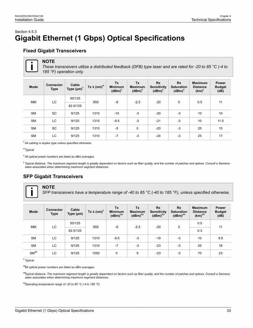
Gigabit Ethernet (1 Gbps) Optical SpecificationsFixed Gigabit Transceivers
NOTEThese transceivers utilize a distributed feedback (DFB) type laser and are rated for -20 to 85 °C (-4 to185 °F) operation only.
Mode ConnectorType
CableType (µm)v Tx λ (nm)w
TxMinimum
(dBm)x
TxMaximum
(dBm)x
RxSensitivity
(dBm)x
RxSaturation
(dBm)x
MaximumDistance
(km)y
PowerBudget
(dB)
50/125MM LC
62.5/125850 -9 -2.5 -20 0 0.5 11
SM SC 9/125 1310 -10 -3 -20 -3 10 10
SM LC 9/125 1310 -9.5 -3 -21 -3 10 11.5
SM SC 9/125 1310 -5 0 -20 -3 25 15
SM LC 9/125 1310 -7 -3 -24 -3 25 17
v All cabling is duplex type unless specified otherwise.
wTypical.
x All optical power numbers are listed as dBm averages.
y Typical distance. The maximum segment length is greatly dependent on factors such as fiber quality, and the number of patches and splices. Consult a Siemenssales associates when determining maximum segment distances.
SFP Gigabit Transceivers
NOTESFP transceivers have a temperature range of -40 to 85 °C (-40 to 185 °F), unless specified otherwise.
Mode ConnectorType
CableType (µm) Tx λ (nm)z
TxMinimum(dBm)aa
TxMaximum(dBm)aa
RxSensitivity
(dBm)aa
RxSaturation
(dBm)aa
MaximumDistance
(km)ab
PowerBudget
(dB)
50/125 0.5MM LC
62.5/125850 -9 -2.5 -20 0
0.311
SM LC 9/125 1310 -9.5 -3 -19 -3 10 9.5
SM LC 9/125 1310 -7 -3 -23 -3 25 16
SMac LC 9/125 1550 0 5 -23 -3 70 23
z Typical.
aaAll optical power numbers are listed as dBm averages.
abTypical distance. The maximum segment length is greatly dependent on factors such as fiber quality, and the number of patches and splices. Consult a Siemenssales associates when determining maximum segment distances.
acOperating temperature range of -20 to 85 °C (-4 to 185 °F).

Chapter 4Technical Specifications
RUGGEDCOM RSG2100Installation Guide
34 Operating Environment
GBIC Gigabit Transceivers
NOTEGBIC transceivers have a temperature range of -40 to 85 °C (-40 to 185 °F), unless specifiedotherwise.
Mode ConnectorType
CableType (µm)
Tx λ(nm)ad
TxMinimum(dBm)ae
TxMaximum(dBm)ae
RxSensitivity
(dBm)ae
RxSaturation
(dBm)ae
MaximumDistance
(km)af
PowerBudget
(dB)
SM SC 9/125 1310 -9.5 -3 -21 -3 10 11.5
SM SC 9/125 1310 -7 -3 -24 -3 25 17
SMag SC 9/125 1550 0 5 -23 -3 70 23
adTypical.
aeAll optical power numbers are listed as dBm averages.
afTypical distance. The maximum segment length is greatly dependent on factors such as fiber quality, and the number of patches and splices. Consult a Siemenssales associates when determining maximum segment distances.
agOperating temperature range of -20 to 85 °C (-4 to 185 °F).
Section 4.6
Operating EnvironmentParameter Range Comments
Ambient Operating Temperature -40 to 85 °C (-40 to 185 °F) Ambient Temperature as measured from a 30 cmradius surrounding the center of the enclosure.
Ambient Relative Humidity 5% to 95% Non-condensing
Ambient Storage Temperature -40 to 85 °C (-40 to 185 °F)
Section 4.7
Mechanical SpecificationsParameter Value
Dimensions Refer to Chapter 5, Dimension Drawings
Weight 5.2 kg (11.5 lbs)
Ingress Protection IP40 (1 mm or 0.04 in objects)
Enclosure 18 AWG Galvanized Steel

RUGGEDCOM RSG2100Installation Guide
Chapter 5Dimension Drawings
35
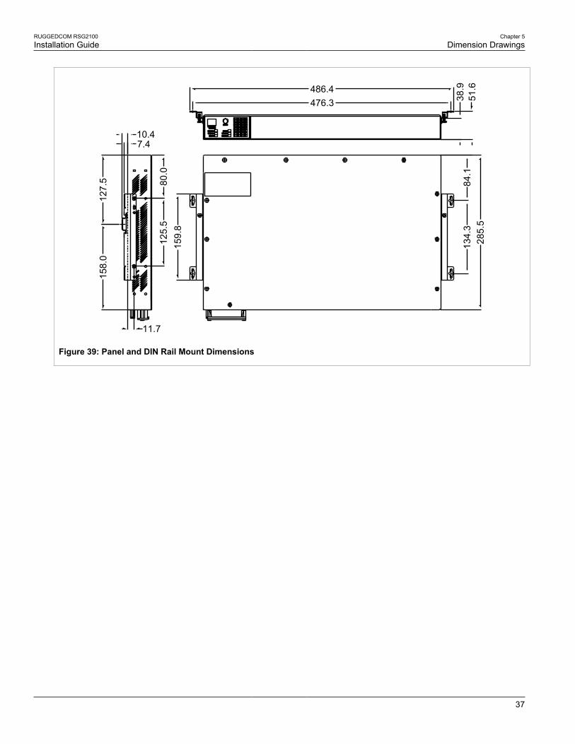
Dimension DrawingsNOTEAll dimensions are in millimeters, unless otherwise stated.
NOTEDimensional tolerances are in accordance with ISO 2768-mK, unless otherwise stated.
285.
24
303.
28
438.15
44.4
5 ±
0.8
Figure 37: Overall Dimensions

Chapter 5Dimension Drawings
RUGGEDCOM RSG2100Installation Guide
36
478.79
479.29
314.
70
308.
10
28.9
6
12.7
051
.05
25.4
0
11.6821.0832.77
6.35
31.7
54.57
6.35
Figure 38: Rack Mount Dimensions
RUGGEDCOM RSG2100Installation Guide
Chapter 5Dimension Drawings
37
MODE
STATUS
SPEEDDUPLEX
ALARM
POWER2POWER1
57600-N-8-1CONSOLE
1234
5678
1112 910
1314151617181920212223242526272829303132
11.7
159.
812
5.5
80.0
158.
012
7.5
10.47.4
486.4476.3 38
.951
.628
5.5
134.
384
.1
Figure 39: Panel and DIN Rail Mount Dimensions

RUGGEDCOM RSG2100Installation Guide
Chapter 5Dimension Drawings
38

RUGGEDCOM RSG2100Installation Guide
Chapter 6Certification
Standards Compliance 39
CertificationThe RUGGEDCOM RSG2100 device has been thoroughly tested to guarantee its conformance with recognizedstandards and has received approval from recognized regulatory agencies.
• Section 6.1, “Standards Compliance”
• Section 6.2, “Agency Approvals”
• Section 6.3, “EMI and Environmental Type Tests”
Section 6.1
Standards ComplianceThe RUGGEDCOM RSG2100 complies with the following standards:
• FCC ComplianceThis equipment has been tested and found to comply with the limits for a Class A digital device pursuantto Part 15 of the FCC Rules. These limits are designed to provide reasonable protection against harmfulinterference when the equipment is operated in a commercial environment.
This equipment generates, uses and can radiate radio frequency energy and, if not installed and used inaccordance with the instruction manual, may cause harmful interference to radio communications. Operationof this equipment in a residential area is likely to cause harmful interference in which case the user will berequired to correct the interference on his own expense.
• Industry Canada ComplianceCAN ICES-3 (A) / NMB-3 (A)
• Other▪ IEC 61000-6-2 (Generic Industrial)
▪ NEMA TS-2 (Traffic Control Equipment)
▪ IEEE 1613 (Electric Utility Substations)
▪ IEC 61850-3 (Electric Utility Substations)
▪ EN 50121-4 (Railway Equipment)
Section 6.2
Agency ApprovalsAgency Standards Comments
CSA CSA C22.2 No. 60950-1, UL 60950-1 Approved
CE EN 60950-1, EN 61000-6-2, EN60825-1, EN 55022 Class A, EN 50581
Approved
FCC FCC Part 15, Class A Approved

Chapter 6Certification
RUGGEDCOM RSG2100Installation Guide
40 EMI and Environmental Type Tests
Agency Standards Comments
FDA/CDRH 21 CFR Chapter I, Sub-chapter J Approved
ISO ISO9001:2008 Designed and manufactured using anISO9001:2008 certified quality program
Section 6.3
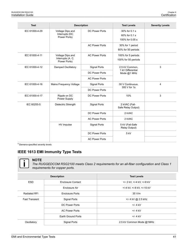
EMI and Environmental Type TestsThe RUGGEDCOM RSG2100 has passed the following EMI and environmental tests.
IEC 61850-3 EMI Type Tests
NOTE• In the case of an all fiber port configuration, this product meets all Class 2 requirements. Otherwise,
all Class 1 requirements are met for copper ports.
• If the unit contains copper ports, the IEC 1613 conformance is Class 1, during which disturbanceerrors may occur but recovery is automatic.
• If the unit contains all fiber ports, the IEC 1613 conformance is Class 2, during which no disturbanceerrors will occur.
Test Description Test Levels Severity Levels
Enclosure Contact +/- 8 kVIEC 61000-4-2 ESD
Enclosure Air +/- 15 kV
4
IEC 61000-4-3 Radiated RFI Enclosure Ports 20 V/m Notea
Signal Ports +/- 4 kV @ 2.5 kHz Notea
DC Power Ports
AC Power Ports
IEC 61000-4-4 Burst (Fast Transient)
Earth Ground Ports
+/- 4 kV 4
Signal Ports +/- 4 kV Line-to-Earth,+/- 2 kV Line-to-Line
4
DC Power Ports +/- 2 kV Line-to-Earth,+/- 1 kV Line-to-Line
3
IEC 61000-4-5 Surge
AC Power Ports +/- 4 kV Line-to-Earth,+/- 2 kV Line-to-Line
4
Signal Ports
DC Power Ports
AC Power Ports
IEC 61000-4-6 Induced (Conducted) RFI
Earth Ground Ports
10 V 3
40 A/m, continuous,1000 A/m for 1 s
NoteaIEC 61000-4-8 Magnetic Field Enclosure Ports
1000 A/m for 1 s 5
RUGGEDCOM RSG2100Installation Guide
Chapter 6Certification
EMI and Environmental Type Tests 41
Test Description Test Levels Severity Levels
DC Power Ports 30% for 0.1 s
60% for 0.1 s
100% for 0.05 s
IEC 61000-4-29 Voltage Dips andInterrupts (DCPower Ports)
AC Power Ports 30% for 1 period
60% for 50 periods
IEC 61000-4-11 Voltage Dips andInterrupts (A. C.
Power Ports)
AC Power Ports 100% for 5 periods
100% for 50 periods
Signal Ports
DC Power Ports
IEC 61000-4-12 Damped Oscillatory
AC Power Ports
2.5 kV Common,1 kV DifferentialMode @1 MHz
3
Signal PortsIEC 61000-4-16 Mains Frequency Voltage
DC Power Ports
30 V Continuous,300 V for 1s
4
IEC 61000-4-17 Ripple on DCPower Supply
DC Power Ports 10% 3
Signal Ports 2 kVAC (Fail-Safe Relay Output)
DC Power Ports 2 kVAC
Dielectric Strength
AC Power Ports 2 kVAC
Signal Ports 5 kV (Fail-SafeRelay Output)
DC Power Ports
IEC 60255-5
HV Impulse
AC Power Ports
5 kV
a Siemens-specified severity levels
IEEE 1613 EMI Immunity Type Tests
NOTEThe RUGGEDCOM RSG2100 meets Class 2 requirements for an all-fiber configuration and Class 1requirements for copper ports.
Description Test Levels
Enclosure Contact +/- 2 kV, +/-4 kV, +/-8 kVESD
Enclosure Air +/-4 kV, +/-8 kV, +/-15 kV
Radiated RFI Enclosure Ports 35 V/m
Signal Ports +/- 4 kV @ 2.5 kHz
DC Power Ports +/- 4 kV
AC Power Ports +/- 4 kV
Fast Transient
Earth Ground Ports +/- 4 kV
Oscillatory Signal Ports 2.5 kV Common Mode @1MHz

Chapter 6Certification
RUGGEDCOM RSG2100Installation Guide
42 EMI and Environmental Type Tests
Description Test Levels
DC Power Ports 2.5 kV common, 1 kV differential mode @ 1 MHz
AC Power Ports 2.5 kV common, 1 kV differential mode @ 1 MHz
Signal Ports 5 kV (Fail-Safe Relay Output)
DC Power Ports 5 kV
HV Impulse
AC Power Ports 5 kV
Signal Ports 2 kVAC
DC Power Ports 2 kVDC
Dielectric Strength
AC Power Ports 2 kVAC
Damped OscillatoryMagnetic Field
Enclosure Ports 100 A/m Peak
Environmental Type TestsTest Description Test Levels
IEC 60068-2-1 Cold Temperature Test Ad -40 °C (-40 °F), 16 Hours
IEC 60068-2-2 Dry Heat Test Bd 85 °C (185 °F), 16 Hours
IEC 60068-2-30 Humidity (Damp Heat, Cyclic) Test Db 95% (non-condensing),55 °C (131 °F), 6 cycles
IEC 60068-21-1 Vibration 2g @ 10-50 Hz
IEC 60068-21-2 Shock 30 g @ 11 ms