Embed Size (px)
Citation preview
RUGGEDCOM WIN5237
Installation Guide
01/2018RC1140-EN-05
Preface
Introduction 1Installing the SubscriberStation 2
Technical Specifications 3
Dimension Drawings 4
Certification 5
RUGGEDCOM WIN5237Installation Guide
ii
Copyright © 2018 Siemens Canada LtdAll rights reserved. Dissemination or reproduction of this document, or evaluation and communication of its contents, is not authorizedexcept where expressly permitted. Violations are liable for damages. All rights reserved, particularly for the purposes of patent application ortrademark registration.This document contains proprietary information, which is protected by copyright. All rights are reserved. No part of this document may bephotocopied, reproduced or translated to another language without the prior written consent of Siemens Canada Ltd.
Disclaimer Of LiabilitySiemens has verified the contents of this document against the hardware and/or software described. However, deviations between the productand the documentation may exist.Siemens shall not be liable for any errors or omissions contained herein or for consequential damages in connection with the furnishing,performance, or use of this material.The information given in this document is reviewed regularly and any necessary corrections will be included in subsequent editions. Weappreciate any suggested improvements. We reserve the right to make technical improvements without notice.
Registered TrademarksRUGGEDCOM™ and ROS™ are trademarks of Siemens Canada Ltd.Other designations in this manual might be trademarks whose use by third parties for their own purposes would infringe the rights of theowner.
Security InformationSiemens provides products and solutions with industrial security functions that support the secure operation of plants, machines, equipmentand/or networks. They are important components in a holistic industrial security concept. With this in mind, Siemens' products and solutionsundergo continuous development. Siemens recommends strongly that you regularly check for product updates.For the secure operation of Siemens products and solutions, it is necessary to take suitable preventive action (e.g. cell protection concept) andintegrate each component into a holistic, state-of-the-art industrial security concept. Third-party products that may be in use should also beconsidered. For more information about industrial security, visit http://www.siemens.com/industrialsecurity.To stay informed about product updates as they occur, sign up for a product-specific newsletter. For more information, visit http://support.automation.siemens.com.
WarrantySiemens warrants this product for a period of five (5) years from the date of purchase, conditional upon the return to factory for maintenanceduring the warranty term. This product contains no user-serviceable parts. Attempted service by unauthorized personnel shall render allwarranties null and void. The warranties set forth in this article are exclusive and are in lieu of all other warranties, performance guaranteesand conditions whether written or oral, statutory, express or implied (including all warranties and conditions of merchantability and fitness fora particular purpose, and all warranties and conditions arising from course of dealing or usage or trade). Correction of nonconformities in themanner and for the period of time provided above shall constitute the Seller’s sole liability and the Customer’s exclusive remedy for defectiveor nonconforming goods or services whether claims of the Customer are based in contract (including fundamental breach), in tort (includingnegligence and strict liability) or otherwise.For warranty details, visit https://www.siemens.com/ruggedcom or contact a Siemens customer service representative.
Contacting SiemensAddressSiemens Canada LtdIndustry Sector300 Applewood CrescentConcord, OntarioCanada, L4K 5C7
TelephoneToll-free: 1 888 264 0006Tel: +1 905 856 5288Fax: +1 905 856 1995
[email protected]://www.siemens.com/ruggedcom
RUGGEDCOM WIN5237Installation Guide
Table of Contents
iii
Table of ContentsPreface ............................................................................................................. v
Alerts .................................................................................................................................................. vRelated Documents ............................................................................................................................. viTraining .............................................................................................................................................. viCustomer Support ............................................................................................................................... vi
Chapter 1Introduction ..................................................................................................... 1
1.1 Feature Highlights ........................................................................................................................ 21.2 Description ................................................................................................................................... 2
Chapter 2Installing the Subscriber Station ....................................................................... 5
2.1 General Procedure ........................................................................................................................ 62.2 Unpacking the Subscriber Station ................................................................................................... 72.3 Required Tools and Materials ......................................................................................................... 72.4 Site Preparation and Precautions .................................................................................................... 82.5 Installing the Subscriber Station in Hazardous Locations .................................................................. 92.6 Mounting the Subscriber Station .................................................................................................. 10
2.6.1 Mounting the Subscriber Station to a Wall or Tower ........................................................... 112.6.2 Mounting the Subscriber Station to a Pole ......................................................................... 12
2.7 Grounding the Subscriber Station ................................................................................................. 152.8 Connecting Power and Data ........................................................................................................ 15
2.8.1 Connecting the RUGGEDCOM WIN1010 ............................................................................. 162.8.2 Connecting to a RUGGEDCOM RP100 or RP110 ................................................................... 172.8.3 Assembling the PoE Connector .......................................................................................... 172.8.4 Installing the Hazardous Location Kit ................................................................................. 21
2.9 Weatherproofing the Subscriber Station ....................................................................................... 222.9.1 Weatherproofing a Cable .................................................................................................. 232.9.2 Applying Cold Shrink Tubing ............................................................................................. 232.9.3 Applying Self-Amalgamating Tape ..................................................................................... 24
2.10 Configuring the Subscriber Station ............................................................................................. 24

Table of Contents
RUGGEDCOM WIN5237Installation Guide
iv
Chapter 3Technical Specifications .................................................................................. 25
3.1 Power Consumption .................................................................................................................... 253.2 Radio and Modem Specifications .................................................................................................. 253.3 Operating Environment ............................................................................................................... 263.4 Mechanical Specifications ............................................................................................................ 263.5 IDU to ODU Cable Specifications .................................................................................................. 26
Chapter 4Dimension Drawings ....................................................................................... 29
Chapter 5Certification .................................................................................................... 31
5.1 Approvals ................................................................................................................................... 315.1.1 MET Laboratories ............................................................................................................. 315.1.2 CSA ................................................................................................................................. 325.1.3 European Union (EU) ....................................................................................................... 335.1.4 TÜV Rheinland ................................................................................................................. 335.1.5 ISED ................................................................................................................................ 335.1.6 FCC ................................................................................................................................. 335.1.7 IEEE ................................................................................................................................ 34
5.2 Environmental Type Tests ............................................................................................................ 34
RUGGEDCOM WIN5237Installation Guide
Preface
Alerts v
PrefaceThis guide describes the RUGGEDCOM WIN5237. It describes the major features of the subscriber station,installation, commissioning and important technical specifications.It is intended for use by subscriber station installers and operators, and assumes readers have a workingknowledge of WiMAX technologies and procedures. While some safety precautions are reviewed here, it isassumed that installers are trained in safe installation practices. Users unfamiliar with safe installation procedures,WiMAX technologies, and service procedures should not rely on this manual for comprehensive guidance.
CONTENTS• “Alerts”• “Related Documents”• “Training”• “Customer Support”
AlertsThe following types of alerts are used when necessary to highlight important information.
DANGER!DANGER alerts describe imminently hazardous situations that, if not avoided, will result in death orserious injury.
WARNING!WARNING alerts describe hazardous situations that, if not avoided, may result in serious injury and/orequipment damage.
CAUTION!CAUTION alerts describe hazardous situations that, if not avoided, may result in equipment damage.
IMPORTANT!IMPORTANT alerts provide important information that should be known before performing a procedureor step, or using a feature.
NOTENOTE alerts provide additional information, such as facts, tips and details.

Preface
RUGGEDCOM WIN5237Installation Guide
vi Related Documents
Related DocumentsOther documents that may be of interest include:• RUGGEDCOM SS User Guide• RUGGEDCOM RP100 Installation Guide• RUGGEDCOM RP110 Installation Guide
TrainingSiemens offers a wide range of educational services ranging from in-house training of standard courses onnetworking, Ethernet switches and routers, to on-site customized courses tailored to the customer's needs,experience and application.Siemens' Educational Services team thrives on providing our customers with the essential practical skills to makesure users have the right knowledge and expertise to understand the various technologies associated with criticalcommunications network infrastructure technologies.Siemens' unique mix of IT/Telecommunications expertise combined with domain knowledge in the utility,transportation and industrial markets, allows Siemens to provide training specific to the customer's application.For more information about training services and course availability, visit https://www.siemens.com/ruggedcom orcontact a Siemens Sales representative.
Customer SupportCustomer support is available 24 hours, 7 days a week for all Siemens customers. For technical support or generalinformation, contact Siemens Customer Support through any of the following methods:
OnlineVisit http://www.siemens.com/automation/support-request to submit a Support Request (SR) or checkon the status of an existing SR.
TelephoneCall a local hotline center to submit a Support Request (SR). To locate a local hotline center, visit http://www.automation.siemens.com/mcms/aspa-db/en/automation-technology/Pages/default.aspx.
Mobile AppInstall the Industry Online Support app by Siemens AG on any Android, Apple iOS or Windows mobiledevice and be able to:• Access Siemens' extensive library of support documentation, including FAQs and manuals• Submit SRs or check on the status of an existing SR• Contact a local Siemens representative from Sales, Technical Support, Training, etc.• Ask questions or share knowledge with fellow Siemens customers and the support community

RUGGEDCOM WIN5237Installation Guide
Chapter 1Introduction
1
IntroductionThe RUGGEDCOM WIN5237 subscriber station (also referred to as Customer Premises Equipment) is part of theRUGGEDCOM WIN family, a line of mobile WiMAX broadband wireless access systems based on the IEEE 802.16emobile WiMAX standard.The RUGGEDCOM WIN5237 is a high-performance, self-learning subscriber. It automatically detects the basestation on the best signal available, allowing for plug-and-play installation and maintenance free operation. Theautomatic switching and monitoring features guarantee on-going operation in changing conditions, which resultsin low maintenance and considerable operating expense savings.The subscriber station is compliant with IEEE 802.16e standards to effectively meet the unique requirements ofthe wireless Metropolitan Area Network (MAN) environment and to deliver broadband access services to a widerange of customers. Specifically designed for point-to-multipoint broadband wireless access applications, thesubscriber station provides efficient use of the wireless spectrum, supporting a range of user environments.The subscriber station also complies with the IEEE 802.16-2005 standard for the deployment of point-to-multipoint (PMP) and point-to-point (PTP) network architectures.The subscriber station is a WiMAX Forum IEEE 802.16e Wave 2 (MIMO) certified subscriber. Each subscriberregisters and establishes a bi-directional data link with the base station.Primary benefits offered by the RUGGEDCOM WIN5237 include:• Non-Line-of-Sight (NLOS) Propogation
Provides excellent performance in NLOS conditions. Mitigates multi-path and deep fading, providing extendedrange and easy installation.
• Automatic Transmit Power Control (ATPC)ATPC allows for optimal network deployment, tight frequency reuse, and interference avoidance.
• Power over Ethernet (PoE)Supports single cable PoE.
• Wide Frequency BandProvides support for deployments around the world.
CONTENTS• Section 1.1, “Feature Highlights”• Section 1.2, “Description”

Chapter 1Introduction
RUGGEDCOM WIN5237Installation Guide
2 Feature Highlights
Section 1.1
Feature Highlights
Long RangeThe subscriber station has multiple built-in receivers to improve range and Non-Line-of-Sight (NLoS) performance.The system has the ability to leverage sub-channelization technology to balance links with high-power basestations.
Robust DesignThe subscriber station is designed for mission critical applications in harsh environments with very high MeanTime Before Failure.
Quality of ServiceThe subscriber station gives the user the ability to separate traffic types over the air, and guarantee latency,minimum bandwidth and jitter according to application needs.
Power Supply OptionsWhen combined with the injector series (RUGGEDCOM RP100 or RP110), the subscriber station offers theindustry’s leading power supply options with 12 VDC, 24 VDC, 48 VDC, and 88–300 VDC or 85–264 VAC availablefor a variety of industrial applications.
FlexibilityThe subscriber station supports both IP convergence sublayer for wireless Internet service providers or EthernetConvergence Sublayer, ideal for mission critical private networks.
Section 1.2
DescriptionThe RUGGEDCOM WIN5237 features various ports, controls and indicator LEDs on the bottom panel forconnecting, configuring and troubleshooting the subscriber station.
RUGGEDCOM WIN5237Installation Guide
Chapter 1Introduction
Description 3
RSSI
W.LINK PWR2
1
3
ETH/PWR
RSSI
W.LINK PWR
4
5
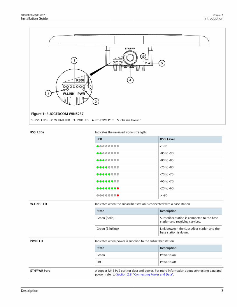
Figure 1: RUGGEDCOM WIN5237
1. RSSI LEDs 2. W.LINK LED 3. PWR LED 4. ETH/PWR Port 5. Chassis Ground
RSSI LEDs Indicates the received signal strength.
LED RSSI Level
< -90
-85 to -90
-80 to -85
-75 to -80
-70 to -75
-65 to -70
-20 to -60
> -20
W.LINK LED Indicates when the subscriber station is connected with a base station.
State Description
Green (Solid) Subscriber station is connected to the basestation and receiving services.
Green (Blinking) Link between the subscriber station and thebase station is down.
PWR LED Indicates when power is supplied to the subscriber station.
State Description
Green Power is on.
Off Power is off.
ETH/PWR Port A copper RJ45 PoE port for data and power. For more information about connecting data andpower, refer to Section 2.8, “Connecting Power and Data”.

Chapter 1Introduction
RUGGEDCOM WIN5237Installation Guide
4 Description
Chassis Ground Connection Protects the subscriber station from power surges and accumulated static electricity. Forinformation about grounding the subscriber station, refer to Section 2.7, “Grounding theSubscriber Station”.
RUGGEDCOM WIN5237Installation Guide
Chapter 2Installing the Subscriber Station
5
Installing the Subscriber StationThis chapter describes how to install the subscriber station, including mounting the subscriber station, connectingpower, connecting the antenna, and connecting the subscriber station to the network.
DANGER!Electrocution hazard – risk of serious personal injury and/or damage to equipment. Before performingany maintenance tasks, make sure all power to the subscriber station has been disconnected and waitapproximately two minutes for any remaining energy to dissipate.
DANGER!Electrocution hazard – risk of death or serious injury. When the subscriber station is installed in anoutdoor location, all indoor components (e.g. Ethernet and power supply) should be connectedthrough a lightning protector.Lightning protection protects people and equipment located indoors from lightning that may strikethe subscriber station or its outdoor cables. Therefore, install the lightning protector indoors, asclose as possible to the point where the cables enter the building. The lightning protector can also beinstalled outdoors as long as the cables that lead indoors are well protected from lightning betweenthe protector and the building entrance.
WARNING!Safety hazard – risk of serious personal injury and/or damage to equipment. Installing theRUGGEDCOM WIN5237 can pose a serious safety hazard. Be sure to take precautions to avoid thefollowing:• Exposure to high voltage lines during installation• Falling when working at heights or with ladders• Injuries from dropping tools• Contact with AC wiring (power system connection)
IMPORTANT!Only certified personnel should be permitted to install equipment.
IMPORTANT!This product contains no user-serviceable parts. Attempted service by unauthorized personnel shallrender all warranties null and void.Changes or modifications not expressly approved by Siemens Canada Ltd could invalidatespecifications, test results, and agency approvals, and void the user's authority to operate theequipment.

Chapter 2Installing the Subscriber Station
RUGGEDCOM WIN5237Installation Guide
6 General Procedure
IMPORTANT!This product should be installed in a restricted access location where access can only be gained byauthorized personnel who have been informed of the restrictions and any precautions that must betaken. Access must only be possible through the use of a tool, lock and key, or other means of security,and controlled by the authority responsible for the location.
IMPORTANT!Install equipment in accordance with the electrical code relevant to the country of installation, such as:• the National Electrical Code (NEC), ANSI/NFPA 70• the Canadian Electrical Code (CEC), Part 1, CSA C22.1• the National Electrical Safety Code IEEE C2 (when applicable)Unless marked or otherwise identified, the Standard for the Protection of Electronic Computer/DataProcessing Equipment, ANSI/NFPA 75, also applies.
IMPORTANT!Outdoor exposed communication lines longer than 40 m (140 ft) must be considered as TNV-1 circuits.The installer must make sure the power supply and network ports are designed for full compliance withthe standards for TNV-1 telecommunication networks.
CONTENTS• Section 2.1, “General Procedure”• Section 2.2, “Unpacking the Subscriber Station”• Section 2.3, “Required Tools and Materials”• Section 2.4, “Site Preparation and Precautions”• Section 2.5, “Installing the Subscriber Station in Hazardous Locations”• Section 2.6, “Mounting the Subscriber Station”• Section 2.7, “Grounding the Subscriber Station”• Section 2.8, “Connecting Power and Data”• Section 2.9, “Weatherproofing the Subscriber Station”• Section 2.10, “Configuring the Subscriber Station”
Section 2.1
General ProcedureThe general procedure for installing the subscriber station is as follows:
IMPORTANT!Before installing the subscriber station in a Class I, Division 2 hazardous location, make sure to reviewthe conditions for safe use. For more information, refer to Section 2.5, “Installing the Subscriber Stationin Hazardous Locations”.
1. Review the relevant certification information for any regulatory requirements. For more information, refer toSection 5.1, “Approvals”.
RUGGEDCOM WIN5237Installation Guide
Chapter 2Installing the Subscriber Station
Unpacking the Subscriber Station 7
2. Unpack and inspect the subscriber station components. For more information, refer to Section 2.2,“Unpacking the Subscriber Station”.
3. Mount the subscriber station to a pole, wall or tower. For more information, refer to Section 2.6, “Mountingthe Subscriber Station”.
4. Assemble the PoE cable. For more information, refer to Section 2.8.3, “Assembling the PoE Connector”.5. Make sure the subscriber station is grounded. For more information, refer to Section 2.7, “Grounding the
Subscriber Station”.6. Connect the subscriber station to a power source and the network. For more information, refer to Section 2.8,
“Connecting Power and Data”.7. Seal all cable connections. For more information, refer to Section 2.9, “Weatherproofing the Subscriber
Station”.8. Configure the subscriber station. For more information, refer to Section 2.10, “Configuring the Subscriber
Station”.
Section 2.2
Unpacking the Subscriber StationThe following items are included in the RUGGEDCOM WIN5237 package:• RUGGEDCOM WIN5237 Subscriber Station• RUGGEDCOM WIN1010 AC Power Injector• 2 × Radio Frequency (RF) antenna cables, 5 m (16.4 ft) long• Pole/wall/tower mounting kit• RJ45 PoE connector kitWhen unpacking the subscriber station, do the following:1. Inspect the package for damage before opening it.2. Visually inspect each item in the package for any physical damage.3. Verify all items are included.If any item is missing or damaged, contact Siemens for assistance.
Section 2.3
Required Tools and MaterialsThe following tools and materials are required to install the RUGGEDCOM WIN5237:Kits
• Class I, Division 2 Kit (P/N MKIT0090) – For hazardouslocations only
Tools
• Wrench or socket set• Phillips screwdriver• Drill with an 8 mm (5/16 in) drill bit
Greases
• Marine grease (for marine applications only)
Tapes
• POE cold shrink (maximum 49.2 mm or 1.9 in innerdiameter before shrinking) or self-amalgamating tape
• UV-resistant vinyl tape• Electrical insulation putty
Chapter 2Installing the Subscriber Station
RUGGEDCOM WIN5237Installation Guide
8 Site Preparation and Precautions
• Wall anchors (if necessary)
Sprays
• Cleaner and de-greaser• SCC3 conformal coating• Corrosion protection
Mounting Hardware (Wall/Tower Only)
• Four 1/4" × 1/2" HEX chipboard screws• Four 1/4" flat washers• Four 1/4" spring washers
Section 2.4
Site Preparation and PrecautionsBefore installing the subscriber station and or antenna(s), it is important to plan the the complete installation andmake sure the appropriate safe guards are in place.
Site SelectionConsider the following recommendations when selecting an appropriate site for the subscriber station andantenna(s):• Mount the antenna(s) at the highest point possible. Reception will increase according to the height of the
antenna(s).• Mount the antenna(s) in a place with as few obstructions as possible between the antenna(s) and the planned
service area.• To avoid interference, mount the antenna(s) and subscriber station as far as possible from other antenna(s) and
subscriber stations.• Keep the cable from the subscriber station to the antenna(s) as short as possible and mount the antenna(s) as
close as possible to the subscriber station. Using a cable longer than 2 m (6.6 ft) will result in greater loss andmore interference, as the cable will act as an antenna itself.
• Do not point the antenna(s) directly at populated areas.• Locate the antenna(s) at least 3.6 m (11.8 ft) from people and public areas.• Make sure the antenna(s) and subscriber station are easily accessible for maintenance purposes.• Conduct a site survey to best position the subscriber station and antenna(s) in relation to other subscriber
stations, antennas and base stations in the area. The site survey should also take into consideration the overallsafety of the selected site
Site SurveyMost wireless networks include many subscriber/base stations installed in various locations in an overlappingradio-cell pattern. It is important to position each subscriber station in an optimal location considering theassignment of its radio channels. Therefore, a site survey becomes an essential first step before physicallydeploying the subscriber station.The site survey should include details important to the planning of the subscriber station deployment in eachspecific site, including potential mounting points for the subscriber station and antennas, as well as the routingoptions for data, power and antenna cables.For safety, always consult with the local power utility as well. It is important to select a site that not only offersmaximum coverage, but is also safe for installers to work in.
RUGGEDCOM WIN5237Installation Guide
Chapter 2Installing the Subscriber Station
Installing the Subscriber Station in Hazardous Locations 9
Safety PrecautionsWhen installing the subscriber station or an antenna, make sure to adhere to the following safety precautions:• Always install the subscriber station with the help of a partner.• Always use the most appropriate mounting method for the site and the equipment being installed. For
assistance, contact a Siemens representative.• Always assume an overhead line can cause serious injury or death. Note that electric power lines and phone
lines look alike.• Always wear the appropriate Personal Protective Equipment (PPE) for the task, including but not limited to
rubber boots, rubber gloves, hard hat, harness and lanyard, etc.• Always use a ladder made of a non-conductive material, such as wood or fiberglass. Do not use a metal ladder.• Always work under favorable conditions. Do not work on wet or windy days.• If the subscriber station or antenna begins to drop, step away immediately and allow it to fall. The subscriber
station, cables, metal guy wires and pole (in the case of pole mount installations) are all excellent conductors.Any contact between these components and an electrical power line will complete an electrical path throughthe subscriber station/antenna and the installer.
• If any part of the subscriber station or an antenna comes in contact with an electrical power line, contact thelocal power utility. Do not attempt to touch or remove the component.
Section 2.5
Installing the Subscriber Station in HazardousLocations
The RUGGEDCOM WIN5237 is designed to comply with the safety standards for Class I, Division 2, Zone 2hazardous locations where concentrations of flammable gases, vapors or liquids may be present, as opposed tonormal operating environments.
Special Conditions for Safe UseInstallation and use of the subscriber station in a hazardous location must meet the following special conditionsfor safe use:• Substitution of components may impair suitability for Class I, Division 2• Do not disconnect equipment unless power has been switched off or the area is known to be non-hazardous• Use only Lambda DPP50-48 Power Supply in conjunction with the unit
NOTEFor further details of the subscriber station's compliance with Class I, Division 2, Zone 2 standards, referto Section 5.1, “Approvals”.
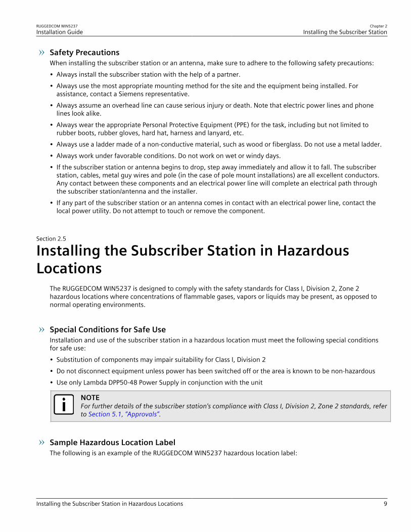
Sample Hazardous Location LabelThe following is an example of the RUGGEDCOM WIN5237 hazardous location label:

Chapter 2Installing the Subscriber Station
RUGGEDCOM WIN5237Installation Guide
10 Mounting the Subscriber Station
P/N: WiN52XX-Y-ZZZCPE xxxx-xxxx MHz
S/N:XXXXWWYYXX
WARNING - EXPLOSION HAZARDDO NOT SEPARATE WHILE CIRCUIT IS LIVEUNLESS AREA IS KNOWN TO BE SAFEAVERTISSEMENT - RISQUE D'EXPLOSIONNE PAS DÉBRANCHER TANT QUE LE CIRCUIT EST SOUS TENSION,À MOINS QU'IL NES S'AGISSE D'UN EMPLACEMENT NON DANGEREUX
I I 3 G nA I IC T4 X
Rating: DC 48V, 1AClass I Division 2 Groups A, B, C, DT4
Figure 2: Compliance Label (Example)
Section 2.6
Mounting the Subscriber StationThe RUGGEDCOM WIN5237 is designed for maximum mounting and display flexibility. It can be secured to abracket and then mounted to a pole, wall or tower.
NOTEFor detailed dimensions of the subscriber station, refer to Chapter 4, Dimension Drawings.
When choosing the mounting location for the unit, consider the available mounting structures and antennaclearance.
Site SurveyMost wireless networks include many subscriber/base stations installed in various locations in an overlappingradio-cell pattern. It is important to position each subscriber station in an optimal location considering theassignment of its radio channels. Therefore, a site survey becomes an essential first step before physicallydeploying the subscriber station.The site survey should include details important to the planning of the subscriber station deployment in eachspecific site, including potential mounting points for the subscriber station and antennas, as well as the routingoptions for data, power and antenna cables.
Recommended Site RequirementsIt is highly recommended the subscriber station be mounted with as few obstructions as possible between itselfand the base station. The subscriber station should be pointed in the direction of the designated server basestation. When choosing the ideal location, it is also important to take into consideration the overall area topology.
CONTENTS• Section 2.6.1, “Mounting the Subscriber Station to a Wall or Tower”• Section 2.6.2, “Mounting the Subscriber Station to a Pole”
RUGGEDCOM WIN5237Installation Guide
Chapter 2Installing the Subscriber Station
Mounting the Subscriber Station to a Wall or Tower 11
Section 2.6.1
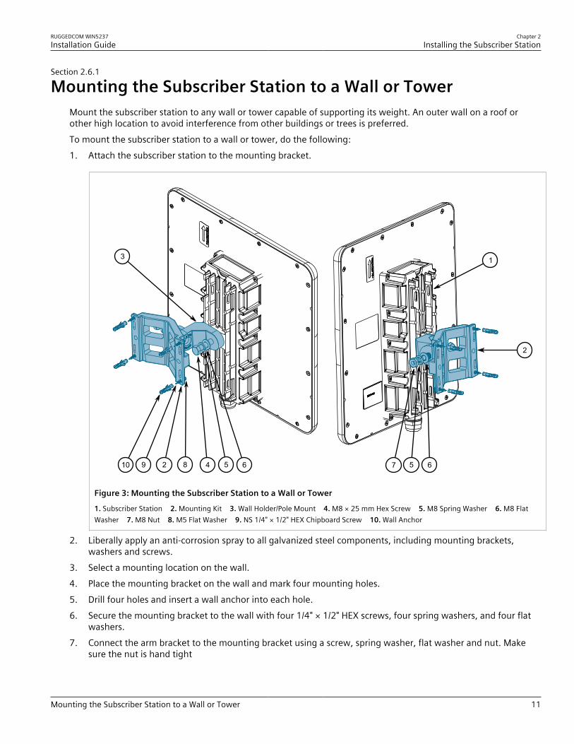
Mounting the Subscriber Station to a Wall or TowerMount the subscriber station to any wall or tower capable of supporting its weight. An outer wall on a roof orother high location to avoid interference from other buildings or trees is preferred.To mount the subscriber station to a wall or tower, do the following:1. Attach the subscriber station to the mounting bracket.
657
13
5 6482910
2
Figure 3: Mounting the Subscriber Station to a Wall or Tower
1. Subscriber Station 2. Mounting Kit 3. Wall Holder/Pole Mount 4. M8 × 25 mm Hex Screw 5. M8 Spring Washer 6. M8 FlatWasher 7. M8 Nut 8. M5 Flat Washer 9. NS 1/4" × 1/2" HEX Chipboard Screw 10. Wall Anchor
2. Liberally apply an anti-corrosion spray to all galvanized steel components, including mounting brackets,washers and screws.
3. Select a mounting location on the wall.4. Place the mounting bracket on the wall and mark four mounting holes.5. Drill four holes and insert a wall anchor into each hole.6. Secure the mounting bracket to the wall with four 1/4" × 1/2" HEX screws, four spring washers, and four flat
washers.7. Connect the arm bracket to the mounting bracket using a screw, spring washer, flat washer and nut. Make
sure the nut is hand tight

Chapter 2Installing the Subscriber Station
RUGGEDCOM WIN5237Installation Guide
12 Mounting the Subscriber Station to a Pole
8. Connect the subscriber station to the arm bracket using a screw, spring washer, flat washer and nut. Makesure the nut is hand tight.
9. Point the front face of the subscriber station in the general direction of the designated base station.10. Make sure the PWR LED on the subscriber station is on.11. Position the subscriber station until the maximum RSSI link quality reading is achieved. A single RSSI LED
indicates the subscriber station is at minimum synchronized with the base station. For information about theRSSI LED indicators, refer to Section 1.2, “Description”.If the subscriber station is not synchronized with the base station, make sure the subscriber station is properlyconfigured. For more information, refer to the RUGGEDCOM WIN User Guide for the RUGGEDCOM WIN5237.If the expected link quality still cannot be achieved, try to improve the reception quality by placing thesubscriber station at a higher point or in an alternate location.
12. Make sure the subscriber station is properly grounded according to local standards. For more information,refer to Section 2.7, “Grounding the Subscriber Station”.
13. Tighten the screws connecting the arm bracket to the subscriber station and mounting bracket. Make sure thescrews are torqued to 24 N·m (17.7 ft. lb.).
Section 2.6.2
Mounting the Subscriber Station to a PoleThe subscriber station can be attached to any pipe or pole with a diameter of 44.5 to 254 mm (1.75 to 10 in).To mount the subscriber station to a pole, do the following:1. Attach the subscriber station to the mounting bracket.

RUGGEDCOM WIN5237Installation Guide
Chapter 2Installing the Subscriber Station
Mounting the Subscriber Station to a Pole 13
2
68
3
65 73
4
1
967
Figure 4: Mounting the Subscriber Station to a Large Pole
1. Subscriber Station 2. Pole 3. Clamping Bracket 4. Mounting Bracket 5. M8-25 Hex Screw 6. M8 Spring Washer 7. M8 FlatWasher 8. M8 Nut 9. M8-70 Hex Screw
Chapter 2Installing the Subscriber Station
RUGGEDCOM WIN5237Installation Guide
14 Mounting the Subscriber Station to a Pole
2
9
6
3
776865 73
4
1
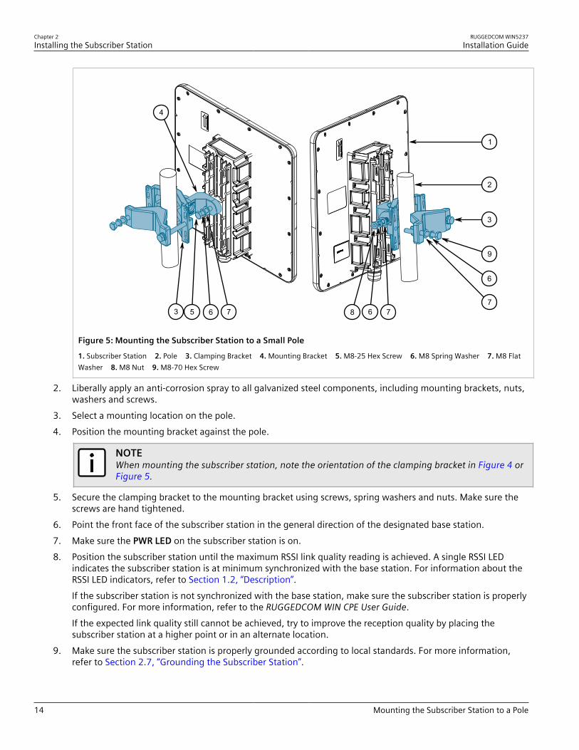
Figure 5: Mounting the Subscriber Station to a Small Pole
1. Subscriber Station 2. Pole 3. Clamping Bracket 4. Mounting Bracket 5. M8-25 Hex Screw 6. M8 Spring Washer 7. M8 FlatWasher 8. M8 Nut 9. M8-70 Hex Screw
2. Liberally apply an anti-corrosion spray to all galvanized steel components, including mounting brackets, nuts,washers and screws.
3. Select a mounting location on the pole.4. Position the mounting bracket against the pole.
NOTEWhen mounting the subscriber station, note the orientation of the clamping bracket in Figure 4 orFigure 5.
5. Secure the clamping bracket to the mounting bracket using screws, spring washers and nuts. Make sure thescrews are hand tightened.
6. Point the front face of the subscriber station in the general direction of the designated base station.7. Make sure the PWR LED on the subscriber station is on.8. Position the subscriber station until the maximum RSSI link quality reading is achieved. A single RSSI LED
indicates the subscriber station is at minimum synchronized with the base station. For information about theRSSI LED indicators, refer to Section 1.2, “Description”.If the subscriber station is not synchronized with the base station, make sure the subscriber station is properlyconfigured. For more information, refer to the RUGGEDCOM WIN CPE User Guide.If the expected link quality still cannot be achieved, try to improve the reception quality by placing thesubscriber station at a higher point or in an alternate location.
9. Make sure the subscriber station is properly grounded according to local standards. For more information,refer to Section 2.7, “Grounding the Subscriber Station”.
RUGGEDCOM WIN5237Installation Guide
Chapter 2Installing the Subscriber Station
Grounding the Subscriber Station 15
10. Tighten the screws connecting the clamping bracket to the mounting bracket. Make sure the screws aretorqued to 14 N·m (10 lbf-ft).
Section 2.7
Grounding the Subscriber StationWhen connecting the ground cable to the subscriber station, make sure to use a 10 AWG grounding cable andtorque the screw to 15 N·m (11 ft. lb.).
DANGER!Electrocution hazard – risk of death or serious injury. The system must be properly grounded to protectagainst power surges and accumulated static electricity. It is the installer’s responsibility to install thisbase station in accordance with the local electrical codes.
Section 2.8
Connecting Power and DataThe subscriber station can be connected to one of the following Power-over-Ethernet (PoE) injectors in non-hazardous locations:• RUGGEDCOM WIN1010 (included)• RUGGEDCOM RP100• RUGGEDCOM RP110
CAUTION!Crushing hazard – risk of damage to cables. Route all power supply cables so that people cannot walkon them or place objects on or against them.
IMPORTANT!This subscriber station is a non-standard PoE device. Do not attempt to use a third-party PoE injector.Other types of connections or application of the subscriber station not described in this document arestrictly prohibited and may void the warranty.
CONTENTS• Section 2.8.1, “Connecting the RUGGEDCOM WIN1010”• Section 2.8.2, “Connecting to a RUGGEDCOM RP100 or RP110 ”• Section 2.8.3, “Assembling the PoE Connector”• Section 2.8.4, “Installing the Hazardous Location Kit”
Chapter 2Installing the Subscriber Station
RUGGEDCOM WIN5237Installation Guide
16 Connecting the RUGGEDCOM WIN1010
Section 2.8.1
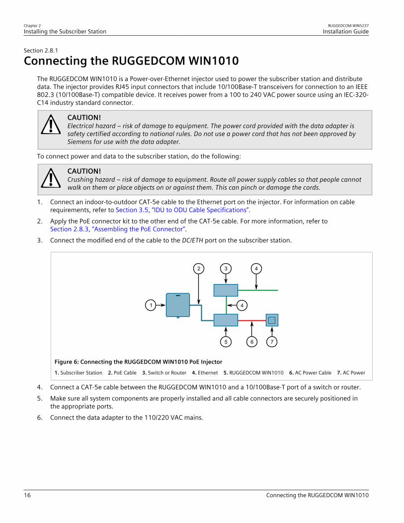
Connecting the RUGGEDCOM WIN1010The RUGGEDCOM WIN1010 is a Power-over-Ethernet injector used to power the subscriber station and distributedata. The injector provides RJ45 input connectors that include 10/100Base-T transceivers for connection to an IEEE802.3 (10/100Base-T) compatible device. It receives power from a 100 to 240 VAC power source using an IEC-320-C14 industry standard connector.
CAUTION!Electrical hazard – risk of damage to equipment. The power cord provided with the data adapter issafety certified according to national rules. Do not use a power cord that has not been approved bySiemens for use with the data adapter.
To connect power and data to the subscriber station, do the following:
CAUTION!Crushing hazard – risk of damage to equipment. Route all power supply cables so that people cannotwalk on them or place objects on or against them. This can pinch or damage the cords.
1. Connect an indoor-to-outdoor CAT-5e cable to the Ethernet port on the injector. For information on cablerequirements, refer to Section 3.5, “IDU to ODU Cable Specifications”.
2. Apply the PoE connector kit to the other end of the CAT-5e cable. For more information, refer toSection 2.8.3, “Assembling the PoE Connector”.
3. Connect the modified end of the cable to the DC/ETH port on the subscriber station.
1
3 4
4
2
765
Figure 6: Connecting the RUGGEDCOM WIN1010 PoE Injector
1. Subscriber Station 2. PoE Cable 3. Switch or Router 4. Ethernet 5. RUGGEDCOM WIN1010 6. AC Power Cable 7. AC Power
4. Connect a CAT-5e cable between the RUGGEDCOM WIN1010 and a 10/100Base-T port of a switch or router.5. Make sure all system components are properly installed and all cable connectors are securely positioned in
the appropriate ports.6. Connect the data adapter to the 110/220 VAC mains.
RUGGEDCOM WIN5237Installation Guide
Chapter 2Installing the Subscriber Station
Connecting to a RUGGEDCOM RP100 or RP110 17
Section 2.8.2
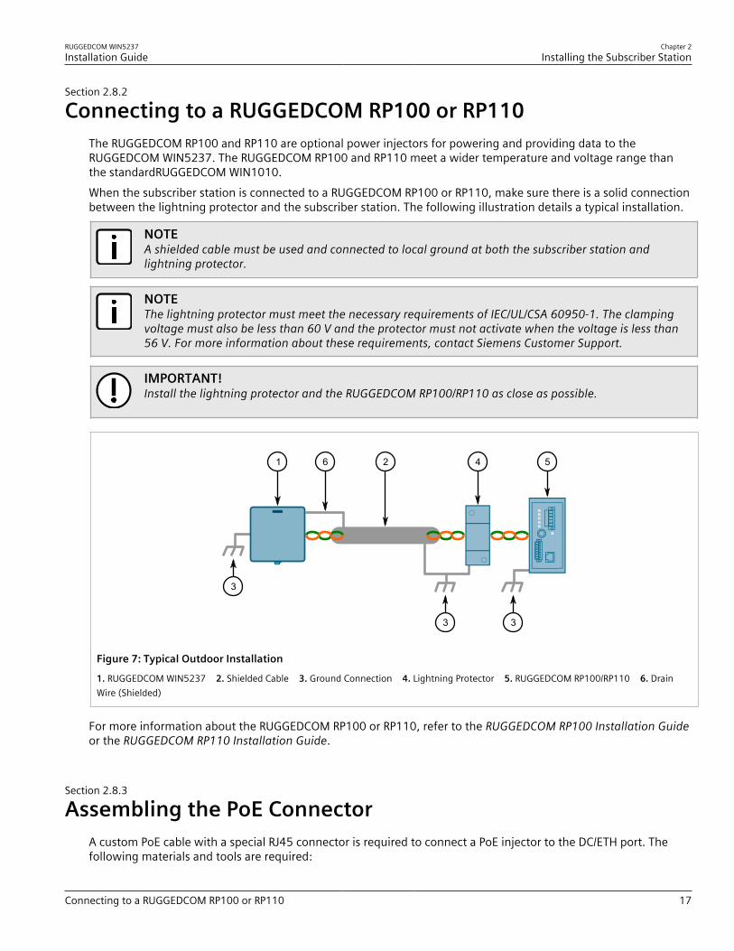
Connecting to a RUGGEDCOM RP100 or RP110The RUGGEDCOM RP100 and RP110 are optional power injectors for powering and providing data to theRUGGEDCOM WIN5237. The RUGGEDCOM RP100 and RP110 meet a wider temperature and voltage range thanthe standardRUGGEDCOM WIN1010.When the subscriber station is connected to a RUGGEDCOM RP100 or RP110, make sure there is a solid connectionbetween the lightning protector and the subscriber station. The following illustration details a typical installation.
NOTEA shielded cable must be used and connected to local ground at both the subscriber station andlightning protector.
NOTEThe lightning protector must meet the necessary requirements of IEC/UL/CSA 60950-1. The clampingvoltage must also be less than 60 V and the protector must not activate when the voltage is less than56 V. For more information about these requirements, contact Siemens Customer Support.
IMPORTANT!Install the lightning protector and the RUGGEDCOM RP100/RP110 as close as possible.
1
3
6
3 3
4 52
Figure 7: Typical Outdoor Installation
1. RUGGEDCOM WIN5237 2. Shielded Cable 3. Ground Connection 4. Lightning Protector 5. RUGGEDCOM RP100/RP110 6. DrainWire (Shielded)
For more information about the RUGGEDCOM RP100 or RP110, refer to the RUGGEDCOM RP100 Installation Guideor the RUGGEDCOM RP110 Installation Guide.
Section 2.8.3
Assembling the PoE ConnectorA custom PoE cable with a special RJ45 connector is required to connect a PoE injector to the DC/ETH port. Thefollowing materials and tools are required:
Chapter 2Installing the Subscriber Station
RUGGEDCOM WIN5237Installation Guide
18 Assembling the PoE Connector
• The RJ45 connector kit (included). Contains an RJ45 connector and loading bar.• CAT-5e cable of suitable length for your application. For information on cable specifications, refer to
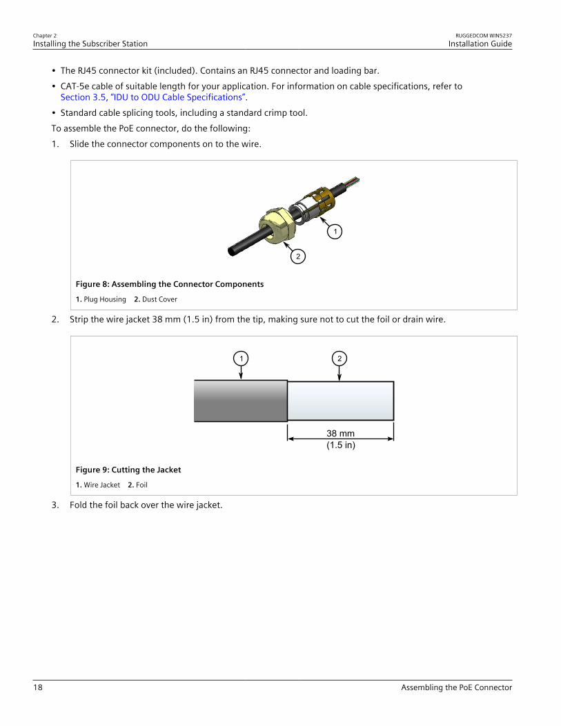
Section 3.5, “IDU to ODU Cable Specifications”.• Standard cable splicing tools, including a standard crimp tool.To assemble the PoE connector, do the following:1. Slide the connector components on to the wire.
1
2
Figure 8: Assembling the Connector Components
1. Plug Housing 2. Dust Cover
2. Strip the wire jacket 38 mm (1.5 in) from the tip, making sure not to cut the foil or drain wire.
38 mm(1.5 in)
1 2
Figure 9: Cutting the Jacket
1. Wire Jacket 2. Foil
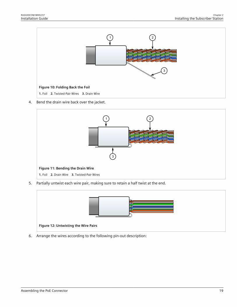
3. Fold the foil back over the wire jacket.
RUGGEDCOM WIN5237Installation Guide
Chapter 2Installing the Subscriber Station
Assembling the PoE Connector 19
1 2
3
Figure 10: Folding Back the Foil
1. Foil 2. Twisted-Pair Wires 3. Drain Wire
4. Bend the drain wire back over the jacket.
3
1 2
Figure 11: Bending the Drain Wire
1. Foil 2. Drain Wire 3. Twisted-Pair Wires
5. Partially untwist each wire pair, making sure to retain a half twist at the end.
Figure 12: Untwisting the Wire Pairs
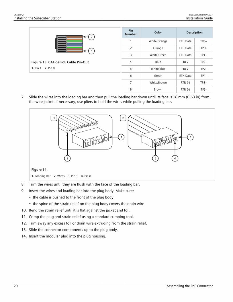
6. Arrange the wires according to the following pin-out description:
Chapter 2Installing the Subscriber Station
RUGGEDCOM WIN5237Installation Guide
20 Assembling the PoE Connector
1
2
Figure 13: CAT-5e PoE Cable Pin-Out1. Pin 1 2. Pin 8
PinNumber Color Description
1 White/Orange ETH Data TP0+
2 Orange ETH Data TP0-
3 White/Green ETH Data TP1+
4 Blue 48 V TP2+
5 White/Blue 48 V TP2-
6 Green ETH Data TP1-
7 White/Brown RTN (-) TP3+
8 Brown RTN (-) TP3-
7. Slide the wires into the loading bar and then pull the loading bar down until its face is 16 mm (0.63 in) fromthe wire jacket. If necessary, use pliers to hold the wires while pulling the loading bar.
1 2
2
1 1
3 4
1
1
2 3 4 5 6 7 8
23
45
67
8
Figure 14:
1. Loading Bar 2. Wires 3. Pin 1 4. Pin 8
8. Trim the wires until they are flush with the face of the loading bar.9. Insert the wires and loading bar into the plug body. Make sure:
• the cable is pushed to the front of the plug body• the spine of the strain relief on the plug body covers the drain wire
10. Bend the strain relief until it is flat against the jacket and foil.11. Crimp the plug and strain relief using a standard crimping tool.12. Trim away any excess foil or drain wire extruding from the strain relief.13. Slide the connector components up to the plug body.14. Insert the modular plug into the plug housing.

RUGGEDCOM WIN5237Installation Guide
Chapter 2Installing the Subscriber Station
Installing the Hazardous Location Kit 21
2
3
1
Figure 15: Assembling the Connector Components
1. PoE Plug 2. Plug Housing 3. Dust Cover
15. Align the latch with the LATCH slot.16. Press the plug into the plug housing until it bottoms out.17. While maintaining inward pressure on the plug or keeping the dust cover engaged, tighten the compression
nut to 0.56 N·m (5 In-lbs).
Section 2.8.4
Installing the Hazardous Location KitAn approved Power-over-Ethernet (PoE) injector is required when the subscriber station is installed in a hazardouslocation. The RUGGEDCOM WIN5237 is certified for installation in Class I, Division 2 Groups A, B, C and Dhazardous locations when installed using the Class I, Division 2 kit (P/N MKIT0090). The Class I, Division 2 kitcontains the following items:• Power supply unit• PoE injector• DC power cable• Open-ended AC power cableTo install the subscriber station in a hazardous location, do the following:1. Connect the DC power cable between the power supply unit and the PoE injector.
Chapter 2Installing the Subscriber Station
RUGGEDCOM WIN5237Installation Guide
22 Weatherproofing the Subscriber Station
41
6
2 23
5
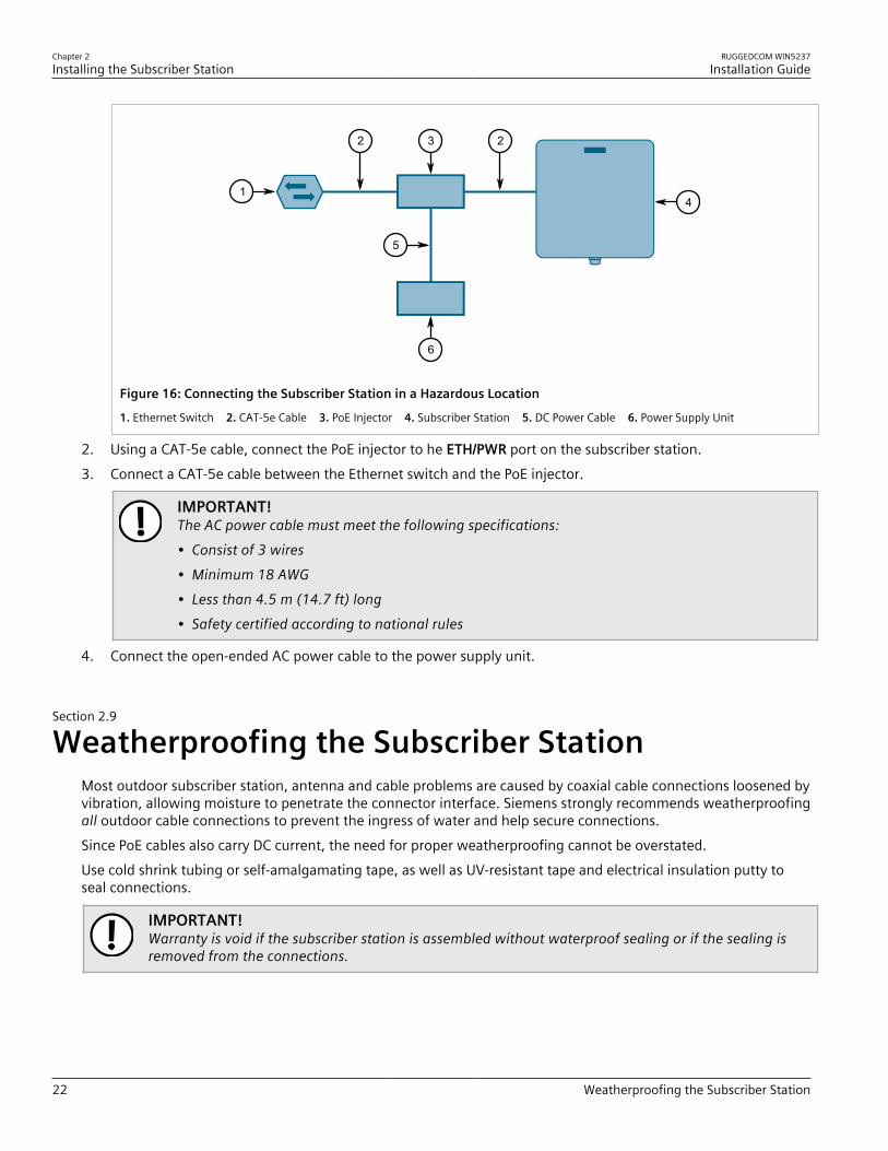
Figure 16: Connecting the Subscriber Station in a Hazardous Location
1. Ethernet Switch 2. CAT-5e Cable 3. PoE Injector 4. Subscriber Station 5. DC Power Cable 6. Power Supply Unit
2. Using a CAT-5e cable, connect the PoE injector to he ETH/PWR port on the subscriber station.3. Connect a CAT-5e cable between the Ethernet switch and the PoE injector.
IMPORTANT!The AC power cable must meet the following specifications:• Consist of 3 wires• Minimum 18 AWG• Less than 4.5 m (14.7 ft) long• Safety certified according to national rules
4. Connect the open-ended AC power cable to the power supply unit.
Section 2.9
Weatherproofing the Subscriber StationMost outdoor subscriber station, antenna and cable problems are caused by coaxial cable connections loosened byvibration, allowing moisture to penetrate the connector interface. Siemens strongly recommends weatherproofingall outdoor cable connections to prevent the ingress of water and help secure connections.Since PoE cables also carry DC current, the need for proper weatherproofing cannot be overstated.Use cold shrink tubing or self-amalgamating tape, as well as UV-resistant tape and electrical insulation putty toseal connections.
IMPORTANT!Warranty is void if the subscriber station is assembled without waterproof sealing or if the sealing isremoved from the connections.
RUGGEDCOM WIN5237Installation Guide
Chapter 2Installing the Subscriber Station
Weatherproofing a Cable 23
IMPORTANT!The method of weatherproofing described in this section must be completed on all externalconnections. If surge arrestors are used, all associated connections and arrestors must be completelywrapped with splicing tape or self-amalgamating tape.
CONTENTS• Section 2.9.1, “Weatherproofing a Cable”• Section 2.9.2, “Applying Cold Shrink Tubing”• Section 2.9.3, “Applying Self-Amalgamating Tape”
Section 2.9.1
Weatherproofing a CableTo weatherproof a cable, do the following:
IMPORTANT!PVC tape, silicon sealant and glue are not recommended for weatherproofing, as these materials aredifficult to apply accurately and are difficult to remove.
1. Spray the cable end and connector with a cleaner and de-greaser, making sure to remove any excess with aclean lint-free cloth.
2. Spray the cable end and connector with SCC3 conformal coating and allow them to dry fully (approximately 3to 5 minutes depending on the ambient temperature).
3. Apply cold shrink or self-amalgamating tape to the connector end. For information about how to applythese types of seals, refer to Section 2.9.2, “Applying Cold Shrink Tubing” or Section 2.9.3, “Applying Self-Amalgamating Tape”.
4. Apply two layers of UV-resistant vinyl tape to the cable ends.5. Apply electrical insulation putty around the very end of the cable to form a seal between it and the base
station.6. If the subscriber station is installed in a marine environment (e.g. wind farm substation, coastal tower, or
marine vessel) apply a coating of marine grease to all galvanized steel components, including mountingbrackets, nuts, washers and screws. This is in addition to the anti-corrosion spray applied during themounting process.
IMPORTANT!Should a cable need to be replaced, make sure all surfaces are thoroughly cleaned with a cleaner andde-greaser spray before connecting the new cable. No residue from the previous weatherproofingmaterials should be evident on the connector or the subscriber station chassis.
Section 2.9.2
Applying Cold Shrink TubingTo apply cold shrink tubing to a cable end, do the following:1. Disconnect the cable and slide the tube over the connector end.
Chapter 2Installing the Subscriber Station
RUGGEDCOM WIN5237Installation Guide
24 Applying Self-Amalgamating Tape
2. Reconnect the cable and slide the tube up to meet the subscriber station chassis.3. Hold the tube against the subscriber station chassis and start rotating it clockwise while gently pulling out the
core. Stop rotating once the front end of the cold shrink has begun to form around the cable end.4. Continue to remove the core in a counter-clockwise direction until it is completely removed.
Section 2.9.3
Applying Self-Amalgamating TapeTo apply self-amalgamating (or self-fusing) tape to a cable end, do the following:
IMPORTANT!When applying self-amalgamating tape, make sure to stretch it to 2/3 of its original width to form atight seal.
1. Cut a strip of self-amalgamating tape approximately 50 cm (19.7 in) long.2. Apply one end of the tape to the cable end and tightly wrap it around the cable once fully, making sure the
tape overlaps.3. Tightly wrap the remainder of the tape down the cable, making sure the tape overlaps with each pass.4. Repeat the previous steps to apply a second layer of tape.
Section 2.10
Configuring the Subscriber StationOnce the subscriber station is installed and connected to the network, it must be configured. The RUGGEDCOMWIN5237 features a Web-based User Interface (UI) for all configuration management. For more information aboutconfiguring the subscriber station, refer to the RUGGEDCOM WIN Subscriber Station User Guide associated withthe subscriber station and the installed software release.
RUGGEDCOM WIN5237Installation Guide
Chapter 3Technical Specifications
Power Consumption 25
Technical SpecificationsThis section provides important technical specifications related to the subscriber station.
CONTENTS• Section 3.1, “Power Consumption”• Section 3.2, “Radio and Modem Specifications”• Section 3.3, “Operating Environment”• Section 3.4, “Mechanical Specifications”• Section 3.5, “IDU to ODU Cable Specifications”
Section 3.1
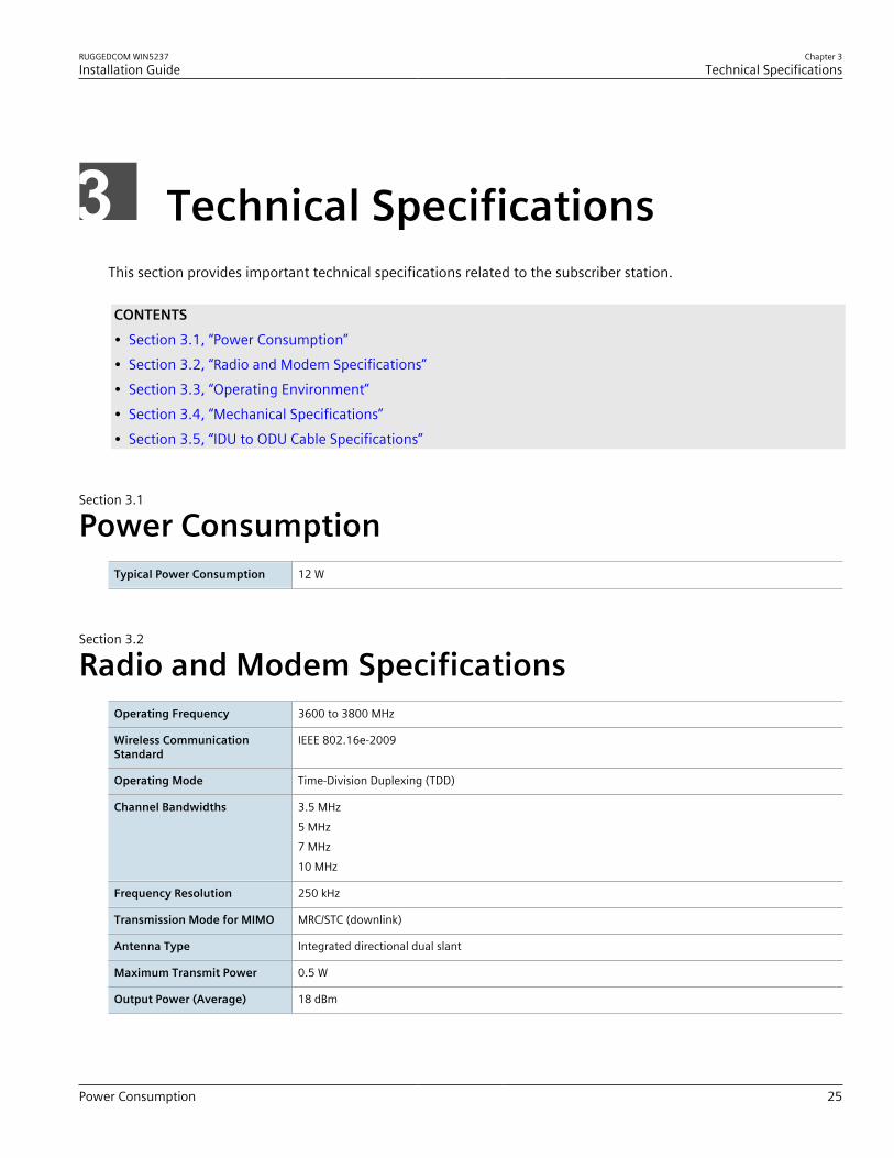
Power ConsumptionTypical Power Consumption 12 W
Section 3.2
Radio and Modem SpecificationsOperating Frequency 3600 to 3800 MHz
Wireless CommunicationStandard
IEEE 802.16e-2009
Operating Mode Time-Division Duplexing (TDD)
Channel Bandwidths 3.5 MHz5 MHz7 MHz10 MHz
Frequency Resolution 250 kHz
Transmission Mode for MIMO MRC/STC (downlink)
Antenna Type Integrated directional dual slant
Maximum Transmit Power 0.5 W
Output Power (Average) 18 dBm
Chapter 3Technical Specifications
RUGGEDCOM WIN5237Installation Guide
26 Operating Environment
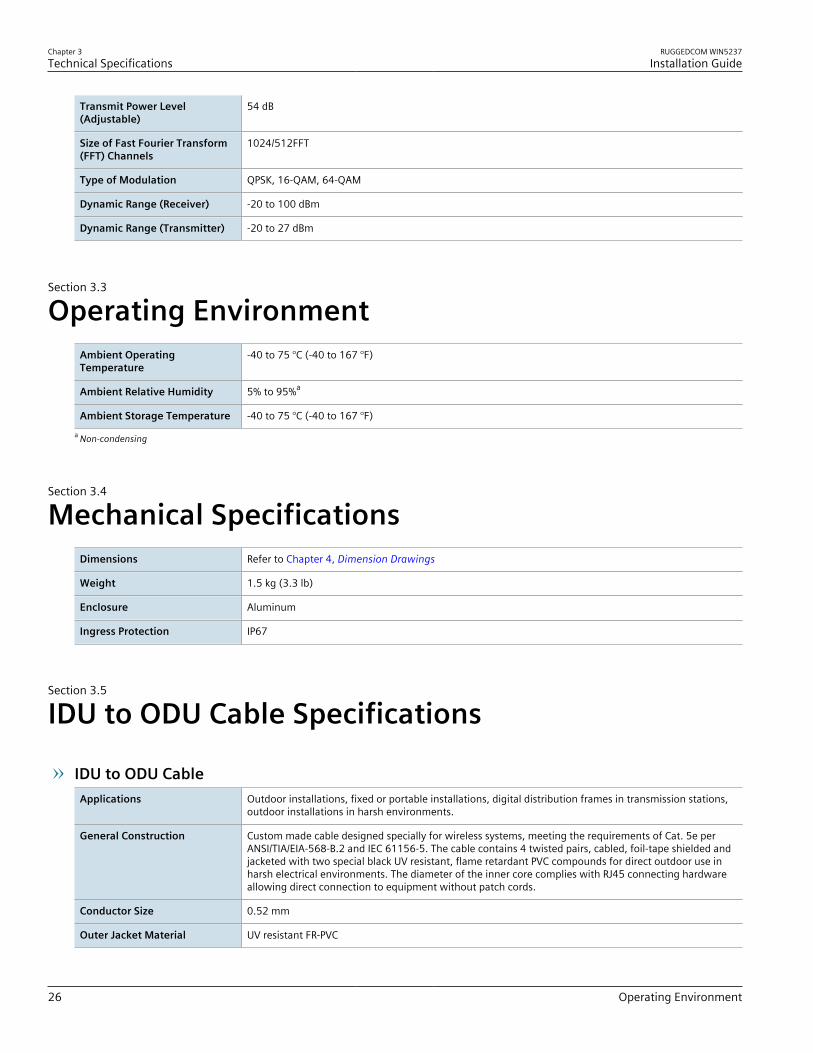
Transmit Power Level(Adjustable)
54 dB
Size of Fast Fourier Transform(FFT) Channels
1024/512FFT
Type of Modulation QPSK, 16-QAM, 64-QAM
Dynamic Range (Receiver) -20 to 100 dBm
Dynamic Range (Transmitter) -20 to 27 dBm
Section 3.3
Operating EnvironmentAmbient OperatingTemperature
-40 to 75 °C (-40 to 167 °F)
Ambient Relative Humidity 5% to 95%a
Ambient Storage Temperature -40 to 75 °C (-40 to 167 °F)a Non-condensing
Section 3.4
Mechanical SpecificationsDimensions Refer to Chapter 4, Dimension Drawings
Weight 1.5 kg (3.3 lb)
Enclosure Aluminum
Ingress Protection IP67
Section 3.5
IDU to ODU Cable Specifications
IDU to ODU CableApplications Outdoor installations, fixed or portable installations, digital distribution frames in transmission stations,
outdoor installations in harsh environments.
General Construction Custom made cable designed specially for wireless systems, meeting the requirements of Cat. 5e perANSI/TIA/EIA-568-B.2 and IEC 61156-5. The cable contains 4 twisted pairs, cabled, foil-tape shielded andjacketed with two special black UV resistant, flame retardant PVC compounds for direct outdoor use inharsh electrical environments. The diameter of the inner core complies with RJ45 connecting hardwareallowing direct connection to equipment without patch cords.
Conductor Size 0.52 mm
Outer Jacket Material UV resistant FR-PVC
RUGGEDCOM WIN5237Installation Guide
Chapter 3Technical Specifications
IDU to ODU Cable Specifications 27
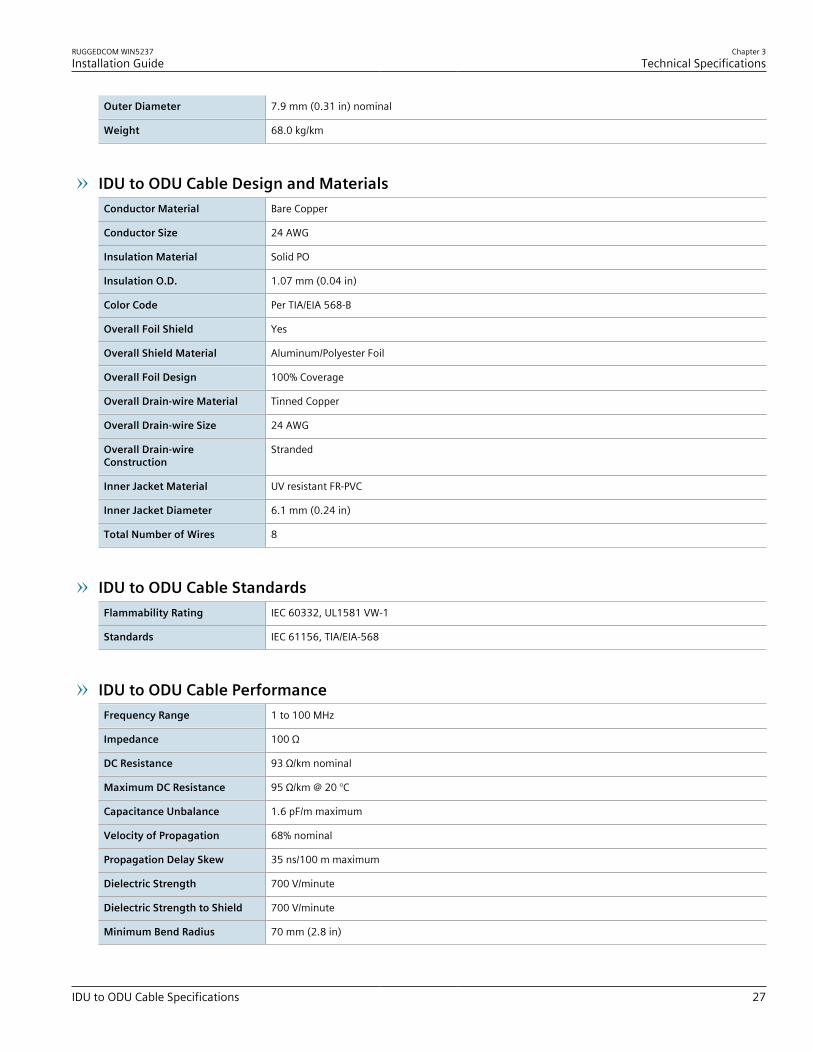
Outer Diameter 7.9 mm (0.31 in) nominal
Weight 68.0 kg/km
IDU to ODU Cable Design and MaterialsConductor Material Bare Copper
Conductor Size 24 AWG
Insulation Material Solid PO
Insulation O.D. 1.07 mm (0.04 in)
Color Code Per TIA/EIA 568-B
Overall Foil Shield Yes
Overall Shield Material Aluminum/Polyester Foil
Overall Foil Design 100% Coverage
Overall Drain-wire Material Tinned Copper
Overall Drain-wire Size 24 AWG
Overall Drain-wireConstruction
Stranded
Inner Jacket Material UV resistant FR-PVC
Inner Jacket Diameter 6.1 mm (0.24 in)
Total Number of Wires 8
IDU to ODU Cable StandardsFlammability Rating IEC 60332, UL1581 VW-1
Standards IEC 61156, TIA/EIA-568
IDU to ODU Cable PerformanceFrequency Range 1 to 100 MHz
Impedance 100 Ω
DC Resistance 93 Ω/km nominal
Maximum DC Resistance 95 Ω/km @ 20 °C
Capacitance Unbalance 1.6 pF/m maximum
Velocity of Propagation 68% nominal
Propagation Delay Skew 35 ns/100 m maximum
Dielectric Strength 700 V/minute
Dielectric Strength to Shield 700 V/minute
Minimum Bend Radius 70 mm (2.8 in)

Chapter 3Technical Specifications
RUGGEDCOM WIN5237Installation Guide
28 IDU to ODU Cable Specifications
Operating Temperature Range -40 to 70 °C (-40 to 158 °F)
RUGGEDCOM WIN5237Installation Guide
Chapter 4Dimension Drawings
29
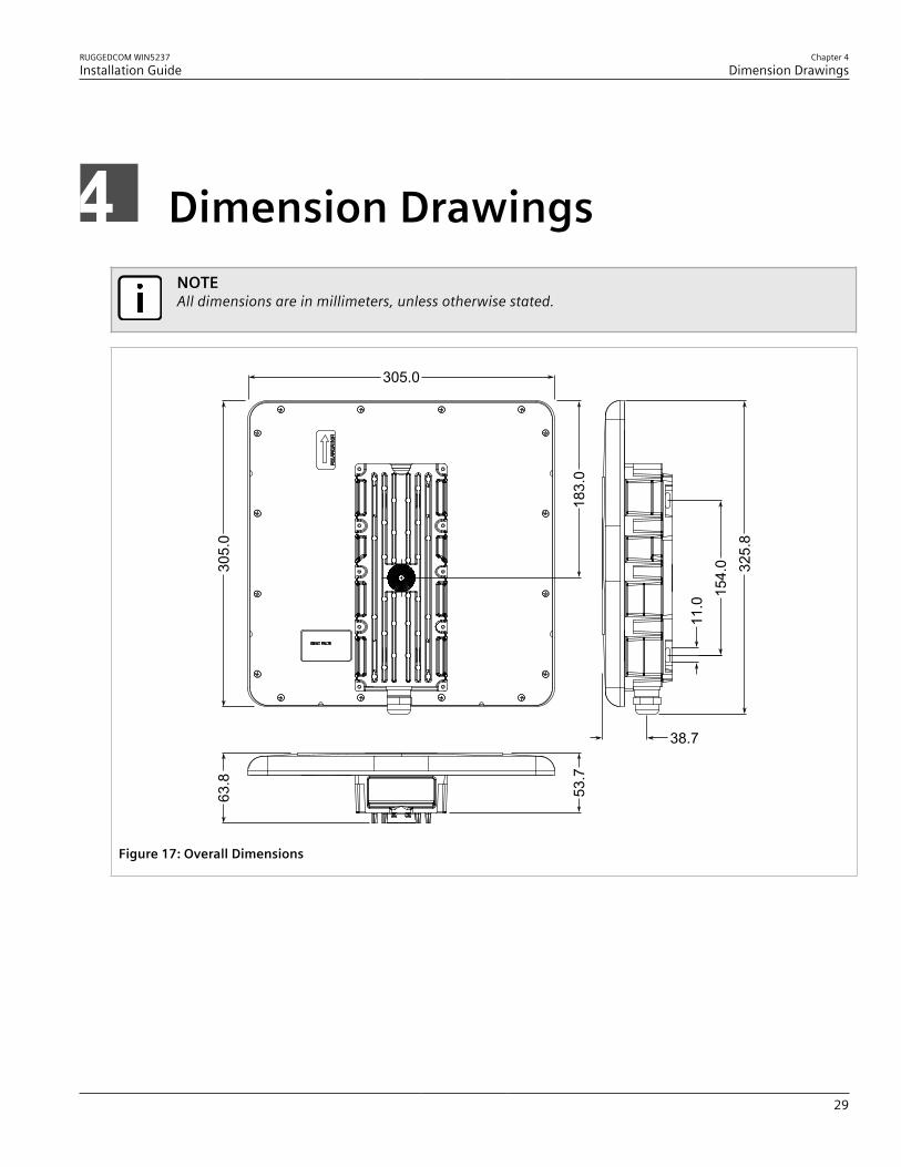
Dimension DrawingsNOTEAll dimensions are in millimeters, unless otherwise stated.
305.0
305.
0
11.0
154.
0 325.
8
183.
0
38.7
63.8
53.7
Figure 17: Overall Dimensions

Chapter 4Dimension Drawings
RUGGEDCOM WIN5237Installation Guide
30
RUGGEDCOM WIN5237Installation Guide
Chapter 5Certification
Approvals 31
CertificationThe RUGGEDCOM WIN5237 ODU CPE has been thoroughly tested to guarantee its conformance with recognizedstandards and has received approval from recognized regulatory agencies.
CONTENTS• Section 5.1, “Approvals”• Section 5.2, “Environmental Type Tests”
Section 5.1
ApprovalsThis section details the standards to which the RUGGEDCOM WIN5237 complies.
CONTENTS• Section 5.1.1, “MET Laboratories”• Section 5.1.2, “CSA”• Section 5.1.3, “European Union (EU)”• Section 5.1.4, “TÜV Rheinland”• Section 5.1.5, “ISED”• Section 5.1.6, “FCC”• Section 5.1.7, “IEEE”
Section 5.1.1
MET LaboratoriesThis subscriber station meets the requirements of the following standards:• Low Voltage Directive 2006/95/EC
Directive 2006/95/EC of the European Parliament and of the Council of 12 December 2006 on theHarmonisation of the Lawas of Member Stats Relating to Electrical Equipment Designed For Use Within CertainVoltage Limits
• EN 60079-0:2009Explosive Atmospheres – Equipment – General Requirements
• EN 60079-15:2010Explosive Atmospheres – Equipment Protection By Type of Protection "N"
Chapter 5Certification
RUGGEDCOM WIN5237Installation Guide
32 CSA
• UL 1604Electrical Equipment for Use in Class I and II, Division 2, and Class III Hazardous (Classified) Locations
• CAN/CSA-C22.2 No. 213-M1987Non-Incendive Electrical Equipment for Use in Class I, Division 2 Hazardous Locations
The subscriber station is marked with an MET classified mark that indicates compliance with both Canadian andU.S. requirements.
It is specifically approved for use in hazardous locations defined as:• Class I, Division 2, Groups A, B, C, D T4• Ex nA nC IIC T4 Gc• Class I, Zone 2, AEx/Ex nA nC IIC T4 GcNotices specific to MET Laboratories:
WARNING!EXPLOSION HAZARD• Substitution of components may impair suitability for Class I, Division 2• Do not disconnect equipment unless power has been switched off or the area is known to be non-
hazardous• Use only Lambda DPP50-48 Power Supply in conjunction with the unit
AVERTISSEMENT !RISQUE D’EXPLOSION• La substitution decomposants peut rendre ce matériel inacceptable pour les emplacements de Classe
I, Division 2• Avant de déconnecter l’equipment, couper le courant ou s’assurer que l’emplacement est désigné
non dangereux• Utilisez l’unité uniquement avec une batterie de la marque Lamba DPP50-48
Section 5.1.2
CSAThis subscriber station meets the requirements of the following Canadian Standards Association (CSA) standards:• CAN/CSA-C22.2 No. 60950-1-07+A1:2011+A2:2014
Information Technology Equipment – Safety – Part 1: General Requirements (Bi-National Standard, with UL60950-1)
• CAN/CSA-C22.2 No. 60950-22-07+GI1:2012Information Technology Equipment – Safety – Part 22: Equipment to be Installed Outdoors (Bi-Nationalstandard, with UL 60950-22)

RUGGEDCOM WIN5237Installation Guide
Chapter 5Certification
European Union (EU) 33
Section 5.1.3
European Union (EU)This subscriber station is declared by Siemens Canada Ltd to comply with essential requirements and otherrelevant provisions of the following EU directives:• IEC/EN 60950-1
Information Technology Equipment – Safety – Part 1: General Requirements
Section 5.1.4
TÜV RheinlandThis subscriber station is certified by TÜV Rheinland to meet the requirements of the following standards:• UL 60950-1:2007 R10.14
Information Technology Equipment – Safety – Part 1: General Requirements• UL 60950-22:2007 R12.11
Information Technology Equipment – Safety – Part 22: Equipment to be Installed OutdoorsThe subscriber station is marked with a TÜV Rheinland marking and can be used throughout the Europeancommunity.
A copy of the TÜV Rheinland Declaration of Conformity is available from Siemens Canada Ltd. For contactinformation, refer to “Contacting Siemens”.
Section 5.1.5
ISEDThis subscriber station is declared by Siemens Canada Ltd to meet the requirements of the following ISED(Innovation Science and Economic Development Canada) standard:• RSS-197
Wireless Broadband Access Equipment Operating in the Band 3650–3700 MHz
Section 5.1.6
FCCThis device has been tested and found to comply with the limits for a Class B digital device, pursuant to Part15 Subpart B and Part 90 of the FCC Rules. These limits are designed to provide reasonable protection againstharmful interference when the device is operated in a commercial environment.This device generates, uses and can radiate radio frequency energy and, if not installed and used in accordancewith the instruction manual, may cause harmful interference to radio communications. However, there is noguarantee that interference will not occur in a particular installation. If this device does cause harmful interference

Chapter 5Certification
RUGGEDCOM WIN5237Installation Guide
34 IEEE
to radio or television reception, which can be determined by turning the device off and on, the user is encouragedto try to correct the interference by one or more of the following measures:• Reorient or relocate the receiving antenna• Increase the separation between the device and receiver.• Connect the device into an outlet on a circuit different from that to which the receiver is connected• Contact Siemens Customer Support for assistance
IMPORTANT!Changes or modifications not expressly approved by the party responsible for compliance could voidthe user's authority to operate this device.
Section 5.1.7
IEEEThis subscriber station complies with the Mobile WiMAX Forum Wave 2 requirements defined by the followingInstitute of Electrical and Electronics Engineers (IEEE) standards:• IEEE 802.16-2005
IEEE Standard for Local and Metropolitan Area Networks – Part 16: Air Interface for Fixed and Mobile BroadbandWireless Access Systems – Amendment for Physical and Medium Access Control Layers for Combined Fixed andMobile Operation in Licensed Bands
Section 5.2
Environmental Type TestsThe RUGGEDCOM WIN5237 has passed the following environmental tests.
Test Description Test Levels
IEC 60068-2-1 Low Temperature -25 °C for 72 hours-40 °C (-40 °F) for 16 hours-40 °C (-40 °F) for 72 hours
IEC 60068-2-2 High Temperature 55 °C (131 °F) for 72 hours60 °C (140 °F) for 16 hours70 °C (158 °F) for 72 hours
IEC 60068-2-11MIL-STD-810F 509.4
Salt Fog 5% NaCI 35° 48h
IEC 60068-2-14 Temperature Change -10 to 45 °C (14 to 113 °F) @ 0.5 °C/min (0.9 °F/min) for 2 cycles-40 to -30 °C (-40 to -22 °F) @ 1 °C/min (1.8 °F/min) for 5 cycles
Water (Rain, Intensity) 0.01 m³/min (0.35 ft³/min @ 90 kPa (13 PSI) for 30 minutesIEC 60068-2-18IEC 529 (IP65/IP67) Water (Rain) 0.01 m³/min @ 90 kPa (13 PSI) for 15 minutes
IEC 60068-2-6 Sine Vibration Velocity: 5 mm/sDisplacement: 1.5 mm
Acceleration: 2 m/s²

RUGGEDCOM WIN5237Installation Guide
Chapter 5Certification
Environmental Type Tests 35
Test Description Test Levels
Frequency Range: 5 to 62 Hz, 62 to 200 Hz3 Axes
Duration: 3x5 sweep
Random Vibration (Class 4M5) ASD: 0.04 m²/s³12 to 12 dB/oct
Frequency Range: 5 to 10 Hz, 10 to 50, 50 to 100 Hz3 axes, 30 min per axes
IEC 60068-2-64
Random Vibration ASD: 1 m²/s³-3 dB/oct
Frequency Range: 5 to 20 Hz, 20 to 200 Hz3 axes, 30 min per axes
Shock (Class 4M5) Spectrum: Half sineDuration: 11 ms
Accelerator: 50 m/s²100 shocks in each direction
IEC 60068-2-29
Shock Spectrum: Half sineDuration: 6 ms
Accelerator: 180 m/s²100 shocks in each direction
IEC 60068-2-32Nebs: GR63
Free Fall Height: 1 m (3.3 ft)One fall on 3 faces, 3 edges and 4 corners
30 °C (86 °F) @ 90 to 100% for 2 cyclesIEC 60068-2-30 Humidity (Cycling)
40 °C (104 °F) @ 90 to 100% for 2 cycles

Chapter 5Certification
RUGGEDCOM WIN5237Installation Guide
36 Environmental Type Tests