Embed Size (px)
DESCRIPTION
Optical networking
Citation preview
A tutorial handbook
of advanced SONET
networking concepts

AT A G L A N C E
Introduction to SONET NetworkingOctober 30, 1996
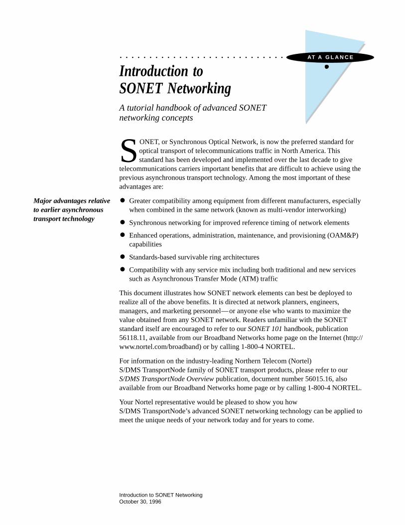
Introduction toSONET NetworkingA tutorial handbook of advanced SONETnetworking concepts
SONET, or Synchronous Optical Network, is now the preferred standard foroptical transport of telecommunications traffic in North America. Thisstandard has been developed and implemented over the last decade to give
telecommunications carriers important benefits that are difficult to achieve using theprevious asynchronous transport technology. Among the most important of theseadvantages are:
• Greater compatibility among equipment from different manufacturers, especiallywhen combined in the same network (known as multi-vendor interworking)
• Synchronous networking for improved reference timing of network elements
• Enhanced operations, administration, maintenance, and provisioning (OAM&P)capabilities
• Standards-based survivable ring architectures
• Compatibility with any service mix including both traditional and new servicessuch as Asynchronous Transfer Mode (ATM) traffic
This document illustrates how SONET network elements can best be deployed torealize all of the above benefits. It is directed at network planners, engineers,managers, and marketing personnel—or anyone else who wants to maximize thevalue obtained from any SONET network. Readers unfamiliar with the SONETstandard itself are encouraged to refer to our SONET 101 handbook, publication56118.11, available from our Broadband Networks home page on the Internet (http://www.nortel.com/broadband) or by calling 1-800-4 NORTEL.
For information on the industry-leading Northern Telecom (Nortel)S/DMS TransportNode family of SONET transport products, please refer to ourS/DMS TransportNode Overview publication, document number 56015.16, alsoavailable from our Broadband Networks home page or by calling 1-800-4 NORTEL.
Your Nortel representative would be pleased to show you howS/DMS TransportNode’s advanced SONET networking technology can be applied tomeet the unique needs of your network today and for years to come.
Major advantages relativeto earlier asynchronoustransport technology
ii
Introduction to SONET Networking1 SONET Networking Topologies, 1
2 Understanding OC-3 UPSRs, 9
3 Understanding Two-Fiber BLSRs, 13
4 Understanding Four-Fiber BLSRs, 21
5 Understanding Matched Nodes, 25
6 Wave Division Multiplexing, 29
7 Using SONET Rings to Manage Bandwidth inSmall-City Networks, 33
8 Acronyms and Abbreviations, 37
Contents
1
Introduction to SONET Networking
SONET Networking Topologies
Today’s SONET transport networks typically employ a number of different topolo-gies to satisfy important objectives for network simplicity, cost containment, band-width efficiency, and survivability. For example, an optical hubbing configurationmay be used to eliminate the need for a costly and complicated arrangement consist-ing of several back-to-back network elements. Similarly, a self-healing ring can bedeployed to assure service survivability through redundant, geographically diversepaths. This section defines each of the major SONET network element configura-tions and discusses their key attributes.
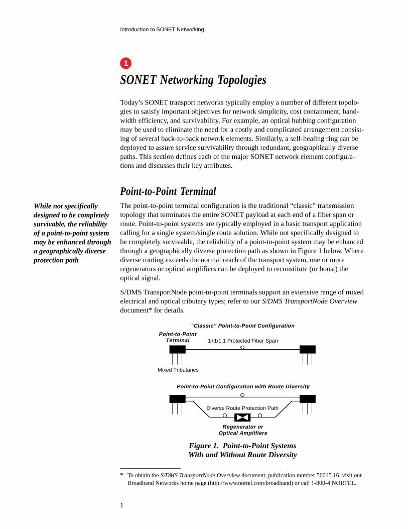
Point-to-Point TerminalThe point-to-point terminal configuration is the traditional “classic” transmissiontopology that terminates the entire SONET payload at each end of a fiber span orroute. Point-to-point systems are typically employed in a basic transport applicationcalling for a single system/single route solution. While not specifically designed tobe completely survivable, the reliability of a point-to-point system may be enhancedthrough a geographically diverse protection path as shown in Figure 1 below. Wherediverse routing exceeds the normal reach of the transport system, one or moreregenerators or optical amplifiers can be deployed to reconstitute (or boost) theoptical signal.
S/DMS TransportNode point-to-point terminals support an extensive range of mixedelectrical and optical tributary types; refer to our S/DMS TransportNode Overviewdocument* for details.
Mixed Tributaries
Point-to-PointTerminal 1+1/1:1 Protected Fiber Span
Diverse Route Protection Path
“Classic” Point-to-Point Configuration
Point-to-Point Configuration with Route Diversity
Regenerator orOptical Amplifiers
Figure 1. Point-to-Point SystemsWith and Without Route Diversity
While not specificallydesigned to be completelysurvivable, the reliabilityof a point-to-point systemmay be enhanced througha geographically diverseprotection path
1
* To obtain the S/DMS TransportNode Overview document, publication number 56015.16, visit ourBroadband Networks home page (http://www.nortel.com/broadband) or call 1-800-4 NORTEL.
2
Introduction to SONET Networking
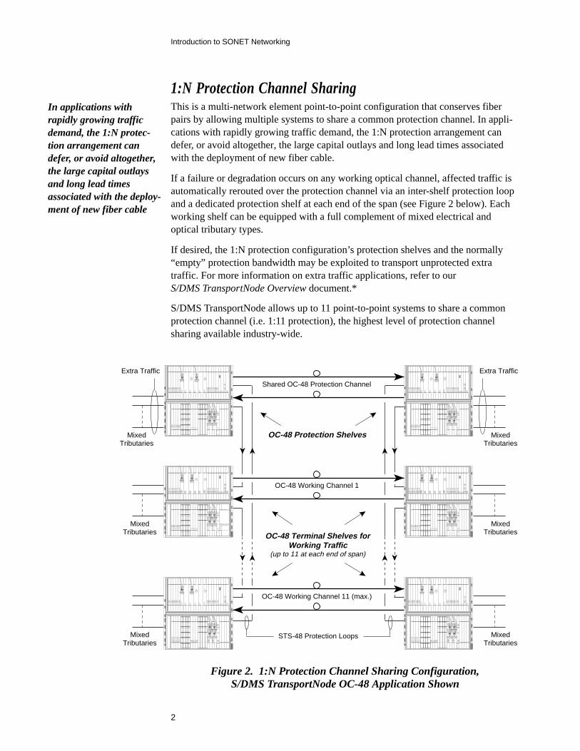
Figure 2. 1:N Protection Channel Sharing Configuration,S/DMS TransportNode OC-48 Application Shown
Shared OC-48 Protection Channel
OC-48 Working Channel 1
OC-48 Working Channel 11 (max.)
STS-48 Protection Loops
OC-48 Protection Shelves
OC-48 Terminal Shelves forWorking Traffic
(up to 11 at each end of span)
Extra Traffic
MixedTributaries
MixedTributaries
MixedTributaries
Extra Traffic
MixedTributaries
MixedTributaries
MixedTributaries
In applications withrapidly growing trafficdemand, the 1:N protec-tion arrangement candefer, or avoid altogether,the large capital outlaysand long lead timesassociated with the deploy-ment of new fiber cable
1:N Protection Channel SharingThis is a multi-network element point-to-point configuration that conserves fiberpairs by allowing multiple systems to share a common protection channel. In appli-cations with rapidly growing traffic demand, the 1:N protection arrangement candefer, or avoid altogether, the large capital outlays and long lead times associatedwith the deployment of new fiber cable.
If a failure or degradation occurs on any working optical channel, affected traffic isautomatically rerouted over the protection channel via an inter-shelf protection loopand a dedicated protection shelf at each end of the span (see Figure 2 below). Eachworking shelf can be equipped with a full complement of mixed electrical andoptical tributary types.
If desired, the 1:N protection configuration’s protection shelves and the normally“empty” protection bandwidth may be exploited to transport unprotected extratraffic. For more information on extra traffic applications, refer to ourS/DMS TransportNode Overview document.*
S/DMS TransportNode allows up to 11 point-to-point systems to share a commonprotection channel (i.e. 1:11 protection), the highest level of protection channelsharing available industry-wide.
3
Introduction to SONET Networking
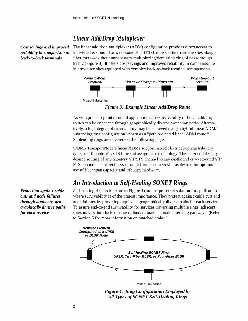
Linear Add/Drop MultiplexerThe linear add/drop multiplexer (ADM) configuration provides direct access toindividual eastbound or westbound VT/STS channels at intermediate sites along afiber route—without unnecessary multiplexing/demultiplexing of pass-throughtraffic (Figure 3). It offers cost savings and improved reliability in comparison tointermediate sites equipped with complex back-to-back terminal arrangements.
Mixed Tributaries
Point-to-PointTerminal Linear Add/Drop Multiplexers
Point-to-PointTerminal
As with point-to-point terminal applications, the survivability of linear add/droproutes can be enhanced through geographically diverse protection paths. Alterna-tively, a high degree of survivability may be achieved using a hybrid linear ADM/subtending ring configuration known as a ”path protected linear ADM route.”Subtending rings are covered on the following page.
S/DMS TransportNode’s linear ADMs support mixed electrical/optical tributarytypes and flexible VT/STS time slot assignment technology. The latter enables anydesired routing of any tributary VT/STS channel to any eastbound or westbound VT/STS channel—or direct pass-through from east to west—as desired for optimumuse of fiber span capacity and tributary hardware.
An Introduction to Self-Healing SONET RingsSelf-healing ring architectures (Figure 4) are the preferred solution for applicationswhere survivability is of the utmost importance. They protect against cable cuts andnode failures by providing duplicate, geographically diverse paths for each service.To assure end-to-end survivability for services traversing multiple rings, adjacentrings may be interlocked using redundant matched node inter-ring gateways. (Referto Section 5 for more information on matched nodes.)
Figure 3. Example Linear Add/Drop Route
Cost savings and improvedreliability in comparison toback-to-back terminals
Mixed Tributaries
Network ElementConfigured as a UPSR
or BLSR Node
Self-Healing SONET Ring,UPSR, Two-Fiber BLSR, or Four-Fiber BLSR
Figure 4. Ring Configuration Employed byAll Types of SONET Self-Healing Rings
Protection against cablecuts and node failuresthrough duplicate, geo-graphically diverse pathsfor each service
4
Introduction to SONET Networking
A SONET ring is generally of one of three types: a unidirectional path switched ring(UPSR), two-fiber bidirectional line switched ring (BLSR), or four-fiber BLSR.While each type of ring features fully self-healing operation, differing characteristicsmay make one architecture preferable in certain situations. For example, a two-fiberBLSR is a good choice for networks with a highly distributed “mesh” traffic pattern.
Table 1 below shows ideal applications for each SONET ring architecture, all ofwhich are supported by S/DMS TransportNode. Refer to Sections 2, 3, and 4 for anexplanation of the underlying technology associated with each ring.
Ring Architecture Best Used In How It Works
UPSR Access networks where mosttraffic terminates in a central officehub
Two-Fiber BLSR
See Section 2
Access and interoffice networkswith a highly distributed trafficpattern
See Section 3
Applications requiring extra-highcapacity and/or protection againstmultiple concurrent faults
See Section 4Four-Fiber BLSR
Table 1. Ring Architecture Comparison
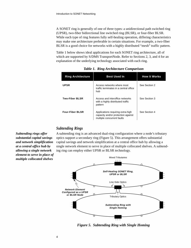
Subtending RingsA subtending ring is an advanced dual-ring configuration where a node’s tributaryoptics support a secondary ring (Figure 5). This arrangement offers substantialcapital savings and network simplification at a central office hub by allowing asingle network element to serve in place of multiple collocated shelves. A subtend-ing ring can employ either UPSR or BLSR technology.
Figure 5. Subtending Ring with Single Homing
Mixed Tributaries
Network ElementConfigured as a UPSR
or BLSR Node
Self-Healing SONET Ring,UPSR or BLSR
Subtending Ring withSingle Homing
Tributary Optics
Line-Side Optics
Subtending rings offersubstantial capital savingsand network simplificationat a central office hub byallowing a single networkelement to serve in place ofmultiple collocated shelves
5
Introduction to SONET Networking
Mixed Tributaries
Network ElementConfigured as a UPSR
or BLSR Node
Self-Healing SONET Ring,UPSR or BLSR
Subtending Ring withDual Homing
Tributary Optics
Line-Side Optics
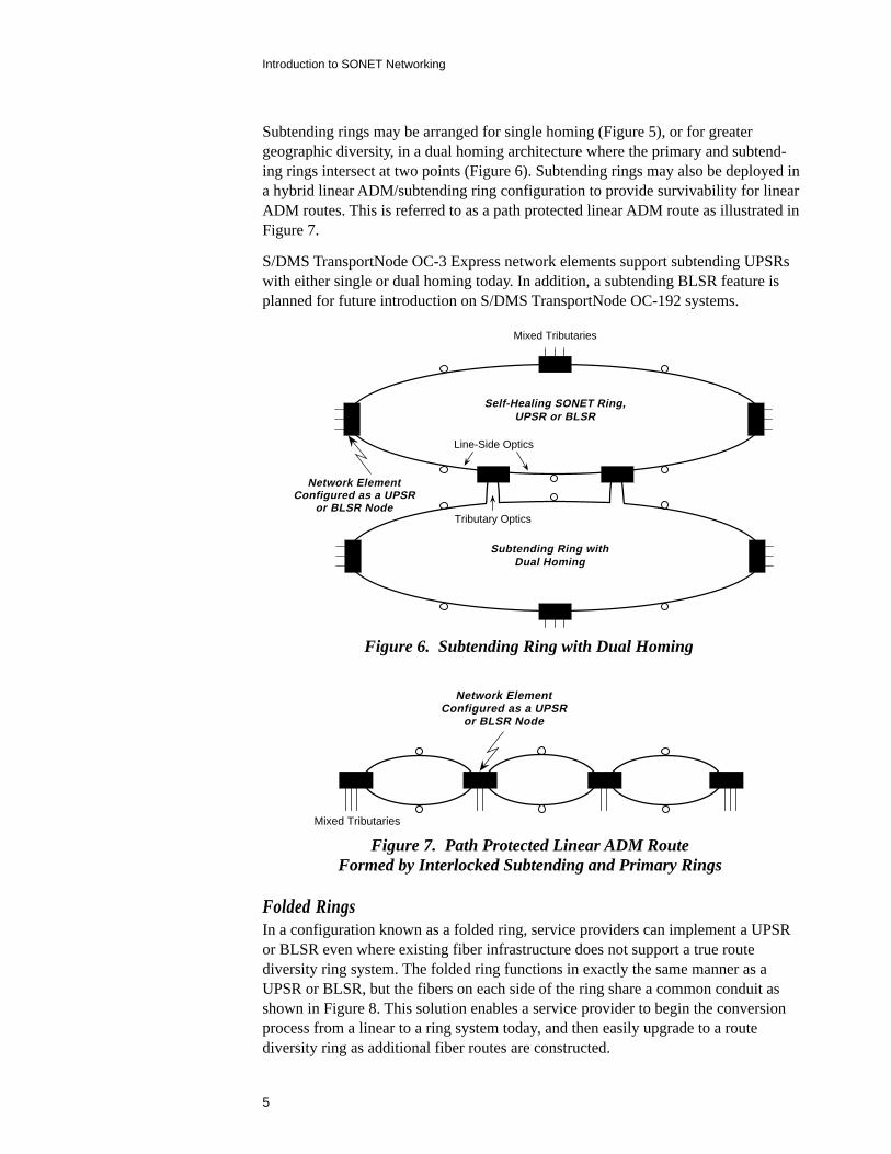
Figure 6. Subtending Ring with Dual Homing
Subtending rings may be arranged for single homing (Figure 5), or for greatergeographic diversity, in a dual homing architecture where the primary and subtend-ing rings intersect at two points (Figure 6). Subtending rings may also be deployed ina hybrid linear ADM/subtending ring configuration to provide survivability for linearADM routes. This is referred to as a path protected linear ADM route as illustrated inFigure 7.
S/DMS TransportNode OC-3 Express network elements support subtending UPSRswith either single or dual homing today. In addition, a subtending BLSR feature isplanned for future introduction on S/DMS TransportNode OC-192 systems.
Mixed Tributaries
Network ElementConfigured as a UPSR
or BLSR Node
Figure 7. Path Protected Linear ADM RouteFormed by Interlocked Subtending and Primary Rings
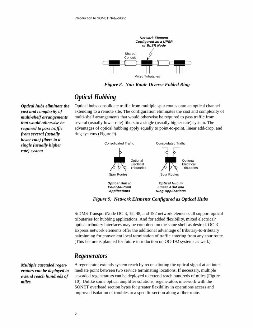
Folded RingsIn a configuration known as a folded ring, service providers can implement a UPSRor BLSR even where existing fiber infrastructure does not support a true routediversity ring system. The folded ring functions in exactly the same manner as aUPSR or BLSR, but the fibers on each side of the ring share a common conduit asshown in Figure 8. This solution enables a service provider to begin the conversionprocess from a linear to a ring system today, and then easily upgrade to a routediversity ring as additional fiber routes are constructed.
6
Introduction to SONET Networking
SharedConduit
Network ElementConfigured as a UPSR
or BLSR Node
Mixed Tributaries
Figure 8. Non-Route Diverse Folded Ring
Optical HubbingOptical hubs consolidate traffic from multiple spur routes onto an optical channelextending to a remote site. The configuration eliminates the cost and complexity ofmulti-shelf arrangements that would otherwise be required to pass traffic fromseveral (usually lower rate) fibers to a single (usually higher rate) system. Theadvantages of optical hubbing apply equally to point-to-point, linear add/drop, andring systems (Figure 9).
Optical Hub inPoint-to-PointApplications
Spur Routes Spur Routes
Consolidated Traffic Consolidated Traffic
OptionalElectricalTributaries
OptionalElectricalTributaries
Optical Hub inLinear ADM and
Ring Applications
Figure 9. Network Elements Configured as Optical Hubs
S/DMS TransportNode OC-3, 12, 48, and 192 network elements all support opticaltributaries for hubbing applications. And for added flexibility, mixed electrical/optical tributary interfaces may be combined on the same shelf as desired. OC-3Express network elements offer the additional advantage of tributary-to-tributaryhairpinning for convenient local termination of traffic entering from any spur route.(This feature is planned for future introduction on OC-192 systems as well.)
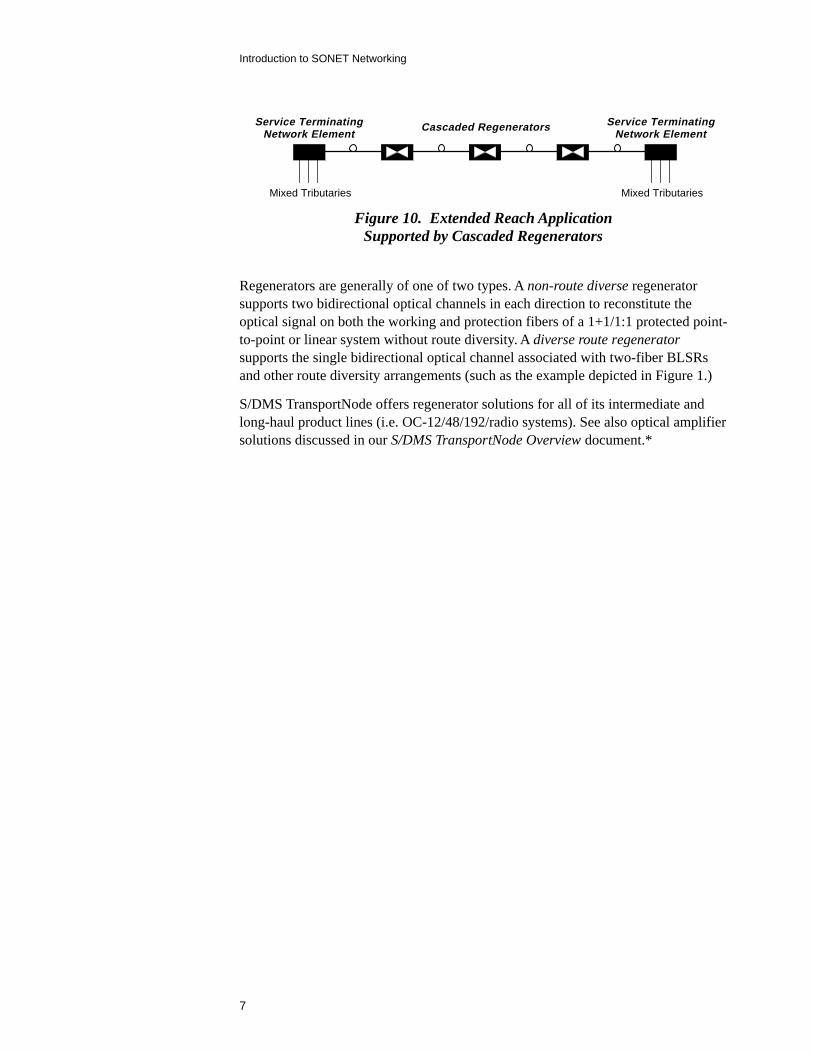
RegeneratorsA regenerator extends system reach by reconstituting the optical signal at an inter-mediate point between two service terminating locations. If necessary, multiplecascaded regenerators can be deployed to extend reach hundreds of miles (Figure10). Unlike some optical amplifier solutions, regenerators interwork with theSONET overhead section bytes for greater flexibility in operations access andimproved isolation of troubles to a specific section along a fiber route.
Optical hubs eliminate thecost and complexity ofmulti-shelf arrangementsthat would otherwise berequired to pass trafficfrom several (usuallylower rate) fibers to asingle (usually higherrate) system
Multiple cascaded regen-erators can be deployed toextend reach hundreds ofmiles
7
Introduction to SONET Networking
Mixed Tributaries
Service TerminatingNetwork Element
Cascaded Regenerators
Mixed Tributaries
Service TerminatingNetwork Element
Figure 10. Extended Reach ApplicationSupported by Cascaded Regenerators
Regenerators are generally of one of two types. A non-route diverse regeneratorsupports two bidirectional optical channels in each direction to reconstitute theoptical signal on both the working and protection fibers of a 1+1/1:1 protected point-to-point or linear system without route diversity. A diverse route regeneratorsupports the single bidirectional optical channel associated with two-fiber BLSRsand other route diversity arrangements (such as the example depicted in Figure 1.)
S/DMS TransportNode offers regenerator solutions for all of its intermediate andlong-haul product lines (i.e. OC-12/48/192/radio systems). See also optical amplifiersolutions discussed in our S/DMS TransportNode Overview document.*

9
Introduction to SONET Networking
Understanding OC-3 UPSRs
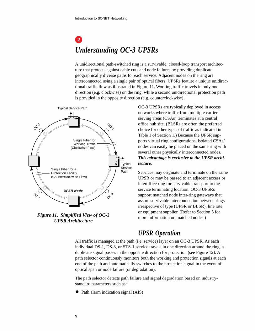
A unidirectional path-switched ring is a survivable, closed-loop transport architec-ture that protects against cable cuts and node failures by providing duplicate,geographically diverse paths for each service. Adjacent nodes on the ring areinterconnected using a single pair of optical fibers. UPSRs feature a unique unidirec-tional traffic flow as illustrated in Figure 11. Working traffic travels in only onedirection (e.g. clockwise) on the ring, while a second unidirectional protection pathis provided in the opposite direction (e.g. counterclockwise).
OC-3 UPSRs are typically deployed in accessnetworks where traffic from multiple carrierserving areas (CSAs) terminates at a centraloffice hub site. (BLSRs are often the preferredchoice for other types of traffic as indicated inTable 1 of Section 1.) Because the UPSR sup-ports virtual ring configurations, isolated CSAs/nodes can easily be placed on the same ring withseveral other physically interconnected nodes.This advantage is exclusive to the UPSR archi-tecture.
Services may originate and terminate on the sameUPSR or may be passed to an adjacent access orinteroffice ring for survivable transport to theservice terminating location. OC-3 UPSRssupport matched node inter-ring gateways thatassure survivable interconnection between ringsirrespective of type (UPSR or BLSR), line rate,or equipment supplier. (Refer to Section 5 formore information on matched nodes.)
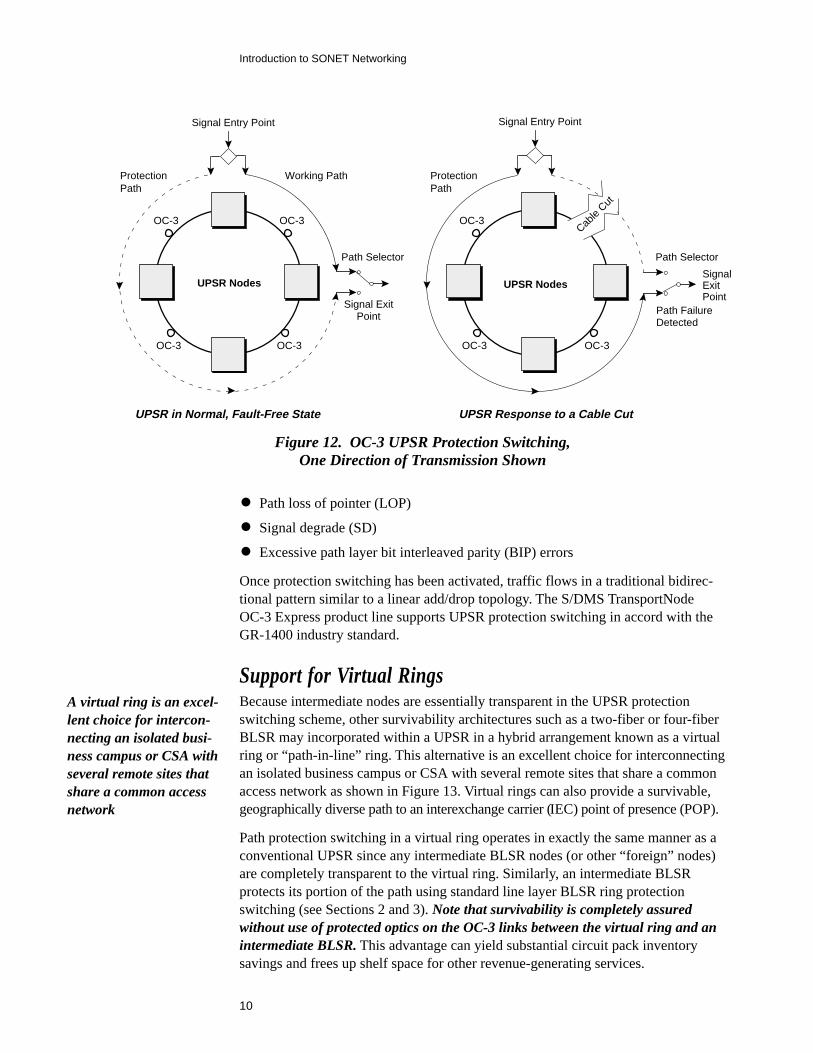
UPSR OperationAll traffic is managed at the path (i.e. service) layer on an OC-3 UPSR. As eachindividual DS-1, DS-3, or STS-1 service travels in one direction around the ring, aduplicate signal passes in the opposite direction for protection (see Figure 12). Apath selector continuously monitors both the working and protection signals at eachend of the path and automatically switches to the protection signal in the event ofoptical span or node failure (or degradation).
The path selector detects path failure and signal degradation based on industry-standard parameters such as:
• Path alarm indication signal (AIS)
OC-3
OC-3
UPSR Node
Single Fiber forWorking Traffic
(Clockwise Flow)
Single Fiber for aProtection Facility(Counterclockwise Flow)
O
C-3
OC-3
Typical Service Path
TypicalServicePath
Figure 11. Simplified View of OC-3UPSR Architecture
2
10
Introduction to SONET Networking
• Path loss of pointer (LOP)
• Signal degrade (SD)
• Excessive path layer bit interleaved parity (BIP) errors
Once protection switching has been activated, traffic flows in a traditional bidirec-tional pattern similar to a linear add/drop topology. The S/DMS TransportNodeOC-3 Express product line supports UPSR protection switching in accord with theGR-1400 industry standard.
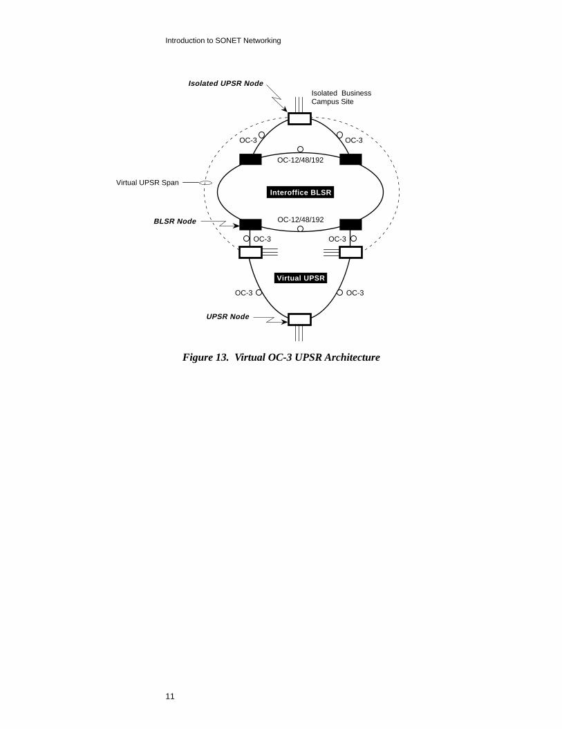
Support for Virtual RingsBecause intermediate nodes are essentially transparent in the UPSR protectionswitching scheme, other survivability architectures such as a two-fiber or four-fiberBLSR may incorporated within a UPSR in a hybrid arrangement known as a virtualring or “path-in-line” ring. This alternative is an excellent choice for interconnectingan isolated business campus or CSA with several remote sites that share a commonaccess network as shown in Figure 13. Virtual rings can also provide a survivable,geographically diverse path to an interexchange carrier (IEC) point of presence (POP).
Path protection switching in a virtual ring operates in exactly the same manner as aconventional UPSR since any intermediate BLSR nodes (or other “foreign” nodes)are completely transparent to the virtual ring. Similarly, an intermediate BLSRprotects its portion of the path using standard line layer BLSR ring protectionswitching (see Sections 2 and 3). Note that survivability is completely assuredwithout use of protected optics on the OC-3 links between the virtual ring and anintermediate BLSR. This advantage can yield substantial circuit pack inventorysavings and frees up shelf space for other revenue-generating services.
Signal Entry Point
Signal ExitPoint
Working PathProtectionPath
Signal Entry Point
SignalExitPoint
ProtectionPath
Path FailureDetected
UPSR Nodes
OC-3OC-3
OC-3 OC-3
Path Selector
Cable
Cut
Path Selector
OC-3
OC-3 OC-3
UPSR in Normal, Fault-Free State UPSR Response to a Cable Cut
UPSR Nodes
Figure 12. OC-3 UPSR Protection Switching,One Direction of Transmission Shown
A virtual ring is an excel-lent choice for intercon-necting an isolated busi-ness campus or CSA withseveral remote sites thatshare a common accessnetwork
11
Introduction to SONET Networking
Virtual UPSR
Interoffice BLSR
Isolated BusinessCampus Site
BLSR Node
UPSR Node
OC-3 OC-3
OC-12/48/192
OC-12/48/192
Virtual UPSR Span
Isolated UPSR Node
OC-3 OC-3
OC-3 OC-3
Figure 13. Virtual OC-3 UPSR Architecture

13
Introduction to SONET Networking
Bidirectional SpanConsisting of Two Fibers
Up to 16 Traffic TerminatingNetwork Elements
OC-12, 48, or 192
Rin
gpe
rim
eter measures up to 1200 km(746
miles)
Two-FiberBLSR Node
OC
-12, 48, or 192
Understanding Two-Fiber BLSRs
As with the OC-3 UPSR discussed in Section 2, the two-fiber bidirectional lineswitched ring is a survivable SONET transport architecture that protects againstcable cuts and node failures by providing duplicate, geographically diverse paths foreach service. With the ability to reuse bandwidth as traffic is added/dropped atvarious locations around the ring, two-fiber BLSRs are ideal for distributed “mesh”and node-to-adjacent-node traffic patterns typical of interoffice networks—andsometimes found in access networks as well.
To meet a wide range of capacity demands, S/DMS TransportNode offers two-fiberBLSRs operating at a choice of line rates: OC-12, OC-48, or OC-192, the mostcomprehensive portfolio available industry-wide. All S/DMS TransportNode two-fiber BLSRs comply with the latest GR-1230 industry standards and supportmatched node inter-ring gateways to assure survivability for services traversingmultiple interconnected rings. These gateways are fully interoperable with two-fiberBLSRs, four-fiber BLSRs, and UPSRs irrespective of line rate or equipment vendor.(Refer to Section 5 for more information on matched nodes.)
S/DMS TransportNode also offers BLSR configurations supporting extra traffic, afeature that enhances the revenue potential of existing fiber plant.
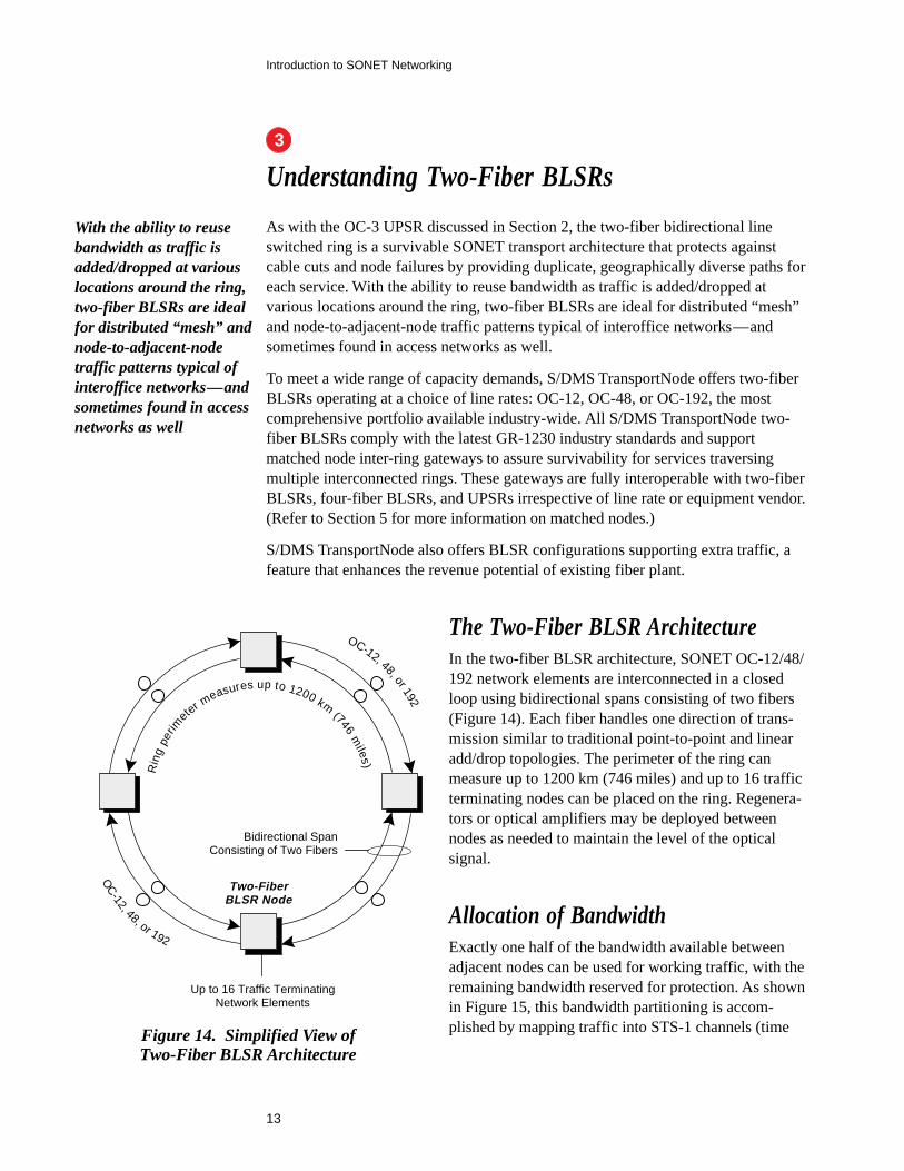
The Two-Fiber BLSR ArchitectureIn the two-fiber BLSR architecture, SONET OC-12/48/192 network elements are interconnected in a closedloop using bidirectional spans consisting of two fibers(Figure 14). Each fiber handles one direction of trans-mission similar to traditional point-to-point and linearadd/drop topologies. The perimeter of the ring canmeasure up to 1200 km (746 miles) and up to 16 trafficterminating nodes can be placed on the ring. Regenera-tors or optical amplifiers may be deployed betweennodes as needed to maintain the level of the opticalsignal.
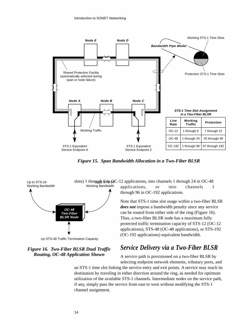
Allocation of BandwidthExactly one half of the bandwidth available betweenadjacent nodes can be used for working traffic, with theremaining bandwidth reserved for protection. As shownin Figure 15, this bandwidth partitioning is accom-plished by mapping traffic into STS-1 channels (timeFigure 14. Simplified View of
Two-Fiber BLSR Architecture
With the ability to reusebandwidth as traffic isadded/dropped at variouslocations around the ring,two-fiber BLSRs are idealfor distributed “mesh” andnode-to-adjacent-nodetraffic patterns typical ofinteroffice networks—andsometimes found in accessnetworks as well
3
14
Introduction to SONET Networking
Node B
Shared Protection Facility(automatically selected during
span or node failure)
Working Traffic
STS-1 EquivalentService Endpoint A
STS-1 EquivalentService Endpoint Z
Working STS-1 Time Slots
Protection STS-1 Time Slots
Bandwidth Pipe Model
Node A Node C
Node E Node D
LineRate
WorkingTraffic Protection
OC-12 1 through 6 7 through 12
OC-48 1 through 24 25 through 48
OC-192 1 through 96 97 through 192
STS-1 Time Slot Assignmentin a Two-Fiber BLSR
Figure 15. Span Bandwidth Allocation in a Two-Fiber BLSR
slots) 1 through 6 in OC-12 applications, into channels 1 through 24 in OC-48applications, or into channels 1through 96 in OC-192 applications.
Note that STS-1 time slot usage within a two-fiber BLSRdoes not impose a bandwidth penalty since any servicecan be routed from either side of the ring (Figure 16).Thus, a two-fiber BLSR node has a maximum fullyprotected traffic termination capacity of STS-12 (OC-12applications), STS-48 (OC-48 applications), or STS-192(OC-192 applications) equivalent bandwidth.
Service Delivery via a Two-Fiber BLSRA service path is provisioned on a two-fiber BLSR byselecting endpoint network elements, tributary ports, and
an STS-1 time slot linking the service entry and exit points. A service may reach itsdestination by traveling in either direction around the ring, as needed for optimumutilization of the available STS-1 channels. Intermediate nodes on the service path,if any, simply pass the service from east to west without modifying the STS-1channel assignment.
Up to STS-24Working Bandwidth
Up to STS-24Working Bandwidth
Up STS-48 Traffic Termination Capacity
OC-48Two-Fiber
BLSR Node
Figure 16. Two-Fiber BLSR Dual TrafficRouting, OC-48 Application Shown
15
Introduction to SONET Networking
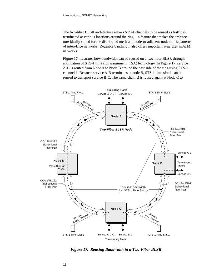
The two-fiber BLSR architecture allows STS-1 channels to be reused as traffic isterminated at various locations around the ring—a feature that makes the architec-ture ideally suited for the distributed mesh and node-to-adjacent-node traffic patternsof interoffice networks. Reusable bandwidth also offers important synergies in ATMnetworks.
Figure 17 illustrates how bandwidth can be reused on a two-fiber BLSR throughapplication of STS-1 time slot assignment (TSA) technology. In Figure 17, serviceA-B is routed from Node A to Node B around the east side of the ring using STS-1channel 1. Because service A-B terminates at node B, STS-1 time slot 1 can bereused to transport service B-C. The same channel is reused again at Node C to
Terminating Traffic
Service B-CService A-D-C
Node A
Node C
Node D
Terminating Traffic
TerminatingTraffic
1
1
Service A-D-C
Service A-B
Service B-C
Pass-ThroughTraffic
Service A-B
Service
A-BChannel
OC-12/48/192BidirectionalFiber Pair
OC-12/48/192BidirectionalFiber Pair
OC-12/48/192Bidirectional
Fiber Pair
OC-12/48/192Bidirectional
Fiber Pair “Reused” Bandwidth(i.e. STS-1 Time Slot 1)
Node B
STS-1 Time Slot 1
ServiceB-C Channel
STS-1 Time Slot 1
1
STS-1 Time Slot 1
A-D-CChannel
Service
1
STS-1 Time Slot 1
ServiceA-D-C Channel
Two-Fiber BLSR Node
Figure 17. Reusing Bandwidth in a Two-Fiber BLSR
16
Introduction to SONET Networking
transport service A-D-C. Node D passes service A-D-C through to Node A withoutmodifying its time slot assignment. Thus, the sample two-fiber bidirectional lineswitched ring of Figure 17 is able to transport traffic having STS-3 total band-width while using only a single STS-1 channel.
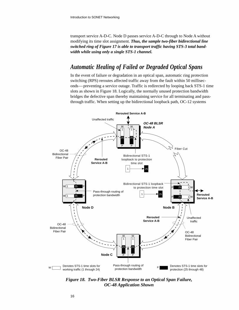
Automatic Healing of Failed or Degraded Optical SpansIn the event of failure or degradation in an optical span, automatic ring protectionswitching (RPS) reroutes affected traffic away from the fault within 50 millisec-onds—preventing a service outage. Traffic is redirected by looping back STS-1 timeslots as shown in Figure 18. Logically, the normally unused protection bandwidthbridges the defective span thereby maintaining service for all terminating and pass-through traffic. When setting up the bidirectional loopback path, OC-12 systems
Node C
Node D
Rerouted Service A-B
ReroutedService A-B
Fiber Cut
Bidirectional STS-1loopback to protection
time slot
Bidirectional STS-1 loopbackto protection time slot
Node B
OC-48 BLSRNode AW
P P
W
2525
W 25 P
W 25 P
W
P
25
P
W
25
W25P
W25P
1 25
1 25
Unaffected traffic
Pass-through routing ofprotection bandwidth
Pass-through routing ofprotection bandwidth
Unaffectedtraffic
OC-48Bidirectional
Fiber Pair OC-48BidirectionalFiber Pair
OC-48Bidirectional
Fiber Pair
W PDenotes STS-1 time slots forworking traffic (1 through 24)
Denotes STS-1 time slots forprotection (25 through 48)
ReroutedService A-B
ReroutedService A-B
1 1
1
1
1 1
1
1
Figure 18. Two-Fiber BLSR Response to an Optical Span Failure,OC-48 Application Shown
17
Introduction to SONET Networking
map working STS-1 time slots 1 through 6 to protection time slots 7 through 12(respectively), OC-48 network elements map working STS-1 time slots 1 through 24to protection time slots 25 through 48, and OC-192 systems map working STS-1time slots 1 through 96 to protection time slots 97 through 192.
STS-1 time slot bridging occurs only at the nodes adjacent to the fault, with interme-diate nodes (e.g. Nodes C and D in Figure 18) simply passing through the redirectedtraffic mapped to the protection time slots. STS-1 time slot assignments for workingtraffic at intermediate nodes are unaffected by the fault.
Conditions which trigger RPS include total failure modes such as loss of signal(LOS), and also degradation in terms of excessive line layer BIP errors. Becauseprotection switching is revertive in a two-fiber BLSR, traffic automatically returnsto its normal routing—without human intervention—after a fault-free state existsfor a user-defined wait-to-restore interval.
Rerouting of Pass-Through Traffic During Node FailuresThe two-fiber BLSR architecture also fully protects all restorable traffic in the eventof a node failure anywhere along the ring. While tributaries terminating at the failednode cannot be protected, traffic passing through that node is automatically redi-rected away from the fault via time slot loopback similar to the previous span failureexample of Figure 18. In an action referred to as “squelching,” nodes adjacent to thefailure replace non-restorable traffic with a path layer alarm indication signal (AIS)to notify the far end of the interruption in service. The squelching feature employsautomatically generated squelch maps that require no manual record keeping tomaintain.
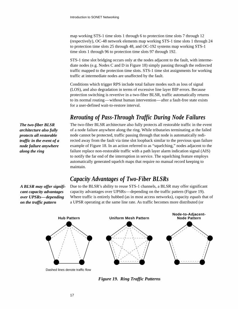
Capacity Advantages of Two-Fiber BLSRsDue to the BLSR’s ability to reuse STS-1 channels, a BLSR may offer significantcapacity advantages over UPSRs—depending on the traffic pattern (Figure 19).Where traffic is entirely hubbed (as in most access networks), capacity equals that ofa UPSR operating at the same line rate. As traffic becomes more distributed (or
The two-fiber BLSRarchitecture also fullyprotects all restorabletraffic in the event of anode failure anywherealong the ring
A BLSR may offer signifi-cant capacity advantagesover UPSRs—dependingon the traffic pattern
Dashed lines denote traffic flow
Hub Pattern Uniform Mesh PatternNode-to-Adjacent-
Node Pattern
Figure 19. Ring Traffic Patterns
18
Introduction to SONET Networking
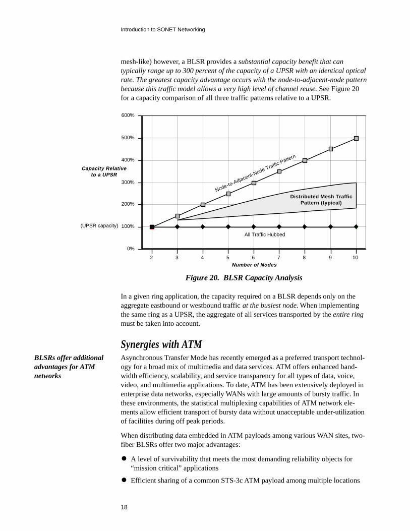
mesh-like) however, a BLSR provides a substantial capacity benefit that cantypically range up to 300 percent of the capacity of a UPSR with an identical opticalrate. The greatest capacity advantage occurs with the node-to-adjacent-node patternbecause this traffic model allows a very high level of channel reuse. See Figure 20for a capacity comparison of all three traffic patterns relative to a UPSR.
2 3 4 5 6 7 8 9 10Number of Nodes
0%
100%
200%
300%
400%
500%
600%
All Traffic Hubbed
Distributed Mesh TrafficPattern (typical)
Node-to-Adjacent-Node TrafficPattern
Capacity Relativeto a UPSR
(UPSR capacity)
Figure 20. BLSR Capacity Analysis
In a given ring application, the capacity required on a BLSR depends only on theaggregate eastbound or westbound traffic at the busiest node. When implementingthe same ring as a UPSR, the aggregate of all services transported by the entire ringmust be taken into account.
Synergies with ATMAsynchronous Transfer Mode has recently emerged as a preferred transport technol-ogy for a broad mix of multimedia and data services. ATM offers enhanced band-width efficiency, scalability, and service transparency for all types of data, voice,video, and multimedia applications. To date, ATM has been extensively deployed inenterprise data networks, especially WANs with large amounts of bursty traffic. Inthese environments, the statistical multiplexing capabilities of ATM network ele-ments allow efficient transport of bursty data without unacceptable under-utilizationof facilities during off peak periods.
When distributing data embedded in ATM payloads among various WAN sites, two-fiber BLSRs offer two major advantages:
• A level of survivability that meets the most demanding reliability objects for“mission critical” applications
• Efficient sharing of a common STS-3c ATM payload among multiple locations
BLSRs offer additionaladvantages for ATMnetworks
19
Introduction to SONET Networking
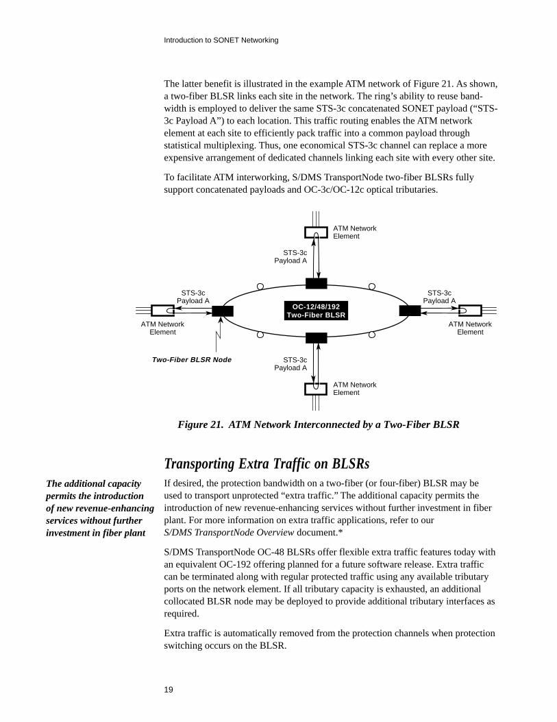
The latter benefit is illustrated in the example ATM network of Figure 21. As shown,a two-fiber BLSR links each site in the network. The ring’s ability to reuse band-width is employed to deliver the same STS-3c concatenated SONET payload (“STS-3c Payload A”) to each location. This traffic routing enables the ATM networkelement at each site to efficiently pack traffic into a common payload throughstatistical multiplexing. Thus, one economical STS-3c channel can replace a moreexpensive arrangement of dedicated channels linking each site with every other site.
To facilitate ATM interworking, S/DMS TransportNode two-fiber BLSRs fullysupport concatenated payloads and OC-3c/OC-12c optical tributaries.
OC-12/48/192Two-Fiber BLSR
Two-Fiber BLSR Node
STS-3cPayload A
ATM NetworkElement
STS-3cPayload A
ATM NetworkElement
STS-3cPayload A
STS-3cPayload A
ATM NetworkElement
ATM NetworkElement
Figure 21. ATM Network Interconnected by a Two-Fiber BLSR
Transporting Extra Traffic on BLSRsIf desired, the protection bandwidth on a two-fiber (or four-fiber) BLSR may beused to transport unprotected “extra traffic.” The additional capacity permits theintroduction of new revenue-enhancing services without further investment in fiberplant. For more information on extra traffic applications, refer to ourS/DMS TransportNode Overview document.*
S/DMS TransportNode OC-48 BLSRs offer flexible extra traffic features today withan equivalent OC-192 offering planned for a future software release. Extra trafficcan be terminated along with regular protected traffic using any available tributaryports on the network element. If all tributary capacity is exhausted, an additionalcollocated BLSR node may be deployed to provide additional tributary interfaces asrequired.
Extra traffic is automatically removed from the protection channels when protectionswitching occurs on the BLSR.
The additional capacitypermits the introductionof new revenue-enhancingservices without furtherinvestment in fiber plant

21
Introduction to SONET Networking
Understanding Four-Fiber BLSRs
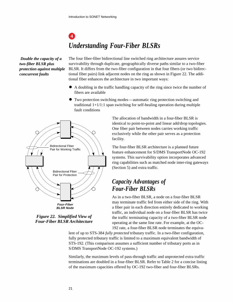
The four fiber-fiber bidirectional line switched ring architecture assures servicesurvivability through duplicate, geographically diverse paths similar to a two-fiberBLSR. It differs from the two-fiber configuration in that four fibers (or two bidirec-tional fiber pairs) link adjacent nodes on the ring as shown in Figure 22. The addi-tional fiber enhances the architecture in two important ways:
• A doubling in the traffic handling capacity of the ring since twice the number offibers are available
• Two protection switching modes—automatic ring protection switching andtraditional 1+1/1:1 span switching for self-healing operation during multiplefault conditions
The allocation of bandwidth in a four-fiber BLSR isidentical to point-to-point and linear add/drop topologies.One fiber pair between nodes carries working trafficexclusively while the other pair serves as a protectionfacility.
The four-fiber BLSR architecture is a planned futurefeature enhancement for S/DMS TransportNode OC-192systems. This survivability option incorporates advancedring capabilities such as matched node inter-ring gateways(Section 5) and extra traffic.
Capacity Advantages ofFour-Fiber BLSRsAs in a two-fiber BLSR, a node on a four-fiber BLSRmay terminate traffic fed from either side of the ring. Witha fiber pair in each direction entirely dedicated to workingtraffic, an individual node on a four-fiber BLSR has twicethe traffic terminating capacity of a two-fiber BLSR nodeoperating at the same line rate. For example, at the OC-192 rate, a four-fiber BLSR node terminates the equiva-
lent of up to STS-384 fully protected tributary traffic. In a two-fiber configuration,fully protected tributary traffic is limited to a maximum equivalent bandwidth ofSTS-192. (This comparison assumes a sufficient number of tributary ports as inS/DMS TransportNode OC-192 systems.)
Similarly, the maximum levels of pass-through traffic and unprotected extra trafficterminations are doubled in a four-fiber BLSR. Refer to Table 2 for a concise listingof the maximum capacities offered by OC-192 two-fiber and four-fiber BLSRs.
Double the capacity of atwo-fiber BLSR plusprotection against multipleconcurrent faults
Bidirectional FiberPair for Working Traffic
Four-FiberBLSR Node
Bidirectional FiberPair for Protection
Figure 22. Simplified View ofFour-Fiber BLSR Architecture
4
22
Introduction to SONET Networking
BLSR TypeMax. Tributary Capacity for
Fully Protected TrafficMax. Pass-Through Traffic
on Working Time Slots
Two Fiber STS-192
Four Fiber
STS-96
Max. Extra TrafficTerminations
STS-192
STS-384 STS-192 STS-384
Table 2. OC-192 Two-Fiber/Four-Fiber BLSR Node Capacity Comparison
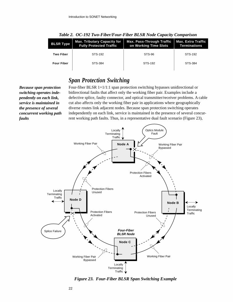
Span Protection SwitchingFour-fiber BLSR 1+1/1:1 span protection switching bypasses unidirectional orbidirectional faults that affect only the working fiber pair. Examples include adefective splice, faulty connector, and optical transmitter/receiver problems. A cablecut also affects only the working fiber pair in applications where geographicallydiverse routes link adjacent nodes. Because span protection switching operatesindependently on each link, service is maintained in the presence of several concur-rent working path faults. Thus, in a representative dual fault scenario (Figure 23),
Node A
Node C
Node B
Working Fiber PairBypassed
Protection FibersActivated
Working Fiber PairBypassed
Protection FibersActivated
Protection FibersUnused
Protection FibersUnused
Working Fiber Pair
Working Fiber Pair
Optics ModuleFault
Splice Failure
Node D
Four-FiberBLSR Node
LocallyTerminating
Traffic
LocallyTerminating
Traffic
LocallyTerminatingTraffic
LocallyTerminating
Traffic
Figure 23. Four-Fiber BLSR Span Switching Example
Because span protectionswitching operates inde-pendently on each link,service is maintained inthe presence of severalconcurrent working pathfaults
23
Introduction to SONET Networking
span protection switching can be activated between Nodes A and B to address anoptics module failure—while at the same time—the protection fibers betweenNodes C and D are in use to bypass a defective splice.
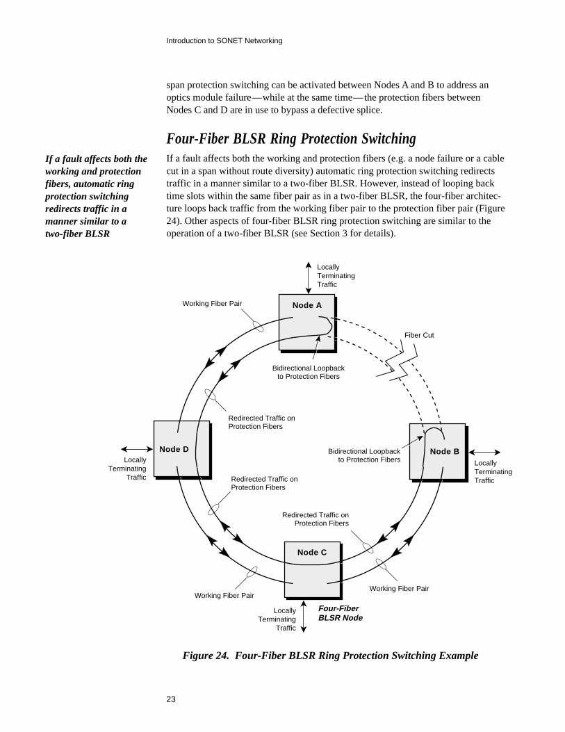
Four-Fiber BLSR Ring Protection SwitchingIf a fault affects both the working and protection fibers (e.g. a node failure or a cablecut in a span without route diversity) automatic ring protection switching redirectstraffic in a manner similar to a two-fiber BLSR. However, instead of looping backtime slots within the same fiber pair as in a two-fiber BLSR, the four-fiber architec-ture loops back traffic from the working fiber pair to the protection fiber pair (Figure24). Other aspects of four-fiber BLSR ring protection switching are similar to theoperation of a two-fiber BLSR (see Section 3 for details).
Figure 24. Four-Fiber BLSR Ring Protection Switching Example
Node A
Node C
Node B
Redirected Traffic onProtection Fibers
Working Fiber Pair
Working Fiber Pair
Node D
Four-FiberBLSR Node
Bidirectional Loopbackto Protection Fibers
Bidirectional Loopbackto Protection Fibers
Fiber Cut
Working Fiber Pair
Redirected Traffic onProtection Fibers
Redirected Traffic onProtection Fibers
LocallyTerminatingTraffic
LocallyTerminating
Traffic
LocallyTerminating
Traffic
LocallyTerminatingTraffic
If a fault affects both theworking and protectionfibers, automatic ringprotection switchingredirects traffic in amanner similar to atwo-fiber BLSR

25
Introduction to SONET Networking
Understanding Matched Nodes
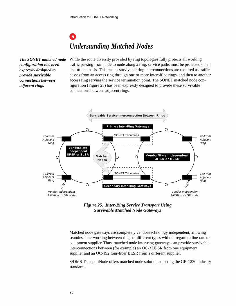
While the route diversity provided by ring topologies fully protects all workingtraffic passing from node to node along a ring, service paths must be protected on anend-to-end basis. This means survivable ring interconnections are required as trafficpasses from an access ring through one or more interoffice rings, and then to anotheraccess ring serving the service termination point. The SONET matched node con-figuration (Figure 25) has been expressly designed to provide these survivableconnections between adjacent rings.
Vendor/RateIndependent
UPSR or BLSR
Primary Inter-Ring Gateways
Secondary Inter-Ring Gateways
Vendor-IndependentUPSR or BLSR node
To/FromAdjacent
Ring
To/FromAdjacent
Ring
Survivable Service Interconnection Between Rings
Vendor/Rate IndependentUPSR or BLSR
MatchedNodes
To/FromAdjacentRing
To/FromAdjacentRing
SONET Tributaries
SONET Tributaries
Vendor-IndependentUPSR or BLSR node
Figure 25. Inter-Ring Service Transport UsingSurvivable Matched Node Gateways
Matched node gateways are completely vendor/technology independent, allowingseamless interworking between rings of different types without regard to line rate orequipment supplier. Thus, matched node inter-ring gateways can provide survivableinterconnections between (for example) an OC-3 UPSR from one equipmentsupplier and an OC-192 four-fiber BLSR from a different supplier.
S/DMS TransportNode offers matched node solutions meeting the GR-1230 industrystandard.
The SONET matched nodeconfiguration has beenexpressly designed toprovide survivableconnections betweenadjacent rings
5
26
Introduction to SONET Networking
D&C SS
Drop & ContinueRouting for
Outbound Signal
Service Selector switchesto secondary input if
primary link fails
STS-1,OC-3, OC/
STS-12
D&C SS
Primary Inter-Ring Gateways
Secondary Inter-Ring Gateways
Inter-Ring Service “A” Inter-Ring Service “A”
Inter-Ring Service “A”
Inter-RingService “A”
Vendor-IndependentBLSR Node
Vendor-Independent BLSR
Fiber Span
Vendor-Independent BLSR
Fiber Span
Failed
Vendor-IndependentBLSR Node
Vendor-IndependentBLSR Nodes
D&C = Drop & Continue RoutingSS = Service Selector
Figure 26. Duplicate Inter-Ring Service Paths Provided byMatched Node Gateways, BLSR Example Shown
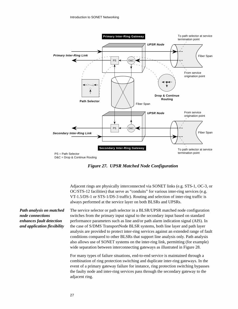
UPSR matched node configurations employ standard UPSR path selection tech-niques plus drop-and-continue routing as shown in Figure 27. From the point ofview of an adjacent ring, this arrangement functions in exactly the same manner asBLSR matched node inter-ring gateways.
A network element provisioned as a primary gateway for one inter-ring service maybe provisioned as a secondary gateway (or neither) for another inter-ring service—as needed for most efficient use of the ring’s available bandwidth. Also, a primarygateway on one ring may feed either a primary or secondary gateway on an adjacentring as desired.
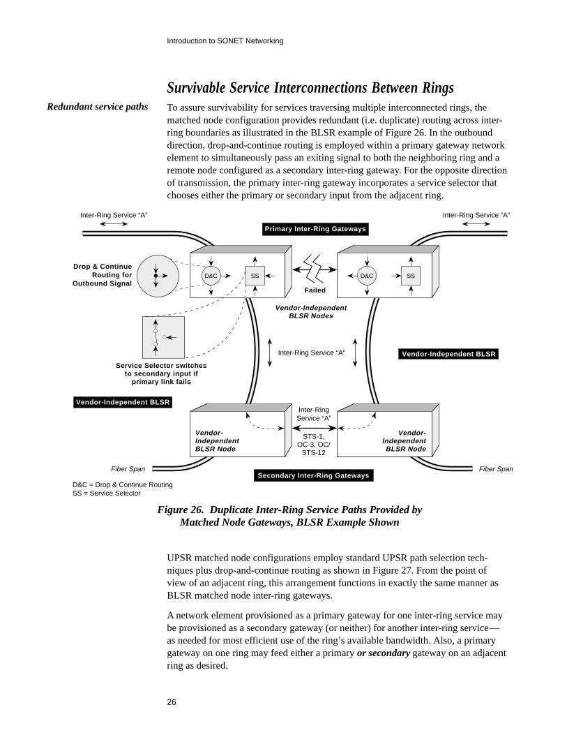
Redundant service paths
Survivable Service Interconnections Between RingsTo assure survivability for services traversing multiple interconnected rings, thematched node configuration provides redundant (i.e. duplicate) routing across inter-ring boundaries as illustrated in the BLSR example of Figure 26. In the outbounddirection, drop-and-continue routing is employed within a primary gateway networkelement to simultaneously pass an exiting signal to both the neighboring ring and aremote node configured as a secondary inter-ring gateway. For the opposite directionof transmission, the primary inter-ring gateway incorporates a service selector thatchooses either the primary or secondary input from the adjacent ring.
27
Introduction to SONET Networking
Figure 27. UPSR Matched Node Configuration
Adjacent rings are physically interconnected via SONET links (e.g. STS-1, OC-3, orOC/STS-12 facilities) that serve as “conduits” for various inter-ring services (e.g.VT-1.5/DS-1 or STS-1/DS-3 traffic). Routing and selection of inter-ring traffic isalways performed at the service layer on both BLSRs and UPSRs.
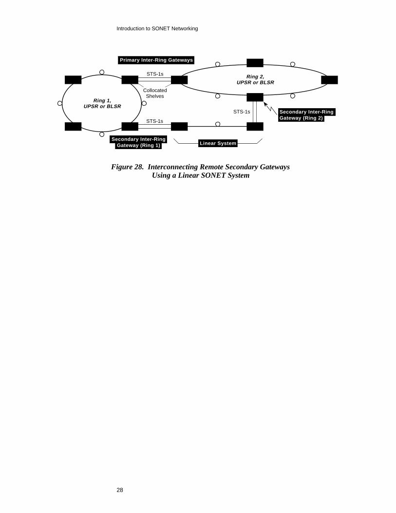
The service selector or path selector in a BLSR/UPSR matched node configurationswitches from the primary input signal to the secondary input based on standardperformance parameters such as line and/or path alarm indication signal (AIS). Inthe case of S/DMS TransportNode BLSR systems, both line layer and path layeranalysis are provided to protect inter-ring services against an extended range of faultconditions compared to other BLSRs that support line analysis only. Path analysisalso allows use of SONET systems on the inter-ring link, permitting (for example)wide separation between interconnecting gateways as illustrated in Figure 28.
For many types of failure situations, end-to-end service is maintained through acombination of ring protection switching and duplicate inter-ring gateways. In theevent of a primary gateway failure for instance, ring protection switching bypassesthe faulty node and inter-ring services pass through the secondary gateway to theadjacent ring.
Path analysis on matchednode connectionsenhances fault detectionand application flexibility
PS
D&CPS
D&C
Primary Inter-Ring Gateway
Secondary Inter-Ring Gateway
Primary Inter-Ring Link
Secondary Inter-Ring Link
Drop & ContinueRouting
Path SelectorFiber Span
Fiber Span
UPSR Node
UPSR Node
PS = Path SelectorD&C = Drop & Continue Routing
To path selector at servicetermination point
From serviceorigination point
To path selector at servicetermination point
From serviceorigination point
Fiber Span
28
Introduction to SONET Networking
Figure 28. Interconnecting Remote Secondary GatewaysUsing a Linear SONET System
Secondary Inter-RingGateway (Ring 2)
STS-1s
STS-1s
STS-1s
Primary Inter-Ring Gateways
Ring 1,UPSR or BLSR
Ring 2
Linear System
CollocatedShelves
Ring 2,UPSR or BLSR
Secondary Inter-RingGateway (Ring 1)
29
Introduction to SONET Networking
Wave Division Multiplexing
WDM multiplies (up to eight times) the capacity of existing fiber spans by combin-ing two or more optical signals of different wavelengths on a single fiber. Because itdefers—or avoids altogether—the large capital outlays and long lead times associ-ated with deploying new fiber cable, wave division multiplexing is an ideal solutionfor critical high-growth routes having an immediate need for more bandwidth.
An external coupling device performs the actual mixing of the different opticalsignals. In unidirectional WDM, multiple wavelengths travel in the same directionon an optical fiber while they pass in opposite directions in bidirectional WDMarrangements. Bidirectional WDM is often the preferred approach, especially inapplications employing two wavelengths due to the one-to-one association of anindividual transport system to an individual optical fiber.
WDM can be further classified as either wideband (also called crossband),narrowband, or dense depending on the wavelengths involved. TheS/DMS TransportNode family supports all three types on bidirectional optical fiber.
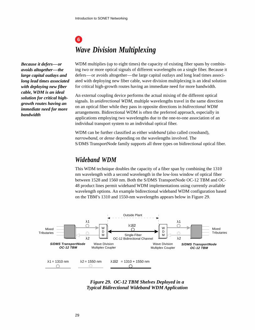
Wideband WDMThis WDM technique doubles the capacity of a fiber span by combining the 1310nm wavelength with a second wavelength in the low-loss window of optical fiberbetween 1528 and 1560 nm. Both the S/DMS TransportNode OC-12 TBM and OC-48 product lines permit wideband WDM implementations using currently availablewavelength options. An example bidirectional wideband WDM configuration basedon the TBM’s 1310 and 1550-nm wavelengths appears below in Figure 29.
WDM
λ1+λ2λ1
λ2
λ1
λ2Single-Fiber
OC-12 Bidirectional Channel
λ1 = 1310 nm
S/DMS TransportNode OC-12 TBM
Wave DivisionMultiplex Coupler
MixedTributaries
MixedTributaries
Wave DivisionMultiplex Coupler
Outside Plant
WDM
λ2 = 1550 nm λ1+λ2 = 1310 + 1550 nm
S/DMS TransportNodeOC-12 TBM
Figure 29. OC-12 TBM Shelves Deployed in aTypical Bidirectional Wideband WDM Application
Because it defers—oravoids altogether—thelarge capital outlays andlong lead times associatedwith deploying new fibercable, WDM is an idealsolution for critical high-growth routes having animmediate need for morebandwidth
6
30
Introduction to SONET Networking
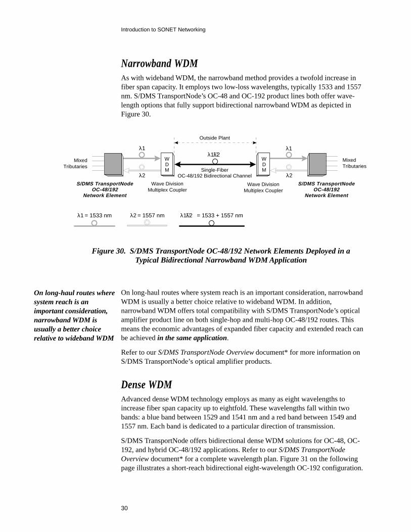
Narrowband WDMAs with wideband WDM, the narrowband method provides a twofold increase infiber span capacity. It employs two low-loss wavelengths, typically 1533 and 1557nm. S/DMS TransportNode’s OC-48 and OC-192 product lines both offer wave-length options that fully support bidirectional narrowband WDM as depicted inFigure 30.
WDM
λ1+λ2λ1
λ2
λ1
λ2Single-Fiber
OC-48/192 Bidirectional Channel
λ1 = 1533 nm
S/DMS TransportNodeOC-48/192
Network Element
Wave DivisionMultiplex Coupler
MixedTributaries
MixedTributaries
S/DMS TransportNodeOC-48/192
Network Element
Wave DivisionMultiplex Coupler
Outside Plant
WDM
λ2 = 1557 nm λ1+λ2 = 1533 + 1557 nm
Figure 30. S/DMS TransportNode OC-48/192 Network Elements Deployed in aTypical Bidirectional Narrowband WDM Application
On long-haul routes wheresystem reach is animportant consideration,narrowband WDM isusually a better choicerelative to wideband WDM
On long-haul routes where system reach is an important consideration, narrowbandWDM is usually a better choice relative to wideband WDM. In addition,narrowband WDM offers total compatibility with S/DMS TransportNode’s opticalamplifier product line on both single-hop and multi-hop OC-48/192 routes. Thismeans the economic advantages of expanded fiber capacity and extended reach canbe achieved in the same application.
Refer to our S/DMS TransportNode Overview document* for more information onS/DMS TransportNode’s optical amplifier products.
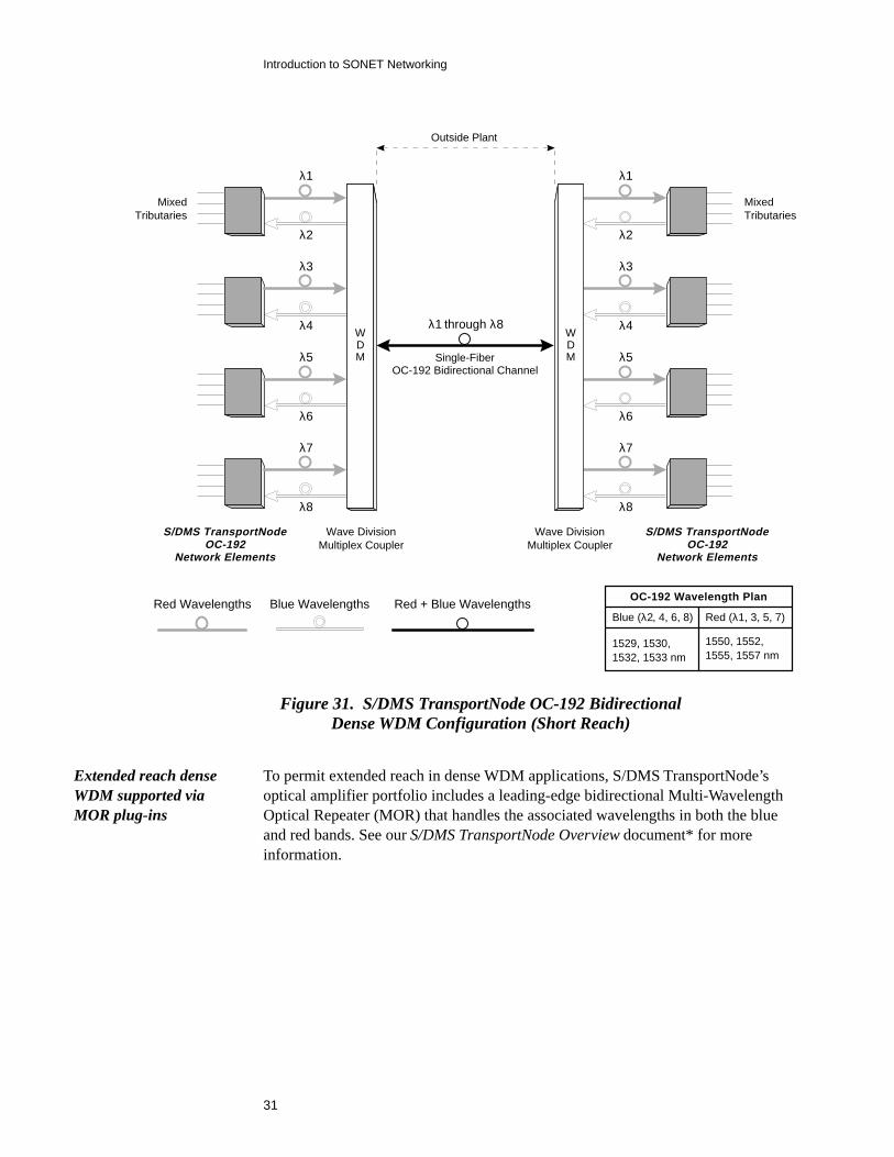
Dense WDMAdvanced dense WDM technology employs as many as eight wavelengths toincrease fiber span capacity up to eightfold. These wavelengths fall within twobands: a blue band between 1529 and 1541 nm and a red band between 1549 and1557 nm. Each band is dedicated to a particular direction of transmission.
S/DMS TransportNode offers bidirectional dense WDM solutions for OC-48, OC-192, and hybrid OC-48/192 applications. Refer to our S/DMS TransportNodeOverview document* for a complete wavelength plan. Figure 31 on the followingpage illustrates a short-reach bidirectional eight-wavelength OC-192 configuration.
31
Introduction to SONET Networking
To permit extended reach in dense WDM applications, S/DMS TransportNode’soptical amplifier portfolio includes a leading-edge bidirectional Multi-WavelengthOptical Repeater (MOR) that handles the associated wavelengths in both the blueand red bands. See our S/DMS TransportNode Overview document* for moreinformation.
λ1
λ2
MixedTributaries
λ3
λ4
λ5
λ6
λ7
λ8
WDM
λ1
λ2
MixedTributaries
λ3
λ4
λ5
λ6
λ7
λ8
WDM
λ1 through λ8
Single-FiberOC-192 Bidirectional Channel
Red Wavelengths
S/DMS TransportNodeOC-192
Network Elements
Wave DivisionMultiplex Coupler
S/DMS TransportNodeOC-192
Network Elements
Wave DivisionMultiplex Coupler
Outside Plant
Blue Wavelengths Red + Blue WavelengthsOC-192 Wavelength Plan
Red (λ1, 3, 5, 7)Blue (λ2, 4, 6, 8)
1529, 1530,1532, 1533 nm
1550, 1552,1555, 1557 nm
Figure 31. S/DMS TransportNode OC-192 BidirectionalDense WDM Configuration (Short Reach)
Extended reach denseWDM supported viaMOR plug-ins

33
Introduction to SONET Networking
Using SONET Rings to Manage Bandwidthin Small-City Networks
Efficient management of DS-1 traffic is a critically important function in just aboutevery interoffice network since most services are transported in the VT/DS-1 layer.Effective solutions for traffic routing, grooming, consolidation, and the like must beput in place to avoid escalating operational costs, congestion, and a premature needfor network expansion.
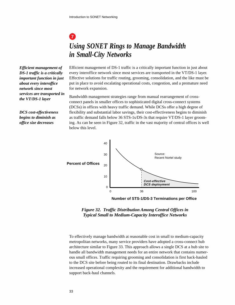
Bandwidth management strategies range from manual rearrangement of cross-connect panels in smaller offices to sophisticated digital cross-connect systems(DCSs) in offices with heavy traffic demand. While DCSs offer a high degree offlexibility and substantial labor savings, their cost-effectiveness begins to diminishas traffic demand falls below 36 STS-1s/DS-3s that require VT/DS-1 layer groom-ing. As can be seen in Figure 32, traffic in the vast majority of central offices is wellbelow this level.
Figure 32. Traffic Distribution Among Central Offices inTypical Small to Medium-Capacity Interoffice Networks
Efficient management ofDS-1 traffic is a criticallyimportant function in justabout every interofficenetwork since mostservices are transported inthe VT/DS-1 layer
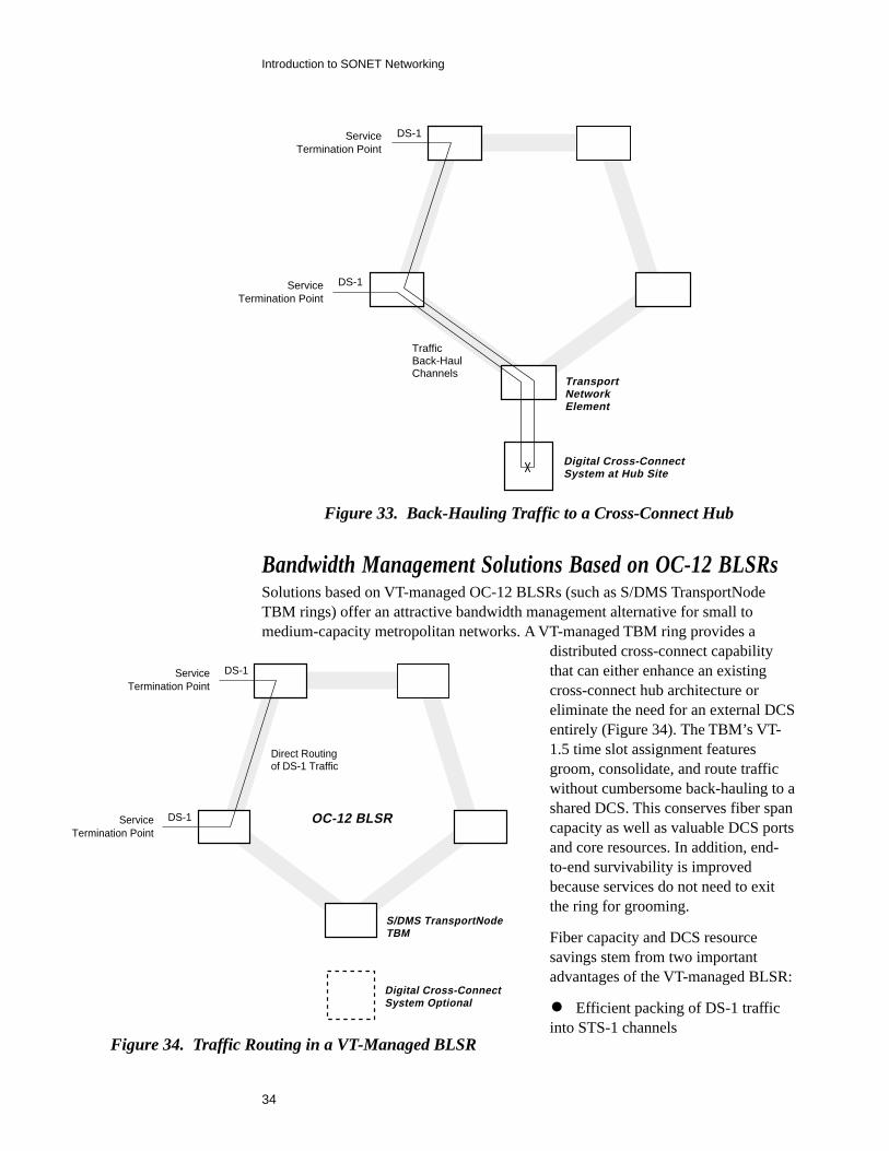
To effectively manage bandwidth at reasonable cost in small to medium-capacitymetropolitan networks, many service providers have adopted a cross-connect hubarchitecture similar to Figure 33. This approach allows a single DCS at a hub site tohandle all bandwidth management needs for an entire network that contains numer-ous small offices. Traffic requiring grooming and consolidation is first back-hauledto the DCS site before being routed to its final destination. Drawbacks includeincreased operational complexity and the requirement for additional bandwidth tosupport back-haul channels.
DCS cost-effectivenessbegins to diminish asoffice size decreases
Number of STS-1/DS-3 Terminations per Office
0
10
20
30
40
Percent of Offices
100
Source:Recent Nortel study
0
Cost-effectiveDCS deployment
36
7
34
Introduction to SONET Networking
Figure 33. Back-Hauling Traffic to a Cross-Connect Hub
DS-1
DS-1
ServiceTermination Point
ServiceTermination Point
Digital Cross-ConnectSystem at Hub Site
TransportNetworkElement
TrafficBack-HaulChannels
Bandwidth Management Solutions Based on OC-12 BLSRsSolutions based on VT-managed OC-12 BLSRs (such as S/DMS TransportNodeTBM rings) offer an attractive bandwidth management alternative for small tomedium-capacity metropolitan networks. A VT-managed TBM ring provides a
distributed cross-connect capabilitythat can either enhance an existingcross-connect hub architecture oreliminate the need for an external DCSentirely (Figure 34). The TBM’s VT-1.5 time slot assignment featuresgroom, consolidate, and route trafficwithout cumbersome back-hauling to ashared DCS. This conserves fiber spancapacity as well as valuable DCS portsand core resources. In addition, end-to-end survivability is improvedbecause services do not need to exitthe ring for grooming.
Fiber capacity and DCS resourcesavings stem from two importantadvantages of the VT-managed BLSR:
• Efficient packing of DS-1 trafficinto STS-1 channels
DS-1
DS-1
ServiceTermination Point
ServiceTermination Point
Digital Cross-ConnectSystem Optional
S/DMS TransportNodeTBM
Direct Routingof DS-1 Traffic
OC-12 BLSR
Figure 34. Traffic Routing in a VT-Managed BLSR
35
Introduction to SONET Networking
• Fewer services back-hauled to a hub site for grooming
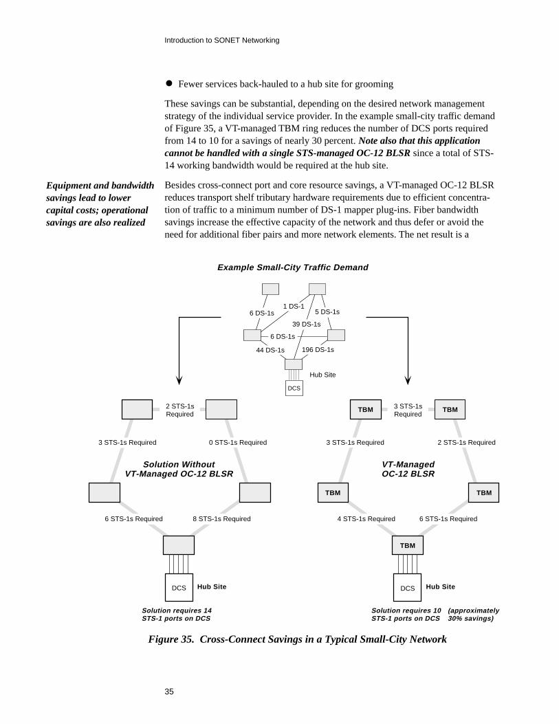
These savings can be substantial, depending on the desired network managementstrategy of the individual service provider. In the example small-city traffic demandof Figure 35, a VT-managed TBM ring reduces the number of DCS ports requiredfrom 14 to 10 for a savings of nearly 30 percent. Note also that this applicationcannot be handled with a single STS-managed OC-12 BLSR since a total of STS-14 working bandwidth would be required at the hub site.
Besides cross-connect port and core resource savings, a VT-managed OC-12 BLSRreduces transport shelf tributary hardware requirements due to efficient concentra-tion of traffic to a minimum number of DS-1 mapper plug-ins. Fiber bandwidthsavings increase the effective capacity of the network and thus defer or avoid theneed for additional fiber pairs and more network elements. The net result is a
1 DS-1
Hub Site
Solution WithoutVT-Managed OC-12 BLSR
Example Small-City Traffic Demand
2 STS-1sRequired
DCS Hub Site
Solution requires 14STS-1 ports on DCS
DCS
VT-ManagedOC-12 BLSR
TBM
TBM TBM
TBM
TBM
DCS
Solution requires 10STS-1 ports on DCS
Hub Site
3 STS-1sRequired
(approximately30% savings)
6 DS-1s
44 DS-1s 196 DS-1s
6 DS-1s
39 DS-1s
5 DS-1s
3 STS-1s Required
6 STS-1s Required 8 STS-1s Required
0 STS-1s Required 3 STS-1s Required 2 STS-1s Required
4 STS-1s Required 6 STS-1s Required
Figure 35. Cross-Connect Savings in a Typical Small-City Network
Equipment and bandwidthsavings lead to lowercapital costs; operationalsavings are also realized
36
Introduction to SONET Networking
substantial reduction in capital costs in the typical small-city network. Also, opera-tional costs (and labor) are reduced as well because fewer back-hauled servicesmean less management complexity.
Our VTBM 101 handbook, document number 56135.11, provides an in-depthanalysis of the many applications, implementation strategies, economic advantages,and other benefits associated with VT-managed bidirectional line switched rings. Ifyou would like to further explore this important SONET networking technology, justvisit our Broadband Networks home page (http://www.nortel.com/broadband) anddownload the VTBM 101 document—or call 1-800-4 NORTEL (1-800-466-7835)and ask a Nortel representative to send you a paper copy.
37
Introduction to SONET Networking
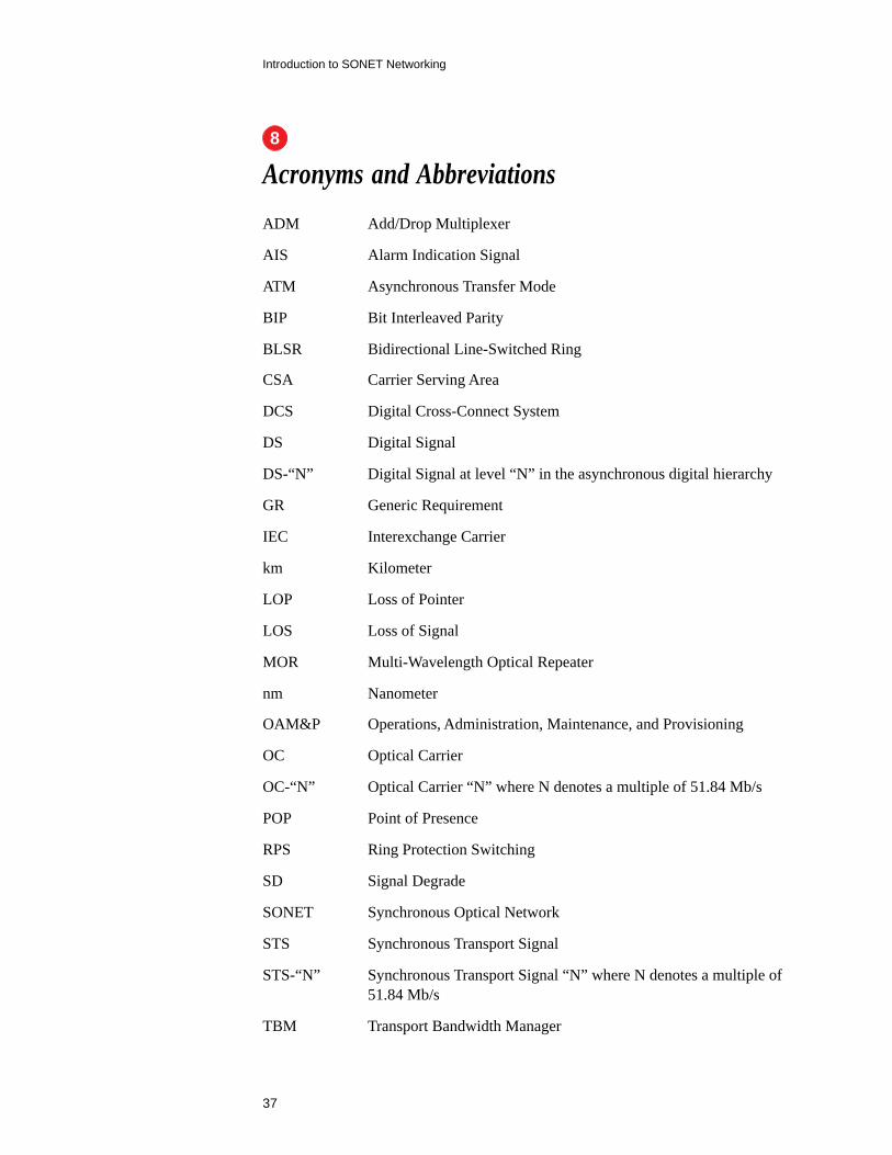
Acronyms and Abbreviations
ADM Add/Drop Multiplexer
AIS Alarm Indication Signal
ATM Asynchronous Transfer Mode
BIP Bit Interleaved Parity
BLSR Bidirectional Line-Switched Ring
CSA Carrier Serving Area
DCS Digital Cross-Connect System
DS Digital Signal
DS-“N” Digital Signal at level “N” in the asynchronous digital hierarchy
GR Generic Requirement
IEC Interexchange Carrier
km Kilometer
LOP Loss of Pointer
LOS Loss of Signal
MOR Multi-Wavelength Optical Repeater
nm Nanometer
OAM&P Operations, Administration, Maintenance, and Provisioning
OC Optical Carrier
OC-“N” Optical Carrier “N” where N denotes a multiple of 51.84 Mb/s
POP Point of Presence
RPS Ring Protection Switching
SD Signal Degrade
SONET Synchronous Optical Network
STS Synchronous Transport Signal
STS-“N” Synchronous Transport Signal “N” where N denotes a multiple of51.84 Mb/s
TBM Transport Bandwidth Manager
8
38
Introduction to SONET Networking
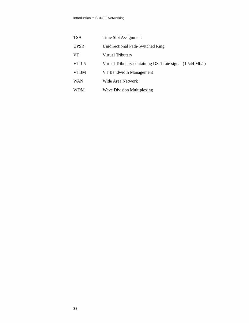
TSA Time Slot Assignment
UPSR Unidirectional Path-Switched Ring
VT Virtual Tributary
VT-1.5 Virtual Tributary containing DS-1 rate signal (1.544 Mb/s)
VTBM VT Bandwidth Management
WAN Wide Area Network
WDM Wave Division Multiplexing

Nortel, the Nortel globe mark, OC-3 Express, S/DMS, S/DMSTransportNode are trademarks of Northern Telecom.
All other trademarks are the property of their respective holders.
Information subject to change, since Northern Telecom reservesthe right to make changes, without notice, in equipment design orcomponents as progress in engineering or manufacturing methodsmay warrant. Product capabilities and availability dates describedin this document pertain solely to Northern Telecom’s marketingactivities in the United States and Canada. Availability in othermarkets may vary.
For more information, contact your Nortel representative or call1-800-4 NORTEL (1-800-466-7835) or 972-684-5930.
Northern TelecomDepartment 96045555 Windward Parkway, Suite BAlpharetta, GA 30201-3895
Northern Telecom Canada LimitedDepartment X3809300 Trans Canada HighwaySt. Laurent, Quebec H4S 1K5
Published by Northern TelecomOctober 1996
To comment on this document, send E-mail to:[email protected] can obtain an electronic copy of this document by visiting ourBroadband Networks home page at:http://www.nortel.com/broadband