Embed Size (px)
Citation preview

B1
Intrinsic Safety Exi:Origins
PrinciplesApparatus
Applications
Intrinsic safety
Gary Friend
Sales Director
B2Explosions
B3
Mine Signalling Systemcirca 1910
BREAK FLASH
BARE WIRES
BELLBATTERY
WINCH OPERATOR
Origins of Intrinsic Safety B4
Hazardouslocation
Air(Oxygen)Gas
Source ofIgnition
SparkHeat
Fire triangle
B5
1. Limit Current
2. Limit Voltage
3. Limit Stored Electrical Energy
Three Principles of Ex i Design B6
Open Circuit Voltage
ShortCircuitCurrent
VOC
ISC
Output characteristic
of simple resistivesource
I
Ignitionoccurs
Energy
Power
Ignitionoccurs
VIs/c
R
Ignition does not
occur
The Load line
LIMITEDPOWER
LIMITED
ENERGY
Voltage and Current Characteristics
B7
HazardousArea
Apparatus
UncertifiedSafe AreaApparatus
Hazardous Area Safe Area
CertifiedSafe AreaApparatus
HazardousArea
Apparatus
CertifiedInterface
Intrinsically safe systems B8
A system, comprising apparatus and interconnecting wiring, in which any spark or thermal effect in any part of the system intended for use in hazardous areas is incapable of causing ignition.
Intrinsically Safe System
Definition
B9
Probability of
Gas/Air Mixture
being present
Probability of
Source of
Ignition
X =Acceptable
Risk
Reasoning: Higher probability of the gas/air mixture being present requires a lower probability of having a source of ignition and vice versa.
Hence, different Ex protection types are only permitted in specific levels of risk owing to their level of reliability.
Why Area Classify? B10
Hazardous places are classified in terms of zones on the basis of the frequency & duration of the occurrence of an explosive atmosphere
Zone 0 : an explosive atmosphere in the form of gas, vapour, or mist is present continuously, for long periods or frequently
Zone 1 : an explosive atmosphere in the form of gas, vapour, or mist is likely to occur in normal operation occasionally
Zone 2 : an explosive atmosphere in the form of gas, vapour, or mist is not likely to occur in normal operation, but if it does occur, will persist for a short period only
Area Classification - gas, vapour & mist
B11
Liquid
surface
Zone 0
Zone 1
Zone 2
typically 3m from
vent openings
typically 3m above the roof
typically 3m
horizontally
from tank
sump
Area Classification Example
Bund wall
B12
"Faults" are those in componentsupon which safety of the
installation depends.
Ex iaIntrinsically safe
with two faults
Zones 0, 1 and 2
Intrinsic safety levels of protection
Ex ibIntrinsically safe
with one fault
Ex icIntrinsically safe
in normal operation
Zone 2
Zones 1 and 2
Note.Intrinsic safety is the only protection concept that considers failure of the
field wiring.
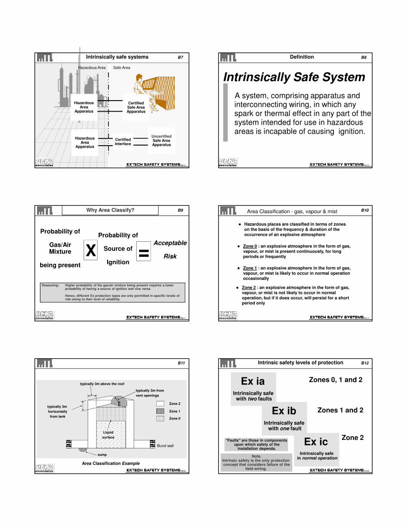
B13Gas Group / T rating B14
Hazardous Area Apparatus:
Certified: Complex energy-storinge.g instruments
or
Uncertified: "Simple Apparatus"
SafetyCertificate
SANS/IEC 60079-11
Clause 5.7
Hazardous Area “Apparatus”
B15
Examples:
Simple Apparatus
What is considered Simple Apparatus?
Passive components e.g. switches, junction boxes, potentiometers and simple semiconductor devices
Sources of stored energy within well defined parameters
Sources of generated energy which do not exceed 1.5V, 0.1A or 25mW
IEC 60079-11, Clause 5.7 says:-
“Devices need not be certified or marked”
B16Combustible dusts and powders
B17
Zone 20 : an explosive atmosphere in the form of a cloud of combustible dust in air is present continuously, for long periods or frequently
Zone 21 : an explosive atmosphere in the form of a cloud of combustible dust in air is likely to occur in normal operation occasionally
Zone 22 : an explosive atmosphere in the form of a cloud of combustible dust in air is not likely to occur in normal operation, but if it does occur, will persist for a short period only
Notes: Layers,deposits and heaps of combustibledust must be considered as a source that can form
an explosive atmosphere
Area Classification - Dusts B18
Area classification of dusts and powders must be treated differently from gases and vapours:
Dusts don’t disperse with time
Ventilation can convert layers into clouds
Other considerations
Resistivity - low resistivity powders e.g. metals are more hazardous and require additional measures to be applied to equipmentCloud concentration, particle size, moistureLayer thickness
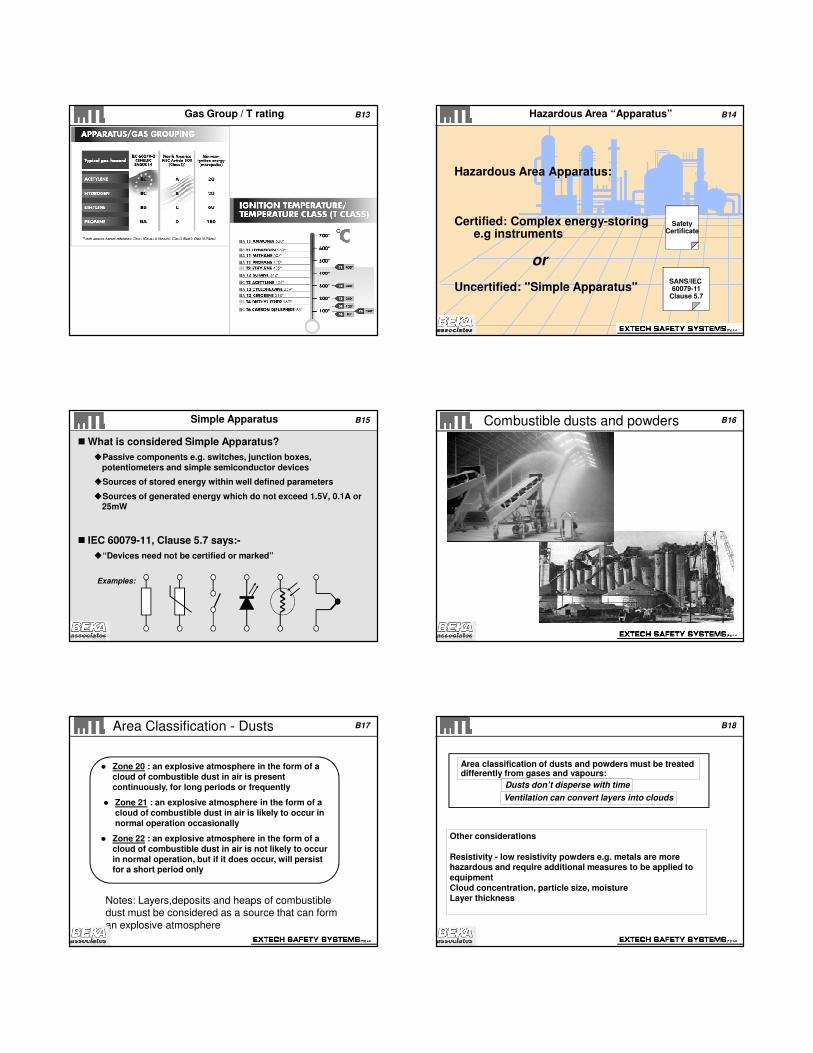
B19
Dust flammability
About 70% of dusts occurring in industry are flammable
Ignition energy
Dusts and powders typically require higher spark energy levels for
ignition (1000 times greater than vapours)More likely mechanism is hot surface ignition
Ignition temperatureWhereas the majority of flammable gases have ignition temperatures
above 350°C, some dusts ignite at 150 - 200°C
Ingress protection alone is not enough
Ingress protection alone for equipment is not enough: must protect against ignition by raised temperatures of enclosures
Combustible dusts and powders B20
Intrinsic SafetyInterfaces:
BASIC PRINCIPLES of
Barriers & Isolators
Intrinsic SafetyInterfaces:
BASIC PRINCIPLES of
Barriers & Isolators
Safe Area
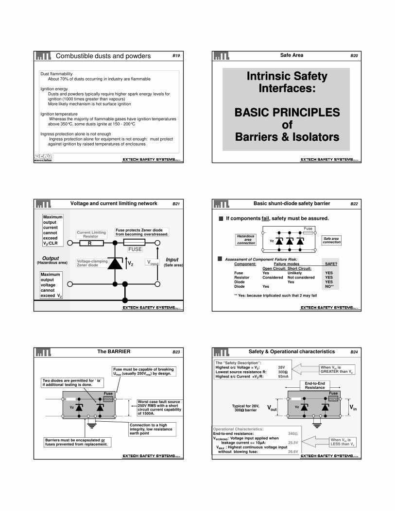
B21
Output Input
Maximum
output
current
cannot
exceed
VZ/CLR
(Hazardous area)(Safe area)
Vinput
Maximum
output
voltage
cannot
exceed VZ
FUSE
Fuse protects Zener diodefrom becoming overstressed.Current Limiting
Resistor
R
Voltage-clampingZener diode VZ
Voltage and current limiting network B22
Vz
Assessment of Component Failure Risk:
Component: Failure modes SAFE?
Open Circuit: Short Circuit:
Fuse Yes Unlikely YES
Resistor Considered Not considered YES
Diode Yes YES
Diode Yes NO**
** Yes: because triplicated such that 2 may fail
Fuse
Safe area connection
Hazardous area
connection
If components fail, safety must be assured.
Basic shunt-diode safety barrier
B23
Barriers must be encapsulated orfuses prevented from replacement.
Connection to a high integrity, low resistance earth point
Fuse must be capable of breakingUmax (usually 250Vrms) by design.
Two diodes are permitted for ‘ ia’if additional testing is done.
Vz
Fuse
Worst case fault source250V RMS with a shortcircuit current capabilityof 1500A.
The BARRIER B24
Typical for 28V, 300ΩΩΩΩ barrier
The “Safety Description”:
Highest o/c Voltage = VZ: 28V
Lowest source resistance R: 300ΩΩΩΩ
Highest s/c Current =VZ/R: 93mA
When Vin is GREATER than Vz
End-to-End Resistance
When Vin isLESS than Vz
Operational Characteristics:
End-to-end resistance: 340ΩΩΩΩ
VWORKING: Voltage input applied when
leakage current =< 10µA: 25.5V
VMAX : Highest continuous voltage input
without blowing fuse: 26.6V
Vout VinVz
Fuse
Safety & Operational characteristics
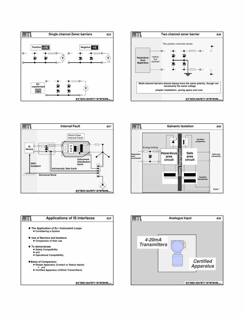
B25
Positive Negative
ACunpolarised
+VE -VE
~
V+
-V
+
-
V
Single channel Zener barriers B26
Multi-channel barriers almost always have the same polarity, though not necessarily the same voltage
simpler installation, saving space and cost
HazardousArea
Apparatus
neitherline
earthed
Two positive channels shown
Two channel zener barrier
B27
PSU
ELECT.
ISDevice
Structural Bond
Intrinsically Safe Earth
Instrument DistributionEarth500V
Isolation!
Worst CaseInternal Fault!
Internal Fault B28
Certifiedtransformer
Certifiedcomponent
Energy-limiting
Safe areaconnection
Hazardousareaconnection
Power
Safe
ty S
eg
reg
ati
on
Safearea
circuit
Hazardousarea
circuit
Galvanic Isolation
B29Applications of IS interfaces
The Application of Ex i Instrument Loops Considering a System
Use of Barriers and Isolators Comparison of their use
To demonstrate Safety Compatibility
and
Operational Compatibility
Basis of Comparison Simple Apparatus (Contact or Status Inputs)
and
Certified Apparatus (4/20mA Transmitters)
B30
4-20mATransmitters
CertifiedApparatus
Analogue Input

B31Transmitter parameters
SAFETY What does the Certificate state?
Certification codeeg EEx ia IIC T4Transmitter "entity" parameters typically are quoted e.g. Ui < 30V Ii < 100 mA Pi < 1.3 W Li < 10µH Ci < 20nF Must be MATCHED to Interface…… follows
OPERATION Will it work?
Transmitters require Minimum “Lift-off” supply voltage (order of 12V at 20 mA) Load (conditioning) resistor; Most safe area equipment uses 250ΩΩΩΩ
Passage of SMART Communications (HART, etc)
B32
CC < 0.063 µF
LC < 4.20 mH
L/RC < 55 µH/ΩΩΩΩ
System
EEx ia IIC T4
Cable Parameters
Verification of safety compatibility
Transmitter
EEx ia IIC T4
Ui < 30 VIi < 100 mAPi < 1.3W
Ci < 20 nFLi < 10µH
[EEx ia] IIC
For MTL7787+Cable parameters are quoted forIIC unless otherwise stated
Interface
Uo < 28 VIo < 93 mAPo < 0.65 W
Co < 0.083 µFLo < 4.2 mHL/R < 55 µH/ΩΩΩΩ
MTL7728+
B33Transmitters with 2-channel barriers
Many systems use bulk power supplies Signals often referenced to a common 0V connection
One-channel barriers cannot be used with bulk supplies
2-channel barriers are necessarySO....…
The combination of two channels has to be shown to be safe in the particular hazard intended:
Two-channel barriers are normally certified as one unit
B34
333ΩΩΩΩ max
Hazardous area Safe area
IS Earth
4-20 mA
24V+
0 Volts
250ΩΩΩΩConditioningresistor
1-5V
Tx: Diode Return Barrier (MTL7787+)
B35Operational compatibility (MTL7787+)
Loop voltage drops at 20mA are:
Barrier (6.7+0.5+0.9) = 8.1 Transmitter = 12.0Instrument = 5.0
Total = 25.1V
Nom. working voltage = 26.6 V (for 10µA leakage)
Overall loop supply limits:-High Limit:- 25.1 to 26.6V OK to use 26.6V max because
leakage in the outgoing leg does not go through the loadLow Limit:- Transmitter will not calibrate at Full Scale!And .. Communications lost when tx saturates!
Leakage on the return leg is insignificant: 7.2V max at 20mA
B36Diode return barrier for 2-wire Tx
Two channel barrier permits “common-ed” power supply (-ve) and input
circuits
3 Schottky diodes have about 0.9 V forward volt-drop, so overall return channel
drop at 20mA is 1.4V
Return channel blocking diodes prevent fault current into the hazardous area The Safety Description is the same as for a 28V 300R 93mA barrier
The return channel 28V rating removes its vulnerability to being damaged by
accidental connection reversal (an advantage over earlier two-channel types,
such as MTL 788)
Loop supply voltage range is 25.1 to 26.6 volts for 12 volts transmitter and lines Supply below Loop Minimum will prevent transmitter operation at full-scale!
Supply channel leakage for above 26.6V (VWORKING) does not add inaccuracy to
loop Care with operation above 27.2 (VMAX) will stress fuse and cause premature failure

B37
Load(600ΩΩΩΩ)
4-20 mA 16.5V
300ΩΩΩΩ
28V
Isolation
Hazardous area Safe area
Isolator for 2-wire transmitters
24VdcSupply
4-20 mAPowered fromHazardousArea
Non-Energy Storing
Input Terminals
HHC
B38Isolator specification
Things to remember Choosing an Isolator
Isolators are designed to suit a particular applicationCheck compatibility for SafetyCheck compatibility for Operation
Other IssuesRequires power supply. Cannot loop power!Heat generationSmart Transmitters
Isolator model specifications vary typically greater than 15V at 20mA Safe Area load resistance can be up to 800 ohms! DC transfer accuracy better than 10µµµµA throughout 4/20mA
range Industry standard Safety Descriptions used: 28V, 300R, 93mA
B39Summary of key points Barriers / Isolators
Transmitters Is there a floating power supply?
Single-channel barrier may be OK
Establish input circuit of instrument
Will the transmitter have sufficient voltage at 20mA?
Establish safety compatibility of transmitter and IS interface -
Comparison of safety parametersConsult System CertificateProduce ‘DSD’ Descriptive Systems Document according to IEC/SANS 60079-25
B40
Barriers IsolatorsSimple and reliable
Extremely accurate in manyapplications
High integrity bond required
Predictable response to earth faults
Inexpensive
Applications are defined in terms of voltage and resistance
Encapsulated design necessary
Tight power supply limits(except 'protected’/fused barriers)
Easier to fault-find (earth reference)
Fairly complex, statisticallylower MTBF than barrier
Flexibility in bonding practice
Flexible response to earth faults
Active devices: power and heat
Generally more expensive
'Application-specific', defined interms of function
Replaceable supply fuse common
Wide power supply tolerance
Comparison of Barriers & Isolators
B41
Exd ExiMechanical protection
No live working without gas clearance certificate
Expensive cabling (e.g. armoured), enclosures and cable glands
Suitable for high power–110/220 Vac(pumps, motors etc.) and higher power solenoids.
Electronic protection
Live working – no gas clearance certificate required
Only technique that takes cable faults into account.
Requires safety analysis andIS loop approval.
Suitable for 24Vdc low power Instrumentation signals.
Limitations driving higher powersolenoids
Comparison of Exd vs Exi B42BEKA range of displays
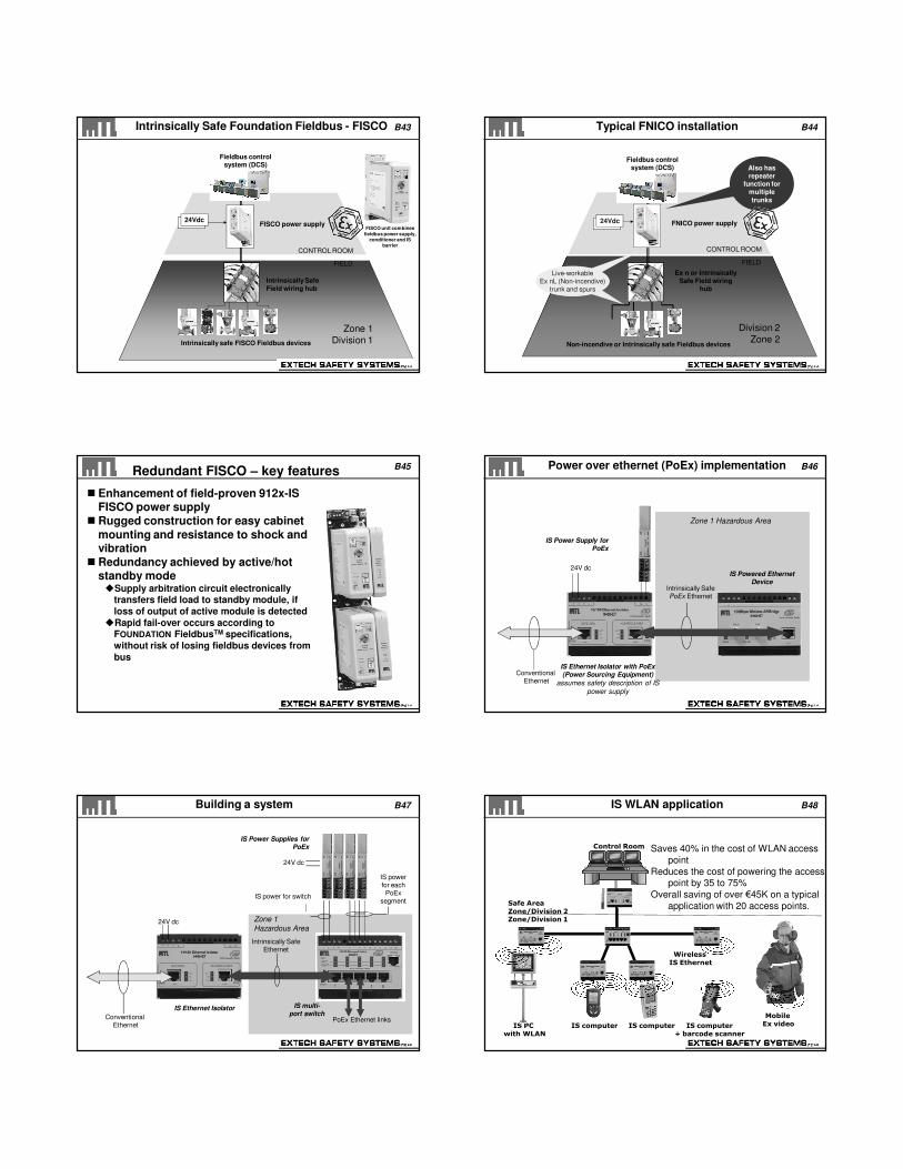
B43Intrinsically Safe Foundation Fieldbus - FISCO
FISCO power supply
FIELD
CONTROL ROOM
Intrinsically Safe Field wiring hub
Intrinsically safe FISCO Fieldbus devices
Zone 1
Division 1
24Vdc24Vdc
Fieldbus control system (DCS)
FISCO unit combines
fieldbus power supply, conditioner and IS
barrier
B44Typical FNICO installation
FNICO power supply
Ex n or Intrinsically Safe Field wiring
hub
Non-incendive or Intrinsically safe Fieldbus devices
Division 2
Zone 2
24Vdc24Vdc
FIELD
CONTROL ROOM
Live-workableNon-incendivetrunk and spurs
Live-workableEx nL (Non-incendive)
trunk and spurs
Fieldbus control system (DCS) Also has
repeater function for
multiple
trunks
B45Redundant FISCO – key features
Enhancement of field-proven 912x-IS FISCO power supply
Rugged construction for easy cabinet mounting and resistance to shock and vibration
Redundancy achieved by active/hot standby modeSupply arbitration circuit electronically
transfers field load to standby module, if loss of output of active module is detected
Rapid fail-over occurs according to FOUNDATION FieldbusTM specifications, without risk of losing fieldbus devices from bus
B46
Zone 1 Hazardous Area
Power over ethernet (PoEx) implementation
24V dc
Intrinsically Safe PoEx Ethernet
ConventionalEthernet
IS Powered Ethernet Device
IS Ethernet Isolator with PoEx(Power Sourcing Equipment)
assumes safety description of IS
power supply
IS Power Supply for PoEx
B47
Intrinsically Safe Ethernet
Zone 1
Hazardous Area
Building a system
24V dc
ConventionalEthernet
IS multi-port switch
IS Ethernet Isolator
IS Power Supplies for PoEx
PoEx Ethernet links
IS power for switch
IS powerfor each
PoExsegment
24V dc
B48IS WLAN application
Control Room
IS PCwith WLAN
Mobile Ex videoIS computer
+ barcode scannerIS computerIS computer
Safe AreaZone/Division 2Zone/Division 1
Saves 40% in the cost of WLAN access
point
Reduces the cost of powering the access point by 35 to 75%
Overall saving of over €45K on a typical
application with 20 access points.
Wireless IS Ethernet
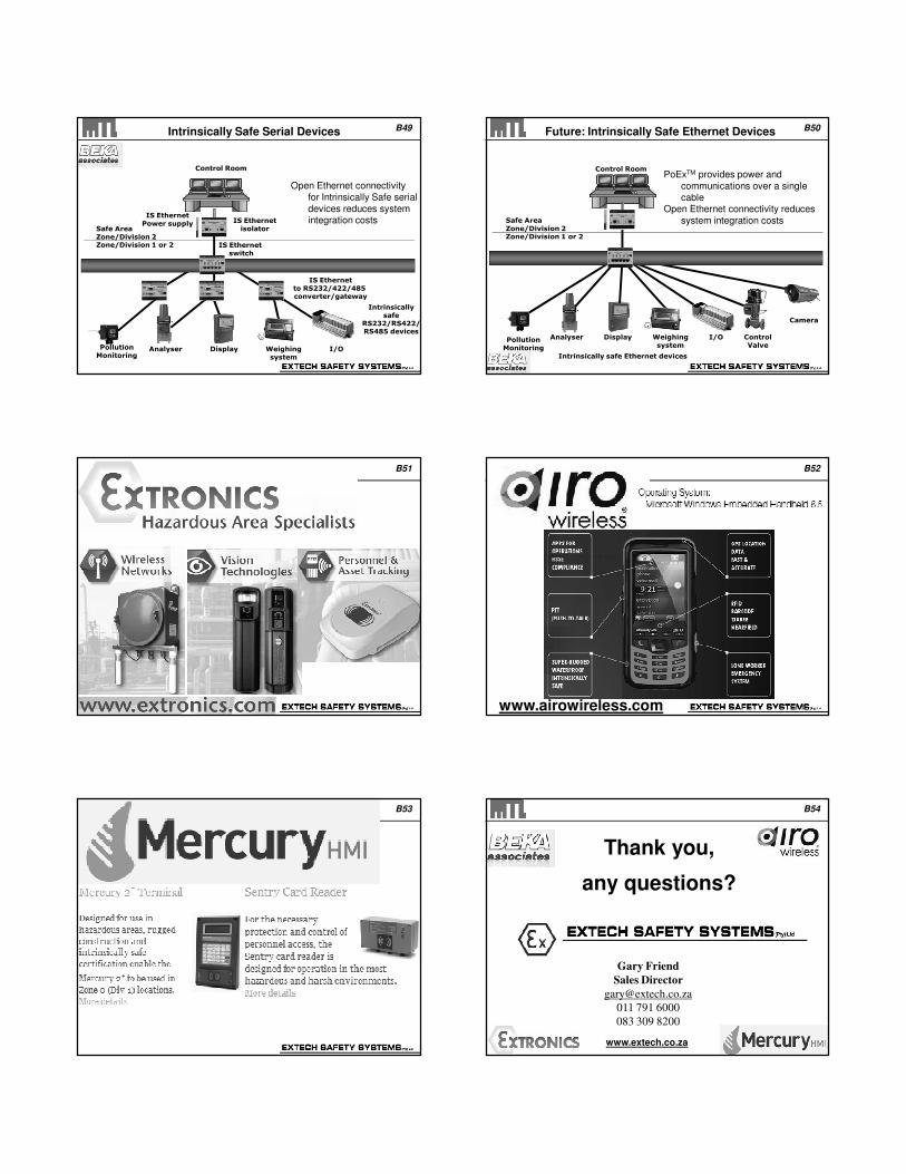
B49Intrinsically Safe Serial Devices
Control Room
Intrinsically safe
RS232/RS422/RS485 devices
IS Ethernetto RS232/422/485 converter/gateway
Weighingsystem
DisplayAnalyserPollutionMonitoring
I/O
Open Ethernet connectivity
for Intrinsically Safe serial
devices reduces system integration costs
Safe AreaZone/Division 2Zone/Division 1 or 2
IS Ethernetisolator
IS Ethernetswitch
IS EthernetPower supply
B50Future: Intrinsically Safe Ethernet Devices
Control Room
Intrinsically safe Ethernet devices
Weighingsystem
DisplayAnalyserPollutionMonitoring
ControlValve
I/O
PoExTM provides power and
communications over a single
cableOpen Ethernet connectivity reduces
system integration costs
Camera
Safe AreaZone/Division 2Zone/Division 1 or 2
B51Extronics B52
www.airowireless.com
B53 B54
Gary Friend
Sales Director
011 791 6000
083 309 8200
Thank you,
any questions?
www.extech.co.za