Embed Size (px)
Citation preview
Interrupts http://www.best-microcontroller-projects.com/hardware-interrupt.html Hardware interrupt Common terms
Terms you might hear associated with hardware interrupts are ISR, interrupt mask, non maskable interrupt, an asynchronous event, interrupt vector and context switching.
ISR Interrupt Service Routine.
Interrupt vector The address that holds the location of the ISR.
Interrupt mask Controls which interrupts are active.
NMI Non Maskable Interrupt - an interrupt that is always active.
Asynchronous event
An event that could happen at any time.
Context switching Saving/restoring data before & after the ISR.
ISR
An ISR is simply another program function. It is no different to any other function except that it does context switching (saving/restoring processor registers) and at the end of the function it re-enables interrupts.
After the ISR finishes program execution returns to the original program and it continues exactly from where it was interrupted. The orriginal program will have no idea that this has happened.
Hardware Interrupt vector
This is a fixed address that contains the location of your ISR – for a PIC micro it is usually address 4. In other micros there may be an interrupt vector for each vector – you have to make an interrupt routine for each one that you want to use. For PIC micros you have just one interrupt and you have to detect which interrupt triggered by examining the interrupt flag register(s).
You program the interrupt address with the address of your interrupt routine. Whenever the interrupt is triggered (and if the interrupt is
unmasked) program operation jumps to the location of your interrupt routine.
Note: high level language compilers take care of all of this for you - in 'C' you just declare the function using the keyword interrupt (as the type returned from the function). It then puts the address of this routine in the interrupt vector.
NMI
The NMI is exactly the same as a normal interrupt except that you can not control whether or not it is active - it's always active. It is more commonly found on larger (non-microcontroller) processors as a dedicated input pin. In this case it is more than likely fed with a brown-out (PSU voltage dip) detector circuit.
You don't need it in a microcontroller as you can achieve exactly the same functionality using a programmable interrupt and many microcontrollers have built in BODs.
Asynchronous event
This is simply an event that is not synchronised to the processor clock. It is an event that the processor can not predict e.g. A button press.
Context switching
This means that the register state is preserved at the start of an ISR and restored at the end of an ISR. It ensures that the function that was interrupted is not affected by the ISR.
A Basic Interrupt System.
This is a general description of an interrupt system (biased slightly to PIC micros) which is true for any interrupt module and it is useful for understanding how to control and use interrupts.
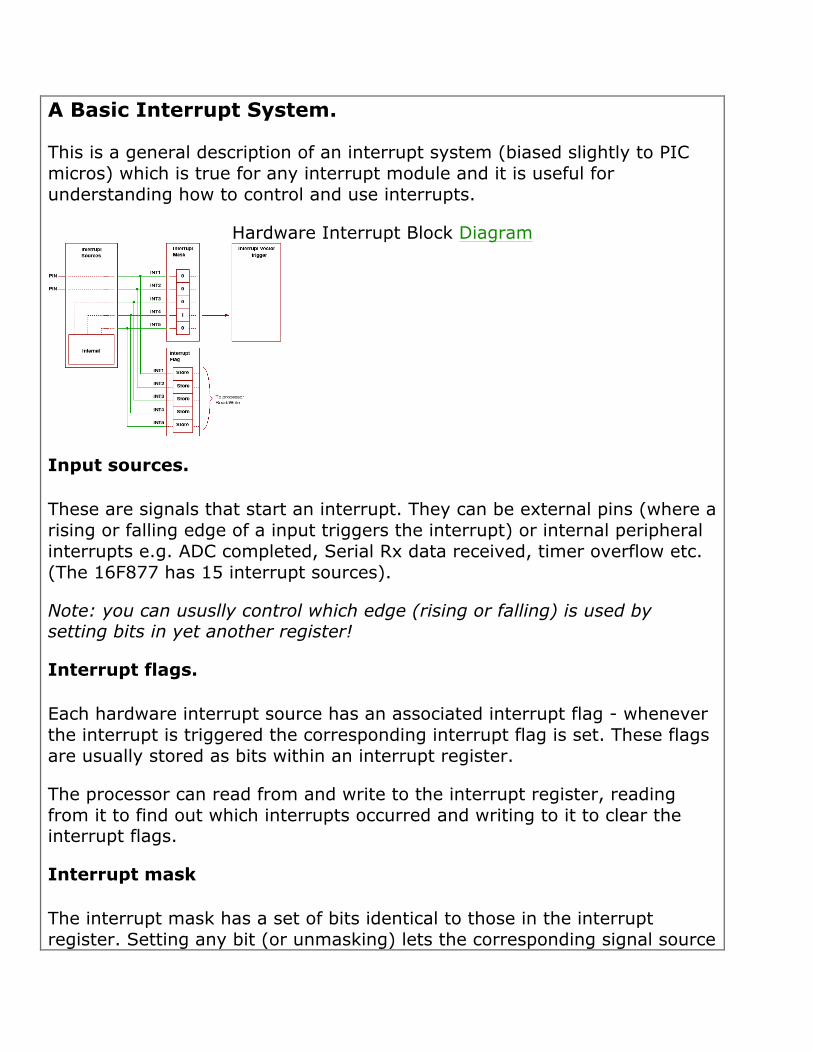
Hardware Interrupt Block Diagram
Input sources.
These are signals that start an interrupt. They can be external pins (where a rising or falling edge of a input triggers the interrupt) or internal peripheral interrupts e.g. ADC completed, Serial Rx data received, timer overflow etc. (The 16F877 has 15 interrupt sources).
Note: you can ususlly control which edge (rising or falling) is used by setting bits in yet another register!
Interrupt flags.
Each hardware interrupt source has an associated interrupt flag - whenever the interrupt is triggered the corresponding interrupt flag is set. These flags are usually stored as bits within an interrupt register.
The processor can read from and write to the interrupt register, reading from it to find out which interrupts occurred and writing to it to clear the interrupt flags.
Interrupt mask
The interrupt mask has a set of bits identical to those in the interrupt register. Setting any bit (or unmasking) lets the corresponding signal source
generate an interrupt - causing the processor to execute the ISR.
Note: When a bit in the mask is clear (masked) the ISR is not activated for that signal source but the interrupt register is still set by the signal source. So you can still detect what the hardware is doing by polling the interrupt register.
Hardware interrupt vector
The interrupt vector is a location in memory that you program with the address of your interrupt service routine (ISR). Whenever an unmasked interrupt occurs program execution starts from the address contained in the interrupt vector.
For PlC micros the hardware interrupt vector address is usually 0004.
BCF INTCON, GIE http://hobbyprojects.com/pic_tutorials/tutorial13.html http://hobbyprojects.com/pic_tutorials/tutorial11.html [at end of this] The masking of interrupts seems well illustrated in an example found in above |------ INTE ---- | Processor A --- GIE --- |------ RBIE ---- | |------ TOIE ---- “Current can travel from A to the processor only if GIE is "closed" and at least one of the mask bits is closed. Mask bits may be closed, but if GIE is open, no current flows. Along the same line, the processor can only b interrupted if one of the mask bits is set and the GIE bit is set. Thus, at some point in your routine, you are ready to accept interrupts. Set the appropriate mask bit (INTE, RBIE or TOIE) and set GIE. When no further interrupts are desired, either clear GIE or the mask bits or both.”
In addition to each mask that ids an interrupt as enabled, there is a flag bit that is set when that particular device/event interrupts. FLAG is an easy way to figure who set the interrupt and MUST be cleared before you finish the interrupt routine or the processor will fail to recognize that the interrupt request was serviced. Failure to clear the flag bit is interpreted by the processor as "a previous interrupt occurred, but the user has yet to service the interrupt". Thus, although an interrupt event may occur, GIE may be enabled and a mask bit may be set, the actual interrupt will not occur unless the corresponding flag bit is clear. “On interrupt, the processor clears the GIE bit thus inhibiting any further interrupts. The bit is again set on execution of the return from interrupts (RETFIE). Note that the programmer need not perform this book keeping.” So the PIC clears the general interrupt enable and therefore no more interrupts can occur. Note that if an intervening other device requests service it will not interrupt but the flag should be set. SO you need to check all flags FROM Pic website
INTERRUPT SYSTEM
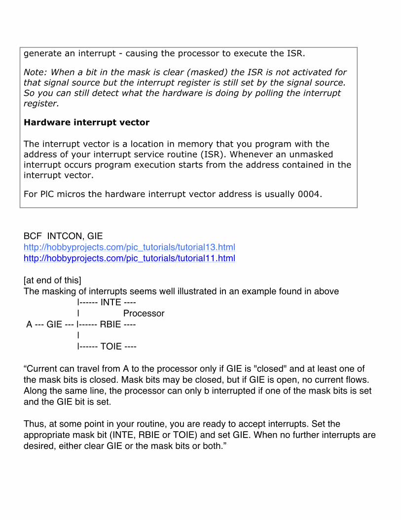
The first thing the microcontroller does when an interrupt request arrives is to execute the current instruction and then stops the regular program execution. As a result, the current program memory address is automatically pushed onto the stack and the default address (predefined by the manufacturer) is written to the program counter. The location from where the program proceeds with execution is called an interrupt vector. For the PIC16F887 microcontroller, this address is 0004h. As seen in figure below, the location containing the interrupt vector is passed over during regular program execution.
A part of the program to be executed when an interrupt request arrives is called an interrupt routine. Its first instruction is located at the interrupt vector. How long will it take to execute this subroutine and what it will be like depends on the skills of the programmer as well as on the interrupt source itself. Some of the microcontrollers have more interrupt vectors (every interrupt request has its vector), but in this case there is only one. Consequently, the first part of the interrupt routine consists in interrupt source detection.
Finally, when the interrupt source is recognized and the interrupt routine is executed, the microcontroller reaches the RETFIE instruction, pops the address from the stack and proceeds with program execution from where it left off.
mikroC recognizes an interrupt routine to be executed as the void interrupt() function. The body of that function, i.e. interrupt routine, should be written by the user.
INTERRUPT SYSTEM REGISTERS
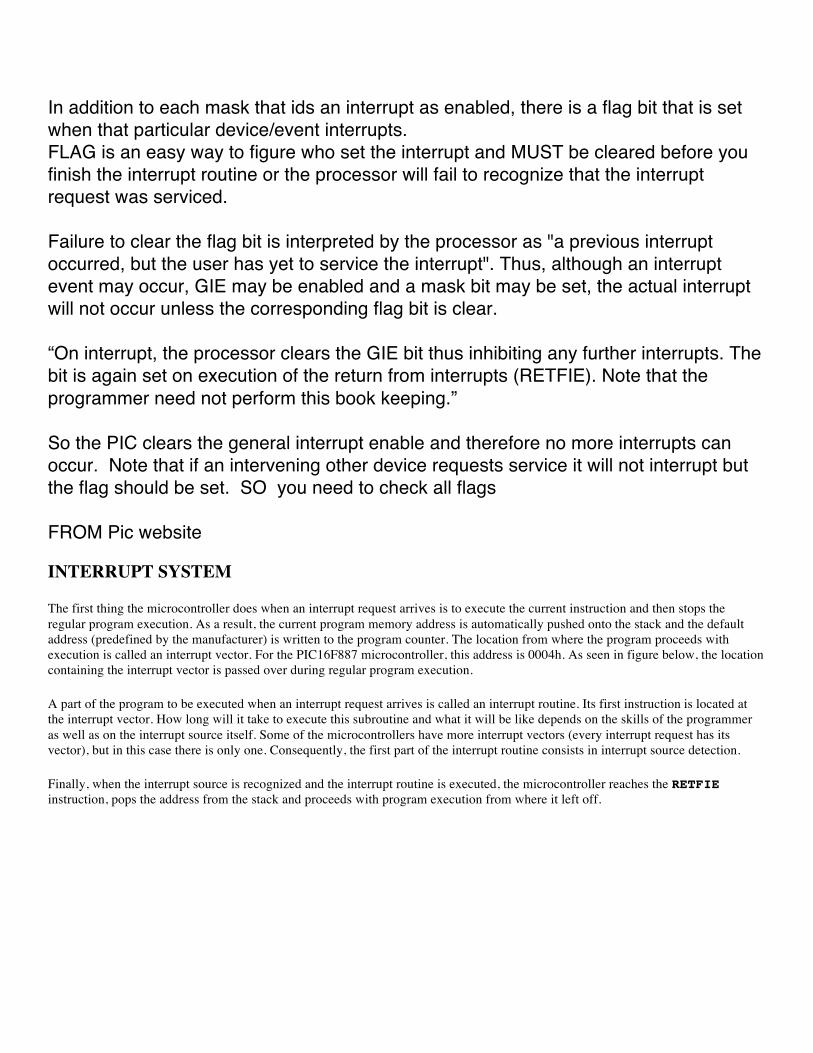
When an interrupt request arrives, it doesn’t mean that an interrupt will automatically occur, because it must also be enabled by the user (from within the program). Because of this, there are special bits used to enable or disable interrupts. It is easy to recognize them by the letters IE contained in their names (stands for Interrupt Enable). Besides, each interrupt is associated with another bit called the flag which indicates that an interrupt request has arrived regardless of whether it is enabled or not. They are also easily recognizable by the last two letters contained in their names- IF (Interrupt Flag).
As seen, everything is based on a simple and efficient idea. When an interrupt request arrives, the flag bit is set first.
If the appropriate IE bit is not set (0), this condition will be completely ignored. Otherwise, an interrupt occurs! If several interrupt sources are enabled, it is necessary to detect the active one before the interrupt routine starts execution. Source detection is performed by checking flag bits.
It is important to know that the flag bits are not automatically cleared, but by software while the interrupt routine execution is in progress. If we neglect this detail, another interrupt will occur immediately after returning to the main program, even though there are no more requests for its execution. Simply put, the flag, as well as the IE bit, remain set.
All interrupt sources typical of the PIC16F887 microcontroller are shown on the next page. Note several things:
The GIE bit enables all unmasked interrupts and disables all interrupts simultaneously.
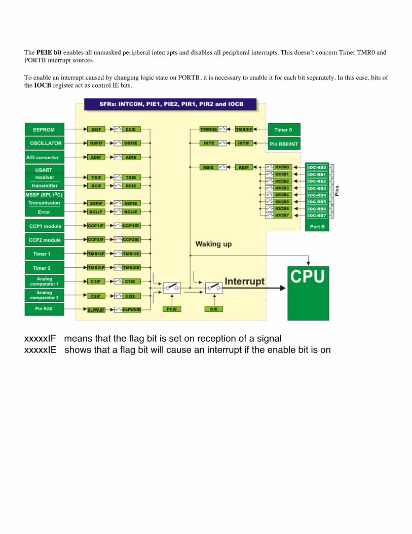
The PEIE bit enables all unmasked peripheral interrupts and disables all peripheral interrupts. This doesn’t concern Timer TMR0 and PORTB interrupt sources.
To enable an interrupt caused by changing logic state on PORTB, it is necessary to enable it for each bit separately. In this case, bits of the IOCB register act as control IE bits.
xxxxxIF means that the flag bit is set on reception of a signal xxxxxIE shows that a flag bit will cause an interrupt if the enable bit is on
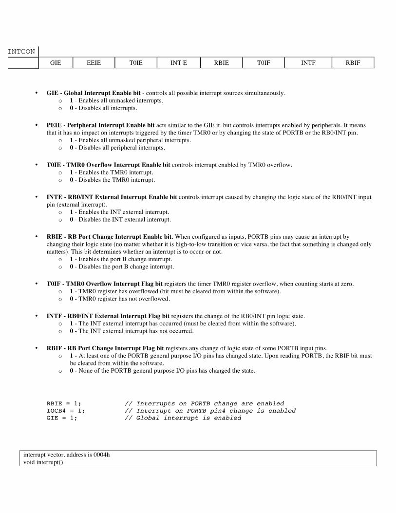
INTCON GIE EEIE T0IE INT E RBIE T0IF INTF RBIF
• GIE - Global Interrupt Enable bit - controls all possible interrupt sources simultaneously. o 1 - Enables all unmasked interrupts. o 0 - Disables all interrupts.
• PEIE - Peripheral Interrupt Enable bit acts similar to the GIE it, but controls interrupts enabled by peripherals. It means that it has no impact on interrupts triggered by the timer TMR0 or by changing the state of PORTB or the RB0/INT pin.
o 1 - Enables all unmasked peripheral interrupts. o 0 - Disables all peripheral interrupts.
• T0IE - TMR0 Overflow Interrupt Enable bit controls interrupt enabled by TMR0 overflow. o 1 - Enables the TMR0 interrupt. o 0 - Disables the TMR0 interrupt.
• INTE - RB0/INT External Interrupt Enable bit controls interrupt caused by changing the logic state of the RB0/INT input pin (external interrupt).
o 1 - Enables the INT external interrupt. o 0 - Disables the INT external interrupt.
• RBIE - RB Port Change Interrupt Enable bit. When configured as inputs, PORTB pins may cause an interrupt by changing their logic state (no matter whether it is high-to-low transition or vice versa, the fact that something is changed only matters). This bit determines whether an interrupt is to occur or not.
o 1 - Enables the port B change interrupt. o 0 - Disables the port B change interrupt.
• T0IF - TMR0 Overflow Interrupt Flag bit registers the timer TMR0 register overflow, when counting starts at zero. o 1 - TMR0 register has overflowed (bit must be cleared from within the software). o 0 - TMR0 register has not overflowed.
• INTF - RB0/INT External Interrupt Flag bit registers the change of the RB0/INT pin logic state. o 1 - The INT external interrupt has occurred (must be cleared from within the software). o 0 - The INT external interrupt has not occurred.
• RBIF - RB Port Change Interrupt Flag bit registers any change of logic state of some PORTB input pins. o 1 - At least one of the PORTB general purpose I/O pins has changed state. Upon reading PORTB, the RBIF bit must
be cleared from within the software. o 0 - None of the PORTB general purpose I/O pins has changed the state.
RBIE = 1; // Interrupts on PORTB change are enabled IOCB4 = 1; // Interrupt on PORTB pin4 change is enabled GIE = 1; // Global interrupt is enabled
interrupt vector. address is 0004h void interrupt()
RETFIE final instruction Accessing Individual Bits The mikroC PRO for PIC allows you to access individual bits of 8-bit variables. It also supports sbit and bit data types.
sbit type
The mikroC PRO for PIC compiler has sbit data type which provides access to registers, SFRs, variables, etc. You can declare a sbit variable in a unit in such way that it points to a specific bit in SFR register:
extern sfr sbit Abit; // Abit is precisely defined in some external file
Here is the way that the C-code is setup
const register unsigned short int GIE = 7; sbit GIE_bit at INTCON.B7; so GIE is set to the value 7 & GIE_BIT points at the INTCON register’s bit 7 The global variables defined allow us direct member selector (.) with a variable, followed by one of identifiers B0, B1, … , B7, or F0, F1, … F7, with F7 being the most significant bit INTCON.B0 = 0; // clear INTCON.F0 = 1; // set
assembler level instructions asm CLRWDT; // Assembly command to reset WDT interrupts etc from the hobby website ===== http://hobbyprojects.com/pic_tutorials/tutorial11.html
Interrupts - An Introduction The subject of interrupts is probably going to be the longest and most difficult to go through. There is no easy way of explaining interrupts, but hopefully by the end of this section you will be able to implement interrupts into your own programs. We have split the section into two parts. This is to help break the subject up, and to give you, the reader, a break.
So what is an interrupt? Well, as the name suggests, an interrupt is a process or a signal that stops a microprocessor/microcontroller from what it is doing so that something else can happen. Let me give you an every day example. Suppose you are sitting at home, chatting to someone. Suddenly the telephone rings. You stop chatting, and pick up the telephone to speak to the caller. When you have finished your telephone conversation, you go back to chatting to the person before the telephone rang. You can think of the main

routine as you chatting to someone, the telephone ringing causes you to interrupt your chatting, and the interrupt routine is the process of talking on the telephone. When the telephone conversation has ended, you then go back to your main routine of chatting. This example is exactly how an interrupt causes a processor to act. The main program is running, performing some function in a circuit, but when an interrupt occurs the main program halts while another routine is carried out. When this routine finishes, the processor goes back to the main routine again.
The PIC has 4 sources of interrupt. They can be split into two groups. Two are sources of interrupts that can be applied externally to the PIC, while the other two are internal processes. We are going to explain the two external ones here. The other two will be explained in other tutorials when we come to look at timers and storing data.
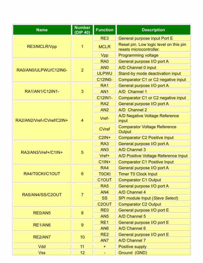
If you look at the pin-out of the PIC, you will see that pin 6 shows it is RB0/INT. Now, RB0 is obviously Port B bit 0. The INT symbolizes that it can also be configures as an external interrupt pin. Also, Port B bits 4 to 7 (pins 10 to 13) can also be used for interrupts. Before we can use the INT or other Port B pins, we need to do two things. First we need to tell the PIC that we are going to use interrupts. Secondly, we need to specify which port B pin we will be using as an interrupt and not as an I/O pin.
Inside the PIC there is a register called INTCON, and is at address 0Bh. Within this register there are 8 bits that can be enabled or disabled. Bit 7 of INTCON is called GIE. This is the Global Interrngupt Enable. Setting this to 1 tells the PIC that we are going to use an interrupt. Bit 4 of INTCON is called INTE, which means INTerrupt Enable. Setting this bit to 1 tells the PIC that RB0 will be an interrupt pin. Setting bit 3, called RBIE, tells the PIc that we will be using Port B bits 4 to 7. Now the PIC knows when this pin goes high or low, it will need to stop what it’s doing and get on with an interrupt routine. Now, we need to tell the PIC whether the interrupt is going to be on the rising edge (0V to +5V) or the falling edge (+5V to 0V) transition of the signal. In other words, do we want the PIC to interrupt when the signal goes from low to high, or from high to low. By default, this is set up to be on the rising edge. The edge ‘triggering’ is set up in another register called the OPTION register, at address 81h. The bit we are interested in is bit 6, which is called INTEDG. Setting this to 1 will cause the PIC to interrupt on the rising edge (default state) and setting it to 0 will cause the PIC to interrupt on the falling edge. If you want the PIC to trigger on the rising edge, then you don’t need to do anything to this bit. Now, unfortunately, the Option register is in Bank 1, which means that we have to change from bank 0 to bank 1, set the bit in the Option register, then come back to bank 0. The trick here is to do all of the Bank 1 registers in one hit, such as setting up the port pins, then coming back to Bank 0 when you are finished.
Ok, so now we have told the PIC which pin is going to be the interrupt, and on which edge to trigger, what happens in the program and the PIC when the interrupt occurs? Two things happen. First, a ‘flag’ is set. This tells the internal processor of the PIC that an interrupt has occurred. Secondly, the program counter (which we mentioned in the last tutorial) points to a particular address within the PIC. Let’s quickly look at each of these separately.
Interrupt Flag
In our INTCON register, bit 1 is the interrupt flag, called INTF. Now, when any interrupt occurs, this flag will be set to 1. While there isn’t an interrupt, the flag is set to 0. And that is all it does. Now you are probably thinking ‘what is the point?’ Well, while this flag is set to 1, the PIC cannot, and will not, respond to any other interrupt. So, let’s say that we cause an interrupt. The flag will be set to 1, and the PIC will go to our routine for processing the interrupt. If this flag wasn’t set to 1, and the PIC was allowed to keep responding to the interrupt, then continually pulsing the pin will keep the PIC going back to the start of our interrupt routine, and never finishing it. Going back to my example of the telephone, it’s like picking up the telephone, and just as soon as you start to speak it starts ringing again because someone else want to talk to you. It is far better to finish one conversation, then pick up the phone again to talk to the second person.
There is a slight drawback to this flag. Although the PIC automatically sets this flag to 1, it doesn’t set it back to 0! That task has to be done by the programmer – i.e. you. This is easily done, as We are sure you can guess, and has to be done after the PIC has executed the interrupt routine.
Memory Location
When you first power up the PIC, or if there is a reset, the Program Counter points to address 0000h, which is right at the start of the program memory. However, when there is an interrupt, the Program Counter will point to address 0004h. So, when we are writing our
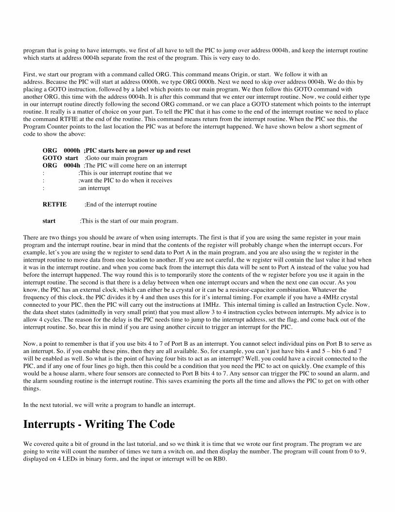
program that is going to have interrupts, we first of all have to tell the PIC to jump over address 0004h, and keep the interrupt routine which starts at address 0004h separate from the rest of the program. This is very easy to do.
First, we start our program with a command called ORG. This command means Origin, or start. We follow it with an address. Because the PIC will start at address 0000h, we type ORG 0000h. Next we need to skip over address 0004h. We do this by placing a GOTO instruction, followed by a label which points to our main program. We then follow this GOTO command with another ORG, this time with the address 0004h. It is after this command that we enter our interrupt routine. Now, we could either type in our interrupt routine directly following the second ORG command, or we can place a GOTO statement which points to the interrupt routine. It really is a matter of choice on your part. To tell the PIC that it has come to the end of the interrupt routine we need to place the command RTFIE at the end of the routine. This command means return from the interrupt routine. When the PIC see this, the Program Counter points to the last location the PIC was at before the interrupt happened. We have shown below a short segment of code to show the above:
ORG 0000h ;PIC starts here on power up and reset GOTO start ;Goto our main program ORG 0004h ;The PIC will come here on an interrupt : ;This is our interrupt routine that we : ;want the PIC to do when it receives : ;an interrupt
RETFIE ;End of the interrupt routine
start ;This is the start of our main program.
There are two things you should be aware of when using interrupts. The first is that if you are using the same register in your main program and the interrupt routine, bear in mind that the contents of the register will probably change when the interrupt occurs. For example, let’s you are using the w register to send data to Port A in the main program, and you are also using the w register in the interrupt routine to move data from one location to another. If you are not careful, the w register will contain the last value it had when it was in the interrupt routine, and when you come back from the interrupt this data will be sent to Port A instead of the value you had before the interrupt happened. The way round this is to temporarily store the contents of the w register before you use it again in the interrupt routine. The second is that there is a delay between when one interrupt occurs and when the next one can occur. As you know, the PIC has an external clock, which can either be a crystal or it can be a resistor-capacitor combination. Whatever the frequency of this clock, the PIC divides it by 4 and then uses this for it’s internal timing. For example if you have a 4MHz crystal connected to your PIC, then the PIC will carry out the instructions at 1MHz. This internal timing is called an Instruction Cycle. Now, the data sheet states (admittedly in very small print) that you must allow 3 to 4 instruction cycles between interrupts. My advice is to allow 4 cycles. The reason for the delay is the PIC needs time to jump to the interrupt address, set the flag, and come back out of the interrupt routine. So, bear this in mind if you are using another circuit to trigger an interrupt for the PIC.
Now, a point to remember is that if you use bits 4 to 7 of Port B as an interrupt. You cannot select individual pins on Port B to serve as an interrupt. So, if you enable these pins, then they are all available. So, for example, you can’t just have bits 4 and 5 – bits 6 and 7 will be enabled as well. So what is the point of having four bits to act as an interrupt? Well, you could have a circuit connected to the PIC, and if any one of four lines go high, then this could be a condition that you need the PIC to act on quickly. One example of this would be a house alarm, where four sensors are connected to Port B bits 4 to 7. Any sensor can trigger the PIC to sound an alarm, and the alarm sounding routine is the interrupt routine. This saves examining the ports all the time and allows the PIC to get on with other things.
In the next tutorial, we will write a program to handle an interrupt.
Interrupts - Writing The Code We covered quite a bit of ground in the last tutorial, and so we think it is time that we wrote our first program. The program we are going to write will count the number of times we turn a switch on, and then display the number. The program will count from 0 to 9, displayed on 4 LEDs in binary form, and the input or interrupt will be on RB0.
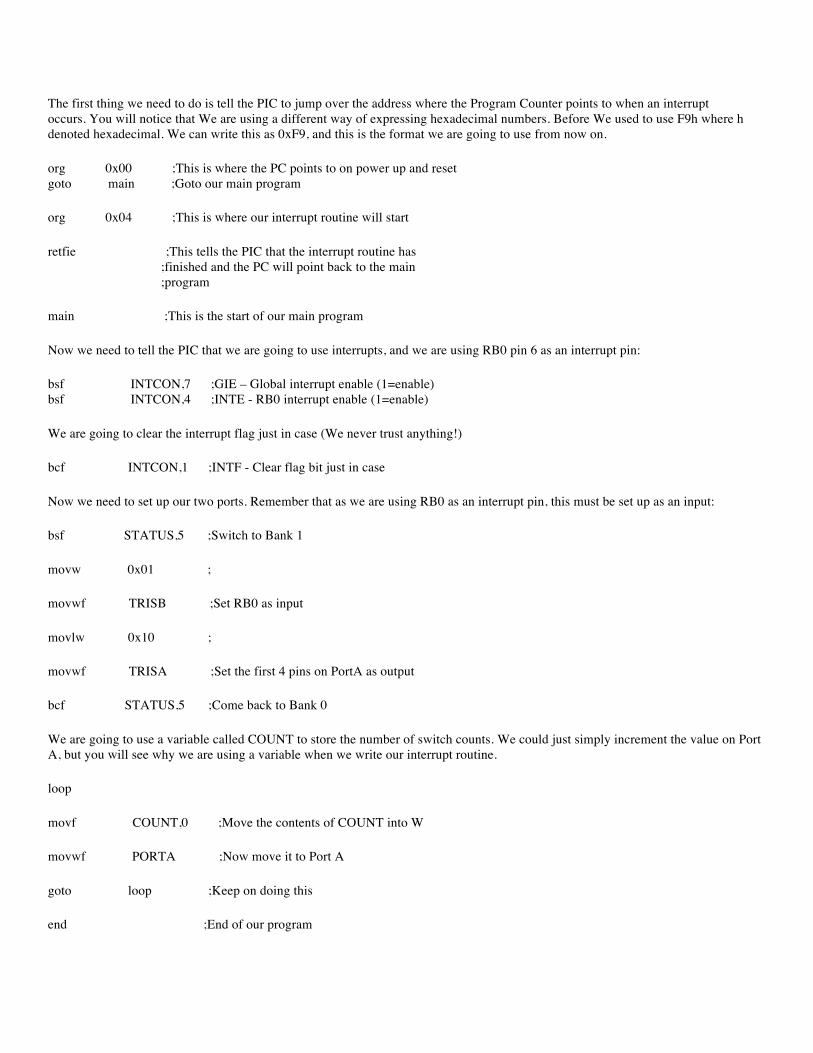
The first thing we need to do is tell the PIC to jump over the address where the Program Counter points to when an interrupt occurs. You will notice that We are using a different way of expressing hexadecimal numbers. Before We used to use F9h where h denoted hexadecimal. We can write this as 0xF9, and this is the format we are going to use from now on.
org 0x00 ;This is where the PC points to on power up and reset goto main ;Goto our main program
org 0x04 ;This is where our interrupt routine will start
retfie ;This tells the PIC that the interrupt routine has ;finished and the PC will point back to the main ;program
main ;This is the start of our main program
Now we need to tell the PIC that we are going to use interrupts, and we are using RB0 pin 6 as an interrupt pin:
bsf INTCON,7 ;GIE – Global interrupt enable (1=enable) bsf INTCON,4 ;INTE - RB0 interrupt enable (1=enable)
We are going to clear the interrupt flag just in case (We never trust anything!)
bcf INTCON,1 ;INTF - Clear flag bit just in case
Now we need to set up our two ports. Remember that as we are using RB0 as an interrupt pin, this must be set up as an input:
bsf STATUS,5 ;Switch to Bank 1
movw 0x01 ;
movwf TRISB ;Set RB0 as input
movlw 0x10 ;
movwf TRISA ;Set the first 4 pins on PortA as output
bcf STATUS,5 ;Come back to Bank 0
We are going to use a variable called COUNT to store the number of switch counts. We could just simply increment the value on Port A, but you will see why we are using a variable when we write our interrupt routine.
loop
movf COUNT,0 ;Move the contents of COUNT into W
movwf PORTA ;Now move it to Port A
goto loop ;Keep on doing this
end ;End of our program
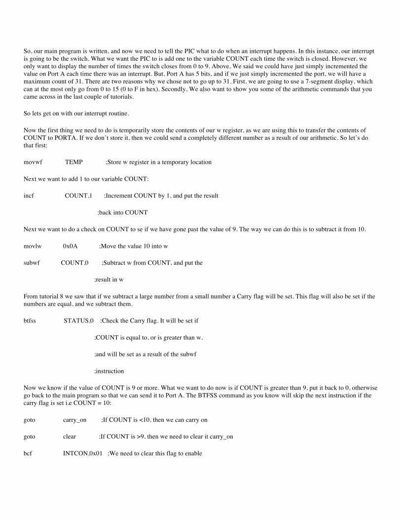
So, our main program is written, and now we need to tell the PIC what to do when an interrupt happens. In this instance, our interrupt is going to be the switch. What we want the PIC to is add one to the variable COUNT each time the switch is closed. However, we only want to display the number of times the switch closes from 0 to 9. Above, We said we could have just simply incremented the value on Port A each time there was an interrupt. But, Port A has 5 bits, and if we just simply incremented the port, we will have a maximum count of 31. There are two reasons why we chose not to go up to 31. First, we are going to use a 7-segment display, which can at the most only go from 0 to 15 (0 to F in hex). Secondly, We also want to show you some of the arithmetic commands that you came across in the last couple of tutorials.
So lets get on with our interrupt routine.
Now the first thing we need to do is temporarily store the contents of our w register, as we are using this to transfer the contents of COUNT to PORTA. If we don’t store it, then we could send a completely different number as a result of our arithmetic. So let’s do that first:
movwf TEMP ;Store w register in a temporary location
Next we want to add 1 to our variable COUNT:
incf COUNT,1 ;Increment COUNT by 1, and put the result
;back into COUNT
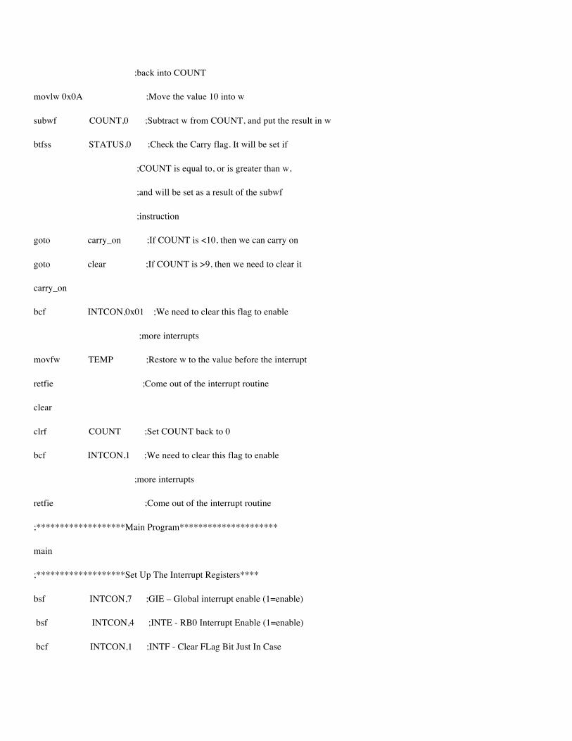
Next we want to do a check on COUNT to se if we have gone past the value of 9. The way we can do this is to subtract it from 10.
movlw 0x0A ;Move the value 10 into w
subwf COUNT,0 ;Subtract w from COUNT, and put the
;result in w
From tutorial 8 we saw that if we subtract a large number from a small number a Carry flag will be set. This flag will also be set if the numbers are equal, and we subtract them.
btfss STATUS,0 ;Check the Carry flag. It will be set if
;COUNT is equal to, or is greater than w,
;and will be set as a result of the subwf
;instruction
Now we know if the value of COUNT is 9 or more. What we want to do now is if COUNT is greater than 9, put it back to 0, otherwise go back to the main program so that we can send it to Port A. The BTFSS command as you know will skip the next instruction if the carry flag is set i.e COUNT = 10:
goto carry_on ;If COUNT is <10, then we can carry on
goto clear ;If COUNT is >9, then we need to clear it carry_on
bcf INTCON,0x01 ;We need to clear this flag to enable
;more interrupts
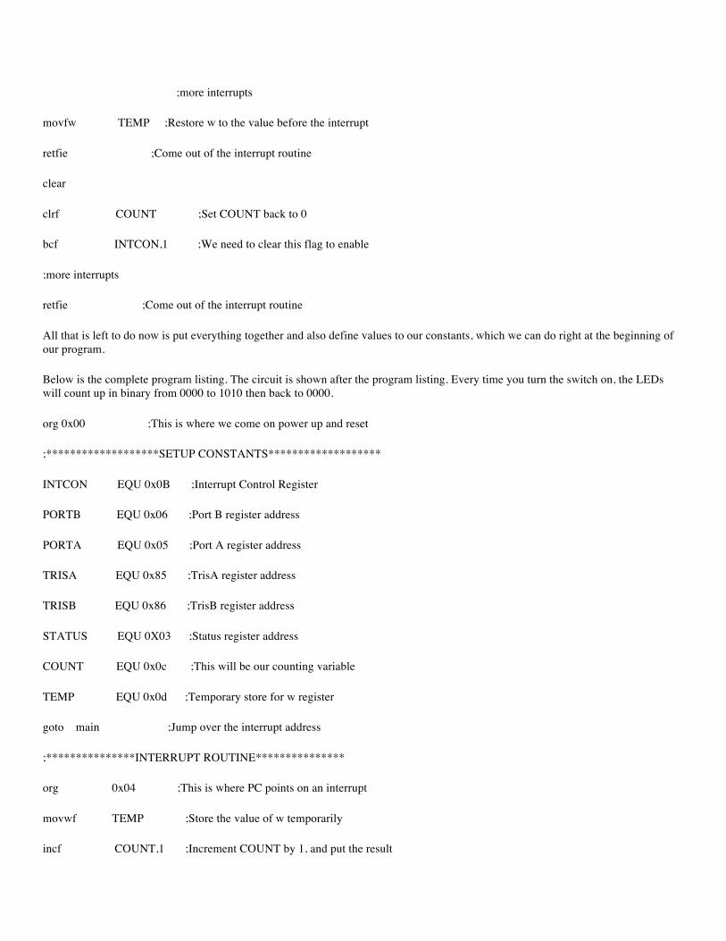
movfw TEMP ;Restore w to the value before the interrupt
retfie ;Come out of the interrupt routine
clear
clrf COUNT ;Set COUNT back to 0
bcf INTCON,1 ;We need to clear this flag to enable
;more interrupts
retfie ;Come out of the interrupt routine
All that is left to do now is put everything together and also define values to our constants, which we can do right at the beginning of our program.
Below is the complete program listing. The circuit is shown after the program listing. Every time you turn the switch on, the LEDs will count up in binary from 0000 to 1010 then back to 0000.
org 0x00 ;This is where we come on power up and reset
;*******************SETUP CONSTANTS*******************
INTCON EQU 0x0B ;Interrupt Control Register
PORTB EQU 0x06 ;Port B register address
PORTA EQU 0x05 ;Port A register address
TRISA EQU 0x85 ;TrisA register address
TRISB EQU 0x86 ;TrisB register address
STATUS EQU 0X03 ;Status register address
COUNT EQU 0x0c ;This will be our counting variable
TEMP EQU 0x0d ;Temporary store for w register
goto main ;Jump over the interrupt address
;***************INTERRUPT ROUTINE***************
org 0x04 ;This is where PC points on an interrupt
movwf TEMP ;Store the value of w temporarily
incf COUNT,1 ;Increment COUNT by 1, and put the result
;back into COUNT
movlw 0x0A ;Move the value 10 into w
subwf COUNT,0 ;Subtract w from COUNT, and put the result in w
btfss STATUS,0 ;Check the Carry flag. It will be set if
;COUNT is equal to, or is greater than w,
;and will be set as a result of the subwf
;instruction
goto carry_on ;If COUNT is <10, then we can carry on
goto clear ;If COUNT is >9, then we need to clear it
carry_on
bcf INTCON,0x01 ;We need to clear this flag to enable
;more interrupts
movfw TEMP ;Restore w to the value before the interrupt
retfie ;Come out of the interrupt routine
clear
clrf COUNT ;Set COUNT back to 0
bcf INTCON,1 ;We need to clear this flag to enable
;more interrupts
retfie ;Come out of the interrupt routine
;*******************Main Program*********************
main
;*******************Set Up The Interrupt Registers****
bsf INTCON,7 ;GIE – Global interrupt enable (1=enable)
bsf INTCON,4 ;INTE - RB0 Interrupt Enable (1=enable)
bcf INTCON,1 ;INTF - Clear FLag Bit Just In Case
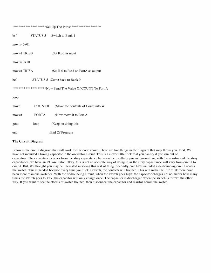
;*******************Set Up The Ports******************
bsf STATUS,5 ;Switch to Bank 1
movlw 0x01
movwf TRISB ;Set RB0 as input
movlw 0x10
movwf TRISA ;Set R 0 to RA3 on PortA as output
bcf STATUS,5 ;Come back to Bank 0
;*******************Now Send The Value Of COUNT To Port A
loop
movf COUNT,0 ;Move the contents of Count into W
movwf PORTA ;Now move it to Port A
goto loop ;Keep on doing this
end ;End Of Program
The Circuit Diagram
Below is the circuit diagram that will work for the code above. There are two things in the diagram that may throw you. First, We have not included a timing capacitor in the oscillator circuit. This is a clever little trick that you can try if you run out of capacitors. The capacitance comes from the stray capacitance between the oscillator pin and ground. so, with the resistor and the stray capacitance, we have an RC oscillator. Okay, this is not an accurate way of doing it, as the stray capacitance will vary from circuit to circuit. But, We thought you may be interested in seeing this sort of thing. Secondly, We have included a de-bouncing circuit across the switch. This is needed because every time you flick a switch, the contacts will bounce. This will make the PIC think there have been more than one switches. With the de-bouncing circuit, when the switch goes high, the capacitor charges up. no matter how many times the switch goes to +5V, the capacitor will only charge once. The capacitor is discharged when the switch is thrown the other way. If you want to see the effects of switch bounce, then disconnect the capacitor and resistor across the switch.
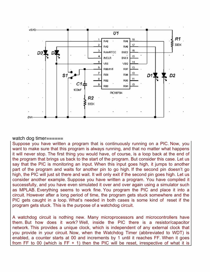
watch dog timer====== Suppose you have written a program that is continuously running on a PIC. Now, you want to make sure that this program is always running, and that no matter what happens it will never stop. The first thing you would have, of course, is a loop back at the end of the program that brings us back to the start of the program. But consider this case. Let us say that the PIC is monitoring an input. When this input goes high, it jumps to another part of the program and waits for another pin to go high. If the second pin doesn’t go high, the PIC will just sit there and wait. It will only exit if the second pin goes high. Let us consider another example. Suppose you have written a program. You have compiled it successfully, and you have even simulated it over and over again using a simulator such as MPLAB. Everything seems to work fine. You program the PIC and place it into a circuit. However after a long period of time, the program gets stuck somewhere and the PIC gets caught in a loop. What’s needed in both cases is some kind of reset if the program gets stuck. This is the purpose of a watchdog circuit.
A watchdog circuit is nothing new. Many microprocessors and microcontrollers have them. But how does it work? Well, inside the PIC there is a resistor/capacitor network. This provides a unique clock, which is independent of any external clock that you provide in your circuit. Now, when the Watchdog Timer (abbreviated to WDT) is enabled, a counter starts at 00 and increments by 1 until it reaches FF. When it goes from FF to 00 (which is FF + 1) then the PIC will be reset, irrespective of what it is
doing. The only way we can stop the WDT from resetting the PIC is to periodically reset the WDT back to 00 throughout our program. Now you can see that if our program does get stuck for some reason, then the WDT will not be set. The WDT will then reset the PIC, causing our program to restart from the beginning.
In order to use the WDT, we need to know three things. First, how long have we got before we need to reset the WDT, secondly how do we clear it. Finally, we have to tell the PIC programming software to enable the WDT inside the PIC. Let’s look at these separately.
WDT Times The PIC data sheet specifies that the WDT has a period from start to finish of 18mS. This is dependant several factors, such as the supply voltage, temperature of the PIC etc. The reason for the approximation is because the WDT clock is supplied by an internal RC network. The time for an RC network to charge depends on the supply voltage. It also depends on the component values, which will change slightly depending on their temperature. So, for the sake of simplicity, just take it that the WDT will reset every 18mS. We can, however, make this longer. Inside the PIC is a thing called a Prescaler. We can program this prescaler to divide the RC clock. The more we divide the RC clock by, the longer it takes for the WDT to reset.
The prescaler is located in the OPTION register at address 81h, bits 0 to 2 inclusive. Below is a table showing the bit assignments with the division rates and the time for the WDT to time out:
Bit 2,1,0
Rate WDT Time
0,0,0 1:1 18mS 0,0,1 1:2 36mS 0,1,0 1:4 72mS 0,1,1 1:8 144mS 1,0,0 1:16 288mS 1,0,1 1:32 576mS 1,1,0 1:64 1.1Seconds 1,1,1 1:128 2.3Seconds
Remember these times are irrespective of your external clock frequency. Think of these times as real time, rather than clock times. To help make this clear, let us suppose we want the WDT to reset our PIC after about half a second as a failsafe. The nearest we have is 576mS, or 0.576 seconds. All we do is send b’101’ to our OPTION register, as

follows:
movlw b’101’ ;This is 0x05 in Hex movwf 81h ;This is the Option Register
Simple, really. Now, there is a catch. By default the prescaler is assigned to the other internal timer. This means that we have to change the prescaler over to the WDT. First, we have to reset the other counter to 0 first. We then have to change to Bank 1 to assign the prescaler to the WDT and to set up the time, and then come back to Bank 0. The code is below, where xx is the prescaler time:
bcf STATUS,0 ;make sure we are in bank 0 clrf 01h ;address of the other timer – TMR0 bsf STATUS,0 ;switch to bank 1 clrwdt ;reset the WDT and prescaler movlw b’1xxx’ ;Select the new prescaler value and assign movwf OPTION ;it to WDT bcf STATUS,0 ;come back to bank 0
The CLRWDT command above is how we clear the WDT before it resets the PIC. So, all we need to do is calculate where in our program the WDT will time out, and then enter the CLRWDT command just before this point to ensure the PIC doesn’t reset. If your program is long, bear in mind that you may need more than one CLRWDT. For example, if we use the default time of 18mS, then we need to make sure that the program will see CLRWDT every 18mS.
So now we come to the point where we need to work out how long our code takes in real time. The principle is very simple, but could cause you to pull your hair out!
Instruction Timing As you are probably already aware, the PIC takes the external clock timing and divides it by 4. This internal time is called an instruction cycle. Now if we have, say, a 4MHz xtal connected to the PIC, internally the PIC will run at 1MHz. In timing terms, this is 1/(4MHz/4) = 1uS. Now, some instructions take just one instruction cycle to complete, i.e. 1uS using a 4MHz crystal, while others take two cycles – 2uS – to complete. The data sheet tells us how many cycles each instruction takes. The easiest way to remember this is quite simple. Assume ALL instructions take 1 cycle. But, if an instruction causes the program to go somewhere else, then it will take 2 cycles. Let me give you a couple of examples. The movwf command takes only one cycle, because it is only moving data from one place to another. The goto command takes 2 cycles, because it is causing the Program Counter (PC) to go elsewhere in the program. The RETURN command takes 2
cycles, because it is causing the PC to go back in the program. We think you can see the pattern here. However, there are four commands which can take 1 or 2 cycles. These are DECFSZ, INCFSZ, BTFSC and BTFSS. These commands have one thing in common. They will skip the next instruction is a certain condition is met. If that condition is not met, then the next instruction will be carried out. For example, the DECFSZ command will decrement the value stored in the F register by 1. If the result is not 0, then the next instruction will be executed. This instruction therefore takes 1 cycle. If the result is 0, then the next instruction will be skipped, and the one following that will be executed. In this instance the instruction takes 2 cycles. The reason is that the instruction alters the value of the PC. It needs one cycle to carry out the function, and it will need another to alter the PC by an extra one.
To clarify this, let us look at a sample code, and work out how many instruction cycles it takes.
movlw 02 movwf COUNT loop decfsz COUNT goto loop end
Our first instruction simply moves the value 02 into w. This does not cause the program to off course, therefore it is only 1 cycle. The next instruction is similar, in as much that it moves the contents of the w register into COUNT. Again, this will be 1 cycle. Now, the next instruction will first decrement COUNT by 1. This is 1 cycle. It will then do a test to see if COUNT is equal to 0. At this stage it doesn’t, and so we move onto the next instruction. The next instruction is a goto statement, and so is 2 cycles long. We come back to our decfsz instruction, which decrements COUNT by 1 again. This is another instruction cycle. It does a test to see if COUNT is equal to 0. This time it does, and so the next instruction is skipped. To skip the next instruction requires another cycle. We reach the end of the program. So in total, with the value 02 placed into COUNT, this program will take a total of 7 cycles. If we were using a 4MHz crystal for our clock, then the program will take:
1/(4MHz/4) = 1uS per cycle, therefore 7 cycles takes 7 x 1uS = 7uS.
So you can see that it can get a little confusing when you have instructions like DECFSZ.
Programmer Software Inside the PIC there are things called ‘Fuses’. These are not the same as the fuses you would find in a mains plug, but electronic switches which are ‘blown’ by the programmer. Now, one of these fuses has to be ‘blown’ in order for the WDT to operate. There are two ways of doing this. One way is to write a couple of lines at the
beginning of your program to tell the PIC programming software to enable or disable certain fuses. The other way is to tell the PIC programming software manually which fuses to enable. We will look at getting your program to instruct the programming software in a later tutorial, when we look at including other files and macros. To tell the programming software manually, varies from program to program. The documentation that came with the programmer should tell you how to do this. As We are using the PICALLW software, which is linked on my main page, We will explain how to do change fuses within this program. The fuses are configured by pressing the F3 key, or clicking on the ‘Config’ button. Then you can select the fuse you want enabled, in this case the WDT, by clicking on the box next to it.
Sample Program Let us write a program, where we will turn on the WDT, and let the PIC perform a function. We will first of all periodically clear the WDT, to show that the program works, and then remove the CLRWDT command to show that the PIC will indeed reset.
The program We have chosen is the one used in tutorial 9 where we cause a row of LEDs to light up one at a time from left to right, then right to left. The circuit is shown below, and with the RC values shown will give us a clock frequency of 8KHz. This clock speed will allow us to actually see the LEDs moving one by one. We chose this program because it is slow enough for us to play with the WDT, and you can easily see when the PIC is reset. We have removed the original comments, and We have replaced them with a description of the WDT lines, a running total of the time from the start (assuming a 8KHz clock), and the number of clock cycles at each line.
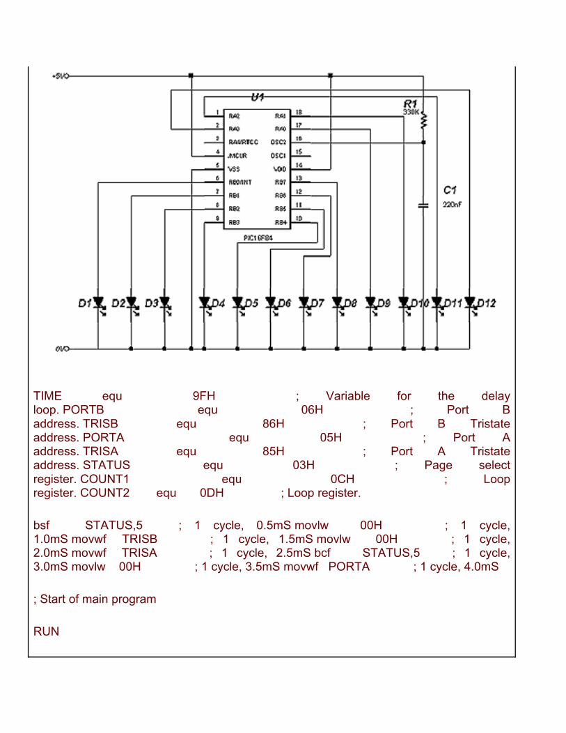
TIME equ 9FH ; Variable for the delay loop. PORTB equ 06H ; Port B address. TRISB equ 86H ; Port B Tristate address. PORTA equ 05H ; Port A address. TRISA equ 85H ; Port A Tristate address. STATUS equ 03H ; Page select register. COUNT1 equ 0CH ; Loop register. COUNT2 equ 0DH ; Loop register.
bsf STATUS,5 ; 1 cycle, 0.5mS movlw 00H ; 1 cycle, 1.0mS movwf TRISB ; 1 cycle, 1.5mS movlw 00H ; 1 cycle, 2.0mS movwf TRISA ; 1 cycle, 2.5mS bcf STATUS,5 ; 1 cycle, 3.0mS movlw 00H ; 1 cycle, 3.5mS movwf PORTA ; 1 cycle, 4.0mS
; Start of main program
RUN
movlw 01H ; 1 cycle, 4.5mS movwf PORTB ; 1 cycle, 5.0mS call DELAY ; 2 cycles, 486mS call DELAY ; 2 cycles, 967mS
; Move the bit on Port B left, then pause.
rlf PORTB,1 ; 1 cycle, 967.5mS call DELAY ; 2 cycles, 1.45S call DELAY ; 2 cycles, 1.93S rlf PORTB,1 ; 1 cycle, 1.93S call DELAY ; 2 cycles, 2.41S call DELAY ; 2 cycles, 2.89S rlf PORTB,1 ; 1 cycle, 2.89S call DELAY ; 2 cycles, 3.37S call DELAY ; 2 cycles, 3.85S rlf PORTB,1 ; 1 cycle, 3.85S call DELAY ; 2 cycles, 4.34S call DELAY ; 2 cycles, 4.82S rlf PORTB,1 ; 1 cycle, 4.82S call DELAY ; 2 cycles, 5.30S call DELAY ; 2 cycles, 5.78S rlf PORTB,1 ; 1 cycle, 5.78S call DELAY ; 2 cycles, 6.26S call DELAY ; 2 cycles, 6.74S rlf PORTB,1 ; 1 cycle, 6.74S call DELAY ; 2 cycles, 7.22S call DELAY ; 2 cycles, 7.70S rlf PORTB,1 ; 1 cycle, 7.70S
; Now move onto Port A, and move the bit left.
rlf PORTA,1 ; 1 cycle, 7.70S call DELAY ; 2 cycles, 8.19S call DELAY ; 2 cycles, 8.67S rlf PORTA,1 ; 1 cycle, 8.67S call DELAY ; 2 cycles, 9.15S call DELAY ; 2 cycles, 9.63S rlf PORTA,1 ; 1 cycle, 9.63S call DELAY ; 2 cycles, 10.11S call DELAY ; 2 cycles, 10.59S rlf PORTA,1 ; 1 cycle, 10.59S call DELAY ; 2 cycles, 11.07S call DELAY ; 2 cycles, 11.55S
; Move the bit back on Port A
rrf PORTA,1 ; 1 cycle, 11.55S call DELAY ; 2 cycles, 12.04S call DELAY ; 2 cycles, 12.52S rrf PORTA,1 ; 1 cycle, 12.52S call DELAY ; 2 cycles, 12.99S call DELAY ; 2 cycles, 13.48S rrf PORTA,1 ; 1 cycle, 13.48S call DELAY ; 2 cycles, 13.96S call DELAY ; 2 cycles, 14.44S rrf PORTA,1 ; 1
cycle, 14.44S
; Now move the bit back on Port B
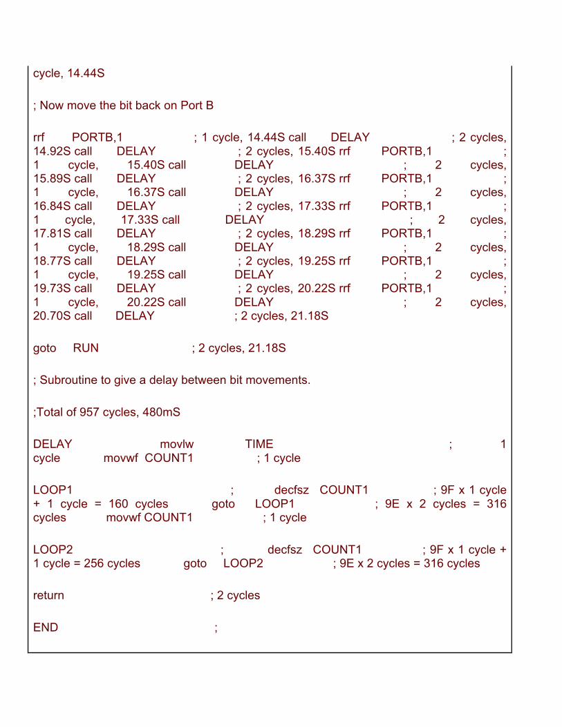
rrf PORTB,1 ; 1 cycle, 14.44S call DELAY ; 2 cycles, 14.92S call DELAY ; 2 cycles, 15.40S rrf PORTB,1 ; 1 cycle, 15.40S call DELAY ; 2 cycles, 15.89S call DELAY ; 2 cycles, 16.37S rrf PORTB,1 ; 1 cycle, 16.37S call DELAY ; 2 cycles, 16.84S call DELAY ; 2 cycles, 17.33S rrf PORTB,1 ; 1 cycle, 17.33S call DELAY ; 2 cycles, 17.81S call DELAY ; 2 cycles, 18.29S rrf PORTB,1 ; 1 cycle, 18.29S call DELAY ; 2 cycles, 18.77S call DELAY ; 2 cycles, 19.25S rrf PORTB,1 ; 1 cycle, 19.25S call DELAY ; 2 cycles, 19.73S call DELAY ; 2 cycles, 20.22S rrf PORTB,1 ; 1 cycle, 20.22S call DELAY ; 2 cycles, 20.70S call DELAY ; 2 cycles, 21.18S
goto RUN ; 2 cycles, 21.18S
; Subroutine to give a delay between bit movements.
;Total of 957 cycles, 480mS
DELAY movlw TIME ; 1 cycle movwf COUNT1 ; 1 cycle
LOOP1 ; decfsz COUNT1 ; 9F x 1 cycle + 1 cycle = 160 cycles goto LOOP1 ; 9E x 2 cycles = 316 cycles movwf COUNT1 ; 1 cycle
LOOP2 ; decfsz COUNT1 ; 9F x 1 cycle + 1 cycle = 256 cycles goto LOOP2 ; 9E x 2 cycles = 316 cycles
return ; 2 cycles
END ;
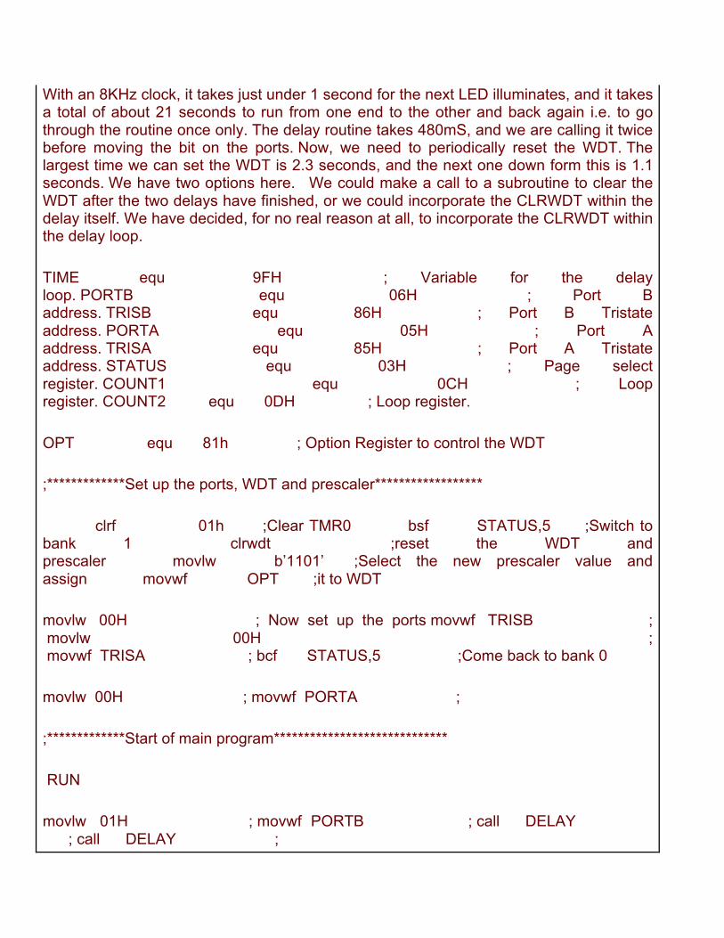
With an 8KHz clock, it takes just under 1 second for the next LED illuminates, and it takes a total of about 21 seconds to run from one end to the other and back again i.e. to go through the routine once only. The delay routine takes 480mS, and we are calling it twice before moving the bit on the ports. Now, we need to periodically reset the WDT. The largest time we can set the WDT is 2.3 seconds, and the next one down form this is 1.1 seconds. We have two options here. We could make a call to a subroutine to clear the WDT after the two delays have finished, or we could incorporate the CLRWDT within the delay itself. We have decided, for no real reason at all, to incorporate the CLRWDT within the delay loop.
TIME equ 9FH ; Variable for the delay loop. PORTB equ 06H ; Port B address. TRISB equ 86H ; Port B Tristate address. PORTA equ 05H ; Port A address. TRISA equ 85H ; Port A Tristate address. STATUS equ 03H ; Page select register. COUNT1 equ 0CH ; Loop register. COUNT2 equ 0DH ; Loop register.
OPT equ 81h ; Option Register to control the WDT
;*************Set up the ports, WDT and prescaler******************
clrf 01h ;Clear TMR0 bsf STATUS,5 ;Switch to bank 1 clrwdt ;reset the WDT and prescaler movlw b’1101’ ;Select the new prescaler value and assign movwf OPT ;it to WDT
movlw 00H ; Now set up the ports movwf TRISB ; movlw 00H ; movwf TRISA ; bcf STATUS,5 ;Come back to bank 0
movlw 00H ; movwf PORTA ;
;*************Start of main program*****************************
RUN
movlw 01H ; movwf PORTB ; call DELAY ; call DELAY ;
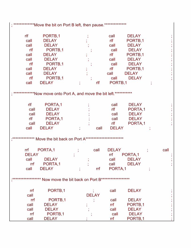
; *************Move the bit on Port B left, then pause.**************
rlf PORTB,1 ; call DELAY ; call DELAY ; rlf PORTB,1 ; call DELAY ; call DELAY ; rlf PORTB,1 ; call DELAY ; call DELAY ; rlf PORTB,1 ; call DELAY ; call DELAY ; rlf PORTB,1 ; call DELAY ; call DELAY ; rlf PORTB,1 ; call DELAY ; call DELAY ; rlf PORTB,1 ; call DELAY ; call DELAY ; rlf PORTB,1 ;
; *************Now move onto Port A, and move the bit left.***********
rlf PORTA,1 ; call DELAY ; call DELAY ; rlf PORTA,1 ; call DELAY ; call DELAY ; rlf PORTA,1 ; call DELAY ; call DELAY ; rlf PORTA,1 ; call DELAY ; call DELAY ;
;************** Move the bit back on Port A************************
rrf PORTA,1 ; call DELAY ; call DELAY ; rrf PORTA,1 ; call DELAY ; call DELAY ; rrf PORTA,1 ; call DELAY ; call DELAY ; rrf PORTA,1 ;
;****************** Now move the bit back on Port B******************
rrf PORTB,1 ; call DELAY ; call DELAY ; rrf PORTB,1 ; call DELAY ; call DELAY ; rrf PORTB,1 ; call DELAY ; call DELAY ; rrf PORTB,1 ; call DELAY ; call DELAY ; rrf PORTB,1 ;
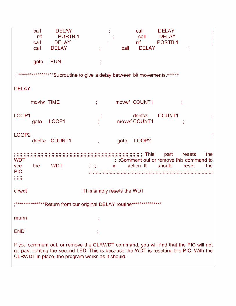
call DELAY ; call DELAY ; rrf PORTB,1 ; call DELAY ; call DELAY ; rrf PORTB,1 ; call DELAY ; call DELAY ;
goto RUN ;
; ******************Subroutine to give a delay between bit movements.******
DELAY
movlw TIME ; movwf COUNT1 ;
LOOP1 ; decfsz COUNT1 ; goto LOOP1 ; movwf COUNT1 ;
LOOP2 ; decfsz COUNT1 ; goto LOOP2
;;;;;;;;;;;;;;;;;;;;;;;;;;;;;;;;;;;;;;;;;;;;;;;;;;;;;;;;;;;;;;;;;;;;;;;;;;;;;;;;;;;;;;;;;; ;; This part resets the WDT ;; ;;Comment out or remove this command to see the WDT ;; ;; in action. It should reset the PIC ;; ;;;;;;;;;;;;;;;;;;;;;;;;;;;;;;;;;;;;;;;;;;;;;;;;;;;;;;;;;;;;;;;;;;;;;;;;;;;;;;;;;;;;;;;;;;;;;
clrwdt ;This simply resets the WDT.
;***************Return from our original DELAY routine***************
return ;
END ;
If you comment out, or remove the CLRWDT command, you will find that the PIC will not go past lighting the second LED. This is because the WDT is resetting the PIC. With the CLRWDT in place, the program works as it should.


![Interrupt Priorities Soþuare via Interrupt - USENIX · Setting Interrupt Priorities in Soþuare via Interrupt Queueing Geoff Collyer Bell Laboratories ... [Kernighan & Ritchie 1978]](https://img.pdfslide.us/doc/110x75/5c8a77bf09d3f22e408bf5b1/interrupt-priorities-sobuare-via-interrupt-usenix-setting-interrupt-priorities.jpg)