Embed Size (px)
Citation preview
Z. Phys. A 356, 263—279 (1996)
Interpretation and quality of the tilted axis cranking approximation
Stefan Frauendorf 1, Jie Meng1,2,*
1 Institut fur Kern- und Hadronenphysik, Forschungszentrum Rossendorf e. V., Postfach 510119, D-01314 Dresden, Germany2 Institute of Theoretical Physics, Chinese Academy of Science, Beijing 100080, People’s Republic of China
Received: 12 June 1996Communicated by B. Herskind
Abstract. Comparing with the exact solutions of themodel system of one and two particles coupled to an axialrotor, the quality of the semi classical tilted axis crankingapproximation is investigated. Extensive comparisons ofthe energies and M1 and E2 transition probabilities arecarried out for the lowest bands. Very good agreement isfound, except near band crossings. Various recipes to takeinto account finite K within the frame of the usual princi-pal axis cranking are included into the comparison. A setof rules is suggested that permits to construct the excitedbands from the cranking configurations, avoiding spu-rious states.
PACS: 21.60.Ev; 21.60.Jz
1 Introduction
Tilted Axis Cranking (TAC) is a systematic microscopicapproach to high spin physics, which provides a semiclassical description of the energies and the intra bandtransition matrix elements for both high-K and low-Kbands. After the existence of tilted solutions for a fixedshape had been demonstrated in [1], the interpretation ofthe solutions has been given in [2, 3], where also thestability of the solutions with respect to deformation hasbeen shown. The method has turned out to be successfulin describing the c-spectra and transition rates of rapidlyrotating nuclei (cf. e.g. [4, 5, 6]). As a complement to thestandard Principal Axis Cranking (PAC) (e.g. [7]), whichdescribes the DI"2 bands with good signature, the TACapproach permits to calculate the DI"1 bands, stayingcompletely within the microscopic mean field approxima-
*Present address: Alexander von Humboldt fellow, Physik-Depart-ment der Technischen Universitat Munchen, D-85747 Garching,Germany
tion. Such bands are quite common in deformed nuclei.The PAC is a special case of the more general TAC.
Cranking mean field theories are based on the classicaltreatment of the total angular momentum and the as-sumption of uniform rotation, which have the conse-quence that angular momentum conservation is violated.The contact with the quantal spectra is made by means ofsemi classical expressions for the energy and transitionmatrix elements. Hence, it seems to be important to inves-tigate how well these approximations work for the de-scription of the experimental observables. There is also theproblem of how to construct the excitation spectrum fromthe TAC quasi particle levels avoiding spurious states. Inorder to study these questions we start from the ParticleRotor Model (PRM) (c.f. e.g. [8]), which treats the quantalangular momentum dynamics correctly. Introducing tothis model the same kind of approximations used for thefully microscopic cranking theory, the TAC version [2] ofthe model system of a rotor core coupled to a few particlesis derived. Comparing the exact PRM solution with theTAC calculations, the quality of the approximation isstudied. We study the cases of one and two quasi particlesin a j-shell coupled to the axial rotor. These are simpleenough to find the exact PRM solution numericallyand permit to model the most important angularmomentum coupling schemes met in rapidly rotatingnuclei. Both energies and intra band transition probabilit-ies are compared. The classification of excited statesand ways to avoid spurious states in the spectrum areaddressed.
The paper is organized as follows: In Sect. 2 webriefly outline the axial PRM for the model systemswe are studying and describe the TAC approximationin the PRM context. The detailed comparisons ofaxial PRM and TAC calculations for the yrast bandsare given in Sect. 3. There, also the construction ofthe excitation spectrum is discussed and the excitedbands of the PRM and TAC are compared. In Sect.4 previous descriptions of high-K bands using the PACscheme [9, 10, 12] are compared with the PRM and theTAC.
2 Formulation of the models
2.1 ¹wo quasi particles in a single j-shell coupledto an axial symmetric rotor
The PRM Hamiltonian [8] is given by
H"h#H30503
, h"hp#h
n. (1)
For convenience we will call one particle a proton (p) andthe other a neutron (n). The formalism is exactly the samefor two protons or neutrons in different j-shells. The caseof two equivalent particles is also covered by the expres-sions below, however the Pauli principle must be takeninto account in constructing the PRM basis states and theTAC configurations.
Expressing the angular momentum of the rotor by thetotal angular momentum Il and the angular momentum j
vof the extra particles,
Rl"Il!jl , jl"jlp#jln (2)
the axial rotor Hamiltonian reads
H30503
" +l/1,2
(Il!jl )22J
, (3)
where J is the moment of inertia of the rotor and thesymmetry axis is chosen to be 3. The j-shell single particleHamiltonians, denoted by h
por h
n, are
hp (n)
"$12
Cp (n)
j23p (n)
, (4)
where the upper sign refers to a particle and the lower oneto a hole. The parameter C
p (n)controls the level splitting in
the deformed field. Pairing is treated by means of theBCS-quasiparticle Hamiltonians
hp (n)
"J(12Cp (n)
j23p (n)
!p (n)
)2#D2p (n)
. (5)
The parameters jp (n)
and Dp(n)
are the chemical potentialand pairing gap, respectively. The modification of theangular momentum matrix elements by pairing is nottaken into account, since it does not lead to any importantchanges. For the same reason the Coriolis matrix elementsare not attenuated. Of course, these simplifications areconsistently applied to both the PRM and the TAC,derived below.
The PRM Hamiltonian is diagonalized in the stan-dard basis Dk
pknIMKT, where DIMKT is the Wigner D-
function and DkpknT is the product of the j-shell states D jkT.
The angular momentum projections onto the quantiz-ation axis (3-) are denoted by k. The eigenstates are writ-ten as states of good signature, i.e.
DIMT"S1
2(1#dK0
)+k
p, k
ncIk
p, k
n[ Dk
pknIMKT
#(!1)I D!kp!k
nIM!KT], (6)
where K"kp#k
nand ck
p,k
nare the expansion coefficients
(see [8] for the details). The full recoil term is included intothe diagonalization.
The B (M1) values are given by
B (M1, IPI@)"3
4nD+k, k
p, k
n, k@
p, k@
ncI{k{
p, k{
ncIk
p, k
n(7)
]SI@K@1k D IKTSk@pk@nD (g
p!g
R) j
pk#(g
n!g
R) j
nk D kpknTD2 ,
where j is written as a spherical tensor of rank 1,
jk"Aj0"j3, j
$1"G( j
1$ij
2)
J2 B . (8)
Since we are only interested in a comparison of TAC withPRM, we set Dg
p (n)!g
RD"1, choosing the signs such that
large B (M1) values are obtained. The B (E2) values arecalculated by means of the expression
B (E2)"5
16n K +kp, k
n
cI{kp, k
ncIk
p, k
nSI@K20 D IKTK
2, (9)
setting the square of the intrinsic electric quadrupolemoment equal to one.
The case of one quasi particle coupled to the rotor isstraightforwardly derived from the formulae above bydropping one particle.
2.2 The TAC approximation
In order to obtain the TAC approximation to the axialPRM we assume:
1. The operator I of the total angular momentum isreplaced by the classical vector J
2. S j2T"S jT2
3. J3"S j
3T, J
2"0, J
1"JJ2!J2
3
Assumption 1) expresses the semi classical character ofthe TAC approximation and assumption 2) its mean fieldcharacter. The relations 3) are consequences of the axialsymmetry: There is no collective angular momentum in3-direction. The classical vector J can always be chosensuch that its second component is equal to zero. Theabsolute value of the classical angular momentum is de-noted by J.
With these assumptions the PRM energy becomes
E"ShT#1
2J[J2!i2
3!2i
1JJ2!i2
3#i2
1#i2
2], (10)
where we have introduced the expectation values il"S jlT of the particle angular momenta (alignments). Theexpectation values are taken with respect to the productwave function
DT"DpTDnT"+kp
ckpDk
pT+
kn
cknDk
nT . (11)
The variation dE"0 for fixed J with respect to theamplitudes c
k(quasi particle wave functions) leads to the
264
eigenvalue problem
Ah#1
J[!i
3j3!(JJ2!i2
3#i
1) j
1#
i1i3
JJ2!i23
j3
#i2j2]B DT"e@DT . (12)
This equation can be written as
h@ DT"e@ DT, h@"h!x · j (13)
with the definition of the angular velocity x
x"AJJ2!i23!i
1, 0, i
3!
i1i3
JJ2!i23BNJ. (14)
The choice u2"0 implies that i
2"0, in accordance with
assumption 3). Thus, the variational problem (12) is equiv-alent with the TAC eigenvalue problem (13) and the twoself consistency eqs. (14) for the angular velocity. Thesecan be rewritten as
u1
u3
"
J1(1!i
1/J
1)
J3(1!i
1/J
1)"
J1
J3
,tan 0 (15)
and
J"i1
sin0#uJ. (16)
Eq. (15) is the TAC condition [2, 3, 4] that x and J mustbe parallel at the point of self consistency (energy min-imum). It fixes the tilt angle 0, which is the angle of totalangular momentum J with the 3-axis. Equation (16) pro-vides the relation between u and J.
Thus, it is shown that the assumptions 1) and 2) leadin fact to the TAC version [2] that approximates thePRM. Let us represent it in the same way as full mean fieldTAC [3, 4] is formulated. The quasi particle states arefound by diagonalization of the qp. Routhian
h@"h!u3j3!u
1j1"h!u(sin 0 j
1#cos0 j
3) (17)
The tilt angle is determined by making x parallel to J.This is equivalent with minimizing the total Routhian
E@"Sh@T!12J(u sin0 )2 (18)
with respect to 0 at fixed u. The expectation value of thetotal angular momentum in the intrinsic frame system isgiven by the expressions
J1"i
1#sin0uJ, J
3"i
3, J"JJ2
1#J2
3. (19)
The total energy E (lab. frame) and the total Routhian E @(rotating frame) are related by the standard canonical eqs.
E"E @#uJ ,dE
dJ"u,
dE @du
"!J. (20)
Naturally, the TAC expressions derived from PRM con-tain a core contribution in addition to the quasi particlepart, whereas in the full TAC all energy and angularmomentum comes from the quasi particles. The PRMversion of TAC is discussed in detail in [2].
2.3 Relation of TAC to the rotational states
Before comparing the smooth functions J (u), E (J),2obtained in TAC with the discrete values I, E(I),2 cal-culated in the PRM, the relationship between the classicalTAC quantities and the quantal PRM quantities must beestablished. One must distinguish between two cases:
1. TAC solution DuT: The energy minimum lies ata tilt angle 0 that is different from 0° or 90°. Thesignature symmetry is broken and the quasi particleconfiguration is wave packet composed of allpossible I-states. It is associated with a DI"1rotational band of parity n, whose states areinter-connected by strong M1 and E2 transitions.
2. PAC solution Da,uT: The energy minimum lies atthe tilt angle 0"90°. The signature a is a goodquantum number and the quasi particle configura-tion is wave packet composed of all possible I"amod 2 states. It is associated with a DI"2 rota-tional band of parity n and spin I"a mod 2, whosestates are inter-connected by strong E2-transitions.
This distinction is a consequence of the mean field approx-imation. The two types of solutions with different sym-metry have to be interpreted differently, leading to wellknown problems for the transitional cases. The gradualappearance of signature splitting along a band cannot bedescribed by the TAC. This question will be discussed inmore detail below.
In order to include the lowest order quantal correctionthe spin I of the PRM must be associated with the angularmomentum J (u)!1/2 of TAC [8, 10]. For example, E (I)of the PRM is compared with E (J"I#1/2) calculated inTAC. The inclusion of this quantal correction consider-ably improves the agreement between PRM and TAC.
Analyzing the experiments it is often useful to trans-form the quantal values of energy and spin to the fre-quency u and the Routhians E @ of the cranking theory[10]. We will do the same with our PRM results. In thecase of a DI"1 band we use
J"I, u"E (I )!E (I!1),
E@"12[E(I)#E(I!1)]!uJ. (21)
Due to the quantal correction one must associate J withI#1
2, while the rotational frequency u is the transition
energy from I to I!1 corresponding to the mean valueI!1
2. Hence, the angular momentum J of the transition is
given by I, the upper spin value.For DI"2 bands with signature splitting we use
J"I!12, u"1
2[E (I)!E(I!2)],
E@"12[E(I)#E (I!2)]!uJ. (22)
This corresponds to the prescription of [10], setting K"0(no projection of the angular momentum on the 1-axis).Equations (21) and (22) provide discrete points J (u) andE@(u) that are compared with the corresponding points onthe continuous curves calculated by means of TAC. Insome figs. we shall show continuous functions E@ (u) forthe PRM that are obtained by interpolation from thediscrete points.
265
By semi classical correspondence one finds [2, 3, 12]for the intra band M1-transition strength1
B(M1)"3
8n[sin0 ((g
p!g
R) i3p#(g
n!g
R)i3n
)
!cos0 ((gp!g
R)i1p#(g
n!g
R)i1n
)]2 (23)
The B (M1) value calculated at angular momentum J(u)"I must be compared with B (M1, IPI!1) of the PRM(cf. discussion of the definition of u). The stretched BE(E2)values are given by [2, 4, 12]:2
B(E2)"15
128n(sin0 )4 (24)
The TAC value calculated for J (u)"I!1/2 is comparedto the B (E2, IPI!2) value in the PRM.
The expression (24) for the B (E2) values is applicableboth for TAC and PAC solutions. The expression (23) forthe B (M1) values gives 0 for PAC solutions, because thetransversal component of the magnetic vector is zero forsymmetry reasons. In this case the two branches of theband among which the magnetic transition takes placemust be interpreted as two intrinsic configurations withopposite signature. The B(M1) value is then given by theexpression suggested by Hamamoto and Sagawa [14]3
B(M1)"3
4nS1 D (gq!g
R) j
$1, q D 2T2, (25)
where q is p or n depending on whether the proton or theneutron changes its configuration and j
$1 are the spheri-cal components defined by (8), but with respect to the1-axis.
3 Comparison of the PRM and TAC
Particles, holes and quasi particles in the h11@2
shell arestudied as examples. Different coupling schemes are con-sidered, which correspond to different choices of the con-stant C in the single particle Hamiltonian (4). We considertwo values, DC D"0.25MeV and 0.10MeV correspondingto a well deformed and weakly deformed nucleus (b+0.25 and 0.1), respectively. Let us adopt the classificationof coupling schemes suggested in [15]. For prolate shape,the value C"0.25 MeV corresponds to a particle at thebottom of the shell, which becomes very easily rotationalaligned (RAL-rotational aligned). The value C"!0.25MeV corresponds to a hole at the top of the shell, which isaligned with the symmetry axis of the deformed field(DAL-deformation aligned). For oblate shape the particle
1Deriving (23) from the microscopic expression (14) of [3], onesingles out the contributions of the valence particles and defines therest as the core contribution. Introducing l
p"g
pip, l
n"g
nin,
lR"g
RR and using that R"J!i
p!i
nimplies R
M"!(i
p#i
n)M,
(23) is obtained2 [4] contains an unfortunate misprint, missing a factor of 1/43The expression l
n$1"(gq!gR) j
$1, q used for the magnetic mo-ment operator accounts for the conservation of angular momentum.It can easily be guessed from the quantal expressions given in [8]
and the hole change their roles. A mid-shell quasi particle(k+7/2) is modeled by the quasi particle Hamiltonian (5)with C"0.25MeV, D"0.8MeV and j"2 MeV. It cor-responds to a coupling that prefers an angle of about 45°with respect to the 3-axis (FAL-Fermi aligned). In prin-ciple the same classification applies for the small deforma-tion. However, the rotation perturbs the idealized schemesconsiderably.
To be realistic, the core moment of inertia is chosen tobe J"30 and 15MeV~1 for the large and the smalldeformation, respectively. The agreement between TACand PRM, discussed below, is not sensitive to the valueof J. In order to make small energy differences bettervisible, the term !hu2/2, with h"30MeV~1 (rigid rotorRouthian) is subtracted from both the TAC and the PRMRouthians shown in Figs. 14, 15 and 16. It represents justa shift of all energies by the same amount and h must notbe confused with the moment of inertia J of the PRM.
3.1 One particle or hole
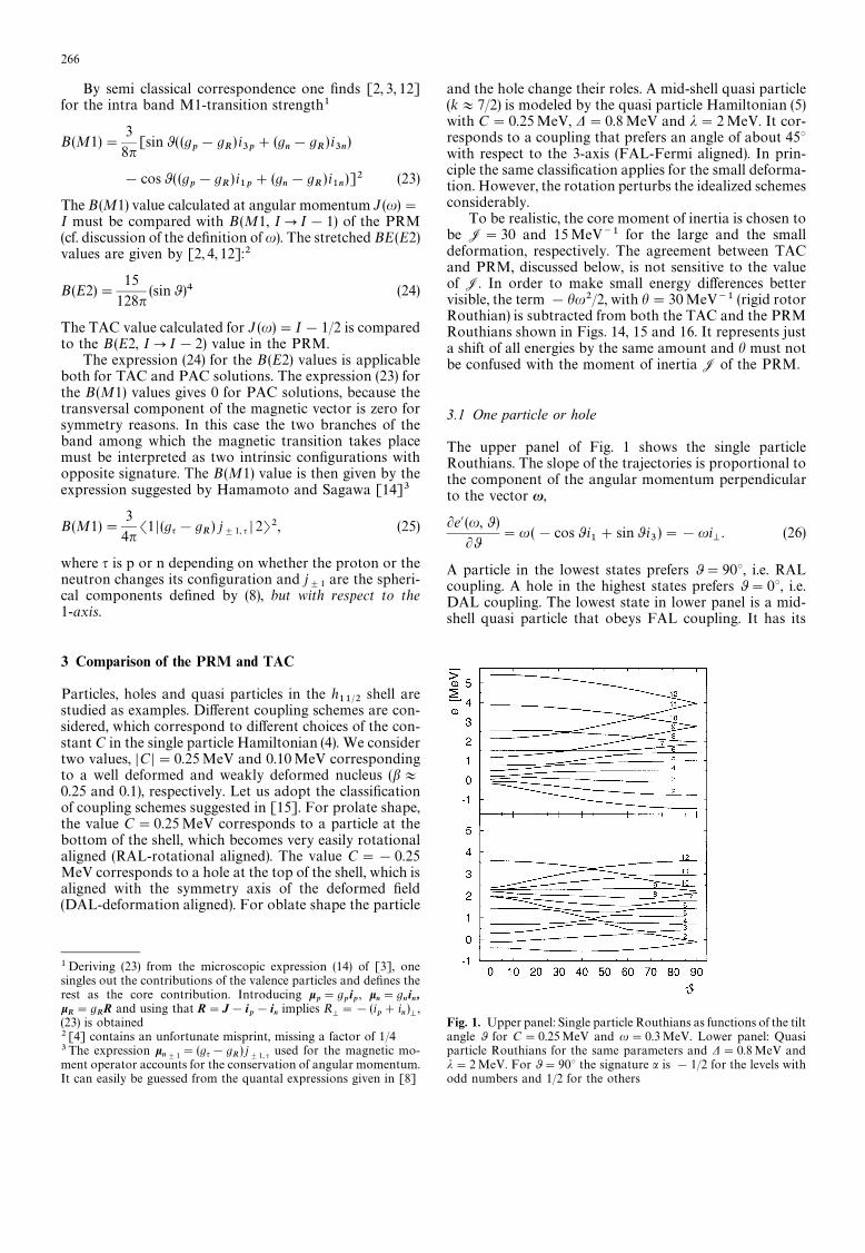
The upper panel of Fig. 1 shows the single particleRouthians. The slope of the trajectories is proportional tothe component of the angular momentum perpendicularto the vector x,
Le@(u, 0 )
L0"u(!cos 0 i
1#sin0 i
3)"!ui
M. (26)
A particle in the lowest states prefers 0"90°, i.e. RALcoupling. A hole in the highest states prefers 0"0°, i.e.DAL coupling. The lowest state in lower panel is a mid-shell quasi particle that obeys FAL coupling. It has its
Fig. 1. Upper panel: Single particle Routhians as functions of the tiltangle 0 for C"0.25MeV and u"0.3MeV. Lower panel: Quasiparticle Routhians for the same parameters and D"0.8MeV andj"2 MeV. For 0"90° the signature a is !1/2 for the levels withodd numbers and 1/2 for the others
266
minimum around 0"45°. Since the curve is rather flat,iM
is relatively small, i.e. the FAL quasi particles tend toalign with x.
In addition to the particle energies, the total RouthianE@(0 ) in (18) contains the core term !1
2J(u sin 0)2,
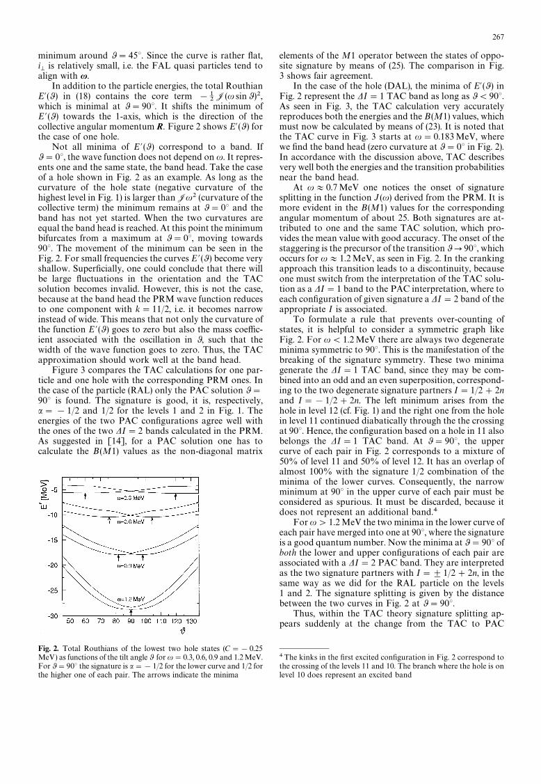
which is minimal at 0"90°. It shifts the minimum ofE @ (0) towards the 1-axis, which is the direction of thecollective angular momentum R. Figure 2 shows E@(0 ) forthe case of one hole.
Not all minima of E @ (0 ) correspond to a band. If0"0°, the wave function does not depend on u. It repres-ents one and the same state, the band head. Take the caseof a hole shown in Fig. 2 as an example. As long as thecurvature of the hole state (negative curvature of thehighest level in Fig. 1) is larger thanJu2 (curvature of thecollective term) the minimum remains at 0"0° and theband has not yet started. When the two curvatures areequal the band head is reached. At this point the minimumbifurcates from a maximum at 0"0°, moving towards90°. The movement of the minimum can be seen in theFig. 2. For small frequencies the curves E @ (0 ) become veryshallow. Superficially, one could conclude that there willbe large fluctuations in the orientation and the TACsolution becomes invalid. However, this is not the case,because at the band head the PRM wave function reducesto one component with k"11/2, i.e. it becomes narrowinstead of wide. This means that not only the curvature ofthe function E @(0) goes to zero but also the mass coeffic-ient associated with the oscillation in 0, such that thewidth of the wave function goes to zero. Thus, the TACapproximation should work well at the band head.
Figure 3 compares the TAC calculations for one par-ticle and one hole with the corresponding PRM ones. Inthe case of the particle (RAL) only the PAC solution 0"90° is found. The signature is good, it is, respectively,a"!1/2 and 1/2 for the levels 1 and 2 in Fig. 1. Theenergies of the two PAC configurations agree well withthe ones of the two DI"2 bands calculated in the PRM.As suggested in [14], for a PAC solution one has tocalculate the B (M1) values as the non-diagonal matrix
Fig. 2. Total Routhians of the lowest two hole states (C"!0.25MeV) as functions of the tilt angle 0 for u"0.3, 0.6, 0.9 and 1.2MeV.For 0"90° the signature is a"!1/2 for the lower curve and 1/2 forthe higher one of each pair. The arrows indicate the minima
elements of the M1 operator between the states of oppo-site signature by means of (25). The comparison in Fig.3 shows fair agreement.
In the case of the hole (DAL), the minima of E@(0 ) inFig. 2 represent the DI"1 TAC band as long as 0(90°.As seen in Fig. 3, the TAC calculation very accuratelyreproduces both the energies and the B (M1) values, whichmust now be calculated by means of (23). It is noted thatthe TAC curve in Fig. 3 starts at u"0.183MeV, wherewe find the band head (zero curvature at 0"0° in Fig. 2).In accordance with the discussion above, TAC describesvery well both the energies and the transition probabilitiesnear the band head.
At u+0.7MeV one notices the onset of signaturesplitting in the function J (u) derived from the PRM. It ismore evident in the B (M1) values for the correspondingangular momentum of about 25. Both signatures are at-tributed to one and the same TAC solution, which pro-vides the mean value with good accuracy. The onset of thestaggering is the precursor of the transition 0P90°, whichoccurs for u+1.2MeV, as seen in Fig. 2. In the crankingapproach this transition leads to a discontinuity, becauseone must switch from the interpretation of the TAC solu-tion as a DI"1 band to the PAC interpretation, where toeach configuration of given signature a DI"2 band of theappropriate I is associated.
To formulate a rule that prevents over-counting ofstates, it is helpful to consider a symmetric graph likeFig. 2. For u(1.2MeV there are always two degenerateminima symmetric to 90°. This is the manifestation of thebreaking of the signature symmetry. These two minimagenerate the DI"1 TAC band, since they may be com-bined into an odd and an even superposition, correspond-ing to the two degenerate signature partners I"1/2#2nand I"!1/2#2n. The left minimum arises from thehole in level 12 (cf. Fig. 1) and the right one from the holein level 11 continued diabatically through the the crossingat 90°. Hence, the configuration based on a hole in 11 alsobelongs the DI"1 TAC band. At 0"90°, the uppercurve of each pair in Fig. 2 corresponds to a mixture of50% of level 11 and 50% of level 12. It has an overlap ofalmost 100% with the signature 1/2 combination of theminima of the lower curves. Consequently, the narrowminimum at 90° in the upper curve of each pair must beconsidered as spurious. It must be discarded, because itdoes not represent an additional band.4
For u'1.2MeV the two minima in the lower curve ofeach pair have merged into one at 90°, where the signatureis a good quantum number. Now the minima at 0"90° ofboth the lower and upper configurations of each pair areassociated with a DI"2 PAC band. They are interpretedas the two signature partners with I"$1/2#2n, in thesame way as we did for the RAL particle on the levels1 and 2. The signature splitting is given by the distancebetween the two curves in Fig. 2 at 0"90°.
Thus, within the TAC theory signature splitting ap-pears suddenly at the change from the TAC to PAC
4The kinks in the first excited configuration in Fig. 2 correspond tothe crossing of the levels 11 and 10. The branch where the hole is onlevel 10 does represent an excited band
267

Fig. 3. Energy, angular momentum and B (M1) values of the lowestbands for a particle and a hole coupled to the rotor. Circles: PRM-hole, squares: PRM-particle, full line: TAC-hole, dashed line: PAC-
particle. The dashed dotted curve is calculated by means of (37),combining the tilted geometry with the PAC calculation
interpretation. TAC only describes the two limiting casesof no or substantial splitting, the gradual onset cannotbe accounted for. Around u"0.9MeV or angular mo-mentum 30 one must switch from the TAC interpretationwithout signature effects to the PAC interpretation withfinite signature effects. The pair of curves for u"0.9MeVcan be interpreted in two ways: Either the two minima at82° and 98° generate the lowest DI"1 band. Then thenarrow minimum at 0"90° of the higher of the twocurves must be discarded. Or the minimum and the max-imum at 0"90° are interpreted as the two signaturebranches. As seen in Fig. 3 the best match of the B(M1)values is achieved if one changes from the TAC to thePAC interpretation near u"0.9MeV, somewhat beforethe two minima in the lower curve have merged. This canbe attributed to the zero point fluctuations.
The signature splitting of the energies is barely visiblein Fig. 3. For the FAL quasiparticle, discussed next, onealso encounters a noticeable discontinuity in the energies.
3.2 One mid-shell quasi particle
Figure 4 illustrates the case of a quasi particle in themiddle of the shell, where pairing must be taken intoaccount. The chemical potential lies between the 7/2 and9/2 level. The configuration corresponds to a FAL quasi
particle on the lowest level in lower panel of Fig. 1. Wedefine the band head from the criterion that in a band theenergy must increase with I. For the PRM yrast energiesthis is the case from the 11/2P9/2 transition on. Thecorresponding frequency u"0.05MeV agrees well withthe lowest value of u for which we find a TAC solution. Atthe band head there is a rapid change from DAL couplingto the FAL coupling. Though the agreement is not perfect,the TAC is still a good approximation near the band head.At u"0.7MeV and I"25 the tilt angle 0 reaches 90°.The change from the TAC interpretation to the PACscheme with signature splitting leads to a more pro-nounced discontinuity in the energies than for the case ofone hole discussed above. Up to about spin 18 the TACsolution describes the signature average of the energy andof the B(M1) values well. Above spin 25 the PAC solutionbecomes a good approximation. Again, the best possiblematch is achieved around spin 20, somewhat below wherethe two TAC minima merge into the PAC minimum.
3.3 Yrast band of two holes
The coupling of a DAL proton hole and a DAL neutronhole (both in level 12 of Fig. 1) to the rotor is illustrated inFig. 5. As seen in Fig. 6, the TAC reproduces the PRMenergies and transition probabilities very well. The growth
268
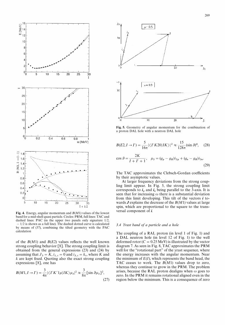
Fig. 4. Energy, angular momentum and B (M1) values of the lowestband for a mid-shell quasi particle. Circles: PRM, full lines: TAC anddashed lines: PAC (in the upper two panels only signature 1/2,!1/2 is shown as a full line). The dashed dotted curve is calculatedby means of (37), combining the tilted geometry with the PACcalculation
of the B (M1) and B (E2) values reflects the well knownstrong coupling behavior [8]. The strong coupling limit isobtained from the general expressions (23) and (24) byassuming that J
3"K, i
1, q"0 and i3,q"kq , where K and
k are kept fixed. Quoting also the exact strong couplingexpressions [8], one has
B(M1, IPI@ )"3
4nDSI@K @1kDIKTk
3D2+
3
8n[sin0k
3]2,
(27)
Fig. 5. Geometry of angular momentum for the combination ofa proton DAL hole with a neutron DAL hole
B (E2, IPI@)"5
16nDSI@K20 DIKTD2+
15
128n(sin0 )4, (28)
cos0"2K
I#I@#1, k
3"(g
p!g
R)i3p#(g
n!g
R) i3n
.
(29)
The TAC approximates the Clebsch-Gordan coefficientsby their asymptotic values.
At larger frequency deviations from the strong coup-ling limit appear. In Fig. 5, the strong coupling limitcorresponds to i
pand i
nbeing parallel to the 3-axis. It is
seen that for increasing u there is a substantial deviationfrom this limit developing. This tilt of the vectors i to-wards J explains the decrease of the B(M1) values at largespin, which are proportional to the square to the trans-versal component of i.
3.4 Yrast band of a particle and a hole
The coupling of a RAL proton (in level 1 of Fig. 1) anda DAL neutron hole (in level 12 of Fig. 1) to the welldeformed rotor (C"0.25MeV) is illustrated by the vectordiagram 7. As seen in Fig. 8, TAC approximates the PRMwell for the ‘‘rotational part’’ of the yrast sequence, wherethe energy increases with the angular momentum. Nearthe minimum of E (I), which represents the band head, theTAC ceases to work. The B (M1) values drop to zero,whereas they continue to grow in the PRM. The problemarises, because the RAL proton dealigns when u goes tozero. In the PRM it remains rotational aligned even in theregion below the minimum. This is a consequence of zero
269
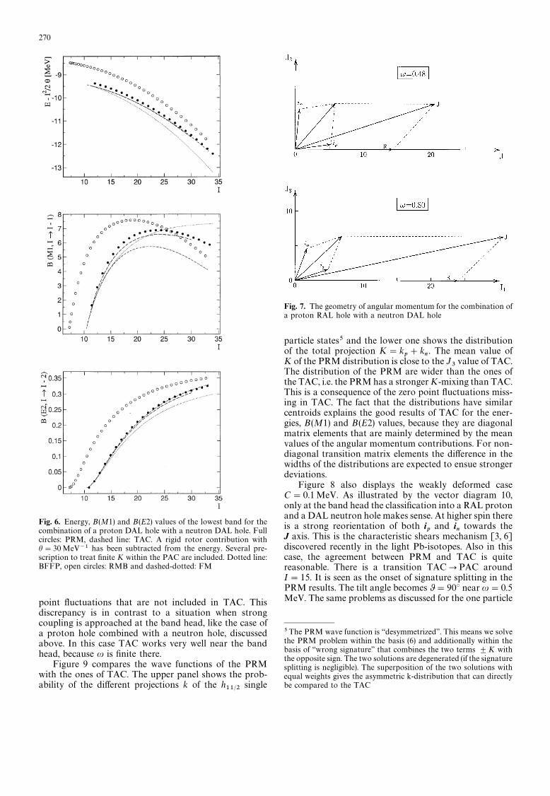
Fig. 6. Energy, B(M1) and B(E2) values of the lowest band for thecombination of a proton DAL hole with a neutron DAL hole. Fullcircles: PRM, dashed line: TAC. A rigid rotor contribution withh"30 MeV~1 has been subtracted from the energy. Several pre-scription to treat finite K within the PAC are included. Dotted line:BFFP, open circles: RMB and dashed-dotted: FM
point fluctuations that are not included in TAC. Thisdiscrepancy is in contrast to a situation when strongcoupling is approached at the band head, like the case ofa proton hole combined with a neutron hole, discussedabove. In this case TAC works very well near the bandhead, because u is finite there.
Figure 9 compares the wave functions of the PRMwith the ones of TAC. The upper panel shows the prob-ability of the different projections k of the h
11@2single
Fig. 7. The geometry of angular momentum for the combination ofa proton RAL hole with a neutron DAL hole
particle states5 and the lower one shows the distributionof the total projection K"k
p#k
n. The mean value of
K of the PRM distribution is close to the J3value of TAC.
The distribution of the PRM are wider than the ones ofthe TAC, i.e. the PRM has a stronger K-mixing than TAC.This is a consequence of the zero point fluctuations miss-ing in TAC. The fact that the distributions have similarcentroids explains the good results of TAC for the ener-gies, B (M1) and B (E2) values, because they are diagonalmatrix elements that are mainly determined by the meanvalues of the angular momentum contributions. For non-diagonal transition matrix elements the difference in thewidths of the distributions are expected to ensue strongerdeviations.
Figure 8 also displays the weakly deformed caseC"0.1MeV. As illustrated by the vector diagram 10,only at the band head the classification into a RAL protonand a DAL neutron hole makes sense. At higher spin thereis a strong reorientation of both i
pand i
ntowards the
J axis. This is the characteristic shears mechanism [3, 6]discovered recently in the light Pb-isotopes. Also in thiscase, the agreement between PRM and TAC is quitereasonable. There is a transition TACPPAC aroundI"15. It is seen as the onset of signature splitting in thePRM results. The tilt angle becomes 0"90° near u"0.5MeV. The same problems as discussed for the one particle
5The PRM wave function is ‘‘desymmetrized’’. This means we solvethe PRM problem within the basis (6) and additionally within thebasis of ‘‘wrong signature’’ that combines the two terms $K withthe opposite sign. The two solutions are degenerated (if the signaturesplitting is negligible). The superposition of the two solutions withequal weights gives the asymmetric k-distribution that can directlybe compared to the TAC
270
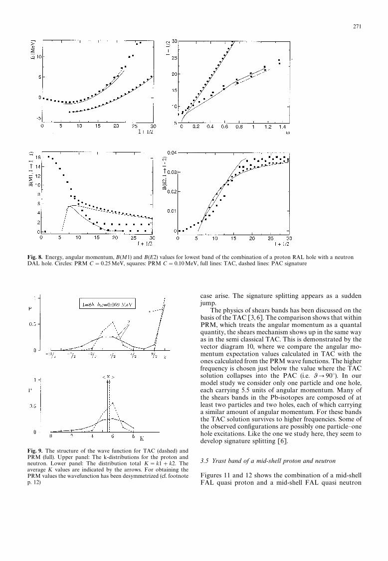
Fig. 8. Energy, angular momentum, B(M1) and B(E2) values for lowest band of the combination of a proton RAL hole with a neutronDAL hole. Circles: PRM C"0.25MeV, squares: PRM C"0.10MeV, full lines: TAC, dashed lines: PAC signature
Fig. 9. The structure of the wave function for TAC (dashed) andPRM (full). Upper panel: The k-distributions for the proton andneutron. Lower panel: The distribution total K"k1#k2. Theaverage K values are indicated by the arrows. For obtaining thePRM values the wavefunction has been desymmetrized (cf. footnotep. 12)
case arise. The signature splitting appears as a suddenjump.
The physics of shears bands has been discussed on thebasis of the TAC [3, 6]. The comparison shows that withinPRM, which treats the angular momentum as a quantalquantity, the shears mechanism shows up in the same wayas in the semi classical TAC. This is demonstrated by thevector diagram 10, where we compare the angular mo-mentum expectation values calculated in TAC with theones calculated from the PRM wave functions. The higherfrequency is chosen just below the value where the TACsolution collapses into the PAC (i.e. 0P90°). In ourmodel study we consider only one particle and one hole,each carrying 5.5 units of angular momentum. Many ofthe shears bands in the Pb-isotopes are composed of atleast two particles and two holes, each of which carryinga similar amount of angular momentum. For these bandsthe TAC solution survives to higher frequencies. Some ofthe observed configurations are possibly one particle—onehole excitations. Like the one we study here, they seem todevelop signature splitting [6].
3.5 Yrast band of a mid-shell proton and neutron
Figures 11 and 12 shows the combination of a mid-shellFAL quasi proton and a mid-shell FAL quasi neutron
271
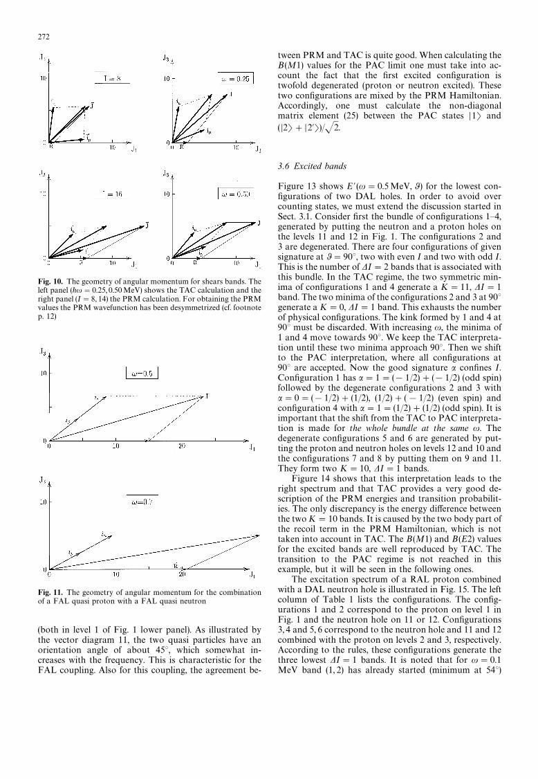
Fig. 10. The geometry of angular momentum for shears bands. Theleft panel (+u"0.25, 0.50MeV) shows the TAC calculation and theright panel (I"8, 14) the PRM calculation. For obtaining the PRMvalues the PRM wavefunction has been desymmetrized (cf. footnotep. 12)
Fig. 11. The geometry of angular momentum for the combinationof a FAL quasi proton with a FAL quasi neutron
(both in level 1 of Fig. 1 lower panel). As illustrated bythe vector diagram 11, the two quasi particles have anorientation angle of about 45°, which somewhat in-creases with the frequency. This is characteristic for theFAL coupling. Also for this coupling, the agreement be-
tween PRM and TAC is quite good. When calculating theB (M1) values for the PAC limit one must take into ac-count the fact that the first excited configuration istwofold degenerated (proton or neutron excited). Thesetwo configurations are mixed by the PRM Hamiltonian.Accordingly, one must calculate the non-diagonalmatrix element (25) between the PAC states D1T and( D2T#D2@T)/J2.
3.6 Excited bands
Figure 13 shows E @ (u"0.5MeV, 0 ) for the lowest con-figurations of two DAL holes. In order to avoid overcounting states, we must extend the discussion started inSect. 3.1. Consider first the bundle of configurations 1—4,generated by putting the neutron and a proton holes onthe levels 11 and 12 in Fig. 1. The configurations 2 and3 are degenerated. There are four configurations of givensignature at 0"90°, two with even I and two with odd I.This is the number of DI"2 bands that is associated withthis bundle. In the TAC regime, the two symmetric min-ima of configurations 1 and 4 generate a K"11, DI"1band. The two minima of the configurations 2 and 3 at 90°generate a K"0, DI"1 band. This exhausts the numberof physical configurations. The kink formed by 1 and 4 at90° must be discarded. With increasing u, the minima of1 and 4 move towards 90°. We keep the TAC interpreta-tion until these two minima approach 90°. Then we shiftto the PAC interpretation, where all configurations at90° are accepted. Now the good signature a confines I.Configuration 1 has a"1"(!1/2)#(!1/2) (odd spin)followed by the degenerate configurations 2 and 3 witha"0"(!1/2)#(1/2), (1/2)#(!1/2) (even spin) andconfiguration 4 with a"1"(1/2)#(1/2) (odd spin). It isimportant that the shift from the TAC to PAC interpreta-tion is made for the whole bundle at the same u. Thedegenerate configurations 5 and 6 are generated by put-ting the proton and neutron holes on levels 12 and 10 andthe configurations 7 and 8 by putting them on 9 and 11.They form two K"10, DI"1 bands.
Figure 14 shows that this interpretation leads to theright spectrum and that TAC provides a very good de-scription of the PRM energies and transition probabilit-ies. The only discrepancy is the energy difference betweenthe two K"10 bands. It is caused by the two body part ofthe recoil term in the PRM Hamiltonian, which is nottaken into account in TAC. The B (M1) and B (E2) valuesfor the excited bands are well reproduced by TAC. Thetransition to the PAC regime is not reached in thisexample, but it will be seen in the following ones.
The excitation spectrum of a RAL proton combinedwith a DAL neutron hole is illustrated in Fig. 15. The leftcolumn of Table 1 lists the configurations. The config-urations 1 and 2 correspond to the proton on level 1 inFig. 1 and the neutron hole on 11 or 12. Configurations3, 4 and 5, 6 correspond to the neutron hole and 11 and 12combined with the proton on levels 2 and 3, respectively.According to the rules, these configurations generate thethree lowest DI"1 bands. It is noted that for u"0.1MeV band (1, 2) has already started (minimum at 54°)
272
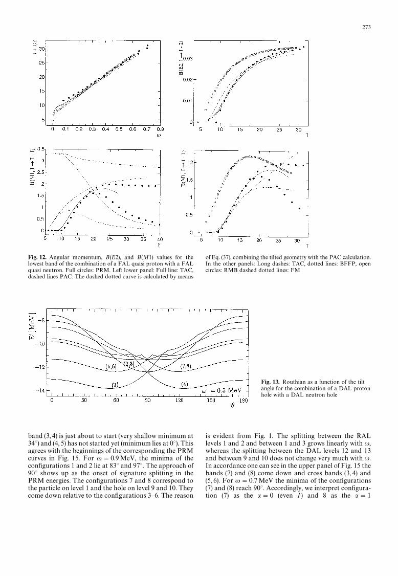
Fig. 12. Angular momentum, B(E2), and B (M1) values for thelowest band of the combination of a FAL quasi proton with a FALquasi neutron. Full circles: PRM. Left lower panel: Full line: TAC,dashed lines PAC. The dashed dotted curve is calculated by means
of Eq. (37), combining the tilted geometry with the PAC calculation.In the other panels: Long dashes: TAC, dotted lines: BFFP, opencircles: RMB dashed dotted lines: FM
Fig. 13. Routhian as a function of the tiltangle for the combination of a DAL protonhole with a DAL neutron hole
band (3, 4) is just about to start (very shallow minimum at34°) and (4, 5) has not started yet (minimum lies at 0°). Thisagrees with the beginnings of the corresponding the PRMcurves in Fig. 15. For u"0.9MeV, the minima of theconfigurations 1 and 2 lie at 83° and 97°. The approach of90° shows up as the onset of signature splitting in thePRM energies. The configurations 7 and 8 correspond tothe particle on level 1 and the hole on level 9 and 10. Theycome down relative to the configurations 3—6. The reason
is evident from Fig. 1. The splitting between the RALlevels 1 and 2 and between 1 and 3 grows linearly with u,whereas the splitting between the DAL levels 12 and 13and between 9 and 10 does not change very much with u.In accordance one can see in the upper panel of Fig. 15 thebands (7) and (8) come down and cross bands (3, 4) and(5, 6). For u"0.7MeV the minima of the configurations(7) and (8) reach 90°. Accordingly, we interpret configura-tion (7) as the a"0 (even I ) and 8 as the a"1
273
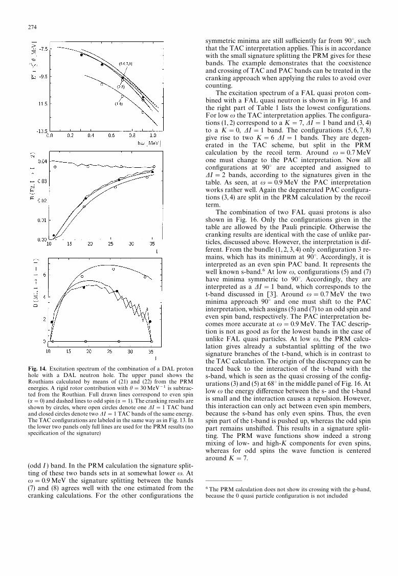
Fig. 14. Excitation spectrum of the combination of a DAL protonhole with a DAL neutron hole. The upper panel shows theRouthians calculated by means of (21) and (22) from the PRMenergies. A rigid rotor contribution with h"30MeV~1 is subtrac-ted from the Routhian. Full drawn lines correspond to even spin(a"0) and dashed lines to odd spin (a"1). The cranking results areshown by circles, where open circles denote one DI"1 TAC bandand closed circles denote two DI"1 TAC bands of the same energy.The TAC configurations are labeled in the same way as in Fig. 13. Inthe lower two panels only full lines are used for the PRM results (nospecification of the signature)
(odd I ) band. In the PRM calculation the signature split-ting of these two bands sets in at somewhat lower u. Atu"0.9MeV the signature splitting between the bands(7) and (8) agrees well with the one estimated from thecranking calculations. For the other configurations the
symmetric minima are still sufficiently far from 90°, suchthat the TAC interpretation applies. This is in accordancewith the small signature splitting the PRM gives for thesebands. The example demonstrates that the coexistenceand crossing of TAC and PAC bands can be treated in thecranking approach when applying the rules to avoid overcounting.
The excitation spectrum of a FAL quasi proton com-bined with a FAL quasi neutron is shown in Fig. 16 andthe right part of Table 1 lists the lowest configurations.For low u the TAC interpretation applies. The configura-tions (1, 2) correspond to a K"7, DI"1 band and (3, 4)to a K"0, DI"1 band. The configurations (5, 6, 7, 8)give rise to two K"6 DI"1 bands. They are degen-erated in the TAC scheme, but split in the PRMcalculation by the recoil term. Around u"0.7MeVone must change to the PAC interpretation. Now allconfigurations at 90° are accepted and assigned toDI"2 bands, according to the signatures given in thetable. As seen, at u"0.9MeV the PAC interpretationworks rather well. Again the degenerated PAC configura-tions (3, 4) are split in the PRM calculation by the recoilterm.
The combination of two FAL quasi protons is alsoshown in Fig. 16. Only the configurations given in thetable are allowed by the Pauli principle. Otherwise thecranking results are identical with the case of unlike par-ticles, discussed above. However, the interpretation is dif-ferent. From the bundle (1, 2, 3, 4) only configuration 3 re-mains, which has its minimum at 90°. Accordingly, it isinterpreted as an even spin PAC band. It represents thewell known s-band.6 At low u, configurations (5) and (7)have minima symmetric to 90°. Accordingly, they areinterpreted as a DI"1 band, which corresponds to thet-band discussed in [3]. Around u"0.7MeV the twominima approach 90° and one must shift to the PACinterpretation, which assigns (5) and (7) to an odd spin andeven spin band, respectively. The PAC interpretation be-comes more accurate at u"0.9MeV. The TAC descrip-tion is not as good as for the lowest bands in the case ofunlike FAL quasi particles. At low u, the PRM calcu-lation gives already a substantial splitting of the twosignature branches of the t-band, which is in contrast tothe TAC calculation. The origin of the discrepancy can betraced back to the interaction of the t-band with thes-band, which is seen as the quasi crossing of the config-urations (3) and (5) at 68° in the middle panel of Fig. 16. Atlow u the energy difference between the s- and the t-bandis small and the interaction causes a repulsion. However,this interaction can only act between even spin members,because the s-band has only even spins. Thus, the evenspin part of the t-band is pushed up, whereas the odd spinpart remains unshifted. This results in a signature split-ting. The PRM wave functions show indeed a strongmixing of low- and high-K components for even spins,whereas for odd spins the wave function is centeredaround K"7.
6The PRM calculation does not show its crossing with the g-band,because the 0 quasi particle configuration is not included
274
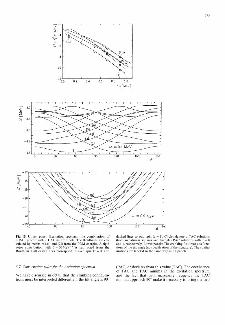
Fig. 15. Upper panel: Excitation spectrum the combination ofa RAL proton with a DAL neutron hole. The Routhians are cal-culated by means of (21) and (22) from the PRM energies. A rigidrotor contribution with h"30MeV~1 is subtracted from theRouthian. Full drawn lines correspond to even spin (a"0) and
dashed lines to odd spin (a"1). Circles denote a TAC solutions(both signatures), squares and triangles PAC solutions with a"0and 1, respectively. Lower panels: The cranking Routhians as func-tions of the tilt angle (no specification of the signature). The config-urations are labeled in the same way in all panels
3.7 Construction rules for the excitation spectrum
We have discussed in detail that the cranking configura-tions must be interpreted differently if the tilt angle is 90°
(PAC) or deviates from this value (TAC). The coexistenceof TAC and PAC minima in the excitation spectrumand the fact that with increasing frequency the TACminima approach 90° make it necessary to bring the two
275
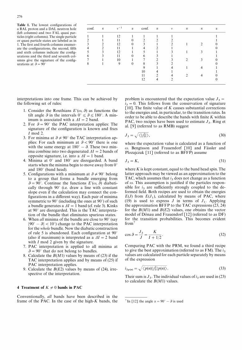
Table 1. The lowest configurations ofa RAL proton and a DAL neutron hole(left columns) and two FAL quasi par-ticles (right columns). The single particleor quasi particle states are labeled as in1. The first and fourth columns enumer-ate the configurations, the second, fifthand sixth columns indicate the config-urations and the third and seventh col-umns give the signature of the config-urations at 0"90°
conf. n l~1 a conf. n l n n a
1 1 12 1 1 1 1 12 1 11 0 2 2 2 13 2 12 0 3 1 2 1 2 04 2 11 1 4 2 1 05 3 12 1 5 1 3 1 3 16 3 11 0 6 3 1 17 1 10 1 7 2 3 2 3 08 1 9 0 8 3 2 0
9 1 4 1 4 110 4 1 111 2 4 2 4 012 4 2 0
interpretations into one frame. This can be achieved bythe following set of rules:
1. Consider the Routhians E @(u, 0) as functions thetilt angle 0 in the intervals 0°404180°. A min-imum is associated with a DI"2 band.
2. For 0"90° the PAC interpretation applies: Thesignature of the configuration is known and fixesI mod 2.
3. For minima at 0O90° the TAC interpretation ap-plies: For each minimum at 0(90° there is onewith the same energy at 180°!0. These two min-ima combine into two degenerated DI"2 bands ofopposite signature, i.e. into a DI"1 band.
4. Minima at 0° and 180° are disregarded. A bandstarts when the minima begin to move away from 0°and 180° (band head).
5. Configurations with a minimum at 0O90° belongto a group that forms a bundle emerging from0"90°. Continue the functions E@ (u, 0 ) diabati-cally through 90° (i.e. draw a line with constantslope even if the calculation may connect the con-figurations in a different way). Each pair of minimasymmetric to 90° (including the ones at 90°) of sucha bundle generates a DI"1 band (cf. rule 3). Kinksat 90° are disregarded. This is the TAC interpreta-tion of the bundle that eliminates spurious states.
6. When all minima of the bundle are close to 90° (sayD90°!0 D(10°) change to the PAC interpretationfor the whole bundle. Now the diabatic constructionof rule 5 is abandoned. Each configuration at 90°(also if maximum) is interpreted as a DI"2 bandwith I mod 2 given by the signature.
7. PAC interpretation is applied to all minima at0"90° that do not belong to bundles.
8. Calculate the B (M1) values by means of (23) if theTAC interpretation applies and by means of (25) ifPAC interpretation applies.
9. Calculate the B (E2) values by means of (24), irre-spective of the interpretation.
4 Treatment of KO0 bands in PAC
Conventionally, all bands have been described in theframe of the PAC. In the case of the high-K bands, the
problem is encountered that the expectation value J3"
i3"0. This follows from the conservation of signature
[10]. The finite value of K causes substantial correctionsto the energies and, in particular, to the transition rates. Inorder to be able to describe the bands with finite K withinPAC, two recipes have been used to estimate J
3. Ring et
al. [9] (referred to as RMB) suggest
J3"JSD j2
3DT , (30)
where the expectation value is calculated as a function ofu. Bengtsson and Frauendorf [10] and Fassler andPlozajczak [11] (referred to as BFFP) assume
J3"K, (31)
where K is kept constant, equal to the band head spin. Thelatter approach may be viewed as an approximation to theTAC, which assumes that i
3does not change as a function
of u. This assumption is justified if the particles respon-sible for i
3are sufficiently strongly coupled to the de-
formed field. Both recipes are used to obtain the energiesE (J) from E (J
1), calculated by means of PAC, where
(19) is used to express J in terms of J1. Applying
the approximation BFFP to the TAC expressions (23, 24)for the B (M1) and B (E2) values, one obtains the vectormodel of Donau and Frauendorf [12] (referred to as DF)for the transition probabilities. This becomes evidentfrom7
cos0"J3
J"
K
I#1/2. (32)
Comparing PAC with the PRM, we found a third recipeto give the best approximation (referred to as FM). The i
3values are calculated for each particle separately by meansof the expression
i3p (n)
"JSp(n) D j23Dp (n)T . (33)
Their sum is J3. The individual values of i
3are used in (23)
to calculate the B(M1) values.
7 In [12] the angle a"90°!0 is used
276
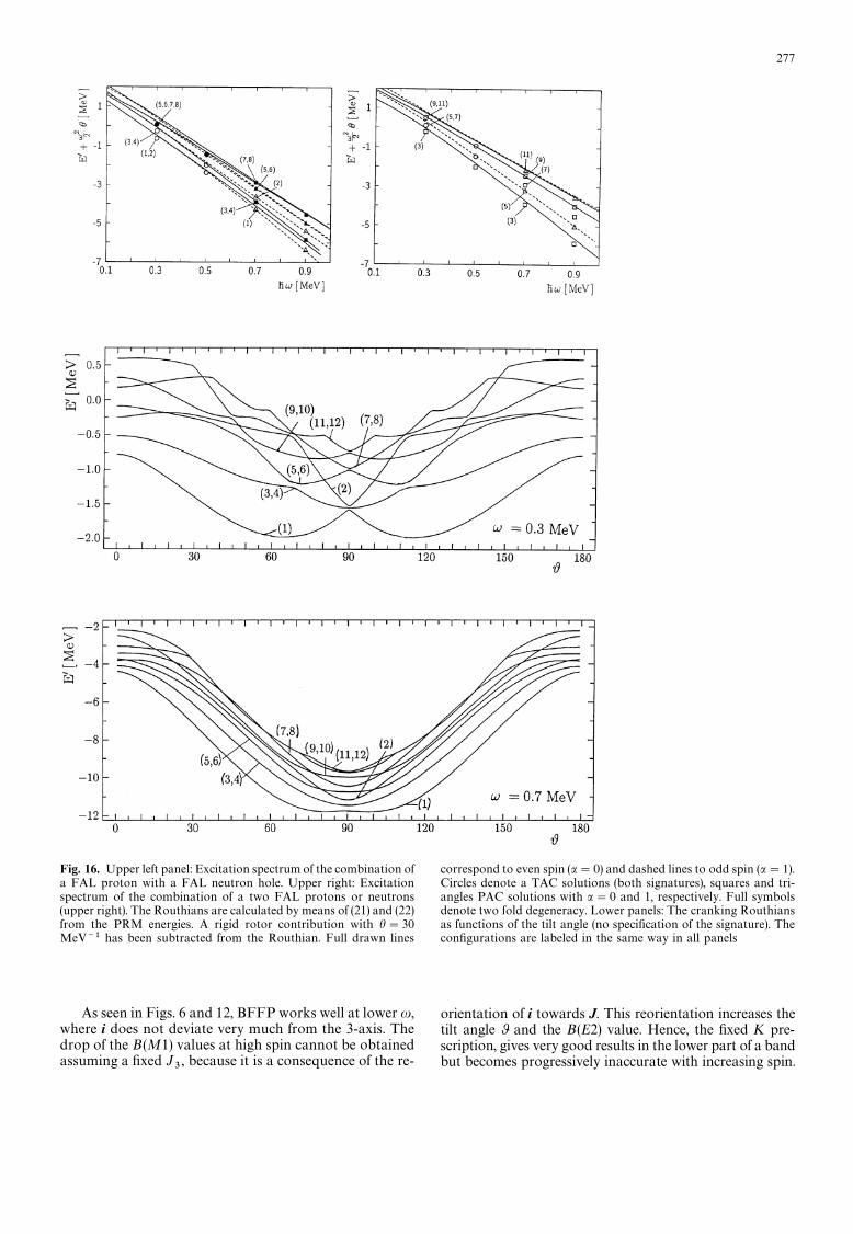
Fig. 16. Upper left panel: Excitation spectrum of the combination ofa FAL proton with a FAL neutron hole. Upper right: Excitationspectrum of the combination of a two FAL protons or neutrons(upper right). The Routhians are calculated by means of (21) and (22)from the PRM energies. A rigid rotor contribution with h"30MeV~1 has been subtracted from the Routhian. Full drawn lines
correspond to even spin (a"0) and dashed lines to odd spin (a"1).Circles denote a TAC solutions (both signatures), squares and tri-angles PAC solutions with a"0 and 1, respectively. Full symbolsdenote two fold degeneracy. Lower panels: The cranking Routhiansas functions of the tilt angle (no specification of the signature). Theconfigurations are labeled in the same way in all panels
As seen in Figs. 6 and 12, BFFP works well at lower u,where i does not deviate very much from the 3-axis. Thedrop of the B(M1) values at high spin cannot be obtainedassuming a fixed J
3, because it is a consequence of the re-
orientation of i towards J. This reorientation increases thetilt angle 0 and the B(E2) value. Hence, the fixed K pre-scription, gives very good results in the lower part of a bandbut becomes progressively inaccurate with increasing spin.
277
RMB that uses J3"JS j2
3T works well for the case of
one quasi particle (cf. [9 13]).8 However, as seen in Figs.6 and 12, it deviates considerably from the PRM in thecase of two quasi particles. Near the band head a onequasi particle state of good signature is given by
D$T+1
J2( DkT$D!kT), S$D j2
3D$T+k2, (34)
what amounts to J3+k. For the lowest two quasi particle
states
D$$T+12( Dk
pT$D!k
pT)( Dk
nT$D!k
nT) (35)
and one finds
J3"JS$$D j2
3D$$T+J1
2(k2
p#k2
n) (36)
instead of J3+k
p#k
n. Thus, for multi quasi particle
states RMB fails. As can be seen in Figs. 6 and 12, theversion FM suggested in this paper avoids this problem,because J
3is calculated as the sum of the individual
contributions i3p (n)
"JSp(n) D j23D p (n)T.
One may modify the PAC expression (25) for theB(M1) values in order to incorporate the tilted geometry,
B(M1)"3
8n[(gq!g
R)(J2S1 D j
$1q D2T#(sin0!1)i3q)
!cos0 ((gp!g
R) i1p#(g
n!g
R)i1n
)]2, (37)
i3q"S1 D j
3q D2T, cos0"i3q/J1
. (38)
For the case of one quasi particle, this expression essen-tially agrees with the modification of the DF formula,suggested by Donau [13] in order to describe signatureeffects.9 As demonstrated there and in Fig. 4, it describesrather well the B (M1) values in the whole spin range,including the signature staggering. However, this is notthe case for two quasi particles, as shown in Fig. 12.Though it somewhat improves the B (M1) values in thePAC limit it fails at low spin and it does not merge theTAC results any better than the uncorrected expression(25). Hence, it seems only to be possible to construct anB(M1) expression that describes both the tilted geometryand the signature staggering if the J
3component of the
angular momentum is generated by one quasi particle.This should be taken as a warning when analyzing data interms of the DF formula, using alignments estimated fromthe experimental spectra. Only for the cases when J
3comes from just one quasi particle, one may incorporatethe signature splitting by means of (37). If this is not thecase one must use the original DF expression (23). whichdoes not describe the signature dependence of the B(M1)values, but only averages over the two signatures.
8Comparing the PRM with PAC, [13] had to introduce a shift inangular momentum in order to match the results. This turns out tobe unnecessary in our comparison. The reason is that we keep therecoil term in our PRM in contrast to [13]9The term sin 0 i
3q in Donau’s expression corresponds to a some-what different 0 value
5 Conclusions
Comparing with the results of a Particle Rotor Modelcalculation, we find that the Tilted Axis Cranking ap-proach quantitatively accounts both for the energies andthe intra band transition rates of the lowest bands gener-ated by one or two quasi particles coupled to an axialrotor. It is expected that Tilted Axis Cranking works withcomparable accuracy for multi quasi particle bands,which are difficult to describe in the frame of the ParticleRotor Model.
Tilted Axis Cranking provides an accurate descriptionof the band head, except in cases, when substantial align-ment of quasi particle angular momentum occurs at verylow frequency.
The interpretation of the Cranking results suggested in[3], which associates minima at a tilt angle 0O90° withDI"1 bands and such at 90° with DI"2 bands of theappropriate signature, turned out to be correct. The inter-pretation has been refined by a set of rules that permits toconstruct the excited bands from the cranking config-urations. Applying these rules leads to a one to onecorrespondence with the low lying bands of the ParticleRotor Model calculations. No spurious configurations aregenerated.
The main draw back of the Tilted Axis Crankingtheory is the necessity to switch between two differentinterpretations. Such change of interpretation is alwaysnecessary when the mean field solution breaks spontan-eously a symmetry. In the considered case the C
2sym-
metry is broken and the signature quantum number lost.As a consequence, the Tilted Axis Cranking theory cannotdescribe the gradual onset of signature splitting, whichappears discontinuously when changing from the TAC tothe PAC interpretation. Sufficiently far from the discon-tinuity the energies and transition probabilities are quitewell reproduced by the semi classical expressions. Thetransition region may be bridged by interpolation ina qualitative way. Other quantities like mixing ratios,static magnetic moments and quadrupole moments, havealso been studied. Tilted Axis Cranking describes themwith comparable accuracy as the B (M1) and B(E2) values,discussed.
As in the standard cranking theory, the mixing ofbands with substantially different quasi particle angularmomentum cannot be described by Tilted Axis Cranking.
Previous schemes to account for finite angular mo-mentum along the symmetry axis that stay within theframe of rotation about the principal axes have beeninvestigated. Generally they agree less well with the Par-ticle Rotor Model than the Tilted Axis Cranking ap-proach. An exception is the case of one quasi particle,where they work well and provide even a description ofthe signature effects. However, for two quasi particles thisis generally no longer the case.
The particle rotor model was used in this study as an‘‘exact model’’ against which the semi classical Tilted AxisCranking was checked. The aim was to outline the limita-tions of Tilted Axis Cranking due to the violation ofangular momentum conservation and to test its accuracy.Tilted Axis Cranking is a microscopic theory that in manyrespects goes far beyond the Particle Rotor Model. For
278

example, one may easily study multi-quasi particle excita-tions, and the consequences of changes of the deformationor the pairing. Furthermore, it gives transparent classicalpictures of the angular momentum coupling.
The authors would like to thank F. Donau for numerous discussionsduring the completion of this work. J.M. would like to thank FZRfor the fellowship and the hospitality extended to him. He is alsopartly supported by the National Science Foundation in China.
References
1. Frisk, H., Bengtsson, R.: Phys. Lett. B196, 14 (1987)2. Frauendorf, S., Bengtsson, T.: Int. Symp. on Future Directions
in Nuclear Physics, Strasbourg 1991, AIP Con. Proc. 259, p. 223
3. Frauendorf, S.: Nucl. Phys. A557, 259c (1993)4. Frauendorf, S., Meng, J., Reif, J.: Proc. Conf. on Phys. from
Large c Ray Detectors, Berkeley 1994, p. 545. Brokstedt, A. et al.: Nucl. Phys. A578, 337 (1994)6. Baldsiefen, G. et al.: Nucl. Phys. A 574, 521 (1994)7. Szymanski, Z.: Fast Nuclear Rotation, p. 29 ff. Oxford: Claren-
don Press 19838. Bohr, A., Mottelson, B.: Nuclear Structure II, p. 1 ff. New York:
Benjamin 19759. Ring, P., Mang, H.J., Banerjee, B.: Nucl. Phys. A225, 141 (1974)
10. Bengtsson, R., Frauendorf, S.: Nucl. Phys. A327, 139 (1979)11. Fassler, A., Plozajczak, M.: Phys. Rev. C 16, 2032 (1977)12. Donau, F., Frauendorf, S.: Proc. Conf. on High Angular Mo-
mentum Properties of Nuclei, Oak Ridge 1982, Nucl. Sci. Res.Con. Ser. V. 4 Harwood NY, p. 143
13. Donau, F.: Nucl. Phys. A471, 469 (1987)14. Hamamoto, I., Sagawa, H.: Nucl. Phys. A327, 99 (1979)15. Frauendorf, S.: Phys. Scr. 24, 349 (1981)
.
279