Embed Size (px)
Citation preview
Interoperable testbenches using VMM TLM
Asif Jafri
Verilab Inc.
Austin, USA
www.verilab.com
Nasib Naser, PhD
Synopsys Inc.
Austin, USA
www.synopsys.com
ABSTRACT
SOC’s are getting larger all the time and so is the challenge to verify these designs in a short
period of time. This paper presents a transaction level-based methodology in the VMM to stan-
dardize development of various pieces of a verification environment and the communication be-
tween them. This methodology promotes reuse and helps integrate modules from various sources
to interact together seamlessly.
SNUG 2010 2 Interoperable Testbenches using VMM TLM
Table of Contents
1. Introduction ........................................................................................................................... 4 INTRODUCTION TO OSCI TLM ..................................................................................................... 4 INTRODUCTION TO VMM ............................................................................................................. 5
2. Issues ..................................................................................................................................... 5
3. Building blocks ..................................................................................................................... 5
TRANSPORT INTERFACES .............................................................................................................. 5 Blocking Interfaces ................................................................................................................... 6 Non-Blocking Interfaces ........................................................................................................... 6
PORTS AND EXPORTS .................................................................................................................... 8 ANALYSIS PORTS .......................................................................................................................... 8
SOCKETS ....................................................................................................................................... 9
BINDING ..................................................................................................................................... 10
GENERIC PAYLOADS ................................................................................................................... 10 CONNECTING CHANNELS TO TLM .............................................................................................. 10
CONNECTING ATOMIC GENERATORS AND SCENARIO GENERATORS TO TLM USING CHANNELS 11
4. Putting it all together ........................................................................................................... 12
5. Integrating a SystemC reference model to your VMM test bench ..................................... 13 LIMITATIONS OF THE SYSTEMVERILOG DIRECT PROGRAMMING INTERFACE (DPI) ..................... 13 TRANSACTION LEVEL INTERFACE FOR INTEGRATING SYSTEMC MODELS ................................... 13
6. Results ................................................................................................................................. 18
7. Conclusions ......................................................................................................................... 18
8. References ........................................................................................................................... 18
SNUG 2010 3 Interoperable Testbenches using VMM TLM
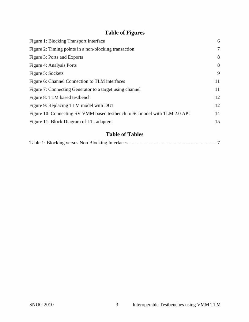
Table of Figures
Figure 1: Blocking Transport Interface 6
Figure 2: Timing points in a non-blocking transaction 7
Figure 3: Ports and Exports 8
Figure 4: Analysis Ports 8
Figure 5: Sockets 9
Figure 6: Channel Connection to TLM interfaces 11
Figure 7: Connecting Generator to a target using channel 11
Figure 8: TLM based testbench 12
Figure 9: Replacing TLM model with DUT 12
Figure 10: Connecting SV VMM based testbench to SC model with TLM 2.0 API 14
Figure 11: Block Diagram of LTI adapters 15
Table of Tables
Table 1: Blocking versus Non Blocking Interfaces ........................................................................ 7
SNUG 2010 4 Interoperable Testbenches using VMM TLM
1. Introduction
Verifying an SOC is a very hard problem to solve when components of the design are obtained
from various sources and are delivered during different phases of the project. If these compo-
nents use a common communications platform it is easier to piece them together. Following a
scheme such as Transaction Level Modeling (TLM) will not only facilitate quick integration of
your verification environment, but is also useful in integrating SystemC reference models into
the design when RTL is not available.
Modeling and communication presents SOC development teams with many challenges like
verifying their designs in a mixed-language and mixed-abstraction level environment while
meeting compressed schedules. Two languages in particular are increasingly popular for SOC
development: IEEE Std 1800 SystemVerilog with its advanced verification, modeling and
hardware design capabilities; and IEEE Std 1666 SystemC, with powerful modeling features and
tight links to the C/C++ programming languages. The challenge faced by many SOC teams is
how to use these languages together for mixed-language, mixed-abstraction level verification.
Mixed abstractions come from the fact that designers often develop models at the transaction
level to capture the correct architecture and analyze the system performance fairly early in the
design cycle. Various components of an SOC developed with high level languages such as C,
C++, SystemC, and SystemVerilog are increasingly in demand and for obvious reasons. They are
faster to write and faster to simulate.
We will start off by introducing the OSCI-TLM standard and VMM. Some issues that need to
be addressed will be discussed. Then we will describe in detail the basic building blocks of the
VMM TLM based design. Next these standard interfaces will be used to build a verification en-
vironment for an Ethernet controller. Examples will demonstrate how VMM TLM enhances the
reusability of testbench components. We conclude with an example demonstrating how to con-
nect a SystemC based model of the controller to your verification environment.
Introduction to OSCI TLM
Transaction Level Modelling in a language agnostic term is a modelling scheme and coding
style that enables seamless and faster system composition. This modelling paradigm yields to a
shorter system validation time and faster simulation. Coincidently these features are essential for
finding functional bugs early in the design cycle and improves interoperability capabilities.
The Open SystemC Initiative thru the TLM working group established a TLM standard that
has been adopted by many architects, designers and IP providers. The standard supports software
development, software performance testing, architectural analysis, and hardware verification.
These use models are not limited to a specific coding style. The TLM standard calls for Loosely-
timed (models that contain a limited amount of timing information) and Approximately-timed
coding styles (models that are more cycle accurate). Models could be developed using other cod-
ing styles such as cycle accurate and cycle approximate. Many processor models and Instruction
Set Simulators are developed in such a style. To ensure interoperability one should adhere to the
recommended code styles. Furthermore, mechanisms have been standardized to compliment the
SNUG 2010 5 Interoperable Testbenches using VMM TLM
aforementioned use models and coding styles. These are Blocking and Non-Blocking interfaces,
Direct Memory Interface, Global Quantum, Sockets, and Phases.
This paper will not elaborate on the OSCI-TLM features but rather how the TLM standard is
being adopted by VMM to enhance testbench interoperability. Details of this standard can be
found in the OSCI TLM-2.0 Language Reference Manual which is downloadable from
www.systemc.org.
Introduction to VMM
SystemVerilog allows for the creation of powerful, reusable layered testbench architectures.
A layered approach is where the testbench is divided into various layers, like the the test layer,
the generation layer, the driver layer etc. The The VMM methodology is a standard for creating
SystemVerilog verification environments which provides such a layered architecture. With a
layered approach, transaction-level reference models written in SystemVeilog or SystemC can be
easily integrated at the appropriate level to provide self-checking functions.
2. Issues
Very often at the beginning of a project we have to make tough decisions as to how a
testbench needs to be portitioned and layed out. Verification environments may include drivers,
generators, monitors, scoreboards, scenario generators, and/or atomic generators. All of these
components usually communicate with each other usually through channels.TLM is an industry
standard used for communication. So why not start off with all these components communicating
over TLM interfaces. TLM introduces the use of a common transaction type called generic payl-
oad which can be used to pass transactions from one verification layer to another. One can easily
adapt a protocol specific transaction into the generic payload. This once again helps when com-
municating between various vendor IP’s or across languages that support TLM.
If our current testbench is talking to an Ethernet controller over a PCIE interface, and later on
the project requires us to use an AMBA interface also, the complete interface will need to be
changed. However, using TLM compliant code will save us time as the same function call can
either drive the PCIE driver IP or the AMBA driver IP.
Often the RTL is not available in time, but more and more companies are using SystemC func-
tional models which can be used to start off the verification process. This will also help us
achieve faster simulation speeds.
3. Building blocks
OSCI TLM is comprised of several building blocks. In any verification environment we have
transactions starting from one node which could be a generator, driver etc. This node will be re-
ferred to as an Initiator and a node responding to transaction will be referred to as a target.
Transport Interfaces
The transport interface is a collection of methods which defines a connection between an initiator
and a target. They can be blocking or non-blocking in nature.
SNUG 2010 6 Interoperable Testbenches using VMM TLM
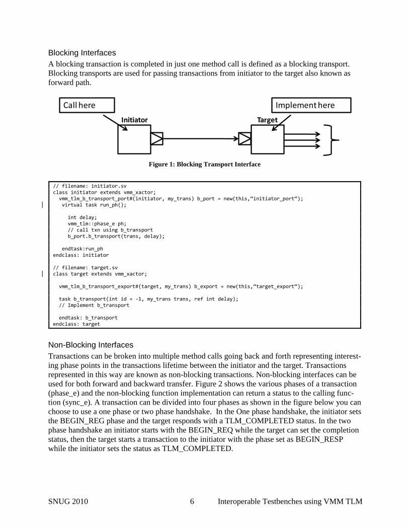
Blocking Interfaces
A blocking transaction is completed in just one method call is defined as a blocking transport.
Blocking transports are used for passing transactions from initiator to the target also known as
forward path.
Initiator Target
Call here Implement here
Figure 1: Blocking Transport Interface
// filename: initiator.sv class initiator extends vmm_xactor; vmm_tlm_b_transport_port#(initiator, my_trans) b_port = new(this,“initiator_port“); virtual task run_ph(); int delay; vmm_tlm::phase_e ph; // call txn using b_transport b_port.b_transport(trans, delay); endtask:run_ph endclass: initiator // filename: target.sv class target extends vmm_xactor; vmm_tlm_b_transport_export#(target, my_trans) b_export = new(this,“target_export“); task b_transport(int id = -1, my_trans trans, ref int delay); // Implement b_transport endtask: b_transport endclass: target
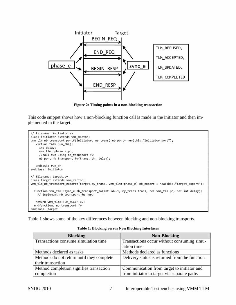
Non-Blocking Interfaces
Transactions can be broken into multiple method calls going back and forth representing interest-
ing phase points in the transactions lifetime between the initiator and the target. Transactions
represented in this way are known as non-blocking transactions. Non-blocking interfaces can be
used for both forward and backward transfer. Figure 2 shows the various phases of a transaction
(phase_e) and the non-blocking function implementation can return a status to the calling func-
tion (sync_e). A transaction can be divided into four phases as shown in the figure below you can
choose to use a one phase or two phase handshake. In the One phase handshake, the initiator sets
the BEGIN_REG phase and the target responds with a TLM_COMPLETED status. In the two
phase handshake an initiator starts with the BEGIN_REQ while the target can set the completion
status, then the target starts a transaction to the initiator with the phase set as BEGIN_RESP
while the initiator sets the status as TLM_COMPLETED.
SNUG 2010 7 Interoperable Testbenches using VMM TLM
phase_e
BEGIN_REQ
END_REQ
BEGIN_RESP
END_RESP
sync_e
Initiator Target
TLM_REFUSED,
TLM_ACCEPTED,
TLM_UPDATED,
TLM_COMPLETED
Figure 2: Timing points in a non-blocking transaction
This code snippet shows how a non-blocking function call is made in the initiator and then im-
plemented in the target.
// filename: initiator.sv class initiator extends vmm_xactor; vmm_tlm_nb_transport_port#(initiator, my_trans) nb_port= new(this,“initiator_port“); virtual task run_ph(); int delay; vmm_tlm::phase_e ph; //call txn using nb_transport fw nb_port.nb_transport_fw(trans, ph, delay); endtask: run_ph endclass: initiator // filename: target.sv class target extends vmm_xactor; vmm_tlm_nb_transport_export#(target,my_trans, vmm_tlm::phase_e) nb_export = new(this,”target_export”); function vmm_tlm::sync_e nb_transport_fw(int id=-1, my_trans trans, ref vmm_tlm ph, ref int delay); // Implement nb_transport_fw here return vmm_tlm::TLM_ACCEPTED; endfunction: nb_transport_fw endclass: target
Table 1 shows some of the key differences between blocking and non-blocking transports.
Table 1: Blocking versus Non Blocking Interfaces
Blocking Non-Blocking
Transactions consume simulation time Transactions occur without consuming simu-
lation time
Methods declared as tasks Methods declared as functions
Methods do not return until they complete
their transaction
Delivery status is returned from the function
Method completion signifies transaction
completion
Communication from target to initiator and
from initiator to target via separate paths
SNUG 2010 8 Interoperable Testbenches using VMM TLM
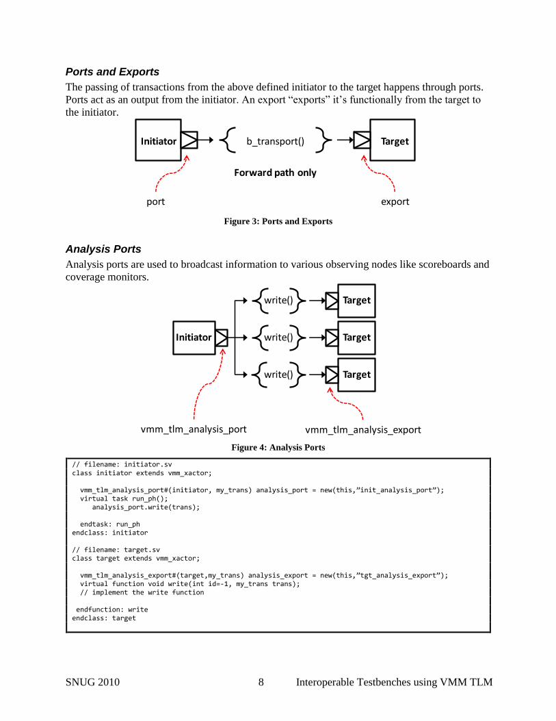
Ports and Exports
The passing of transactions from the above defined initiator to the target happens through ports.
Ports act as an output from the initiator. An export “exports” it’s functionally from the target to
the initiator.
Forward path only
Initiator b_transport() Target
port export
Figure 3: Ports and Exports
Analysis Ports
Analysis ports are used to broadcast information to various observing nodes like scoreboards and
coverage monitors.
write() Target
write()
write()
vmm_tlm_analysis_port vmm_tlm_analysis_export
Target
Target
Initiator
Figure 4: Analysis Ports
// filename: initiator.sv class initiator extends vmm_xactor; vmm_tlm_analysis_port#(initiator, my_trans) analysis_port = new(this,”init_analysis_port”); virtual task run_ph(); analysis_port.write(trans); endtask: run_ph endclass: initiator // filename: target.sv class target extends vmm_xactor; vmm_tlm_analysis_export#(target,my_trans) analysis_export = new(this,”tgt_analysis_export”); virtual function void write(int id=-1, my_trans trans); // implement the write function endfunction: write endclass: target
SNUG 2010 9 Interoperable Testbenches using VMM TLM
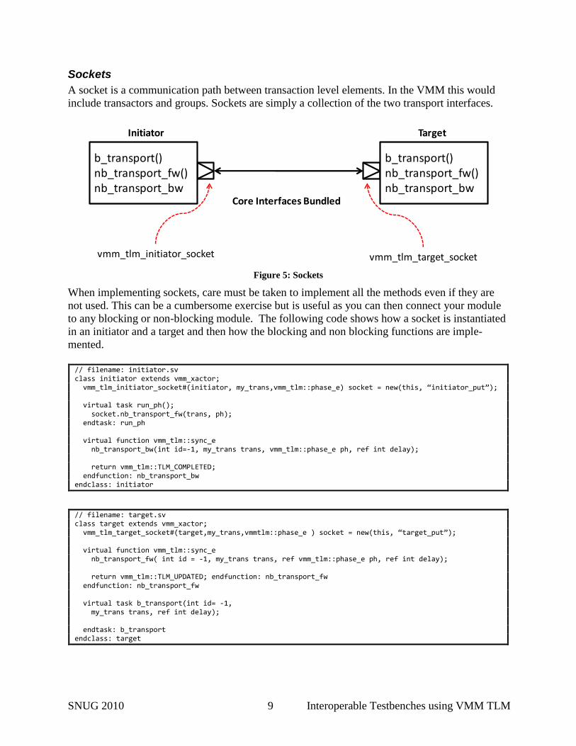
Sockets
A socket is a communication path between transaction level elements. In the VMM this would
include transactors and groups. Sockets are simply a collection of the two transport interfaces.
vmm_tlm_target_socket
b_transport()nb_transport_fw()nb_transport_bw()
Initiator Target
vmm_tlm_initiator_socket
Core Interfaces Bundled
b_transport()nb_transport_fw()nb_transport_bw()
Figure 5: Sockets
When implementing sockets, care must be taken to implement all the methods even if they are
not used. This can be a cumbersome exercise but is useful as you can then connect your module
to any blocking or non-blocking module. The following code shows how a socket is instantiated
in an initiator and a target and then how the blocking and non blocking functions are imple-
mented.
// filename: initiator.sv class initiator extends vmm_xactor; vmm_tlm_initiator_socket#(initiator, my_trans,vmm_tlm::phase_e) socket = new(this, “initiator_put”); virtual task run_ph(); socket.nb_transport_fw(trans, ph); endtask: run_ph virtual function vmm_tlm::sync_e nb_transport_bw(int id=-1, my_trans trans, vmm_tlm::phase_e ph, ref int delay); return vmm_tlm::TLM_COMPLETED; endfunction: nb_transport_bw endclass: initiator
// filename: target.sv class target extends vmm_xactor; vmm_tlm_target_socket#(target,my_trans,vmmtlm::phase_e ) socket = new(this, “target_put”); virtual function vmm_tlm::sync_e nb_transport_fw( int id = -1, my_trans trans, ref vmm_tlm::phase_e ph, ref int delay); return vmm_tlm::TLM_UPDATED; endfunction: nb_transport_fw endfunction: nb_transport_fw virtual task b_transport(int id= -1, my_trans trans, ref int delay); endtask: b_transport endclass: target
SNUG 2010 10 Interoperable Testbenches using VMM TLM
Binding
Now that we have an initiator and a target with the transport interfaces defining the communi-
cation between them and have instantiated sockets or ports/exports in them, it is time to create a
physical link between them. This can be achieved by binding the ports to exports or binding the
initiator_socket to the target_socket.
// filename: initiator.sv class initiator extends vmm_xactor; vmm_tlm_b_transport_port#(initiator, my_trans) b_port = new(this,"initiator_port"); endclass: initiator // filename: target.sv class target extends vmm_xactor; vmm_tlm_b_transport_export#(target, my_trans) b_export = new(this,"target_export"); endclass: target // filename: group_env.sv class my_group extends vmm_group; //instantiate the initiator and target to be connected initiator initiator0; target target0; virtual function void connect_ph(); initiator0.b_port.tlm_bind(target0.b_export); endfunction: connect_ph endclass: my_group
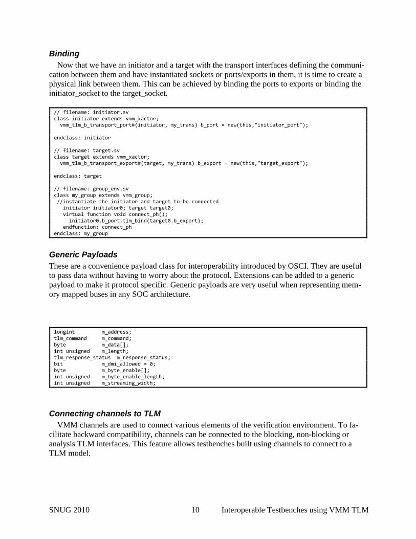
Generic Payloads
These are a convenience payload class for interoperability introduced by OSCI. They are useful
to pass data without having to worry about the protocol. Extensions can be added to a generic
payload to make it protocol specific. Generic payloads are very useful when representing mem-
ory mapped buses in any SOC architecture.
longint m_address; tlm_command m_command; byte m_data[]; int unsigned m_length; tlm_response_status m_response_status; bit m_dmi_allowed = 0; byte m_byte_enable[]; int unsigned m_byte_enable_length; int unsigned m_streaming_width;
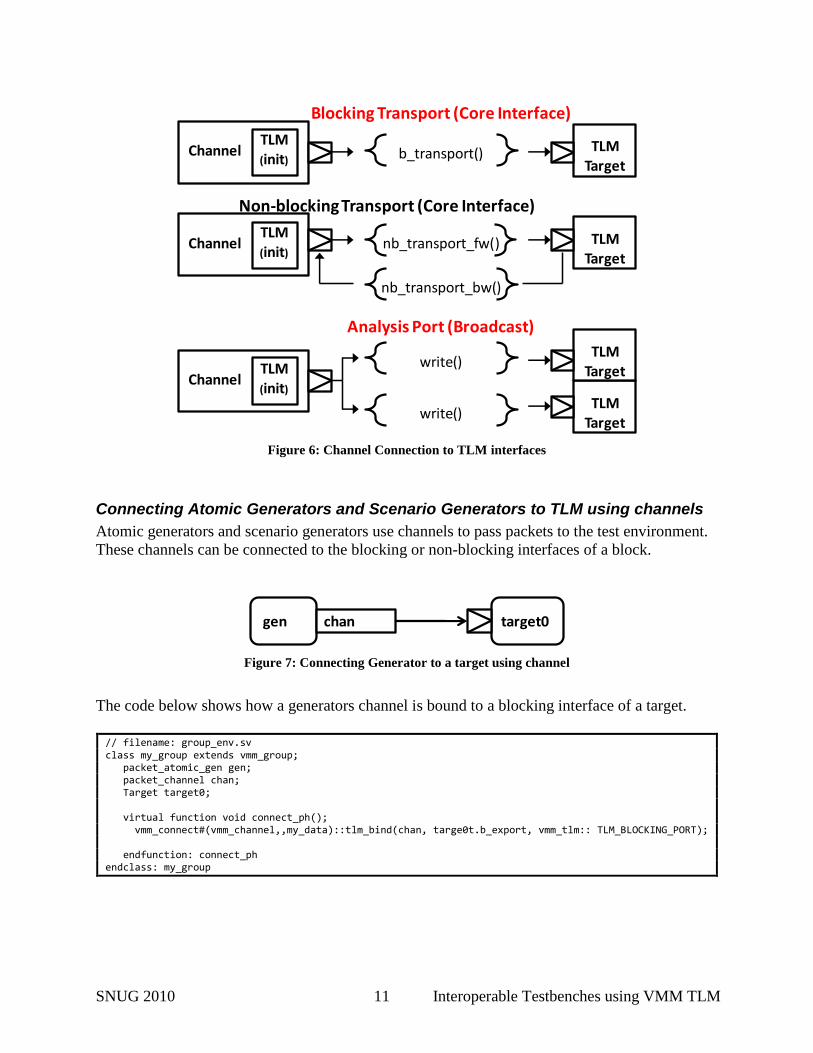
Connecting channels to TLM
VMM channels are used to connect various elements of the verification environment. To fa-
cilitate backward compatibility, channels can be connected to the blocking, non-blocking or
analysis TLM interfaces. This feature allows testbenches built using channels to connect to a
TLM model.
SNUG 2010 11 Interoperable Testbenches using VMM TLM
Non-blocking Transport (Core Interface)
nb_transport_fw()
nb_transport_bw()
TLMTarget
TargetTLM(init)
Channel
b_transport()
Blocking Transport (Core Interface)
TLMTarget
TargetTLM(init)
Channel
write()
write()Target
Analysis Port (Broadcast)
TLMTarget
TargetTLM(init)
Channel
TLMTarget
TLMTarget
Figure 6: Channel Connection to TLM interfaces
Connecting Atomic Generators and Scenario Generators to TLM using channels
Atomic generators and scenario generators use channels to pass packets to the test environment.
These channels can be connected to the blocking or non-blocking interfaces of a block.
target0gen chan
Figure 7: Connecting Generator to a target using channel
The code below shows how a generators channel is bound to a blocking interface of a target.
// filename: group_env.sv class my_group extends vmm_group; packet_atomic_gen gen; packet_channel chan; Target target0; virtual function void connect_ph(); vmm_connect#(vmm_channel,,my_data)::tlm_bind(chan, targe0t.b_export, vmm_tlm:: TLM_BLOCKING_PORT); endfunction: connect_ph endclass: my_group
SNUG 2010 12 Interoperable Testbenches using VMM TLM
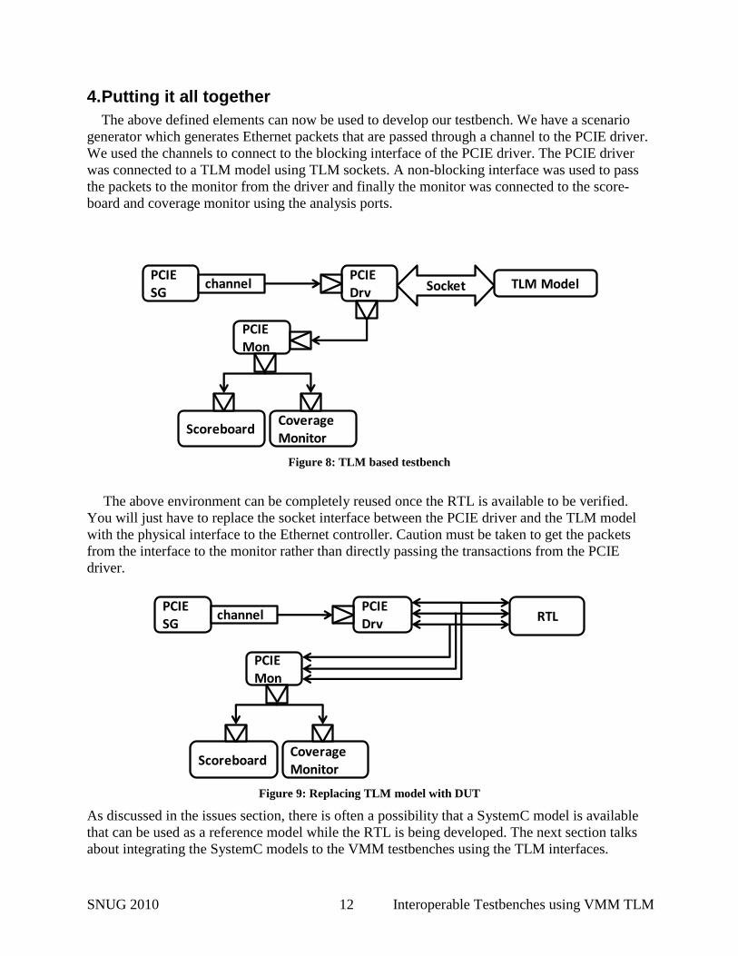
4. Putting it all together
The above defined elements can now be used to develop our testbench. We have a scenario
generator which generates Ethernet packets that are passed through a channel to the PCIE driver.
We used the channels to connect to the blocking interface of the PCIE driver. The PCIE driver
was connected to a TLM model using TLM sockets. A non-blocking interface was used to pass
the packets to the monitor from the driver and finally the monitor was connected to the score-
board and coverage monitor using the analysis ports.
SocketPCIEDrv
PCIESG
TLM Model
ScoreboardCoverageMonitor
PCIEMon
channel
Figure 8: TLM based testbench
The above environment can be completely reused once the RTL is available to be verified.
You will just have to replace the socket interface between the PCIE driver and the TLM model
with the physical interface to the Ethernet controller. Caution must be taken to get the packets
from the interface to the monitor rather than directly passing the transactions from the PCIE
driver.
PCIEDrv
PCIESG
RTL
ScoreboardCoverageMonitor
PCIEMon
channel
Figure 9: Replacing TLM model with DUT
As discussed in the issues section, there is often a possibility that a SystemC model is available
that can be used as a reference model while the RTL is being developed. The next section talks
about integrating the SystemC models to the VMM testbenches using the TLM interfaces.
SNUG 2010 13 Interoperable Testbenches using VMM TLM
5. Integrating a SystemC reference model with your VMM testbench
Limitations of the SystemVerilog Direct Programming Interface (DPI) Integrating a reference model written in SystemC to a verification environment written in
SystemVerilog requires some sort of defined, programmatic interface. In the past, this was
achieved with the Verilog PLI, sockets or pipes. These approaches suffered from performance
and other bottlenecks. The SystemVerilog language standard defines a Direct Programming
Interface (DPI) which alleviates many of these bottlenecks.
DPI is part of the SystemVerilog standard. It’s an efficient interface between SystemVerilog
and a foreign programming language. By the use of the “import” and “export” constructs DPI
lets SystemVerilog call a C function just like any other native SystemVerilog function and task.
Its benefit is that it significantly reduces the complexity of interfacing to C models.
In a mixed SystemVerilog/ SystemC environment, the DPI is recommended for non-time-
consuming functions that don’t require blocking calls. In simple terms, DPI is ideal for passing
SystemVerilog data between the two domains through function arguments and results. There is
no intrinsic overhead in this interface. DPI imported and exported functions are assumed to
complete their execution instantly at zero simulation time.
The SystemVerilog DPI was targeted primarily for calling C functions, not SystemC. This
introduces several challenges when trying to integrate SystemC class methods via DPI. First,
DPI cannot be used to traverse hierarchy where handles to instances or objects are not possible.
Second, the DPI cannot call blocking (i.e., time consuming) SystemC methods, for example with
a wait(10, SC_NS) statement. Third, other SystemC processes must continue while one is
suspended in blocking export-DPI task. DPI also provides no means of synchronization other
than by data exchange and explicit transfer of control. These limitations make it difficult if not
impossible to interface a SystemC cycle accurate, time consuming model in a SystemVerilog
environment.
Transaction Level Interface for integrating SystemC models
Synopsys’ VCS functional verification solution addresses the challenge of integrating
SystemC reference models with its SystemC-SystemVerilog Transaction-Level Interface (TLI).
Using TLI SystemC interface methods can be invoked in SystemVerilog and vice versa. This
provides an automated, transaction-level link between both languages.
Both SystemC and SystemVerilog have concepts of interfaces. An interface separates the
communication from its implementation. SystemC interfaces are implemented using C++ classes
(methods associated with the data member of the class) and SystemVerilog languages itself
consists of interface construct defining set of signals and associated methods. Semantics of
interfaces in both the languages are identical.
The automated generation of the communication code alleviates the difficulties in
implementing a synchronized communication mechanism to fully integrate transaction-level,
cycle-accurate SystemC models into a SystemVerilog environment using DPI.
SystemVerilog allows for the creation of powerful, reusable layered testbench architectures.
The VMM methodology, a de facto standard for creating SystemVerilog verification
environments, provides such a layered architecture. With a layered approach, transaction-level
reference models can be easily integrated at the appropriate level to provide self-checking
functions.
SNUG 2010 14 Interoperable Testbenches using VMM TLM
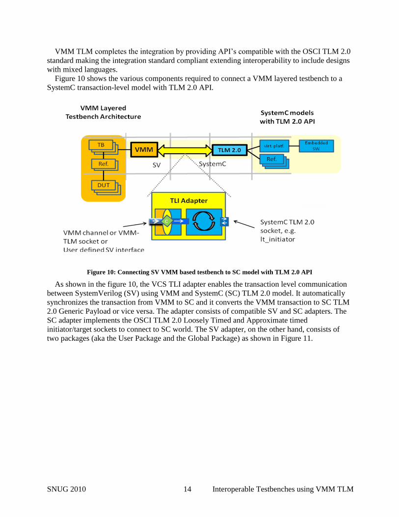
VMM TLM completes the integration by providing API’s compatible with the OSCI TLM 2.0
standard making the integration standard compliant extending interoperability to include designs
with mixed languages.
Figure 10 shows the various components required to connect a VMM layered testbench to a
SystemC transaction-level model with TLM 2.0 API.
Figure 10: Connecting SV VMM based testbench to SC model with TLM 2.0 API
As shown in the figure 10, the VCS TLI adapter enables the transaction level communication
between SystemVerilog (SV) using VMM and SystemC (SC) TLM 2.0 model. It automatically
synchronizes the transaction from VMM to SC and it converts the VMM transaction to SC TLM
2.0 Generic Payload or vice versa. The adapter consists of compatible SV and SC adapters. The
SC adapter implements the OSCI TLM 2.0 Loosely Timed and Approximate timed
initiator/target sockets to connect to SC world. The SV adapter, on the other hand, consists of
two packages (aka the User Package and the Global Package) as shown in Figure 11.
SNUG 2010 15 Interoperable Testbenches using VMM TLM
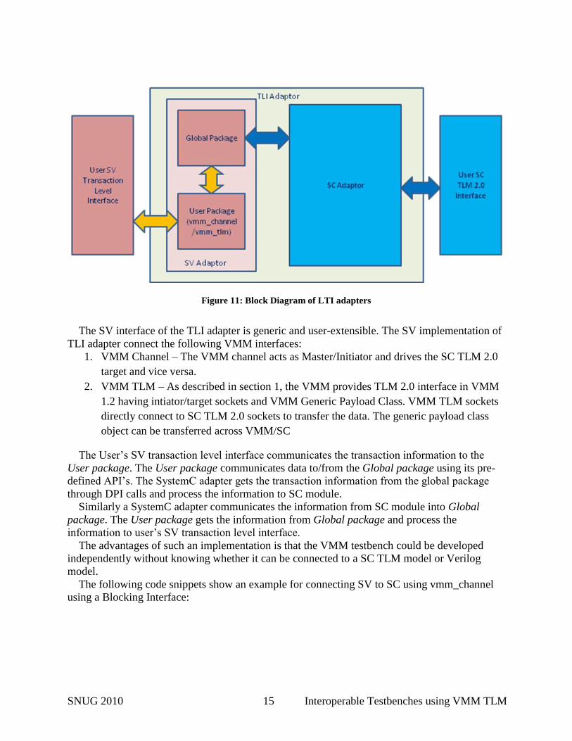
Figure 11: Block Diagram of LTI adapters
The SV interface of the TLI adapter is generic and user-extensible. The SV implementation of
TLI adapter connect the following VMM interfaces:
1. VMM Channel – The VMM channel acts as Master/Initiator and drives the SC TLM 2.0
target and vice versa.
2. VMM TLM – As described in section 1, the VMM provides TLM 2.0 interface in VMM
1.2 having intiator/target sockets and VMM Generic Payload Class. VMM TLM sockets
directly connect to SC TLM 2.0 sockets to transfer the data. The generic payload class
object can be transferred across VMM/SC
The User’s SV transaction level interface communicates the transaction information to the
User package. The User package communicates data to/from the Global package using its pre-
defined API’s. The SystemC adapter gets the transaction information from the global package
through DPI calls and process the information to SC module.
Similarly a SystemC adapter communicates the information from SC module into Global
package. The User package gets the information from Global package and process the
information to user’s SV transaction level interface.
The advantages of such an implementation is that the VMM testbench could be developed
independently without knowing whether it can be connected to a SC TLM model or Verilog
model.
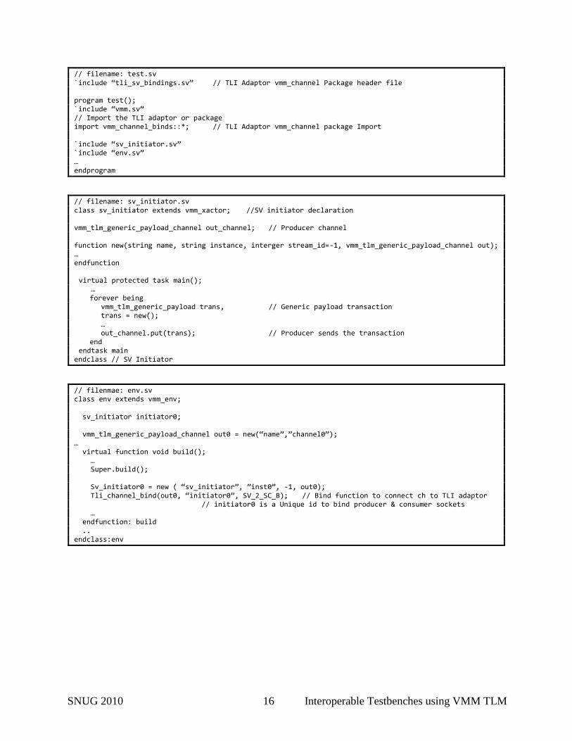
The following code snippets show an example for connecting SV to SC using vmm_channel
using a Blocking Interface:
SNUG 2010 16 Interoperable Testbenches using VMM TLM
// filename: test.sv `include “tli_sv_bindings.sv” // TLI Adaptor vmm_channel Package header file program test(); `include “vmm.sv” // Import the TLI adaptor or package import vmm_channel_binds::*; // TLI Adaptor vmm_channel package Import `include “sv_initiator.sv” `include “env.sv” … endprogram
// filename: sv_initiator.sv class sv_initiator extends vmm_xactor; //SV initiator declaration vmm_tlm_generic_payload_channel out_channel; // Producer channel function new(string name, string instance, interger stream_id=-1, vmm_tlm_generic_payload_channel out); … endfunction virtual protected task main();
… forever being vmm_tlm_generic_payload trans, // Generic payload transaction trans = new(); … out_channel.put(trans); // Producer sends the transaction end endtask main endclass // SV Initiator
// filenmae: env.sv class env extends vmm_env; sv_initiator initiator0; vmm_tlm_generic_payload_channel out0 = new(“name”,”channel0”); … virtual function void build(); … Super.build(); Sv_initiator0 = new ( “sv_initiator”, ”inst0”, -1, out0); Tli_channel_bind(out0, “initiator0”, SV_2_SC_B); // Bind function to connect ch to TLI adaptor // initiator0 is a Unique id to bind producer & consumer sockets … endfunction: build .. endclass:env
SNUG 2010 17 Interoperable Testbenches using VMM TLM
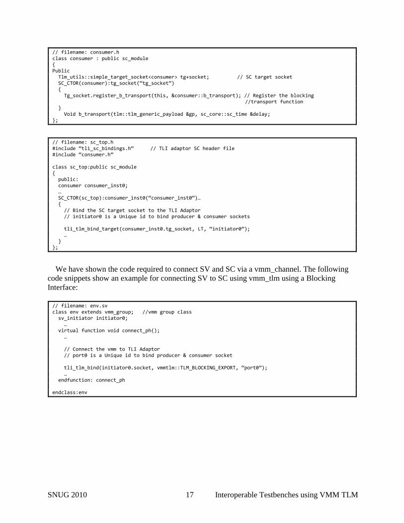
// filename: consumer.h class consumer : public sc_module { Public Tlm_utils::simple_target_socket<consumer> tg+socket; // SC target socket SC_CTOR(consumer):tg_socket(“tg_socket”) { Tg_socket.register_b_transport(this, &consumer::b_transport); // Register the blocking //transport function
} Void b_transport(tlm::tlm_generic_payload &gp, sc_core::sc_time &delay; };
// filename: sc_top.h #include “tli_sc_bindings.h” // TLI adaptor SC header file #include “consumer.h” class sc_top:public sc_module { public: consumer consumer_inst0; … SC_CTOR(sc_top):consumer_inst0(“consumer_inst0”)… { // Bind the SC target socket to the TLI Adaptor // initiator0 is a Unique id to bind producer & consumer sockets tli_tlm_bind_target(consumer_inst0.tg_socket, LT, “initiator0”); … } };
We have shown the code required to connect SV and SC via a vmm_channel. The following
code snippets show an example for connecting SV to SC using vmm_tlm using a Blocking
Interface:
// filename: env.sv class env extends vmm_group; //vmm group class sv_initiator initiator0; … virtual function void connect_ph(); … // Connect the vmm to TLI Adaptor // port0 is a Unique id to bind producer & consumer socket tli_tlm_bind(initiator0.socket, vmmtlm::TLM_BLOCKING_EXPORT, “port0”); … endfunction: connect_ph endclass:env
SNUG 2010 18 Interoperable Testbenches using VMM TLM
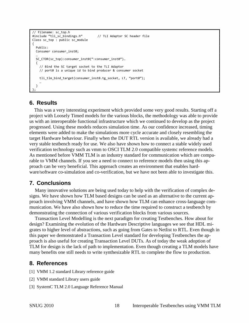
// filename: sc_top.h #include “tli_sc_bindings.h” // TLI Adaptor SC header file Class sc_top : public sc_module { Public: Consumer consumer_inst0; … SC_CTOR(sc_top):consumer_inst0(“:consumer_inst0”)… { // Bind the SC target socket to the TLI Adaptor // port0 is a unique id to bind producer & consumer socket tli_tlm_bind_target(consumer_inst0.tg_socket, LT, “port0”); … } };
6. Results
This was a very interesting experiment which provided some very good results. Starting off a
project with Loosely Timed models for the various blocks, the methodology was able to provide
us with an interoperable functional infrastructure which we continued to develop as the project
progressed. Using these models reduces simulation time. As our confidence increased, timing
elements were added to make the simulations more cycle accurate and closely resembling the
target Hardware behaviour. Finally when the DUT RTL version is available, we already had a
very stable testbench ready for use. We also have shown how to connect a stable widely used
verification technology such as vmm to OSCI TLM 2.0 compatible systemc reference models.
As mentioned before VMM TLM is an industry standard for communication which are compa-
rable to VMM channels. If you see a need to connect to reference models then using this ap-
proach can be very beneficial. This approach creates an environment that enables hard-
ware/software co-simulation and co-verification, but we have not been able to investigate this.
7. Conclusions
Many innovative solutions are being used today to help with the verification of complex de-
signs. We have shown how TLM based designs can be used as an alternative to the current ap-
proach involving VMM channels, and have shown how TLM can enhance cross-language com-
munication. We have also shown how to reduce the time required to construct a testbench by
demonstrating the connection of various verification blocks from various sources.
Transaction Level Modelling is the next paradigm for creating Testbenches. How about for
design? Examining the evolution of the Hardware Descriptive languages we see that HDL mi-
grates to higher level of abstractions, such as going from Gates to Netlist to RTL. Even though in
this paper we demonstrated a Transaction Level standard for developing Testbenches the ap-
proach is also useful for creating Transaction Level DUTs. As of today the weak adoption of
TLM for design is the lack of path to implementation. Even though creating a TLM models have
many benefits one still needs to write synthesizable RTL to complete the flow to production.
8. References
[1] VMM 1.2 standard Library reference guide
[2] VMM standard Library users guide
[3] SystemC TLM 2.0 Language Reference Manual