Embed Size (px)
Citation preview
Interoperability constraints and requirements formal modelling and checking framework
Vincent Chapurlat, Matthieu Roque
LGI2P - Laboratoire de Génie Informatique et d'Ingénierie de Production site EERIE de l’Ecole des Mines d’Alès, Parc Scientifique Georges Besse, F30035 Nîmes
cedex 5, France, {Vincent.Chapurlat, Matthieu.Roque}@ema.fr
Abstract: This paper aims to present and formalize the foundations of a modeling and checking framework for system requirements management. It is illustrated by the study of interoperability requirements having to be respected all along collaborative (private or public) processes.
Keywords: System requirement, modeling, verification, interoperability requirement
1. Introduction
For a long time, System theory has proposed paradigms and concepts (complexity vs. complication, system, system of systems, abstraction, multi views representation, interaction, processor, etc.) [1] in order to support and to help an actor involved in a process (engineering, decision, control) focusing on complex system. These paradigms allow: − to acquire and to formalize knowledge about this system and, − to acquire knowledge allowing to manage the process itself and, − to define and to argue what are the most relevant actions having to be done
regarding first, the objectives the studied system must reach in terms of performance, integrity and stability (safety, security, etc.) and second, the process environment, resources and context.
Various technical, industrial and scientific domains such as system engineering [2] or enterprise modeling [3, 4] for example, have declined and specialized these concepts and paradigms in order to take into account their specificities. Modeling frameworks, methods, languages and tools have been defined and developed. However, a question appears to have been treated unequally, or even completely forgotten by some domains because of its apparent disinterest or poor understanding of the actors. This question is: how the requirements of the studied system are really and efficiently defined, handled and verified all along the process and for doing what? This paper aims to present the foundations of a system requirements modeling and verification framework. This framework is applied here to describe and formalize
interoperability requirements when the considered system is a collaborative process in which various companies aim to be involved and work together. The illustrative example presented has been developed with the support of CARNOT-Mines Institute during the CARIONER project1 [5].
2. Problematic
All along an engineering process, the resulting product or service (the target system) but also the process itself (the management system) must respect several needs. A need can come logically from the customer of the target system or from the stakeholders having to interact with the target system during its life-cycle or during the engineering process itself (management rules…). It can be formalized by the use of languages such as SysML but remains usually described informally by actors with possible ambiguities in meaning of words, omissions or repetitions. Thus, to prove that the target system or the process satisfy a need become then difficult. The proposed framework aims to help actors (customers, stakeholders, engineers, managers) involved in the process first to formalize a need i.e. to list requirements, second to check these requirements on the different models. This work takes into account next hypothesis: − As proposed in Model Based System Engineering paradigm, and more generally
Model Driven Engineering [6], engineering process is led by the use and implementation of models. This induces first to define a requirement model able to formalize needs. Second, it is necessary to enrich existing modeling frameworks, languages, methods and tools considering this requirement model.
− Checking a requirement may use several techniques more or less formal [7, 8]: expertise of the model by a human expert, test on a prototype followed by an expertise, simulation e.g. for evaluating the system performances, formal proof for achieving and improving trust into a model. Some techniques remain difficult to use or not well suited for different kinds of systems (technical, socio-technical). This requires then to rethink partially or to adapt some of these techniques taking into account necessary skills to be able to use it, required delays, required re-working phases to transform a given model into another ones, ...
3. Proposed approach
The proposed framework aims to: − Provide a requirement model for describing a need and focusing on what can or
what must be proved by using given techniques. − Provide automatic mechanisms for models transformation, requirement re-writing
considering different potential checking techniques and tools. Provide conceptual
1 French translation of characterization and improvement of organizational interoperability in
enterprises processes
enrichments for adapting existing modeling languages respecting Model Driven Engineering context and,
− Methodology for system requirements modeling and verification process in relation with existing system modeling enriched languages and frameworks.
This approach is illustrated in this paper by an application to interoperability requirements modeling and checking problematic.
Requirement model
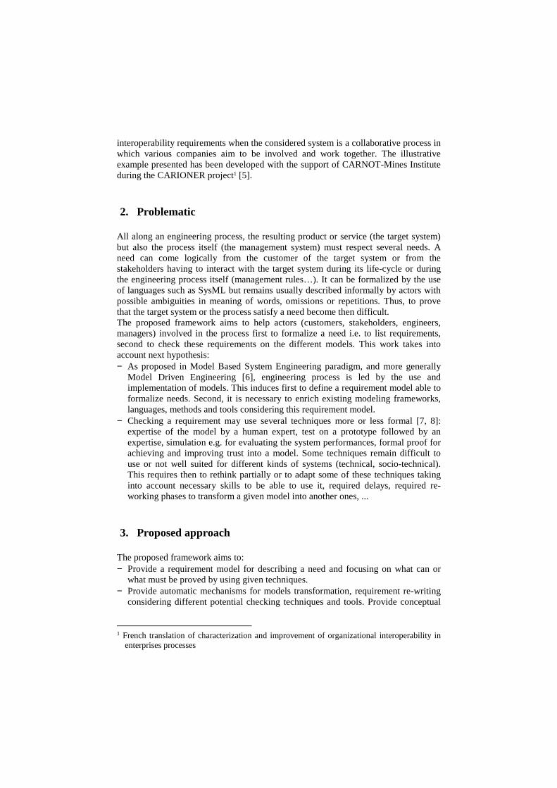
A requirement is considered as an unambiguous, but may be partial, description of the pointed out need concerning customer, stakeholders, process management and models management. Customer describes what the system must do. Stakeholder describes what they require in order to interact with the system. Last, some constraints and rules have to be respected during the process for example when some technological or organizational choices have been made or when reusing existing models. This work takes consideration to the reference model [2] summarized in Figure 1.
Figure 1: requirement reference model [2]
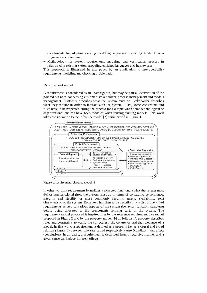
In other words, a requirement formalizes a expected functional (what the system must do) or non-functional (how the system must do in terms of constraint, performance, integrity and stability or more commonly security, safety, availability, etc.) characteristic of the system. Each need has then to be described by a list of identified requirements related to various aspects of the system (behavior, function, structure) before being allocated to the components forming parts of the system. The requirement model proposed is inspired first by the reference requirement tree model proposed in Figure 2 and by the property model [9] as follows. A property describes rules and constraints to verify the correctness, the coherence and the relevance of a model. In this work, a requirement is defined as a property i.e. as a causal and typed relation (Figure 2) between two sets called respectively cause (condition) and effect (conclusion). In all cases, a requirement is described from a recursive manner and a given cause can induce different effects.
node(i.1)
node(i.2)
node(i.k)
node iR
Causal relation
requirementrefinement
ConceptualGraphs
Temporal Logic
Natural language(expertise)
is re-writen into
Simulation language
Test scenarios
CREDI
Requirement description
Conceptual Graphs
node(i.k)
node(i.k.1)
node(i.k.2) R’
node(i.k.n)
Requirementreferencetaxonomy(partial)
Figure 2: requirement reference taxonomy and model
Last logical operators or more complex functions are used for describing the condition under which the requirement have to be checked and the conclusion which is normally expected. It can be: − Temporized: requirement depends from time evolution and concerns system
behavior. − A-temporal: requirement characterizes only the structure or the functional aspect of
the system without taking into account the time. − Simple requirement: cause is empty and effect has to be checked in every case. − Composite requirement: cause and effect are interacting. Requirement specification can be done respecting three cases: − Cause and effect are composed of modeling variables, parameters and predicates
extracted from the model to be verified i.e. model has to be transformed in order to dispose of data which compose it. Requirement cause and effect are described by using the CREDI property model and UPSL [9] (Unified Property Specification language) or the Conceptual Graphs as proposed in [10]. They can be formally checked on the pointed out model by using technique as proposed in [10] or re-written into other formal checking tool inputs languages such as Temporal Logic (for example TCTL in the case of temporized composite or simple requirement if the chosen checking tool is UPPAAL [11]) or simulation scenario description language.
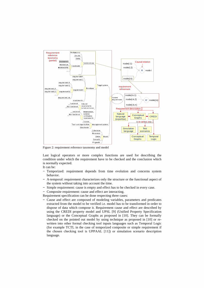
− Cause and effect are composed of other properties allowing then to refine requirements from more complicated or complex ones to most simple ones. Their specification can use then Natural Language to allow users to be more autonomous and creative but this limits usable checking techniques to expertise.
The Figure 3 shows a partial view of the interoperability reference taxonomy proposed in CARIONER project. It takes into account different levels and nature of interoperability problems such as proposed in interoperability reference models defined by the research and industrial communities [12, 13, 14, 15, 16].
Ri.1
Ri
Pi.1- Simple requirement- CREDI- Conceptual Graph- Natural language
Ri - Composite requirement- CREDI- Natural language
Figure 3: interoperability requirements reference taxonomy (partial view)
The Figure 4 shows a very simple example of composite requirement described by using each of the three provided modeling languages.
Other elements of the approach
The conceptual enrichments, model transformation principles and checking mechanisms are rapidly defined and illustrated in the case of CARIONER project as follows:
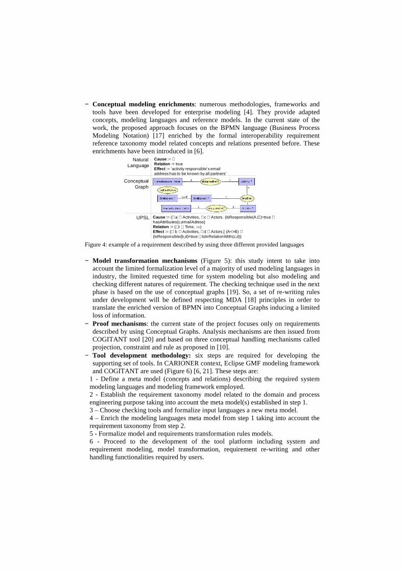
− Conceptual modeling enrichments: numerous methodologies, frameworks and tools have been developed for enterprise modeling [4]. They provide adapted concepts, modeling languages and reference models. In the current state of the work, the proposed approach focuses on the BPMN language (Business Process Modeling Notation) [17] enriched by the formal interoperability requirement reference taxonomy model related concepts and relations presented before. These enrichments have been introduced in [6].
Natural Language
ConceptualGraph
UPSL
Cause := ∅Relation := trueEffect := ‘activity responsible’s email address has to be known by all partners’
Cause := (∃ a ∈ Activities, ∃ c ∈ Actors. (IsResponsible(A,C)=true ∧hasAttributes(c,emailAdress)Relation := (∀t ∈ Time, ⇒)Effect := (∀ b ∈ Activities, ∃ d ∈ Actors.[ (A<>B) ∧(IsResponsible(b,d)=true ∧ IsInRelationWith(c,d))
Figure 4: example of a requirement described by using three different provided languages
− Model transformation mechanisms (Figure 5): this study intent to take into account the limited formalization level of a majority of used modeling languages in industry, the limited requested time for system modeling but also modeling and checking different natures of requirement. The checking technique used in the next phase is based on the use of conceptual graphs [19]. So, a set of re-writing rules under development will be defined respecting MDA [18] principles in order to translate the enriched version of BPMN into Conceptual Graphs inducing a limited loss of information.
− Proof mechanisms: the current state of the project focuses only on requirements described by using Conceptual Graphs. Analysis mechanisms are then issued from COGITANT tool [20] and based on three conceptual handling mechanisms called projection, constraint and rule as proposed in [10].
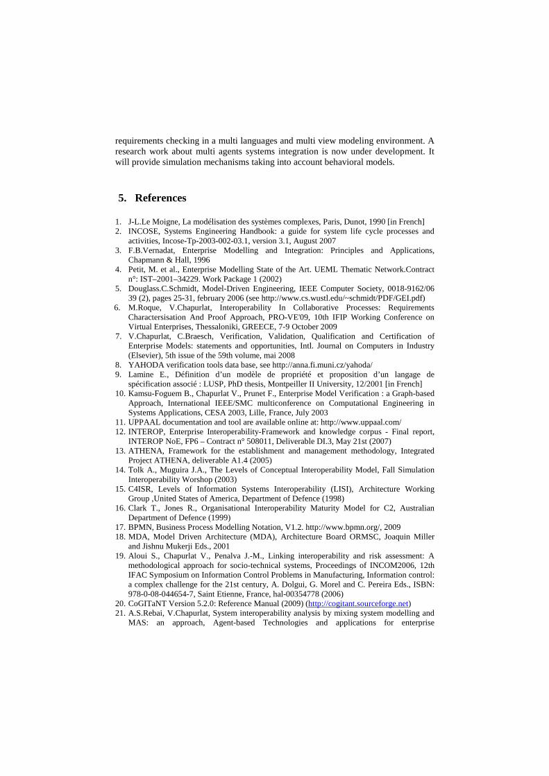
− Tool development methodology: six steps are required for developing the supporting set of tools. In CARIONER context, Eclipse GMF modeling framework and COGITANT are used (Figure 6) [6, 21]. These steps are:
1 - Define a meta model (concepts and relations) describing the required system modeling languages and modeling framework employed. 2 - Establish the requirement taxonomy model related to the domain and process engineering purpose taking into account the meta model(s) established in step 1. 3 – Choose checking tools and formalize input languages a new meta model. 4 – Enrich the modeling languages meta model from step 1 taking into account the requirement taxonomy from step 2. 5 - Formalize model and requirements transformation rules models. 6 - Proceed to the development of the tool platform including system and requirement modeling, model transformation, requirement re-writing and other handling functionalities required by users.
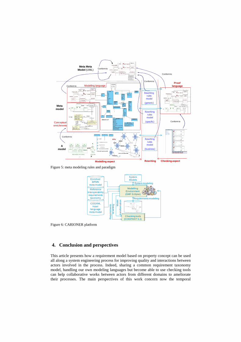
Meta Meta Model (UML)
Meta model
A model
Modelling language
Conceptual enrichments
Conform to
Modelling aspect Checking aspect
Proof language
Conform to
Conform to
Conform to
Rewriting rules
model
(generic)
Rewriting rules
model
(specific)
Rewriting rules
model
(business)
Conform to
Conform to
Rewriting Figure 5: meta modeling rules and paradigm
SystemModels
SystemModels
Mod
eltra
nsfo
rmat
ion
System modeling
Requirements modeling
Req
uire
men
tsre
-writ
ingCOGXML
input language
meta model
ReferenceInteroperabilityrequirements
taxonomy
EnrichedBPMN
meta model
ModellingEnvironment(GMF Eclipse)
Checking tools(COGITANT 5.1)
Figure 6: CARIONER platform
4. Conclusion and perspectives
This article presents how a requirement model based on property concept can be used all along a system engineering process for improving quality and interactions between actors involved in the process. Indeed, sharing a common requirement taxonomy model, handling our own modeling languages but become able to use checking tools can help collaborative works between actors from different domains to ameliorate their processes. The main perspectives of this work concern now the temporal
requirements checking in a multi languages and multi view modeling environment. A research work about multi agents systems integration is now under development. It will provide simulation mechanisms taking into account behavioral models.
5. References
1. J-L.Le Moigne, La modélisation des systèmes complexes, Paris, Dunot, 1990 [in French] 2. INCOSE, Systems Engineering Handbook: a guide for system life cycle processes and
activities, Incose-Tp-2003-002-03.1, version 3.1, August 2007 3. F.B.Vernadat, Enterprise Modelling and Integration: Principles and Applications,
Chapmann & Hall, 1996 4. Petit, M. et al., Enterprise Modelling State of the Art. UEML Thematic Network.Contract
n°: IST–2001–34229. Work Package 1 (2002) 5. Douglass.C.Schmidt, Model-Driven Engineering, IEEE Computer Society, 0018-9162/06
39 (2), pages 25-31, february 2006 (see http://www.cs.wustl.edu/~schmidt/PDF/GEI.pdf) 6. M.Roque, V.Chapurlat, Interoperability In Collaborative Processes: Requirements
Charactersisation And Proof Approach, PRO-VE'09, 10th IFIP Working Conference on Virtual Enterprises, Thessaloniki, GREECE, 7-9 October 2009
7. V.Chapurlat, C.Braesch, Verification, Validation, Qualification and Certification of Enterprise Models: statements and opportunities, Intl. Journal on Computers in Industry (Elsevier), 5th issue of the 59th volume, mai 2008
8. YAHODA verification tools data base, see http://anna.fi.muni.cz/yahoda/ 9. Lamine E., Définition d’un modèle de propriété et proposition d’un langage de
spécification associé : LUSP, PhD thesis, Montpeiller II University, 12/2001 [in French] 10. Kamsu-Foguem B., Chapurlat V., Prunet F., Enterprise Model Verification : a Graph-based
Approach, International IEEE/SMC multiconference on Computational Engineering in Systems Applications, CESA 2003, Lille, France, July 2003
11. UPPAAL documentation and tool are available online at: http://www.uppaal.com/ 12. INTEROP, Enterprise Interoperability-Framework and knowledge corpus - Final report,
INTEROP NoE, FP6 – Contract n° 508011, Deliverable DI.3, May 21st (2007) 13. ATHENA, Framework for the establishment and management methodology, Integrated
Project ATHENA, deliverable A1.4 (2005) 14. Tolk A., Muguira J.A., The Levels of Conceptual Interoperability Model, Fall Simulation
Interoperability Worshop (2003) 15. C4ISR, Levels of Information Systems Interoperability (LISI), Architecture Working
Group ,United States of America, Department of Defence (1998) 16. Clark T., Jones R., Organisational Interoperability Maturity Model for C2, Australian
Department of Defence (1999) 17. BPMN, Business Process Modelling Notation, V1.2. http://www.bpmn.org/, 2009 18. MDA, Model Driven Architecture (MDA), Architecture Board ORMSC, Joaquin Miller
and Jishnu Mukerji Eds., 2001 19. Aloui S., Chapurlat V., Penalva J.-M., Linking interoperability and risk assessment: A
methodological approach for socio-technical systems, Proceedings of INCOM2006, 12th IFAC Symposium on Information Control Problems in Manufacturing, Information control: a complex challenge for the 21st century, A. Dolgui, G. Morel and C. Pereira Eds., ISBN: 978-0-08-044654-7, Saint Etienne, France, hal-00354778 (2006)
20. CoGITaNT Version 5.2.0: Reference Manual (2009) (http://cogitant.sourceforge.net) 21. A.S.Rebai, V.Chapurlat, System interoperability analysis by mixing system modelling and
MAS: an approach, Agent-based Technologies and applications for enterprise

interOPerability (ATOP), Eighth International Joint Conference on Autonomous Agents & Multi-Agent Systems (AAMAS 2009), Budapest, Hungary, May 12 2009