Embed Size (px)
Citation preview
Interoperability between Risk Assessment and SystemDesign for Railway Safety Critical Signalling System
Development ∗
Marielle Petit-DocheSysterel
1090 rue René DescartesParc d’activités de la Duranne13857 Aix-en-Provence cedex [email protected]
Frédéric ThomasObeo
2 route de la Noue - BP 7691193 Gif-sur-Yvette
Fabien BelmonteAlstom Transport
48 rue Albert Dhalenne93482 Saint-Ouen cedex
December 13, 2011
Abstract
The goal of this paper is mainly to show how it would be possible to improve collaboration betweensystem designer and safety assurance manager. Both of them use models since long time but those aregenerally non interoperable because of their different viewpoints on the system.
In this work a tooled methodology has been developed allowing safety engineers to build theirmodels by requesting directly the system design model. Hence, the risk assessment is strongly coupledwith the designer production. Formal methods are used to complete the safety analysis to recordrigorous reasoning about system safety properties proof in a formal model.
1 IntroductionRailway signalling system design on the one hand and risk and safety studies on the other shouldbe strongly coupled. Today collaboration between these two disciplines is performed by a regulatedprocess defined by CENELEC standards (EN 50126 [6], EN 50128 [7], EN 50129 [8]) and imposed bynational authorities. It seems that this process shall be more tooled in order to improve the collabora-tion between safety and system engineers. Safety engineers perform risk assessments by reading andvalidating the work of system engineer. By applying the methodology from the previously mentionedstandards, they aim to identify as exhaustively as possible the accident scenarios and the possible fail-ures of the system and control their mitigation by validating the correct application of the safe devel-opment methodology done by system design (including risk control architecture and error free processdevelopment [4]). It follows that the collaboration between safety analysts and system designers shallallow designers to express a model of the system and the cues of its safe behavior. Today, system de-sign is generally described with textual requirements in large documentation. Safety engineers validatethese designs, by identifying safety related requirements and validating the risk control strategy. Upto now, this validation has been done on textual documentation. The documentation reveals the resultof system design activity and the rationale of the retained solution is not recorded. Furthermore, theresults included in documentation are difficult to reuse especially for the safety engineers. Recently,
∗This paper is funded by the "Systematic Paris Region" cluster in the context of the IMOFIS project. Authors thank the System-atic cluster and all participants of the IMOFIS project. http://www.imofis.org
1
Alstom Transport introduced a model based system engineering methodology to tackle these limita-tions of the textual approach [9]. This approach is made of three viewpoints (Operational, Functionaland Constructional) and supported by the so-called SysML notation.
Moreover, due to the growing complexity of the developed system, it becomes very difficult todemonstrate the behavioral safety of the system. In this domain, formal modeling techniques are help-ful. It allows safety engineers to record rigorous reasoning about system safety properties proof in aformal model. Most of the formal techniques assist the safety engineers by providing formal proofassistant. Such reasoning are clues to justify trustworthiness of the system safety.
The goal of the work presented in this paper is to show how it would be possible to improve collab-oration between system designer and safety assurance manager. Both of them use models since longtime but those are generally non interoperable because of their different viewpoints on the system.Safety engineers use models that describe the dysfunctional behavior of the system in order to assessand better control the risks. Such models refer to specific formalisms: Fault Trees, Event Trees, FailureModes and Effect Analysis (FMEA), see [5]. Until today, to build these models, safety engineer stemfrom documentation of the system.
In this work a tooled methodology has been developed allowing safety engineers to build theirmodels by requesting directly the system design model. Hence, the risk assessment is strongly cou-pled with the designer production. Formal methods are used to complete the safety analysis by ensur-ing that safety requirements are verified on formal models of the system and reinforcing requirementtraceability in regards of safety analysis.
2 MethodologyThe major concern of safety engineers is to insure that the risks are exhaustively covered. To reach thisgoal, two processes are performed during the specification and design phases of the system. One is adeductive strategy where the safety assurance manager shall deduce the causes of accidental scenarios.The second is an inductive strategy, where the safety analyst shall infer the effects of local failures.These two strategies are complementary: causes of failure identified in the deductive risk assessmentare corroborated by the effect given by the inductive risk assessment. Furthermore, problems forgottenin one approach should be seen in the second.
The risk assessment starts with the identification of accidental scenarios. This analysis is calledPreliminary Hazard Analysis (PHA). Based on the definition of accidental scenarios, fault trees arebuilt to identify the causes of the accidents, this is the deductive phase of the risk assessment calledSystem Hazard Analysis - Fault Tree or SHA-FT. Then, the safety analysts take into account the elementaryfailures of the system one by one and identify their effects on the system. This is the inductive processnamed SHA-FMEA.
The PHA is modeled with event tree formalism, the SHA-FT with fault-trees and SHA-FMEAs areserialized within tables. PHA needs to be linked with structural and operational model elements of thesystem design model. And SHA are linked to structural and functional model elements of the systemdesign model.
A domain specific language supported by semi-formal modeling tool for risk assessment has beendeveloped. It is able to communicate with any system engineering modeling language as long as themodel follows the Eclipse Modeling Framework format. The main features are:
• Graphical representation of PHA and SHA;
• One model serialized, many views are available;
• Serialization of the global risk analysis into one fault tree;
• Requests on system design model and references of model element into risk assessment;
• Customization of requests based on system engineering method used in system design (e.g.which model element represents function ?);
• Automatic layout of graphical representation (very usefull for large model);
• Requirements repository and traceability purpose;
3 Formal models for Safety analysisThe use of formal methods to support safety analysis by rigorous reasoning on models of the systemallows to strengthen the processes described in the previous section. Due to the current practice of Bmethod [3] in development of critical software in the railway industries, Event-B [1] a close languagemore suitable for system modeling, with a top-down approach following the system and safety steps
2
has been chosen. Hazard Analyses have highlighted safety requirements, however the usual manualdemonstration that safety requirements are covered by the system can be difficult in some complexcases. Event-B models show that a safety property is verified on a formal model of the system, withsystem functional models and safety properties modeling in the same language. Several elementsimprove the safety analysis:
• Formal models highlight the functional concepts of the system models to ensure safety require-ments;
• Formal proofs follow rigorous mathematical reasoning which ensures that the formal models andthe safety requirements are consistent;
• Event-B approach allows a step by step refinement of the formal models, which can follow thesystem design and the safety analysis refinement steps. Formal models describes the safetyproperties that each functions of each subsystems shall cover. Formal proofs of the model shallstrengthen completeness of the safety requirements during refinement steps;
• Formal model and proof structure shall strengthen fault tree analysis : the proofs highlight thefunctional elements of the system necessary for the mathematical reasoning;
• Formal models shall be animated to be validated in regards to informal system models and safetyanalysis;
• Formal models and proofs can be recorded and reused for an evolution of the system.
4 ToolsFrom a tool provider point of view, there are several challenges to tool up this system engineeringmethodology :
• interoperability : The key idea of the underneath implementation work is to provide a commonframework in which both system engineers can model the system and safety ones can describetheir analyses (PHA, SHA, FMEA, Event B models),
• adaptability : a tool in adequation with both the system and safety expert needs must been pro-vided. It must be a unique tool with several viewpoints : safety and system design viewpoints.
• incrementallity : as any research and development tooling project, the needs are not static butthey evolve.
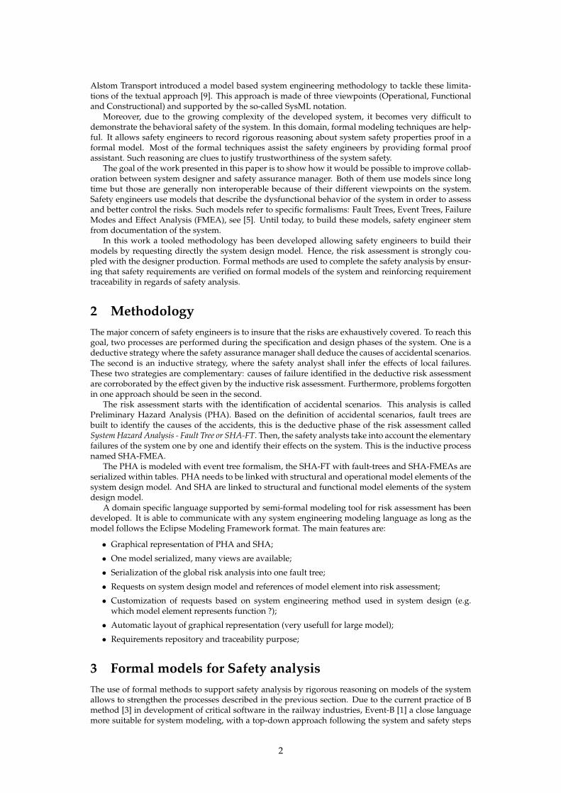
Our current tooling approach is described on the next figure.
To be able to provide interoperability, the Eclipse Modeling framework has been used. This frame-work is opened, available and it is a common adopted framework for many meta-modeling tools basedon Eclipse. It profits us to provide textual, graphical and web-based editors to the engineers. Thosetechnologies allow us to implement specific metamodels for Safety, to reuse SysML implementation 1,to adapt incrementally our tools from the expert reviews, and to extend then to existing tools based onthe same Eclipse Modeling framework (for example with Rodin [2] to edit and validate formal Event-Bmodels). Firstly the required metamodels (safety, requirement management, traceability) is defined,
1the Topcased SysML implementation is used
3
secondly their Java API implementations is generated and finally editors are build upon this new API.Thus, with the viewpoint-based Obeo Designer technology, graphical and tabular views have been de-velopped to describe Safety models. Such a tool allows us to customize a generic model editing tool forexpert needs. It allows one to iteratively describe specific PHA viewpoint in order to adapt the editingframework to our methodology. At the end, all engineers works on the same set of models with severalpoint of views : PHA view, SHA view, Requirement view, System view. Each view represents the samesystem but with a different concern.
Thanks to a common modeling framework and a viewpoint based technology, the risk analysismodels are coupled to the system design model in SysML. Indeed, it allows safety engineers to be fullycompliant with the operational, functional and constructional viewpoints modeled by system design.Moreover, graphical representations of the risk analysis model synchronized with a tabular syntheticrepresentation is provided. The graphical representation is more intuitive for the safety engineers sinceit is based on on-going work [9] for the update of the CENELEC standards (also discussed in MOD-SAFE and MODCONTROL European R&D programs). The tabular representation allows to publishthe result of the risk analysis and also to accelerate the modelling activity when risk analysis is obvious.Finally, Rodin platform [2] has been embedded in the common platform. This allow to link directly for-mal model elements to the safety requirements defined by the safety analyses. Complementary toolshave been developed to check the covering of the requirements by the formal models and to check theproof status.
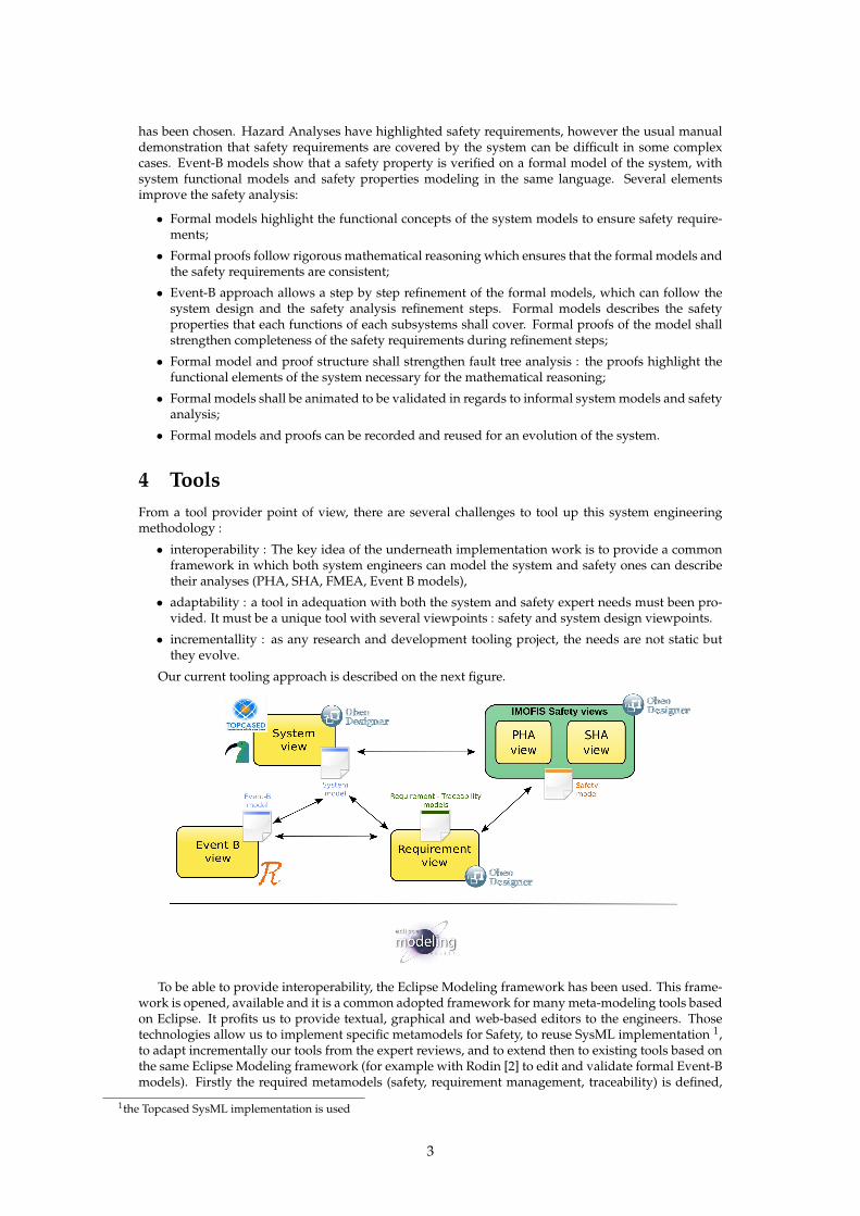
5 ExampleThis approach is going to be described on a small example from the railway domain: apart of a signal-ing system. Such system shall protect against derailment. The objective of our model is to specify theelements of the system to avoid derailment.
The starting point of our approach is a system model, in our case a SysML model, which describesthe structure and functions of the system via block, activity and sequence diagrams.
The following figure gives the block diagram for our example: a CBTC system to operate trainmovements and to protect train against derailment. A CBTC consists of three kinds of subsystems: CBIin charge of interlocking functions, ATP in charge of protection of train functions and ATC in charge ofoperation on train functions.
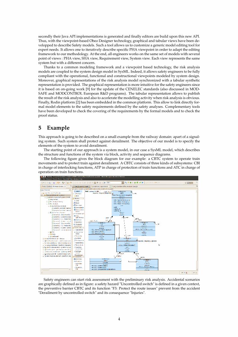
Safety engineers can start risk assessment with the preliminary risk analysis. Accidental scenariosare graphically defined as in figure: a safety hazard "Uncontrolled switch" is defined in a given context,the preventive barrier CBTC and its function "F3: Protect the route issues" prevent from the accident"Derailment by uncontrolled switch" and its consequence "Injuries".
4
In this case, the preventive barrier is constituted of elements of the system. Thanks to tool integra-tion, safety engineers can directly use elements of the SysML model during their analyses.
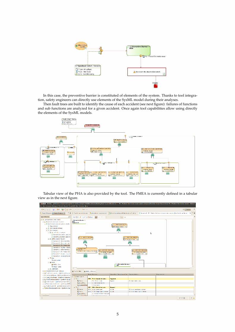
Then fault trees are built to identify the cause of each accident (see next figure): failures of functionsand sub functions are analyzed for a given accident. Once again tool capabilities allow using directlythe elements of the SysML models.
Tabular view of the PHA is also provided by the tool. The FMEA is currently defined in a tabularview as in the next figure.
5
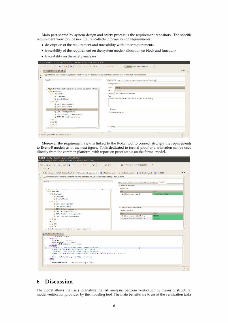
Main part shared by system design and safety process is the requirement repository. The specificrequirement view (on the next figure) collects information on requirements:
• description of the requirement and traceability with other requirements
• traceability of the requirement on the system model (allocation on block and function)
• traceability on the safety analyses
Moreover the requirement view is linked to the Rodin tool to connect strongly the requirementsto Event-B models as in the next figure. Tools dedicated to formal proof and animation can be useddirectly from the common platform, with report on proof status on the formal model.
6 DiscussionThe model allows the users to analyze the risk analysis, perform verification by means of structuralmodel verification provided by the modeling tool. The main benefits are to assist the verification tasks
6
(traceability, consistency and correction) and to put closer the system design engineering and safetyengineering. Formal models strengthen the safety analysis and allow to reuse this analysis. Finally,model driven engineering improves confidence in system and safety analyses while providing reusablemodeling concepts close to the different engineers’ background and thus improve system design andsafety activities.
The framework is going to be extended:
• to other formal methods like AltaRica to complete safety analysis means
• to other tools for requirement and analysis management
• to other activities around critical system development (software development, validation andverification, quality...)
References[1] J-R. Abrial, Modeling in Event-B, Cambridge University Press 2010.
[2] Rodin platform : www.event-b.org
[3] J-R. Abrial, The B-book: assigning programs to meanings, Cambridge University Press 1996.
[4] M. Carnot, C. DaSilva, B. Dehbonei and F. Mejia, Error-free software development for critical sys-tems using the B-Methodology in proceedings of the Third International Symposium of SoftwareReliability Engineering, Research Triangle Park, NC, USA, oct. 1992
[5] Villemeur, Alain, Reliability, availability, maintainability, and safety assessment, J. Wiley, 1992
[6] CENELEC, Railway applications. The specification and demonstration of reliability, availability,maintainability and safety (RAMS), EN50126.
[7] CENELEC, Railway applications. Communications, signalling and processing systems. Softwarefor railway control and protection systems, EN50128.
[8] CENELEC, Railway applications. Communication, signalling and processing systems. Safety re-lated electronic systems for signalling, EN50129.
[9] Belmonte F., Blas A. et Mejia L.-F. And Thomas F., Risk Evaluation in Railway Systems Supported ByModeling Languages and Tools. Lambda-Mu, 17ème Congrès de Maîtrise des Risques et de Sûretéde Fonctionnement. La Rochelle : IMDR, 2010.
7