Embed Size (px)
Citation preview
INTERNSHIP REPORT SUBMISSION
[[G G G
GRAMEENPHONE LTD GAZIPUR SUB CENTRE JHAJHOR,NATIONAL UNIVERSITY GAZIPUR.
Prepared For Dr. M. Mofazzal Hossain Intern Advisor Professor Department of ECE
Prepared By Samiour Rahaman 2011-3-58-028
Date of Submission: April 18, 2016
Acceptance
This internship report is submitted to the Department of Electronics
&Communications Engineering East West University, Dhaka in partial fulfillment
of the requirement for the degree of B.Sc in Electronics & Telecommunications
Engineering under complete supervision of undersigned.
Dr. M. Mofazzal Hossain Md. Dudu Mia
Professor Manager
Department of Electronics &Communications Engineering, Grameenphone LTD.
Gazipur Sub-center
East West University,
Aftabnagar, Dhaka, Bangladesh

1 | P a g e
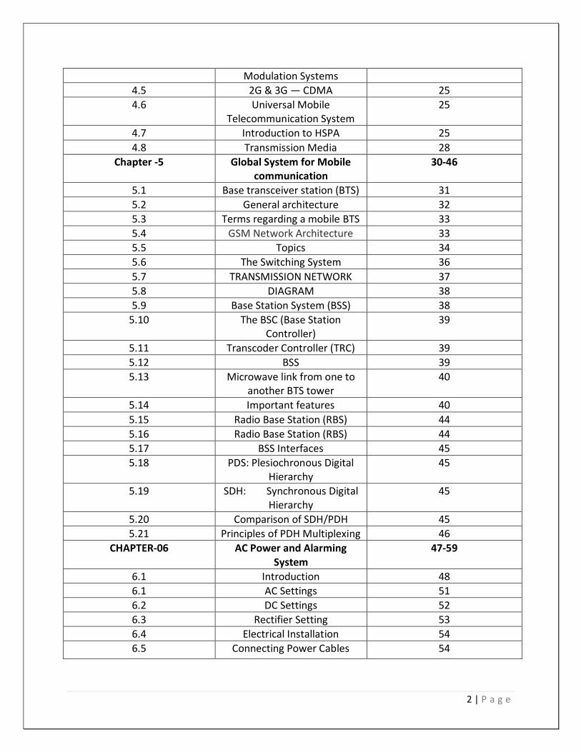
TABLE OF CONTENTS
Serial topic page
Chapter-1 Introduction 1-4
1.1 Origin of the Report 2
1.2 Objective of the Report 2
1.3 Scope of the Report 3
1.4 Methodology 3
1.5 Limitation 4
Chapter-02 Background of the Organization
5-10
2.1 An Overview of the Organization
6
2.2 Share Holders 6
2.3 Telenor Mobile Communications
7
2.4 Grameen Telecom 8
2.5 Company Mission 8
2.6 Company’s Objectives 9
2.7 Company’s strategy 9
2.8 Company’s Value 10
Chapter -3 Microwave link PNMS (Paso link Network Management
System)
11-21
3.1 System description 12
3.2 Functional description and components
12
3.3 IDU and ODU Components 15
3.4 IDU functional description 15
3.5 ODUFunctionalDescription 17
3.6 IDU (Indoor Unit) 19
3.7 900 MRFU 19
3.8 1800 MRFU 20
3.9 2100 MRFU 20
3.10 DVS 20
3.11 Antenna Configurations 21
Chapter -04 3G Network 22-29
4.1 3G services 23
4.2 Benefit of 3G 23
4.3 3G Different from 2G 23
4.4 Technological Evaluation of 24
2 | P a g e
Modulation Systems
4.5 2G & 3G — CDMA 25
4.6 Universal Mobile Telecommunication System
25
4.7 Introduction to HSPA 25
4.8 Transmission Media 28
Chapter -5 Global System for Mobile communication
30-46
5.1 Base transceiver station (BTS) 31
5.2 General architecture 32
5.3 Terms regarding a mobile BTS 33
5.4 GSM Network Architecture 33
5.5 Topics 34
5.6 The Switching System 36
5.7 TRANSMISSION NETWORK 37
5.8 DIAGRAM 38
5.9 Base Station System (BSS) 38
5.10 The BSC (Base Station Controller)
39
5.11 Transcoder Controller (TRC) 39
5.12 BSS 39
5.13 Microwave link from one to another BTS tower
40
5.14 Important features 40
5.15 Radio Base Station (RBS) 44
5.16 Radio Base Station (RBS) 44
5.17 BSS Interfaces 45
5.18 PDS: Plesiochronous Digital Hierarchy
45
5.19 SDH: Synchronous Digital Hierarchy
45
5.20 Comparison of SDH/PDH 45
5.21 Principles of PDH Multiplexing 46
CHAPTER-06 AC Power and Alarming System
47-59
6.1 Introduction 48
6.1 AC Settings 51
6.2 DC Settings 52
6.3 Rectifier Setting 53
6.4 Electrical Installation 54
6.5 Connecting Power Cables 54

3 | P a g e
6.6 Alarming system
55
6.7 I n s t a l l a t i o n o f S e n s o r 55
6.8 Smoke sensor 56
6.9 Operations: 56
6.10 Alarm Handling 57
6.11 CONCLUSION 59
Chapter-7 Reference 60

4 | P a g e
Chapter-1

5 | P a g e
Introduction
Telecommunication is the transmission of information, over significant distances, for the
purpose of communication. Today the globe is a village and telecommunication has become a
necessity to people’s life. Moreover, telecommunication has started introducing some
diversified areas with the help of its mobile network. Nowadays, people cannot think without
mobile phone. Many people depend on it for their ultimate connectivity. It has become a part
of people’s day to day life. Mobile technology is presently providing various cheap solutions in
people’s daily life. Information technology enables telecom companies to provide economic
solutions with a very cheap and easily available access, which was costly earlier and not
accessible to some extent. Using a mobile phone has become a common measure of
communication in our country. From a rickshaw puller to a higher official, everyone owns a
mobile phone. The number of mobile phone user is increasing day by day. So our country has
become an attractive market for mobile operators. Grameenphone is one of the leading mobile
operators in our country who have seen this great potential.
1.1 Origin of the Report
Internships provide an opportunity for students to link theory with practice and further serve as a
temporary labor pool for those organizations that have committed to participate in the internship
program. The internship program has following purposes:
It provides a student with a practical real world experience in the public or nonprofit sector
before entering into a job market. Such experience not only increases students‟ job prospects, but
also teaches what is expected in terms of professional behavior.
It enables a student to develop important skills which cannot be taught in the classroom.
It enables a student to compare theoretical ideas learned in the classroom within the world of work.
It permits a student to apply the technical skills learned in the classroom to real world problems.
I have prepared this report after the three months internship program in Grameenphone ltd.
This report is based on “Base Transceiver station(BTS) at Grameenphone. I have also covered
information regarding the organizational overview and what I did and learned everyday in
Grameenphone Ltd.
1.2 Objective of the Report There are two kinds of objectives of the report. They are:
Broad Objective
6 | P a g e
Specific Objective
1.2.1 Broad Objective The main objective of the report has been done to show the total working procedure of Base
Transceiver Station, fibber, etc at Grameenphone Ltd.
1.2.2 Specific Objective
The specific objectives of this internship report are:
To focus on the overview of Grameenphone Ltd
To focus on the work environment, employee behavior and have a quick glimpse of the
corporate culture of Grameenphone Ltd.
To focus on the recruitment and selection process of Grameenphone and learn how this
process takes place in reality
1.3 Scope of the Report
This study was undertaken aiming to know about the operation and maintenance of Base
Transceiver station(BTS). The scope of this study includes reviewing the technical, commercial
and customer service quality of Grameenphone and identifying tolls and techniques used by
Grameenphone to achieve remarkable performance level. Moreover, I have been worked under
system operation and system protection unit in Grameenphone and thus provide me the way to
get myself familiarized with the official environment for the first time. I had an experience by
working in the department. I had the opportunity to have close view of their activities. The area
of concentration of this report is confined in investigating different aspect of implementation
technical division
1.4 Methodology
This report was prepared in a systematic manner. My academic supervisor assigned the topic of
the report. All the information was collected from two sources:
1.4.1 Primary Sources My supervisor in Grameenphone Ltd helped me a lot in preparing the report. I interview him
face to face, he gave me all the necessary information that I needed. In addition I have also
gathered information by observing and by participating in recruitment and selection process.
7 | P a g e
1.4.2 Secondary Sources
I browsed the internet for as much information I could get. From the internet I got the
background information of the company
1.5 Limitation
Disclosing of much information is confidential. For that reason I was unable to disclose forms
that they use in the time of joining or what kind of information they keep in their personnel file.
In the following chapter I have given a glimpse of GP - their mission, vision, principles, purpose,
products, shareholders etc. This will help us to know about Grameenphone in a broader way.

8 | P a g e
Chapter-02
Background of the Organization
9 | P a g e
2.1 An Overview of the Organization
Grameenphone Ltd., the largest telecommunications service provider in Bangladesh, received its
operating license in November 1996 and started its operation from March 26, 1997, the
Independence Day of Bangladesh.Grameenphone provides services to rural and urban customers
across Bangladesh, where mobile telephony is acknowledged as a significant driver of socio-
economic development, both for individual and the nation.
Grameenphone launched a new, refreshed logo in November 2006.
The logo expresses the values Grameenphone is known for: trust,
reliability, quality and constant progress. It also signals the
company's continued focus on securing the best possible
communications services for its customers. It reflects the continuous
efforts to evolve the organization and its dynamics to serve the
customers even better in the future.Now, after 18 years of successful operations, Grameenphone
is the largest mobile phone service provider in Bangladesh, with more than 55 million
subscribers as June 2015. The Company was successfully listed on the stock exchanges in
November 2009- after completion of the largest IPO in the history of the Bangladesh capital
market.
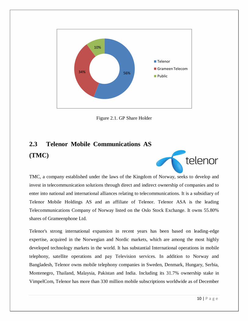
2.2 Share Holders
The shareholding structure comprises of mainly two sponsor Shareholders namely Telenor
Mobile Communications AS (55.80%) and Grameen Telecom (34.20%). The rest 10.00%
shareholding includes General Public & other Institutions.
10 | P a g e
Figure 2.1. GP Share Holder
2.3 Telenor Mobile Communications AS
(TMC)
TMC, a company established under the laws of the Kingdom of Norway, seeks to develop and
invest in telecommunication solutions through direct and indirect ownership of companies and to
enter into national and international alliances relating to telecommunications. It is a subsidiary of
Telenor Mobile Holdings AS and an affiliate of Telenor. Telenor ASA is the leading
Telecommunications Company of Norway listed on the Oslo Stock Exchange. It owns 55.80%
shares of Grameenphone Ltd.
Telenor's strong international expansion in recent years has been based on leading-edge
expertise, acquired in the Norwegian and Nordic markets, which are among the most highly
developed technology markets in the world. It has substantial International operations in mobile
telephony, satellite operations and pay Television services. In addition to Norway and
Bangladesh, Telenor owns mobile telephony companies in Sweden, Denmark, Hungary, Serbia,
Montenegro, Thailand, Malaysia, Pakistan and India. Including its 31.7% ownership stake in
VimpelCom, Telenor has more than 330 million mobile subscriptions worldwide as of December
56%34%
10%
Telenor
Grameen Telecom
Public

11 | P a g e
31, 2011.Telenor uses the expertise it has gained in its home and international markets for the
development of emerging markets like Bangladesh.As part of the conversion of Grameenphone
from a private limited to a public limited company, Telenor Mobile Communications AS
transferred 10 shares each on May 31, 2007 to its three (3) affiliate organizations namely Nye
Telenor Mobile Communications II AS, Norway; Telenor Asia Pte. Ltd., Singapore; and Nye
Telenor Mobile Communications III AS, Norway.
2.4 Grameen Telecom (GTC)
Grameen Telecom, which owns 34.20% of the shares of
Grameenphone, is a not-for-profit company in Bangladesh
established by Professor Muhammad Yunus, winner of the
Nobel Peace Prize 2006.GTC‟s mandate is to provide easy access to GSM cellular services in
rural Bangladesh and create new opportunities for income generation through self-employment
by providing villagers, mostly to the poor rural women with access to modern information and
communication-based technologies.Grameen Telecom, with its field network, administers the
Village Phone Program, through which Grameenphone provides its services to the fast growing
rural customers, Grameen Telecom trains the operators and handles all service-related
issues.GTC has been acclaimed for the innovative Village Phone Program. GTC & its Chairman
Nobel Peace prize laureate Professor Muhammad Yunus have received several awards which
include; First ITU World information Society Award in 2005; PetersburgPrize for Use of the IT
to improve Poor People‟s Lives” in 2004; GSM Association Award for “GSM in Community
Service” in 2000.As part of the conversion of Grameenphone from a private limited to a public
limited company, Grameen Telecom transferred share each on May 31, 2007 to its two affiliate
organizations namely GrameenKalyan and Grameen Shakti.
2.4 Grameen Telecom
Grameenphone‟s vision is “We’re here to help.” That means Grameenphone Ltd. is always
there to help the customers get the full assistance of communications services in their daily lives.
They want to make it simple for the customers to get what and when they want it.
12 | P a g e
2.5 Company Mission
The mission of Grameenphone Ltd is to deliver reliable, widespread, convenient mobile and cost
effective telephone services to the people in Bangladesh irrespective of where they live .They are
providing a total communication solution to its customers. To do this, the service advance of
Grameenphone has extensively developed over the last few years. Grameenphone
subscribers now enjoy all the modern data communication and content services. Mobile office,
internet access, MMS and modern music and download services are available through the
nationwide EDGE enabled network
2.6 Company’s Objectives
Grameenphone (GP) has been established to provide high-quality GSM cellular service at
affordable prices. Grameenphone has a dual purpose: To receive an economic return on its
investment
To contribute to the economic development of Bangladesh where
telecommunications can play a critical role The Company has developed its strategies so that it
earns healthy returns for its share holdersand at the same time, contributes to genuine
development of the country. This is why Grameenphone, in collaboration with Grameen Bank
and Grameen Telecom, is aiming to place one phone in each village to contribute significantly to
the economic benefit of the poor. It is on the way to get a total uprising in the telecommunication
field.
2.7 Company’s strategy
Grameenphone Limited's strategy was to effectively become the second national operator in
Bangladesh. Instead of focusing on a high-end, niche market; it pursued a low tariff strategy
designed to compete directly with BTTB
13 | P a g e
2.8 Company’s Value
2.9.1 Make it Easy
Grameenphone believes that they are sensible. Everything they create is easy to appreciate and
use as they never fail to remember that they are trying to make their customers' lives easier.
2.9.2 Be Inspiring
Grameenphone believes that they are imaginative. They convey energy and thoughts to their
network. Grameenphone wants to be a collaborator in the progress of our society. They are
passionate about our business, customers and country.
2.9.3 Keep Promise
Everything Grameenphone set out to do should work. If it does not, they are there to putting
right. They are about delivery, not over promising - actions not words.
2.9.4 Be Respectful
Grameenphone shows acknowledgement and admiration the local culture. They are courteous
and professional in regard to all interactions, both internally and externally. They are open,
helpful and friendly.
6.
14 | P a g e
Chapter -3
Microwave link PNMS (Paso link Network
Management System)
15 | P a g e
3.1 System description
This chapter gives the detailed description of the equipment features and subsystems that have
not been given in the previous part. Information given in the following is:
1. Functional description and components 2. Control subsystem hardware architecture 3. IDU functional description 4. Protection schemes 5. ODU functional description
3.2 Functional description and components
This paragraph sums–up the equipment functions and defines its components from the SW
point of view:
1. Functions and configurations
2. IDU and ODU Components:
a. IDU
b. ODU
c. Allowed Equipment Types
d. Remote Inventory Management
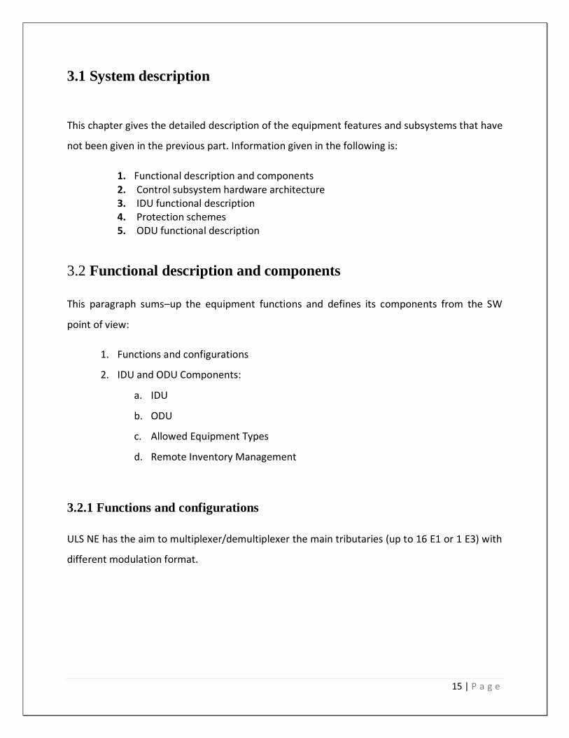
3.2.1 Functions and configurations
ULS NE has the aim to multiplexer/demultiplexer the main tributaries (up to 16 E1 or 1 E3) with
different modulation format.
16 | P a g e
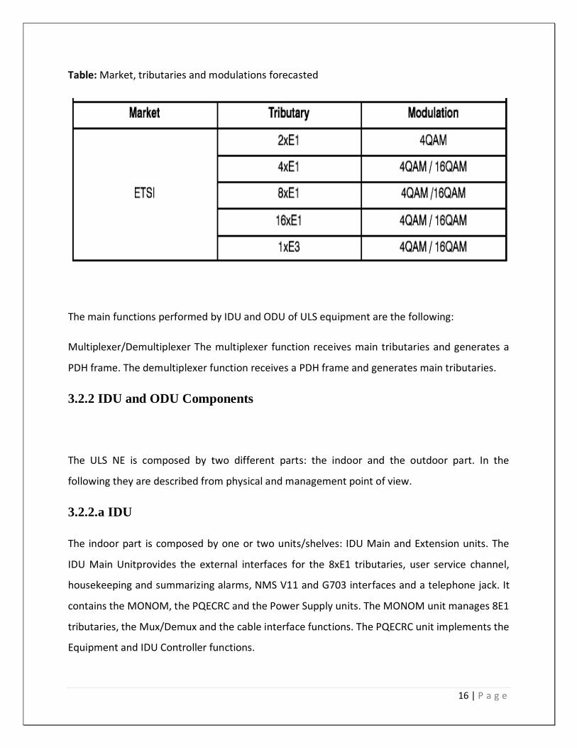
Table: Market, tributaries and modulations forecasted
The main functions performed by IDU and ODU of ULS equipment are the following:
Multiplexer/Demultiplexer The multiplexer function receives main tributaries and generates a
PDH frame. The demultiplexer function receives a PDH frame and generates main tributaries.
3.2.2 IDU and ODU Components
The ULS NE is composed by two different parts: the indoor and the outdoor part. In the
following they are described from physical and management point of view.
3.2.2.a IDU
The indoor part is composed by one or two units/shelves: IDU Main and Extension units. The
IDU Main Unitprovides the external interfaces for the 8xE1 tributaries, user service channel,
housekeeping and summarizing alarms, NMS V11 and G703 interfaces and a telephone jack. It
contains the MONOM, the PQECRC and the Power Supply units. The MONOM unit manages 8E1
tributaries, the Mux/Demux and the cable interface functions. The PQECRC unit implements the
Equipment and IDU Controller functions.
17 | P a g e
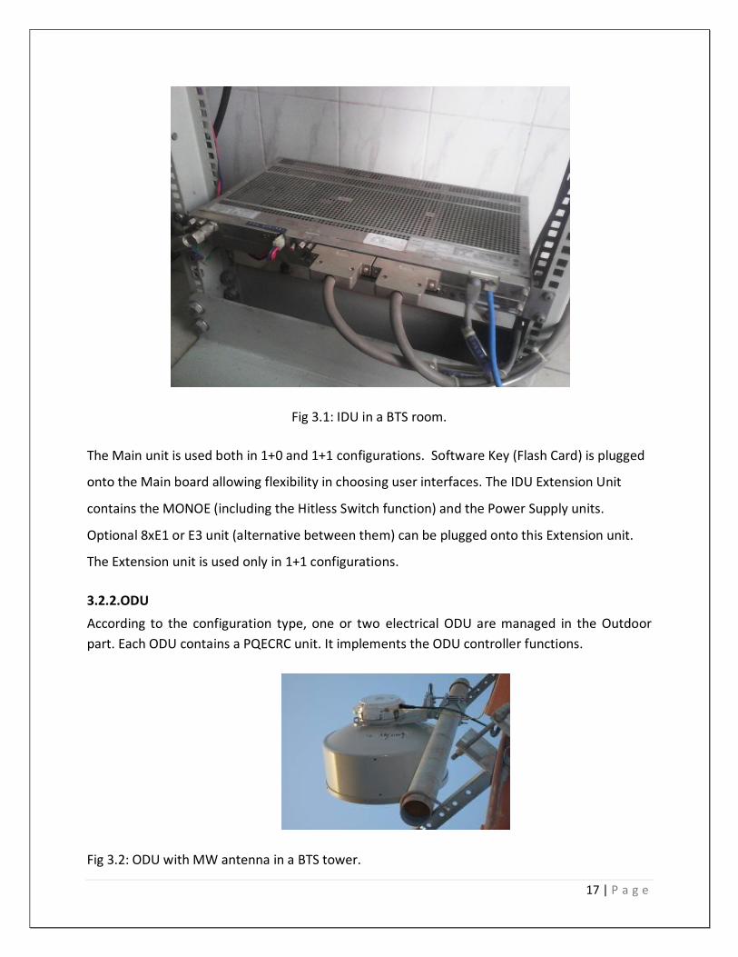
Fig 3.1: IDU in a BTS room.
The Main unit is used both in 1+0 and 1+1 configurations. Software Key (Flash Card) is plugged
onto the Main board allowing flexibility in choosing user interfaces. The IDU Extension Unit
contains the MONOE (including the Hitless Switch function) and the Power Supply units.
Optional 8xE1 or E3 unit (alternative between them) can be plugged onto this Extension unit.
The Extension unit is used only in 1+1 configurations.
3.2.2.ODU
According to the configuration type, one or two electrical ODU are managed in the Outdoor
part. Each ODU contains a PQECRC unit. It implements the ODU controller functions.
Fig 3.2: ODU with MW antenna in a BTS tower.

18 | P a g e
3.3 ODU Supervisory Unit
The ODUC has in charge the PMMF/U–ODU. This function requires a real time processing of the
data coming from the ODU ASIC. The ODUC has the aim to provide a uniform interface towards
the EC avoiding an EC dependency from the ODU HW.
Inside the IDU there is one single internal communication interface: the IDU SPI interface.
3.4 IDU functional description
3.4.1 Introduction
The Indoor Unit (IDU) performs all customer interface requirements both as voice and data:
I. NxE1/E3 for ETSI market
II. NxDS1/DS3 for ANSI market
III. EOW
IV. Service channels
V. OS–TMN
And feeds the Outdoor Unit (ODU) via a single coaxial cable carrying:
VI. Base Band Transmission Signal (from IDU to ODU)
VII. Base Band Receiver Signal (from ODU to IDU)
VIII. ODU Supply Voltage
The IDU is available in 2 configurations:
1+0 IDU
3.4.2 IDU Main Unit
As shown in Figurer, the components of the IDU Main unit are:
The MONOM unit (the motherboard), which includes:
The interface for 8E1 tributaries and for all the other channels whose connectors
are present on its front plate
19 | P a g e
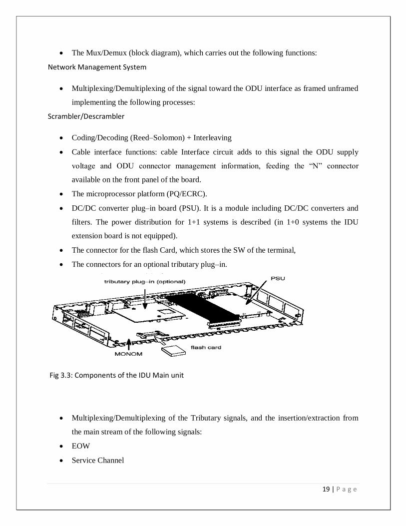
The Mux/Demux (block diagram), which carries out the following functions:
Network Management System
Multiplexing/Demultiplexing of the signal toward the ODU interface as framed unframed
implementing the following processes:
Scrambler/Descrambler
Coding/Decoding (Reed–Solomon) + Interleaving
Cable interface functions: cable Interface circuit adds to this signal the ODU supply
voltage and ODU connector management information, feeding the “N” connector
available on the front panel of the board.
The microprocessor platform (PQ/ECRC).
DC/DC converter plug–in board (PSU). It is a module including DC/DC converters and
filters. The power distribution for 1+1 systems is described (in 1+0 systems the IDU
extension board is not equipped).
The connector for the flash Card, which stores the SW of the terminal,
The connectors for an optional tributary plug–in.
Fig 3.3: Components of the IDU Main unit
Multiplexing/Demultiplexing of the Tributary signals, and the insertion/extraction from
the main stream of the following signals:
EOW
Service Channel
20 | P a g e
3.4.3 IDU Power Supply Unit
The PSU is a plug–in of the Main mono–board and Extension mono–board. The PSU is
functionally made up of three main blocks Input Section (IS): common to both LVS and HVS
Low Voltage Section (LVS): for internal IDU power supply
High Voltage Section (HVS): for external ODU power supply
And two auxiliary blocks:
Alarm generation: for external supervision
Remote Inventory: for factory identification
The following versions are foreseen:
a. Floating (48–60) V nom. ±20%;
b. Floating 24V nom. ±20%
Input is designed as floating, meaning that either plus or minus of battery input could be
externally connected to ground input, without affecting any required characteristic or
functionality. Following alarms are provided by the PSU Unit and connected to spider’s pins:
Fail IS: IS not working properly or standing input voltage outside the normal service
range
Fail_LVS: Low Voltage Section (+3,3V and 1,5V) not working properly
3.5 ODU Functional Description
The Outdoor unit is produced of the following sections:
1. Modem and IF section
2. Local Oscillator
3. Tx IF section
4. Rx IF section
5. RF section
6. Diplexer
7. DC/DC converter
:
21 | P a g e
3.5.1 Modem and IF Section
Cable interface:
The cable interface between IDU and ODU allows carrying over the coaxial cable:
The transmit and receive data streams (and interface these streams to the modem on ODU side),
The control signals and service channel. The DC power supply from the IDU to the ODU
3.5.2 Modem section
The modem section performs the 4 QAM or 16 QAM modulation and demodulation functions,
with embedded digital filtering and equalization. It also incorporates the analog to digital and
digital to analog conversions.
3.5.3 IF section
The IF section incorporates the quadrature modulator (respectively the quadrature demodulator)
for the up–conversion (respectively down–conversion) to a transmit IF (respectively from a
receive IF). It performs base–band filtering and AGC. IF frequencies are variable in order to
cope with all frequency spacing.
3.5.4 Local Oscillator
There is one single Local Oscillator both for transmit and receive RF units.It is electronically
tuned, by software, to the requested frequency, providing frequency agility over a quarter of the
frequency plan.
3.5.5 Diplexer
The Diplexer separates transmit and receive signals at the RF antenna port.
22 | P a g e
3.5.6 DC/DC Converter
The DC/DC Converter provides the DC/DC conversion to generate the secondary voltages from
the remote supply voltage. It interfaces with all active modules of the transceiver.
3.6 IDU (Indoor Unit)
The IDU incorporates the base–band processing and offers tributaries interfaces as well as
service channel and supervision. The IDU is frequency–independent.
As shown in figure up to 2 sub–racks (each of them being 1U high) are used as basic elements
to build the following configurations:
1+0 this configurations: includes one main IDU unit (height 1U)
1+1 this configurations: includes one main IDU unit (height 1U) and one Extension IDU
unit (height 1U).
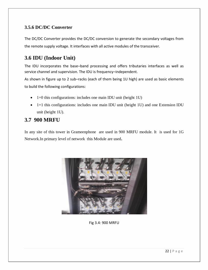
3.7 900 MRFU
In any site of this tower in Grameenphone are used in 900 MRFU module. It is used for 1G
Network.In primary level of network this Module are used.
Fig 3.4: 900 MRFU

23 | P a g e
3.8. 1800 MRFU
In 1800 MRFU Module are used for 2G Network. For adding this kinds of module the network
are increasing from 1G Network.
3.9. 2100 MRFU
In 2100 MRFU are used for 3G.Maximum location of our country are coverage of 3G Network.
3.10 DVS
DC ventilation system (DVS) is used in every BTS room. It is used for controlling the room
temperature .some times in our country the temperature are increased so much. For this
reason it is used so that the temperature are decrease .For protected this equipments of BTS
room this DVS contribute lot of work.
Fig 3.4: DVS at BTS room
24 | P a g e
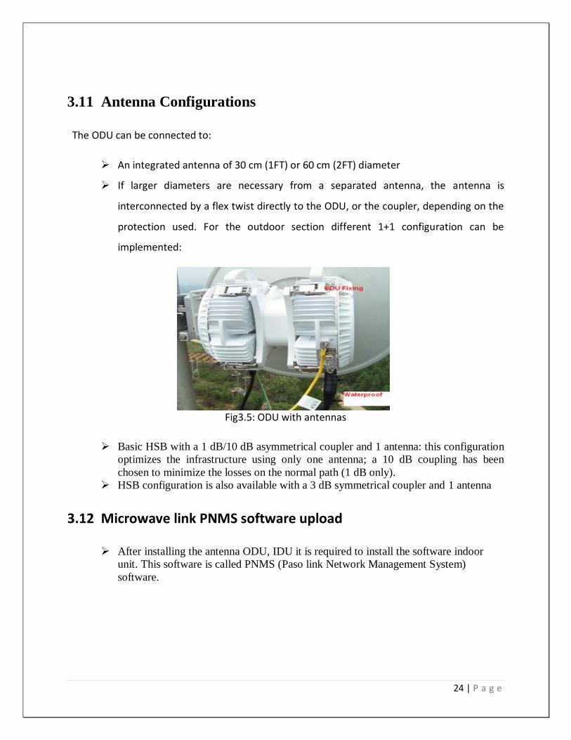
3.11 Antenna Configurations
The ODU can be connected to:
An integrated antenna of 30 cm (1FT) or 60 cm (2FT) diameter
If larger diameters are necessary from a separated antenna, the antenna is
interconnected by a flex twist directly to the ODU, or the coupler, depending on the
protection used. For the outdoor section different 1+1 configuration can be
implemented:
Fig3.5: ODU with antennas
Basic HSB with a 1 dB/10 dB asymmetrical coupler and 1 antenna: this configuration
optimizes the infrastructure using only one antenna; a 10 dB coupling has been
chosen to minimize the losses on the normal path (1 dB only).
HSB configuration is also available with a 3 dB symmetrical coupler and 1 antenna
3.12 Microwave link PNMS software upload
After installing the antenna ODU, IDU it is required to install the software indoor
unit. This software is called PNMS (Paso link Network Management System)
software.
25 | P a g e
Chapter -04
3G Network
26 | P a g e
4.1 3G services
3G refers to the third generation of wireless technology.
The 3G network enabled you to make video calls, watch live TV, access high speed internet and
enjoy live streaming for an enhanced mobile internet experience
4.2 Benefit of 3G
With 3G you should be able to do the following
Multimedia streaming & download
High speed mobile broadband
Video calling
Live streaming TV
Download of large email attachments very fast
Video call conference
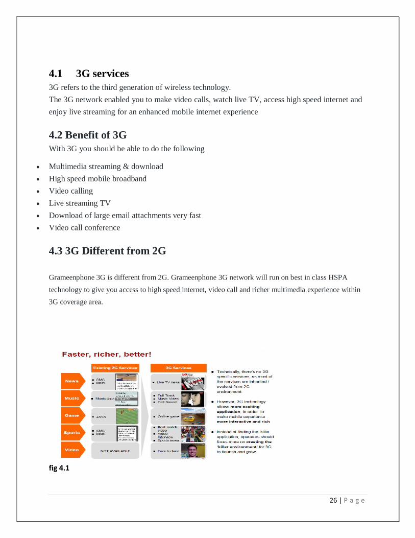
4.3 3G Different from 2G
Grameenphone 3G is different from 2G. Grameenphone 3G network will run on best in class HSPA
technology to give you access to high speed internet, video call and richer multimedia experience within
3G coverage area.
fig 4.1
27 | P a g e
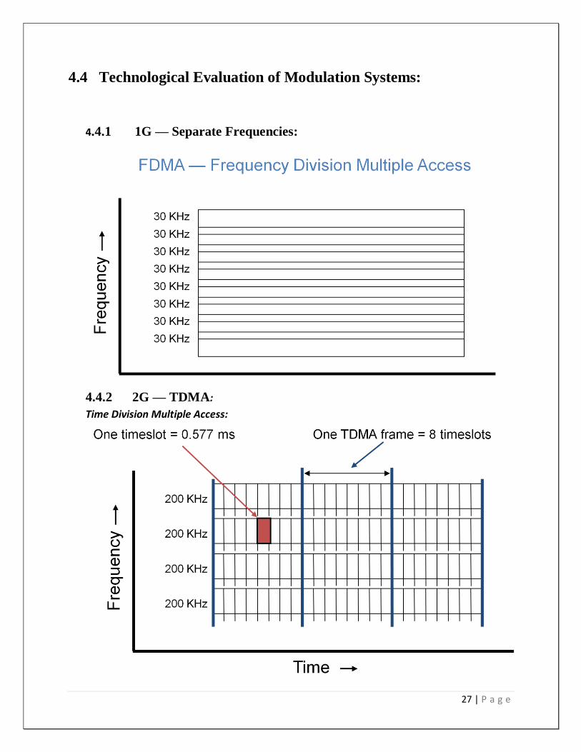
4.4 Technological Evaluation of Modulation Systems:
4.4.1 1G — Separate Frequencies:
4.4.2 2G — TDMA:
Time Division Multiple Access:

28 | P a g e
4.5 2G & 3G — CDMA
Code Division Multiple Access:
• Spread spectrum modulation
– Originally developed for the military
– Resists jamming and many kinds of interference
– Coded modulation hidden from those w/o the code
• All users share same (large) block of spectrum
– One for one frequency reuse
– Soft handoffs possible
• Almost all accepted 3G radio standards are based on CDMA
– CDMA2000, W-CDMA and TD-SCDMA
4.6 Universal Mobile Telecommunication System(UMTS)
• ETSI/ARIB Proposal of deploying WCDMA is largely accepted by vendors like Ericsson and
operators like NTTDoCoMO
• It uses GSM Mobile Application Part(MAP) which is a SS7 protocol communicating between
3G and 2G service
• It enables that 2G operation will not be hampered for deployment of 3G
• This proposal is called UMTS and the radio part is called UTRAN(UMTS Territorial Radio
Access Network).
• Later a global umbrella for UMTS and CDMA was developed which is called IMT-2000
√ IMT-direct spread/ UMTS-FDD
√ IMT-Multicarrier/CDMA 2000
4.7 Introduction to HSDPA
29 | P a g e
4.7.1 HSDPA Concept:
• Max Throughput – 14.4 Mbps
• HS-DSCH
• SF-16
• QPSK, 16QAM
• TTI=2 ms
• HARQ
• New Channel: HS-SCCH, HS-DPCCH
• No Fast Power Control
30 | P a g e
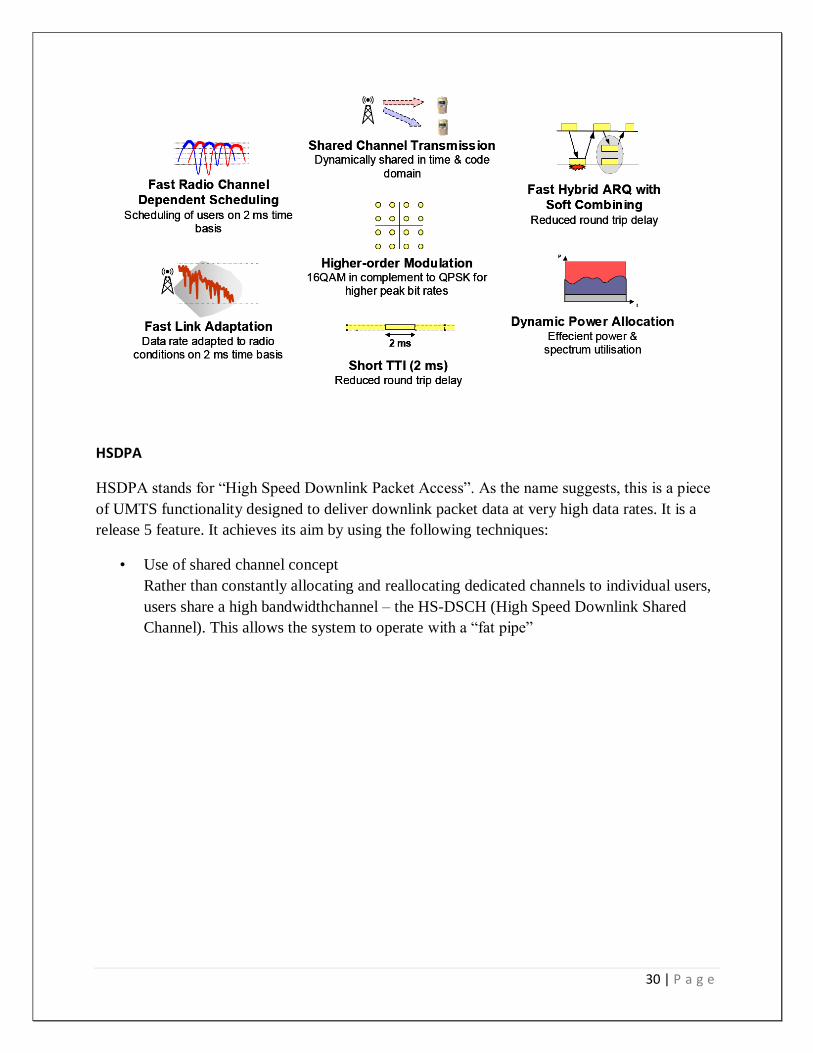
HSDPA
HSDPA stands for “High Speed Downlink Packet Access”. As the name suggests, this is a piece
of UMTS functionality designed to deliver downlink packet data at very high data rates. It is a
release 5 feature. It achieves its aim by using the following techniques:
• Use of shared channel concept
Rather than constantly allocating and reallocating dedicated channels to individual users,
users share a high bandwidthchannel – the HS-DSCH (High Speed Downlink Shared
Channel). This allows the system to operate with a “fat pipe”
31 | P a g e
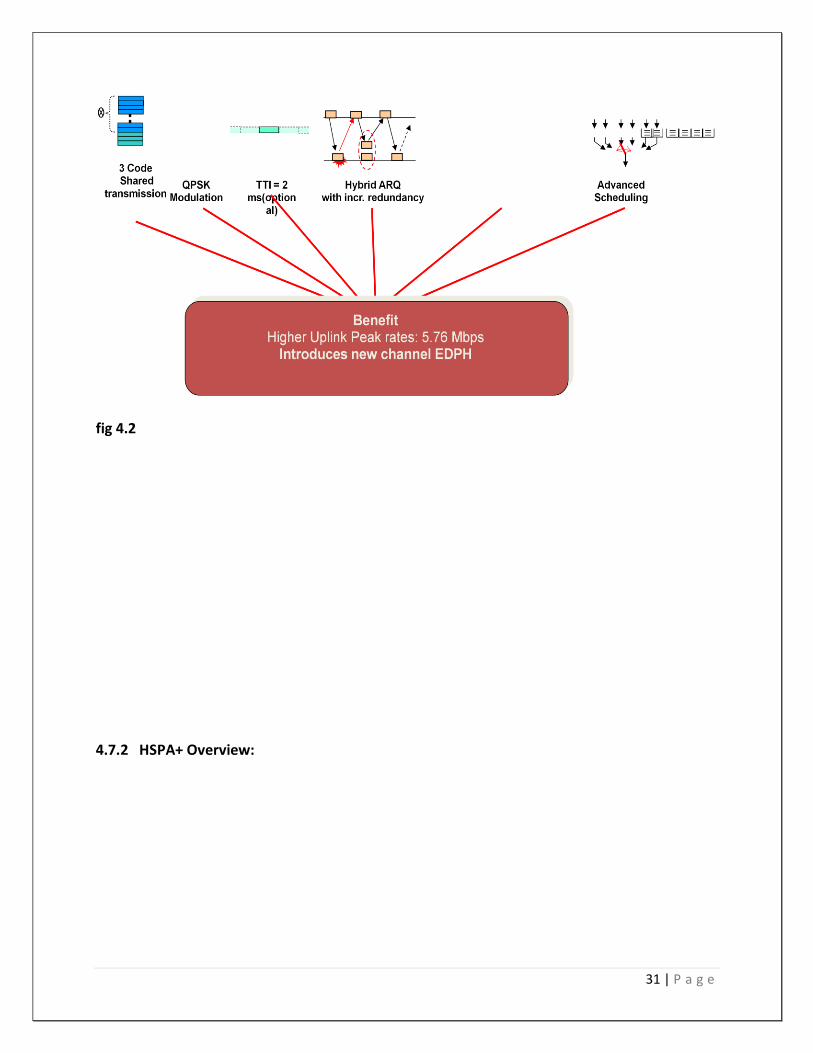
fig 4.2
4.7.2 HSPA+ Overview:
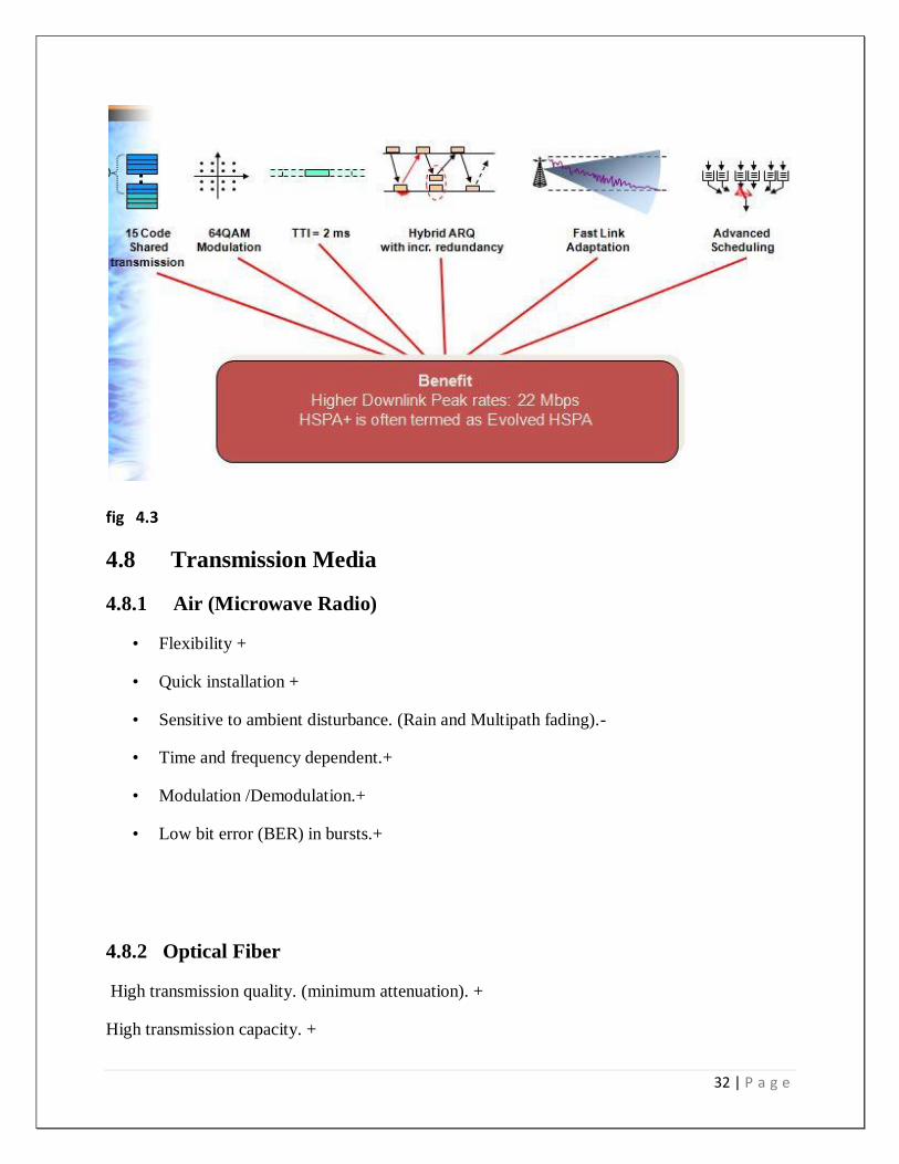
32 | P a g e
fig 4.3
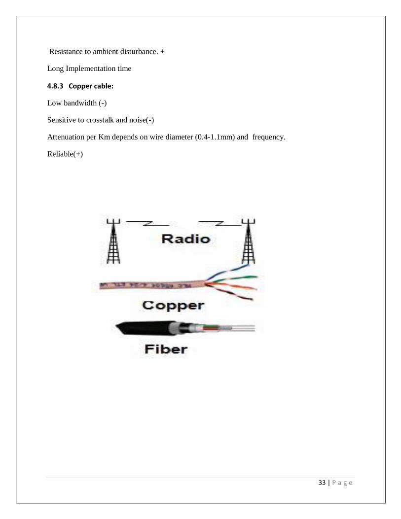
4.8 Transmission Media
4.8.1 Air (Microwave Radio)
• Flexibility +
• Quick installation +
• Sensitive to ambient disturbance. (Rain and Multipath fading).-
• Time and frequency dependent.+
• Modulation /Demodulation.+
• Low bit error (BER) in bursts.+
4.8.2 Optical Fiber
High transmission quality. (minimum attenuation). +
High transmission capacity. +
33 | P a g e
Resistance to ambient disturbance. +
Long Implementation time
4.8.3 Copper cable:
Low bandwidth (-)
Sensitive to crosstalk and noise(-)
Attenuation per Km depends on wire diameter (0.4-1.1mm) and frequency.
Reliable(+)
34 | P a g e
Chapter -5
Global System for Mobile communication
5.1 Base transceiver station (BTS)
5.1 Introduction:
35 | P a g e
A base transceiver station (BTS) is a piece of equipment that facilitates, wire-less ,
communication between user equipments (UE) and a network. UEs are devices like mobile
phone (handsets), WLL phones, Computers with, wireless connectivity. The network can be that
of any of the wireless communication technologies like GSM, CDMA, Wi-Fi, Wi-
max technology.
BTS is also referred to as the radio base station (RBS), node B (in 3G Networks) or, simply,
the base station (BS). For discussion of the LTE standard the abbreviation e NB for evolved node
B is widely used.
Though the term BTS can be applicable to any of the wireless communication standards, it is
generally associated with mobile communication technologies like GSM and CDMA. In this
regard, a BTS forms part of the base station subsystem (BSS) developments for system
management. It may also have equipment for encrypting and decrypting communications,
spectrum filtering tools (band pass filters), etc. Antennas may also be considered as components
of BTS in general sense as they facilitate the functioning of BTS. Typically a BTS will have
several transceivers (TRXs) which allow it to serve several different frequencies and different
sectors of the cell (in the case of sectorised ( base stations). A BTS is controlled by a parent base
station controller via the base station control function (BCF). The BCF is implemented as a
discrete unit or even incorporated in a TRX in compact base stations. The BCF provides an
operations and maintenance (O&M) connection to the network management system (NMS), and
manages operational states of each TRX, as well as software handling and alarm collection. The
basic structure and functions of the BTS remains the same regardless of the wireless
technologies.
5.2 General architecture
A BTS it has the following parts:
5.2.1 Transceiver (TRX)
Quite widely referred to as the driver receiver (DRX), DRX are either in form of single ,
double or a composite double radio unit (DRU). It basically does transmission and
36 | P a g e
reception of signals. It also does sending and reception of signals to and from higher
network entities (like the base station controller in mobile telephony)
.
5.2.2 Power amplifier (PA)
Amplifies the signal from DRX for transmission through antenna may be integrated with DRX.
5.2.3 Combiner
Combines feeds from several DRXs so that they could be sent out through a single
antenna. Allows for a reduction in the number of antenna used.
5.2.4 Multiplexer
For separating sending and receiving signals to /from antenna. Does sending and
receiving signals through the same antenna ports (cables to antenna).
5.2.5 Antenna
This is the structure that the BTS lies underneath; it can be installed as it is or disguised
in some way.
5.2.6 Alarm extension system
Collects working status alarms of various units in the BTS and extends them to
operations and maintenance (O&M) monitoring Station.
5.2.7 Control function
Controls and manages the various units of BTS, including any Software .On-the-spot
configurations, status changes, software Upgrades, etc. are done through the control function
5.3 Terms regarding a mobile BTS
To improve the quality of the received signal, often two receiving antennas are used, placed at an
equal distance to an uneven multiple of a quarter of wavelength (for 900 MHz the wavelength it
is 30 cm). This technique, known as antenna diversity or space diversity, avoids interruption
37 | P a g e
caused by path fading. The antennas can be spaced horizontally or vertically. Horizontal spacing
requires more complex installation, but brings better performance.Other than antenna or space
diversity, there are other diversity techniques such as frequency/time diversity, antenna pattern
diversity, and polarization diversity. Splitting refers to the flow of power within a particular area
of the cell, known as a sector. Every field can therefore be considered like one new cell.
Directional antennas reduce LORA interference. If not the cell will be served by an directional
antenna,Which radiates in all directions? A typical structure is the tri sector, also known as
clover, in which there are three sectors served by separate antennas. Each sector has a separate
direction of tracking, typically of 120° with respect to the adjacent ones. Other orientations may
be used to suit the local conditions. Bi sectored sell are also implemented. These are most often
oriented with the antennas serving sectors of 180° separation to one another, but again, local
variations do exist.
5.4 GSM Network Architecture
5.4.1DefinitionGlobal system for mobile communication (GSM) is a globally accepted standard
for digital cellular communication. GSM is the name of a standardization group established in
1982 to create a common European mobile telephone standard that would formulate
specifications for a pan-European mobile cellular radio system operating at 900 MHz. It is
estimated that many countries outside of Europe will join the GSM partnership.
5.4.2 Overview
This tutorial provides an introduction to basic GSM concepts, specifications, networks, and
services. A short history of network evolution is provided in order set the context for
understanding GSM.
5.5 Topics
1. Introduction: The Evolution of Mobile Telephone Systems
2. GSM
3. The GSM Network
4. GSM Network Areas
38 | P a g e
5. GSM Specifications
5.5.1 Introduction: The Evolution of Mobile Telephone Systems
Cellular is one of the fastest growing and most demanding telecommunications applications.
Today, it represents a continuously increasing percentage of all new Telephone subscriptions
around the world. Currently there are more than 45million cellular subscribers worldwide, and
nearly 50 percent of those subscribers are located in the United States. It is forecasted that
cellular systems Using a digital technology will become the universal method of
telecommunications. By the year 2005, forecasters predict that there will be more than 100
million cellular subscribers worldwide. It has even been estimated that some countries may have
more mobile phones than fixed phones by the year2000 .The concept of cellular service is the
use of low-power transmitters where frequencies can be reused within a geographic area. The
idea of cell-based mobileradio service was formulated in the United States at Bell Labs in the
early 1970s.However, the Nordic countries were the first to introduce cellular services
forCommercial use with the introduction of the Nordic Mobile Telephone (NMT) in 1981
Cellular systems began in the United States with the release of the advanced mobile phone
service (AMPS) system in 1983. The AMPS standard was adopted by Asia, Latin America, and
Oceanic countries, creating the largest potential market in the world for cellular.In the early
1980s, most mobile telephone systems were analog rather than digital, like today's newer
systems. One challenge facing analog systems was the inability to handle the growing capacity
needs in a cost-efficient manner. As aResult, digital technology was welcomed. The advantages
of digital systems over analog systems include ease of signaling, lower levels of interference,
integration of transmission and switching, and increased ability to meet capacity demands.
5.5.2 GSM
Throughout the evolution of cellular telecommunications, various systems have been developed
without the benefit of standardized specifications. This presented many problems directly related
to compatibility, especially with the development of digital radio technology. The GSM standard
is intended to address these problems. From 1982 to 1985 discussions were held to
decidebetween building an analog or digital system. After multiple field tests, a digital system
was adopted for GSM. The next task was to decide between a narrow or broadband solution. In
May 1987, the narrowband time division multiple access (TDMA) solution was chosen.
5.5.3. The GSM Network
GSM provides recommendations, not requirements. The GSM specifications define the functions
and interface requirements in detail but do not address the hardware. The reason for this is to
limit the designers as little as possible but still to make it possible for the operators to buy
equipment from different suppliers.

39 | P a g e
The GSM network is divided into three major systems: the switching system (SS), the base
station system (BSS), and the operation and support system (OSS). The basic GSMnetwork
elements are shown in
Fig 5.1 GSM Network Elements
5.6 The Switching System
The switching system (SS) is responsible for performing call processing and subscriber-related
functions. The switching system includes the following functional units:
5.6.1 Home location registers (HLR)
The HLR is a database used for storage and management of subscriptions. The HLR is
considered the most important database, as it stores permanent data about subscribers, including

40 | P a g e
a subscriber's service profile, location information, and activity status. When an individual buys
a subscription from one of the PCS operators, he or she is registered in the HLR of that operator
5.6.2 Mobile services switching center (MSC)
The MSC performs the telephony switching functions of the system. It controls calls to and from
other telephone and data systems. It also performs such functions as toll ticketing, network
interfacing, common channel signaling, and others.
5.6.3 Visitor location registers (VLR)
The VLR is a database that contains temporary information about subscribers that is needed by
the MSC in order to service visiting subscribers. The VLR is always integrated with the MSC.
When a mobile station roams into a new MSC.Area, the VLR connected to that MSC will
request data about the mobile station from the HLR. Later, if the mobile station makes a call, the
VLR will have the information needed for call setup without having to interrogate the HLR each
time.
5.6.4 Authentication center (AUC)
A unit called the AUC provides authentication and encryption parameters that verify the user's
identity and ensure the confidentiality of each call. The AUC protects network operators from
different types of fraud found in today's cellular world.
5.6.5 Equipment identity registers (EIR)
The EIR is a database that contains information about the identity of mobile equipment that
prevents calls from stolen, unauthorized, or defective mobile stations. The AUC and EIR are
implemented as stand-alone nodes or as a combined AUC/EIR node.
5.6.6 The Base Station System (BSS)
All radio-related functions are performed in the BSS, which consists of base station controllers
(BSCs) and the base transceiver stations (BTS)
BSC
The BSC provides all the control functions and physical links between the MSC and BTS. It is a
high-capacity switch that provides functions such as handover, cell configuration data, and
control of radio frequency (RF) power levels in base transceiver stations. A number of BSCs are
served by an MSC.
BTS
41 | P a g e
The BTS handles the radio interface to the mobile station. The BTS is the radio equipment
(transceivers and antennas) needed to service each cell in the network. A group of BTSs are
controlled by a BSC.
5.7 TRANSMISSION NETWORK
In Telecommunication, Transmissionnetwork is divided in to two main parts.
(a) Access Network
(b) Backbone network.
5.7.1 Access Network
Access network is mostly spar links connecting terminal station to an access point of the
Backbone Transmission Network. Mostly low capacity Transmission Equipment are used in the
Access Network.
5.7.2 Backbone network
Back Bone Network is mainly the Core t transmission Network connecting the Main Nodes
TAX, Gateway MSC etc of the Network and in which Access Network can merge in.
5.8 DIAGRAM
42 | P a g e
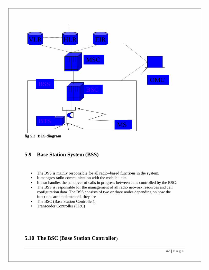
fig 5.2 :BTS diagram
5.9 Base Station System (BSS)
• The BSS is mainly responsible for all radio–based functions in the system.
• It manages radio communication with the mobile units.
• It also handles the handover of calls in progress between cells controlled by the BSC.
• The BSS is responsible for the management of all radio network resources and cell
configuration data. The BSS consists of two or three nodes depending on how the
functions are implemented, they are
• The BSC (Base Station Controller),
• Transcoder Controller (TRC)
5.10 The BSC (Base Station Controller)

43 | P a g e
The basic functional responsibilities assigned to the BSC are –
• Radio network management
• Radio network performance monitoring
• Operation, maintenance and administration of BTS
• Speech coding and rate adaptation
• Transmission management towards RBS
• Handling of the radio resources during mobile station connection
5.11 Transcoder Controller (TRC)
The primary functions of a TRC are to perform transcoding and to perform rate
adaptation.
• Transcoding: The function of converting from the PCM coder information (following
A/D conversion) to the GSM speech coder information is called transcoding. This
function is present in both the MS and BSS
.
Rate Adaptation: Rate adaptation involves the conversion of information arriving from the
MSC/VLR at a rate of 64 kb/s to a rate of 16 kb/s for transmission to a BSC (for Full Rate call).
This 16 kb/s contains 13 kb/s of traffic and 3 kb/s of in band signaling information
5.12 BSS
BSS is comprised of standard two or three types of nodes depending on the preferred
configuration. These are –
• Option-1: Combined BSC/TRC and
RBS
• Option-2: Stand Alone BSC,
Stand Alone TRC, and
RBS
5.13 Microwave link from one to another BTS tower

44 | P a g e
5.14 Important features
AC Power Distribution Cabinet
Battery
BTS Cabinet
Connecting Cable
Feeder Window
Grounding Bus Bar
Grounding Clips
Lighting Arrestor for Power Supply
Cable Rack
5.14.1 AC Power Distribution Cabinet
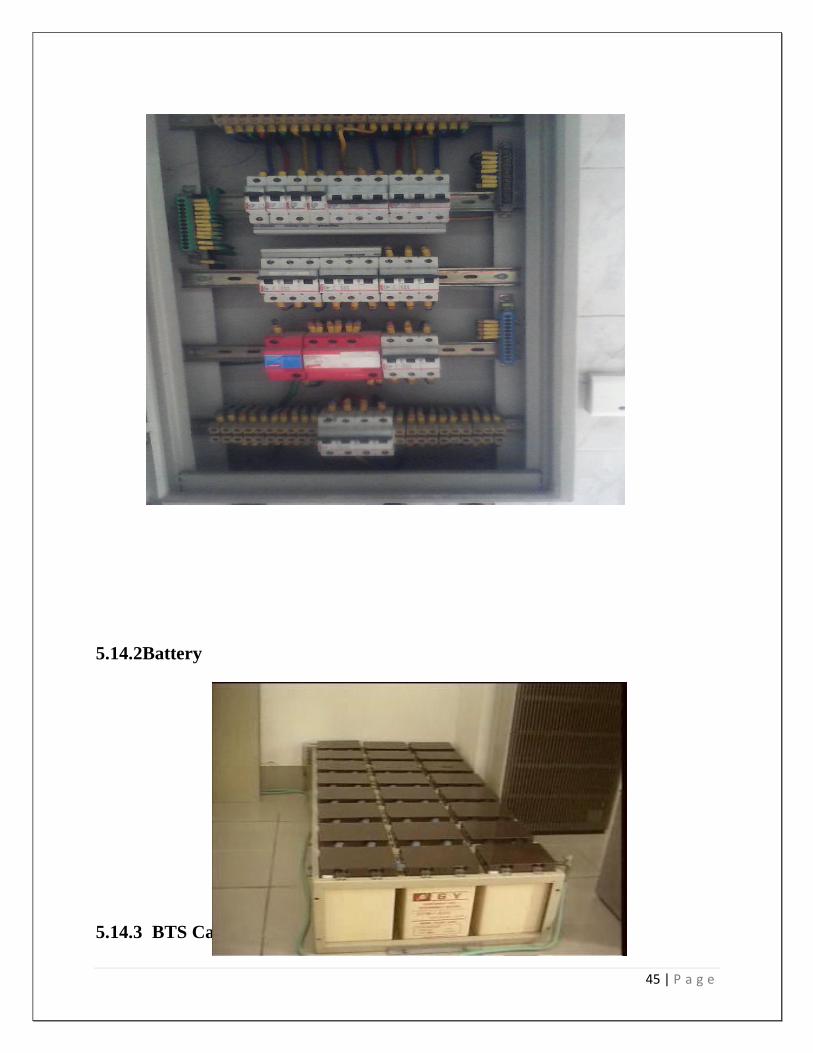
45 | P a g e
5.14.2Battery
5.14.3 BTS Cabinet
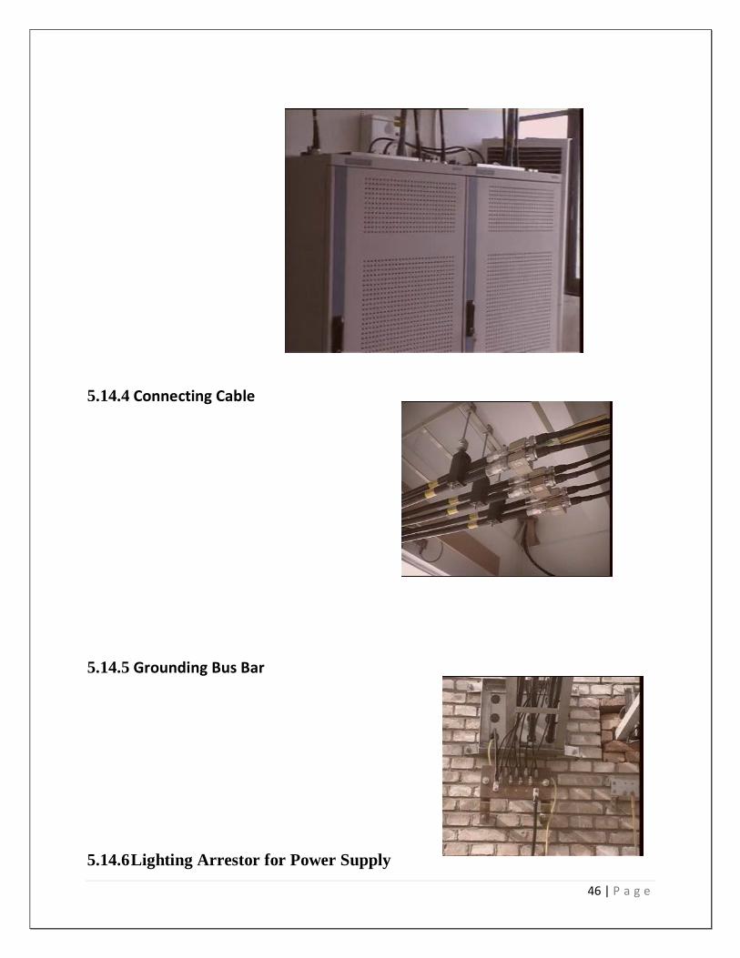
46 | P a g e
5.14.4 Connecting Cable
5.14.5 Grounding Bus Bar
5.14.6 Lighting Arrestor for Power Supply
47 | P a g e
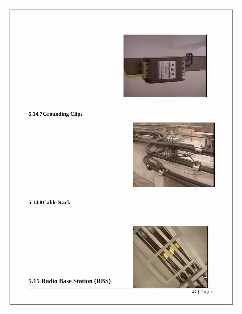
5.14.7 Grounding Clips
5.14.8 Cable Rack
5.15 Radio Base Station (RBS)
48 | P a g e
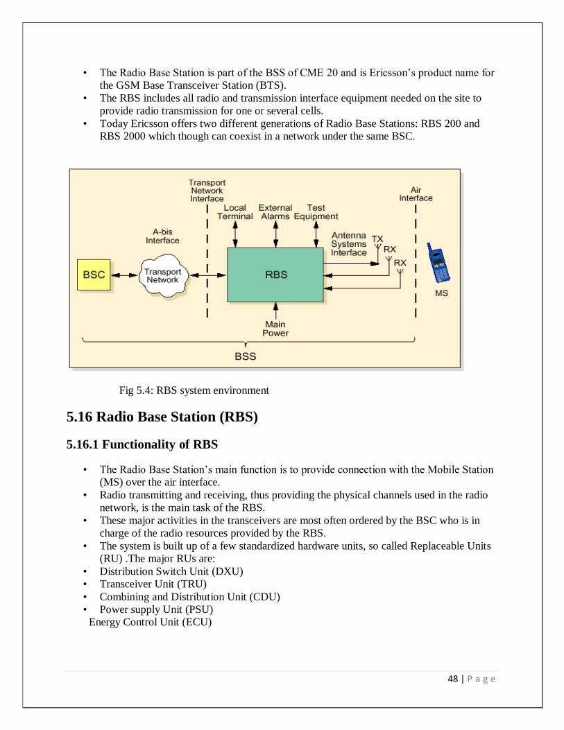
• The Radio Base Station is part of the BSS of CME 20 and is Ericsson‟s product name for
the GSM Base Transceiver Station (BTS).
• The RBS includes all radio and transmission interface equipment needed on the site to
provide radio transmission for one or several cells.
• Today Ericsson offers two different generations of Radio Base Stations: RBS 200 and
RBS 2000 which though can coexist in a network under the same BSC.
Fig 5.4: RBS system environment
5.16 Radio Base Station (RBS)
5.16.1 Functionality of RBS
• The Radio Base Station‟s main function is to provide connection with the Mobile Station
(MS) over the air interface.
• Radio transmitting and receiving, thus providing the physical channels used in the radio
network, is the main task of the RBS.
• These major activities in the transceivers are most often ordered by the BSC who is in
charge of the radio resources provided by the RBS.
• The system is built up of a few standardized hardware units, so called Replaceable Units
(RU) .The major RUs are:
• Distribution Switch Unit (DXU)
• Transceiver Unit (TRU)
• Combining and Distribution Unit (CDU)
• Power supply Unit (PSU)
Energy Control Unit (ECU)

49 | P a g e
5.17 BSS Interfaces
There are four primary interfaces within the BSS where traffic and signaling information is
received and transmitted. These interfaces are:
• A Interface.
• A-ter Interface (Ericsson Proprietary)
• A-bis Interface, and
• Air or Um Interface.
• The A interface exchanges information between the MSC/VLR and the TRC.
• The A-ter interface between the BSC and TRC.
• The A-bis interface transmits information between BSC and BTS, and
• The Air or Um interface operates between BTS and MS.
5.18 PDS: Plesiochronous Digital Hierarchy.
5.19 SDH: Synchronous Digital Hierarchy.
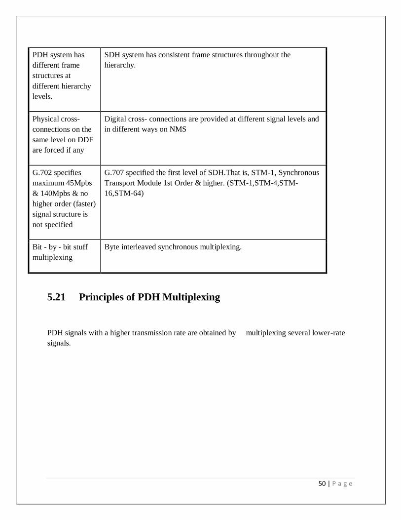
5.20 Comparison of SDH/PDH:
PDH SDH
The reference clock
is not synchronized
throughout the
network
The reference clock is synchronized throughout the network.
Multiplexing /
Demultiplexing
operations have to
be performed from
one level to the next
level step by step.
The synchronous multiplexing results in simple access to SDH
system has consistent frame structures throughout the hierarchy.
50 | P a g e
PDH system has
different frame
structures at
different hierarchy
levels.
SDH system has consistent frame structures throughout the
hierarchy.
Physical cross-
connections on the
same level on DDF
are forced if any
Digital cross- connections are provided at different signal levels and
in different ways on NMS
G.702 specifies
maximum 45Mpbs
& 140Mpbs & no
higher order (faster)
signal structure is
not specified
G.707 specified the first level of SDH.That is, STM-1, Synchronous
Transport Module 1st Order & higher. (STM-1,STM-4,STM-
16,STM-64)
Bit - by - bit stuff
multiplexing
Byte interleaved synchronous multiplexing.
5.21 Principles of PDH Multiplexing
PDH signals with a higher transmission rate are obtained by multiplexing several lower-rate
signals.
51 | P a g e
CHAPTER-06
AC Power and Alarming System
6.1 Introduction
52 | P a g e
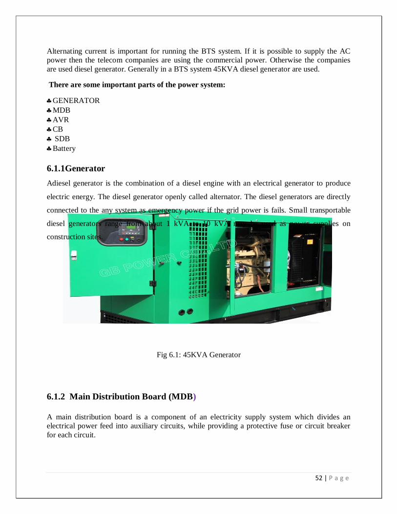
Alternating current is important for running the BTS system. If it is possible to supply the AC
power then the telecom companies are using the commercial power. Otherwise the companies
are used diesel generator. Generally in a BTS system 45KVA diesel generator are used.
There are some important parts of the power system:
GENERATOR
MDB
AVR
CB
SDB
Battery
6.1.1Generator
Adiesel generator is the combination of a diesel engine with an electrical generator to produce
electric energy. The diesel generator openly called alternator. The diesel generators are directly
connected to the any system as emergency power if the grid power is fails. Small transportable
diesel generators range from about 1 kVA to 10 kVA may be used as power supplies on
construction sites.
Fig 6.1: 45KVA Generator
6.1.2 Main Distribution Board (MDB)
A main distribution board is a component of an electricity supply system which divides an
electrical power feed into auxiliary circuits, while providing a protective fuse or circuit breaker
for each circuit.

53 | P a g e
Normally, a main switch, and in recent boards, one or more Residual-current devices (RCD) or
Residual Current Breakers with Over current protection (RCBO), will also be incorporated.
Fig 6.2: Main Distribution Board in BTS room.
6.1.3 AVR (Automatic Voltage Regulator)
A voltage regulator is an electricalregulator designed to automatically maintain a constant
voltage level. A voltage regulator is an example of a negativefeedbackcontrolloop. It may use an
electromechanical mechanism, or electronic components. Depending on the design, it may be
used to regulate one or more AC or DC voltages.
Electronic voltage regulators are found in devices such as computer powersupplies where they
stabilize the DC voltages used by the processor and other elements. In automobile alternators and
central powerstation generator plants, voltage regulators control the output of the plant. In an
electricpowerdistribution system, voltage regulators may be installed at a substation or along
distribution lines so that all customers receive steady voltage independent of how much power is
drawn from the line. With the exception of passive shunt regulators, all modern electronic
voltage regulators operate by comparing the actual output voltage to some internal fixed
reference voltage. Any difference is amplified and used to control the regulation element in such
a way as to reduce the voltage error. This forms a negative feedback control loop; increasing the
open-loop gain tends to increase regulation accuracy but reduce stability (avoidance of
oscillation, or ringing during step changes).
54 | P a g e
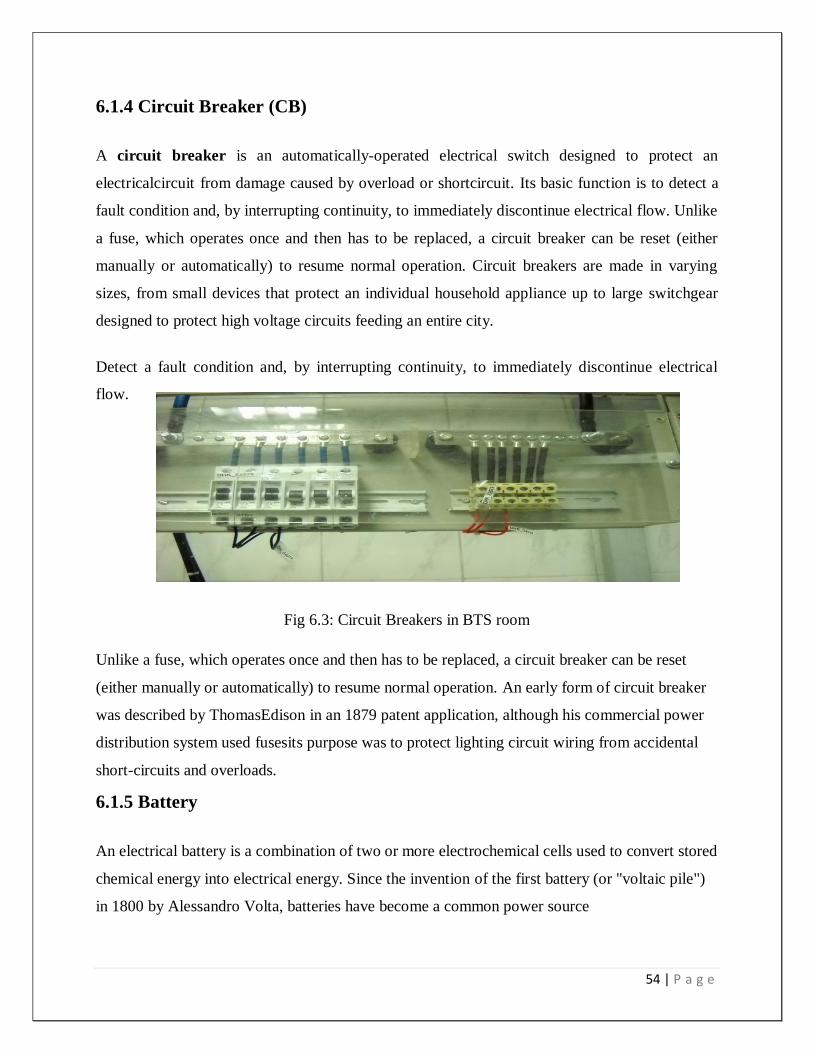
6.1.4 Circuit Breaker (CB)
A circuit breaker is an automatically-operated electrical switch designed to protect an
electricalcircuit from damage caused by overload or shortcircuit. Its basic function is to detect a
fault condition and, by interrupting continuity, to immediately discontinue electrical flow. Unlike
a fuse, which operates once and then has to be replaced, a circuit breaker can be reset (either
manually or automatically) to resume normal operation. Circuit breakers are made in varying
sizes, from small devices that protect an individual household appliance up to large switchgear
designed to protect high voltage circuits feeding an entire city.
Detect a fault condition and, by interrupting continuity, to immediately discontinue electrical
flow.
Fig 6.3: Circuit Breakers in BTS room
Unlike a fuse, which operates once and then has to be replaced, a circuit breaker can be reset
(either manually or automatically) to resume normal operation. An early form of circuit breaker
was described by ThomasEdison in an 1879 patent application, although his commercial power
distribution system used fusesits purpose was to protect lighting circuit wiring from accidental
short-circuits and overloads.
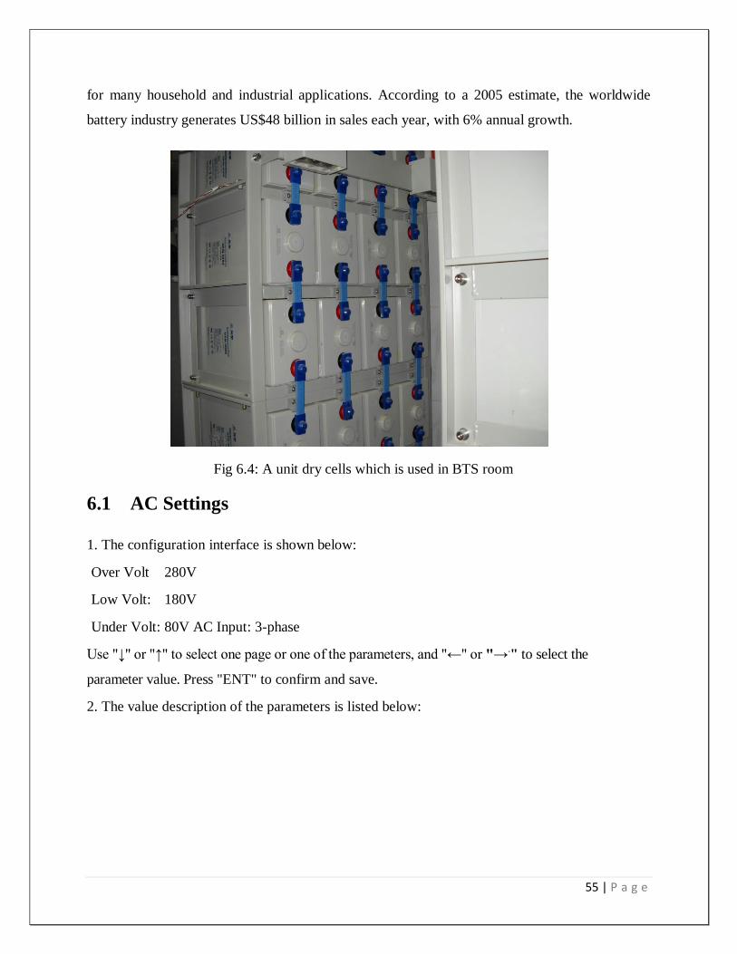
6.1.5 Battery
An electrical battery is a combination of two or more electrochemical cells used to convert stored
chemical energy into electrical energy. Since the invention of the first battery (or "voltaic pile")
in 1800 by Alessandro Volta, batteries have become a common power source
55 | P a g e
for many household and industrial applications. According to a 2005 estimate, the worldwide
battery industry generates US$48 billion in sales each year, with 6% annual growth.
Fig 6.4: A unit dry cells which is used in BTS room
6.1 AC Settings
1. The configuration interface is shown below:
Over Volt 280V
Low Volt: 180V
Under Volt: 80V AC Input: 3-phase
Use "↓" or "↑" to select one page or one of the parameters, and "←" or "→." to select the
parameter value. Press "ENT" to confirm and save.
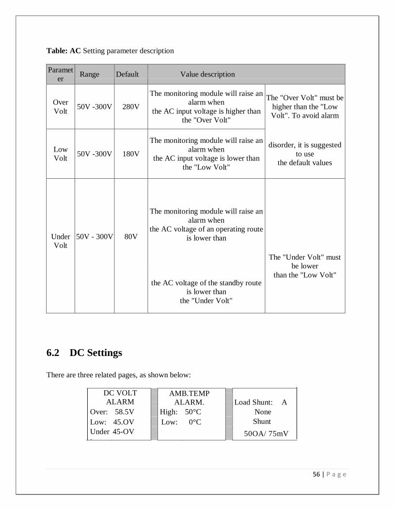
2. The value description of the parameters is listed below:
56 | P a g e
Table: AC Setting parameter description
Paramet
er Range Default Value description
Over
Volt 50V -300V 280V
The monitoring module will raise an
alarm when
the AC input voltage is higher than
the "Over Volt"
The "Over Volt" must be
higher than the "Low
Volt". To avoid alarm
Low
Volt 50V -300V 180V
The monitoring module will raise an
alarm when
the AC input voltage is lower than
the "Low Volt"
disorder, it is suggested
to use
the default values
Under
Volt
50V - 300V
80V
The monitoring module will raise an
alarm when
the AC voltage of an operating route
is lower than
The "Under Volt" must
be lower
the AC voltage of the standby route
is lower than
the "Under Volt"
than the "Low Volt"
6.2 DC Settings
There are three related pages, as shown below:
DC VOLT
ALARM
AMB.TEMP
ALARM.
Load Shunt: A
Over: 58.5V High: 50°C None
Low: 45.OV Low: 0°C Shunt
Coeff: Under
:
45-OV 50OA/ 75mV
57 | P a g e
Use "↑" or "↑" to select one page or one of the parameters, and " t " or to select the
parameter value. Press "ENT" to confirm and save.
6.3 Rectifier Setting
1. There are three related pages, as shown below:
Use "↓" or "↑" to select one page or one of the parameters, and "←" or →" to select the
parameter value. Press "ENT" to confirm and save.
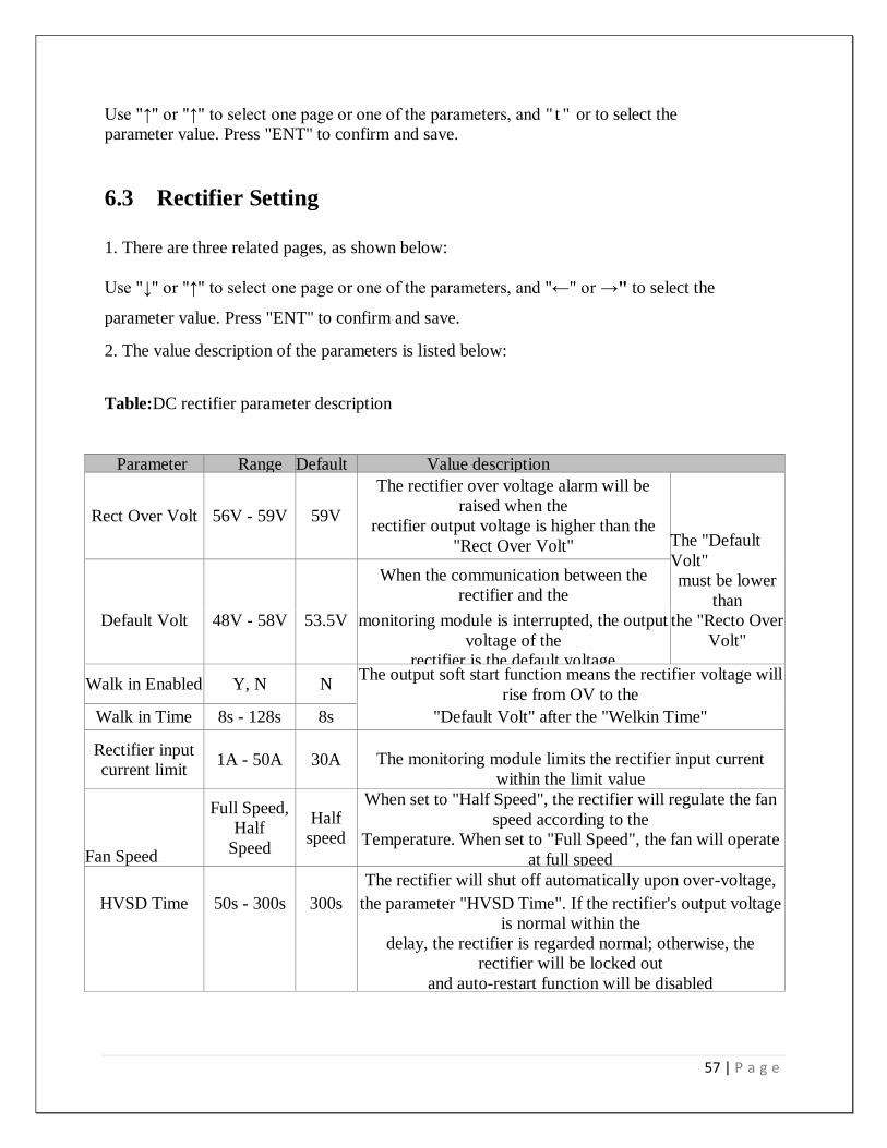
2. The value description of the parameters is listed below:
Table:DC rectifier parameter description
Parameter Range Default Value description
Rect Over Volt 56V - 59V 59V
The rectifier over voltage alarm will be
raised when the
rectifier output voltage is higher than the
"Rect Over Volt" The "Default
Volt"
must be lower
than
When the communication between the
rectifier and the
Default Volt 48V - 58V 53.5V monitoring module is interrupted, the output
voltage of the
rectifier is the default voltage
the "Recto Over
Volt"
Walk in Enabled Y, N N The output soft start function means the rectifier voltage will
rise from OV to the
Walk in Time 8s - 128s 8s "Default Volt" after the "Welkin Time"
Rectifier input
current limit 1A - 50A 30A The monitoring module limits the rectifier input current
within the limit value
Fan Speed
Full Speed,
Half
Speed
Half
speed
When set to "Half Speed", the rectifier will regulate the fan
speed according to the
Temperature. When set to "Full Speed", the fan will operate
at full speed
The rectifier will shut off automatically upon over-voltage,
HVSD Time 50s - 300s 300s the parameter "HVSD Time". If the rectifier's output voltage
is normal within the
delay, the rectifier is regarded normal; otherwise, the
rectifier will be locked out
and auto-restart function will be disabled
58 | P a g e
6.4 Electrical Installation
6.5.1 Connecting Power Cables
6.5.2 Danger:
Switch off all MCBs and pull out all fuses before the electrical connection.
Only the qualified personnel can do the mains cable connection.
6.5.3 Connecting grounding cable Connect one end of the grounding cable to the grounding bus bar of the machine room, and
the other end to thegrounding bus bar of the system.
6.5.4 Connecting AC cables
Take PS48300/1800-X1 system for example. Feed the AC cables into the cabinet from the top.
Connect them to theinput MCB.
6.5.5 Connection of load cables Connect the negative cable of the load to the upper terminal of "negative DC output MCB". Connect the positive cableof the load to the "positive DC output bus bar", as shown in Figure the batteries may have dangerous current. Before connecting the battery cables, the corresponding battery input muss or the battery cell connector must be disconnected to avoid live state of the power system after installation. 6.5.6 Connecting Signal Cables All the signal cables are connected to the signal transfer board. The position of the signal transfer board is shown in The temperature sensor (cable) is an optional accessory.
Operating voltage: 5V
Measurement range: -5°C - 100°C
Measurement precision: ± 2°C
Installation procedures:
Connect the 3-core plug of the temperature sensor cable to the J10 or J11 socket on board Put the temperature probe in the battery room where best represents the ambient temperature of the battery. Do not connect it to other heat-generating equipment
6.5.7 Safety Regulation Certain components in this power system have hazardous voltage and current. Always follow the
instructions below:
1. Only the adequately trained personnel with satisfactory knowledge of the
power system can carry out the installation. The most recent revision of these
safety rules and local safety rules in force shall be adhered to during the
installation.
2. All external circuits that are below 48V and connected to the power
systemmust comply with the requirements of SELV as defined in IEC 60950
59 | P a g e
3. Make sure that the power (mains and battery) to the system is cut off before
any operations can be carried out within the system cabinet.
6.6. Alarming system
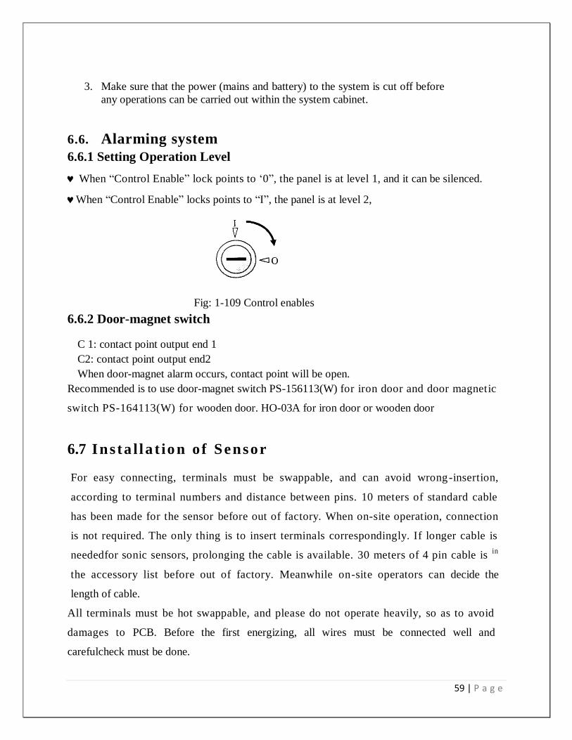
6.6.1 Setting Operation Level
When “Control Enable” lock points to „0”, the panel is at level 1, and it can be silenced.
When “Control Enable” locks points to “I”, the panel is at level 2,
Fig: 1-109 Control enables
6.6.2 Door-magnet switch
C 1: contact point output end 1
C2: contact point output end2
When door-magnet alarm occurs, contact point will be open.
Recommended is to use door-magnet switch PS-156113(W) for iron door and door magnetic
switch PS-164113(W) for wooden door. HO-03A for iron door or wooden door
6.7 Ins ta l l a t io n of Sensor
For easy connecting, terminals must be swappable, and can avoid wrong-insertion,
according to terminal numbers and distance between pins. 10 meters of standard cable
has been made for the sensor before out of factory. When on-site operation, connection
is not required. The only thing is to insert terminals correspondingly. If longer cable is
neededfor sonic sensors, prolonging the cable is available. 30 meters of 4 pin cable is in
the accessory list before out of factory. Meanwhile on-site operators can decide the
length of cable.
All terminals must be hot swappable, and please do not operate heavily, so as to avoid
damages to PCB. Before the first energizing, all wires must be connected well and
carefulcheck must be done.
60 | P a g e
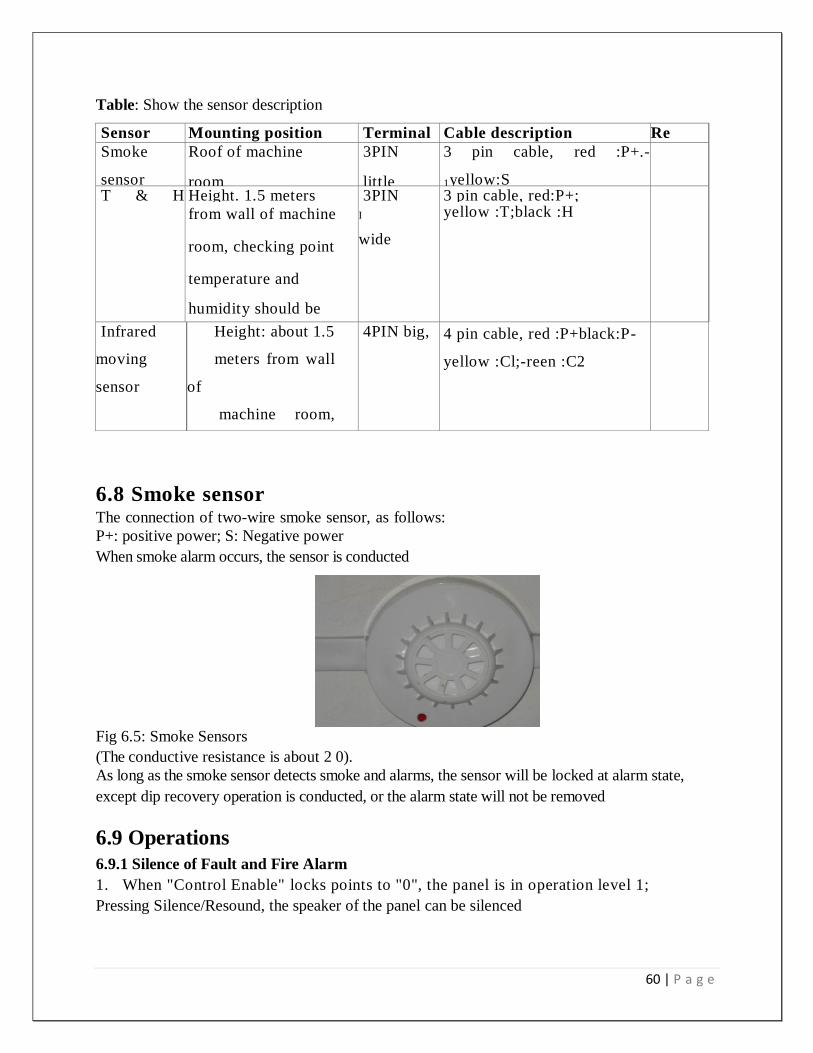
Table: Show the sensor description
Sensor Mounting position Terminal Cable description Re
m
ar
k
Smoke
sensor
Roof of machine
room
3PIN
little
3 pin cable, red :P+.-
1yellow:S
T & H
sensor
Height. 1.5 meters 3PIN 3 pin cable, red:P+;
from wall of machine
room, checking point
temperature and
humidity should be
Representative.
I
wide
yellow :T;black :H
Infrared
moving
sensor
Height: about 1.5
meters from wall
of
machine room,
can
detect the whole
Machine room.
4PIN big, 4 pin cable, red :P+black:P-
yellow :Cl;-reen :C2
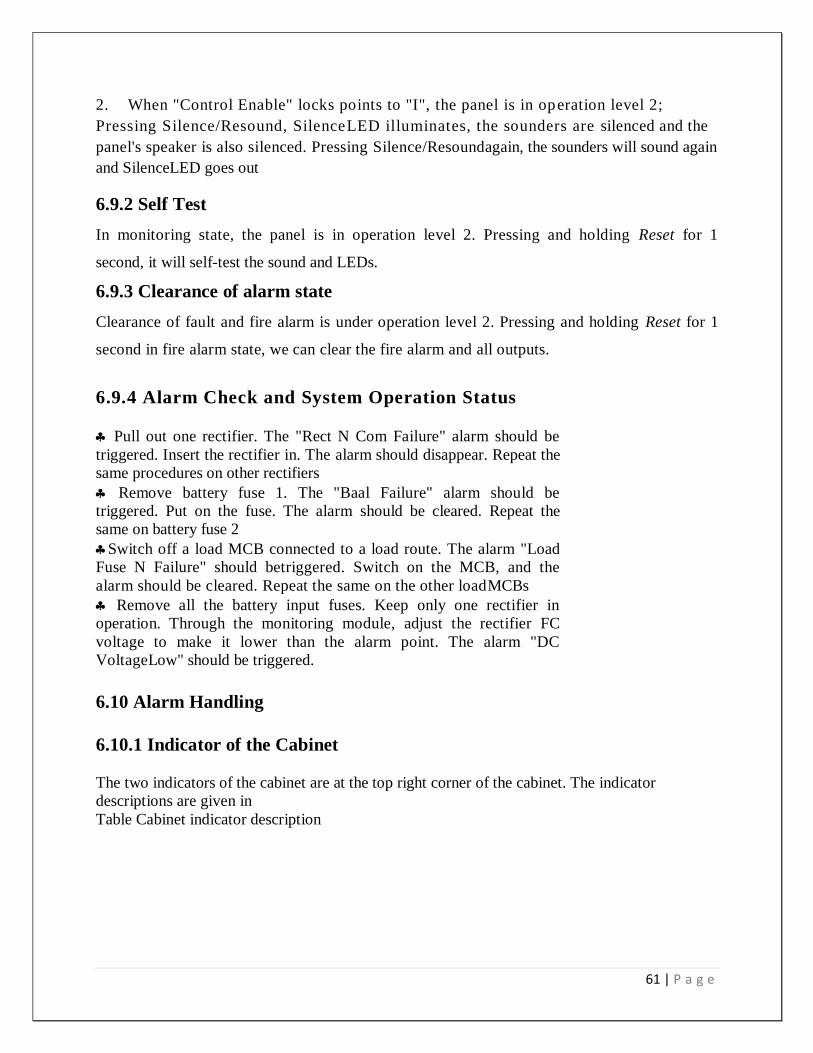
6.8 Smoke sensor The connection of two-wire smoke sensor, as follows:
P+: positive power; S: Negative power
When smoke alarm occurs, the sensor is conducted
Fig 6.5: Smoke Sensors
(The conductive resistance is about 2 0).
As long as the smoke sensor detects smoke and alarms, the sensor will be locked at alarm state,
except dip recovery operation is conducted, or the alarm state will not be removed
6.9 Operations
6.9.1 Silence of Fault and Fire Alarm
1. When "Control Enable" locks points to "0", the panel is in operation level 1;
Pressing Silence/Resound, the speaker of the panel can be silenced
61 | P a g e
2. When "Control Enable" locks points to "I", the panel is in operation level 2;
Pressing Silence/Resound, SilenceLED illuminates, the sounders are silenced and the
panel's speaker is also silenced. Pressing Silence/Resoundagain, the sounders will sound again
and SilenceLED goes out
6.9.2 Self Test
In monitoring state, the panel is in operation level 2. Pressing and holding Reset for 1
second, it will self-test the sound and LEDs.
6.9.3 Clearance of alarm state
Clearance of fault and fire alarm is under operation level 2. Pressing and holding Reset for 1
second in fire alarm state, we can clear the fire alarm and all outputs.
6.9.4 Alarm Check and System Operation Status
Pull out one rectifier. The "Rect N Com Failure" alarm should be
triggered. Insert the rectifier in. The alarm should disappear. Repeat the
same procedures on other rectifiers
Remove battery fuse 1. The "Baal Failure" alarm should be
triggered. Put on the fuse. The alarm should be cleared. Repeat the
same on battery fuse 2
Switch off a load MCB connected to a load route. The alarm "Load
Fuse N Failure" should betriggered. Switch on the MCB, and the
alarm should be cleared. Repeat the same on the other loadMCBs
Remove all the battery input fuses. Keep only one rectifier in
operation. Through the monitoring module, adjust the rectifier FC
voltage to make it lower than the alarm point. The alarm "DC
VoltageLow" should be triggered.
6.10 Alarm Handling
6.10.1 Indicator of the Cabinet
The two indicators of the cabinet are at the top right corner of the cabinet. The indicator
descriptions are given in
Table Cabinet indicator description

62 | P a g e
Indicator Normal
state Fault state Fault cause Handling method
Run
indicator
On Off No AC input Check if there is AC input voltage with a
multimeter Alarm
indicator Off On
System fault or
alarm
Check alarms generated by the
monitoring module,
6.10.2 Module Alarms
The monitoring module alarms are classified in four types: critical alarm, major alarm,
observation and no alarm.
Critical alarm, major alarm: these two types of alarms have strong impacts on the system
performance. Whenever these alarms are generated, users are supposed to handle them
immediately. The alarm indicators will be on and audible indication will be given.
Observation: when this type of alarm is raised, the system maintains normal output for a
while. If the alarm occurs during watch time, it should be handled immediately. If the alarm
occurs during non- watch- time, handle it during watch time. The alarm indicators will be on
when observation alarm occurs.
Table: System setting parameter description
No. Alarm Handling method
1 Mains Failure If the failure does not last long, the battery will power the load. If the cause is
unknown or the failure lasts too long, a diesel generator is needed. Before using
the generator's power, it is suggested to run the generator 5 minutes to stabilize
the power output
2 AC Voltage
High
Check if the AC Over-voltage point is too low. Reset the value if too low
A mild over-voltage does not affect the system operation. However, the rectifier
will stop operation when the mains voltage is more than 305V. Therefore, if the
power supply is constantly over-voltage, the mains
power network should be improved
3 AC Voltage
Low
Check if the AC Under- voltage point is too high. Reset the value if too high
When the mains voltage is lower than 176V, the output power of the rectifiers
will be Berated. If the power supply is constantly under-voltage, the main power
network should be improved

63 | P a g e
6.11 CONCLUSION
From our attachment program we have advanced knowledge on 3 Generation GSM technologies.
In Europe already 3.5 generation technology has been launched, in Bangladesh various mobile
operators are trying to launch 3.5G. We are very much indebted to grameenphone for this
attachment program. We wish more success of grameenphone ltd.
64 | P a g e
CHAPTER-07
References
65 | P a g e
www.grameenphone.com:
http://www.grameenphone.com
ARRL UHF/Microwave Experimenters Manual (American Radio Relay).
Freeman, R.L. Radio System Design for Telecommunication. 1987.
Hollemans , W., and A. Veschoor. Performance Study of Wave LAN and Arial Radio LANs:
Proceeding of the 5th IEEE Symposium on Personal, Indoor.
Lee, W.C.Y. Mobile Communication Design Fundamentals. 2nd
ed. Wiley and Sons, 1993.
Reudink, D. Advance Concept and Technologies for Communication Satellite: In Advance
Digital Communication. New York: Prentice Hall, 1987.