Embed Size (px)
Citation preview
Internship report OSLO AVANADE SERVICE ASSET
Date: 4 June 2009
Author: Rick Neeft
Intern assignment

TITELBLAD VAN HET STAGEVERSLAG
STAGEVERSLAG VOOR FONTYS HOGESCHOOL ICT TWEEDE STAGE
Gegevens student:
Naam + voorletters student: Neeft, Rick H.J.
Studentnummer: 2096303
Opleiding: Hogere Informatica
Stageperiode datum: van: 2 februari 2009 t/m 30 juni 2009
Gegevens bedrijf:
Naam bedrijf/instelling: Avanade Netherlands B.V.
Afdeling: Solution Developer
Plaats: Almere
Gegevens bedrijfsbegeleider:
Naam + voorletters: Loon, Gerben van
Functie: Solution Developer
Gegevens docentbegeleider:
Naam + voorletters: Broek, Peter P.C.M. van den
Gegevens verslag:
Titel stageverslag: Oslo Avanade Service Asset
Datum uitgifte stageverslag: 4 juni 2009
Getekend voor gezien door bedrijfsbegeleider:
Datum:
De bedrijfsbegeleider,

Internship report
Contents
Figures . . . . . . . . . . . . . . . . . . . . . . . . . . . . . . . . . . . viForeword . . . . . . . . . . . . . . . . . . . . . . . . . . . . . . . . . . viiiSamenvatting . . . . . . . . . . . . . . . . . . . . . . . . . . . . . . . . x
0 Introduction 1
1 Avanade 2
2 Technology and techniques 32.1 Service Oriented Architecture . . . . . . . . . . . . . . . . . . . . 32.2 Windows Communication Foundation . . . . . . . . . . . . . . . 3
2.2.1 What does WCF solve? . . . . . . . . . . . . . . . . . . . 42.2.2 The WCF solution . . . . . . . . . . . . . . . . . . . . . . 42.2.3 Technical implementation of WCF . . . . . . . . . . . . . 5
2.3 Domain Specific Language . . . . . . . . . . . . . . . . . . . . . . 52.4 ACA.NET . . . . . . . . . . . . . . . . . . . . . . . . . . . . . . . 62.5 Microsoft Oslo . . . . . . . . . . . . . . . . . . . . . . . . . . . . 72.6 Language M . . . . . . . . . . . . . . . . . . . . . . . . . . . . . . 7
2.6.1 MSchema . . . . . . . . . . . . . . . . . . . . . . . . . . . 82.6.2 MGraph . . . . . . . . . . . . . . . . . . . . . . . . . . . . 82.6.3 MGrammar . . . . . . . . . . . . . . . . . . . . . . . . . . 8
2.7 Runtime . . . . . . . . . . . . . . . . . . . . . . . . . . . . . . . . 10
3 The assignment 113.1 Background . . . . . . . . . . . . . . . . . . . . . . . . . . . . . . 113.2 Objective . . . . . . . . . . . . . . . . . . . . . . . . . . . . . . . 113.3 Approach . . . . . . . . . . . . . . . . . . . . . . . . . . . . . . . 11
4 Tooling 134.1 LATEX . . . . . . . . . . . . . . . . . . . . . . . . . . . . . . . . . 134.2 Intellipad . . . . . . . . . . . . . . . . . . . . . . . . . . . . . . . 14
5 The course of the project 155.1 Initialization phase . . . . . . . . . . . . . . . . . . . . . . . . . . 155.2 Learning phase . . . . . . . . . . . . . . . . . . . . . . . . . . . . 155.3 Research phase . . . . . . . . . . . . . . . . . . . . . . . . . . . . 155.4 Project ending phase . . . . . . . . . . . . . . . . . . . . . . . . . 16
ii

Internship report
6 Prototype OASA 186.1 Overview . . . . . . . . . . . . . . . . . . . . . . . . . . . . . . . 186.2 Requirements . . . . . . . . . . . . . . . . . . . . . . . . . . . . . 196.3 Oslo . . . . . . . . . . . . . . . . . . . . . . . . . . . . . . . . . . 19
6.3.1 Oasa Database (identities) . . . . . . . . . . . . . . . . . . 206.3.2 Language . . . . . . . . . . . . . . . . . . . . . . . . . . . 20
6.4 C# Runtime . . . . . . . . . . . . . . . . . . . . . . . . . . . . . 216.4.1 Runtime Program: Console Host . . . . . . . . . . . . . . 236.4.2 Sequence diagram . . . . . . . . . . . . . . . . . . . . . . 23
7 Problems and solutions 267.1 T4 templates and CodeDomProvider . . . . . . . . . . . . . . . . 26
8 Conclusion 278.1 The answer . . . . . . . . . . . . . . . . . . . . . . . . . . . . . . 278.2 Microsoft Oslo . . . . . . . . . . . . . . . . . . . . . . . . . . . . 27
8.2.1 Positive points . . . . . . . . . . . . . . . . . . . . . . . . 278.2.2 Negative points . . . . . . . . . . . . . . . . . . . . . . . . 27
A Project Initiation Document 28A.1 Introduction . . . . . . . . . . . . . . . . . . . . . . . . . . . . . . 28
A.1.1 Purpose of this document . . . . . . . . . . . . . . . . . . 28A.2 Composition of the document . . . . . . . . . . . . . . . . . . . . 28A.3 Background . . . . . . . . . . . . . . . . . . . . . . . . . . . . . . 29
A.3.1 The Context of the project . . . . . . . . . . . . . . . . . 29A.4 Project Definition . . . . . . . . . . . . . . . . . . . . . . . . . . . 30
A.4.1 Project goals . . . . . . . . . . . . . . . . . . . . . . . . . 30A.4.2 Selected solution or approach . . . . . . . . . . . . . . . . 30A.4.3 Project scope . . . . . . . . . . . . . . . . . . . . . . . . . 30A.4.4 Products and/or outcome . . . . . . . . . . . . . . . . . . 30A.4.5 Exclusions . . . . . . . . . . . . . . . . . . . . . . . . . . . 30A.4.6 Dependencies . . . . . . . . . . . . . . . . . . . . . . . . . 30A.4.7 Preconditions . . . . . . . . . . . . . . . . . . . . . . . . . 31A.4.8 Assumptions . . . . . . . . . . . . . . . . . . . . . . . . . 31
A.5 Project Organisation Structure . . . . . . . . . . . . . . . . . . . 32A.5.1 Intern . . . . . . . . . . . . . . . . . . . . . . . . . . . . . 32A.5.2 Internship office . . . . . . . . . . . . . . . . . . . . . . . 32A.5.3 Intern supervisor . . . . . . . . . . . . . . . . . . . . . . . 33A.5.4 Intern Support (A) . . . . . . . . . . . . . . . . . . . . . . 33A.5.5 Intern Support (F) . . . . . . . . . . . . . . . . . . . . . . 34
A.6 Project Controls . . . . . . . . . . . . . . . . . . . . . . . . . . . 35A.6.1 Information management matrix . . . . . . . . . . . . . . 35A.6.2 Progress Checks . . . . . . . . . . . . . . . . . . . . . . . 35A.6.3 Issue management . . . . . . . . . . . . . . . . . . . . . . 35
A.7 Communication plan . . . . . . . . . . . . . . . . . . . . . . . . . 37A.7.1 Interested people . . . . . . . . . . . . . . . . . . . . . . . 37A.7.2 Communication channels . . . . . . . . . . . . . . . . . . 37
A.8 Initial Project Plan . . . . . . . . . . . . . . . . . . . . . . . . . . 38A.8.1 Project setup . . . . . . . . . . . . . . . . . . . . . . . . . 38A.8.2 Project timeline . . . . . . . . . . . . . . . . . . . . . . . 38
CONTENTS iii

Internship report
A.9 Business Case . . . . . . . . . . . . . . . . . . . . . . . . . . . . . 40A.9.1 Introduction . . . . . . . . . . . . . . . . . . . . . . . . . 40A.9.2 Reason . . . . . . . . . . . . . . . . . . . . . . . . . . . . 40A.9.3 Benefits . . . . . . . . . . . . . . . . . . . . . . . . . . . . 40A.9.4 Risks . . . . . . . . . . . . . . . . . . . . . . . . . . . . . . 40
Glossary . . . . . . . . . . . . . . . . . . . . . . . . . . . . . . . . . . . 41Bibliography . . . . . . . . . . . . . . . . . . . . . . . . . . . . . . . . . 42
iv CONTENTS

Internship report
List of Figures
2.1 SOA schematic view . . . . . . . . . . . . . . . . . . . . . . . . . 32.2 Systems in old days . . . . . . . . . . . . . . . . . . . . . . . . . 42.3 New central system . . . . . . . . . . . . . . . . . . . . . . . . . . 42.4 Request-Reply . . . . . . . . . . . . . . . . . . . . . . . . . . . . 52.5 Visual form designer of Visual Studio is a kind of DSL . . . . . . 62.6 The toolbox from ACA.NET . . . . . . . . . . . . . . . . . . . . 62.7 The visual tool: Quadrant . . . . . . . . . . . . . . . . . . . . . . 72.8 logo . . . . . . . . . . . . . . . . . . . . . . . . . . . . . . . . . . 82.9 Runtime program for Oslo input . . . . . . . . . . . . . . . . . . 10
3.1 Gantt Chart . . . . . . . . . . . . . . . . . . . . . . . . . . . . . . 11
4.1 Intellipad . . . . . . . . . . . . . . . . . . . . . . . . . . . . . . . 144.2 Intellipad with Hello World example . . . . . . . . . . . . . . . . 14
5.1 Overall timeline in this internship . . . . . . . . . . . . . . . . . . 17
6.1 Layering . . . . . . . . . . . . . . . . . . . . . . . . . . . . . . . . 186.2 Flow from input to database . . . . . . . . . . . . . . . . . . . . 196.3 ERD of the Oasa database . . . . . . . . . . . . . . . . . . . . . . 206.4 Classes of the Core . . . . . . . . . . . . . . . . . . . . . . . . . . 216.5 Screenshot from about the Console Host runtime program . . . . 236.6 UML 2.1 Sequence Diagram: Oasa Core . . . . . . . . . . . . . . 246.7 UML 2.1 Sequence Diagram: WcfCodeGenerator . . . . . . . . . 25
vi


Internship report
Foreword
In front of you, you find this report which describes my first internship atAvanade Netherlands where I did research on the new model driven platformfrom Microsoft, codenamed Oslo. I found this company through the Dutchmagazine: .NET managzine. After the first meeting with Edwin Jongsma, ca-pability director, I certainly knew I wanted this internship. Not only because Ihad a great first impression, but because I wanted an internship with MicrosoftTechnology.
This report describes the things I’ve learned over the weeks. Not only haveI learned a lot about the Microsoft technology, this whole report was a biglearning experience. I did this entire report in English because I wanted to testand improve my English.
Finally, I would like to thank the following people who have helped me dur-ing my internship: at first Edwin Jongsma and Avanade for giving me thisgreat opportunity and great experience, Gerben van Loon and Felienne Her-mans for their great support, Peter van den Broek for his support from Fontys,Bryan Sumter and Michael Wolbert for their help on some Oslo questions thatI had and last but certainly not least Sebastian van den Putten who helped mewith correcting, reading, correcting and reading of my English sentences.
Happy reading!
Rick Neeft,June 2009
viii
Internship report
Summary
At the Proffesional Developers Conference in October 2008, Microsoft launcheda new model driven platform codenamed Oslo. With this new platform it is pos-sible to create data through models and domain specific languages. This datacan then be executed at runtime with a program, like a web browser (a program)does with HTML pages (the data).
The modeling language M, a part of Oslo, has been examined as part of thisinternship. The prototype OASA used the given data from Oslo to create andexecute WCF services.
Avanade has, in its existence, built a software factory to create WCF services.During this internship an attempt was made to rebuild this technology on avery small base. By doing this, a picture has been formed about what Avanadecan do with the Oslo-technology in its solutions.
This report describes:
• the uses methods and technologies
• the course of this internship
• OASA
• issues
• conclusion
ix
Internship report
Samenvatting
Op de Proffesional Developers Conference in oktober van 2008 werd door Mi-crosoft een nieuw model gedreven platform gelanceerd, genaamd Oslo. Met ditplatform zou het mogelijk moeten zijn om met modellen en domein specifieketalen data te creren die een programma op runtime, interpreteert en uitvoert,zoals een HTML pagina (de data) en een browser (programma).
Voor deze stage is een onderdeel van Oslo, de modeleer taal M, tegen het lichtgehouden. Het prototype OASA gebruikt de gegeven data vanuit Oslo om eenWCF service te maken en uitvoeren.
Avanade heeft in de loop van haar bestaan een software factory gebouw omWCF service te kunnen maken. Tijdens deze stage is getracht om dit op minus-cule wijze na te bouwen. Hierdoor is er een beeld ontstaat wat Avanade metOslo zou kunnen doen in de bestaande methodieken.
Dit verslag beschrijft:
• de gebruikte methodieken en technologien
• het verloop van de stage
• beschrijving van OASA
• problemen
• conclusies
x
Internship report
0. Introduction
This report introduces you to the internship OASA. This assignment was carriedout as a bachelor internship within Avanade Netherlands. Avanade is a globalIT consultancy dedicated to using the Microsoft platform to help enterprisesachieve profitable growth.[1]
As technologies from Microsoft continue to evolve a, Avanade must evaluatehow to adept to the technologies. This internship has the purpose to find outwhat the new model driven platform, Oslo, can contribute to ACA.NET withthe focus on the M language.
This report is divided into several chapters:
• Chapter 1 Avanadethis chapter explains shortly who Avanade is and what they do.
• Chapter 2 Technology and techniquesthis chapter is dedicated to form a basic knowledge about the necessarytechnologies and methods
• Chapter 3 The assignmentthis chapter explains the assignment and its approach.
• Chapter 4 Toolingthis chapter explains the used tools and programs
• Chapter 5 The course of the projectthis chapter is about the process of this internship.
• Chapter 6 Prototype OASAthis chapter is dedicated to the prototype OASA.
• Chapter 7 Problems and solutionsthis chapter addresses some issues that came around.
• Chapter 8 Conclusionthis chapter captures the conclusion.
At the end of this report you find:
• Appendix A, Project Initiation Document
• Glossary
• Bibliograhy
1
Internship report
1. Avanade
In 2000, Microsoft and Accenture came together tocreate Avanade. A joint venture designed to meet thegrowing demand of Microsoft-based services amongenterprises worldwide. In the past 9 years, Avanade
has grown to become one of the largest Microsoft oriented companies in theworld. They have over 9000 employees of which 180 are working in the Nether-lands.
As seen in point 5 their core values1, Avanade demonstrate a Passion for Tech-nology. That is why their employers work with all kinds of technology, fromMicrosoft. But not only technology that ”works”. As the world of ICT evolvingevery day all kinds of new technologies are created.
The new model driven platform from Microsoft is one of those new technologiesthat Avanade is examine. To become and to stay the largest Microsoft orientedcompanies in the world, Avanade must exploring every new technology fromMicrosoft even when it is not finished.
1http://www.avanade.com/code/
2
Internship report
2. Technology and techniques
In this chapter the different technologies and techniques will be highlighted.This chapter will form the basic knowledge of what is necessarily for this in-ternship. It starts with the explanation of what a SOA is and how SOA’s areimplemented with WCF. After that what a DSL is and how ACA.NET usesDSLs to create (WCF) service application. Than Oslo, the M language and atthe end runtime.
2.1 Service Oriented Architecture
Today many programs are no longer stand alone applications, they share re-sources and data. Thanks to the internet many web applications have been built.
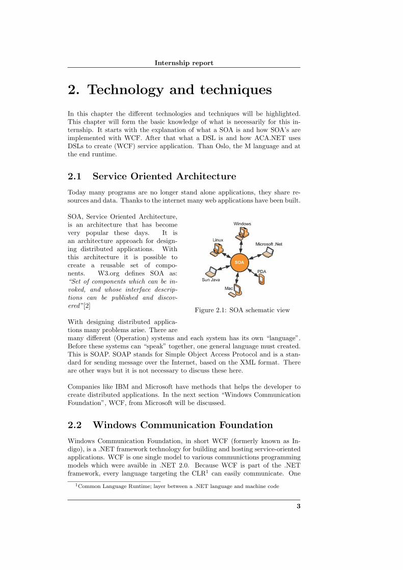
Figure 2.1: SOA schematic view
SOA, Service Oriented Architecture,is an architecture that has becomevery popular these days. It isan architecture approach for design-ing distributed applications. Withthis architecture it is possible tocreate a reusable set of compo-nents. W3.org defines SOA as:“Set of components which can be in-voked, and whose interface descrip-tions can be published and discov-ered”[2]
With designing distributed applica-tions many problems arise. There aremany different (Operation) systems and each system has its own “language”.Before these systems can “speak” together, one general language must created.This is SOAP. SOAP stands for Simple Object Access Protocol and is a stan-dard for sending message over the Internet, based on the XML format. Thereare other ways but it is not necessary to discuss these here.
Companies like IBM and Microsoft have methods that helps the developer tocreate distributed applications. In the next section “Windows CommunicationFoundation”, WCF, from Microsoft will be discussed.
2.2 Windows Communication Foundation
Windows Communication Foundation, in short WCF (formerly known as In-digo), is a .NET framework technology for building and hosting service-orientedapplications. WCF is one single model to various communictions programmingmodels which were avaible in .NET 2.0. Because WCF is part of the .NETframework, every language targeting the CLR1 can easily communicate. One
1Common Language Runtime; layer between a .NET language and machine code
3
Internship report
person creates a service with C# and an other programs the client with VisualBasic for example. Not only the .NET language can access the WCF service,other language, like Java, can do the same but then the functionality is limited.
2.2.1 What does WCF solve?
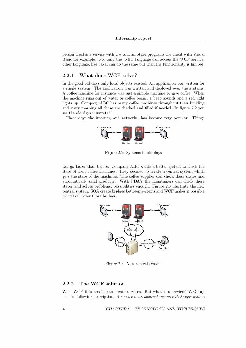
In the good old days only local objects existed. An application was written fora single system. The application was written and deployed over the systems.A coffee machine for instance was just a simple machine to give coffee. Whenthe machine runs out of water or coffee beans, a beep sounds and a red lightlights up. Company ABC has many coffee machines throughout their buildingand every morning all those are checked and filled if needed. In figure 2.2 yousee the old days illustrated.
These days the internet, and networks, has become very popular. Things
Figure 2.2: Systems in old days
can go faster than before. Company ABC wants a better system to check thestate of their coffee machines. They decided to create a central system whichgets the state of the machines. The coffee supplier can check these states andautomatically send products. With PDA’s the maintainers can check thesestates and solves problems, possibilities enough. Figure 2.3 illustrate the newcentral system. SOA create bridges between systems and WCF makes it possibleto “travel” over those bridges.
Figure 2.3: New central system
2.2.2 The WCF solution
With WCF it is possible to create services. But what is a service? W3C.orghas the following description: A service is an abstract resource that represents a
4 CHAPTER 2. TECHNOLOGY AND TECHNIQUES
Internship report
capability of performing tasks that form a coherent functionality from the pointof view of providers entities and requesters entities[3].
Another view upon a service is that it is a business-driven approach insteadof technical approach. A service should represent a function of a business. Forexample a service can be: make a shoe. The recourses (parameters) could be:leather and laces. Within the service, it can call components like: cut theleather.
2.2.3 Technical implementation of WCF
With WCF you can create contracts. A contract defines what the service cando and what it needs to do that. Example: The company ABC has a programthat writes a word backwards. Hello becomes olleH. The program also decideswhether it is a palindrome or not. The company is not satisfied with the appli-cation. When something needs to change, many computers must reinstall theapplication. After a talk with an IT company they decided to create a serviceand a client. When they need to change something they just update the serviceand the client would still run.
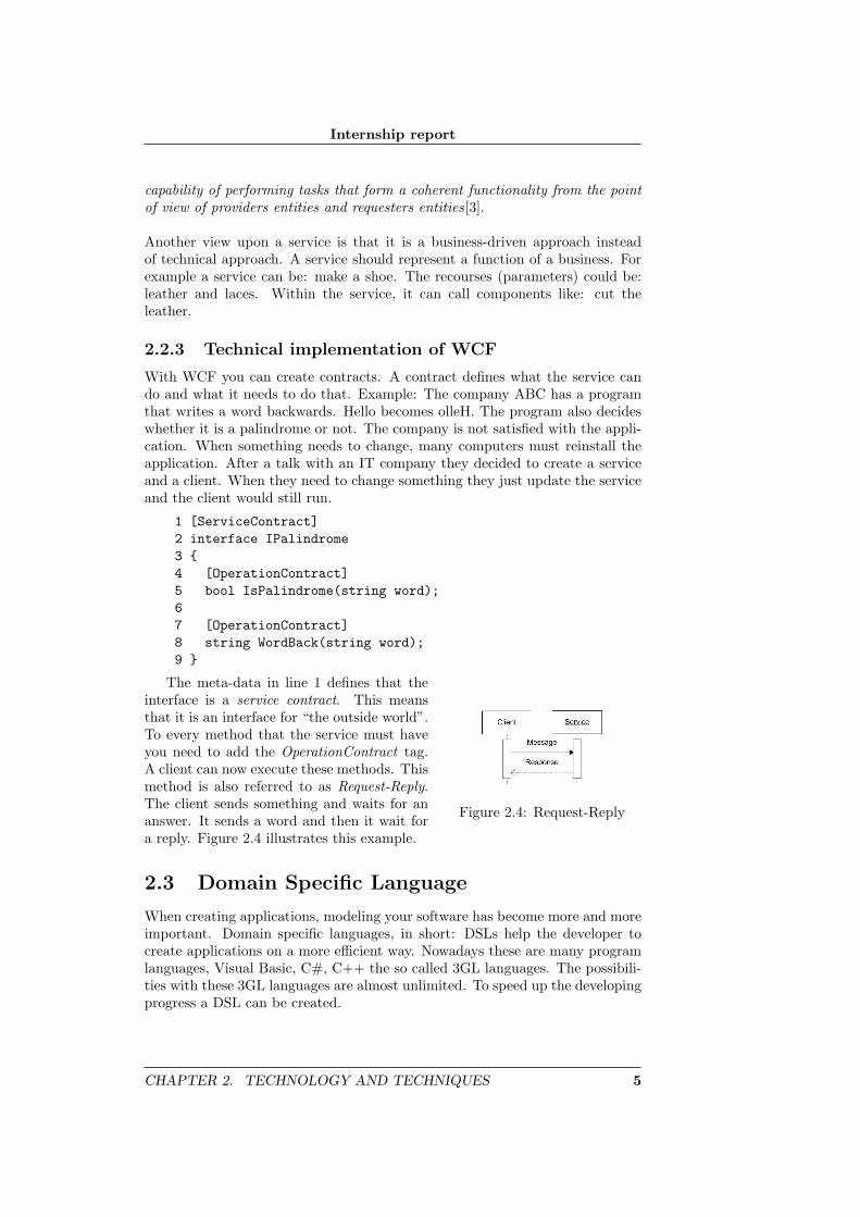
1 [ServiceContract]2 interface IPalindrome3 {4 [OperationContract]5 bool IsPalindrome(string word);67 [OperationContract]8 string WordBack(string word);9 }
Figure 2.4: Request-Reply
The meta-data in line 1 defines that theinterface is a service contract. This meansthat it is an interface for “the outside world”.To every method that the service must haveyou need to add the OperationContract tag.A client can now execute these methods. Thismethod is also referred to as Request-Reply.The client sends something and waits for ananswer. It sends a word and then it wait fora reply. Figure 2.4 illustrates this example.
2.3 Domain Specific Language
When creating applications, modeling your software has become more and moreimportant. Domain specific languages, in short: DSLs help the developer tocreate applications on a more efficient way. Nowadays these are many programlanguages, Visual Basic, C#, C++ the so called 3GL languages. The possibili-ties with these 3GL languages are almost unlimited. To speed up the developingprogress a DSL can be created.
CHAPTER 2. TECHNOLOGY AND TECHNIQUES 5
Internship report
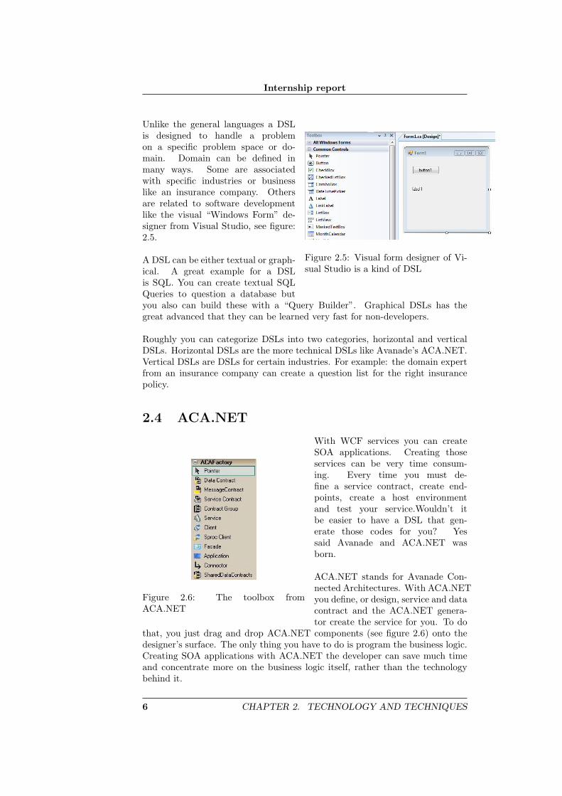
Figure 2.5: Visual form designer of Vi-sual Studio is a kind of DSL
Unlike the general languages a DSLis designed to handle a problemon a specific problem space or do-main. Domain can be defined inmany ways. Some are associatedwith specific industries or businesslike an insurance company. Othersare related to software developmentlike the visual “Windows Form” de-signer from Visual Studio, see figure:2.5.
A DSL can be either textual or graph-ical. A great example for a DSLis SQL. You can create textual SQLQueries to question a database butyou also can build these with a “Query Builder”. Graphical DSLs has thegreat advanced that they can be learned very fast for non-developers.
Roughly you can categorize DSLs into two categories, horizontal and verticalDSLs. Horizontal DSLs are the more technical DSLs like Avanade’s ACA.NET.Vertical DSLs are DSLs for certain industries. For example: the domain expertfrom an insurance company can create a question list for the right insurancepolicy.
2.4 ACA.NET
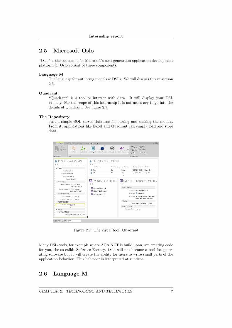
Figure 2.6: The toolbox fromACA.NET
With WCF services you can createSOA applications. Creating thoseservices can be very time consum-ing. Every time you must de-fine a service contract, create end-points, create a host environmentand test your service.Wouldn’t itbe easier to have a DSL that gen-erate those codes for you? Yessaid Avanade and ACA.NET wasborn.
ACA.NET stands for Avanade Con-nected Architectures. With ACA.NETyou define, or design, service and datacontract and the ACA.NET genera-tor create the service for you. To do
that, you just drag and drop ACA.NET components (see figure 2.6) onto thedesigner’s surface. The only thing you have to do is program the business logic.Creating SOA applications with ACA.NET the developer can save much timeand concentrate more on the business logic itself, rather than the technologybehind it.
6 CHAPTER 2. TECHNOLOGY AND TECHNIQUES
Internship report
2.5 Microsoft Oslo
“Oslo” is the codename for Microsoft’s next generation application developmentplatform.[4] Oslo consist of three components:
Language MThe language for authoring models & DSLs. We will discuss this in section2.6.
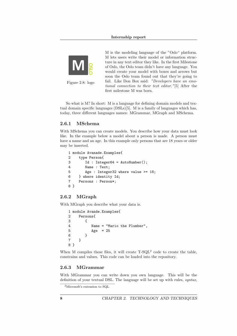
Quadrant“Quadrant” is a tool to interact with data. It will display your DSLvisually. For the scope of this internship it is not necessary to go into thedetails of Quadrant. See figure 2.7.
The RepositoryJust a simple SQL server database for storing and sharing the models.From it, applications like Excel and Quadrant can simply load and storedata.
Figure 2.7: The visual tool: Quadrant
Many DSL-tools, for example where ACA.NET is build upon, are creating codefor you, the so calld: Software Factory. Oslo will not become a tool for gener-ating software but it will create the ability for users to write small parts of theapplication behavior. This behavior is interpreted at runtime.
2.6 Language M
CHAPTER 2. TECHNOLOGY AND TECHNIQUES 7
Internship report
Figure 2.8: logo
M is the modeling language of the ”Oslo“ platform.M lets users write their model or information struc-ture in any text editor they like. In the first Milestoneof Oslo, the Oslo team didn’t have any language. Youwould create your model with boxes and arrows butsoon the Oslo team found out that they’re going tofail. Like Don Box said: ”Developers have an emo-tional connection to their text editor.”[5] After thefirst milestone M was born.
So what is M? In short: M is a language for defining domain models and tex-tual domain specific languages (DSLs)[5]. M is a family of languages which has,today, three different languages names: MGrammar, MGraph and MSchema.
2.6.1 MSchema
With MSchema you can create models. You describe how your data must looklike. In the example below a model about a person is made. A person musthave a name and an age. In this example only persons that are 18 years or oldermay be inserted.
1 module Avanade.Examples{2 type Person{3 Id : Integer64 = AutoNumber();4 Name : Text;5 Age : Integer32 where value >= 18;6 } where identity Id;7 Persons : Person*;8 }
2.6.2 MGraph
With MGraph you describe what your data is.
1 module Avande.Examples{2 Persons{3 {4 Name = "Mario the Plumber",5 Age = 256 }7 }8 }
When M compiles these files, it will create T-SQL2 code to create the table,constrains and values. This code can be loaded into the repository.
2.6.3 MGrammar
With MGrammar you can write down you own language. This will be thedefinition of your textual DSL. The language will be set up with rules, syntax,
2Microsoft’s extension to SQL
8 CHAPTER 2. TECHNOLOGY AND TECHNIQUES
Internship report
and words, tokens. Creating your language is actually set up a lot of regularexpression3 rules.
1 module Avande.Examples{2 language Persons{3 syntax Main = p:Person+4 => id("Persons"){valuesof(p)};5 syntax Person = "Person" "Name:" + n:Name + "Age:" + a:Age6 => {Name = n, Age = a};7 token Char = ’A’..’Z’ | ’a’..’z’;8 token Digit = ’0’..’9’;9 token Name = Char+;10 token Age = Digit+;11 interleave Whitespaces = ’ ’ | ’\r’ | ’\n’ | ’\t’;12 }13 }
Here below is described, in short, what each line does:
• As you can see in line 7 to 10, there are tokens defined. You can comparea token with a small unbreakable object, like letter of word (1 too manyletters).
• In line 3 and 5 you see syntaxes. A syntax is a line of the language. SyntaxPerson is build of the word Person followed by the word Name and a name.After that, the word Age followed with an age.
• In line 3 the syntax Main is defined. Syntax Main is a special syntax.Main is the syntax were M will start with parsing.
• In line 11 an interleave is defined. Interleaves are ignored by the M lan-guage. In this case the whitespace are ignored.
• In line 4 and 6 you can see those arrow sign. With that sign you specifyhow your graph must look like.
3A regular expression is a way to descript a patern that the computer can ”read”
CHAPTER 2. TECHNOLOGY AND TECHNIQUES 9
Internship report
2.7 Runtime
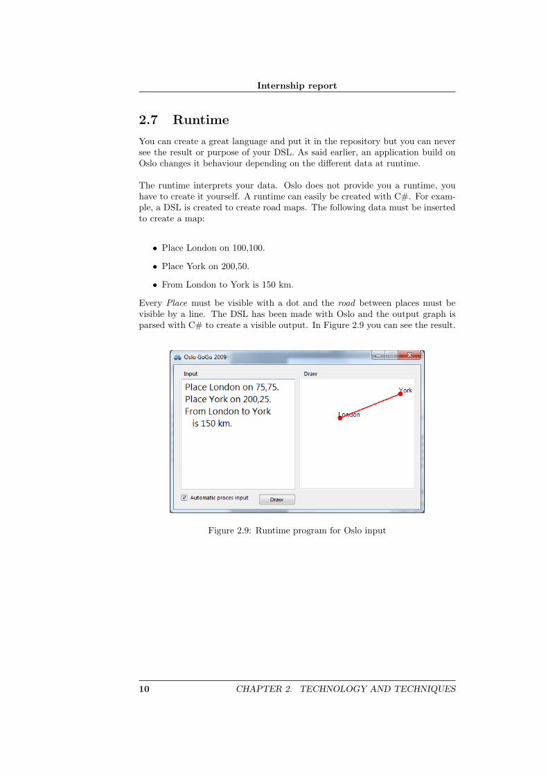
You can create a great language and put it in the repository but you can neversee the result or purpose of your DSL. As said earlier, an application build onOslo changes it behaviour depending on the different data at runtime.
The runtime interprets your data. Oslo does not provide you a runtime, youhave to create it yourself. A runtime can easily be created with C#. For exam-ple, a DSL is created to create road maps. The following data must be insertedto create a map:
• Place London on 100,100.
• Place York on 200,50.
• From London to York is 150 km.
Every Place must be visible with a dot and the road between places must bevisible by a line. The DSL has been made with Oslo and the output graph isparsed with C# to create a visible output. In Figure 2.9 you can see the result.
Figure 2.9: Runtime program for Oslo input
10 CHAPTER 2. TECHNOLOGY AND TECHNIQUES

Internship report
3. The assignment
3.1 Background
Creating WCF services with ACA.NET is very simple. Just drag and dropyour contract into a designer surface, program the business logic and let theACA.NET factory creates the code. This is a very fast way to program a SOAapplication. ACA.NET is build upon the DSL tools. These tools enable thedeveloper to create a DSL which creates WCF service very fast, of course, anyother domain specific language. Avanade believes that when Oslo is finished,Microsoft will stop developing and supporting the DSL tools. They want toknow how Oslo can support ACA.NET.
3.2 Objective
The objective of this research is contributing to the development of ACA.NETbyexamining how to start WCF services at runtime with Oslo.
3.3 Approach
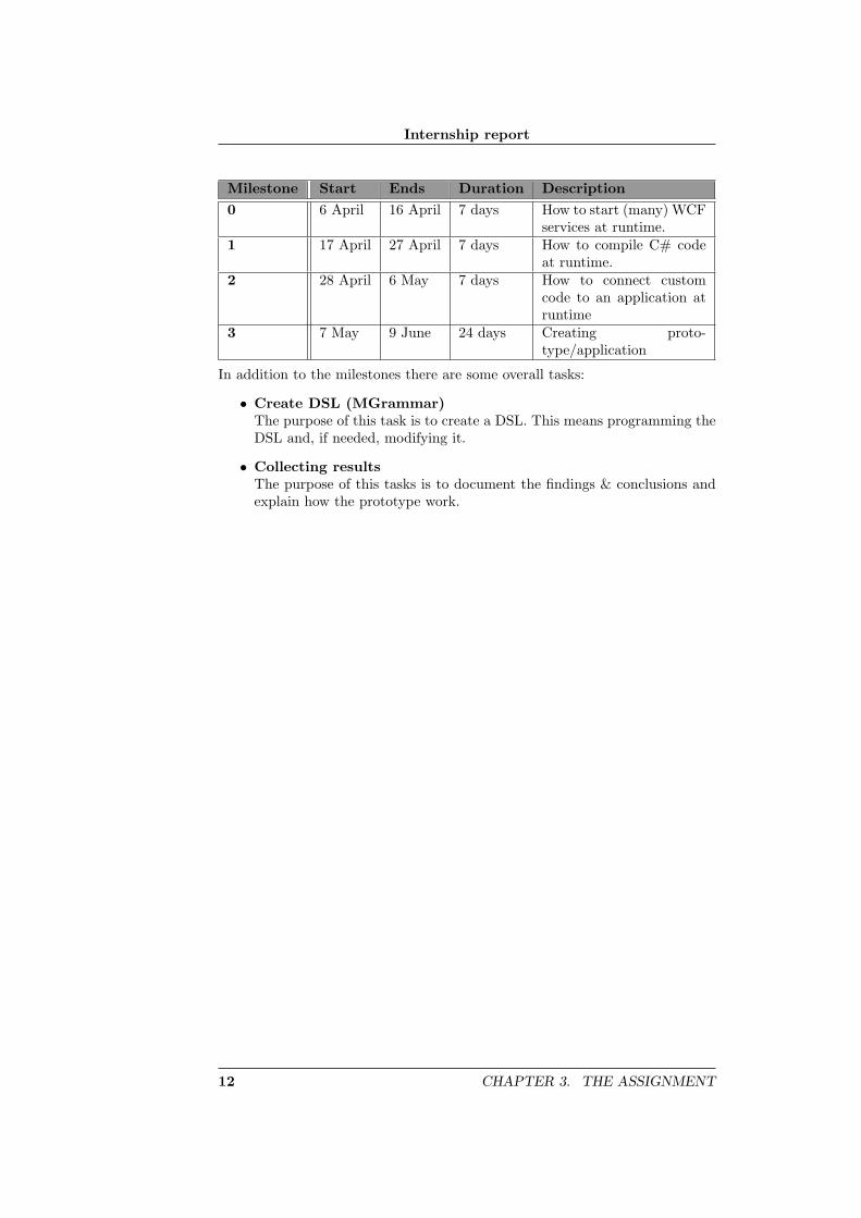
The assignment is divided into four milestones. A milestone marks the end of astage. Before a new milestone can begin the previous must be completed. Aftereach milestone the status of the project will be reviewed and the approach forthe next will be discussed. In this picture only the assignment part is shown.
Figure 3.1: Gantt Chart
11
Internship report
Milestone Start Ends Duration Description0 6 April 16 April 7 days How to start (many) WCF
services at runtime.1 17 April 27 April 7 days How to compile C# code
at runtime.2 28 April 6 May 7 days How to connect custom
code to an application atruntime
3 7 May 9 June 24 days Creating proto-type/application
In addition to the milestones there are some overall tasks:
• Create DSL (MGrammar)The purpose of this task is to create a DSL. This means programming theDSL and, if needed, modifying it.
• Collecting resultsThe purpose of this tasks is to document the findings & conclusions andexplain how the prototype work.
12 CHAPTER 3. THE ASSIGNMENT
Internship report
4. Tooling
In this chapter the tooling and programs for this internship are explained. Everytool or program will have a short explanation.
4.1 LATEX
Latex, pronounce as La-tech, is a macro package bases on TEXcreated by LeslieLamport in 1984. LaTeX document processing is essentially programming. Youcreate a text file in LaTeX markup. The LaTeX macro reads this to producethe final document.
It’s clearly that this has disadvantages in comparing to a WYSIWYG1 pro-gram. You have to program your document, than create the document (say:compile your file). Although the writer can’t see the result directly, it has itgreat advantaged:The writer is forced to concentrate on the text rather that itslayout. By doing that, LaTeX automates a lot, you don’t need to create yourown table of contents, take care of positing of titles, take care of word breaks etc.
Although you can create your document using Notepad or something like that,some programs helps you with creating LaTeX document. TeXnicCenter simpli-fies creating document by highlighting commands and a build-in compiler. Youcreate a document using TeXnicCenter and it will check for error’s and createa pdf document for you.
This report is created using LaTeX. Writing a document with Microsoft Wordcauses too many layout problems, especially when it’s created over a longer pe-riod. With LaTeX you just add or remove chapter and sections, LaTeX takescare of the rest.
1What You See Is What You Get
13
Internship report
4.2 Intellipad
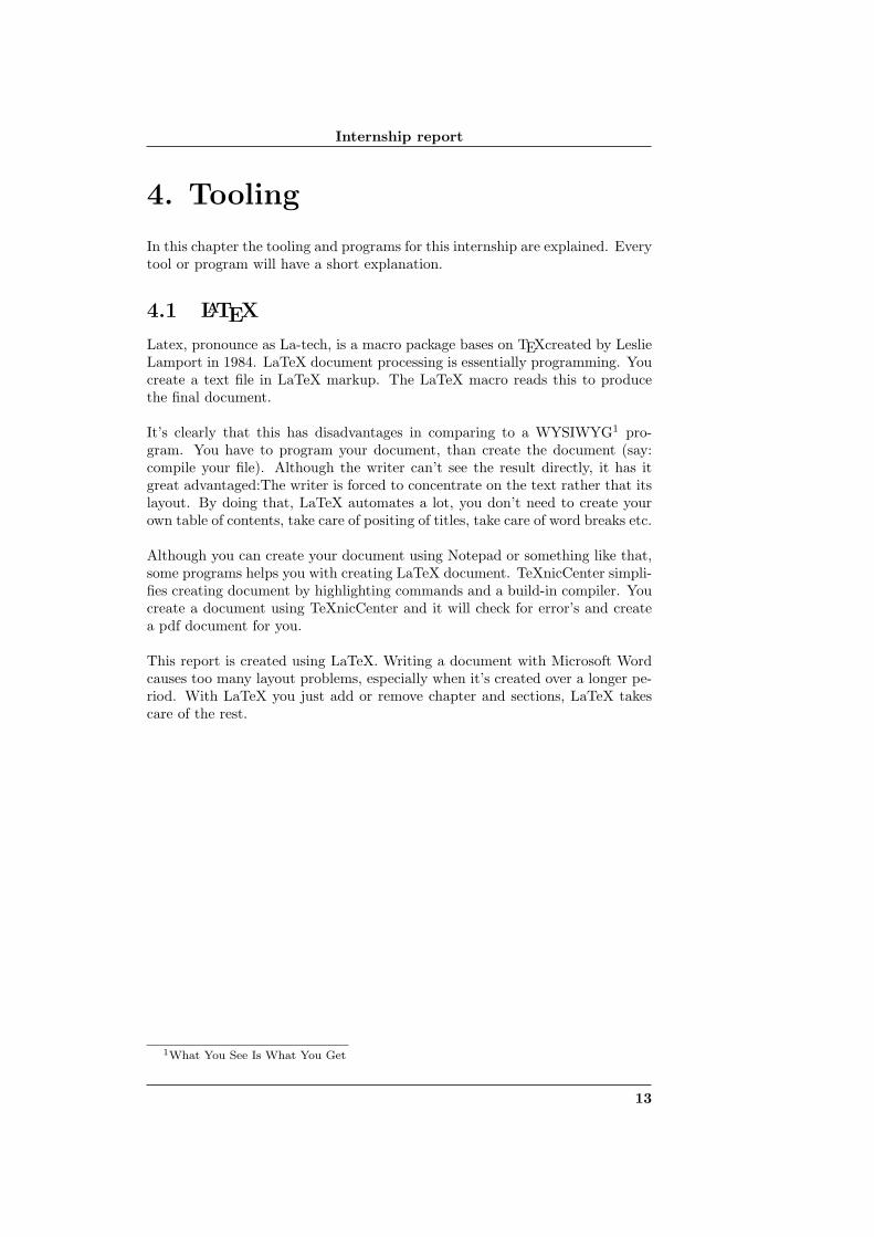
Intellipad is a light-weight text-editor for programming de “M” language. Itcan be seen as the a new advanced Notepad. In figure 4.1 Intellipad is shownin “Standard Mode”.
Figure 4.1: Intellipad
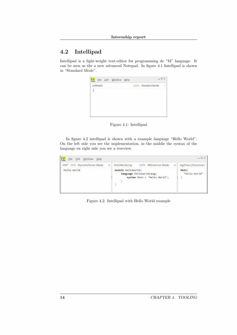
In figure 4.2 intellipad is shown with a example language “Hello World”.On the left side you see the implementation, in the middle the syntax of thelanguage en right side you see a treeview.
Figure 4.2: Intellipad with Hello World example
14 CHAPTER 4. TOOLING
Internship report
5. The course of the project
This chapter is about the process of this internship. The proposed plan will bediscussed and what has been done in each phase. In figure 5.1 you can see theoveral timeline of this internship.
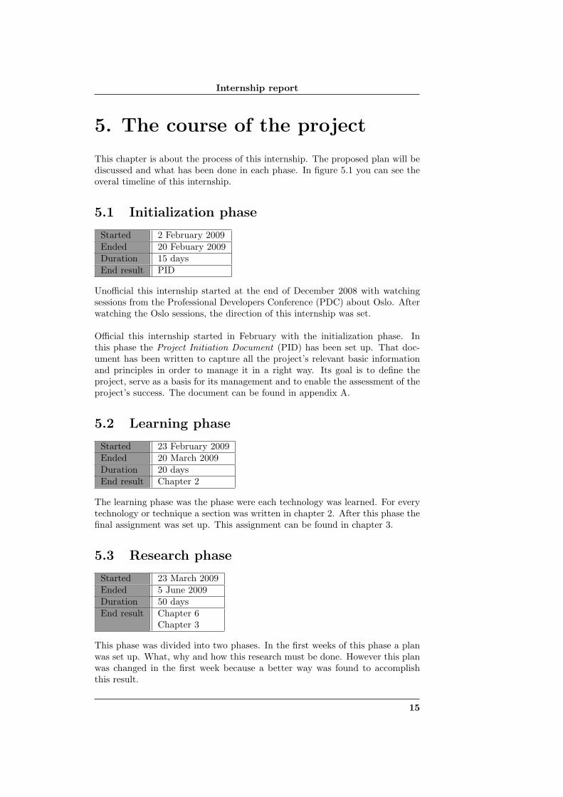
5.1 Initialization phase
Started 2 February 2009Ended 20 Febuary 2009Duration 15 daysEnd result PID
Unofficial this internship started at the end of December 2008 with watchingsessions from the Professional Developers Conference (PDC) about Oslo. Afterwatching the Oslo sessions, the direction of this internship was set.
Official this internship started in February with the initialization phase. Inthis phase the Project Initiation Document (PID) has been set up. That doc-ument has been written to capture all the project’s relevant basic informationand principles in order to manage it in a right way. Its goal is to define theproject, serve as a basis for its management and to enable the assessment of theproject’s success. The document can be found in appendix A.
5.2 Learning phase
Started 23 February 2009Ended 20 March 2009Duration 20 daysEnd result Chapter 2
The learning phase was the phase were each technology was learned. For everytechnology or technique a section was written in chapter 2. After this phase thefinal assignment was set up. This assignment can be found in chapter 3.
5.3 Research phase
Started 23 March 2009Ended 5 June 2009Duration 50 daysEnd result Chapter 6
Chapter 3
This phase was divided into two phases. In the first weeks of this phase a planwas set up. What, why and how this research must be done. However this planwas changed in the first week because a better way was found to accomplishthis result.
15
Internship report
The first plan was to compile the source code to get an external DLL-file andattach that file to the program. But whilst discussing this solution a better waycame up: After compiling, the program can use the source code directly fromthe memory. This method was a better and a faster way to accomplish.
This phase was marked by its ups and downs. Some of its requirements (seesection 6.2) take 5 hours to complete and some weeks, or when something waschanged others must be changed because the two weren’t compatible any more.
For example: when changing the MGrammar, the MSchema must change aswell that the output from the MGrammar is compatible with MSchema.
5.4 Project ending phase
Started 8 June 2009Ended 12 June 2009Duration 5 daysEnd result End presentation
Like the name of the phase it is the end of this project. The intern report docu-ment is finished and an end presentation is created. After the end presentationsome requirements that hasn’t finished will be made.
16 CHAPTER 5. THE COURSE OF THE PROJECT

Internship report
Figure 5.1: Overall timeline in this internship
CHAPTER 5. THE COURSE OF THE PROJECT 17
Internship report
6. Prototype OASA
This chapter provides the requirements for and the technical information aboutthe prototype OASA. OASA stands for Oslo Avanade Service Asset.
6.1 Overview
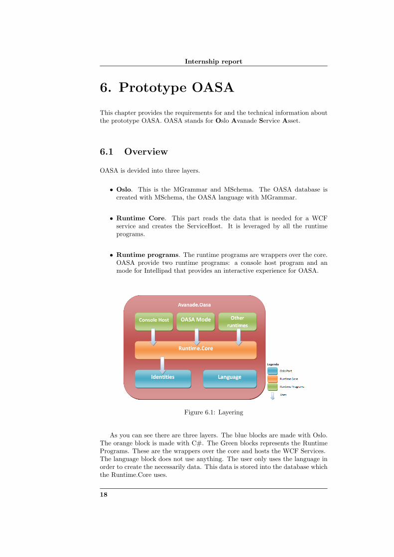
OASA is devided into three layers.
• Oslo. This is the MGrammar and MSchema. The OASA database iscreated with MSchema, the OASA language with MGrammar.
• Runtime Core. This part reads the data that is needed for a WCFservice and creates the ServiceHost. It is leveraged by all the runtimeprograms.
• Runtime programs. The runtime programs are wrappers over the core.OASA provide two runtime programs: a console host program and anmode for Intellipad that provides an interactive experience for OASA.
Figure 6.1: Layering
As you can see there are three layers. The blue blocks are made with Oslo.The orange block is made with C#. The Green blocks represents the RuntimePrograms. These are the wrappers over the core and hosts the WCF Services.The language block does not use anything. The user only uses the language inorder to create the necessarily data. This data is stored into the database whichthe Runtime.Core uses.
18
Internship report
6.2 Requirements
The purpose for the runtime is to reads the data, create and start WCF services.To accomplish this, requirements have been set up by the MoSCoW1 principle.The following table gives an overview and the status of the requirement.
Table 6.1: Requirements by the MoSCoW principleId What Rating0 Compile custom code1 Start WCF services at runtime2 MGrammar3 MSchema4 Read data from database5 Integration into Intellipad6 CodeDom to T4 templates7 Add Data contracts8 Add hosting in IIS10 Add Message contracts11 Dynamic update
LegendaMust have Could haveShould have Would have
6.3 Oslo
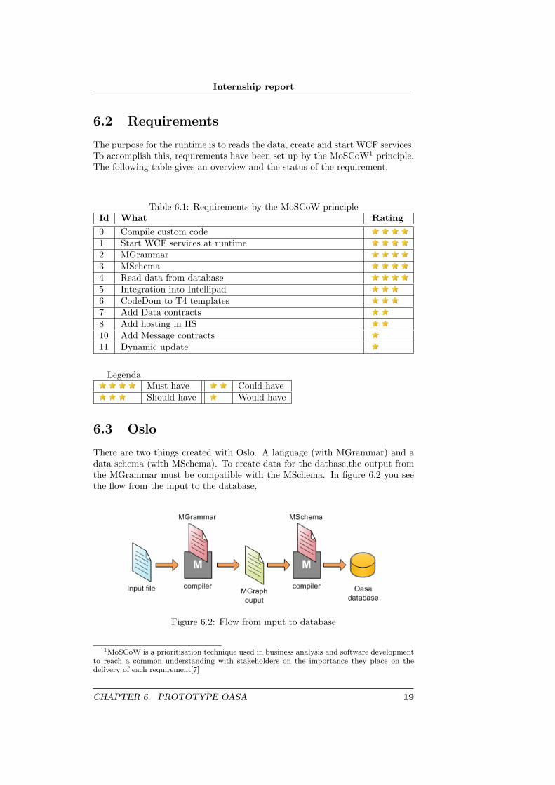
There are two things created with Oslo. A language (with MGrammar) and adata schema (with MSchema). To create data for the datbase,the output fromthe MGrammar must be compatible with the MSchema. In figure 6.2 you seethe flow from the input to the database.
Figure 6.2: Flow from input to database
1MoSCoW is a prioritisation technique used in business analysis and software developmentto reach a common understanding with stakeholders on the importance they place on thedelivery of each requirement[7]
CHAPTER 6. PROTOTYPE OASA 19
Internship report
The two gray boxes are components from the M framework. The followingfiles are used to create the Oasa database:
• Mg.exeThis use the MGrammar file to compile it into a mgx file.
• Mgx.exeThis use the compiled MGrammar file and the input file, which it createdby user, and create a MGraph file
• M.exeThis use the create MGraph file and the MSchema file to create a TSqlfile. This file can be loaded2 into the database.
6.3.1 Oasa Database (identities)
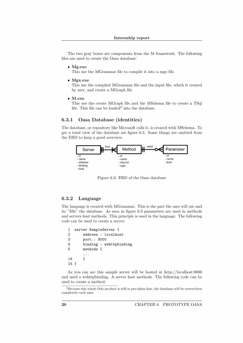
The database, or repository like Microsoft calls it, is created with MSchema. Toget a total view of the database see figure 6.3. Some things are omitted fromthe ERD to keep a good overview.
Figure 6.3: ERD of the Oasa database
6.3.2 Language
The language is created with MGrammar. This is the part the user will use andits ”fills” the database. As seen in figure 6.3 parameters are used in methodsand servers host methods. This principle is used in the language. The followingcode can be used to create a server:
1 server SampleServer {2 address : localhost3 port : 80004 binding : wshttpbinding5 methods {
...14 }15 }
As you can see this sample server will be hosted at http://localhost:8000and used a wshttpbinding. A server host methods. The following code can beused to create a method:
2Because this whole Oslo product is still in pre-alpha fase, the database will be overwrittencompletely each time
20 CHAPTER 6. PROTOTYPE OASA
Internship report
6 method SampleMethod {7 returnd : void8 logic { Console.WriteLine(text+text1);}9 parameters {10 text : System.String11 text1 : System.String12 }13 }
In line 8 you must specify the logic in C# code. In this Oslo version it is notpossible to enter spaces in the logic. To work around this problem a second wayis introduced to enter the C# code.
6 method SampleMethodWithExternalFile {7 returnd : void8 logic { #C:\\EnterFileNameAndPath.txt}9 parameters {10 text : System.String11 text1 : System.String12 }13 }
When the logic starts with a ”#” sign, the runtime will load the file and usethe logic in it.
6.4 C# Runtime
The runtime is build with C#. As seen in figure 6.1, the runtime it is dividedinto 2 parts, a core part and the runtime programs. The runtime programs willbe discussed later.
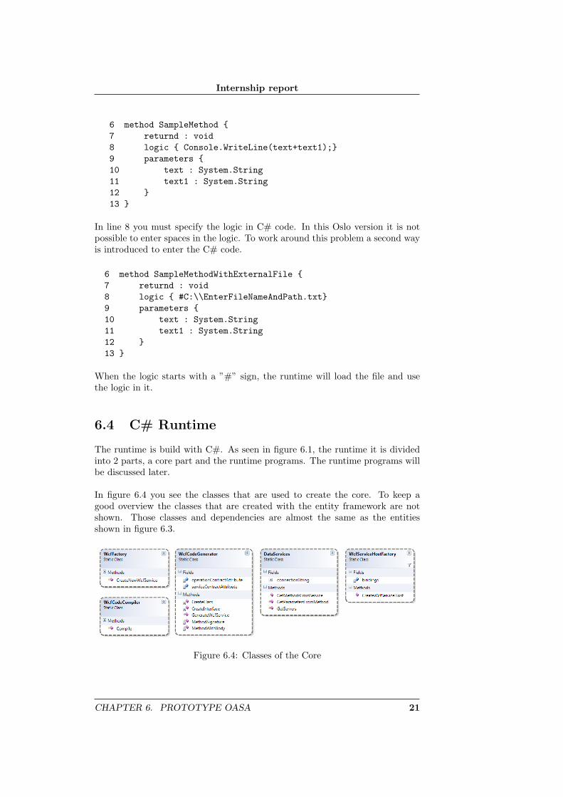
In figure 6.4 you see the classes that are used to create the core. To keep agood overview the classes that are created with the entity framework are notshown. Those classes and dependencies are almost the same as the entitiesshown in figure 6.3.
Figure 6.4: Classes of the Core
CHAPTER 6. PROTOTYPE OASA 21

Internship report
Class: WcfFactory
The class: WcfFactory is a facade3 of the core. A Runtime program can used itto send the server to. The WcfFactory will take care of the rest of the creatingsequence. See section 6.4.2 to get a beter understanding of the creating sequence.Although this class give a simple facade, every runtime program can use all theother classes.
Class: WcfCodeGenerator
The class: WcfCodeGenerator create the source code that is necessarily forthe WCF service. The creation of the source is divided into several privatemethods. Each method will take care of its own responsibility. By callingthe method GenerateWcfService a string will be returned, that contains thecomplete source code.
Class: WcfCodeCompiler
The class: WcfCodeCompiler just simply compile the generated source code.After compiling the source code, it will search for the type (the class) that theserver will be. The name of the type has the same name as the server.
Class: WcfServiceHostFactory
The WcfServiceHostFactory create the host environment for the service. Itassigns the address and binding of the service.
Class: DataServices
The class: DataServices provides a kind of Data access layer. All data requestgo through here.
3A facade is an object that provides a simplified interface to a larger body of code[8]
22 CHAPTER 6. PROTOTYPE OASA
Internship report
6.4.1 Runtime Program: Console Host
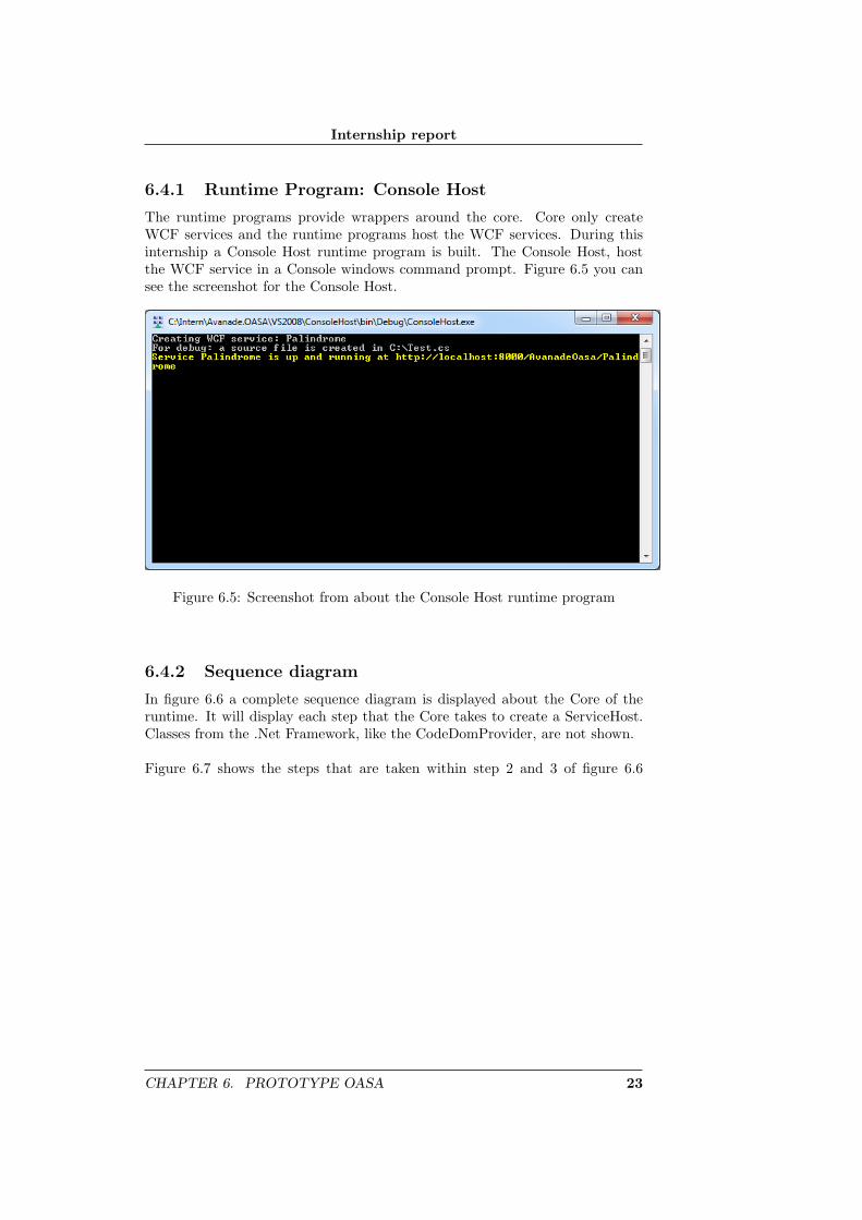
The runtime programs provide wrappers around the core. Core only createWCF services and the runtime programs host the WCF services. During thisinternship a Console Host runtime program is built. The Console Host, hostthe WCF service in a Console windows command prompt. Figure 6.5 you cansee the screenshot for the Console Host.
Figure 6.5: Screenshot from about the Console Host runtime program
6.4.2 Sequence diagram
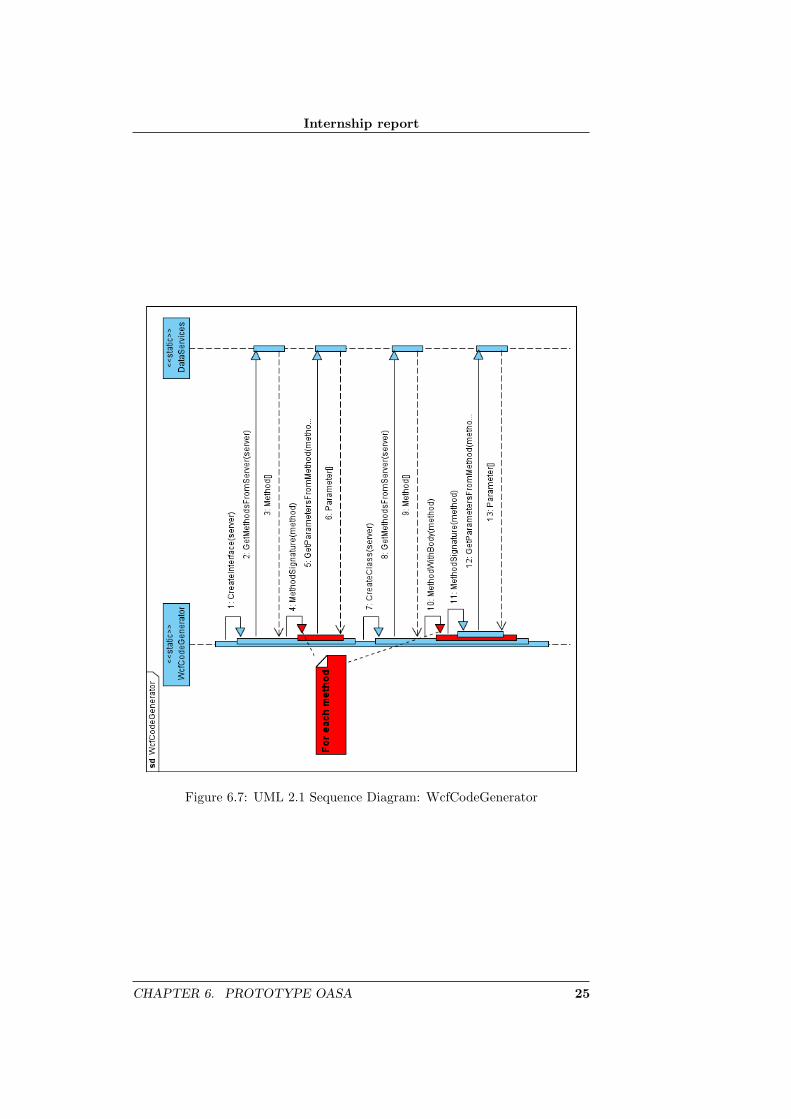
In figure 6.6 a complete sequence diagram is displayed about the Core of theruntime. It will display each step that the Core takes to create a ServiceHost.Classes from the .Net Framework, like the CodeDomProvider, are not shown.
Figure 6.7 shows the steps that are taken within step 2 and 3 of figure 6.6
CHAPTER 6. PROTOTYPE OASA 23

Internship report
Figure 6.6: UML 2.1 Sequence Diagram: Oasa Core
24 CHAPTER 6. PROTOTYPE OASA
Internship report
Figure 6.7: UML 2.1 Sequence Diagram: WcfCodeGenerator
CHAPTER 6. PROTOTYPE OASA 25
Internship report
7. Problems and solutions
7.1 T4 templates and CodeDomProvider
The WcfCodeGenerator uses the CodeDomProvider (CDP). The CDP can beused to create source code. The code generator generate code in every .NETlanguage. By using the CDP you are almost certain that the code that is gener-ated is valid. The negative point about the CDP is that modifications are hardto do and it is inflexible.
Another way to generate code is T41 templates. These templates can be usedto generate any text files. The big advantage of T4 when comparing to CDP isthat the templates can easily be changed and it is very flexible.
In the final version of the prototype, code generation is done with CDP howeverin a future version it should be done with T4 templates. During this internshipan attempt was made to integrate T4 instead of CDP but unfortunately thistook too much time and was suspended.
1Microsoft Text Template Transformation Toolkit
26

Internship report
8. Conclusion
8.1 The answer
The Objective from section 3.2 was:
The objective of this research is contributing to the development of ACA.NETbyexamining how to start WCF services at runtime with Oslo.
I have proven that it is possible to create WCF services at runtime with anOslo approach. I believe that Oslo can greatly contribute to ACA.NET. I don’thave the knowledge to say that something like OASA will replace ACA.NET.With the OASA language it is very easy and fast to create WCF services. Youonly deliver the data for the WCF service and the OASA runtime will createand host the WCF service for you.
8.2 Microsoft Oslo
Note: My opinions are based on the Oslo January 2009 CTP Refresh version
8.2.1 Positive points
• It takes little time to create a relative complex grammar.
• Intellipad is very extendable. It is possible to create new modes with C#or extensions with Python.
• Oslo is released under Open Specification Promise. This means that verybody can change the platform to create extensions or let it work withother databases like MYSQL from Sun Microsystems.
8.2.2 Negative points
• Intellipad gives strange error massages, like: ”Expected one token, butfound many”. Many of these errors can be fixed to change something inthe grammar, like removing a ”;” sign, and then undo the change.
• When the data is in the repository you don’t need Oslo anymore.
• You still need a MSchema in order to store your MGrammar output(MGraph) into the database.
27
Internship report
A. Project Initiation Document
A.1 Introduction
A.1.1 Purpose of this document
This document is written to capture all the project’s relevant basic informationand principles in order to manage it in a right way. Its goal is to define theproject, serve as a basis for its management and to enable the assessment of theproject’s success.
This Internship report (or PID) covers the following fundamental project as-pects:
• What is the aim of the project?
• Why it is important to achieve these goals?
• Who are involved in the project management and what are their roles andresponsibilities?
A.2 Composition of the document
This Internship report is segmented into two sections as to indicate which partswill be updated and hence will have newer versions as the project proceeds: astatic part and a dynamic part:
The “static” part consists of the following chapters:
• Background (Chapter A.3)
• Project Definition (Chapter A.4)
• Project Organisation Structure (Chapter A.5)
• Project Controls (Chapter A.6)
• Communication plan (Chapter A.7)
The “dynamic” part consists of the Appendices:
• Initial Project Plan (Appendix: A.8)
• Business Case (Appendix: A.9)
28
Internship report
A.3 Background
A.3.1 The Context of the project
Avanade
In 2000, Microsoft and Accenture came together to create Avanade. A jointventure designed to meet the growing demand of Microsoft-based services amongenterprises worldwide. In the past 9 years, Avanade has grown to become oneof the largest Microsoft oriented companies in the world. They have over 9000employees of which 180 are working in the Netherlands.
ACA.NET
ACA.NET (Avanade Connected Architectures) is a framework that describeshow to successfully build .NET applications. It compliments and extends theMicrosoft .NET Framework with common architecture services that acceleratethe development process. It is also a set of reusable architecture components thatprovide valuable services and assistance to developers who are building .NETapplications.1
Microsoft “Oslo” Modeling Platform
Currently Microsoft is developing a new platform named: Oslo. This platformis a set of technical investments that aim to significantly simplify designing,building, managing and scaling service-oriented and composite applications thatcan span from the enterprise to the Internet.2
The Core of the platform is formed by Domain Specific Models (DSL’s), lan-guage and tools. With Oslo you can create your own tools to build and generatesoftware systems. To establish this, the Oslo platform provides:
• A language, M (MGrammer), to write down your domain models.
• A tool, Quadrant, to visalise your models.
• A storage place, Repository, to manage your models.
• A collection of pre-made models and languages.
1Source: http://www.avanade.com/whatwedo/deliverydetail.aspx?deliveryid=22Source: http://msdn.microsoft.com/nl-nl/library/cc709420(en-us).aspx
APPENDIX A. PROJECT INITIATION DOCUMENT 29
Internship report
A.4 Project Definition
A.4.1 Project goals
A research on Oslo with the main question: What can Oslo mean to ACA.NET?The focus area of the research will be the M language.
A.4.2 Selected solution or approach
First the ACA.NET , WCF and Oslo must be understood; this included thebasic of Service-Oriented Applications (SOA’s) what they are and why they areused. On the intranet of Avanade is a lot of information available on thesesubjects except Oslo. For Oslo the main entry point for information will be theMSDN internet sites and the video sessions of the PDC2008.During or after this “learning stage”, a research plan will be made.
A.4.3 Project scope
As formulated in the ’project goals’ there will be a research about Oslo. Onlythe M language will be studied. The others, like Quadrant, will be disregarded.
A.4.4 Products and/or outcome
The following products/documents belong to the outcome:
A research planThis document formulates the main research question.
Findings and conclusion reportAll findings and conclusion(s) in the research will be explained in thisdocument.
ExamplesExamples to support the findings and conclusions. The ’findings andconclusion report’ will reference to an example when necessarily.
A.4.5 Exclusions
The exclusions are as follow:
• There will not be made any changes in the current ACA.NET framework.
• Conclusions will only be based on Mgrammer. Quadrant, Repository andpremade models & language will be excluded in the conclusion.
A.4.6 Dependencies
• The “Oslo” platform is in pre-alpha phase. This means that Oslo maybe expanded with new functionalities and that the current functionalitiesmay change or even disappear.
30 APPENDIX A. PROJECT INITIATION DOCUMENT
Internship report
A.4.7 Preconditions
The following preconditions must be present for this project to achieve:
• All documentations about ACA.NET must be available.
• In the case of technical problems the internship supervisor should responsewithin 2 workdays.
• In the research phase, a state of progress about the research must bemailed to the internship supervisor very week.
A.4.8 Assumptions
• During all phases the Avanade intranet will be available for education andother information.
APPENDIX A. PROJECT INITIATION DOCUMENT 31
Internship report
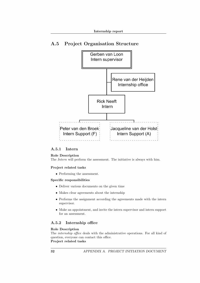
A.5 Project Organisation Structure
A.5.1 Intern
Role DescriptionThe Intern will perform the assessment. The initiative is always with him.
Project related tasks
• Performing the assessment.
Specific responsibilities
• Deliver various documents on the given time
• Makes clear agreements about the internship
• Performs the assignment according the agreements made with the internsupervisor.
• Make an appointment, and invite the intern supervisor and intern supportfor an assessment.
A.5.2 Internship office
Role DescriptionThe internship office deals with the administrative operations. For all kind ofquestion, everyone can contact this office.Project related tasks
32 APPENDIX A. PROJECT INITIATION DOCUMENT

Internship report
• Provides information
• Gives advice and mediation during problems
Specific responsibilities
• Archive documents.
A.5.3 Intern supervisor
Role DescriptionThe intern supervisor will guide the intern with the technical content. TheIntern supervisor is the first person in line that the intern must contact withquestion, request or what so ever.
Project related tasks
• Ensures that the work will carried out accordance to the internship objec-tives.
• Meet with the intern support (F) and discuss the social and professionalattitude about the intern.
• Check and sign the log.
• Sign the intern report when seen.
Specific responsibilities
• Guide the intern with technical content.
• Guide the intern with creating the project plan (this document).
• Guide the intern with specifying the project target.
A.5.4 Intern Support (A)
Role DescriptionThe intern support (A) is an addition support from Avanade. He or she is therefor tasks like:
• Delivery management
• Plans that the intern may have in- our outside the boundaries of thisproject.
• For contact both inside and outside Avanade.
• Problems or question that the intern may have.
Specific responsibilities
• Support the intern during this internship when needed.
APPENDIX A. PROJECT INITIATION DOCUMENT 33
Internship report
A.5.5 Intern Support (F)
Role DescriptionThe Intern support (F), from Fontys, will ensure that the internship is in linewith the Fontys objectives.
Project related tasks
• Guide the intern throughout the internship
• Guide the intern while writing his intern report
• Review the report and discuss it with the intern
• Visit the company and discuss the progress so far based on the submitteddocuments
• Gives feedback at the end of the internship about the company, contract,guidance etc . . .
Specific responsibilities
• Evaluate the intern report
34 APPENDIX A. PROJECT INITIATION DOCUMENT
Internship report
A.6 Project Controls
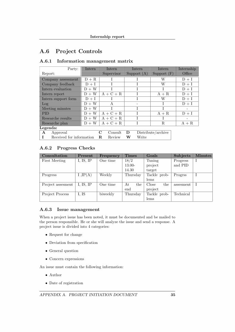
A.6.1 Information management matrix
Party: Intern Intern Intern Intern InternshipReport: Supervisor Support (A) Support (F) OfficeCompany assessment D + R I I W D + ICompany feedback D + I I I W D + IIntern evaluation D + W I I I D + IIntern report D + W A + C + R I A + R D + IIntern support form D + I I I W D + ILog D + W A - I D + IMeeting minutes D + W I I I -PID D + W A + C + R I A + R D + IResearche results D + W A + C + R I I -Researche plan D + W A + C + R I R A + R
Legenda:A Approval C Consult D Distribute/archiveI Received for information R Review W Write
A.6.2 Progress Checks
Consultation Present Frequency Times Goals Subjects MinutesFirst Meeting I, IS, IP One time 18/2
13.00-14.30
Tuningprojecttarget
Progressand PID
I
Progress I ,IP(A) Weekly Thursday Tackle prob-lems
Progrss I
Project assesment I, IS, IP One time At theend
Close theproject
assesment I
Project Process I, IS biweekly Thursday Tackle prob-lems
Technical
A.6.3 Issue management
When a project issue has been noted, it must be documented and be mailed tothe person responsible. He or she will analyze the issue and send a response. Aproject issue is divided into 4 categories:
• Request for change
• Deviation from specification
• General question
• Concern expressions
An issue must contain the following information:
• Author
• Date of registration
APPENDIX A. PROJECT INITIATION DOCUMENT 35
Internship report
• Reference number
• Description
• Priority3
• Impact analysis
• Offered for information sent to (optional)
The response must contain the following information:
• Author
• Decision/reaction
• Date of decision
When the issue was send to someone for information, the response must also besend to those people.
3high, normal or low
36 APPENDIX A. PROJECT INITIATION DOCUMENT
Internship report
A.7 Communication plan
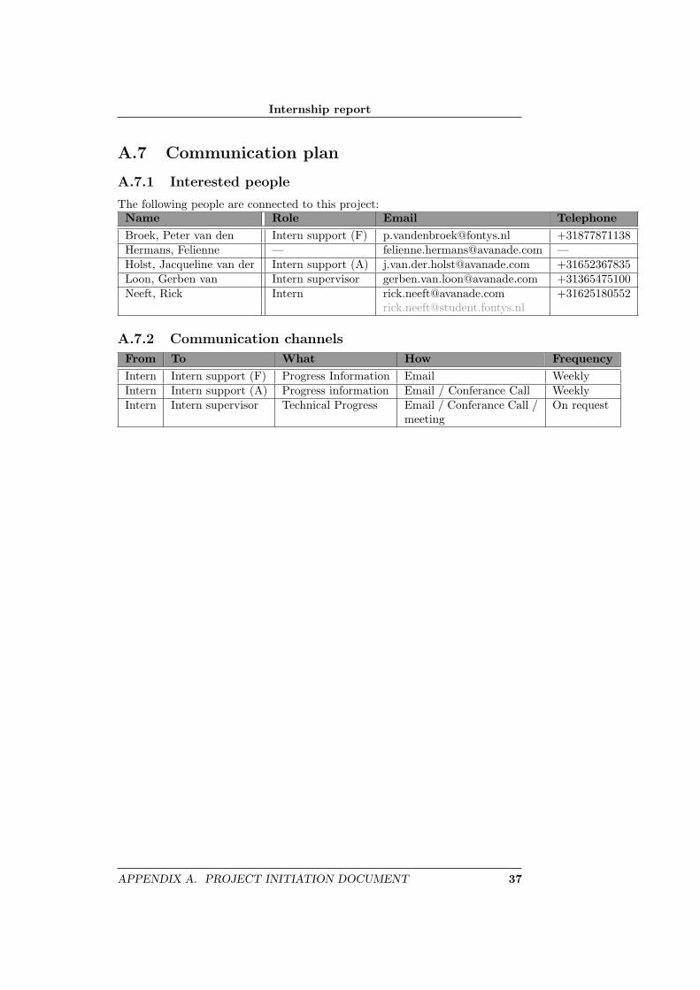
A.7.1 Interested people
The following people are connected to this project:Name Role Email TelephoneBroek, Peter van den Intern support (F) [email protected] +31877871138Hermans, Felienne — [email protected] —Holst, Jacqueline van der Intern support (A) [email protected] +31652367835Loon, Gerben van Intern supervisor [email protected] +31365475100Neeft, Rick Intern [email protected] +31625180552
A.7.2 Communication channels
From To What How FrequencyIntern Intern support (F) Progress Information Email WeeklyIntern Intern support (A) Progress information Email / Conferance Call WeeklyIntern Intern supervisor Technical Progress Email / Conferance Call /
meetingOn request
APPENDIX A. PROJECT INITIATION DOCUMENT 37
Internship report
A.8 Initial Project Plan
A.8.1 Project setup
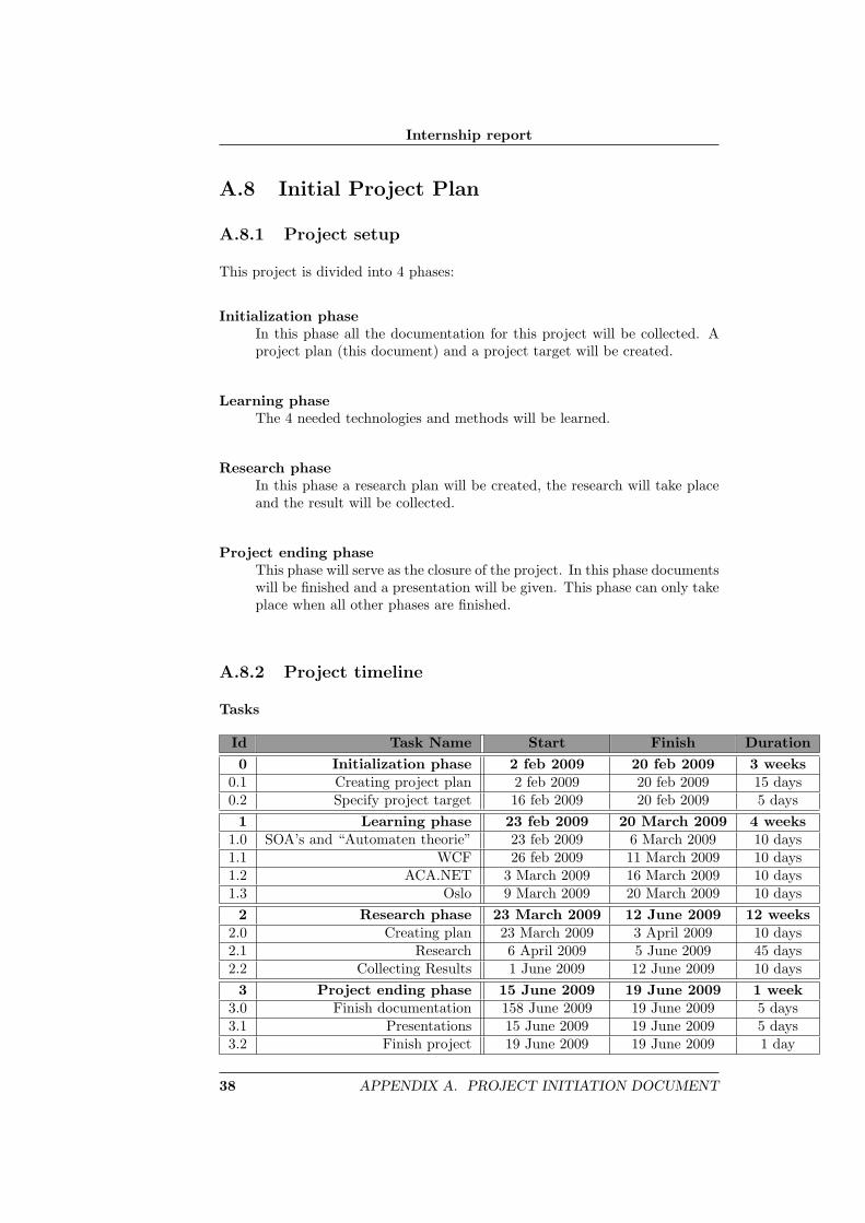
This project is divided into 4 phases:
Initialization phaseIn this phase all the documentation for this project will be collected. Aproject plan (this document) and a project target will be created.
Learning phaseThe 4 needed technologies and methods will be learned.
Research phaseIn this phase a research plan will be created, the research will take placeand the result will be collected.
Project ending phaseThis phase will serve as the closure of the project. In this phase documentswill be finished and a presentation will be given. This phase can only takeplace when all other phases are finished.
A.8.2 Project timeline
Tasks
Id Task Name Start Finish Duration0 Initialization phase 2 feb 2009 20 feb 2009 3 weeks
0.1 Creating project plan 2 feb 2009 20 feb 2009 15 days0.2 Specify project target 16 feb 2009 20 feb 2009 5 days
1 Learning phase 23 feb 2009 20 March 2009 4 weeks1.0 SOA’s and “Automaten theorie” 23 feb 2009 6 March 2009 10 days1.1 WCF 26 feb 2009 11 March 2009 10 days1.2 ACA.NET 3 March 2009 16 March 2009 10 days1.3 Oslo 9 March 2009 20 March 2009 10 days
2 Research phase 23 March 2009 12 June 2009 12 weeks2.0 Creating plan 23 March 2009 3 April 2009 10 days2.1 Research 6 April 2009 5 June 2009 45 days2.2 Collecting Results 1 June 2009 12 June 2009 10 days
3 Project ending phase 15 June 2009 19 June 2009 1 week3.0 Finish documentation 158 June 2009 19 June 2009 5 days3.1 Presentations 15 June 2009 19 June 2009 5 days3.2 Finish project 19 June 2009 19 June 2009 1 day
38 APPENDIX A. PROJECT INITIATION DOCUMENT
Internship report
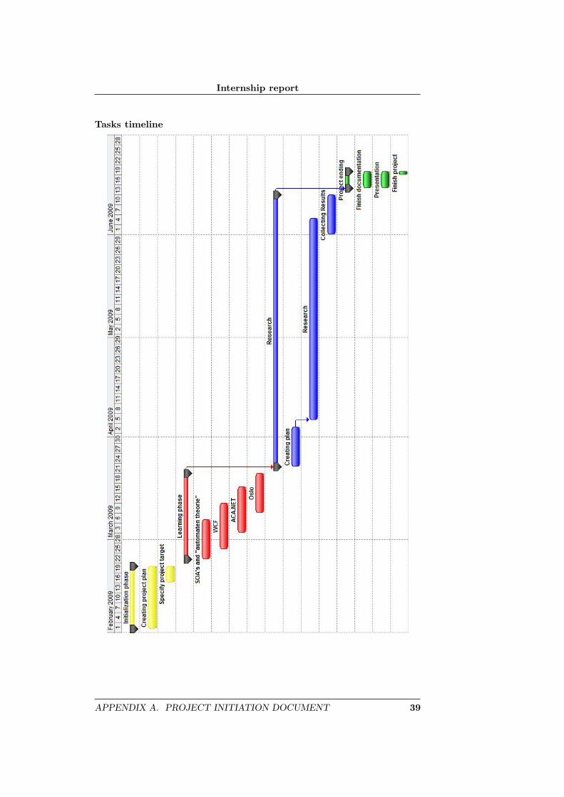
Tasks timeline
APPENDIX A. PROJECT INITIATION DOCUMENT 39
Internship report
A.9 Business Case
A.9.1 Introduction
This appendix contains the considerations to start the current project. It formsthe justification, describes the benefits and potential project risks. The foun-dations of the project will be frequently evaluated on the basis of this BusinessCase. The Business Case starts with a description of the considerations madefor the project.
A.9.2 Reason
This project has the purpose to find out what “Oslo” can mean to ACA.Netwith the focus on the “M” language. Avanade asserts continue to evolve andevery new technology, from Microsoft, will be examine.
A.9.3 Benefits
Although the research shall not have direct benefits, the following benefits canbe expected:
• By implementing Oslo into ACA.NET, it may be using less resources.
• The total development time when using ACA.NET may decrease.
• The total custom lines of code may decrease, therefore less error’s can bemade and fewer code must be maintained.
A.9.4 Risks
Microsoft cancelled Oslo developmentMicrosoft wouldn’t release a commercial release if they would cancel theOslo development. There wouldn’t be any reason to continue this project.The present findings and conclusions will be reported.
40 APPENDIX A. PROJECT INITIATION DOCUMENT
Internship report
Glossary
ACA.NET Avanade Connected ArchitecturesDSL for designing WCF services.
CDP CodeDomProviderPart of .NET framework that can generate and compile .NETcode.
DSL Domain Specific LanguageA language that is specific on a special domain, like ACA.NET.
OASA Oslo Avanade Serivce AssetPrototype for creating and executing WCF services at runtime.
SOA Service Oriented ArchitectureSet of components which can be invoked, and whose interfacedescriptions can be published and discovered.[2]
T4 Microsoft’s Text Template Transformation ToolkitTemplate for generating any text file.
WCF Windows Communication Foundation.NET Framework technology for building and hosting service ori-ented applications
41
Internship report
Bibliography
[1] Avanade Global http: // avanade. com/ about/ index. aspx
[2] Web Services Glossary, www. w3. org/ TR/ ws-gloss/
[3] Web Services Glossary, http: // www. w3. org/ TR/ ws-gloss/ #service
[4] Msdn Oslo, http: // msdn. microsoft. com/ Oslo
[5] ”Oslo” - the language, http: // channel9. msdn. com/ pdc2008/ TL27/
[6] MEX endpoints, Essential Windows Communication FoundationISBN: 0-321-44006-4Authors: Steve Resnick, Richard Crane, Chris Bowen.
[7] MoSCoW Principle http: // en. wikipedia. org/ wiki/ MoSCoW_ Method
[8] Facade, http: // en. wikipedia. org/ wiki/ Facade_ pattern
42


![[Internship Report] folder... · Web view[Internship Report] [Internship Report] 3 [Internship Report] Prince Mohammed Bin Fahd University College of Computer Engineering and Science](https://img.pdfslide.us/doc/110x75/5adbc5e37f8b9add658e5f6e/internship-report-folderweb-viewinternship-report-internship-report-3-internship.jpg)