Embed Size (px)
Citation preview
Internship Report
Master in Product Design Engineering
Study on water-assisted injection molding
technology
Name: Viveganandan Ravikumar.
Leiria, June,2017

This page was intetionally left blank
Internship Report
Master in Product Design Engineering
Study on water-assisted injection molding
technology
Name:Viveganandan Ravikumar
Internship developed under the supervision of Doctor Fabio Simões professor at the School of Technology and Management of the Polytechnic Institute of Leiria
Leiria, June.2017

ii
This page was intetionally left blank

iii
Acknowledgements
I would like to thank all professors of the mechanical engineering department of the
School of Technology and Management and to all teachers from other departments for all
the knowledge they have given me throughout my journey in this institution. I must thank
my professor Dr. Fabio Simões for giving me an opportunity to gain exposure and
knowledge about molds and to complete my report on my internship throughout out my
course. I would also like to thank all the people from Moldetipo for helping me and
passing over their knowledge to me.

iv
This page was intetionally left blank
v
Resumo (in Portuguese)
Este relatório compreende uma apresentação e análise detalhada do estágio feito na
Moldetipo. As áreas que são descritas e discutidas em detalhes incluem moldação por
injeção, vários processos utilizados na fabricação de um molde, defeitos num molde e
defeitos em peças injetadas. Também analisa a tecnologia de moldação por injeção
assistida por água. Este relatório começa por explicar a moldação por injeção e as
máquinas de moldação por injeção, seguidas de partes constituintes de um molde e os
diferentes processos envolvidos na fabricação de um molde. Este relatório também
compreende um estudo de caso de moldação por injeção assistida por água (WAIM) e a
formação de vazios nas peças fabricadas por WAIM. Além disso, inclui um estudo de caso
sobre diferentes parâmetros que afetam o processo WAIM.
Palavras-chave: Moldação por injeção, peças padrão, defeitos, moldação por
injeção assistida por água.

vi
This page was intetionally left blank
vii
Abstract
This report comprises of a detailed presentation and analysis of the internship that is
done at Moldetipo. The areas that are described and discussed in detail include, injection
molding, various processes used in making a mold, defects in a mold and defects in part . It
also analyses the technology of Water Assisted Injection Molding. This report starts by
explaining injection molding and injection molding machines, followed by parts of a mold
and different process involved in manufacturing a mold. This report also comprises of case
study of Water Assisted Injection Molding (WAIM) and the void formation in the parts of
WAIM machined. Also, a case study about different parameters that affect the WAIM
process.
Keywords: Injection molding, Standard parts, Defects, Water Assisted
Injection Molding.

viii
This page was intetionally left blank
ix
List of figures
Figure 1-Injection Molding machine[2] ....................................................................... 3
Figure 2- The Barrel & the zones.[4] ........................................................................... 4
Figure 3- Working cycle of an injection mold.[4] ....................................................... 5
Figure 4- Hydraulic clamp & Toggle clamp.[2] .......................................................... 6
Figure 5-The Deep Rib & Core Cavity approach.[7] ................................................... 7
Figure 6-Two-plate mold. (a) Closed & .(b) Opened.[2] ............................................. 8
Figure 7-Three-plate mold. (a) Closed & .(b) Opened.[2] ........................................... 8
Figure 8-Sleeve Ejection.[8] ........................................................................................ 9
Figure 9- Push back pin when the mold opens during ejection.[8] ............................ 10
Figure 10- Stripper plate ejection representation.[8] ................................................. 10
Figure 11- Hot runner for multiple cavity mold[8] .................................................... 11
Figure 12- Section view of a sprue[8]. ....................................................................... 11
Figure 13- Cooling channel circuit in an example mold.[10] .................................... 12
Figure 14- Single cavitymold with feed system[8] .................................................... 13
Figure 15- Multi-cavity mold with feed system.[8] ................................................... 13
Figure 16- An example mold with plates named.[11]................................................ 14
Figure 17- Ejector set (Ejector plates)[11] ................................................................. 14
Figure 18- Tapered interlocks and Straight side interlocks.[11] ................................ 15
Figure 19- Round end ejector pin.[11] ....................................................................... 15
Figure 20- An example image of a Lifter [11] .......................................................... 16
Figure 21- Slider in opened position & Slider in closed position.[11] ...................... 16
Figure 22- A standard hot runner system.[11] ........................................................... 17
Figure 23- Flat component.[11] ................................................................................. 18
Figure 24-Spirial component.[11] .............................................................................. 18
Figure 25- Sink marks indicated in a part.[17] .......................................................... 22
Figure 26- Short shot indicating incomplete component.[17] ................................... 23
Figure 27- An image indicating the difference between the required part and the part
that has warpage.[18] ........................................................................................................... 23
Figure 28- Burn mark identified in a part.[17] ........................................................... 23
Figure 29- a part with flashes in it.[17] ...................................................................... 24
Figure 30- A sprue Gate.[19] ..................................................................................... 24
x
Figure 31- A Tab gate.[19] ........................................................................................ 25
Figure 32- An Edge gate.[19] .................................................................................... 25
Figure 33- A Submarine gate.[19] ............................................................................. 26
Figure 34- A common 3-Axis CNC machine.[23] .................................................... 30
Figure 35- A steel bar before being machined as mold plates.[27] ........................... 31
Figure 36- Face milling operation.[24] ...................................................................... 32
Figure 37- A schematic representation of EDM process .[25] .................................. 34
Figure 38- The overall setup of Electro Discharge Machining.[26] .......................... 35
Figure 39- A working Wire-cutting EDM machine.[27] ........................................... 36
Figure 40- The process layout of a wire cutting EDM machine.[28] ........................ 36
Figure 41- The Laser Scanning device.[29] ............................................................... 37
Figure 42-Different stages in Gas-assisted injection molding.[31] ........................... 40
Figure 43- Effect of cooling in an External GAIM part.[31] ..................................... 42
Figure 44- The steps for a short-shot WAIM.[32] ..................................................... 43
Figure 45- The steps for a Full-shot WAIM.[32] ...................................................... 44
Figure 46- PvT diagram of a typical semi-crystalline polymer.[33] ......................... 46
Figure 47- Void formation with heat flow inside a part.[33] ..................................... 47
Figure 48- Varying Residual wall thickness in the curved section of a part.[33] ...... 47
Figure 49-Water penetration on mold temperature.[34] ............................................ 49
Figure 50- Water penetration on Delay time [34] ...................................................... 50
Figure 51-Effect plotted at 40°C.[33] ........................................................................ 51
Figure 52- Effect plotted at holding time of 5sec.[33] .............................................. 52
Figure 53-The Effect at holding time of 5sec.[33] .................................................... 52
Figure 54- The Effect at holding time of 10sec.[33] ................................................. 53
xi
List of tables
Table 1- Commonly used material for mold andits applications.[15] ....................... 20
Table 2- Chemical composition of P20 steel.[15] ...................................................... 20
Table 3- P20 Tool Steel Equivalent Steel Grades[15] ............................................... 20
Table 4- Mold plate numbering and the common materials it is made of. ................ 21
Table 5-Commonly used materials.[16] [17] ............................................................ 22
Table 6- Common Defects in injection molding. ....................................................... 22
Table 7- The Melt Flow Rate of different plastic resin.[24] ...................................... 27

xii
This page was intetionally left blank

xiii
List of acronyms
CNC – Computer Numerical Control.
MFR – Melt Flow Rate.
GAIM – Gas Assisted Injection Molding
WAIM – Water Assisted Injection Molding.
PL – Parting Line
W – Width of the gate.
L – Length of the gate.
h – Height of the gate.
t – thickness of the gate.

xiv
This page was intetionally left blank
xv
Table of Contents
ACKNOWLEDGEMENTS III
RESUMO (IN PORTUGUESE) V
ABSTRACT VII
LIST OF FIGURES IX
LIST OF TABLES XI
LIST OF ACRONYMS XIII
TABLE OF CONTENTS XV
1. INTRODUCTION 1
2. INJECTION MOLDING 1
2.1. The injection mold. 1
2.2. The injection molding machine. 2
2.3. Design of an injection molding machine. 2
2.4. Injection Units. 5
2.5. Clamping. 6
3. MOLD CONSTRUCTION. 7
3.1. Two-plate mold. 7
3.2. Three-plate mold. 8
3.3. Ejection Techniques. 9
3.4. Feed system. 10
3.5. Cooling system. 11
3.6. Standard parts of a mold. 12 3.6.1. Single cavity mold. 12
3.6.2. Multi cavity mold. 13
3.6.3. Standard mold set with bars and sleeves 13
3.6.4. Ejector pins and special components for ejection. 15
3.6.5. Core moving elements. 16
3.6.6. Runner system components 16
3.6.7. Cascading flow components. 17
xvi
3.7. Material selection of an injection mold. 18
3.8. Defects in injection mold 22
3.9. Gates. 24
3.10. Critical factors for injection molding. 26
4. ACTIVITIES DEVELOPED 29
4.1 CNC 30
4.2. Milling 30 4.2.1. End mill materials. 32
4.2.2. Observations 33
4.3. Production/Bancada. 33
4.4. Erosion 34
4.5. Injection department. 37
4.6. Dimensional analysis stage. 37
5. WATER ASSISTED INJECTION MOLDING (WAIM). 39
5.1. Gas assisted injection molding.(GAIM). 39
5.2. Water assisted injection molding.(WAIM). 42
5.3. Water assisted injection molding at MoldeTipo 45
5.4. Important parameters for WAIM. 48
6. CONCLUSION. 55
REFERENCES 57
APPENDICES 62
GLOSSARY 64


1
1. Introduction
This report comprises the information about the internship in company Moldetipo.
Ltd. In this internship the guidance was given by professor Fabio Simões of Instituto
Politécnico de Leiria. The internship is as a part of the course Master’s in Product Design
Engineering in IPL, and it has a duration of about nine months. During this nine months, it
was possible to acquire information about injection molding and about getting customers.
Along with this, it was possible to learn about a technology called “Water Assisted
Injection Molding”(WAIM). So, this report includes a separate section about WAIM, void
formation in WAIM and the parameters that affect for the betterment for the process to
make a perfect part.
The internship began by the CNC department at the very beginning. Followed by
Production, Erosion, Injection and Design. The duration in each department depends upon
the time it takes to understand the main theme of the works being done in each department
respectively. Despite being in each of the departments, the work was also done in the
Dimensional control department at the same time. So, this report consists of a brief
information about molds and molding machines at the beginning, after which it has the
standard components used in a mold. Explaining all this is extended by my experience and
knowledge that was gained during the period of internship. The report concludes with a
study of Water Assisted-Injection Molding and a case study information about the
parameters that affects the WAIM process.


1
2. Injection molding
Injection moulding is a technique of producing an object as the name itself infers, the
object is produced by injecting its molten raw material. Which is then directed into a
cavity, which will be shaped according to the shape of the product. Thereby, the product of
the required shape and material is moulded by injection moulding. In Injection molding the
polymer is heated to a highly plastic state and forced to flow under high pressure into a
mold cavity, where it solidifies. The part is then removed from the cavity. The process
produces discrete components. Also, there are multiple cavity molds which is used to
produce multiple parts in a single cycle.
The objective here is manufacturing a mold. The cost too matters while designing a
mold. It should be worth it and high in quality as most of them are for mass production.
2.1. The injection mold.
If plastic is injected into the mould cavity, this is called plastic injection moulding.
These plastics are thermoplastics which, when heated at high temperatures melt and when
cooled regain their solid state [1].An injection mould is comprised of several elements.
Figure 1- Injection mould elements.[2]
Where,
2
1. Top Clamping Plate
2. Runner plate
3. Fixed Cavity plate
4. Movable Core plate
5. Ejector Pin support plate
6. Spacer Block
7. Ejector Retainer plate
8. Ejector plate
9. Bottom Clamping Plate
Injection moulding is used to make many products such as wire spools, packaging,
bottle caps, automotive parts and components, .etc.
2.2. The injection molding machine.
The injection machine is a machine that plasticizes the molding material inside the
heating cylinder and injects this into the mold tool to create the molded product by
solidifying inside it.
The injection machine is constructed of a mold clamping device that opens and
closes the mold tool, and device that plasticizes and injects the molding material. There are
several types in the injection machines, and the difference is made by how these two
devices are arranged.
(1) Horizontal injection machine : Both mold clamping device and injection
device compounded horizontally.
(2) Vertical injection machine: Both mold clamping device and injection
device compounded vertically
2.3. Design of an injection molding machine.
The Injection machine will be of different types, upon which the type that we want
depends upon the volume, clamping pressure, nozzle structure and injection mechanism.
3
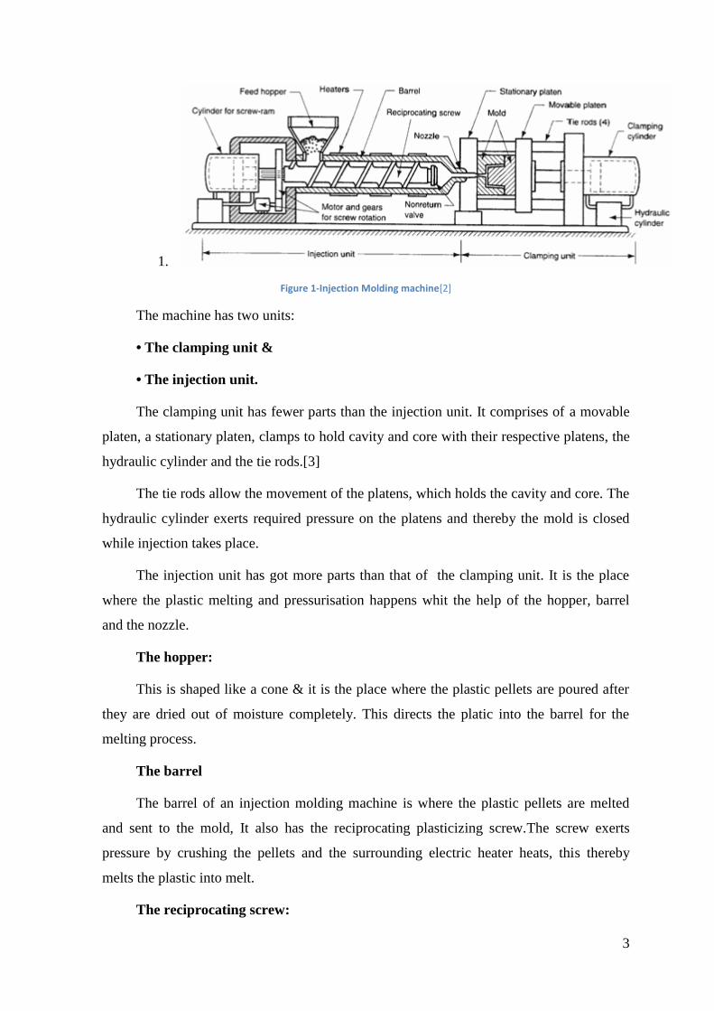
1.
Figure 1-Injection Molding machine[2]
The machine has two units:
• The clamping unit &
• The injection unit.
The clamping unit has fewer parts than the injection unit. It comprises of a movable
platen, a stationary platen, clamps to hold cavity and core with their respective platens, the
hydraulic cylinder and the tie rods.[3]
The tie rods allow the movement of the platens, which holds the cavity and core. The
hydraulic cylinder exerts required pressure on the platens and thereby the mold is closed
while injection takes place.
The injection unit has got more parts than that of the clamping unit. It is the place
where the plastic melting and pressurisation happens whit the help of the hopper, barrel
and the nozzle.
The hopper:
This is shaped like a cone & it is the place where the plastic pellets are poured after
they are dried out of moisture completely. This directs the platic into the barrel for the
melting process.
The barrel
The barrel of an injection molding machine is where the plastic pellets are melted
and sent to the mold, It also has the reciprocating plasticizing screw.The screw exerts
pressure by crushing the pellets and the surrounding electric heater heats, this thereby
melts the plastic into melt.
The reciprocating screw:
4
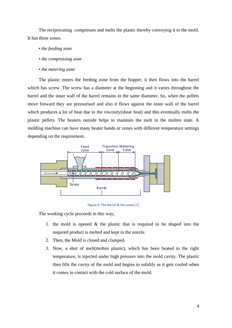
The reciprocating compresses and melts the plastic thereby conveying it to the mold.
It has three zones.
• the feeding zone
• the compressing zone
• the metering zone
The plastic enters the feeding zone from the hopper, it then flows into the barrel
which has screw .The screw has a diameter at the beginning and it varies throughout the
barrel and the inner wall of the barrel remains in the same diameter. So, when the pellets
move forward they are pressurised and also it flows against the inner wall of the barrel
which produces a lot of heat due to the viscosity(shear heat) and this eventually melts the
plastic pellets. The heaters outside helps to maintain the melt in the molten state. A
molding machine can have many heater bands or zones with different temperature settings
depending on the requirement.
Figure 2- The Barrel & the zones.[4]
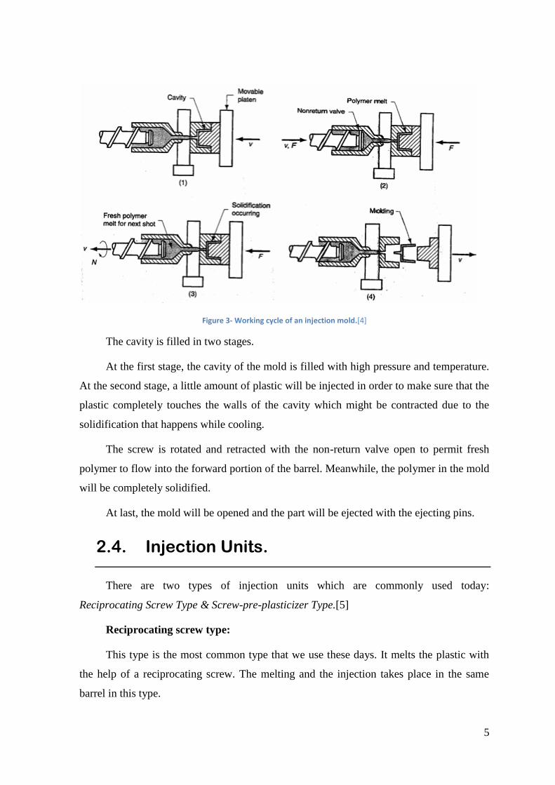
The working cycle proceeds in this way,
1. the mold is opened & the plastic that is required to be shaped into the
required product is melted and kept in the nozzle.
2. Then, the Mold is closed and clamped.
3. Now, a shot of melt(molten plastic), which has been heated to the right
temperature, is injected under high pressure into the mold cavity. The plastic
then fills the cavity of the mold and begins to solidify as it gets cooled when
it comes in contact with the cold surface of the mold.
5
Figure 3- Working cycle of an injection mold.[4]
The cavity is filled in two stages.
At the first stage, the cavity of the mold is filled with high pressure and temperature.
At the second stage, a little amount of plastic will be injected in order to make sure that the
plastic completely touches the walls of the cavity which might be contracted due to the
solidification that happens while cooling.
The screw is rotated and retracted with the non-return valve open to permit fresh
polymer to flow into the forward portion of the barrel. Meanwhile, the polymer in the mold
will be completely solidified.
At last, the mold will be opened and the part will be ejected with the ejecting pins.
2.4. Injection Units.
There are two types of injection units which are commonly used today:
Reciprocating Screw Type & Screw-pre-plasticizer Type.[5]
Reciprocating screw type:
This type is the most common type that we use these days. It melts the plastic with
the help of a reciprocating screw. The melting and the injection takes place in the same
barrel in this type.
6
Screw-pre-plasticizer type:
In this type, the plastic is kept in a separate container and the injection takes place in
another barrel for injecting a polymer. Because of which, this type is also called as two-
stage machine.
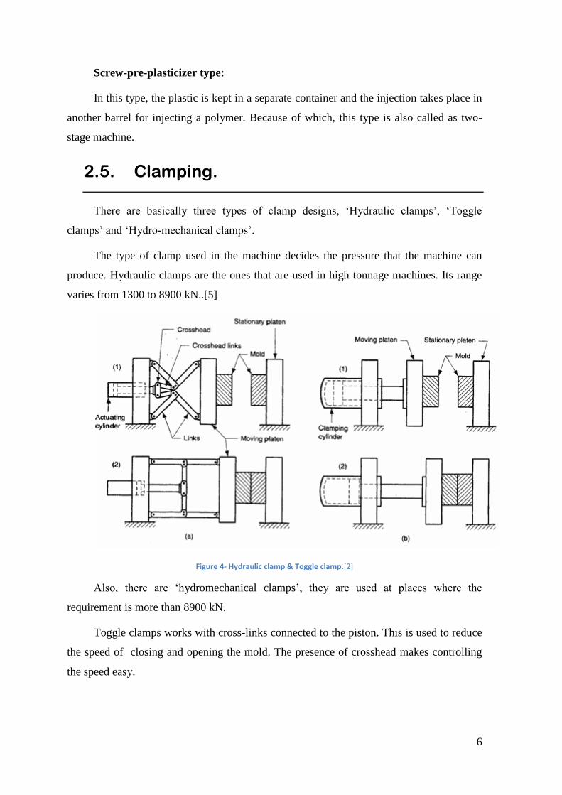
2.5. Clamping.
There are basically three types of clamp designs, ‘Hydraulic clamps’, ‘Toggle
clamps’ and ‘Hydro-mechanical clamps’.
The type of clamp used in the machine decides the pressure that the machine can
produce. Hydraulic clamps are the ones that are used in high tonnage machines. Its range
varies from 1300 to 8900 kN..[5]
Figure 4- Hydraulic clamp & Toggle clamp.[2]
Also, there are ‘hydromechanical clamps’, they are used at places where the
requirement is more than 8900 kN.
Toggle clamps works with cross-links connected to the piston. This is used to reduce
the speed of closing and opening the mold. The presence of crosshead makes controlling
the speed easy.
7
3. Mold Construction.
The mold has two major parts, the cavity and the core. The design of this cavity and
core is purely based on the design of the part that we want.[6]
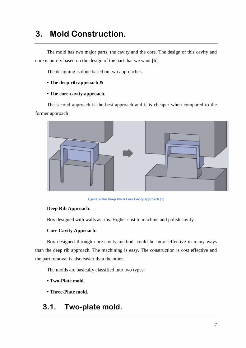
The designing is done based on two approaches.
• The deep rib approach &
• The core-cavity approach.
The second approach is the best approach and it is cheaper when compared to the
former approach
Figure 5-The Deep Rib & Core Cavity approach.[7]
Deep Rib Approach:
Box designed with walls as ribs. Higher cost to machine and polish cavity.
Core Cavity Approach:
Box designed through core-cavity method. could be more effective in many ways
than the deep rib approach. The machining is easy. The construction is cost effective and
the part removal is also easier than the other.
The molds are basically classified into two types:
• Two-Plate mold.
• Three-Plate mold.
3.1. Two-plate mold.
8
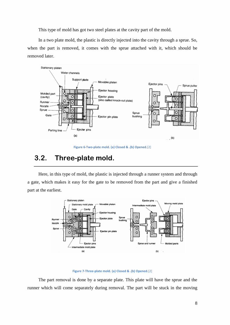
This type of mold has got two steel plates at the cavity part of the mold.
In a two plate mold, the plastic is directly injected into the cavity through a sprue. So,
when the part is removed, it comes with the sprue attached with it, which should be
removed later.
Figure 6-Two-plate mold. (a) Closed & .(b) Opened.[2]
3.2. Three-plate mold.
Here, in this type of mold, the plastic is injected through a runner system and through
a gate, which makes it easy for the gate to be removed from the part and give a finished
part at the earliest.
Figure 7-Three-plate mold. (a) Closed & .(b) Opened.[2]
The part removal is done by a separate plate. This plate will have the sprue and the
runner which will come separately during removal. The part will be stuck in the moving
9
half of the mold due to the shrinkage that occurs while cooling and therefore, the part will
be held there. On the other side, the separate plate removes the sprue and runner.
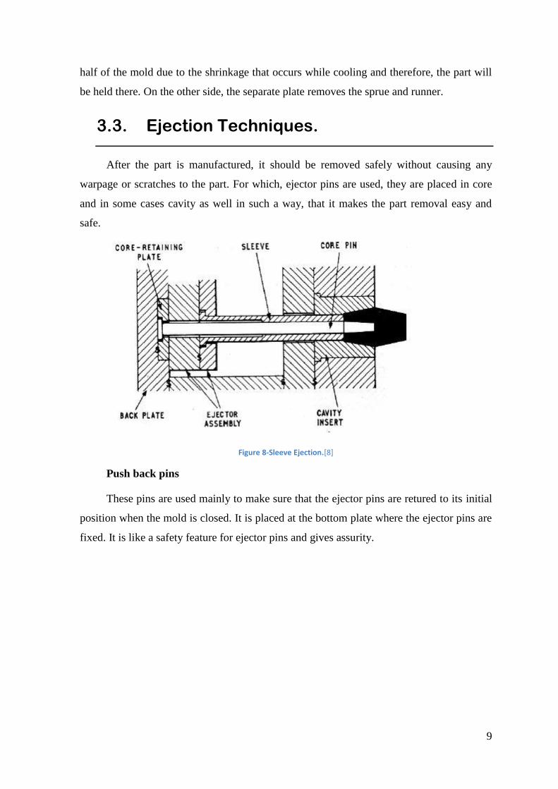
3.3. Ejection Techniques.
After the part is manufactured, it should be removed safely without causing any
warpage or scratches to the part. For which, ejector pins are used, they are placed in core
and in some cases cavity as well in such a way, that it makes the part removal easy and
safe.
Figure 8-Sleeve Ejection.[8]
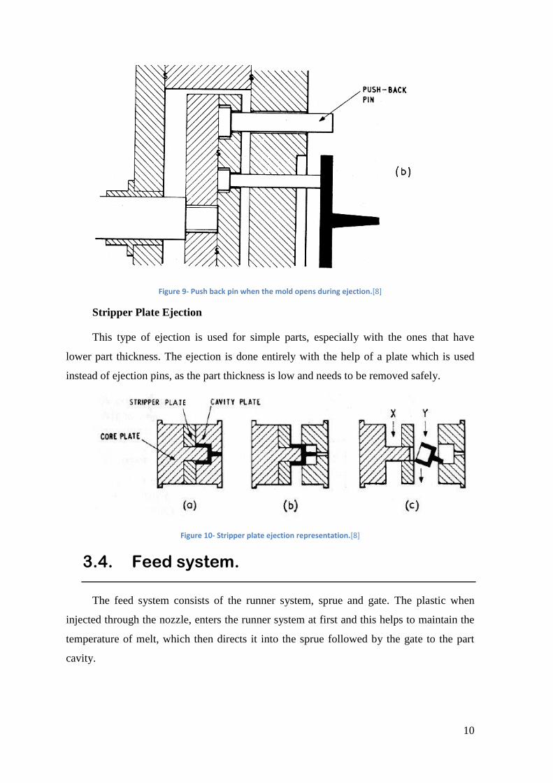
Push back pins
These pins are used mainly to make sure that the ejector pins are retured to its initial
position when the mold is closed. It is placed at the bottom plate where the ejector pins are
fixed. It is like a safety feature for ejector pins and gives assurity.
10
Figure 9- Push back pin when the mold opens during ejection.[8]
Stripper Plate Ejection
This type of ejection is used for simple parts, especially with the ones that have
lower part thickness. The ejection is done entirely with the help of a plate which is used
instead of ejection pins, as the part thickness is low and needs to be removed safely.
Figure 10- Stripper plate ejection representation.[8]
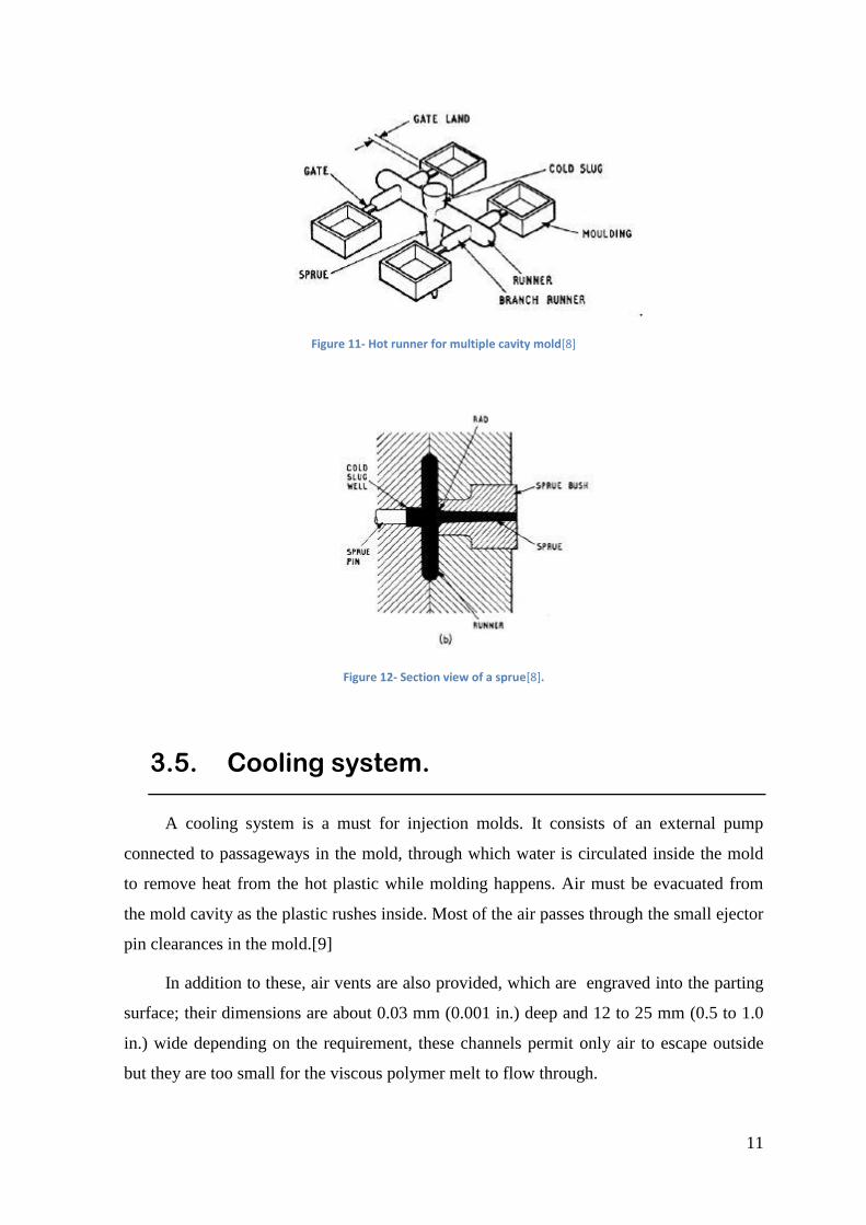
3.4. Feed system.
The feed system consists of the runner system, sprue and gate. The plastic when
injected through the nozzle, enters the runner system at first and this helps to maintain the
temperature of melt, which then directs it into the sprue followed by the gate to the part
cavity.
11
Figure 11- Hot runner for multiple cavity mold[8]
Figure 12- Section view of a sprue[8].
3.5. Cooling system.
A cooling system is a must for injection molds. It consists of an external pump
connected to passageways in the mold, through which water is circulated inside the mold
to remove heat from the hot plastic while molding happens. Air must be evacuated from
the mold cavity as the plastic rushes inside. Most of the air passes through the small ejector
pin clearances in the mold.[9]
In addition to these, air vents are also provided, which are engraved into the parting
surface; their dimensions are about 0.03 mm (0.001 in.) deep and 12 to 25 mm (0.5 to 1.0
in.) wide depending on the requirement, these channels permit only air to escape outside
but they are too small for the viscous polymer melt to flow through.
12
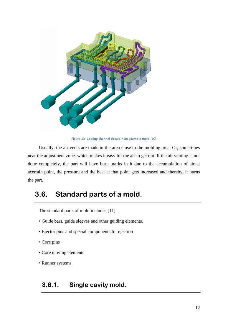
Figure 13- Cooling channel circuit in an example mold.[10]
Usually, the air vents are made in the area close to the molding area. Or, sometimes
near the adjustment zone. which makes it easy for the air to get out. If the air venting is not
done completely, the part will have burn marks in it due to the accumulation of air at
acertain point, the pressure and the heat at that point gets increased and thereby, it burns
the part.
3.6. Standard parts of a mold.
The standard parts of mold includes,[11]
• Guide bars, guide sleeves and other guiding elements.
• Ejector pins and special components for ejection
• Core pins
• Core moving elements
• Runner systems
3.6.1. Single cavity mold.
13
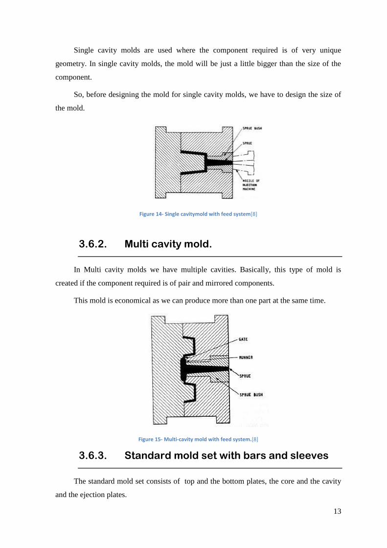
Single cavity molds are used where the component required is of very unique
geometry. In single cavity molds, the mold will be just a little bigger than the size of the
component.
So, before designing the mold for single cavity molds, we have to design the size of
the mold.
Figure 14- Single cavitymold with feed system[8]
3.6.2. Multi cavity mold.
In Multi cavity molds we have multiple cavities. Basically, this type of mold is
created if the component required is of pair and mirrored components.
This mold is economical as we can produce more than one part at the same time.
Figure 15- Multi-cavity mold with feed system.[8]
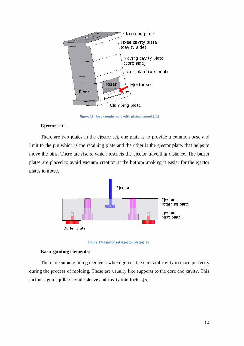
3.6.3. Standard mold set with bars and sleeves
The standard mold set consists of top and the bottom plates, the core and the cavity
and the ejection plates.
14
Figure 16- An example mold with plates named.[11]
Ejector set:
There are two plates in the ejector set, one plate is to provide a common base and
limit to the pin which is the retaining plate and the other is the ejector plate, that helps to
move the pins. There are risers, which restricts the ejector travelling distance. The buffer
plates are placed to avoid vacuum creation at the bottom ,making it easier for the ejector
plates to move.
Figure 17- Ejector set (Ejector plates)[11]
Basic guiding elements:
There are some guiding elements which guides the core and cavity to close perfectly
during the process of molding. These are usually like supports to the core and cavity. This
includes guide pillars, guide sleeve and cavity interlocks..[5]
15
Figure 18- Tapered interlocks and Straight side interlocks.[11]
3.6.4. Ejector pins and special components for
ejection.
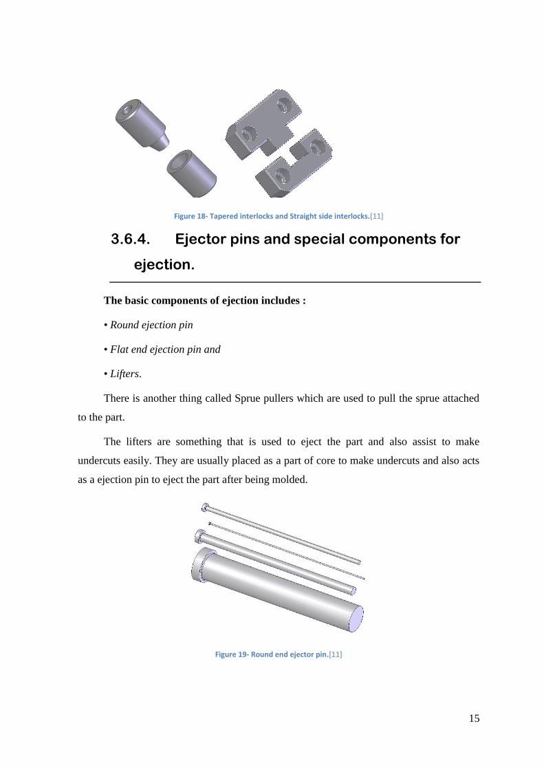
The basic components of ejection includes :
• Round ejection pin
• Flat end ejection pin and
• Lifters.
There is another thing called Sprue pullers which are used to pull the sprue attached
to the part.
The lifters are something that is used to eject the part and also assist to make
undercuts easily. They are usually placed as a part of core to make undercuts and also acts
as a ejection pin to eject the part after being molded.
Figure 19- Round end ejector pin.[11]
16
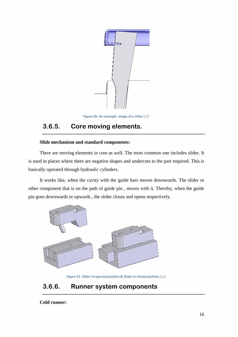
Figure 20- An example image of a Lifter [11]
3.6.5. Core moving elements.
Slide mechanism and standard components:
There are moving elements in core as well. The most common one includes slider. It
is used in places where there are negative shapes and undercuts to the part required. This is
basically operated through hydraulic cylinders.
It works like, when the cavity with the guide bars moves downwards. The slider or
other component that is on the path of guide pin , moves with it. Thereby, when the guide
pin goes downwards or upwards , the slider closes and opens respectively.
Figure 21- Slider in opened position & Slider in closed position.[11]
3.6.6. Runner system components
Cold runner:
17
The need of a runner system is to create the melted plastic a specified path from the
nozzle to the mould cavitiy. In cold runner system.the [plastic solidifies inside it and
therefore, it is removed along with the part and has to be detached separately..
Hot runner:
The sprue and runner in the common two-plate or three-plate mold are mostly a
waste material. In many cases they can be grounded and reused; however, in some
instances the product must be made of “virgin” plastic (that which has not been previously
molded). In such case, The hot-runner mold eliminates the solidification of the sprue and
runner by locating heaters around the corresponding runner channels. While the plastic in
the mold cavity solidifies, the material in the sprue and runner channels remains molten,
ready to be injected into the cavity in the next cycle.
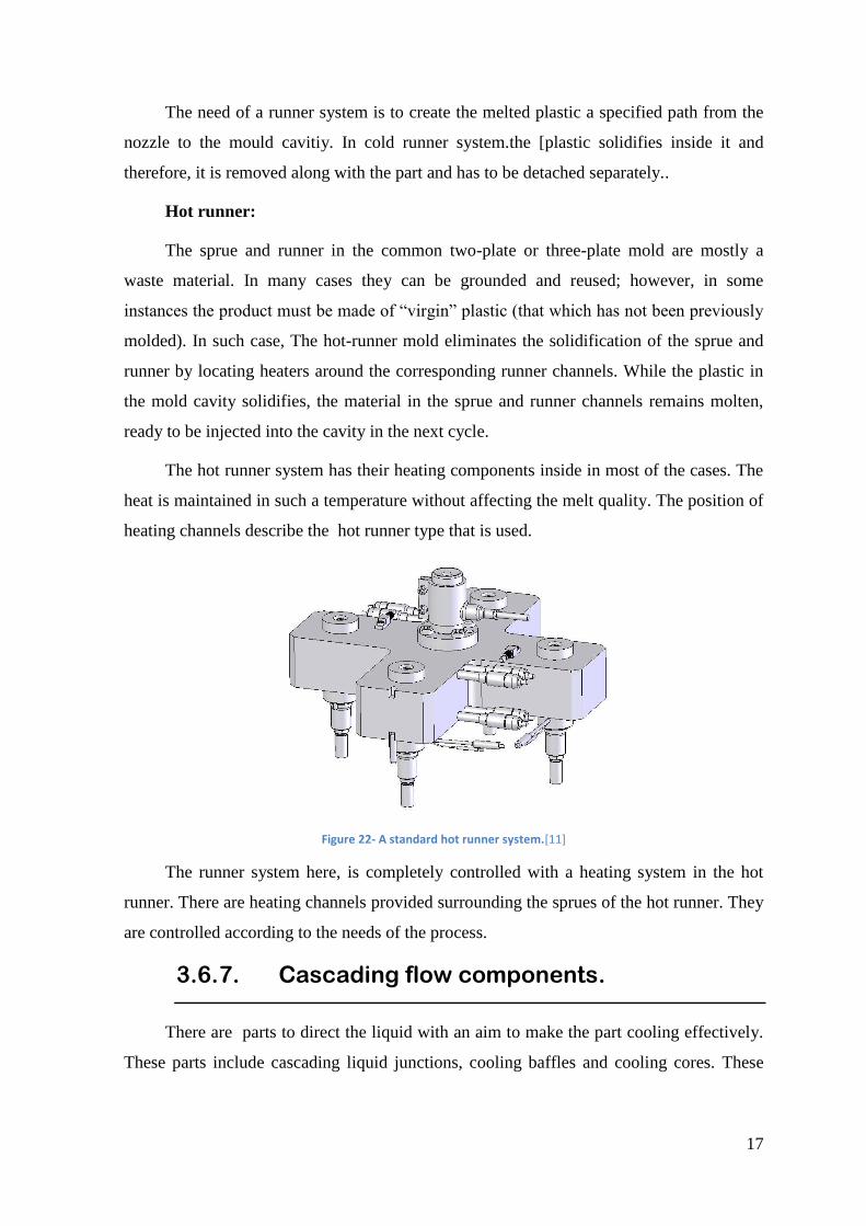
The hot runner system has their heating components inside in most of the cases. The
heat is maintained in such a temperature without affecting the melt quality. The position of
heating channels describe the hot runner type that is used.
Figure 22- A standard hot runner system.[11]
The runner system here, is completely controlled with a heating system in the hot
runner. There are heating channels provided surrounding the sprues of the hot runner. They
are controlled according to the needs of the process.
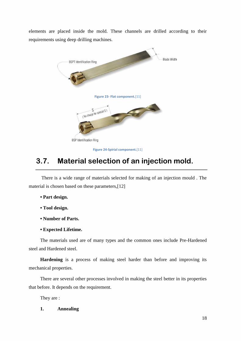
3.6.7. Cascading flow components.
There are parts to direct the liquid with an aim to make the part cooling effectively.
These parts include cascading liquid junctions, cooling baffles and cooling cores. These
18
elements are placed inside the mold. These channels are drilled according to their
requirements using deep drilling machines.
Figure 23- Flat component.[11]
Figure 24-Spirial component.[11]
3.7. Material selection of an injection mold.
There is a wide range of materials selected for making of an injection mould . The
material is chosen based on these parameters,[12]
• Part design.
• Tool design.
• Number of Parts.
• Expected Lifetime.
The materials used are of many types and the common ones include Pre-Hardened
steel and Hardened steel.
Hardening is a process of making steel harder than before and improving its
mechanical properties.
There are several other processes involved in making the steel better in its properties
that before. It depends on the requirement.
They are :
1. Annealing
19
2. Normalizing
3. Hardening &
4. Tempering.
1.Annealing:
Heating the steel to a defined temperature and cooling it in conditioned atmosphere
like in furnace. properties like ductility, softness, toughness, fine grain size and
machinability. This reduces the hardness.
2.Normalizing:
Heating the steel to above austenitic range or critical temperature and holding it for a
particular period of time to let the transformation occur and after air cooled. It makes
uniform carbide size, which enables heat treatment process later to produce more uniform
final product.
3. Hardening:
After heating the metal, the material is cooled in a medium, i.e having drastic change
in temperature. Here during this process, we are not allowing the grains to grow after
nucleation resulting in very fine grains. This fast cooling is called quenching.
Quenching can be done with different medium, such as water quench, brine solution
quench, oil quench. Quench severity changes with change in medium.
4.Tempering:
Tempering is a process of heat treating, which is used to increase the toughness of
iron-based alloys. Tempering is usually performed after hardening, to reduce some of the
excess hardness, and is done by heating the metal to some temperature below the critical
point for a certain period of time, then allowing it to cool in still air. increase ductility and
softness, cutting properties and magnetic properties.
Commonly used material includes H-13 ,P-20 ,S50C ,718 steel. [13]
Material Applications
H-13 steel Post hardened steel for high volume molds.
Stainless Steel Post hardened stainless steel for high volume molds
20
P-20 Steel Pre hardened tool steel for middle volume molds.
Nak 80 Steel Pre hardened tool steel for middle volume molds
S50c Steel Tool steel for low volume molds
718 Steel Tool steel for low volume molds.
Table 1- Commonly used material for mold andits applications.[14]
Here, the most commonly seen material is P20. Chromium and nickel are the main
alloying elements found in group P steels. P20 tool steels are nitrided or carburized. These
steels are capable of being machined into complex and large dies and molds. P20 steels are
mostly used in the carburized condition. The presence of chromium and nickel enhances
the toughness and hardness of P20 steels.
Substance Content
C 0.28-0.40
Mg 0.60-1.00
Si 0.20-0.80
Cr 1.40-2.00
Mo 0.30-0.55
Cu 0.25
P 0.03
S 0.03
Table 2- Chemical composition of P20 steel.[14]
P20 Tool Steel Equivalent Steel Grades:
Country Standard Grades
USA ASTM A681 P 20
Germany ( Most of Europe) DIN EN ISO 4957 1.2311
China GB/T 1299 3 Cr Mo
Table 3- P20 Tool Steel Equivalent Steel Grades[14]
.Here, in Portugal we use `DIN EN ISO 4957` standard.
Commonly used steel :
21
The company usually buy steel plates from ``HASCO``.
The HASCO has a Catalogue in three categories. `K` , `P` and `Z`
Where K – Large Steel plates like Top plate, Bottom plate and Intermediate Plates.
P – This consists of the steel inserts , Round parts, Machined plates.
Z – This set consists of Guide Pins, Ejection Pins , Measurement systems
Temperature system , ..etc
PLATE or PART NUMBER. MATERIALS USED.
1 and 9 1.1730 , 1.2083 ,1.2085 ,1.2311 ,1.2312
2 ,3 and 4 1.1730 ,1.203 ,1.2085 ,1.2162 ,1.2311 ,1.2312
,1.2767
5 1.1730 ,1.203 ,1.2085 ,1.2311 ,1.2312 ,1.2343
,1.2436
6 1.1730 ,1.2085 ,1.2162 ,1.2311 ,1.2343 ,1.2436
7 and 8 1.1730 ,1.2085
Ejector Pin (Round ) 1.2516
Ejector Pin (Flat) 1.2343
Ejector Sleeve 1.2343
Table 4- Mold plate numbering and the common materials it is made of.
These are the materials that is used for commonly for the manufacturing of an
injection mould.
Material Heat treatment Properties
1.1730 Soft annealing: • Temperature 680 -.710°C
•Furnace cooled
•Maximum Hardness is207 HB
Stress relief annealing: • Temperature 600 - 650°C
•Furnace cooled
Hardening •Temperature 800 -850°C
•Water cooled
1.2311 Soft annealing: •Temperature – 710-740°C
•Furnace cooled
•Maximum Hardness is235 HB
22
Stress relief annealing : •Temperature – 500-550°C
•Furnace cooled
Hardening : •Temperature – 830 -870°C
•Oil or Hot bath cooling – 180-220°C
1.2312 Soft annealing : •Temperature – 710-740°C
•Furnace cooled
•MaximumHardness is 235 HB
Stress relief annealing : •Temperature – 500-550°C
•Furnace cooling
Hardening: •Temperature – 830 -870°C
•Oil or Hot bath cooling –180 -220°C
Table 5-Commonly used materials.[15] [16]
3.8. Defects in injection mold
This section comprises of an important aspect that makes the injection molded part,
more better and reliable. As the part comes out from the machine at the beginning, there
will be definitely some defects, where some are ignorable and some should be sorted out
depending upon the customer requirement. The major defects that could be seen and their
possible remedies is prescribed below.
Table 6- Common Defects in injection molding.
DEFECTS BRIEF.
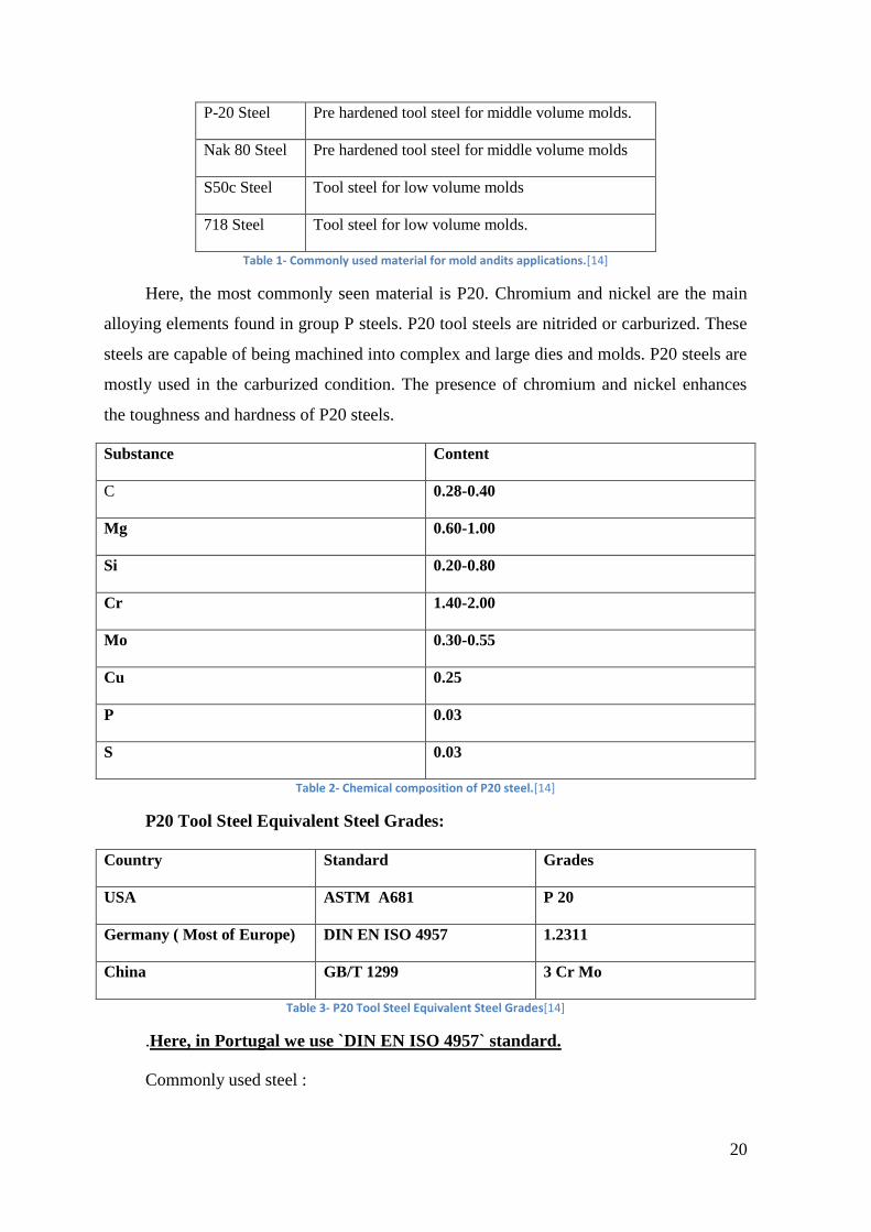
SINK MARKS:
Figure 25- Sink marks indicated in a part.[17]
The cooling of an injected part is
very important during the process. These
sink marks occurs due to uneven cooling
of the part, which happens often at thicker
areas of the part. The inner area gets
cooled first thereby starts shrinking, which
appears to be a inner bulge.
Uniform cooling and increasing
holding time can solve this problem.
SHORT SHOT: The melt volume to be injected per
shot should be slightly more than that of
the volume of cavity so that the part would
23
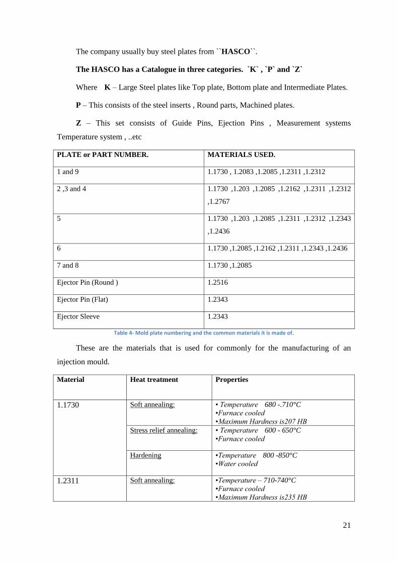
Figure 26- Short shot indicating incomplete component.[17]
be complete. It also occurs, if the melt
viscosity is more and not enough heating is
provided.
Increasing mold & melt temperature
and melt pressure increasing during
injection will reduce this issue.
WARPAGE:
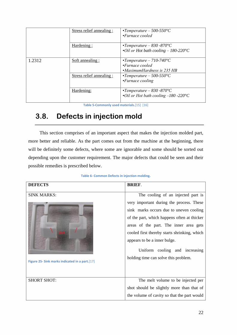
Figure 27- An image indicating the difference between the required part and the part that has warpage.[18]
Lengthy parts would oftern experience
warpage at the ends. Parts that are not long
will also have warpage in it but it is
solvable.
Proving supports in weaker part sections in
the form of bosses and gussets tend to
decrease warpage to a greater extent.
BURN MARKS:
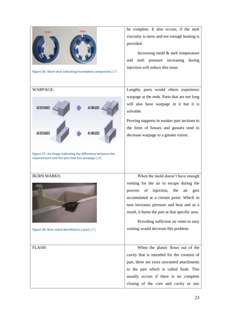
Figure 28- Burn mark identified in a part.[17]
When the mold doesn’t have enough
venting for the air to escape during the
process of injection, the air gets
accumulated at a certain point. Which in
turn increases pressure and heat and as a
result, it burns the part at that specific area.
Providing sufficient air vents to easy
venting would decrease this problem.
FLASH: When the plastic flows out of the
cavity that is intended for the creation of
part, there are extra unwanted attachments
to the part which is called flash. This
usually occurs if there is no complete
closing of the core and cavity or any
24
Figure 29- a part with flashes in it.[17]
damage in the adjustment zone of the
mold.
By reducing the injection pressure
and melt temperature, flashes can be
avoided.
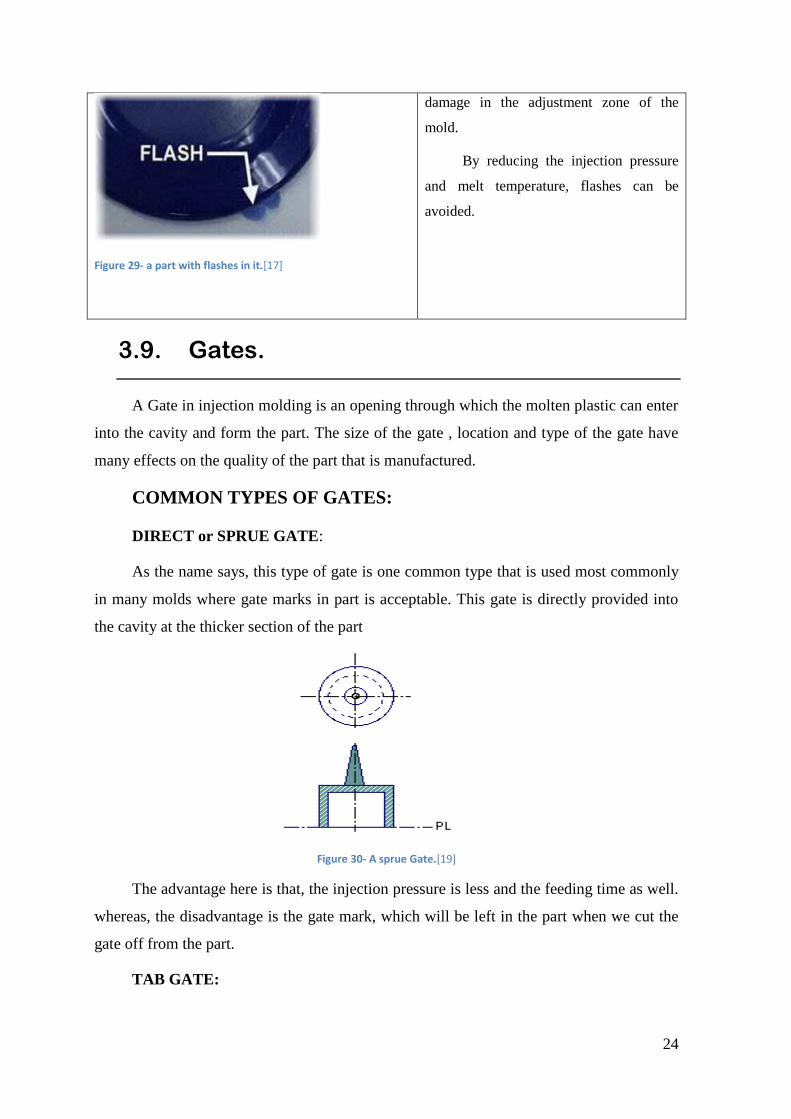
3.9. Gates.
A Gate in injection molding is an opening through which the molten plastic can enter
into the cavity and form the part. The size of the gate , location and type of the gate have
many effects on the quality of the part that is manufactured.
COMMON TYPES OF GATES:
DIRECT or SPRUE GATE:
As the name says, this type of gate is one common type that is used most commonly
in many molds where gate marks in part is acceptable. This gate is directly provided into
the cavity at the thicker section of the part
Figure 30- A sprue Gate.[19]
The advantage here is that, the injection pressure is less and the feeding time as well.
whereas, the disadvantage is the gate mark, which will be left in the part when we cut the
gate off from the part.
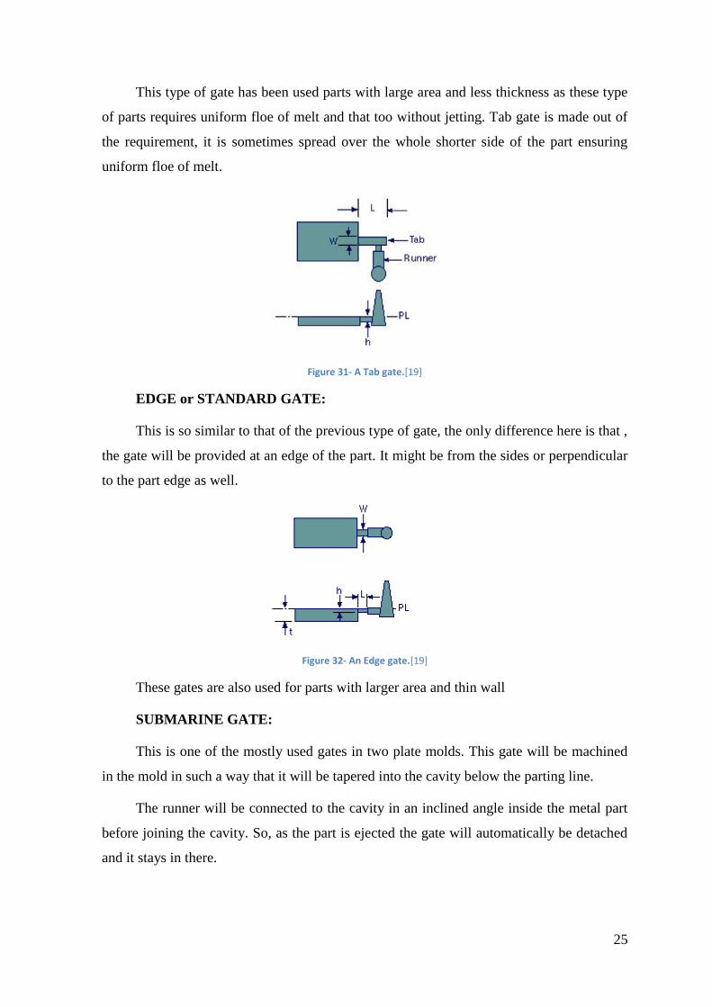
TAB GATE:
25
This type of gate has been used parts with large area and less thickness as these type
of parts requires uniform floe of melt and that too without jetting. Tab gate is made out of
the requirement, it is sometimes spread over the whole shorter side of the part ensuring
uniform floe of melt.
Figure 31- A Tab gate.[19]
EDGE or STANDARD GATE:
This is so similar to that of the previous type of gate, the only difference here is that ,
the gate will be provided at an edge of the part. It might be from the sides or perpendicular
to the part edge as well.
Figure 32- An Edge gate.[19]
These gates are also used for parts with larger area and thin wall
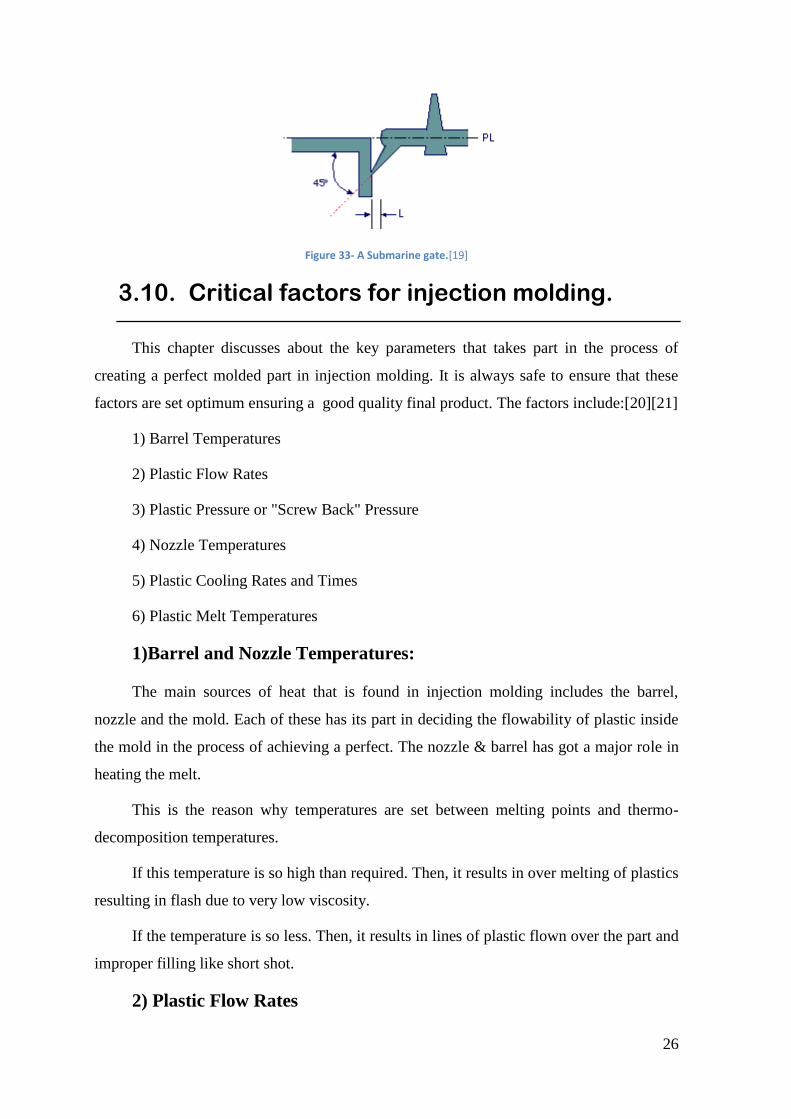
SUBMARINE GATE:
This is one of the mostly used gates in two plate molds. This gate will be machined
in the mold in such a way that it will be tapered into the cavity below the parting line.
The runner will be connected to the cavity in an inclined angle inside the metal part
before joining the cavity. So, as the part is ejected the gate will automatically be detached
and it stays in there.
26
Figure 33- A Submarine gate.[19]
3.10. Critical factors for injection molding.
This chapter discusses about the key parameters that takes part in the process of
creating a perfect molded part in injection molding. It is always safe to ensure that these
factors are set optimum ensuring a good quality final product. The factors include:[20][21]
1) Barrel Temperatures
2) Plastic Flow Rates
3) Plastic Pressure or "Screw Back" Pressure
4) Nozzle Temperatures
5) Plastic Cooling Rates and Times
6) Plastic Melt Temperatures
1)Barrel and Nozzle Temperatures:
The main sources of heat that is found in injection molding includes the barrel,
nozzle and the mold. Each of these has its part in deciding the flowability of plastic inside
the mold in the process of achieving a perfect. The nozzle & barrel has got a major role in
heating the melt.
This is the reason why temperatures are set between melting points and thermo-
decomposition temperatures.
If this temperature is so high than required. Then, it results in over melting of plastics
resulting in flash due to very low viscosity.
If the temperature is so less. Then, it results in lines of plastic flown over the part and
improper filling like short shot.
2) Plastic Flow Rates
27
The flow rates for plastic injection represents the ease of plastic melt to flow inside
the mold to fill it.
The flow rate determines the viscosity of the plastic by the time it flows inside the
mold cavity. In such a case, if the holding pressures is too high, it creates flash and
overflow of melt and if the pressure is too low, the melt flow doesn’t exert pressure to vent
air outside the cavity resulting in void formation.
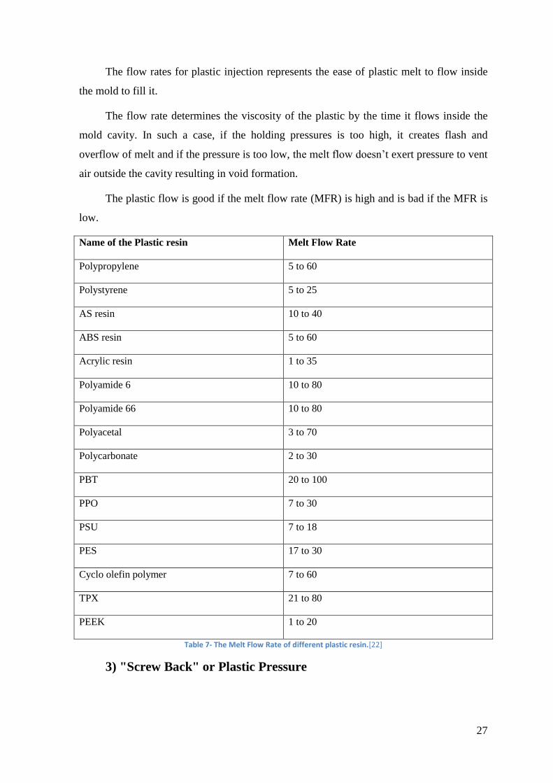
The plastic flow is good if the melt flow rate (MFR) is high and is bad if the MFR is
low.
Name of the Plastic resin Melt Flow Rate
Polypropylene 5 to 60
Polystyrene 5 to 25
AS resin 10 to 40
ABS resin 5 to 60
Acrylic resin 1 to 35
Polyamide 6 10 to 80
Polyamide 66 10 to 80
Polyacetal 3 to 70
Polycarbonate 2 to 30
PBT 20 to 100
PPO 7 to 30
PSU 7 to 18
PES 17 to 30
Cyclo olefin polymer 7 to 60
TPX 21 to 80
PEEK 1 to 20
Table 7- The Melt Flow Rate of different plastic resin.[22]
3) "Screw Back" or Plastic Pressure
28
Screw pressure is nothing but the pressure created due to the feeding screw. It is
created between the screw and the plastic when the cavity is filled and the pressure is
exerted back onto the screw by the plastic. It is normally controlled by valve.
If the injection pressure is high, it creates problems like overflowing and flash and
when the pressure is too low, voids might be formed.
4) Nozzle Temperatures:
The temperature of the nozzle should be lower than that of the temperature of the
barrel. By this, the plastic inside the nozzle remains in a good quality. If not, the plastic
gets decomposed.
Too high temperatures, makes some plastic to flow outside even if the nozzle is
closed and if there is not enough heat, melt solidifies and blocks the nozzle and resulting in
bad quality parts produced.
5) Melt and Mold cooling:
The range of cooling usually depends on the temperature of melt and the mold.
Temperature of the mold depends on the temperature that the client recommended and the
temperature that has to be used for the material used in the mold.
The dependency of cooling and timing is that, it depends largely on the client’s
expectation. Also , on the time required to produce perfect shaped part and perfect finish
6) Melt Temperatures:
To attain the perfect melt temperature is one important factor to be considered.
Because, the melt to be injected inside the cavity should be at the perfect temperature to
make it completely flow inside the mold and make the perfect part. It could be achieved by
adjusting the temperatures of nozzle, barrel and the mold.
29
4. Activities developed
I did my internship at Moldetipo, a leading molding company in Portugal. They
manufacture excellent molds and provide it to their customers.
Here in this section, the process cycle of an injection mold which is studied
practically during the period of internship is about to be discussed in detail
Each section will be elaborated in a sequence how an injection mold is made. The
operations that took place at each section with the observations are described
4.1. CNC
At first when I started my internship, I was in the CNC section in the beginning. The
CNC section is where, the mold starts getting manufactured. The major carving of the
mold cavity and the core is completely done in the CNC.
Let’s first talk about the basics of what a CNC machine is and the commonly seen
types.
CNC (Computer Numerical Control) is a machining is a type of machine that is most
commonly used in molding industry to machine molds. The CNC machines are of many
types and depending upon our requirement, the type is chosen.
The most common type of CNC machine is 3-axis machine. Which has movement or
translation in X,Y and Z directions.
30
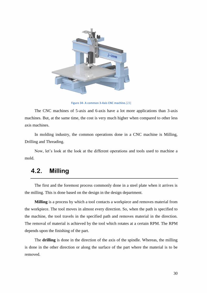
Figure 34- A common 3-Axis CNC machine.[23]
The CNC machines of 5-axis and 6-axis have a lot more applications than 3-axis
machines. But, at the same time, the cost is very much higher when compared to other less
axis machines.
In molding industry, the common operations done in a CNC machine is Milling,
Drilling and Threading.
Now, let’s look at the look at the different operations and tools used to machine a
mold.
4.2. Milling
The first and the foremost process commonly done in a steel plate when it arrives is
the milling. This is done based on the design in the design department.
Milling is a process by which a tool contacts a workpiece and removes material from
the workpiece. The tool moves in almost every direction. So, when the path is specified to
the machine, the tool travels in the specified path and removes material in the direction.
The removal of material is achieved by the tool which rotates at a certain RPM. The RPM
depends upon the finishing of the part.
The drilling is done in the direction of the axis of the spindle. Whereas, the milling
is done in the other direction or along the surface of the part where the material is to be
removed.
31
Milling produces 3-dimensional shapes with a rotating multi-edge cutting tool. The
cutting tool can be programmed to move against a fixed workpiece in almost any direction.
Milling tools remove material by their movement in the machine and from their shape.
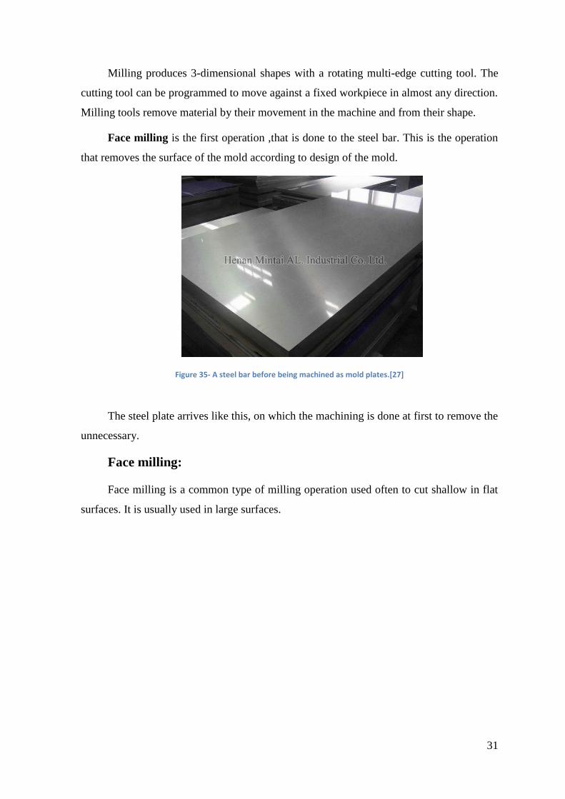
Face milling is the first operation ,that is done to the steel bar. This is the operation
that removes the surface of the mold according to design of the mold.
Figure 35- A steel bar before being machined as mold plates.[27]
The steel plate arrives like this, on which the machining is done at first to remove the
unnecessary.
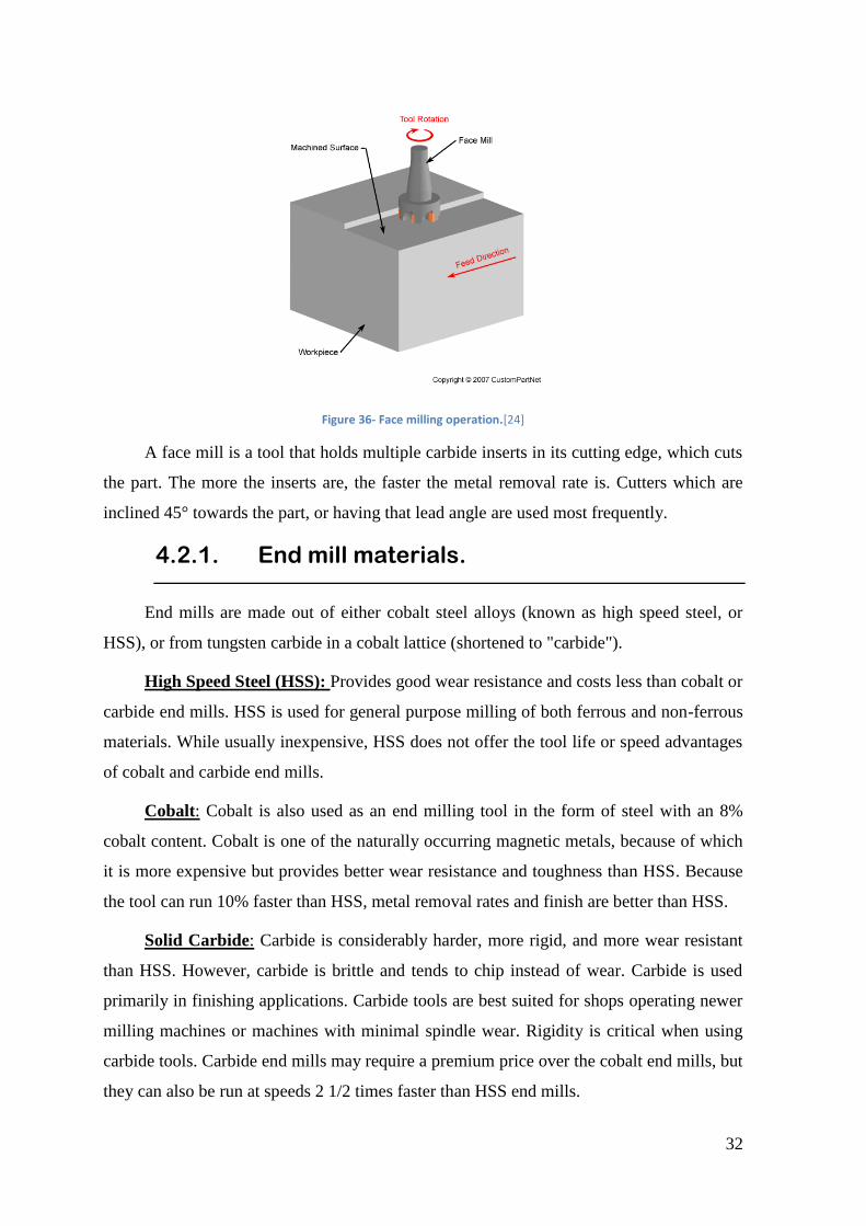
Face milling:
Face milling is a common type of milling operation used often to cut shallow in flat
surfaces. It is usually used in large surfaces.
32
Figure 36- Face milling operation.[24]
A face mill is a tool that holds multiple carbide inserts in its cutting edge, which cuts
the part. The more the inserts are, the faster the metal removal rate is. Cutters which are
inclined 45° towards the part, or having that lead angle are used most frequently.
4.2.1. End mill materials.
End mills are made out of either cobalt steel alloys (known as high speed steel, or
HSS), or from tungsten carbide in a cobalt lattice (shortened to "carbide").
High Speed Steel (HSS): Provides good wear resistance and costs less than cobalt or
carbide end mills. HSS is used for general purpose milling of both ferrous and non-ferrous
materials. While usually inexpensive, HSS does not offer the tool life or speed advantages
of cobalt and carbide end mills.
Cobalt: Cobalt is also used as an end milling tool in the form of steel with an 8%
cobalt content. Cobalt is one of the naturally occurring magnetic metals, because of which
it is more expensive but provides better wear resistance and toughness than HSS. Because
the tool can run 10% faster than HSS, metal removal rates and finish are better than HSS.
Solid Carbide: Carbide is considerably harder, more rigid, and more wear resistant
than HSS. However, carbide is brittle and tends to chip instead of wear. Carbide is used
primarily in finishing applications. Carbide tools are best suited for shops operating newer
milling machines or machines with minimal spindle wear. Rigidity is critical when using
carbide tools. Carbide end mills may require a premium price over the cobalt end mills, but
they can also be run at speeds 2 1/2 times faster than HSS end mills.
33
The choice of tool material depends on the material to be cut as well as on the
maximum spindle speed of the machine. Smaller milling machines may not be capable of
reaching the spindle speeds recommended for carbide end mills.
4.2.2. Observations
The major operations and processes of a CNC machine has been understood at the
period of being there in the CNC department. The major issues and their remedies which
contributes mostly to the betterment of the mold is analysed to an extent in the internship.
CNC Program
The CNC programs were basically controlled by a numerical controller. The
company where the internship is done uses numerical controllers provided by FANUC for
its CNC machines.
At first, the program is constructed in a simulation software to check the result of it.
and if everything seems okay, then it is fed into the CNC machine. After which follows the
program and makes the machining.
The main considerations that needs to be addressed are, machining a perfect 90°
surface at the bottom of two planes intersecting each other is a task to be accomplished. To
machine a perfect 90° surface in CNC is really a difficult task and also, if we have to
machine a part like that, then it’s not going to allow the other part to go inside and come
out easily. There will be complete friction between the two surfaces and thereby creates
wear and material removal.
The adjustment zone and molding zone surfaces are of different finish from the
remaining area’s finish. The reason being, it is the place where the plastic is molded. Since,
the plastic should spread around the complete cavity without any lag. It is so important to
machine the molding zone to machine differently in a finely polished surface with friction
for the part to stick.
Drilling perfect water circuit for cooling is another important aspect to be considered.
Which is done by deep drilling machines. These machines have lengthy drill pits, with
which they drill the holes for water circuits.
4.3. Production/Bancada.
34
The mold after getting machined in CNC then goes to the production bench. Where it
gets adjusted and then all the inserts that need to be put in there are inserted.
Operations performed at this stage:
• The water circuit machined is checked with water pump. And if there is any
leakage are merge between two different lines .
• The lines are connected with its respected connectors.
• Pressure plug is used to block the line at a certain point.
• Baffles are used to divert the coolant in a specific direction to prolong the period of
coolant to flow in the molding area cooling the plastic.
• The adjustments at the molding zone are done. These includes, making sharp edges
blunt and inserting inserts.
4.4. Erosion
The mold after finishing its initial role in production, it is then sent to erosion. This is
a department where, the mold will be machined in such a way that, the metal from the
mold is met with high voltage electric sparks from a machine through an electrode, which
then removes the material though erosion.
The machine used for is called EDM ( Electric Discharge Machining ).
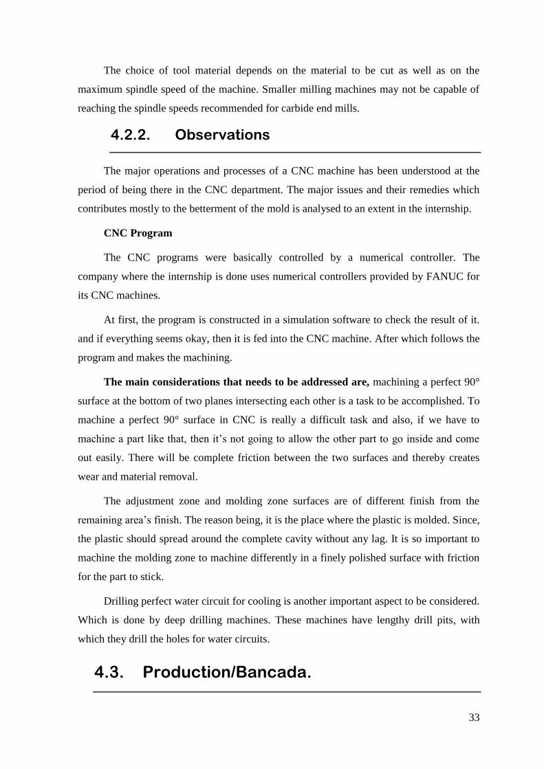
Electric Discharge Machining:
The working of the machine begins when the electrode comes closer to the
workpiece, an electric spark is produced which melts the material. This spark is created by
high voltage and it is of very high temperature, about 8000 to 12500 degree Celsius.
Figure 37- A schematic representation of EDM process .[25]
35
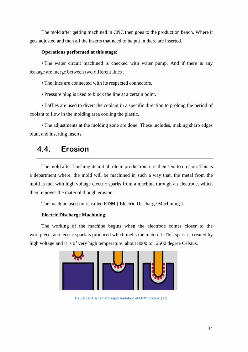
So, when this spark melts the metal and erodes it, this gets settled down at the bottom
of the machining space. The workpiece is immersed in a dielectric fluid and so, the entire
process happens immersed in the dielectric fluid
Figure 38- The overall setup of Electro Discharge Machining.[26]
The dielectric also acts as a coolant and erodes the metal away as well. The spark
gap, which is also called the “discharge gap” is the distance between the electrode and the
graphite. The discharge gap varies from 0.005mm to 1.0mm. The more the gap, the bigger
the spark is and vice versa.
The sparks are produced about 1000 - 100,000 times per second between the
electrode and the metal by which, it carves a shape of the electrode to the metal. The
machining takes place till the required shape and finishing is achieved.
The electrode is commonly made of graphite or copper, depending upon the
workpiece and the operation to be done.
If the electrode accidently touches the workpiece, the spark stops and therefore ,
there won’t be any erosion. There is a discharge servo, which makes the movement of the
electrode up and down. So, it takes the electrode up when this kind of things happen.
Wire Cutting EDM.
This is the same mechanism which uses a wire to cut the material. The wire EDM is
used in places where contour or tapered cuts are needed. Such cuts are not easy or in some
cases not possible to cut in CNC. So, wire EDM is used to cut such difficult shapes.
36
Figure 39- A working Wire-cutting EDM machine.[27]
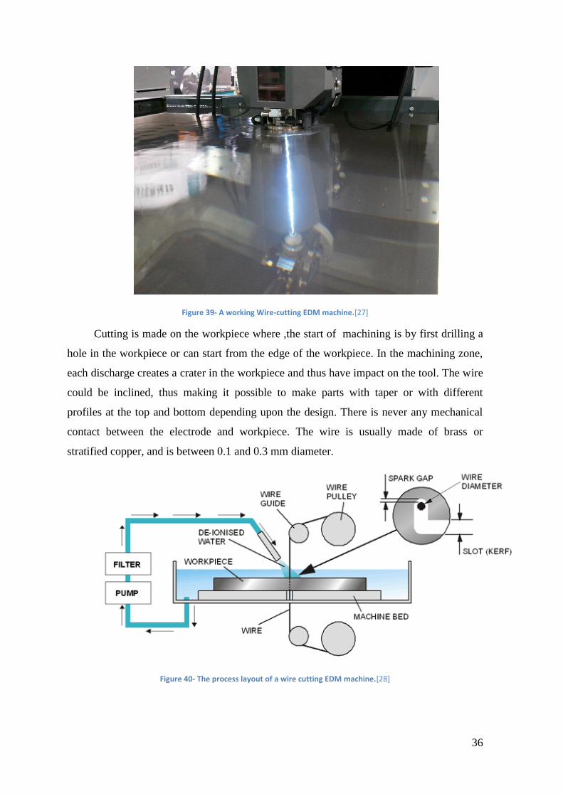
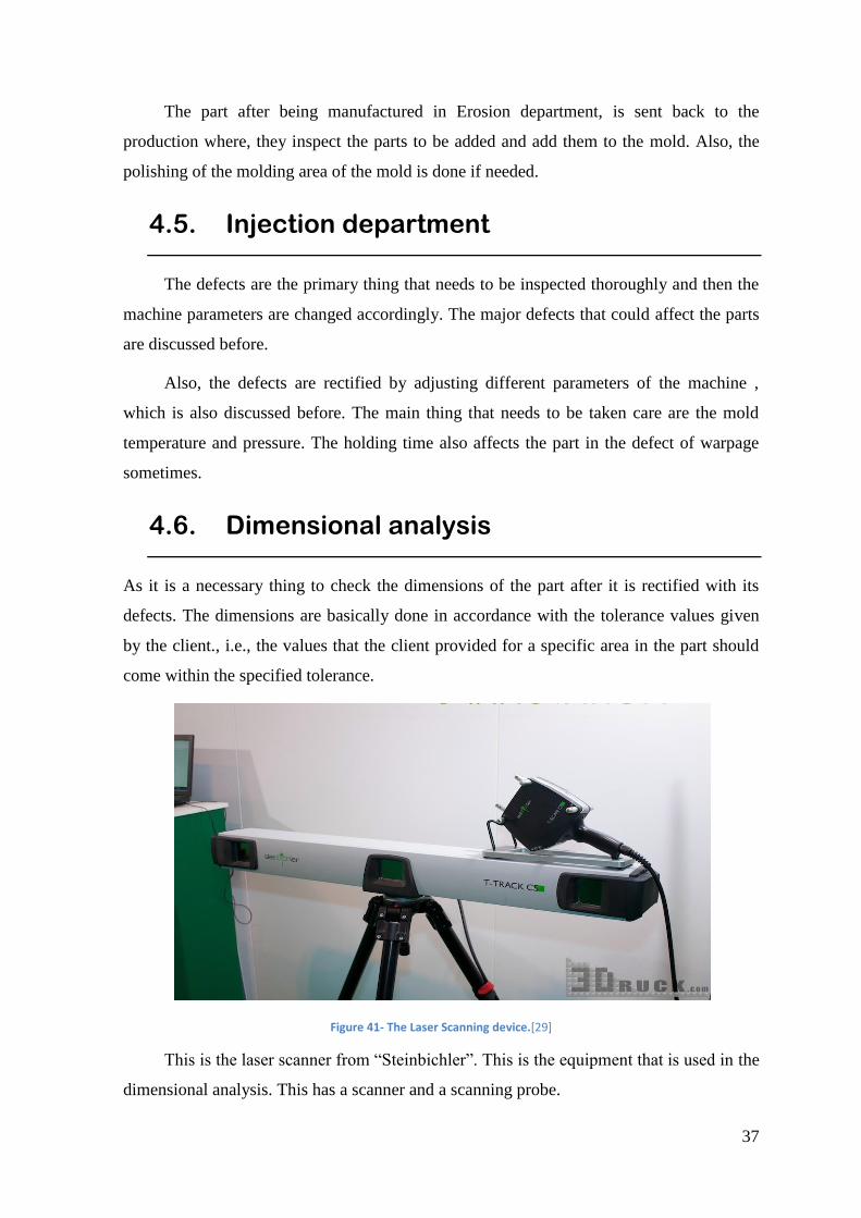
Cutting is made on the workpiece where ,the start of machining is by first drilling a
hole in the workpiece or can start from the edge of the workpiece. In the machining zone,
each discharge creates a crater in the workpiece and thus have impact on the tool. The wire
could be inclined, thus making it possible to make parts with taper or with different
profiles at the top and bottom depending upon the design. There is never any mechanical
contact between the electrode and workpiece. The wire is usually made of brass or
stratified copper, and is between 0.1 and 0.3 mm diameter.
Figure 40- The process layout of a wire cutting EDM machine.[28]
37
The part after being manufactured in Erosion department, is sent back to the
production where, they inspect the parts to be added and add them to the mold. Also, the
polishing of the molding area of the mold is done if needed.
4.5. Injection department
The defects are the primary thing that needs to be inspected thoroughly and then the
machine parameters are changed accordingly. The major defects that could affect the parts
are discussed before.
Also, the defects are rectified by adjusting different parameters of the machine ,
which is also discussed before. The main thing that needs to be taken care are the mold
temperature and pressure. The holding time also affects the part in the defect of warpage
sometimes.
4.6. Dimensional analysis
As it is a necessary thing to check the dimensions of the part after it is rectified with its
defects. The dimensions are basically done in accordance with the tolerance values given
by the client., i.e., the values that the client provided for a specific area in the part should
come within the specified tolerance.
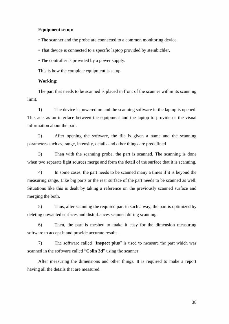
Figure 41- The Laser Scanning device.[29]
This is the laser scanner from “Steinbichler”. This is the equipment that is used in the
dimensional analysis. This has a scanner and a scanning probe.
38
Equipment setup:
• The scanner and the probe are connected to a common monitoring device.
• That device is connected to a specific laptop provided by steinbichler.
• The controller is provided by a power supply.
This is how the complete equipment is setup.
Working:
The part that needs to be scanned is placed in front of the scanner within its scanning
limit.
1) The device is powered on and the scanning software in the laptop is opened.
This acts as an interface between the equipment and the laptop to provide us the visual
information about the part.
2) After opening the software, the file is given a name and the scanning
parameters such as, range, intensity, details and other things are predefined.
3) Then with the scanning probe, the part is scanned. The scanning is done
when two separate light sources merge and form the detail of the surface that it is scanning.
4) In some cases, the part needs to be scanned many a times if it is beyond the
measuring range. Like big parts or the rear surface of the part needs to be scanned as well.
Situations like this is dealt by taking a reference on the previously scanned surface and
merging the both.
5) Thus, after scanning the required part in such a way, the part is optimized by
deleting unwanted surfaces and disturbances scanned during scanning.
6) Then, the part is meshed to make it easy for the dimension measuring
software to accept it and provide accurate results.
7) The software called “Inspect plus” is used to measure the part which was
scanned in the software called “Colin 3d” using the scanner.
After measuring the dimensions and other things. It is required to make a report
having all the details that are measured.
39
5. Water Assisted Injection Molding (WAIM).
ASSISTED INJECTION MOLDING.
The injection molding normally involves manufacturing of the product requested by
the customer. In which, there are many challenges while manufacturing a part. To,
overcome such circumstances, we adopt assisted injection molding.
It involves the usage of air or water to achieve the requirement for the requested part.
Especially at the places where there is a huge change in thickness of the part and to reduce
the weight of the part.
Hollowness in a part is created by this method. It either uses air or water and in some
cases both.
5.1. Gas assisted injection molding.(GAIM).
Gas Assist Injection Molding is one of the assisted molding technique, which uses
low-pressure nitrogen gas or other inert gases for applying even pressure for uniformity
throughout the molded part.
The gas is let go through the arears where the thickness is more and also to the areas
like edges.[30]
40
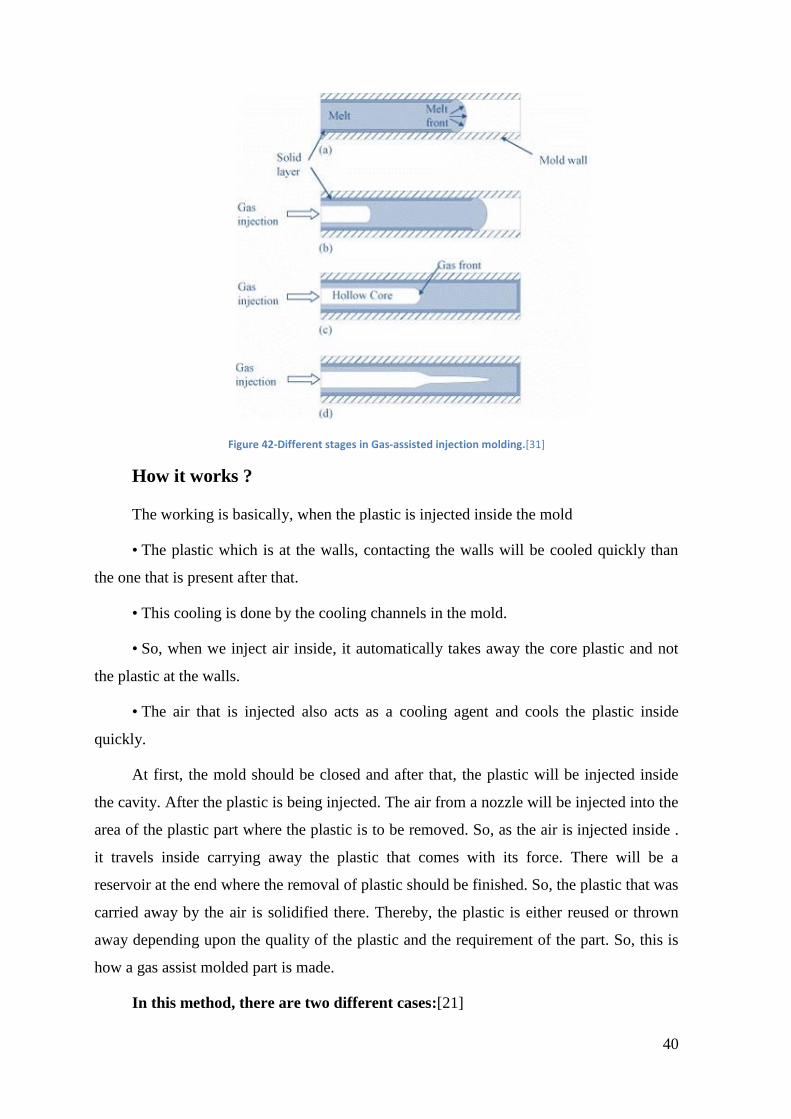
Figure 42-Different stages in Gas-assisted injection molding.[31]
How it works ?
The working is basically, when the plastic is injected inside the mold
• The plastic which is at the walls, contacting the walls will be cooled quickly than
the one that is present after that.
• This cooling is done by the cooling channels in the mold.
• So, when we inject air inside, it automatically takes away the core plastic and not
the plastic at the walls.
• The air that is injected also acts as a cooling agent and cools the plastic inside
quickly.
At first, the mold should be closed and after that, the plastic will be injected inside
the cavity. After the plastic is being injected. The air from a nozzle will be injected into the
area of the plastic part where the plastic is to be removed. So, as the air is injected inside .
it travels inside carrying away the plastic that comes with its force. There will be a
reservoir at the end where the removal of plastic should be finished. So, the plastic that was
carried away by the air is solidified there. Thereby, the plastic is either reused or thrown
away depending upon the quality of the plastic and the requirement of the part. So, this is
how a gas assist molded part is made.
In this method, there are two different cases:[21]
41
• The mold is filled short shot at first and then the gas is injected. So, as the gas
goes inside the pressure of the gas pushes the plastic towards the wall and
creates the hollowness. Mostly, in this case there won’t be a reservoir at the
end to collect the plastic as we inject less plastic at the very beginning itself.
• The other case is the one with the reservoir at the end to collect the plastic at
the end. Here, the plastic is filled completely in the mold.
Applications:
• It cools the part from the inside as well. Which eliminates the possibility of
warpage, sink marks and internal stress.
• This helps reductions in clamp tonnage, cycle time, and part weight and rigidity of
the part is increased.
• Parts with a lot of ribs, bosses and gussets are made perfectly flat without sink
marks and evenness.
• A lengthy part shape could be made less in drops. Also, eliminates weld lines &
tooling costs.
• In many gas assisted molds, the clamp tonnage and other parameters will be
reduced mostly by 50% or more.
External Gas Assist Injection Molding:
This is a bit different from internal gas assisted injection molding. Here, the gas will
be injected from the core part of the mold. The gas will be injected as a thin layer in-
between the core and back of the part.[3]
By this method, we will get a perfect and smooth surface at the front of the part, as it
normally cools the part surface evenly. We will not get sink marks in this method.
42
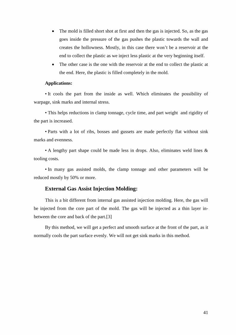
Figure 43- Effect of cooling in an External GAIM part.[31]
In figure 43,the left one is normal conventional molding where the cooling is done at
the bottom side .,i.e at the ribs side.
So what happens here is that, the thickness of plastic at the junction of rib have more
plastic and makes it difficult to be cooled at the same time when the other areas having
even thickness gets cooled.
So, the plastic at the rib gets cooled at first and it starts to shrink, which is propagated
towards the root where the junction lies. This is the reason why we get shrinkage.
At the right image, we have shrinkage at the sides of the rib since we have the gas
layer at the top of the part. It creates even cooling at the surface thereby, the shrinkage
occurs evenly at the top area leaving the shrinkage at the other sides.
5.2. Water assisted injection molding (WAIM)
This is the next type of molding found after gas assisted injection molding. This has
a lot of advantages over gas assisted molds.
As the name indicates, the main difference of this from gas is that it uses water to
take the plastic instead of gas. It has received a lot of appreciation in the recent years
because of its light weight products. This helps a lot to reduce the weight of the molded
part when compared to the former.
Ahmed Zia & Amir Hossein Behravesh [32] mentioned that, ”In 1998, the first report
was made on WAIM at the “Institut fur Kunststoffverarbeitung” (IKV), a plastics
processing development centre in Germany”.[33]
Water-assisted injection-molding technology has received extensive attention in
recent years, for its light weight products, relatively lower resin cost per part, faster cycle
43
time, and its flexibility in the design and manufacture of plastic parts. WAIM is especially
well suited for a number of hollow-parts applications, such as automotive fluid handling
tubes for oils and coolants, automotive door handles, oven and refrigerator handles, chain
saw handles, office furniture chair arms and so on.
WAIM has been under development for more than ten years and is already
successfully commercialized in Europe.
WAIM is the newest way to mold hollow or partly hollow parts. It’s basically similar
to GAIM as a means to core out thick sections. Generally, according to the volume of
injected melt, WAIM can be divided into short-shot process and full-shot process.
The main difference between these two is the way of filling the melt inside the
cavity. If the filling is done partially, it is short shot and if the filling is done completely, it
is full shot molding.
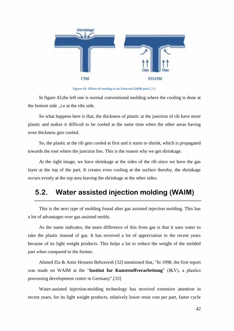
Short shot :
At first, the mold will be filled with the polymer partially and then, the water will be
injected inside. Which, when injected exerts pressure on the inner walls of the plastic and
forces the plastic to get completely in contact with the walls of the mold and it retains for a
while until the plastic melt solidifies as the required part. The cooling of the melt is carried
out by the same water that is injected at the beginning of the process. The water is let to
stay inside for a specific duration ensuring a perfect part.
Figure 44- The steps for a short-shot WAIM.[32]
44
After that, the water will be released or sucked outside the mold.
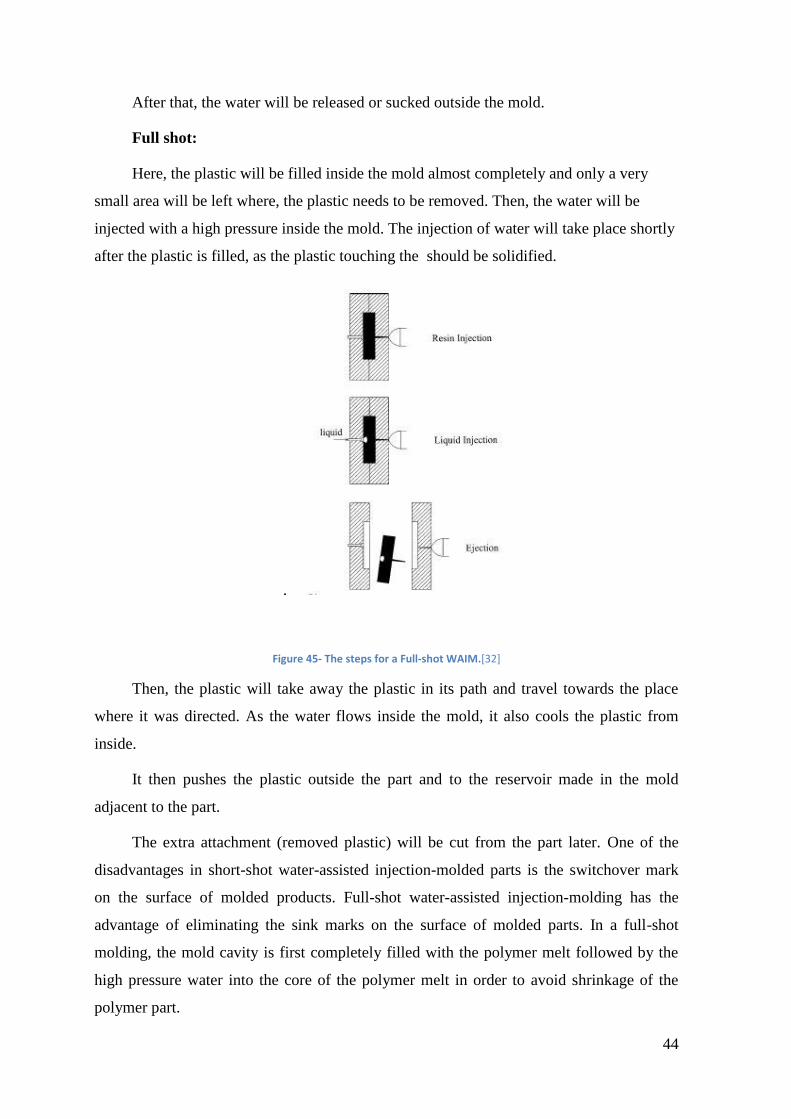
Full shot:
Here, the plastic will be filled inside the mold almost completely and only a very
small area will be left where, the plastic needs to be removed. Then, the water will be
injected with a high pressure inside the mold. The injection of water will take place shortly
after the plastic is filled, as the plastic touching the should be solidified.
.
Figure 45- The steps for a Full-shot WAIM.[32]
Then, the plastic will take away the plastic in its path and travel towards the place
where it was directed. As the water flows inside the mold, it also cools the plastic from
inside.
It then pushes the plastic outside the part and to the reservoir made in the mold
adjacent to the part.
The extra attachment (removed plastic) will be cut from the part later. One of the
disadvantages in short-shot water-assisted injection-molded parts is the switchover mark
on the surface of molded products. Full-shot water-assisted injection-molding has the
advantage of eliminating the sink marks on the surface of molded parts. In a full-shot
molding, the mold cavity is first completely filled with the polymer melt followed by the
high pressure water into the core of the polymer melt in order to avoid shrinkage of the
polymer part.
45
5.3. Water assisted injection molding at
MoldeTipo
There are many water injection molds that are being manufactured in company. The
parts that we manufactured had many defects and they were rectified as well. From which I
have learned some information about water injection molds and the process.
The reason why WAIM is chosen over GAIM are,
• Water assisted molds cools the part very rapidly. Thereby reduces the cycle time by
30% over gas assisted.
• This rapid cooling is due to the specific heat of water, which is more than 4 times
that of the gas. Also, the thermal conductivity is about 40 times higher.
• The plastic removed is much more compared to gas.
• The surface finish of the inner wall is smooth and the material removal rate is even.
Although, WAIM has many benefits over GAIM. The main problem here is the
voids. The formation voids in the residual walls of the part is the main problem in WAIM
parts.
Why voids are formed ?
• The fluid injected inside the plastic part to make it hollow includes Water and
silicone.
• The first reason for the formation of void is that the flow of the fluid in forming the
hollow section. If the fluid flow is unstable inside the mold during the melt removal, it
create voids.
• The secondary one is due to the varying residual wall thickness, that paves way to
shrinkage and eventually forms void.
• This varying cross section usually is formed in a curved area of the part. This is due
to the difference in the melt solidifying time at the outer and inner walls of the part.
The void occurrence at the residual wall of the hollow section is highly influenced by
semi-crystalline polymer, as it has large volumetric shrinkage. Which in turn, creates
solidification unevenly and forms void.
46
Furthermore, if glass fibre is added to the polymer to increase its reinforcement of
strength, it makes the polymer even more prone to voids.
In general, approximately 20% of the specific volume changes during the process
due to change in temperature and pressure of the polymer. This change is specific volume
creates shrinkage in the part. The volumetric shrinkage mostly occurs during the cooling
process which affects the dimensional accuracy and quality of the final product.
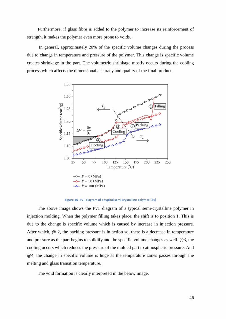
Figure 46- PvT diagram of a typical semi-crystalline polymer.[34]
The above image shows the PvT diagram of a typical semi-crystalline polymer in
injection molding. When the polymer filling takes place, the shift is to position 1. This is
due to the change is specific volume which is caused by increase in injection pressure.
After which, @ 2, the packing pressure is in action so, there is a decrease in temperature
and pressure as the part begins to solidify and the specific volume changes as well. @3, the
cooling occurs which reduces the pressure of the molded part to atmospheric pressure. And
@4, the change in specific volume is huge as the temperature zones passes through the
melting and glass transition temperature.
The void formation is clearly interpreted in the below image,
47
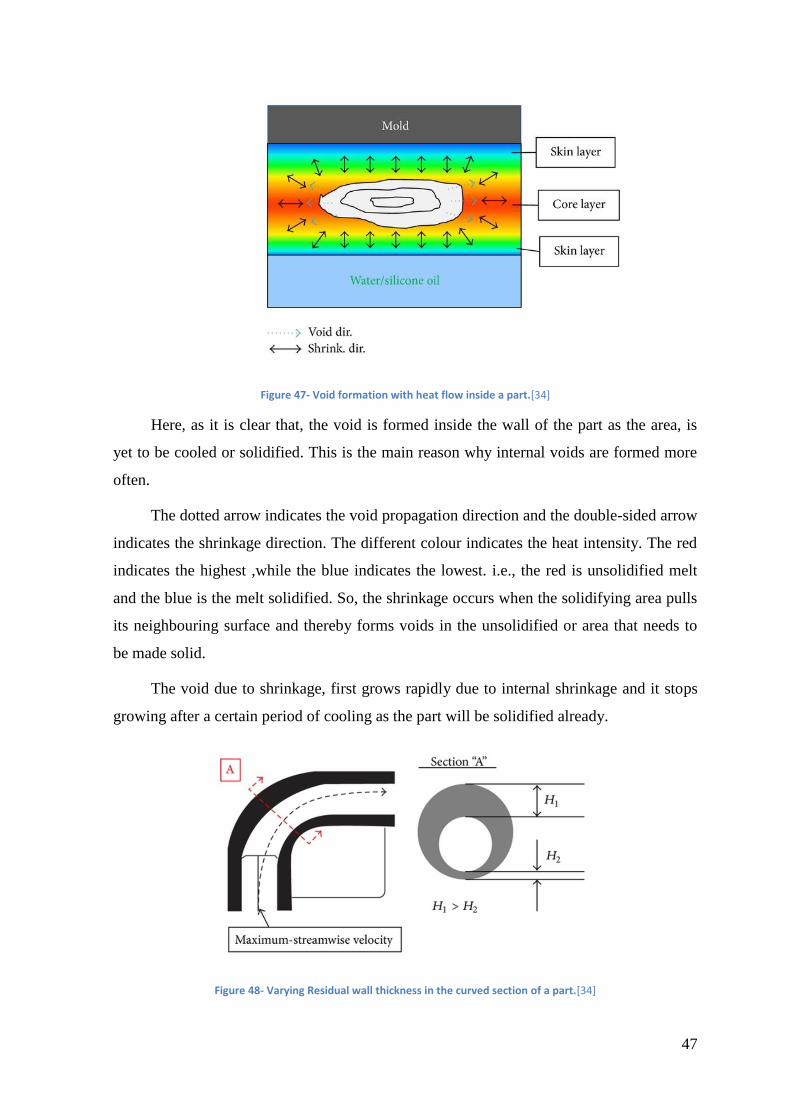
Figure 47- Void formation with heat flow inside a part.[34]
Here, as it is clear that, the void is formed inside the wall of the part as the area, is
yet to be cooled or solidified. This is the main reason why internal voids are formed more
often.
The dotted arrow indicates the void propagation direction and the double-sided arrow
indicates the shrinkage direction. The different colour indicates the heat intensity. The red
indicates the highest ,while the blue indicates the lowest. i.e., the red is unsolidified melt
and the blue is the melt solidified. So, the shrinkage occurs when the solidifying area pulls
its neighbouring surface and thereby forms voids in the unsolidified or area that needs to
be made solid.
The void due to shrinkage, first grows rapidly due to internal shrinkage and it stops
growing after a certain period of cooling as the part will be solidified already.
Figure 48- Varying Residual wall thickness in the curved section of a part.[34]
48
At the time of fluid injection to form hollow section, the removal of plastic and the
residual wall thickness is even in straight areas, whereas in curved areas, the thickness of
the residual wall is uneven and not uniform.
The outer thickness of the wall will be more than that of the inner wall thickness. The
reason for this is, mainly the centrifugal force generated by the fluid flowing in the curved
area.
There are other parameters that contribute for the development of WAIM. The water
penetration during the creation of hollow section is very important. There are factors that
affect the penetration of water inside the part during the process of injection.
5.4. Important parameters for WAIM.
To understand the WAIM process even more deeply, a study of different parameters
that effects the process of WAIM is done. From which the important aspects that needs to
be considered are studied precisely.
Ahmed zia & Amir Hossein behravesh published an article titled “ An Experimental
investigation on water penetration in the process of water assisted injection molding of
polypropylene”. Where they have taken some important parameters that effects the WAIM
process and experimented them to identify the ideal requirements to achieve maximum
penetration for a best product .[35]
Another study conducted by the same duo, Ahmed zia & Amir Hossein
behravesh[36] on Effects of process parameters in water assisted injection molding of
ABS, have made an experimental analysis of the parameters delay time, holding time and
mold temperature. The results gave an idea of how effective these parameters are when
manufacturing a water assisted injection molding part.
A series of experiments has been conducted to understand the process intensity at the
change of each parameter.
ANALYSIS ON POLYPROPYLENE:
The part is shaped like a branched tree with two heads, one is straight and the other is
bent to an angle from the straight to know the effect clearly.
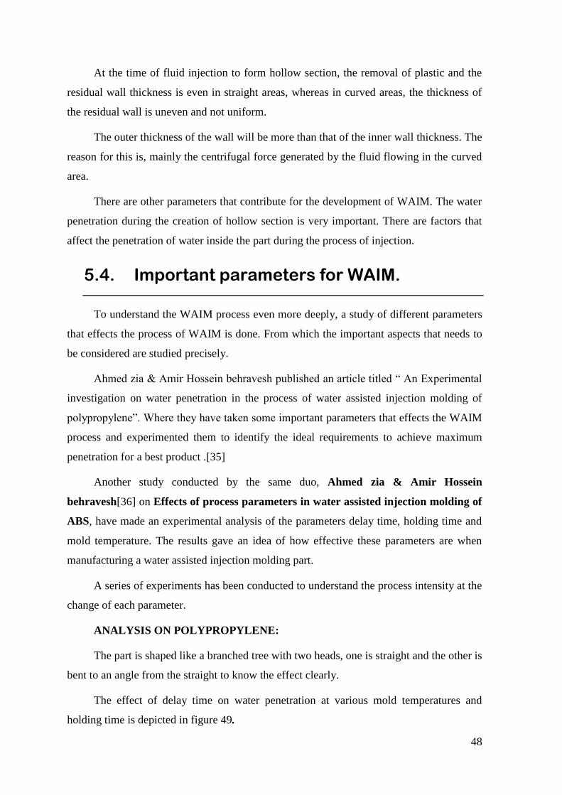
The effect of delay time on water penetration at various mold temperatures and
holding time is depicted in figure 49.
49
Figure 49-Water penetration on mold temperature.[35]
This is the graph plotted with the holding time of 5sec, it is evident from it, that the
penetration increases with increase in mold temperature at different mold temperatures.
The reason being, the warm temperature. As the temperature is warmer inside the
mold, it slows down plastic becoming solid and also, the temperature assists penetration by
decreasing the plastic resistance.
The result was almost the same for the remaining, where the maximum penetration
occurred at 40°c also the mold temperature is more responsive at lower delay time(2.5s).
This is because the plastic just starts to plasticize giving more penetration length for water.
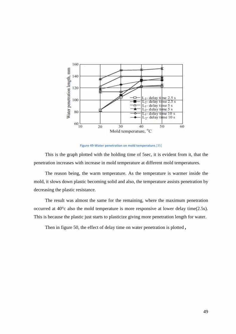
Then in figure 50, the effect of delay time on water penetration is plotted ,
50
Figure 50- Water penetration on Delay time [35]
This gives us the penetration length, which is highest at a delay time of 5 sec, falls
shortly after preceding delay times. This is due to the increasing cooling time of the plastic
which creates more resistance on the surface of the melt ,thereby obstructing the flow of
water.
Also at times below 5sec time, lower penetration length is observed, which is
because, the plastic will just start to solidify leaving a large amount of melt melted and so,
the water injected won’t have a specific path to flow and starts to flow in many directions
and thereby reducing the penetration.
ANALYSIS ON ABS:
The same part, that is shaped like a branched tree with two heads, one is straight and
the other is bent to an angle from the straight is taken here for the ABS as well.
The effect of delay time, holding time and mold temperature on water penetration
and hollow core diameter are studied. The delay times of 0, 2.5, 5 and 10 sec are chosen.
Holding times of 5 sec and 10sec are chosen and mold temperatures of 30°, 40° and 50°c
are chosen.
The measurement starts at 50mm from the gate and ends for the straight leg at
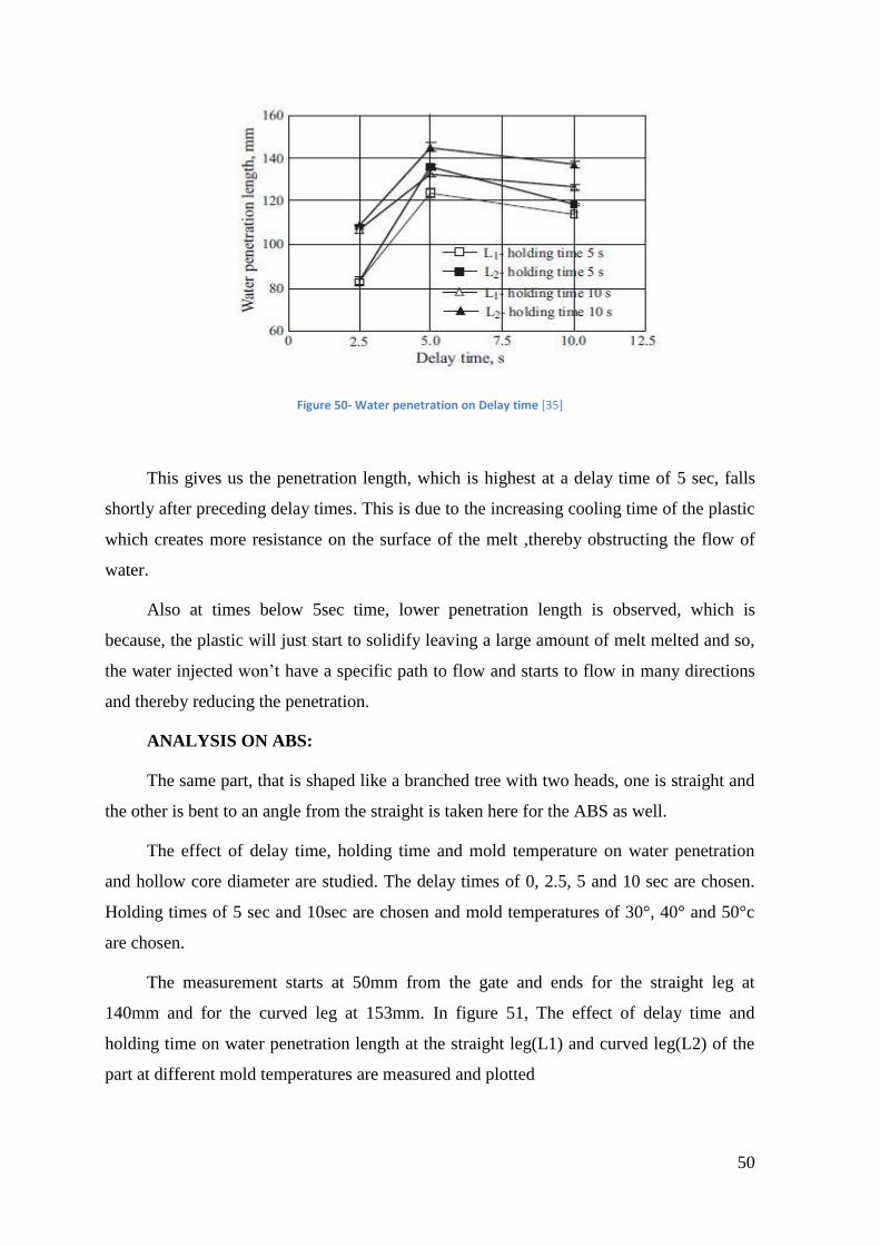
140mm and for the curved leg at 153mm. In figure 51, The effect of delay time and
holding time on water penetration length at the straight leg(L1) and curved leg(L2) of the
part at different mold temperatures are measured and plotted
51
Figure 51-Effect plotted at 40°C.[34]
From the graph, it is clear that the water penetration increases with increase in delay
time up to a certain point and then decreases after that. The maximum water penetration
occurred at a delay time of 2.5sec at all the mold temperatures
It behaved with a slight difference when the mold temperature is 50°c, where it lasted
till 5 sec of delay time.
At the higher delay times the penetration decreased because the solidification of the
melt inside the mold takes place and thereby, the melt that should be removed by the water
injected is solidified at the inner wall of the part and due to which the water penetration
reduces as delay time increases.
Even at zero delay time, There is penetration. But it is very less as compared to more
delay time. In this case, we will have sink marks in the part surface as there would be a
huge thickness difference in the residual wall and it will also have voids.
The effect of mold temperature on water penetration length at various delay times are
justified in figure 52.
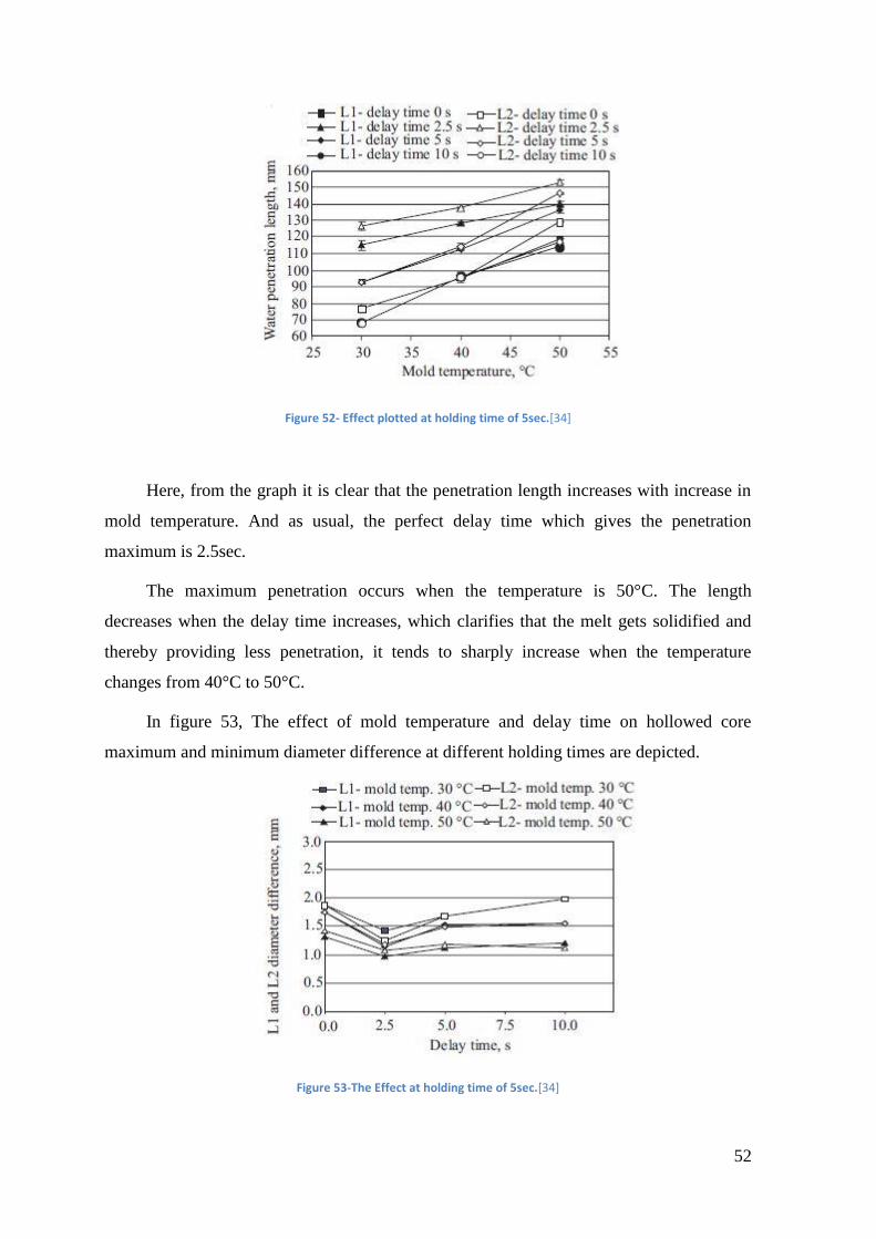
52
Figure 52- Effect plotted at holding time of 5sec.[34]
Here, from the graph it is clear that the penetration length increases with increase in
mold temperature. And as usual, the perfect delay time which gives the penetration
maximum is 2.5sec.
The maximum penetration occurs when the temperature is 50°C. The length
decreases when the delay time increases, which clarifies that the melt gets solidified and
thereby providing less penetration, it tends to sharply increase when the temperature
changes from 40°C to 50°C.
In figure 53, The effect of mold temperature and delay time on hollowed core
maximum and minimum diameter difference at different holding times are depicted.
Figure 53-The Effect at holding time of 5sec.[34]
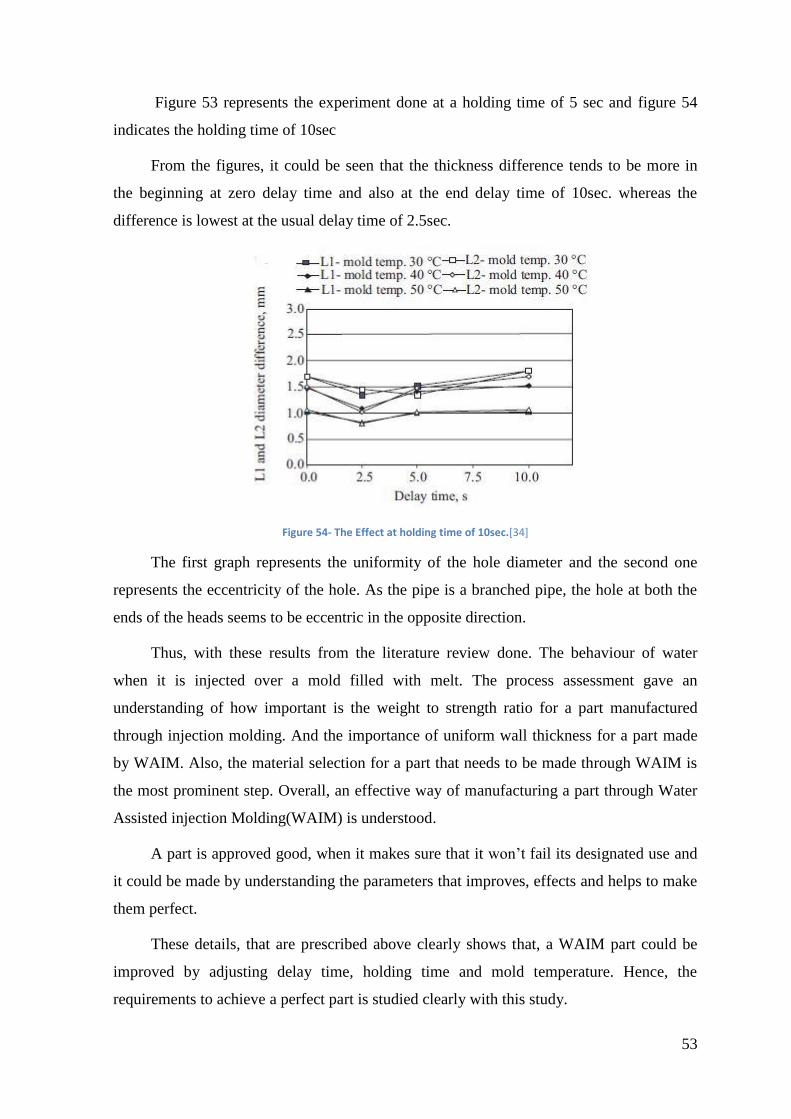
53
Figure 53 represents the experiment done at a holding time of 5 sec and figure 54
indicates the holding time of 10sec
From the figures, it could be seen that the thickness difference tends to be more in
the beginning at zero delay time and also at the end delay time of 10sec. whereas the
difference is lowest at the usual delay time of 2.5sec.
Figure 54- The Effect at holding time of 10sec.[34]
The first graph represents the uniformity of the hole diameter and the second one
represents the eccentricity of the hole. As the pipe is a branched pipe, the hole at both the
ends of the heads seems to be eccentric in the opposite direction.
Thus, with these results from the literature review done. The behaviour of water
when it is injected over a mold filled with melt. The process assessment gave an
understanding of how important is the weight to strength ratio for a part manufactured
through injection molding. And the importance of uniform wall thickness for a part made
by WAIM. Also, the material selection for a part that needs to be made through WAIM is
the most prominent step. Overall, an effective way of manufacturing a part through Water
Assisted injection Molding(WAIM) is understood.
A part is approved good, when it makes sure that it won’t fail its designated use and
it could be made by understanding the parameters that improves, effects and helps to make
them perfect.
These details, that are prescribed above clearly shows that, a WAIM part could be
improved by adjusting delay time, holding time and mold temperature. Hence, the
requirements to achieve a perfect part is studied clearly with this study.

54
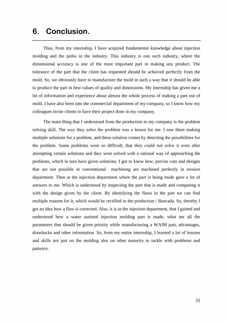
55
6. Conclusion.
Thus, from my internship, I have acquired fundamental knowledge about injection
molding and the perks in the industry. This industry is one such industry, where the
dimensional accuracy is one of the most important part in making any product. The
tolerance of the part that the client has requested should be achieved perfectly from the
mold. So, we obviously have to manufacture the mold in such a way that it should be able
to produce the part in best values of quality and dimensions. My internship has given me a
lot of information and experience about almost the whole process of making a part out of
mold. I have also been into the commercial department of my company, so I know how my
colleagues invite clients to have their project done in my company.
The main thing that I understood from the production in my company is the problem
solving skill. The way they solve the problem was a lesson for me. I saw them making
multiple solutions for a problem, and these solution comes by detecting the possibilities for
the problem. Some problems were so difficult, that they could not solve it even after
attempting certain solutions and they were solved with a rational way of approaching the
problems, which in turn have given solutions. I got to know how, precise cuts and designs
that are not possible in conventional machining are machined perfectly in erosion
department. Then at the injection department where the part is being made gave a lot of
answers to me. Which is understood by inspecting the part that is made and comparing it
with the design given by the client. By identifying the flaws in the part we can find
multiple reasons for it, which would be rectified in the production / Bancada. So, thereby I
got an idea how a flaw is corrected. Also, it is in the injection department, that I gained and
understood how a water assisted injection molding part is made, what are all the
parameters that should be given priority while manufacturing a WAIM part, advantages,
drawbacks and other information. So, from my entire internship, I learned a lot of lessons
and skills not just on the molding also on other maturity to tackle with problems and
patience.

56
57
References
[1] G. Potsch and W. Michaeli, Injection Molding An Introduction. 2008.
[2] “Machine parts,” sinotech, 2017. [Online]. Available:
https://www.sinotech.com/resources/tutorials/injection-molded-parts/. [Accessed:
02-Mar-2017].
[3] F. Johannaber, Injection molding machines : a user’s guide. Munich, Germany;
Cincinnati, Ohio: Carl Hanser Publishers ; Hanser Gardner Publications, 2008.
[4] “Machine components,” Engineering education, 2011. [Online]. Available:
http://www.dc.engr.scu.edu/cmdoc/dg_doc/develop/process/control/b1000002.htm.
[Accessed: 25-May-2017].
[5] M. L. Berins and S. of the P. Industry., “SPI plastics engineering handbook of the
Society of the Plastics Industry, Inc.” Kluwer Academic Publishers, Boston; New
York, 2001.
[6] R. Dangel and R. Dangel, “2 – Mould Types,” in Injection Moulds for Beginners,
2016, pp. 3–42.
[7] “Design Approaches,” Proto labs, 2017. [Online]. Available:
https://www.protolabs.com/resources/design-tips/improving-part-moldability-with-
draft/. [Accessed: 15-Mar-2017].
[8] S. Dalton, “Mould Design,” 2011. [Online]. Available:
http://staffweb.itsligo.ie/staff/sdalton/ptooling/Mould-Design-slides.pdf. [Accessed:
20-Mar-2017].
[9] W. Michaeli, H. Greif, G. Kretzschmar, and F. Ehrig, “Training in Injection
Molding,” in Training in Injection Molding, Carl Hanser Verlag GmbH & Co. KG,
2001, pp. i–4.
[10] “Cooling channel.” [Online]. Available: http://www.lbc-
engineering.de/en/conformal-cooling.php. [Accessed: 23-Mar-2017].
[11] Tuula, “Mould standard parts.,” 2007. [Online]. Available:
http://webhotel2.tut.fi/projects/caeds/tekstit/mould/mould_starndard_parts.pdf.
[Accessed: 25-Mar-2017].
58
[12] “Steels used in Injection Mold making,” 2015. [Online]. Available:
http://info.crescentind.com/blog/bid/66085/Understand-Common-Steels-Used-in-
Injection-Mold-Making. [Accessed: 27-Mar-2017].
[13] “stratasysdirect,” 2017. [Online]. Available:
https://www.stratasysdirect.com/materials/tooling-molding/. [Accessed: 29-Mar-
2017].
[14] A. Materials, “Data sheet of P20 steel composition.,” 2017. [Online]. Available:
http://www.azom.com/article.aspx?ArticleID=6239. [Accessed: 20-Sep-2017].
[15] Doerrenberg, “Data sheet of 1.2312 40CrMnNiMo steel.,” 2005. [Online].
Available: http://metallurgicaveneta.it/pdf_eng/acciai-da-utensili-per-lavorazioni-a-
caldo/1.2312.pdf. [Accessed: 20-Sep-2017].
[16] Doerrenberg, “Data sheet of 1.1730 steel.,” 2005. [Online]. Available:
www.doerrenberg.de/uploads/tx_c1x1downloads/1.1730_en.pdf. [Accessed: 20-
Sep-2017].
[17] “Major defects in plastic Injection molding.,” 2016. [Online]. Available:
https://www.creativemechanisms.com/blog/what-cause-injection-molding-defects-
and-how-to-fix-them. [Accessed: 28-Apr-2017].
[18] “Plastic warpage,” 2009. [Online]. Available:
http://exploringcad.blogspot.pt/2009/03/plastic-componets-design-
considerations.html. [Accessed: 30-Apr-2017].
[19] “Types of Injecrion molding gates.,” Engineering education, 2011. [Online].
Available:
http://www.dc.engr.scu.edu/cmdoc/dg_doc/develop/design/gate/32000002.htm.
[Accessed: 01-May-2017].
[20] “Important factors to injection molding,” 2015. [Online]. Available:
http://info.crescentind.com/blog/bid/59146/5-Factors-Important-to-Injection-
Molding. [Accessed: 02-May-2017].
[21] R. J. Crawford, Plastics engineering. Butterworth-Heinemann, 1998.
[22] “Melt Flow Rate,” 2017. [Online]. Available: http://www.misumi-
techcentral.com/tt/en/mold/2012/01/107.html. [Accessed: 14-May-2017].
59
[23] D. Industry, “3-Axis CNC,” 2017. [Online]. Available:
http://www.directindustry.com/prod/diversified-machine-systems/product-101789-
1360335.html. [Accessed: 21-May-2017].
[24] “A brief about the process of milling.,” Custompartnet, 2017. [Online]. Available:
http://www.custompartnet.com/wu/milling. [Accessed: 20-Sep-2017].
[25] “How edm works.” [Online]. Available: http://www.xactedm.com/edm-
capabilities/how-edm-works/. [Accessed: 01-Jun-2017].
[26] “EDM Principles,” 2017. [Online]. Available:
http://mechanicalinventions.blogspot.pt/2016/01/electrical-discharge-machining-
edm.html. [Accessed: 07-Jun-2017].
[27] “An Intro to Electrical Discharge Machining,” KEEN home, 2017. [Online].
Available: https://shop.keenhome.io/blogs/community/an-intro-to-electrical-
discharge-machining. [Accessed: 07-Jun-2017].
[28] “Precision Cutting,” ORIGIN Engineering, 2016. [Online]. Available:
http://www.originengineering.com.au/precision_cutting.html. [Accessed: 07-Jun-
2017].
[29] “Steinbichler – 3D-Scanner aus Deutschland,” 2017. [Online]. Available:
https://3druck.com/scanner/steinbichler-3d-scanner-aus-deutschland-2724830/.
[30] H. Belofsky, Plastics : Product design and process engineering. Hanser Gardner
Pubns (April 1995), 1995.
[31] Sajarplastics, “What is gas-assist-injection-molding,” 2017. [Online]. Available:
http://sajarplastics.com/what-is-gas-assist-injection-molding/. [Accessed: 20-Sep-
2017].
[32] S.-J. Liu and Y.-S. Chen, “The manufacturing of thermoplastic composite parts by
water-assisted injection-molding technology,” Compos. Part A Appl. Sci. Manuf.,
vol. 35, pp. 171–180, Feb. 2004.
[33] T. Jüntgen and W. Michaeli, “THE WATER INJECTION TECHNIQUE ( WIT )
AS AN ATTRACTIVE ALTERNATIVE AND SUPPLEMENT TO GAS-
ASSISTED INJECTION MOLDING ( GAIM ) Plant and injector technology
Comparison of GAIM and WIT,” Proc. ANTEC 2002, 2002.
60
[34] K.-H. L. Hyung-Pil Park, Baeg-Soon Cha, Soo-Bin Park, Jae-Hyuk Choi, Dong-Han
Kim, Byung-Ohk Rhee, “A study on the Void Formation in Residual Wall
Thickness of Fluid-Assisted Injection Molding Parts,” Adv. Mater. Sci. Eng., vol.
2014, p. 06, 2014.
[35] A. Z. Ahmadzai and A. H. Behravesh, “An experimental investigation on water
penetration in the process of water assisted injection molding of polypropylene,”
Polimery/Polymers, vol. 54, no. 7–8, 2009.
[36] A. Z. Ahmadzai and A. H. Behravesh, “Effect of processing parameters on water
penetration in water assisted injection molding of ABS,” Polimery/Polymers, vol.
56, no. 3, 2011.

61
This page was intetionally left blank

62
Appendices

63
This page was intetionally left blank

64
Glossary


![[IJET V2I5P22] Authors: Gangasani Ravikumar Reddy, M.Suneetha](https://img.pdfslide.us/doc/110x75/587096461a28ab412b8b684d/ijet-v2i5p22-authors-gangasani-ravikumar-reddy-msuneetha.jpg)