Embed Size (px)
Citation preview
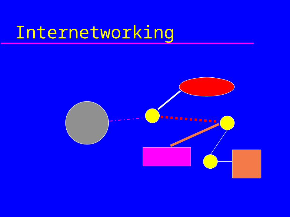
Internetworking
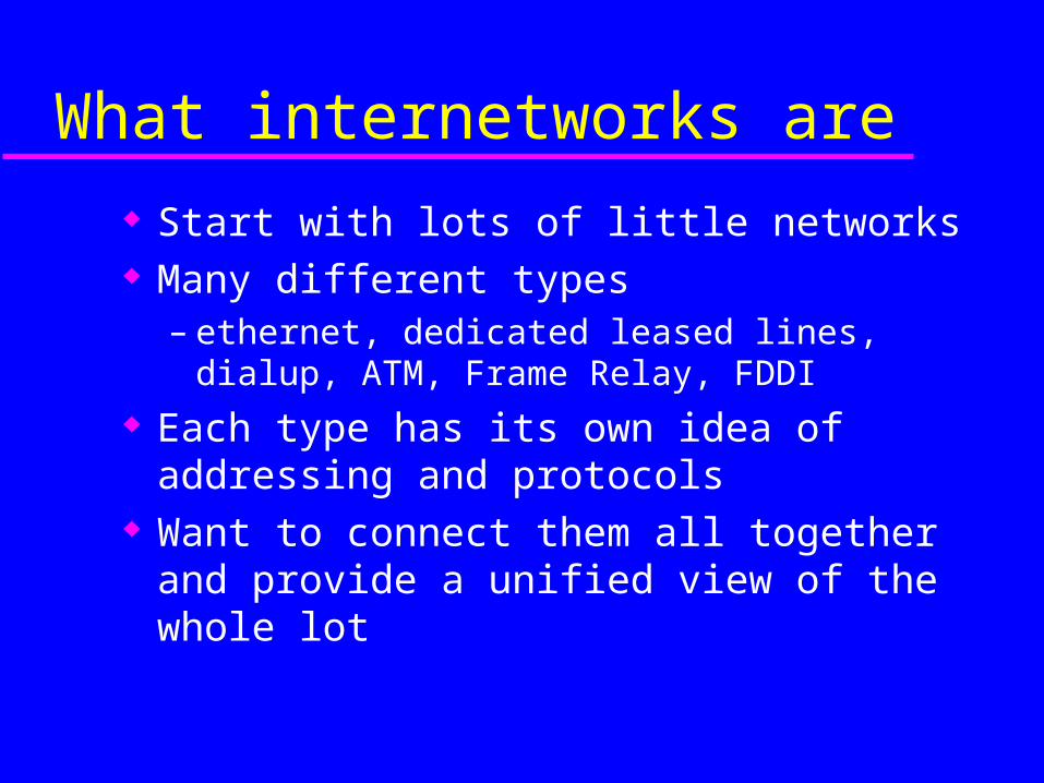
What internetworks are
Start with lots of little networks Many different types
– ethernet, dedicated leased lines, dialup, ATM, Frame Relay, FDDI
Each type has its own idea of addressing and protocols
Want to connect them all together and provide a unified view of the whole lot
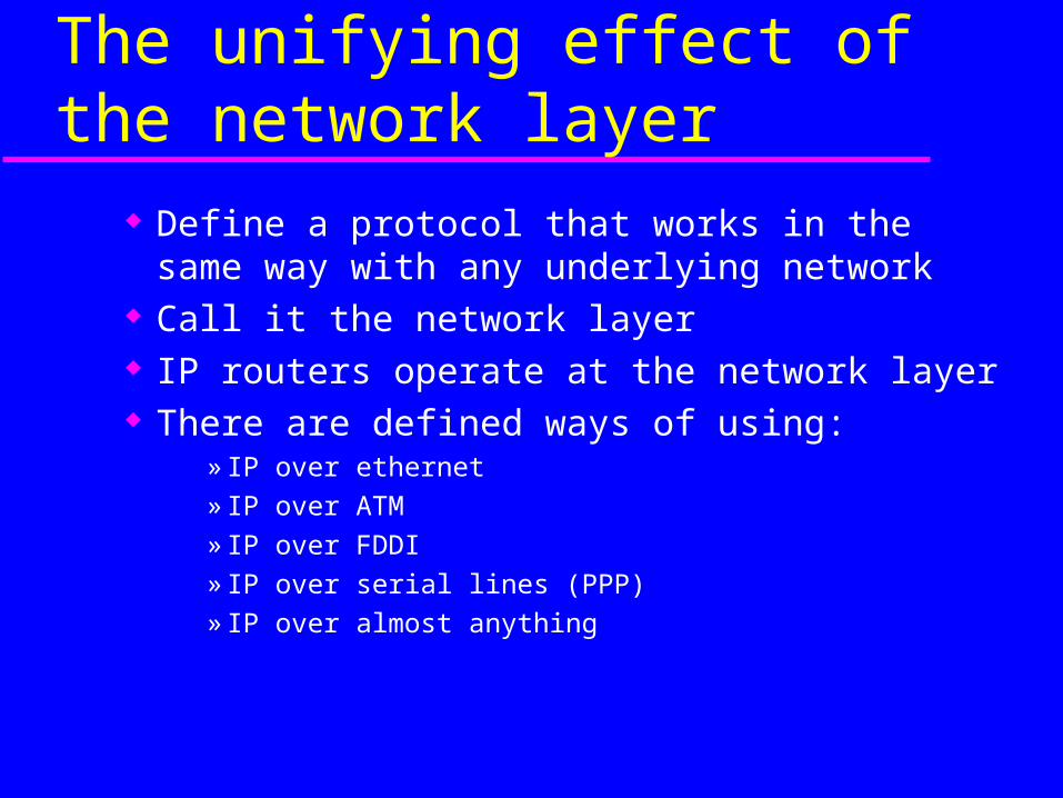
The unifying effect of the network layer
Define a protocol that works in the same way with any underlying network
Call it the network layer IP routers operate at the network layer There are defined ways of using:
» IP over ethernet
» IP over ATM
» IP over FDDI
» IP over serial lines (PPP)
» IP over almost anything
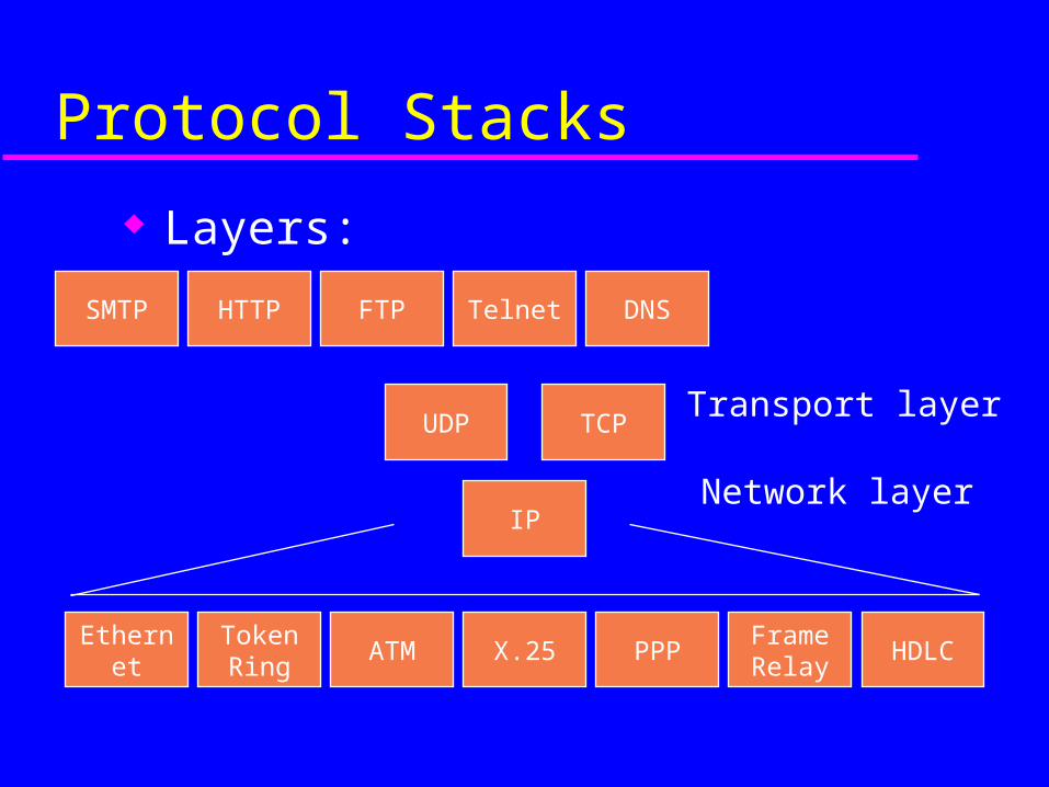
Protocol Stacks
Layers:
Network layer
Transport layer
Token Ring
ATM X.25 PPPFrame Relay
HDLCEthernet
IP
TCPUDP
HTTP FTP Telnet DNSSMTP
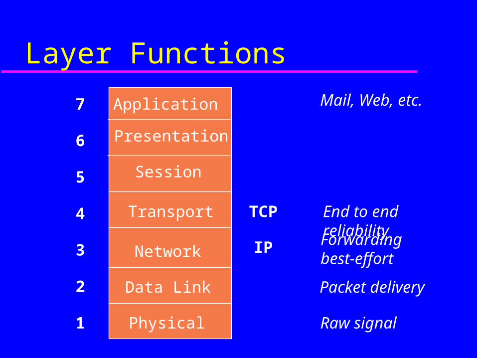
Layer Functions
Physical
Data Link
Network
Transport
IP
TCP End to end reliability
Forwardingbest-effort
Packet delivery
Raw signal
Application Mail, Web, etc.
Session
Presentation
1
3
2
4
5
6
7
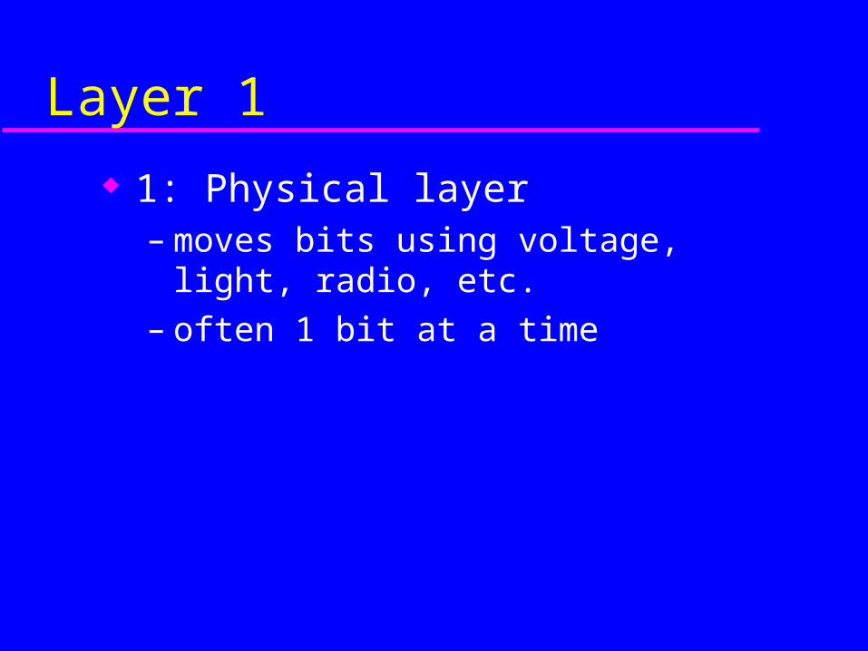
Layer 1
1: Physical layer– moves bits using voltage, light, radio, etc.– often 1 bit at a time
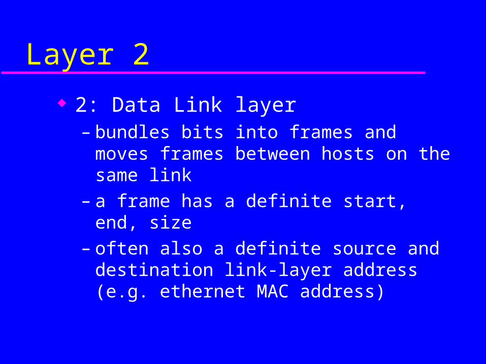
Layer 2
2: Data Link layer– bundles bits into frames and moves frames
between hosts on the same link– a frame has a definite start, end, size– often also a definite source and destination
link-layer address (e.g. ethernet MAC address)
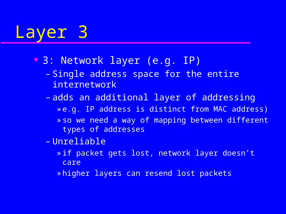
Layer 3
3: Network layer (e.g. IP)– Single address space for the entire internetwork– adds an additional layer of addressing
» e.g. IP address is distinct from MAC address)
» so we need a way of mapping between different types of addresses
– Unreliable» if packet gets lost, network layer doesn’t care
» higher layers can resend lost packets
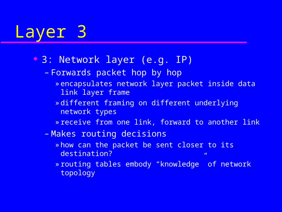
Layer 3
3: Network layer (e.g. IP)– Forwards packet hop by hop
» encapsulates network layer packet inside data link layer frame
» different framing on different underlying network types» receive from one link, forward to another link
– Makes routing decisions» how can the packet be sent closer to its destination?» routing tables embody “knowledge” of network
topology
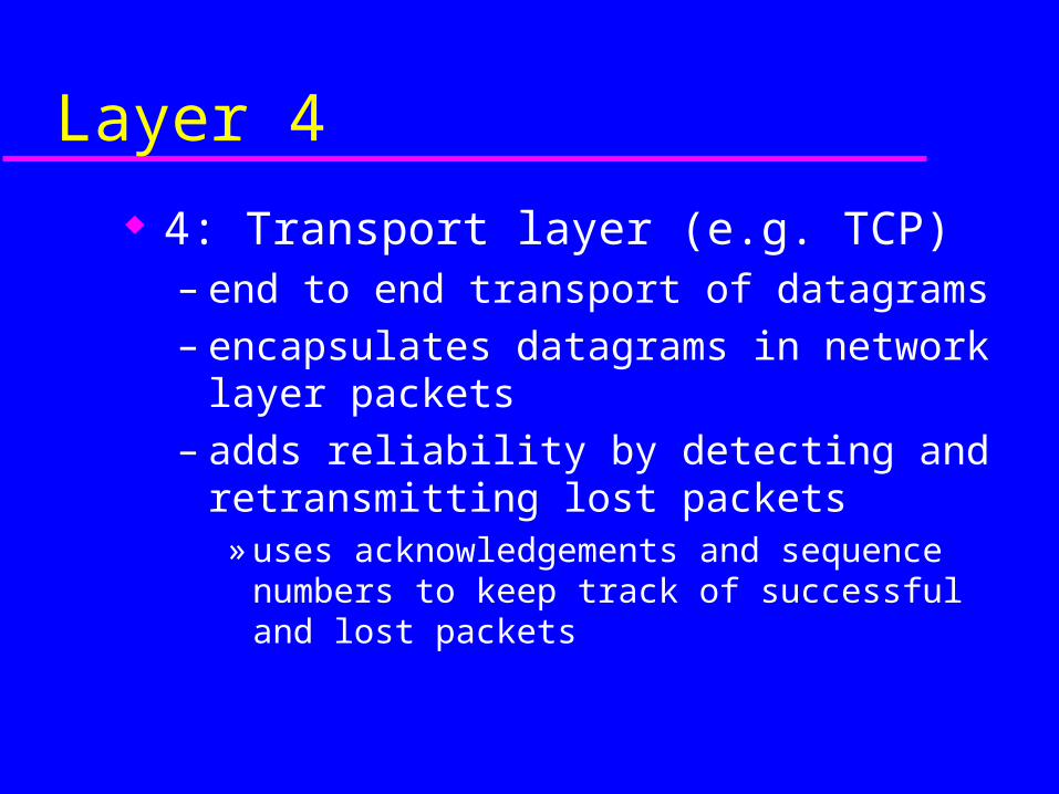
Layer 4
4: Transport layer (e.g. TCP)– end to end transport of datagrams– encapsulates datagrams in network layer
packets– adds reliability by detecting and retransmitting
lost packets» uses acknowledgements and sequence numbers to
keep track of successful and lost packets
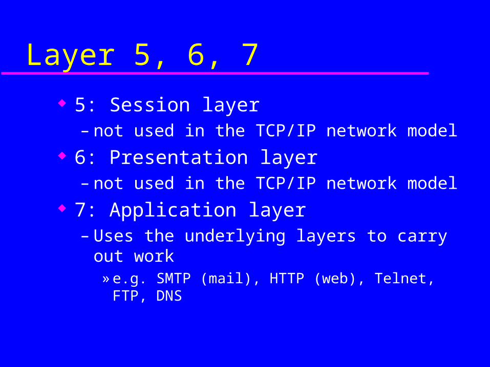
Layer 5, 6, 7
5: Session layer– not used in the TCP/IP network model
6: Presentation layer– not used in the TCP/IP network model
7: Application layer– Uses the underlying layers to carry out work
» e.g. SMTP (mail), HTTP (web), Telnet, FTP, DNS
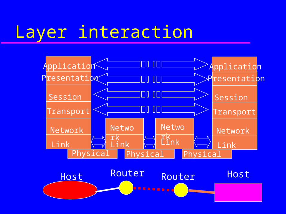
Layer interaction
Presentation
Session
Transport
Network
LinkPhysical
Link
Network
Physical Physical
Link
Application
Network
Host Router Router Host
Presentation
Session
Transport
Network
Link
Application
Layer interaction
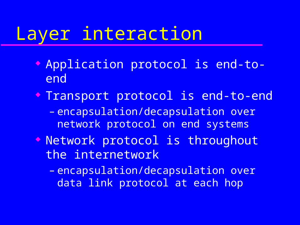
Application protocol is end-to-end Transport protocol is end-to-end
– encapsulation/decapsulation over network protocol on end systems
Network protocol is throughout the internetwork– encapsulation/decapsulation over data link
protocol at each hop
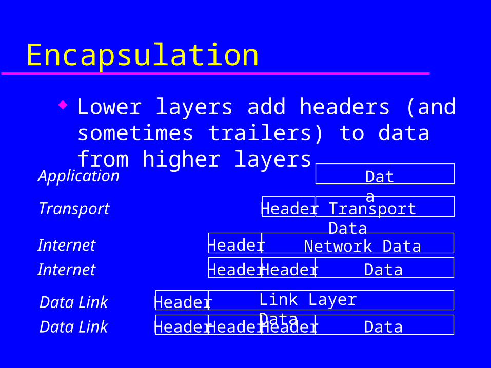
Encapsulation
Lower layers add headers (and sometimes trailers) to data from higher layers
Data
Transport Data
Network Data
Link Layer Data
Header
Header
Header
Application
Transport
Internet
Data Link
DataHeaderHeader HeaderData Link
DataHeaderHeaderInternet
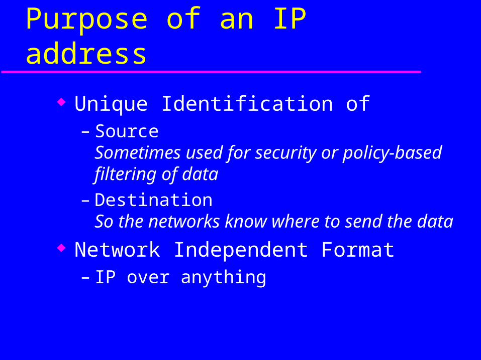
Purpose of an IP address
Unique Identification of – Source
Sometimes used for security or policy-based filtering of data
– DestinationSo the networks know where to send the data
Network Independent Format– IP over anything
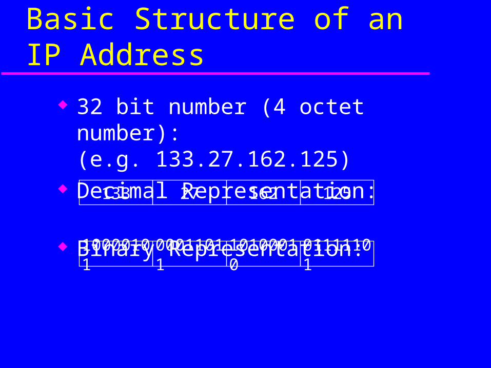
32 bit number (4 octet number):(e.g. 133.27.162.125)
Decimal Representation:
Binary Representation:
Basic Structure of an IP Address
133 27 162 125
10000101 00011011 10100010 01111101
A
C
B
FE
I
G
D
H
J
RouterPC
HUB
RouterPC
HUB
RouterPC
HUB
RouterPC
HUB
RouterPC
HUB
Router PC
HUB
Router PC
HUB
Router PC
HUB
Router PC
HUB
Router PC
HUB
SWITCH
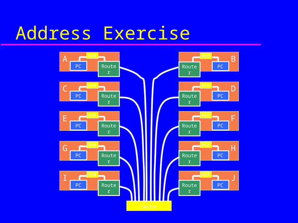
Address Exercise
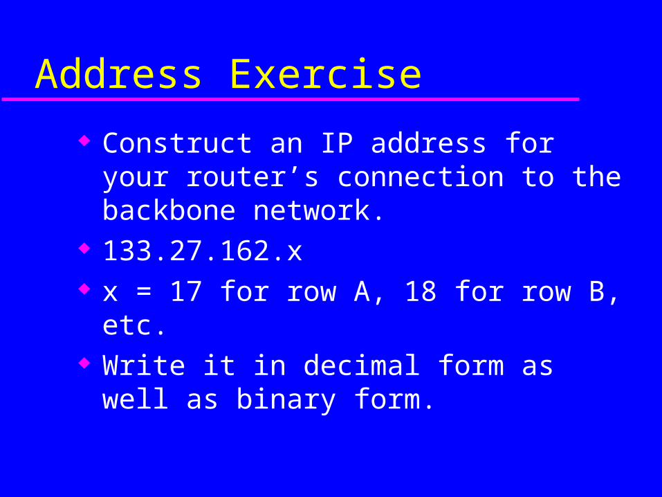
Address Exercise
Construct an IP address for your router’s connection to the backbone network.
133.27.162.x x = 17 for row A, 18 for row B, etc. Write it in decimal form as well as binary
form.
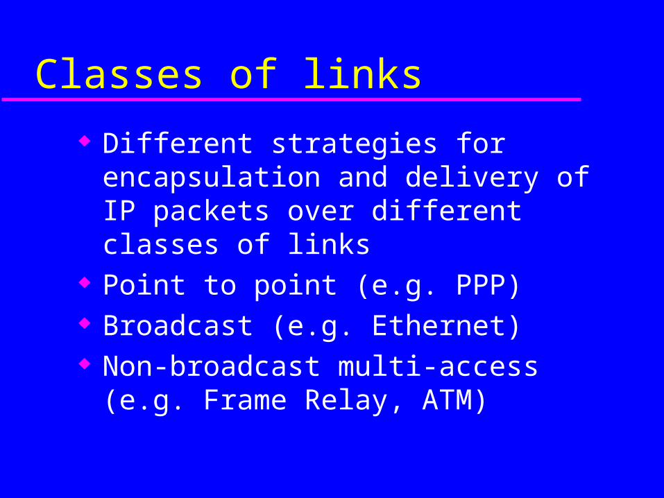
Classes of links
Different strategies for encapsulation and delivery of IP packets over different classes of links
Point to point (e.g. PPP) Broadcast (e.g. Ethernet) Non-broadcast multi-access (e.g. Frame
Relay, ATM)

Encapsulation
Lower layers add headers (and sometimes trailers) to data from higher layers
Data
Transport Data
Network Data
Link Layer Data
Header
Header
Header
Application
Transport
Internet
Data Link
DataHeaderHeader HeaderData Link
DataHeaderHeaderInternet
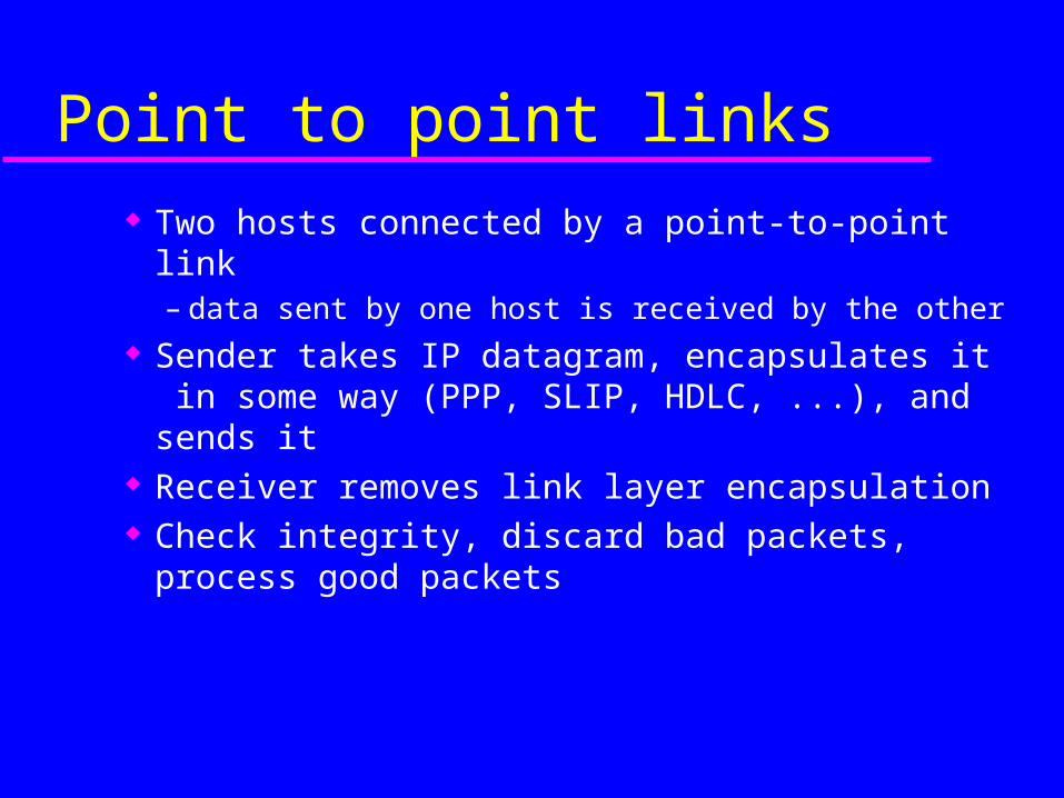
Point to point links
Two hosts connected by a point-to-point link– data sent by one host is received by the other
Sender takes IP datagram, encapsulates it in some way (PPP, SLIP, HDLC, ...), and sends it
Receiver removes link layer encapsulation Check integrity, discard bad packets, process
good packets
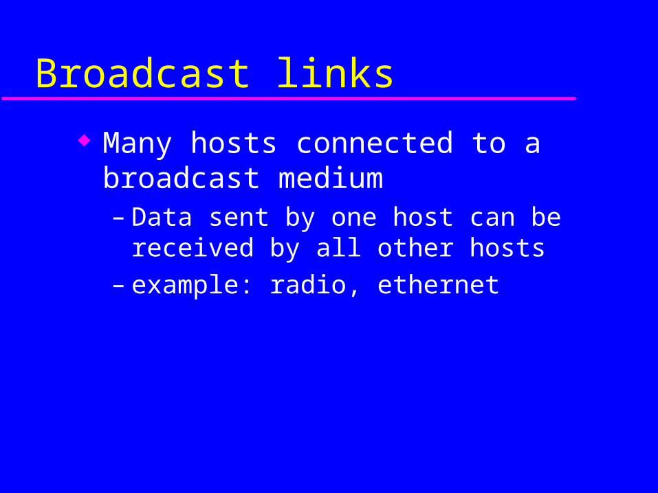
Broadcast links
Many hosts connected to a broadcast medium– Data sent by one host can be received by all
other hosts– example: radio, ethernet
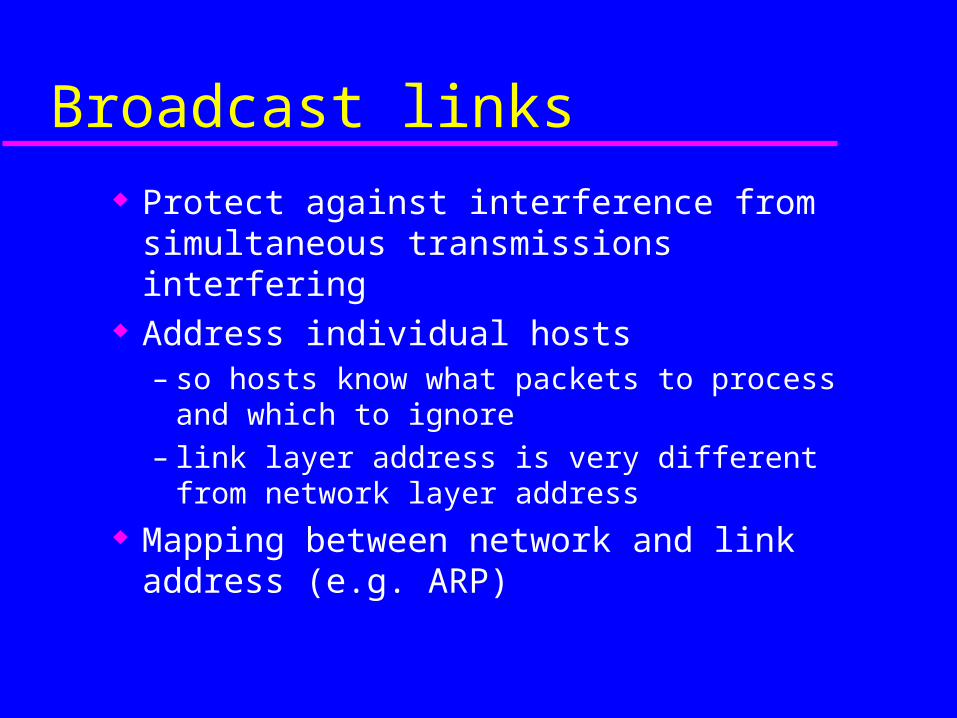
Broadcast links
Protect against interference from simultaneous transmissions interfering
Address individual hosts– so hosts know what packets to process and which to
ignore– link layer address is very different from network
layer address Mapping between network and link address
(e.g. ARP)
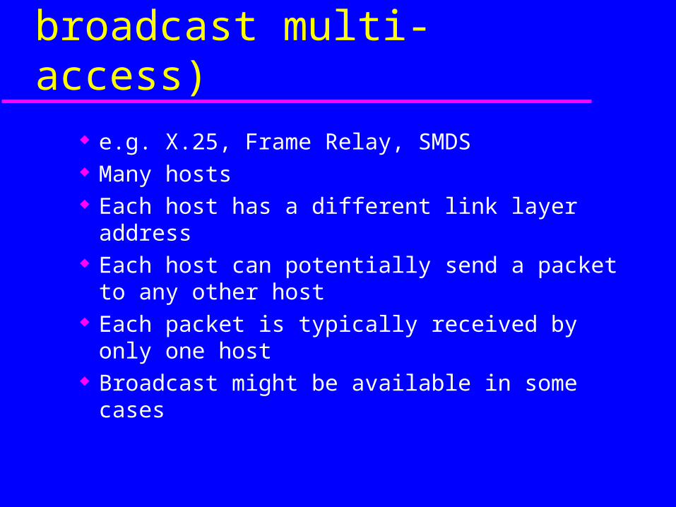
NBMA links (Non-broadcast multi-access)
e.g. X.25, Frame Relay, SMDS Many hosts Each host has a different link layer address Each host can potentially send a packet to any
other host Each packet is typically received by only one
host Broadcast might be available in some cases
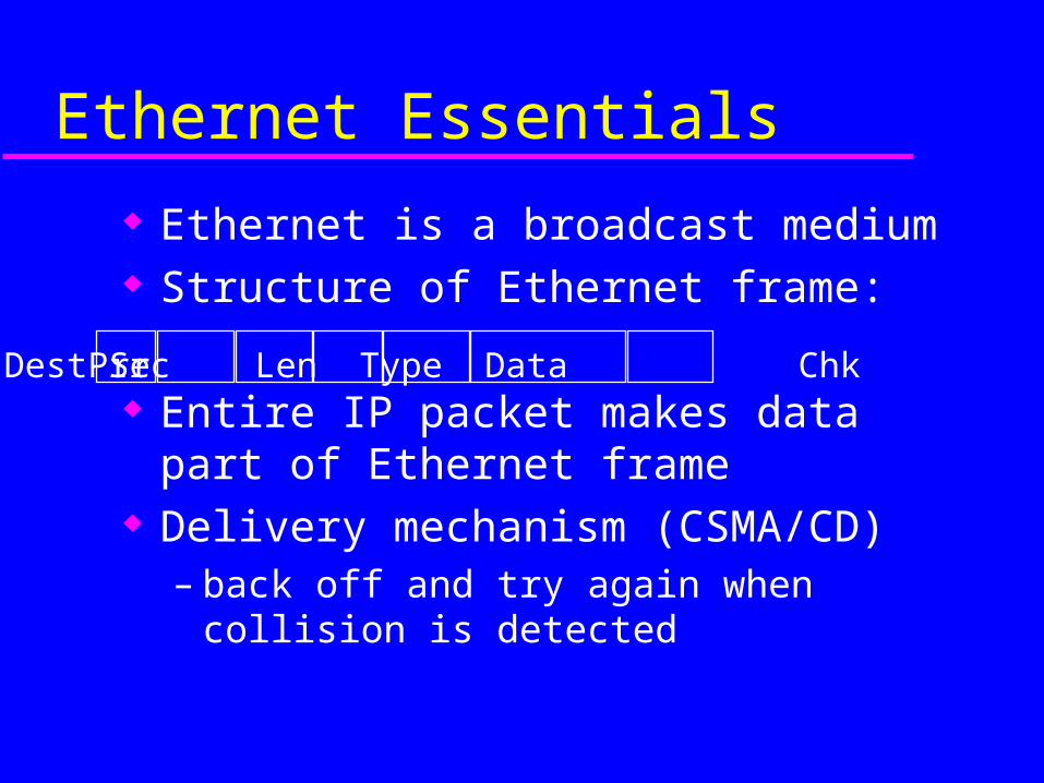
Ethernet Essentials
Ethernet is a broadcast medium Structure of Ethernet frame:
Entire IP packet makes data part of Ethernet frame
Delivery mechanism (CSMA/CD)– back off and try again when collision is detected
Dest Src Len Type Data ChkPre
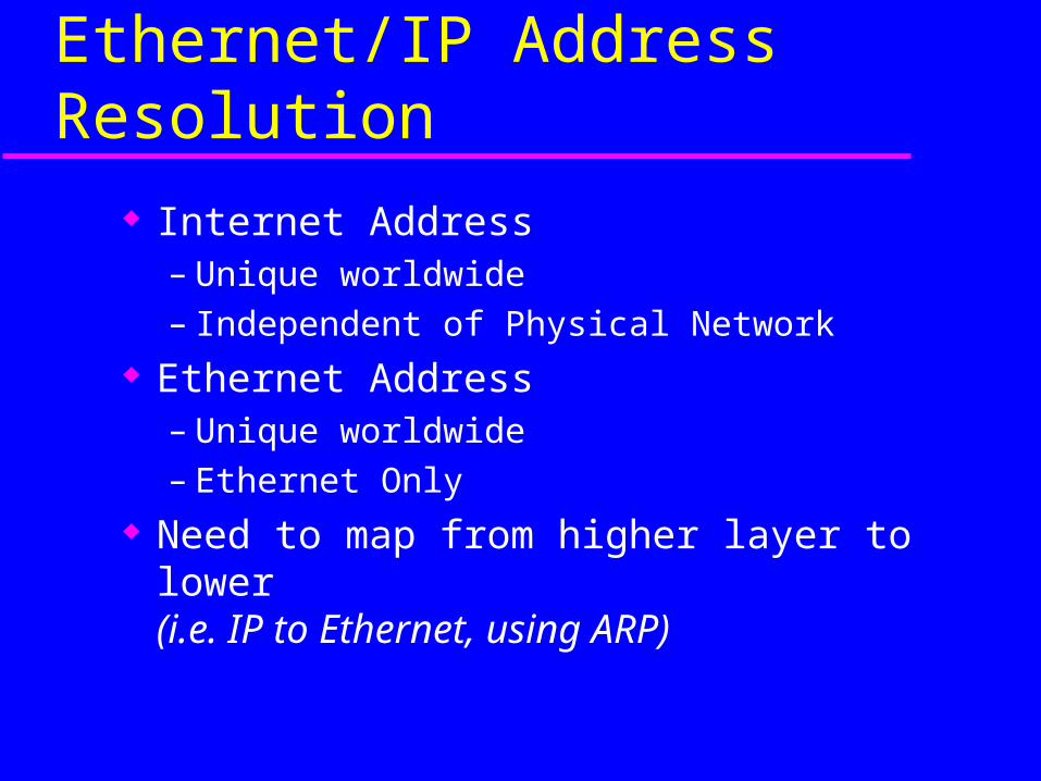
Ethernet/IP Address Resolution
Internet Address– Unique worldwide– Independent of Physical Network
Ethernet Address– Unique worldwide– Ethernet Only
Need to map from higher layer to lower(i.e. IP to Ethernet, using ARP)
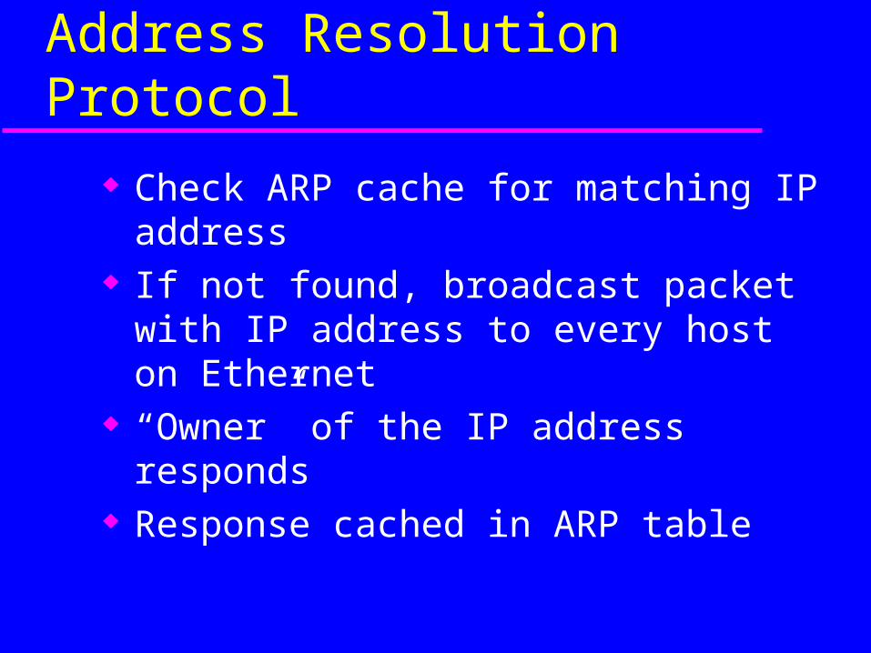
Address Resolution Protocol
Check ARP cache for matching IP address If not found, broadcast packet with IP
address to every host on Ethernet “Owner” of the IP address responds Response cached in ARP table
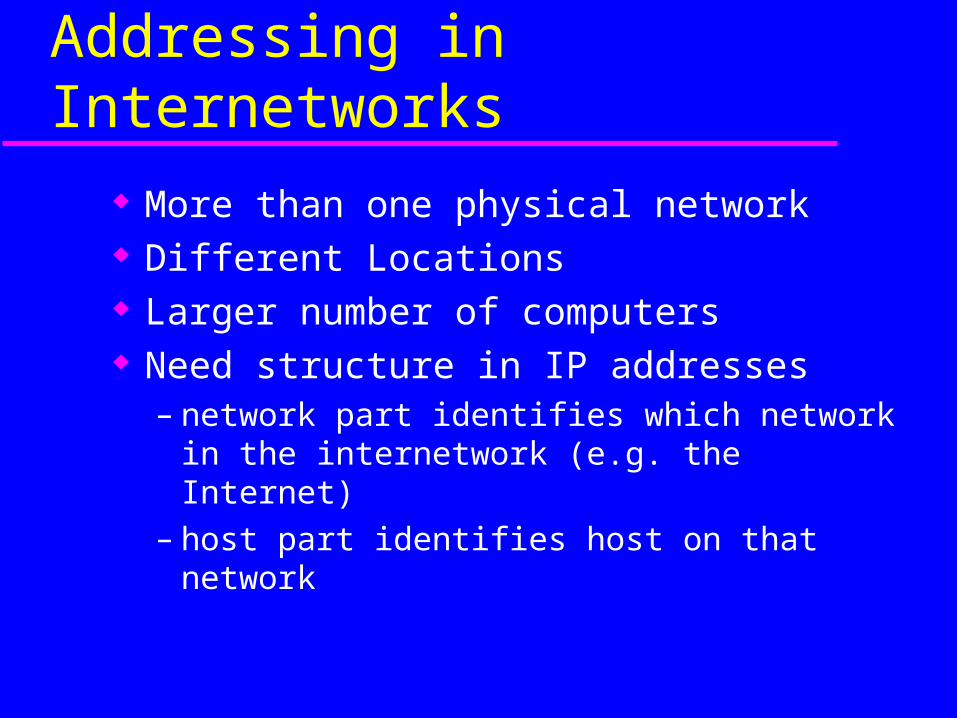
Addressing in Internetworks
More than one physical network Different Locations Larger number of computers Need structure in IP addresses
– network part identifies which network in the internetwork (e.g. the Internet)
– host part identifies host on that network
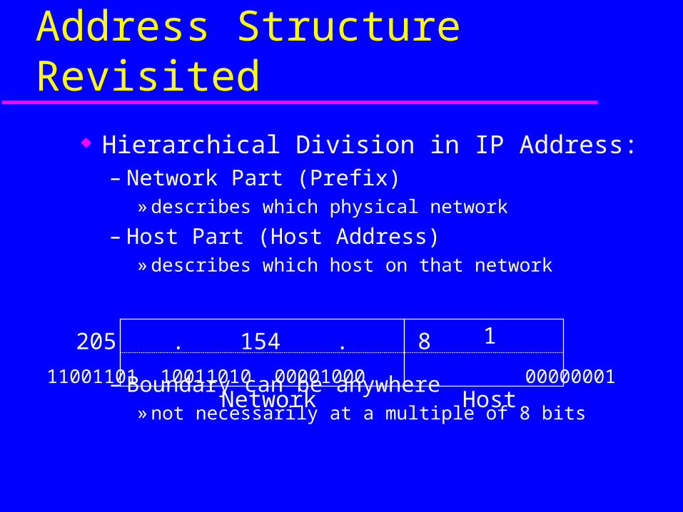
Address Structure Revisited
Hierarchical Division in IP Address:– Network Part (Prefix)
» describes which physical network
– Host Part (Host Address)» describes which host on that network
– Boundary can be anywhere» not necessarily at a multiple of 8 bits
Network Host
205 . 154 . 8 1
11001101 10011010 00001000 00000001
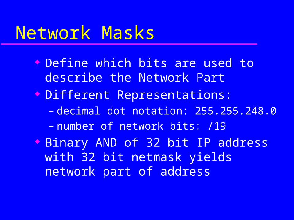
Network Masks
Define which bits are used to describe the Network Part
Different Representations:– decimal dot notation: 255.255.248.0– number of network bits: /19
Binary AND of 32 bit IP address with 32 bit netmask yields network part of address
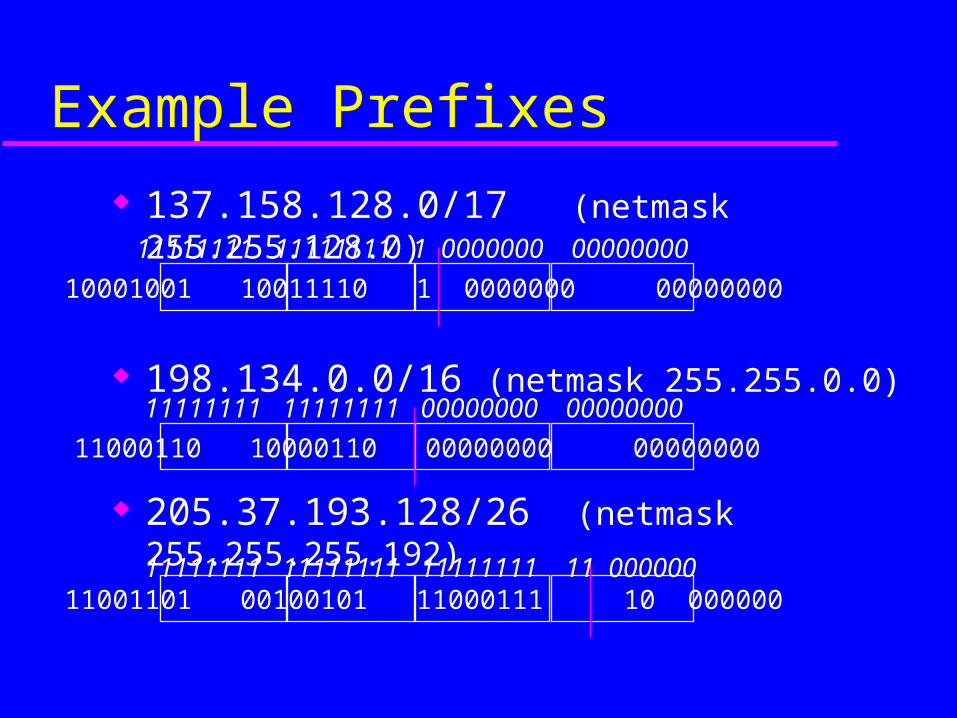
Example Prefixes
137.158.128.0/17 (netmask 255.255.128.0)
198.134.0.0/16 (netmask 255.255.0.0)
205.37.193.128/26 (netmask 255.255.255.192)
10001001 10011110 1 0000000 00000000
11000110 10000110 00000000 00000000
11001101 00100101 11000111 10 000000
11111111 11111111 1 0000000 00000000
11111111 11111111 11111111 11 000000
11111111 11111111 00000000 00000000
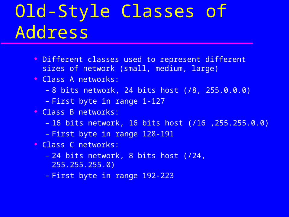
Old-Style Classes of Address Different classes used to represent different sizes of network
(small, medium, large) Class A networks:
– 8 bits network, 24 bits host (/8, 255.0.0.0)– First byte in range 1-127
Class B networks:– 16 bits network, 16 bits host (/16 ,255.255.0.0)– First byte in range 128-191
Class C networks:– 24 bits network, 8 bits host (/24, 255.255.255.0)– First byte in range 192-223
Special Addresses
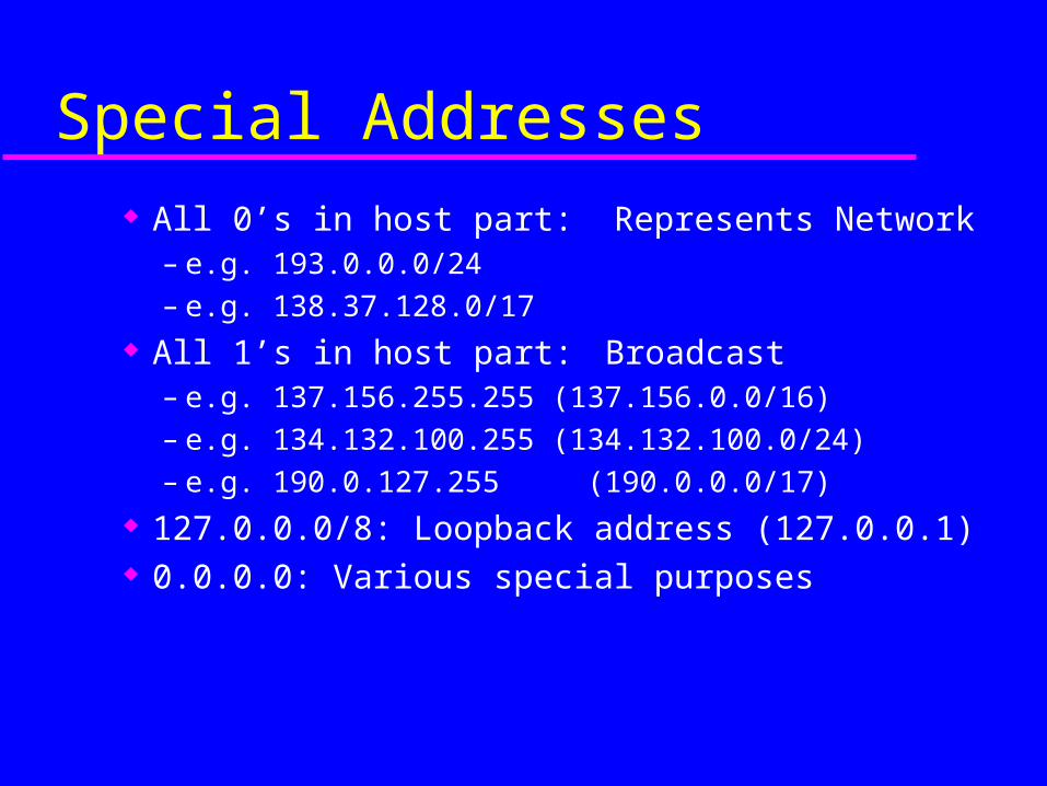
All 0’s in host part: Represents Network– e.g. 193.0.0.0/24– e.g. 138.37.128.0/17
All 1’s in host part: Broadcast– e.g. 137.156.255.255 (137.156.0.0/16)– e.g. 134.132.100.255 (134.132.100.0/24)– e.g. 190.0.127.255 (190.0.0.0/17)
127.0.0.0/8: Loopback address (127.0.0.1) 0.0.0.0: Various special purposes
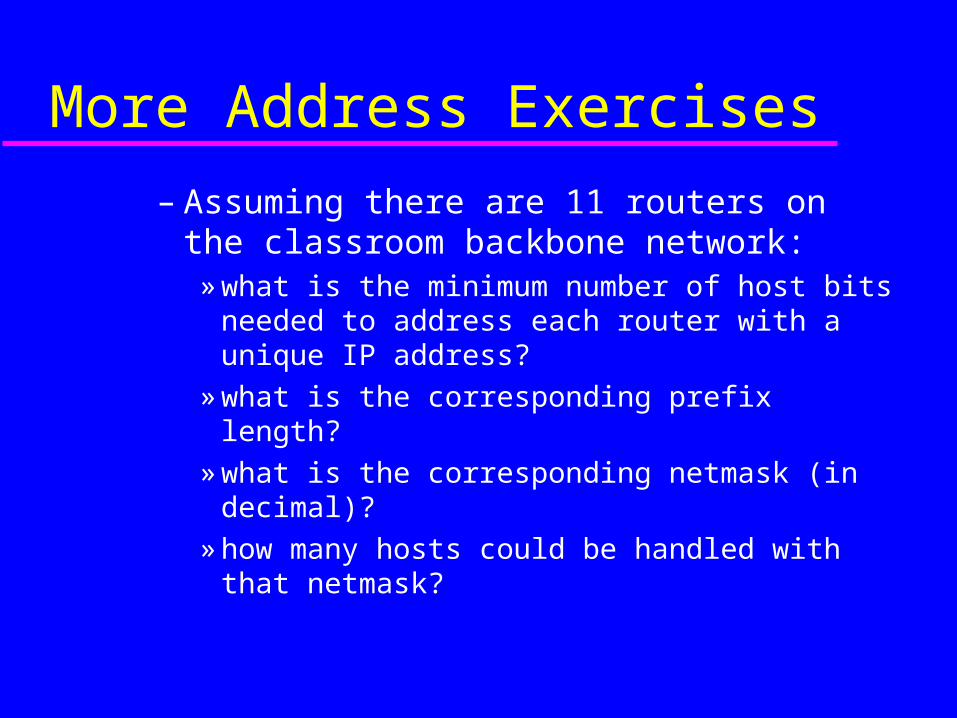
More Address Exercises
– Assuming there are 11 routers on the classroom backbone network:
» what is the minimum number of host bits needed to address each router with a unique IP address?
» what is the corresponding prefix length?
» what is the corresponding netmask (in decimal)?
» how many hosts could be handled with that netmask?
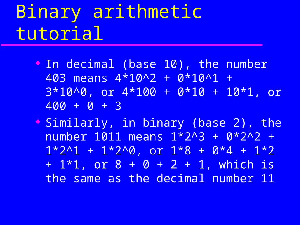
Binary arithmetic tutorial
In decimal (base 10), the number 403 means 4*10^2 + 0*10^1 + 3*10^0, or 4*100 + 0*10 + 10*1, or 400 + 0 + 3
Similarly, in binary (base 2), the number 1011 means 1*2^3 + 0*2^2 + 1*2^1 + 1*2^0, or 1*8 + 0*4 + 1*2 + 1*1, or 8 + 0 + 2 + 1, which is the same as the decimal number 11
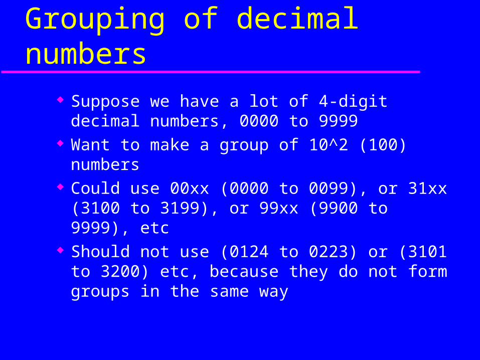
Grouping of decimal numbers
Suppose we have a lot of 4-digit decimal numbers, 0000 to 9999
Want to make a group of 10^2 (100) numbers Could use 00xx (0000 to 0099), or 31xx
(3100 to 3199), or 99xx (9900 to 9999), etc Should not use (0124 to 0223) or (3101 to
3200) etc, because they do not form groups in the same way
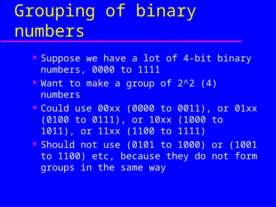
Grouping of binary numbers
Suppose we have a lot of 4-bit binary numbers, 0000 to 1111
Want to make a group of 2^2 (4) numbers Could use 00xx (0000 to 0011), or 01xx (0100 to
0111), or 10xx (1000 to 1011), or 11xx (1100 to 1111)
Should not use (0101 to 1000) or (1001 to 1100) etc, because they do not form groups in the same way
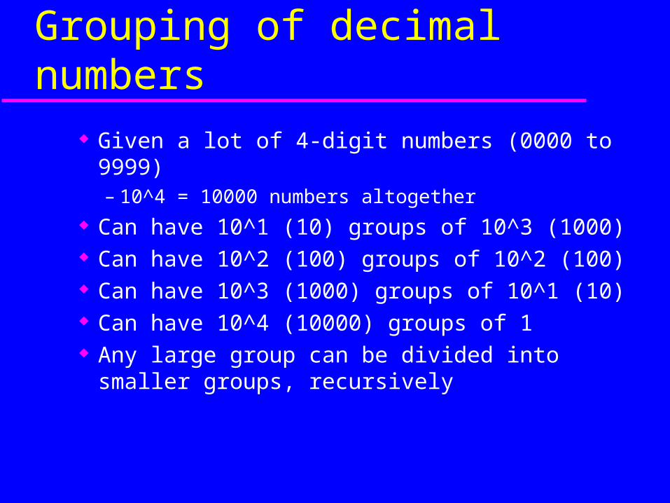
Grouping of decimal numbers
Given a lot of 4-digit numbers (0000 to 9999)– 10^4 = 10000 numbers altogether
Can have 10^1 (10) groups of 10^3 (1000) Can have 10^2 (100) groups of 10^2 (100) Can have 10^3 (1000) groups of 10^1 (10) Can have 10^4 (10000) groups of 1 Any large group can be divided into smaller
groups, recursively
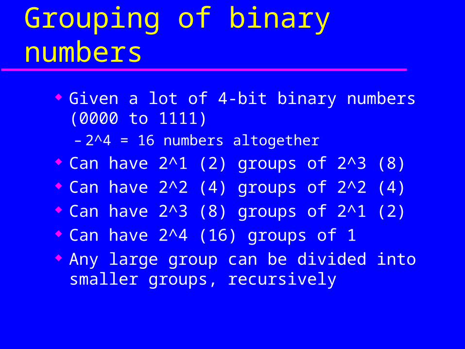
Grouping of binary numbers
Given a lot of 4-bit binary numbers (0000 to 1111)– 2^4 = 16 numbers altogether
Can have 2^1 (2) groups of 2^3 (8) Can have 2^2 (4) groups of 2^2 (4) Can have 2^3 (8) groups of 2^1 (2) Can have 2^4 (16) groups of 1 Any large group can be divided into smaller
groups, recursively
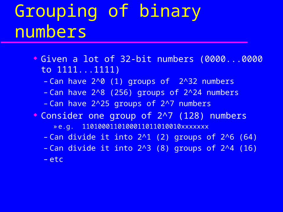
Grouping of binary numbers Given a lot of 32-bit numbers (0000...0000 to
1111...1111)– Can have 2^0 (1) groups of 2^32 numbers– Can have 2^8 (256) groups of 2^24 numbers– Can have 2^25 groups of 2^7 numbers
Consider one group of 2^7 (128) numbers» e.g. 1101000110100011011010010xxxxxxx
– Can divide it into 2^1 (2) groups of 2^6 (64)– Can divide it into 2^3 (8) groups of 2^4 (16)– etc
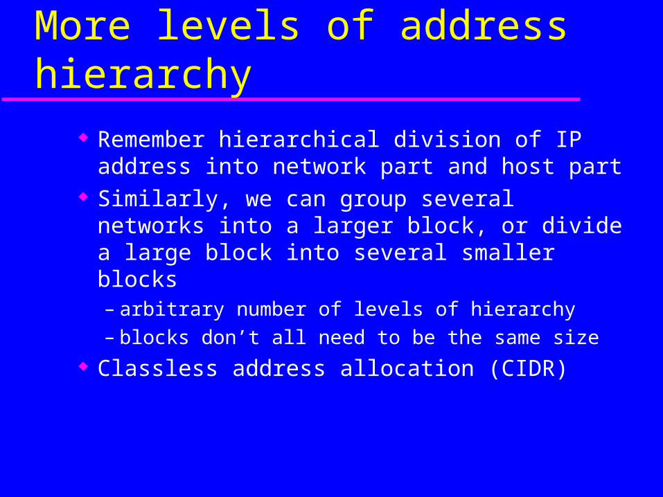
More levels of address hierarchy
Remember hierarchical division of IP address into network part and host part
Similarly, we can group several networks into a larger block, or divide a large block into several smaller blocks– arbitrary number of levels of hierarchy– blocks don’t all need to be the same size
Classless address allocation (CIDR)
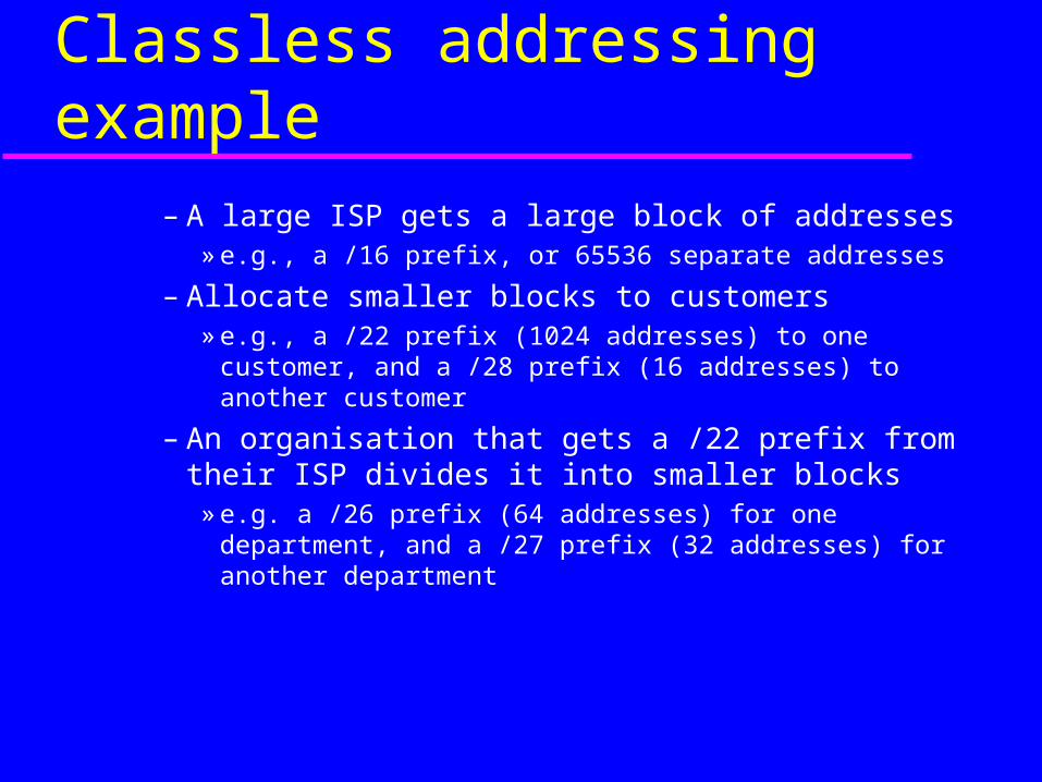
Classless addressing example
– A large ISP gets a large block of addresses» e.g., a /16 prefix, or 65536 separate addresses
– Allocate smaller blocks to customers» e.g., a /22 prefix (1024 addresses) to one customer,
and a /28 prefix (16 addresses) to another customer
– An organisation that gets a /22 prefix from their ISP divides it into smaller blocks
» e.g. a /26 prefix (64 addresses) for one department, and a /27 prefix (32 addresses) for another department
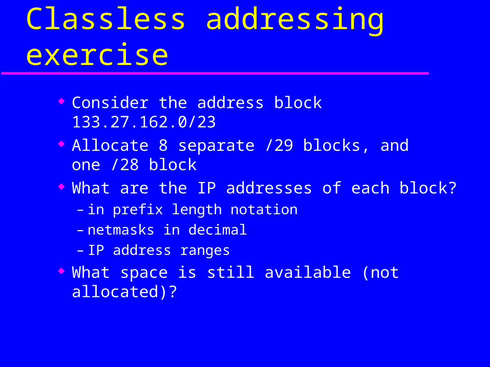
Classless addressing exercise
Consider the address block 133.27.162.0/23 Allocate 8 separate /29 blocks, and one /28
block What are the IP addresses of each block?
– in prefix length notation– netmasks in decimal– IP address ranges
What space is still available (not allocated)?


![[MS-PPPI]: PPP Over IrDA Dialup Protocol...[MS-PPPI]: PPP Over IrDA Dialup Protocol Intellectual Property Rights Notice for Open Specifications Documentation](https://img.pdfslide.us/doc/110x75/6074cab2a6004b4394326229/ms-pppi-ppp-over-irda-dialup-protocol-ms-pppi-ppp-over-irda-dialup-protocol.jpg)


![[MS-PPPI]: PPP Over IrDA Dialup Protocol](https://img.pdfslide.us/doc/110x75/61a409ba0dc068626e4d892d/ms-pppi-ppp-over-irda-dialup-protocol.jpg)