Embed Size (px)
Citation preview
1
Internet2 DCN and Ethernet over SONET
Joint Techs 2008 TutorialJohn S. Graham
2
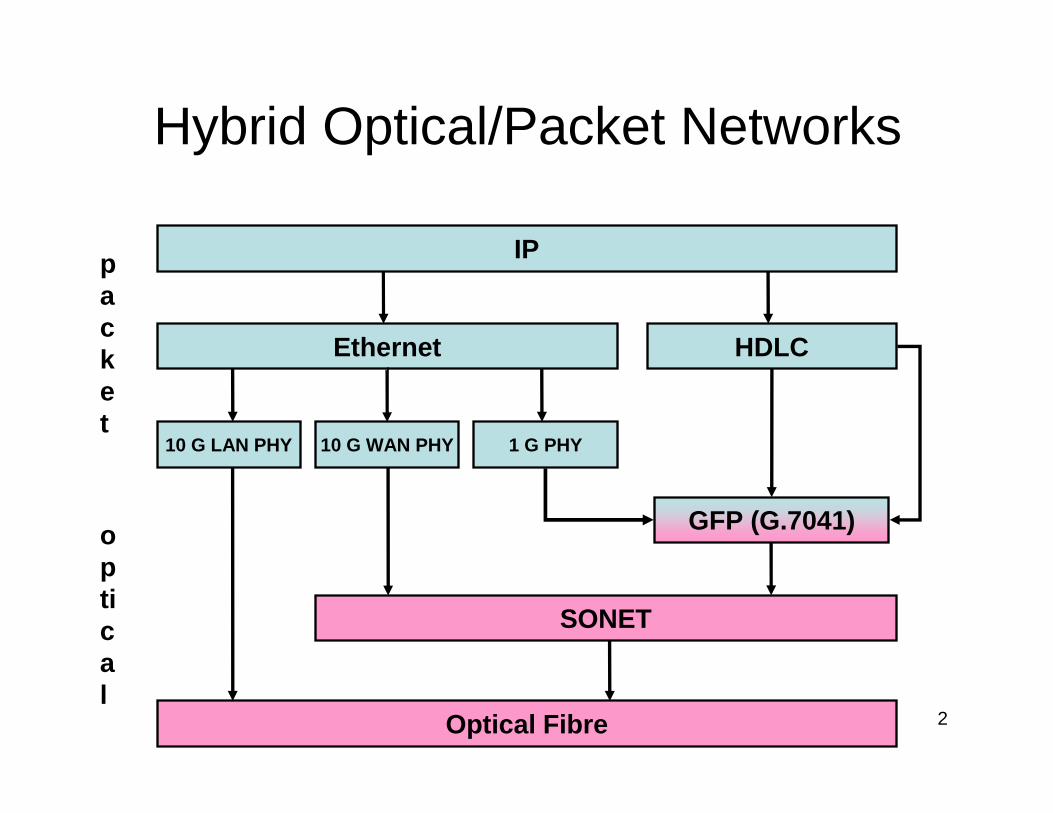
Hybrid Optical/Packet Networks
IP
Ethernet HDLC
10 G LAN PHY 10 G WAN PHY 1 G PHY
SONET
Optical Fibre
GFP (G.7041)
packet
optical
3
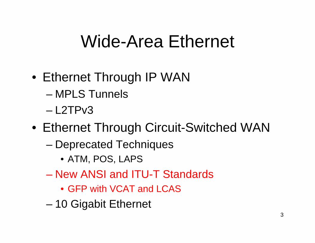
Wide-Area Ethernet
• Ethernet Through IP WAN– MPLS Tunnels
– L2TPv3
• Ethernet Through Circuit-Switched WAN– Deprecated Techniques
• ATM, POS, LAPS
– New ANSI and ITU-T Standards• GFP with VCAT and LCAS
– 10 Gigabit Ethernet
4
SUNN2
1 SALT9 1 DENV9
2
1
ALBU1
2
ELPA10
2
1LOSA1
2
9
KANS9
2
1
HOUS9
2
1 BATO2 1 JACK9
1
NASH
1
9
LOUI
1
2
INDI
1
2
CHIC9
2
1 CLEV9
2
1
PITT9
1 WASH17
9
ATLA1
9
17
PHIL
9
1
1
NEWY1
9BOST 1
22
2
2
2
2rtr.salt:ge-0/1/0
UNM
U of Memphis
USF
UNL
rtr.atla:so-2/1/0
rtr.atla:so-2/0/0
rtr.wash:ge-3/2/0
3 ���� Indiana
3 ���� Drexel
3 ���� PSC
NOX
OSCnet3 ���� PAIX
MAX
MERITESNet
ESNet
3 ���� NYSERNet
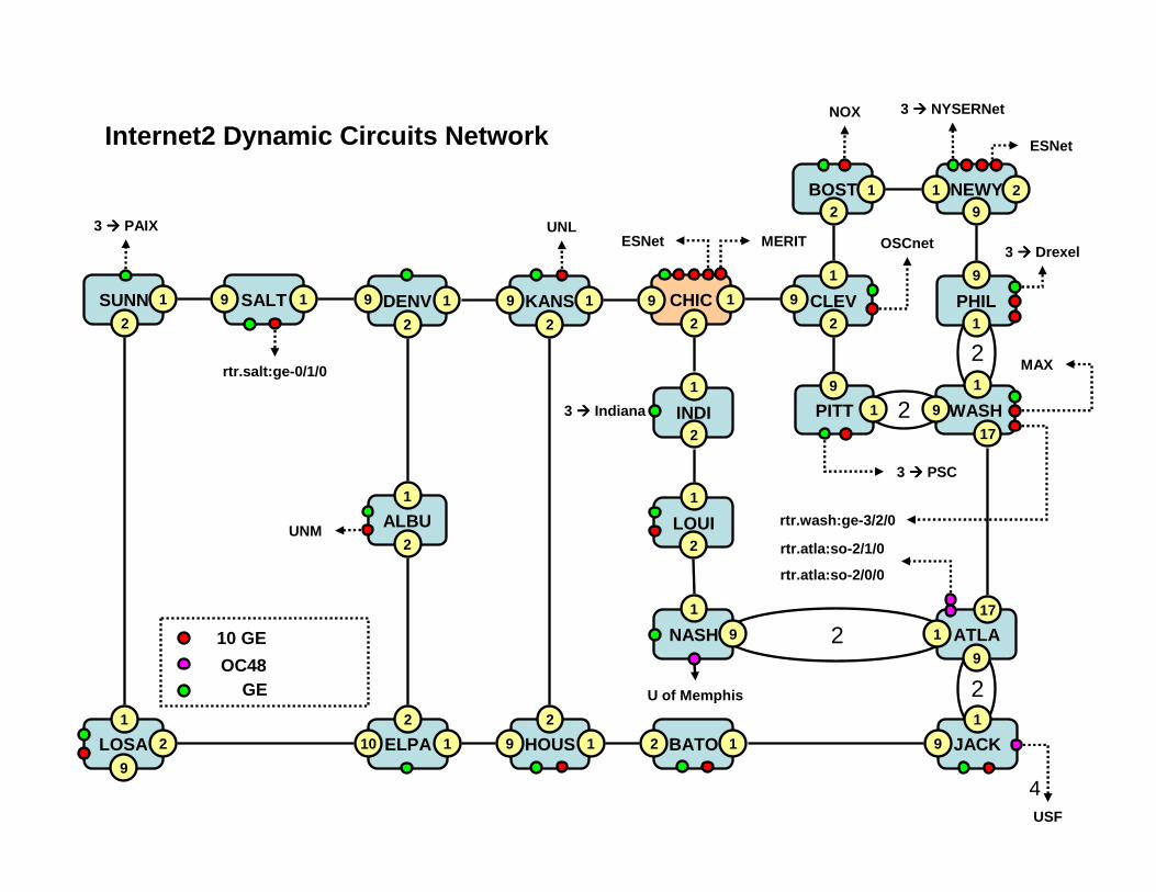
Internet2 Dynamic Circuits Network
10 GE
GEOC48
5
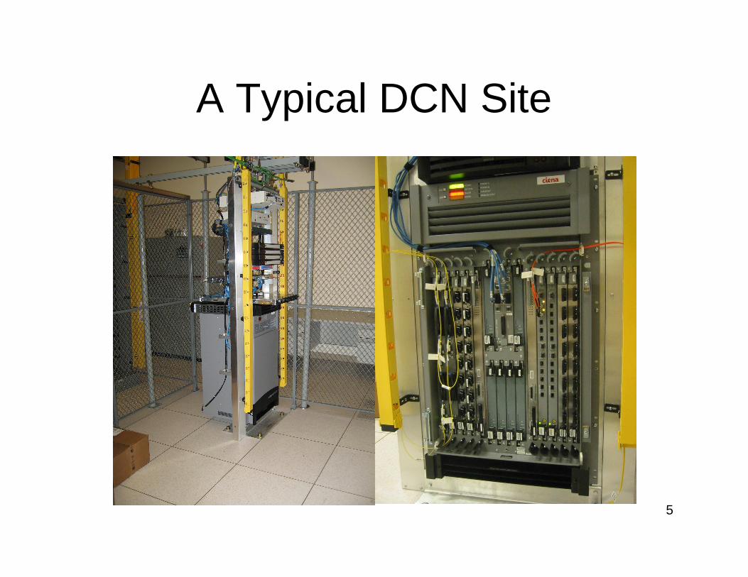
A Typical DCN Site
6
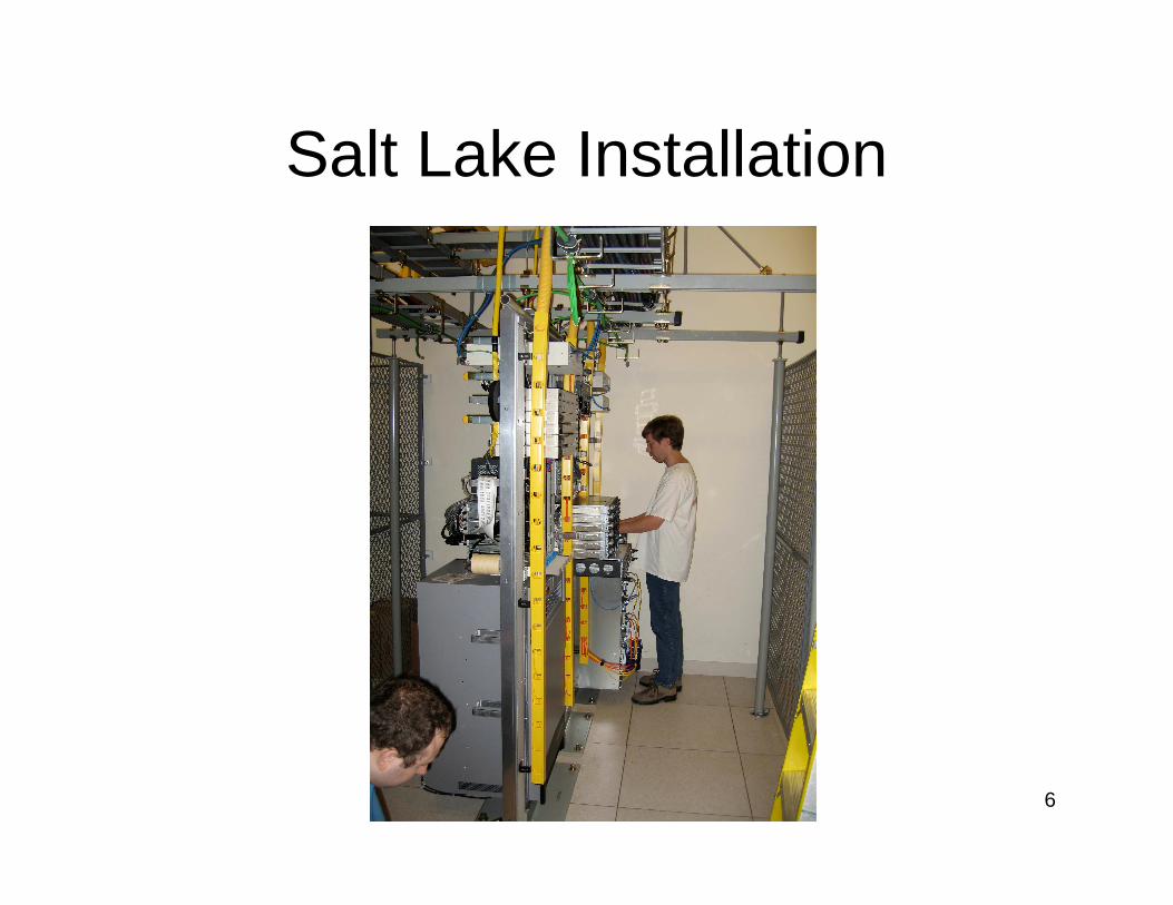
Salt Lake Installation
7
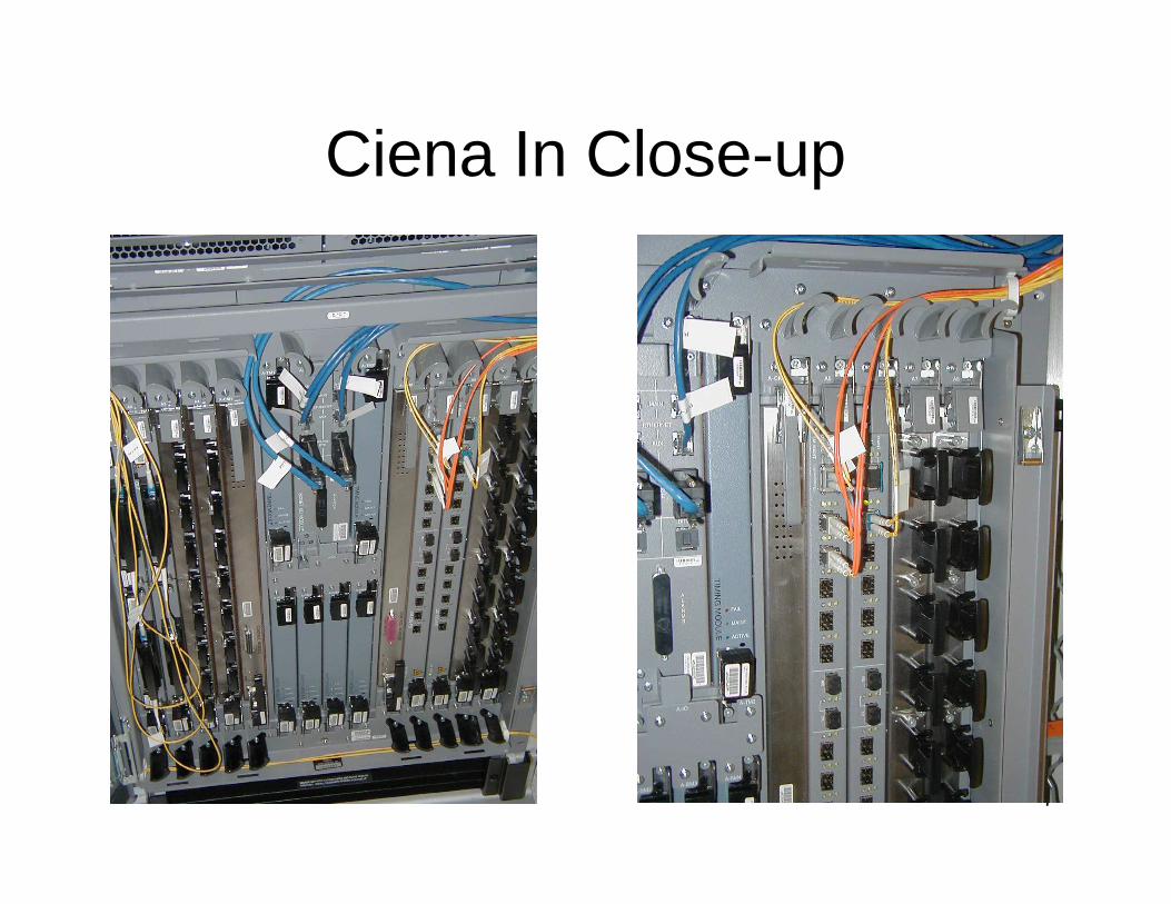
Ciena In Close-up
8
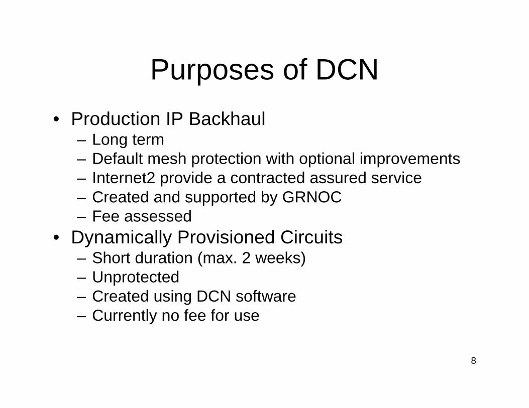
Purposes of DCN
• Production IP Backhaul– Long term– Default mesh protection with optional improvements– Internet2 provide a contracted assured service– Created and supported by GRNOC– Fee assessed
• Dynamically Provisioned Circuits– Short duration (max. 2 weeks)– Unprotected– Created using DCN software– Currently no fee for use
9
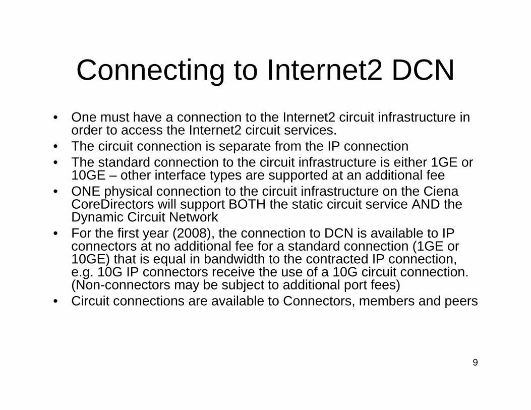
Connecting to Internet2 DCN• One must have a connection to the Internet2 circuit infrastructure in
order to access the Internet2 circuit services. • The circuit connection is separate from the IP connection • The standard connection to the circuit infrastructure is either 1GE or
10GE – other interface types are supported at an additional fee• ONE physical connection to the circuit infrastructure on the Ciena
CoreDirectors will support BOTH the static circuit service AND the Dynamic Circuit Network
• For the first year (2008), the connection to DCN is available to IP connectors at no additional fee for a standard connection (1GE or 10GE) that is equal in bandwidth to the contracted IP connection, e.g. 10G IP connectors receive the use of a 10G circuit connection. (Non-connectors may be subject to additional port fees)
• Circuit connections are available to Connectors, members and peers
10
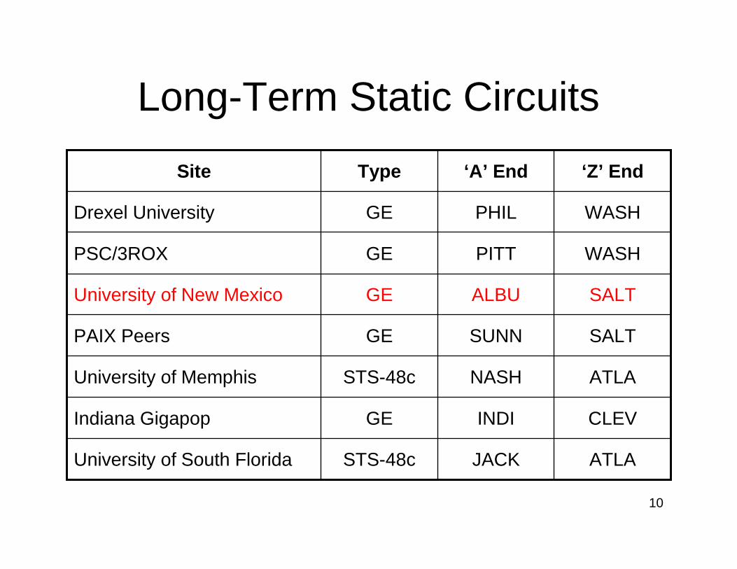
Long-Term Static Circuits
CLEVINDIGEIndiana Gigapop
STS-48c
STS-48c
GE
GE
GE
GE
Type
ATLAJACKUniversity of South Florida
ATLANASHUniversity of Memphis
SALTSUNNPAIX Peers
SALTALBUUniversity of New Mexico
WASHPITTPSC/3ROX
WASHPHILDrexel University
‘Z’ End‘A’ EndSite
11
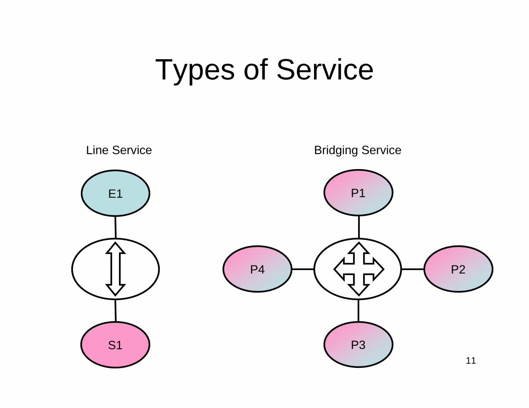
Types of Service
E1
S1
P2
P1
P4
P3
Line Service Bridging Service
12
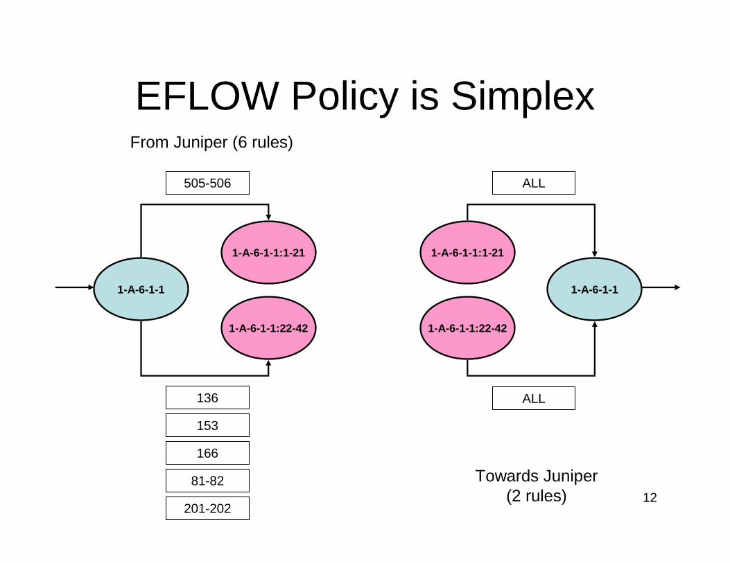
EFLOW Policy is Simplex
1-A-6-1-1
1-A-6-1-1:22-42
1-A-6-1-1:1-21
1-A-6-1-1:22-42
1-A-6-1-1:1-21
1-A-6-1-1
From Juniper (6 rules)
Towards Juniper (2 rules)
505-506 ALL
ALL136
153
166
81-82
201-202
13
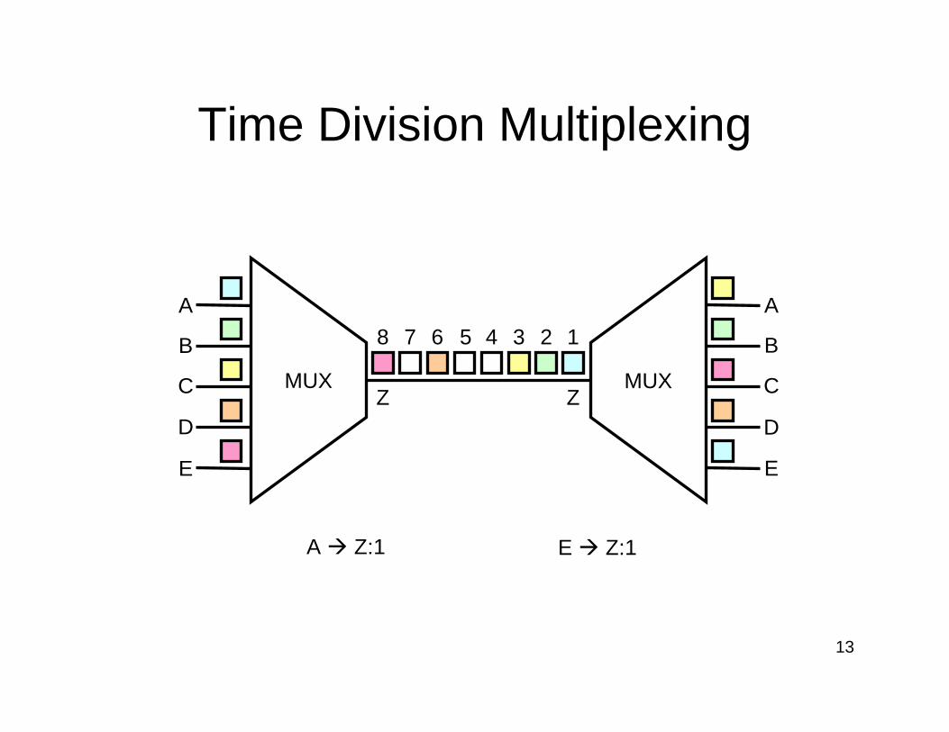
Time Division Multiplexing
A � Z:1 E � Z:1
E
D
C
B
A
MUX
E
D
C
B
A
MUXZ
13458
Z
7 6 2
14
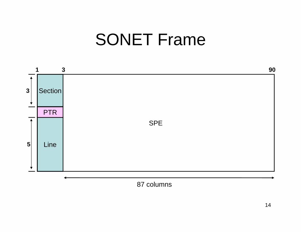
SONET Frame
Section
Line
PTR
SPE
3
5
87 columns
9031
15
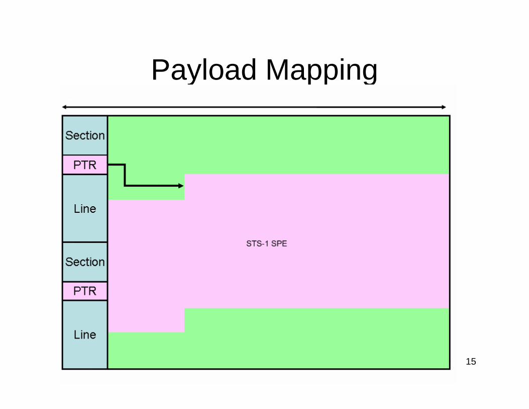
Payload Mapping
16
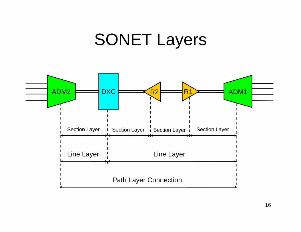
SONET Layers
Section LayerSection Layer
R1ADM2 DXC ADM1
Path Layer Connection
Line LayerLine Layer
Section Layer Section Layer
R2
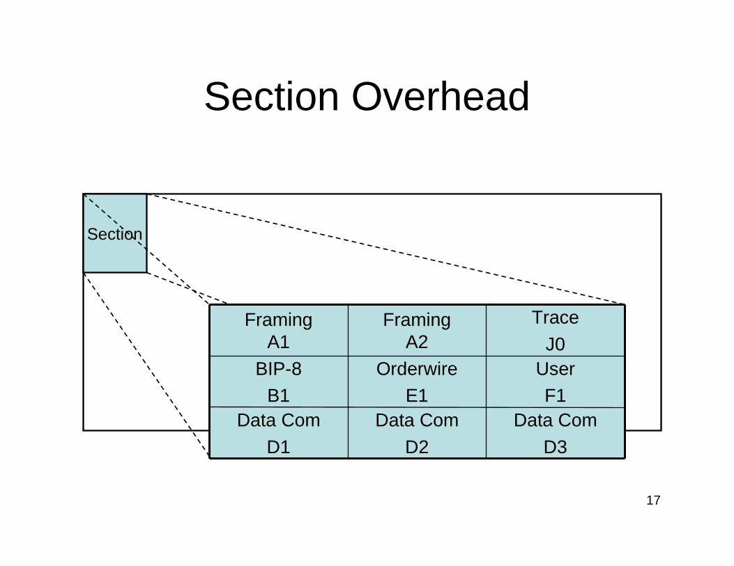
17
Section Overhead
Data Com
D3
Data Com
D2
Data Com
D1
UserF1
OrderwireE1
BIP-8B1
Trace
J0Framing
A2Framing
A1
Section
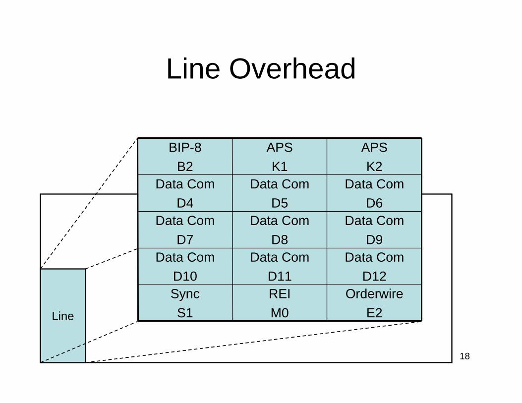
18
Line Overhead
Line
Orderwire
E2
REI
M0
Sync
S1
Data ComD12
Data ComD11
Data ComD10
Data Com
D9
Data Com
D8
Data Com
D7
Data ComD6
Data ComD5
Data ComD4
APS
K2
APS
K1
BIP-8
B2
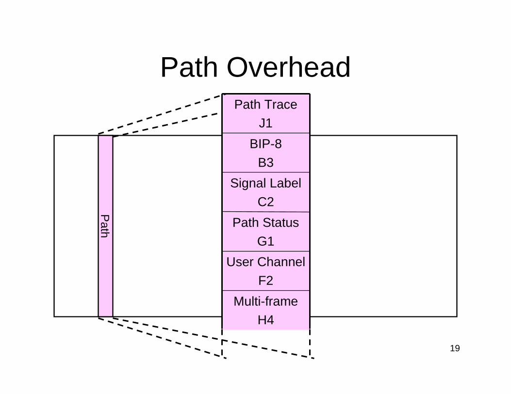
19
Path Overhead
Path
Multi-frameH4
User Channel
F2
Path Status
G1
Signal Label
C2
BIP-8
B3
Path TraceJ1
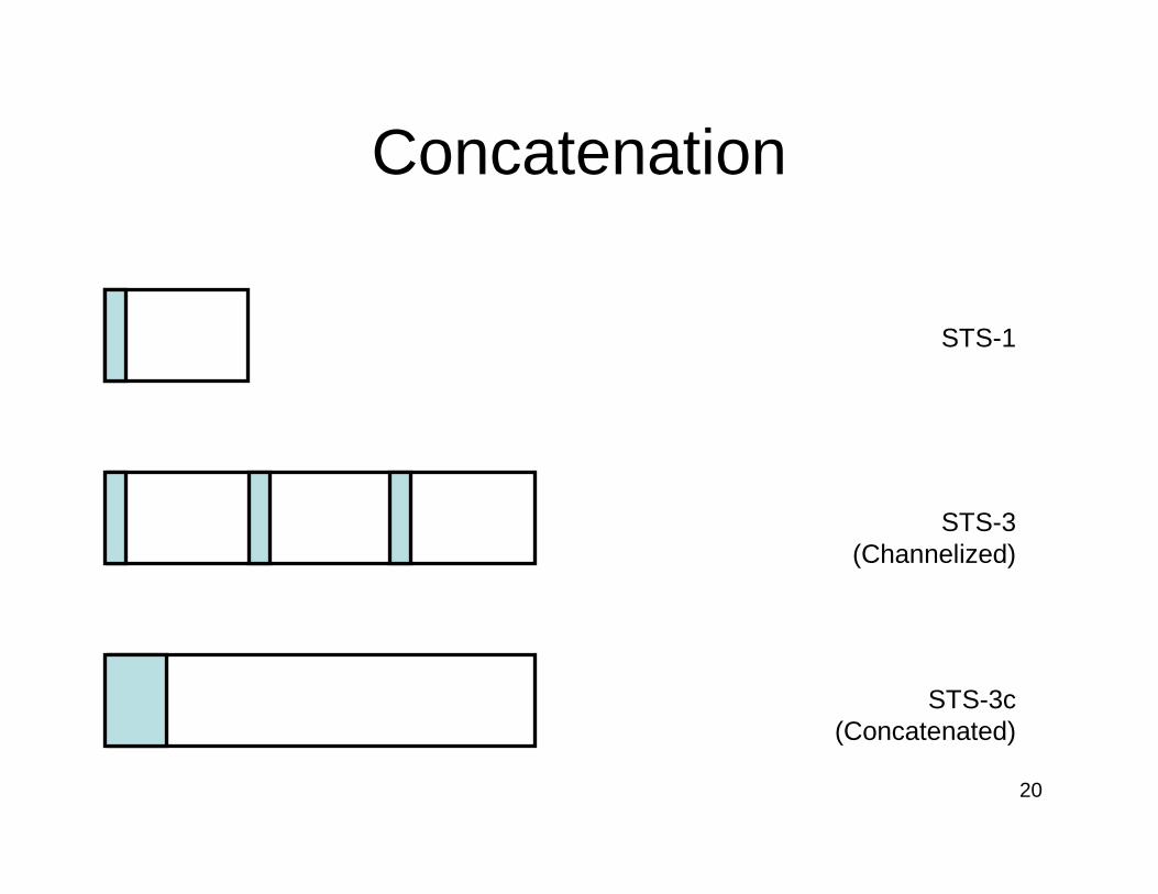
20
Concatenation
STS-1
STS-3 (Channelized)
STS-3c (Concatenated)
21
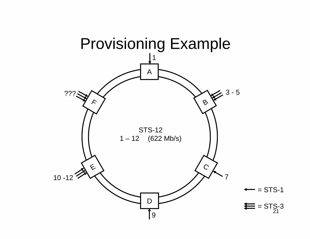
Provisioning Example
A
D
B
E C
F3 - 5
7
9
10 -12
1
???
STS-121 – 12 (622 Mb/s)
= STS-1
= STS-3
22
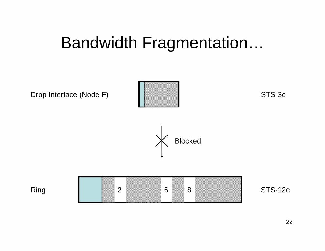
Bandwidth Fragmentation…
Drop Interface (Node F)
Ring 2 6 8
Blocked!
STS-3c
STS-12c
23
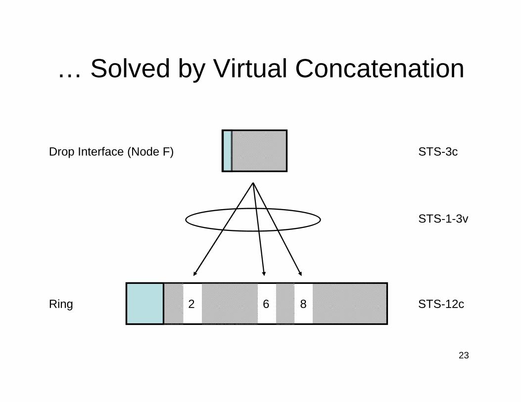
… Solved by Virtual Concatenation
Drop Interface (Node F)
Ring 2 6 8
STS-3c
STS-12c
STS-1-3v
24
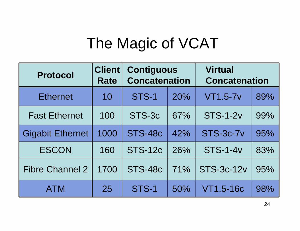
The Magic of VCAT
95%STS-3c-12v71%STS-48c1700Fibre Channel 2
89%VT1.5-7v20%STS-110Ethernet
95%STS-3c-7v42%STS-48c1000Gigabit Ethernet
98%VT1.5-16c50%STS-125ATM
83%STS-1-4v26%STS-12c160ESCON
99%STS-1-2v67%STS-3c100Fast Ethernet
Virtual Concatenation
Contiguous Concatenation
Client Rate
Protocol
25
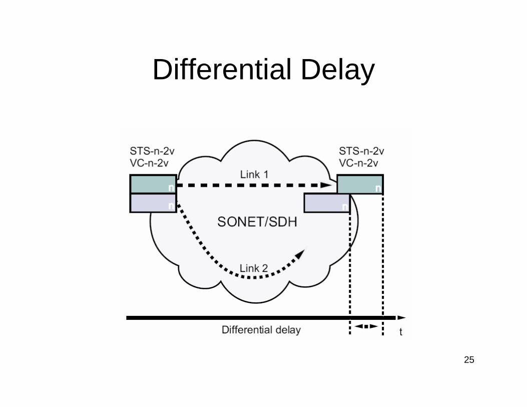
Differential Delay
26
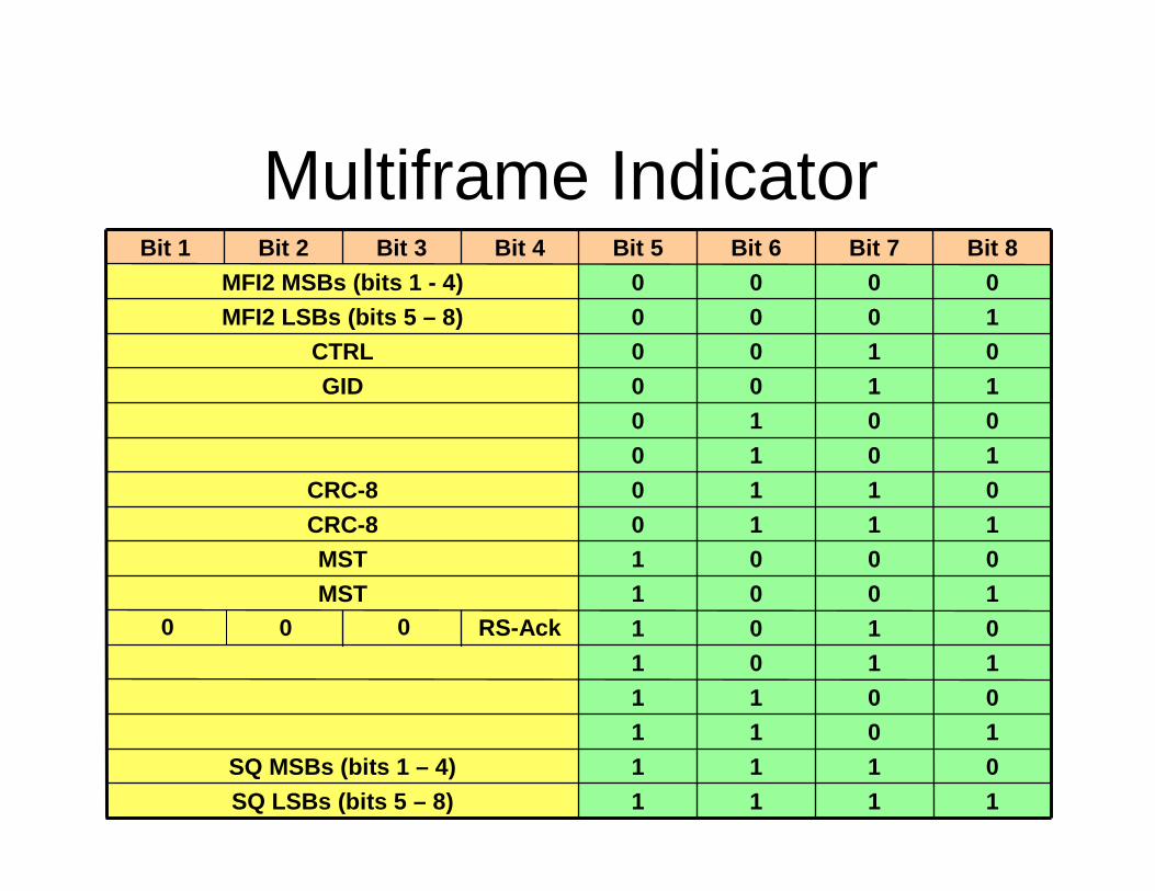
Multiframe Indicator
0 0 0 RS-Ack
0110CRC-8
1111SQ LSBs (bits 5 – 8)
0111SQ MSBs (bits 1 – 4)
10110011
1101
0101
1001MST
0001MST1110CRC-8
1010
0010
1100GID
0100CTRL1000MFI2 LSBs (bits 5 – 8)
0000MFI2 MSBs (bits 1 - 4)
Bit 8Bit 7Bit 6Bit 5Bit 4Bit 3Bit 2Bit 1
27
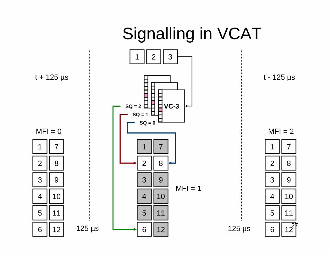
Signalling in VCAT
VC-3
SQ = 0
SQ = 2
SQ = 1
125 µs
1
2
3
4
5
7
8
9
10
126
11
MFI = 1
MFI = 0
1
2
3
4
5
7
8
9
10
126
11
1 2 3
125 µs
1
2
3
4
5
7
8
9
10
126
11
MFI = 2
t + 125 µs t - 125 µs
28
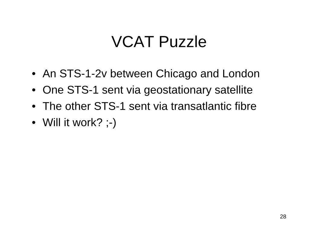
VCAT Puzzle
• An STS-1-2v between Chicago and London
• One STS-1 sent via geostationary satellite
• The other STS-1 sent via transatlantic fibre
• Will it work? ;-)
29
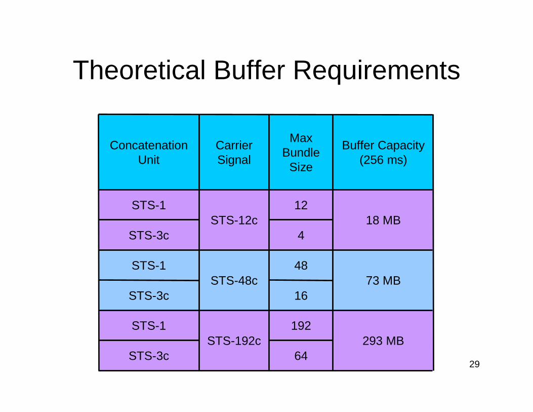
Theoretical Buffer Requirements
64STS-3c293 MB
192STS-192c
STS-1
16STS-3c73 MB
48STS-48c
STS-1
4STS-3c18 MB
12STS-12c
STS-1
Buffer Capacity (256 ms)
Max Bundle
Size
Carrier Signal
Concatenation Unit
30
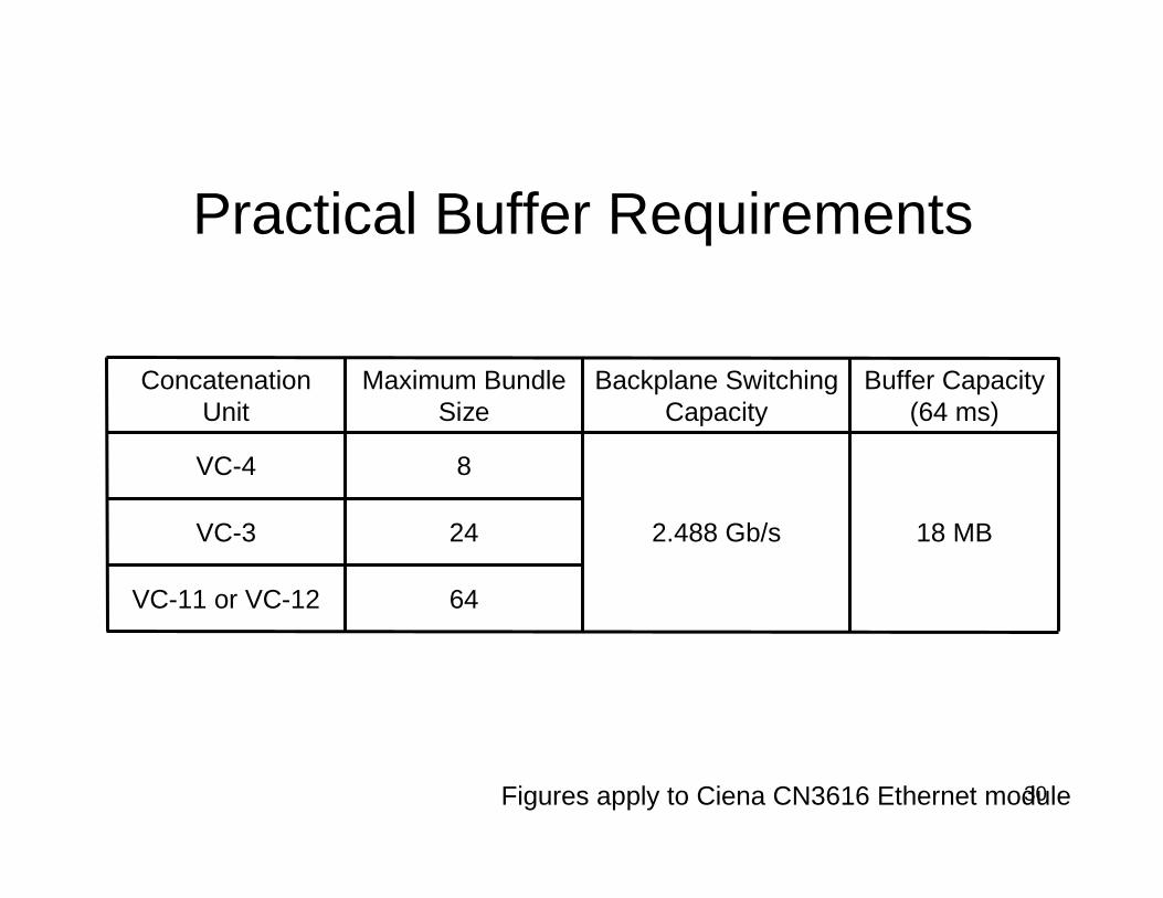
Practical Buffer Requirements
64VC-11 or VC-12
24VC-3 18 MB2.488 Gb/s
8VC-4
Buffer Capacity (64 ms)
Backplane Switching Capacity
Maximum Bundle Size
Concatenation Unit
Figures apply to Ciena CN3616 Ethernet module
31
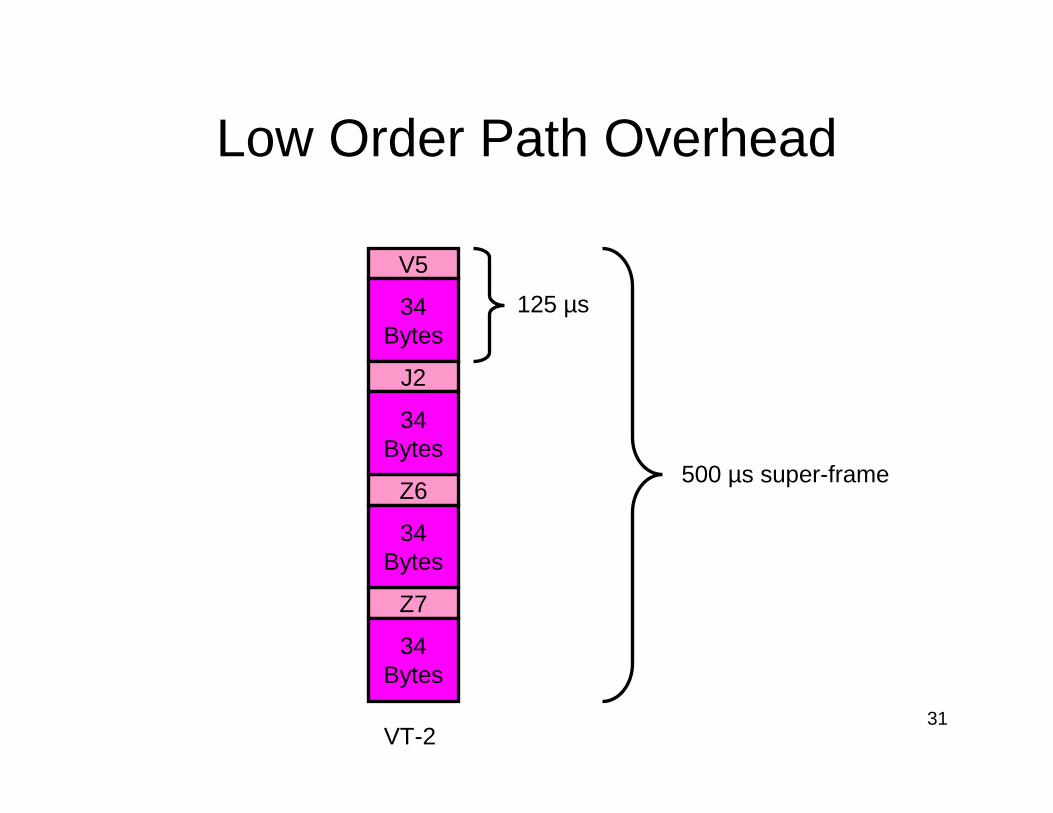
Low Order Path Overhead
V5
34Bytes
J2
Z6
Z7
34Bytes
34Bytes
34Bytes
125 µs
500 µs super-frame
VT-2

32
Low Order VCAT
MFI SQ CTRL
6 - 11
32 × 500 µs = 16 ms
Z7 Bit #2
Z7 Bit #1
1 - 5
0x0 MST CRC-3
Alignment Extended Signal Label 0
12 - 15
Reserved
22 - 29
GID RS-Ack
16 - 21
33
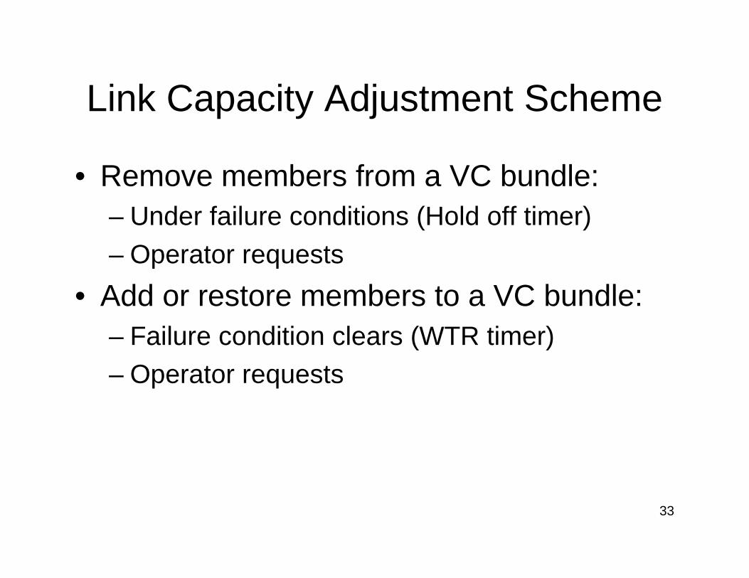
Link Capacity Adjustment Scheme
• Remove members from a VC bundle:– Under failure conditions (Hold off timer)
– Operator requests
• Add or restore members to a VC bundle:– Failure condition clears (WTR timer)– Operator requests
34
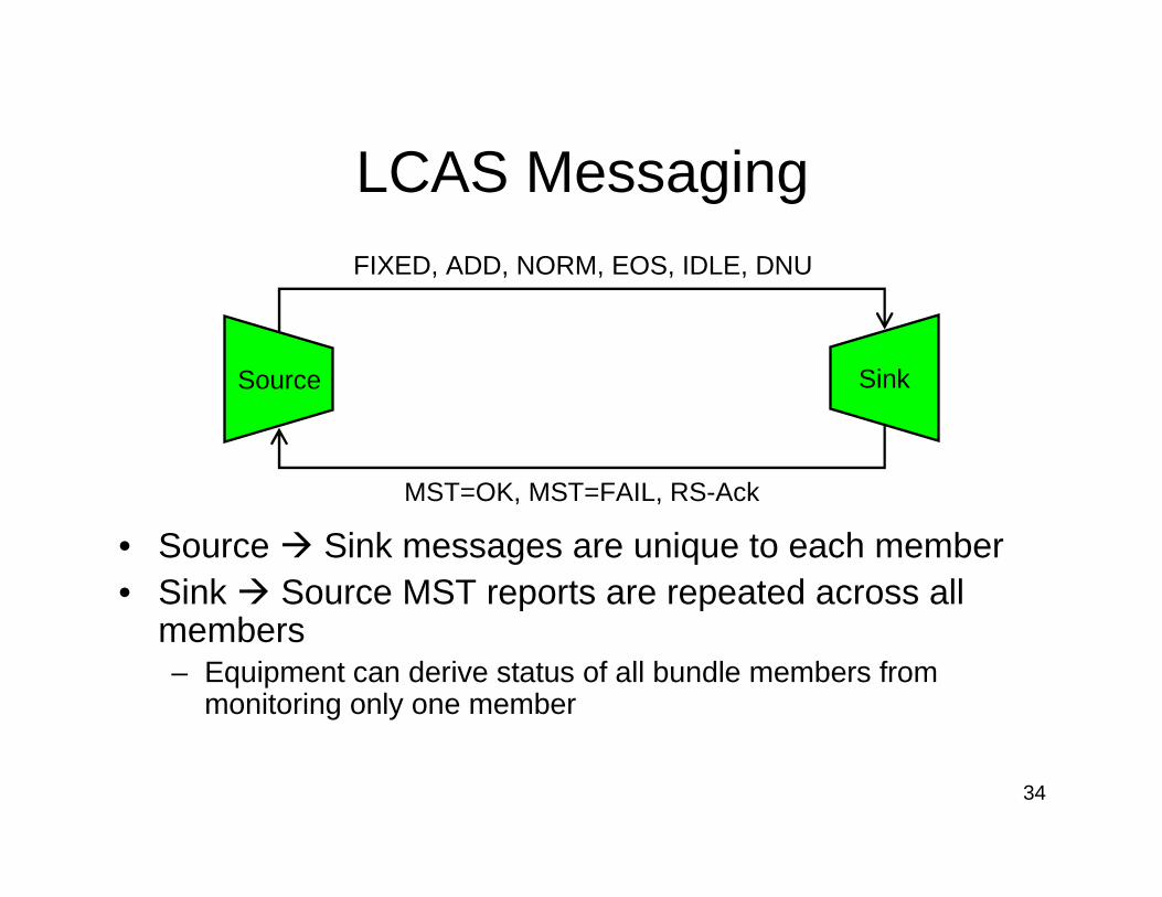
LCAS Messaging
Source Sink
FIXED, ADD, NORM, EOS, IDLE, DNU
MST=OK, MST=FAIL, RS-Ack
• Source � Sink messages are unique to each member• Sink � Source MST reports are repeated across all
members– Equipment can derive status of all bundle members from
monitoring only one member
35
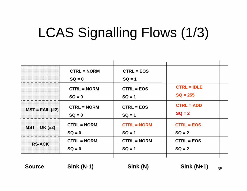
LCAS Signalling Flows (1/3)
CTRL = ADD
SQ = 2
Source Sink (N-1)
CTRL = EOS
SQ = 1
CTRL = NORM
SQ = 0
MST = OK (#2) CTRL = NORM
SQ = 1
CTRL = NORM
SQ = 0
Sink (N) Sink (N+1)
CTRL = NORM
SQ = 0
CTRL = EOS
SQ = 1
CTRL = EOS
SQ = 2
CTRL = IDLE
SQ = 255CTRL = NORM
SQ = 0
CTRL = EOS
SQ = 1
RS-ACKCTRL = NORM
SQ = 1
CTRL = NORM
SQ = 0
CTRL = EOS
SQ = 2
MST = FAIL (#2)
36
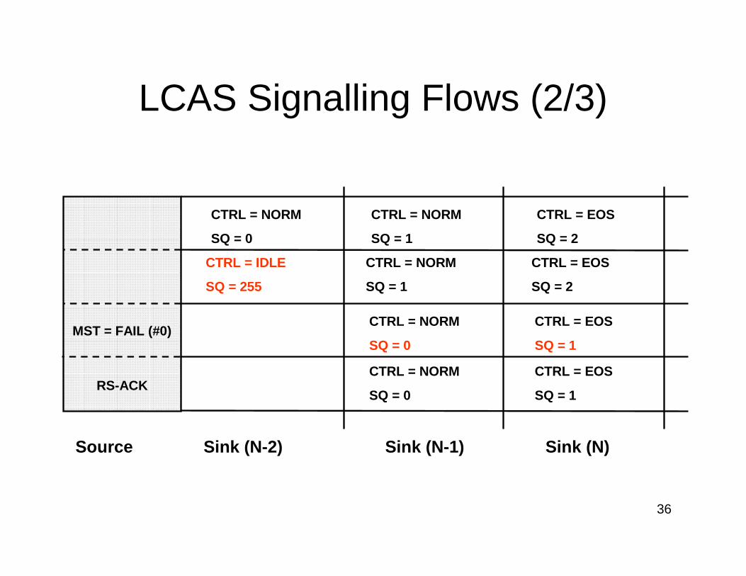
LCAS Signalling Flows (2/3)
CTRL = EOS
SQ = 2
Source Sink (N-2)
CTRL = NORM
SQ = 1
CTRL = IDLE
SQ = 255
CTRL = EOS
SQ = 2
CTRL = NORM
SQ = 1
CTRL = NORM
SQ = 0
MST = FAIL (#0)CTRL = EOS
SQ = 1
CTRL = NORM
SQ = 0
Sink (N-1) Sink (N)
RS-ACKCTRL = EOS
SQ = 1
CTRL = NORM
SQ = 0
37
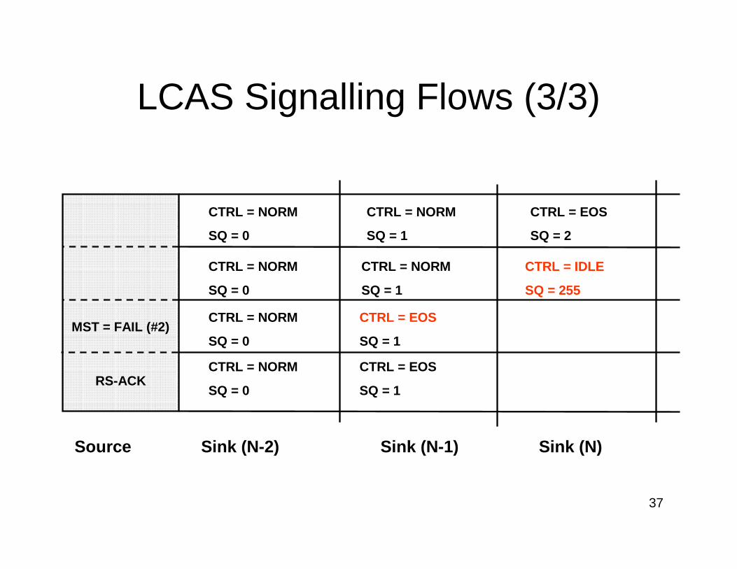
LCAS Signalling Flows (3/3)
CTRL = IDLE
SQ = 255
Source Sink (N-2)
CTRL = NORM
SQ = 1
CTRL = EOS
SQ = 2
CTRL = NORM
SQ = 1
CTRL = NORM
SQ = 0
MST = FAIL (#2)CTRL = EOS
SQ = 1
CTRL = NORM
SQ = 0
Sink (N-1) Sink (N)
RS-ACKCTRL = EOS
SQ = 1
CTRL = NORM
SQ = 0
CTRL = NORM
SQ = 0
38
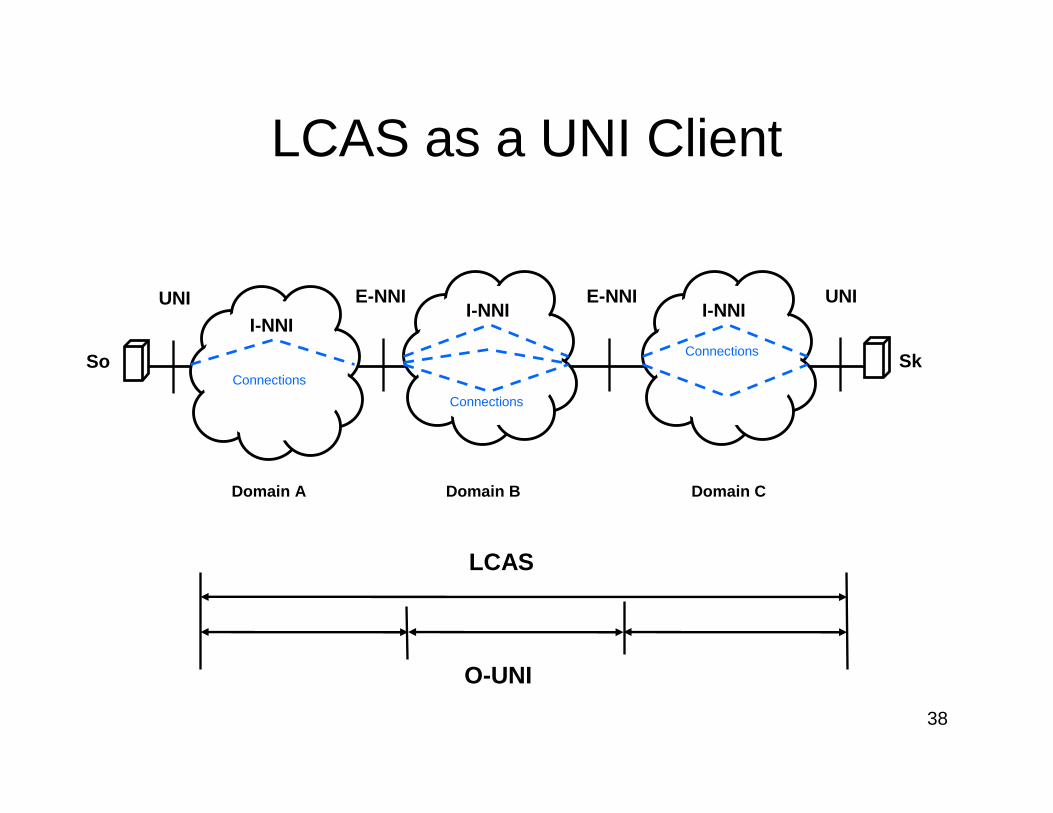
LCAS as a UNI Client
UNI UNIE-NNI E-NNI
Domain A
So SkConnections
Connections
Connections
O-UNI
LCAS
Domain B Domain C
I-NNII-NNI I-NNI
39
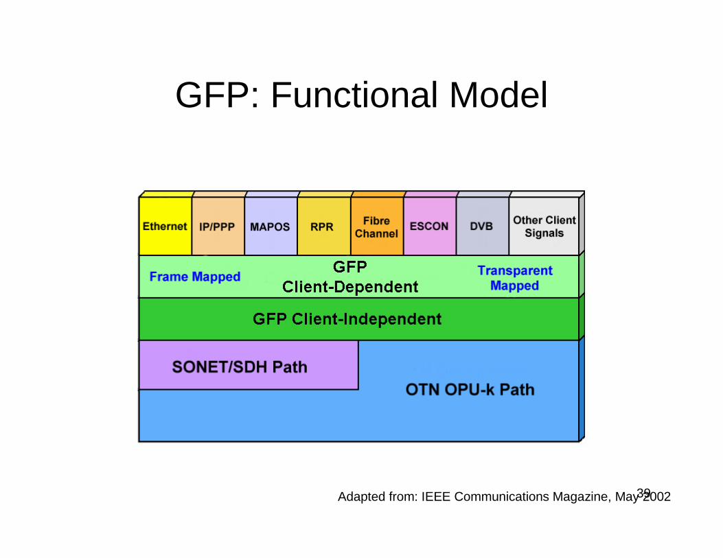
GFP: Functional Model
Adapted from: IEEE Communications Magazine, May 2002
40
Generic Framing Procedure
• ITU-T G.7041 and ANSI T1.105.02• Defines mapping for many types of service
onto SONET/SDH or OTN:– Ethernet, IP/PPP– GbE, Fibre Channel (inc. DVB), FICON etc
• Excellent bandwidth utilization; efficiency tailored to suit different client types
• Simple delineation and robust error control• Extensible
41
Tasks Performed by GFP
• Major– Client frame delineation
– Client payload mapping– Client-to-carrier rate adaptation
• Minor– Limited OA&M (Link Loss Forwarding)
– Optional client frame multiplexing
42
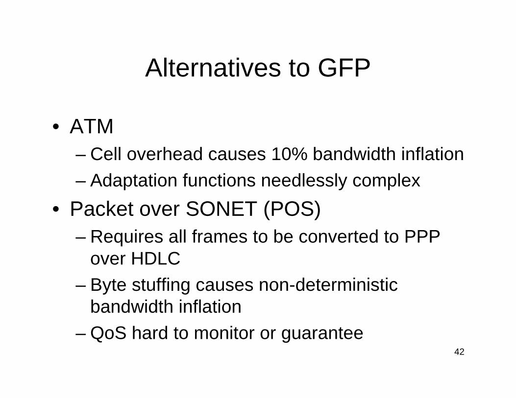
Alternatives to GFP
• ATM– Cell overhead causes 10% bandwidth inflation
– Adaptation functions needlessly complex
• Packet over SONET (POS)– Requires all frames to be converted to PPP
over HDLC– Byte stuffing causes non-deterministic
bandwidth inflation
– QoS hard to monitor or guarantee
43
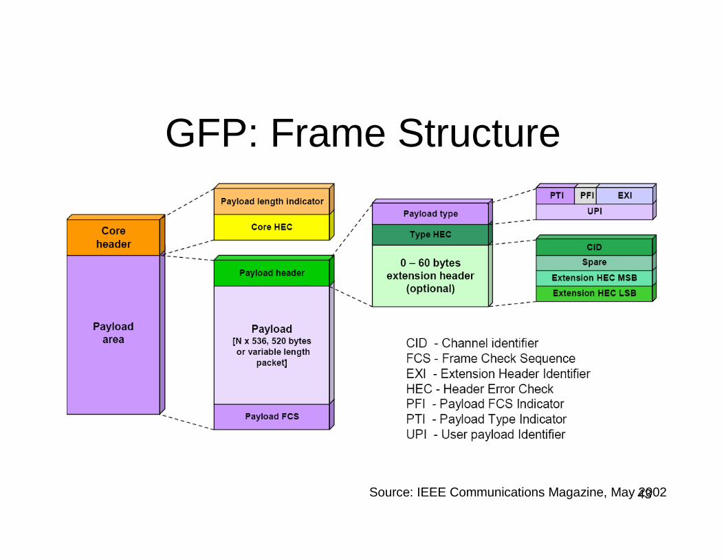
GFP: Frame Structure
Source: IEEE Communications Magazine, May 2002
44
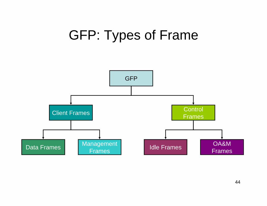
GFP: Types of Frame
GFP
Client FramesControl Frames
Data FramesManagement
FramesIdle Frames
OA&M Frames
45
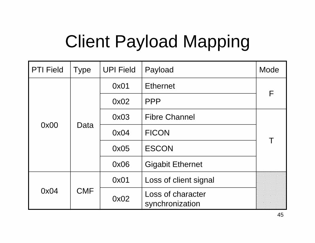
Client Payload Mapping
Loss of character synchronization
0x02
Loss of client signal0x01CMF0x04
Gigabit Ethernet0x06
ESCON0x05
FICON0x04T
Fibre Channel0x03
PPP0x02F
Ethernet0x01
Data0x00
ModePayloadUPI FieldTypePTI Field
46
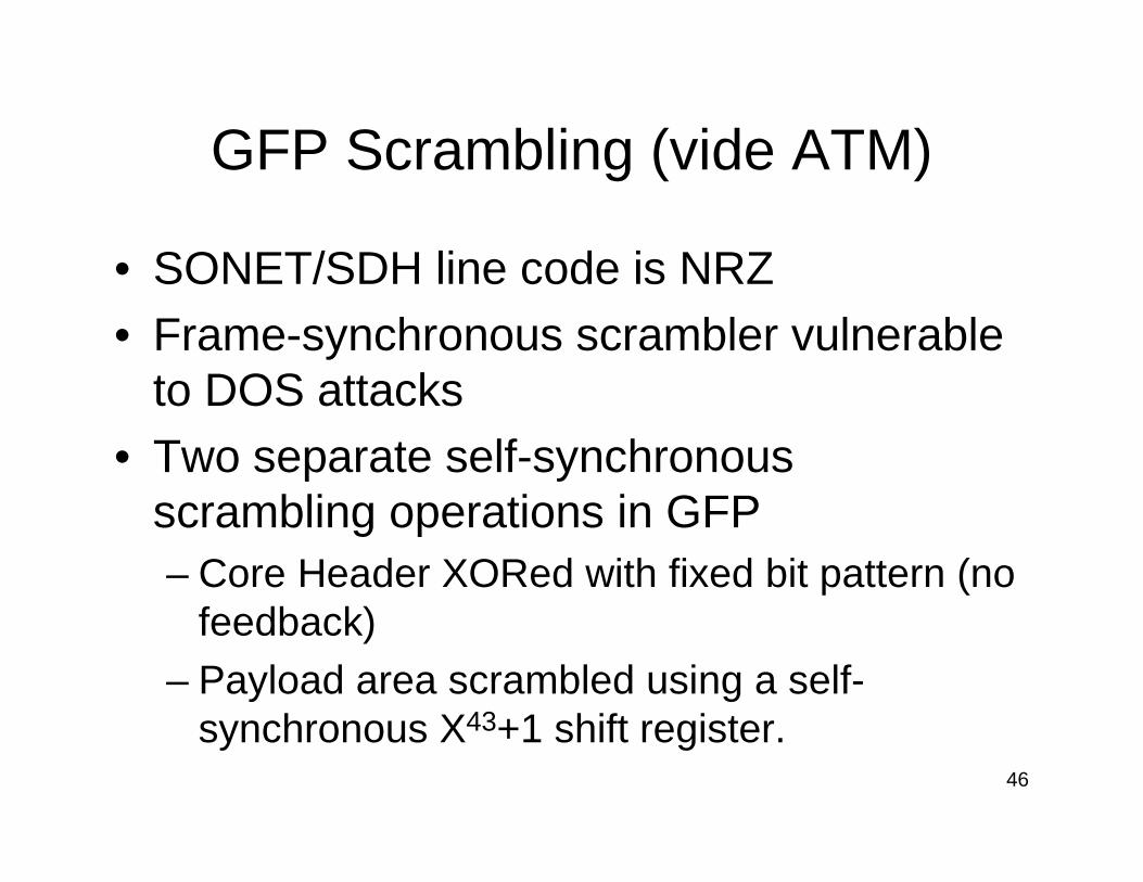
GFP Scrambling (vide ATM)
• SONET/SDH line code is NRZ• Frame-synchronous scrambler vulnerable
to DOS attacks• Two separate self-synchronous
scrambling operations in GFP– Core Header XORed with fixed bit pattern (no
feedback)– Payload area scrambled using a self-
synchronous X43+1 shift register.
47
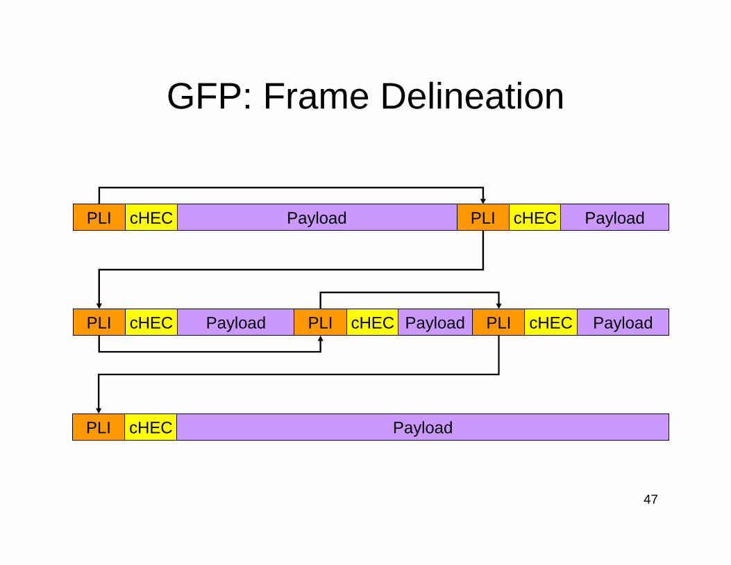
GFP: Frame Delineation
PayloadPLI cHEC PLI cHEC Payload
Payload PLI cHEC PayloadPLI cHEC PayloadPLI cHEC
PayloadPLI cHEC
48
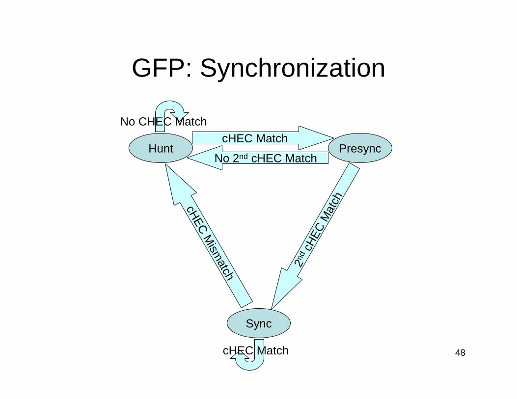
GFP: Synchronization
Hunt Presync
SynccH
EC M
ismatch
2nd
cHE
C M
atch
cHEC Match
No 2nd cHEC Match
cHEC Match
No CHEC Match
49
GFP-F 802.3 MAC Awareness
• At Source:– Remove preamble & SFD (8 Bytes)
– Remove IPG (12 Bytes)
• At Sink:– Regenerate valid frame– Insert minimum IPG
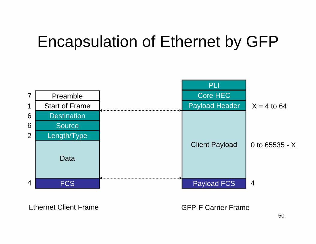
50
Encapsulation of Ethernet by GFP
Data
FCS
Length/TypeSource
DestinationStart of Frame
Preamble71662
4
Client Payload
Payload FCS
Payload HeaderCore HEC
PLI
4
X = 4 to 64
0 to 65535 - X
Ethernet Client Frame GFP-F Carrier Frame
51
GFP-F Summary
�Minimal overhead�Transport of client PDUs in native format�Designed for optimized processing in
hardware�Easy aggregation of frames from multiple
client and multiple protocols into shared bandwidth channels
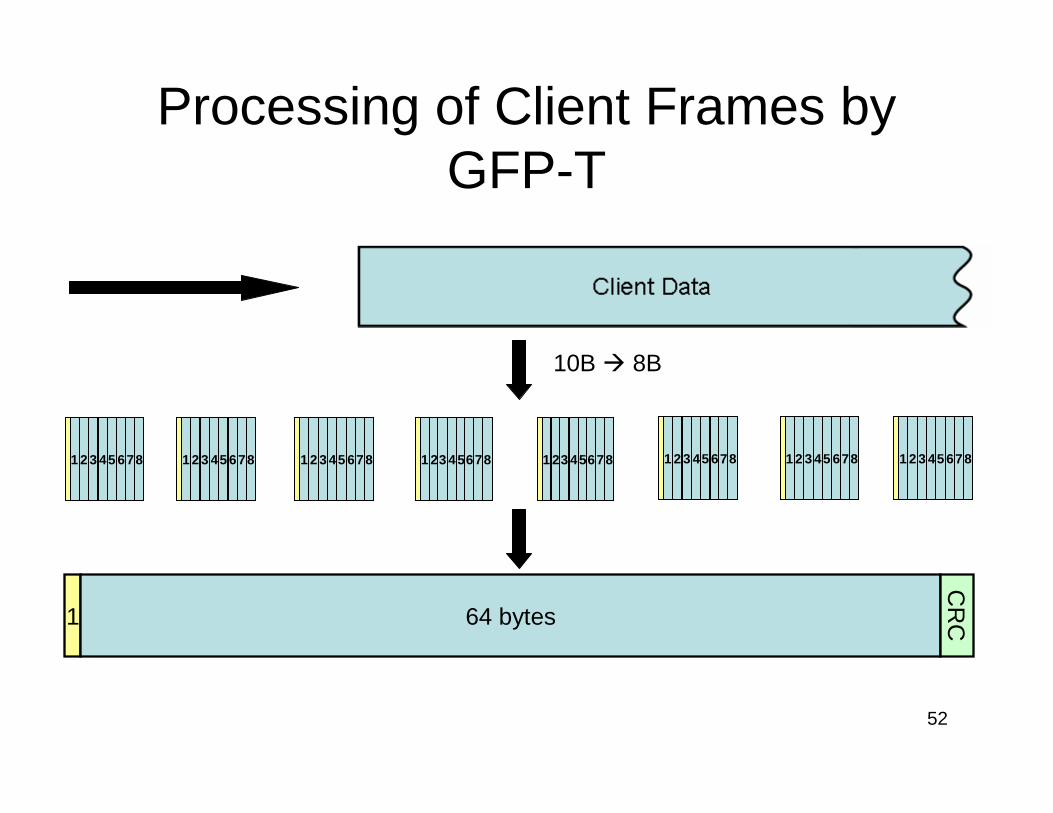
52
Processing of Client Frames by GFP-T
1 2 3 45 678 1 2 3 45 678 1 23 45678 1 23 45678 1 2 3 45 678 1 2 3 45 678 1 2 3 45 6781 2 3 45 678
1 64 bytes
CR
C
10B � 8B
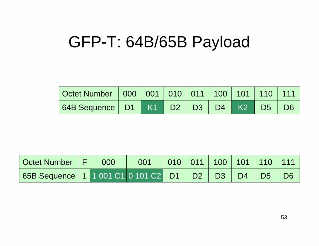
53
GFP-T: 64B/65B Payload
D1 K1 D2 D3 K2D4 D5 D6
000 001 010 011 101 110 111F
65B Sequence 1 001 C1 D2 D3 D4 D5 D61 0 101 C2 D1
100Octet Number
64B Sequence
000 001 010 011 100 101 110 111Octet Number
54
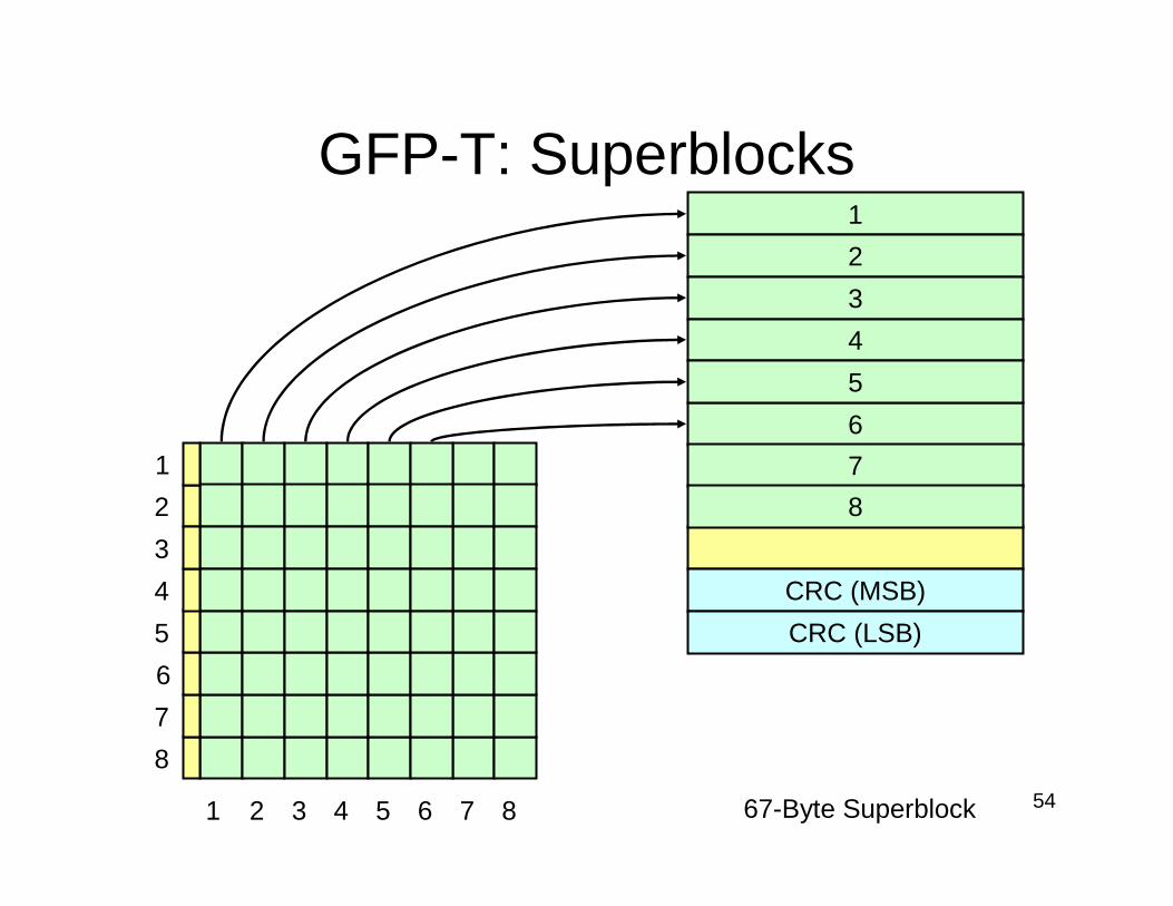
GFP-T: Superblocks
21 3 4 5 6 7 8
2
1
3
4
5
6
7
8
67-Byte Superblock
1
2
3
4
6
5
CRC (MSB)
CRC (LSB)
7
8
55
Why Append a CRC?
• The 8B/10B � 64B/65B remapping process causes loss of redundancy.
• Four sources of error:– Leading flag bit is errored– Error affects ‘Last control-code’ indicator
– Control-code location address received in error
– Error causes 4-bit control code to be modified
56
Pros and Cons: GFP-F
�Higher bandwidth efficiency
�Higher Latency�More buffer memory required�Core header fields must be calculated
57
Pros and Cons: GFP-T
�Low latency�Ingress core header fields need not be
calculated
�Less bandwidth efficient�More logic required
58
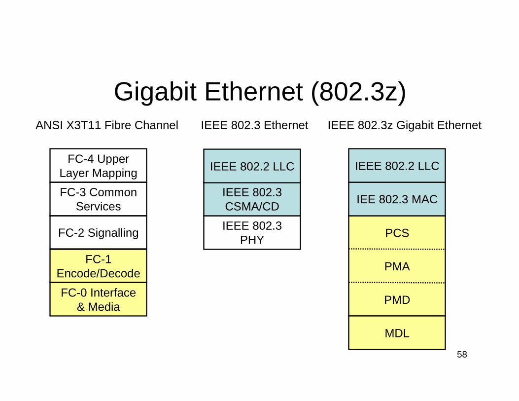
Gigabit Ethernet (802.3z)
FC-0 Interface & Media
FC-1 Encode/Decode
FC-2 Signalling
FC-3 Common Services
FC-4 Upper Layer Mapping
IEEE 802.3 PHY
IEEE 802.3 CSMA/CD
IEEE 802.2 LLC
ANSI X3T11 Fibre Channel IEEE 802.3 Ethernet IEEE 802.3z Gigabit Ethernet
MDL
IEE 802.3 MAC
IEEE 802.2 LLC
PMD
PMA
PCS
59
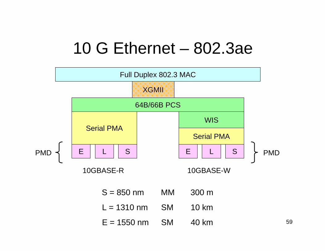
10 G Ethernet – 802.3ae
10GBASE-R 10GBASE-W
S = 850 nm MM 300 m
L = 1310 nm SM 10 km
E = 1550 nm SM 40 km
Full Duplex 802.3 MAC
64B/66B PCS
Serial PMASerial PMA
WIS
E L SE L S
XGMII
PMDPMD
60
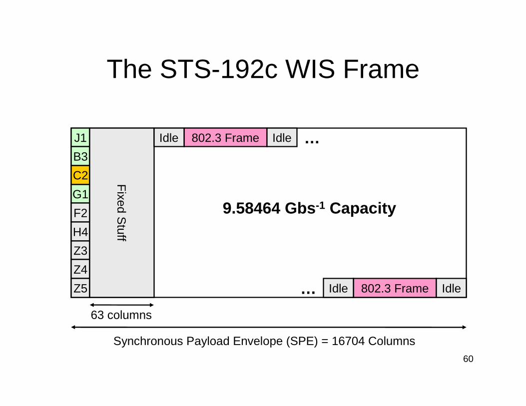
The STS-192c WIS Frame
J1
B3
C2
G1
F2
H4
Z3
Z4
Z5
Fixed S
tuff
Synchronous Payload Envelope (SPE) = 16704 Columns
63 columns
9.58464 Gbs -1 Capacity
802.3 FrameIdle Idle
802.3 FrameIdle Idle
…
…
61
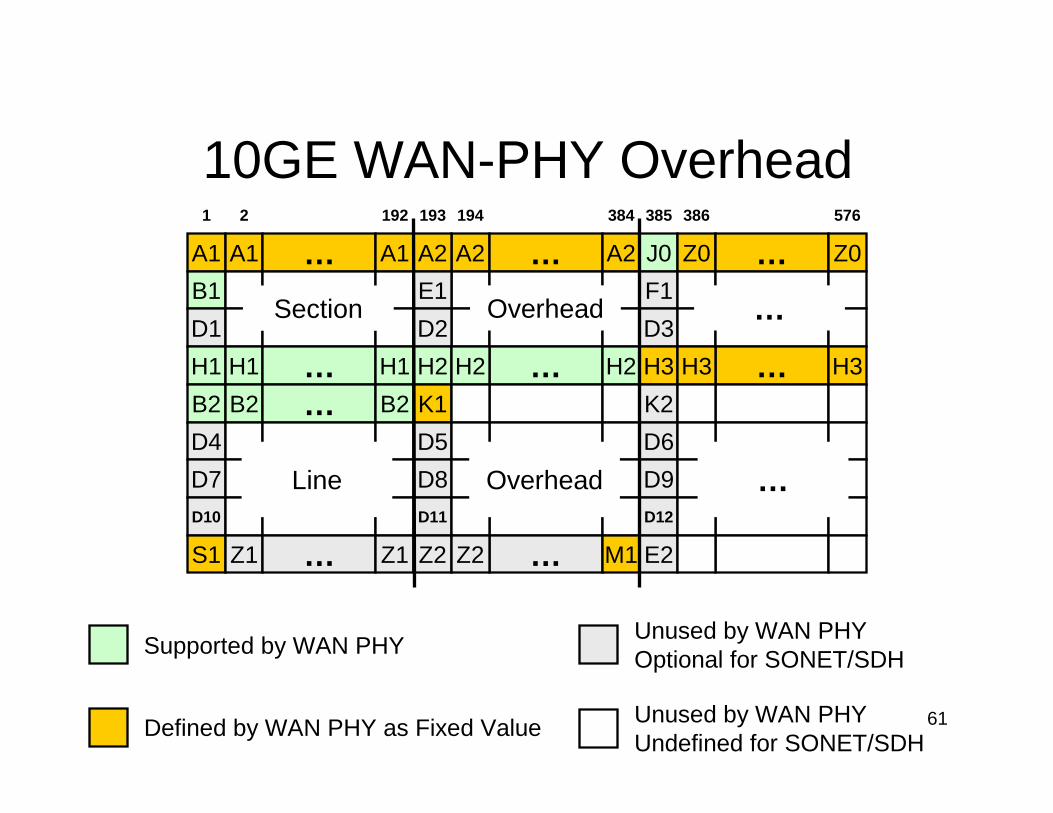
10GE WAN-PHY Overhead
A1
B1
D1
A1 … A1 A2 … A2
Section
A2
E1
D2
J0
F1
D3
Z0 … Z0
Overhead …
H1
B2
D4
D7
D10
S1
H1
B2
Z1
……
…
H1
B2
Z1
H2
K1
D5
D8
D11
Z2
…
…
H2
Z2
H2
M1
H3
K2
D6
D9
D12
E2
…H3 H3
Line Overhead …
1 2 192 193 194 384 385 386 576
Defined by WAN PHY as Fixed Value
Supported by WAN PHYUnused by WAN PHYOptional for SONET/SDH
Unused by WAN PHYUndefined for SONET/SDH