Embed Size (px)
Citation preview
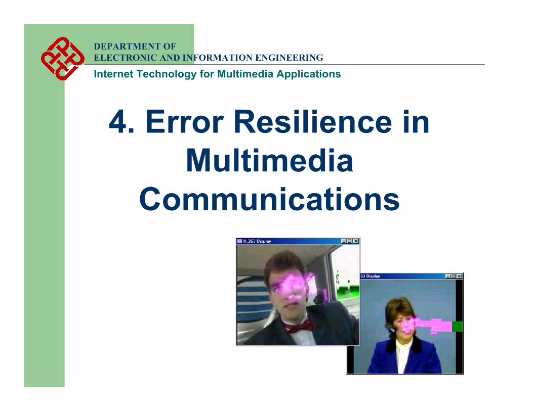
4. Error Resilience in Multimedia
Communications
DEPARTMENT OF ELECTRONIC AND INFORMATION ENGINEERING
Internet Technology for Multimedia Applications

Contents1. Errors in Internet Multimedia Communications
2. Error Propagation in Multimedia Signals
3. Rate Control Mechanism
4. Error Resilient Coding Techniques
5. Error Resilience In Communication Systems
Case study: H.324M
DEPARTMENT OF ELECTRONIC AND INFORMATION ENGINEERING
Internet Technology for Multimedia Applications
DEPARTMENT OF ELECTRONIC AND INFORMATION ENGINEERING
Internet Technology for Multimedia Applications
References 1. F.L. Leannec, F. Toutain and C. Guillemot, “Packet loss resilient
MPEG-4 complaint video coding for the Internet”, Signal Processing: Image Communication, no.15, 1999, pp.35-56.
2. A. Ortega and K. Ramchandran, “Rate-distortion methods for image and video compression”, IEEE Signal Processing Magazine, Nov 1998, pp.23-50.
3. N. Farber and B. Girod, “Extensions of ITU-T Recommendation H.324 for Error-Resilient Video Transmission”, IEEE Communication Magazine, June 1998, pp.120-128.
4. Y. Wang and Q.F. Zhu, “Error control and concealment for video communication: A review”, Proceedings of the IEEE, vol.86, no.5,May 1998, pp.974-997.
DEPARTMENT OF ELECTRONIC AND INFORMATION ENGINEERING
Internet Technology for Multimedia Applications
1. Errors in Internet Multimedia Communications
DEPARTMENT OF ELECTRONIC AND INFORMATION ENGINEERING
Internet Technology for Multimedia Applications
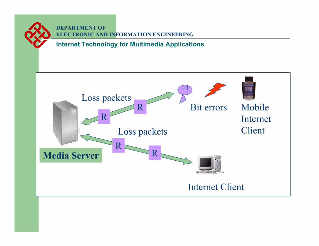
Media Server
Internet Client
RR
Loss packetsR
Loss packetsR Bit errors Mobile
Internet Client
DEPARTMENT OF ELECTRONIC AND INFORMATION ENGINEERING
Internet Technology for Multimedia Applications
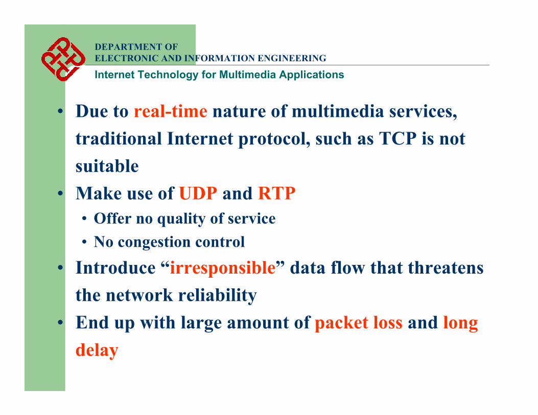
• Due to real-time nature of multimedia services, traditional Internet protocol, such as TCP is not suitable
• Make use of UDP and RTP• Offer no quality of service• No congestion control
• Introduce “irresponsible” data flow that threatens the network reliability
• End up with large amount of packet loss and long delay
DEPARTMENT OF ELECTRONIC AND INFORMATION ENGINEERING
Internet Technology for Multimedia Applications
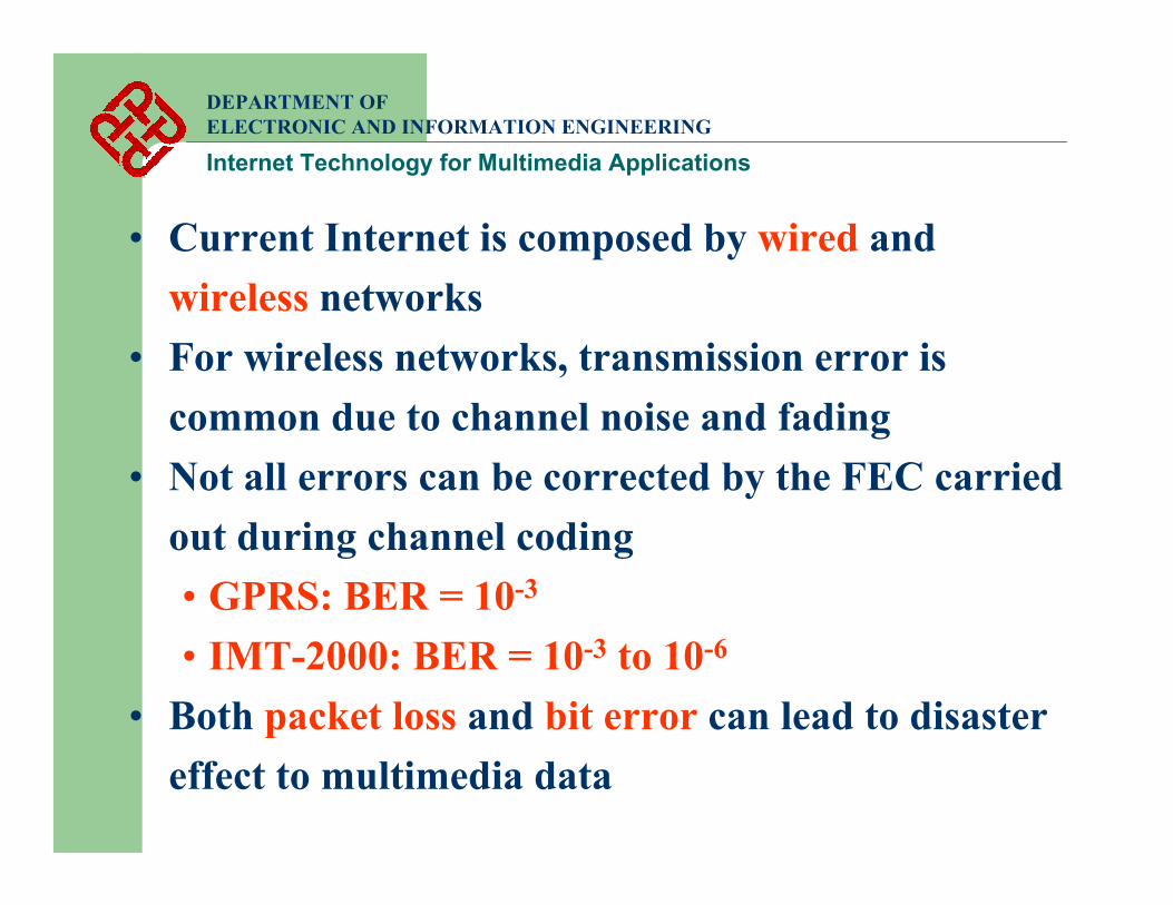
• Current Internet is composed by wired and wireless networks
• For wireless networks, transmission error is common due to channel noise and fading
• Not all errors can be corrected by the FEC carried out during channel coding • GPRS: BER = 10-3
• IMT-2000: BER = 10-3 to 10-6
• Both packet loss and bit error can lead to disaster effect to multimedia data
DEPARTMENT OF ELECTRONIC AND INFORMATION ENGINEERING
Internet Technology for Multimedia Applications
2. Error Propagation in Multimedia Signals

DEPARTMENT OF ELECTRONIC AND INFORMATION ENGINEERING
Internet Technology for Multimedia Applications
• Multimedia signals widely make use of predictiveand variable length coding
• Effect of errors in predictive codes⇒ If any error occurs, it propagates to the media
units that are predicted from it• Effect of errors in variable length codes
⇒ If any error occurs, it may not be detected until several media units later
A. Image coding basics
DEPARTMENT OF ELECTRONIC AND INFORMATION ENGINEERING
Internet Technology for Multimedia Applications
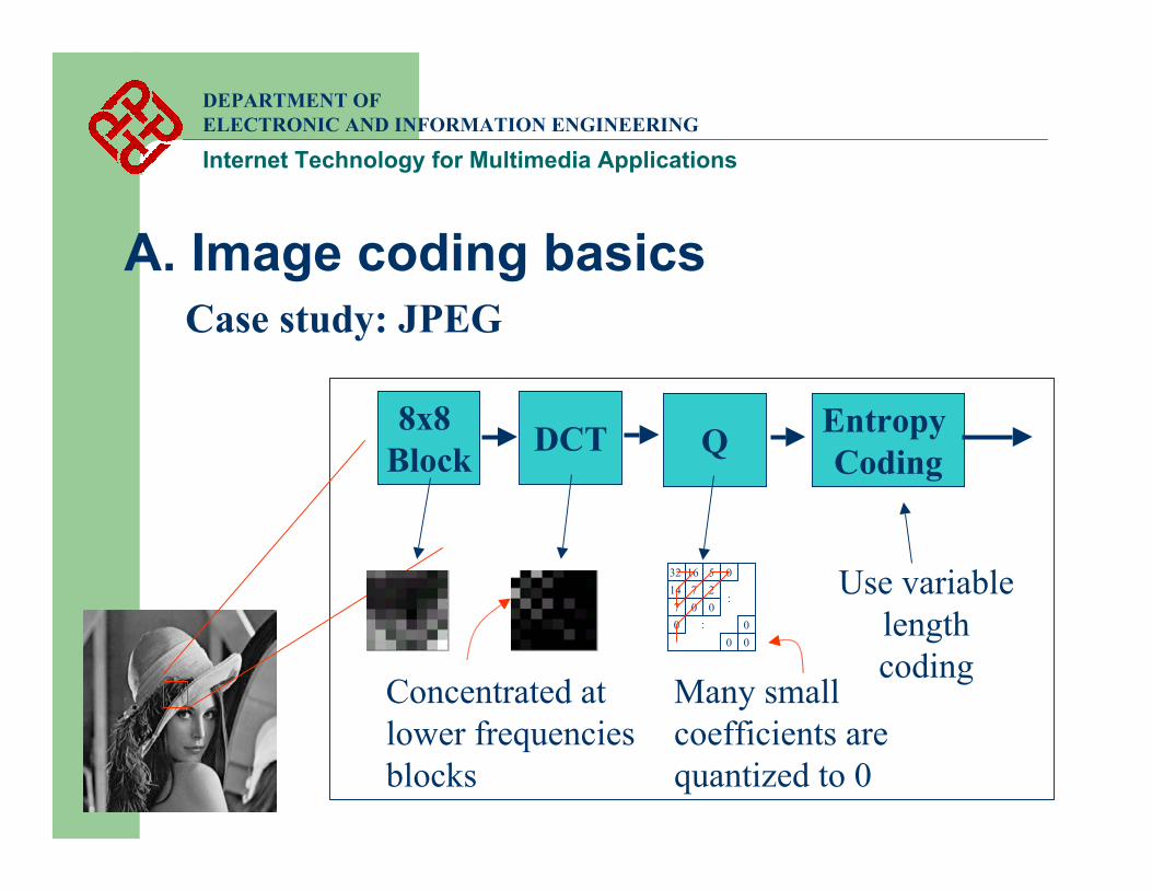
Case study: JPEG
8x8 Block DCT Q Entropy
Coding
Concentrated at lower frequencies blocks
32 16714
5
720
0 0
000
0
:
:Use variable
length coding
Many small coefficients are quantized to 0

Variable Length Coding
• The idea of VLC is to let the most frequently used codes use less bits and less frequently used codes use more bits
Example
Original H.261 TCOEFF Sequence:
0 2 0 0 3 4 ... ... ... 0 0000 110s1 0001 10s2 0000 100s2 0000 0010 11s
4223
VLC:0001100 00000010110 00001100 ... ... ... ... Esc 0000 01
Run Level CodeEOB 10
0 11s0 0100 s
12
VLC TableVLC Table
DEPARTMENT OF ELECTRONIC AND INFORMATION ENGINEERING
Internet Technology for Multimedia Applications
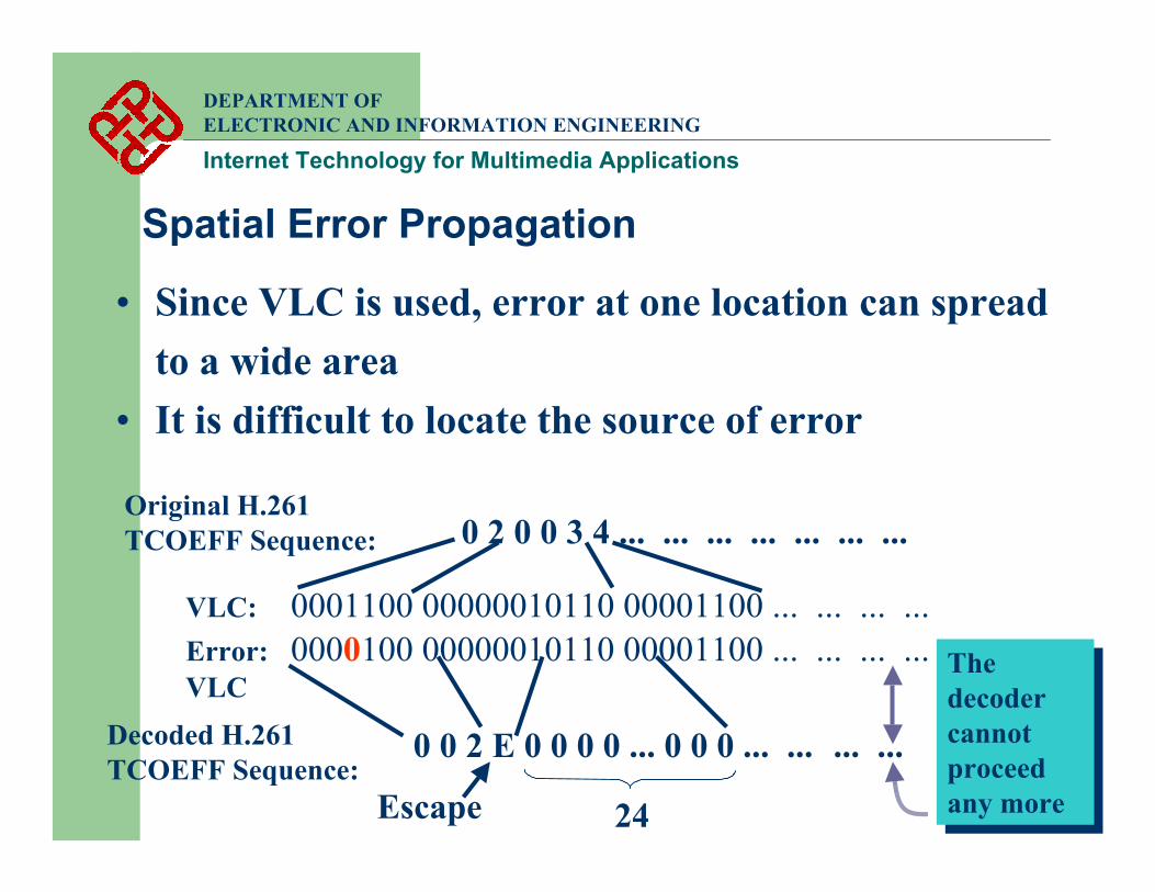
Spatial Error Propagation
• Since VLC is used, error at one location can spread to a wide area
• It is difficult to locate the source of error
Original H.261 TCOEFF Sequence:
VLC: 0001100 00000010110 00001100 ... ... ... ...Error: 0000100 00000010110 00001100 ... ... ... ...VLC
Decoded H.261 TCOEFF Sequence:
0 0 2 E 0 0 0 0 ... 0 0 0 ... ... ... ...
0 2 0 0 3 4 ... ... ... ... ... ... ...
24
The decoder cannot proceed any more
The decoder cannot proceed any moreEscape
DEPARTMENT OF ELECTRONIC AND INFORMATION ENGINEERING
Internet Technology for Multimedia Applications
DEPARTMENT OF ELECTRONIC AND INFORMATION ENGINEERING
Internet Technology for Multimedia Applications
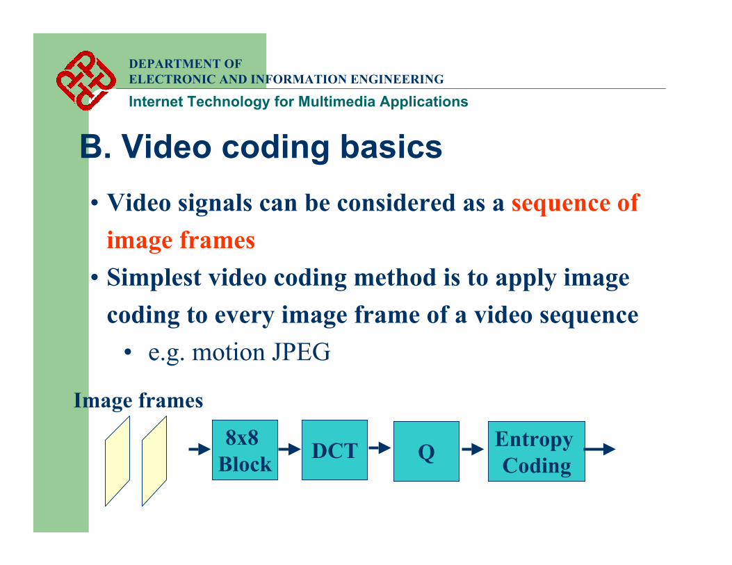
B. Video coding basics• Video signals can be considered as a sequence of
image frames• Simplest video coding method is to apply image
coding to every image frame of a video sequence• e.g. motion JPEG
8x8 Block DCT Q Entropy
Coding
Image frames
DEPARTMENT OF ELECTRONIC AND INFORMATION ENGINEERING
Internet Technology for Multimedia Applications
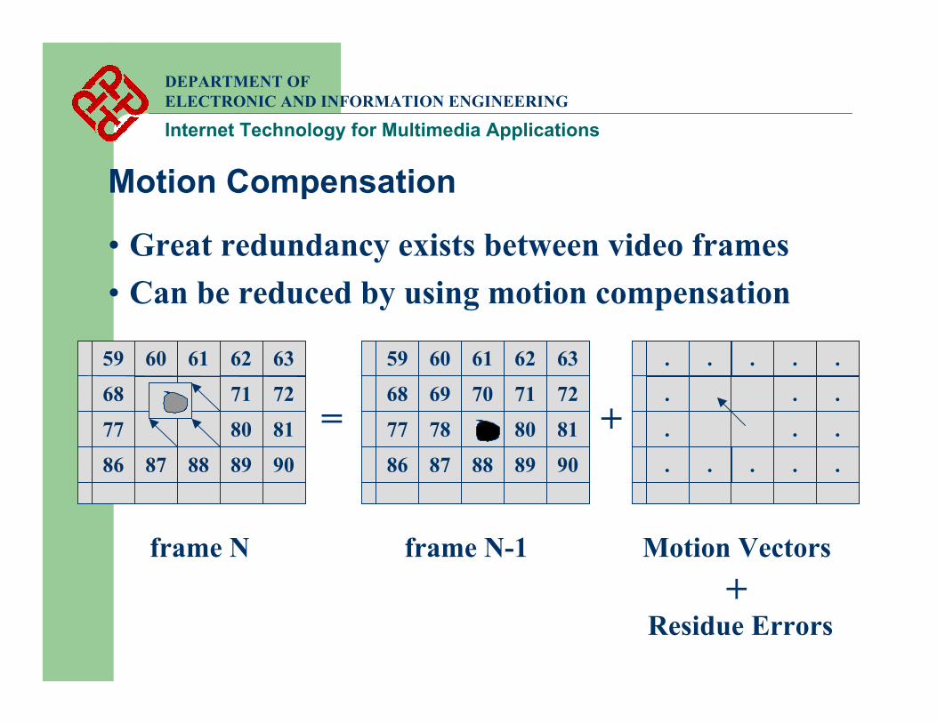
Motion Compensation
• Great redundancy exists between video frames• Can be reduced by using motion compensation
59 626160 63
68 71 72
77 80 81
86 898887 90
frame N-1frame N
= +
. ... .
. . .
. . .
. ... .
Motion Vectors
59 626160 63
68 717069 72
77 8078 81
86 898887 90
+Residue Errors
DCT Q Entropy Coding
Q-1
DCT-1
DEPARTMENT OF ELECTRONIC AND INFORMATION ENGINEERING
Internet Technology for Multimedia Applications
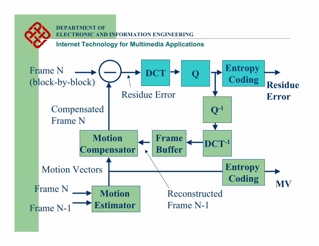
Motion Estimator
Frame N
Frame N-1
Motion Compensator
Motion Vectors
Frame N(block-by-block)
ReconstructedFrame N-1
FrameBuffer
CompensatedFrame N
Residue Error
MV
Residue Error
Entropy Coding
DEPARTMENT OF ELECTRONIC AND INFORMATION ENGINEERING
Internet Technology for Multimedia Applications
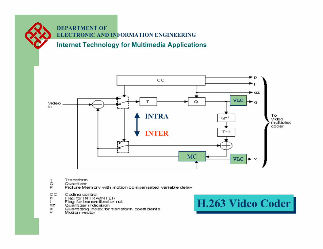
H.263 Video CoderH.263 Video Coder
INTRA
INTER
VLC
VLCMC
INTRA and INTER Frames
DEPARTMENT OF ELECTRONIC AND INFORMATION ENGINEERING
Internet Technology for Multimedia Applications
• For H.263 or MPEG codec, video frames can be encoded in one of the two modes
• INTRA and INTER• INTRA (I) mode – simply an image coder (JPEG)
• No reference is made to other frames• Lower compression efficiency
• INTER (P) mode, motion compensation is applied• Video frame is predicted from previous frames• Higher compression efficiency but introduce temporal
error propagation
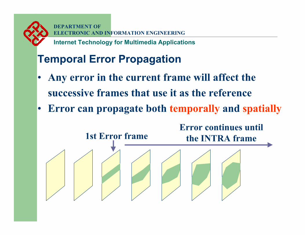
Temporal Error Propagation• Any error in the current frame will affect the
successive frames that use it as the reference• Error can propagate both temporally and spatially
1st Error frameError continues until
the INTRA frame
DEPARTMENT OF ELECTRONIC AND INFORMATION ENGINEERING
Internet Technology for Multimedia Applications
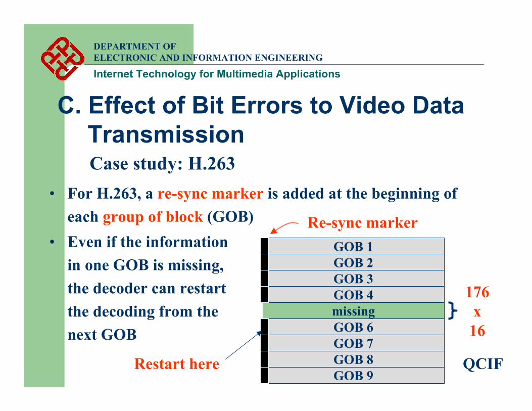
C. Effect of Bit Errors to Video Data Transmission
DEPARTMENT OF ELECTRONIC AND INFORMATION ENGINEERING
Internet Technology for Multimedia Applications
Case study: H.263
QCIF
176 x 16
GOB 4missingGOB 6GOB 7GOB 8GOB 9
GOB 1GOB 2GOB 3
Re-sync marker
• For H.263, a re-sync marker is added at the beginning of each group of block (GOB)
• Even if the information in one GOB is missing, the decoder can restart the decoding from the next GOB
Restart here
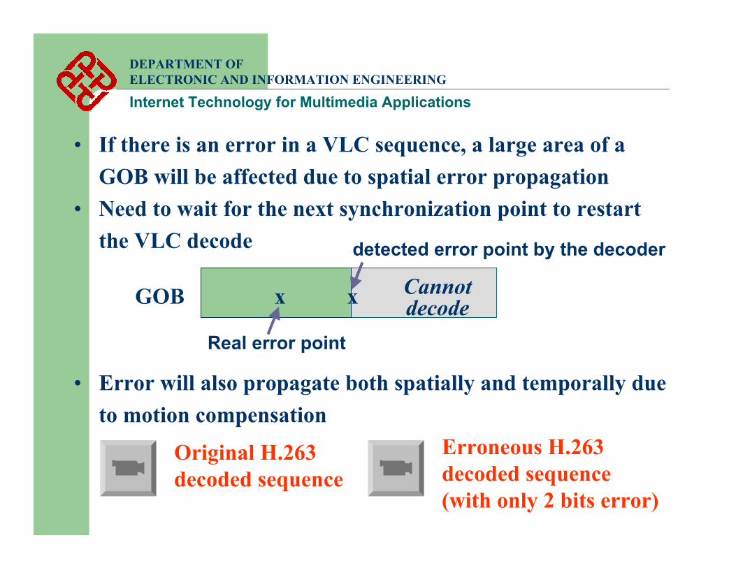
• If there is an error in a VLC sequence, a large area of a GOB will be affected due to spatial error propagation
• Need to wait for the next synchronization point to restart the VLC decode
xGOB
Real error point
detected error point by the decoder
x Cannot decode
DEPARTMENT OF ELECTRONIC AND INFORMATION ENGINEERING
Internet Technology for Multimedia Applications
Original H.263 decoded sequence
Erroneous H.263 decoded sequence(with only 2 bits error)
• Error will also propagate both spatially and temporally due to motion compensation
DEPARTMENT OF ELECTRONIC AND INFORMATION ENGINEERING
Internet Technology for Multimedia Applications
D. Effect of Packet Loss to Video Streaming on Internet
• General Internet errors:• Packets received in wrong order• Packet delay • Packet loss
• Use of RTP and RTCP resolves some of the problems, but not all
Case study: H.263
DEPARTMENT OF ELECTRONIC AND INFORMATION ENGINEERING
Internet Technology for Multimedia Applications
Packets Received in Wrong Order
• Due to multiple path routing, packets may go thru different routes to the destination
• Late packets may go faster than the earlier ones• Each RTP packet has a sequence number• The receiving unit can rearrange the order of the
received RTP packets for display
DEPARTMENT OF ELECTRONIC AND INFORMATION ENGINEERING
Internet Technology for Multimedia Applications
Packets Delay• Data packets may experience delay due to the
routers in the path• Many multimedia signals, e.g. video, audio, speech,
etc. are time dependent• Need to be received at a specified time• Problem can be resolved by having an initial
buffering stage• If delay time is longer than the maximum playback
time of the data in the buffer, jittering is resulted
DEPARTMENT OF ELECTRONIC AND INFORMATION ENGINEERING
Internet Technology for Multimedia Applications
Packets Loss
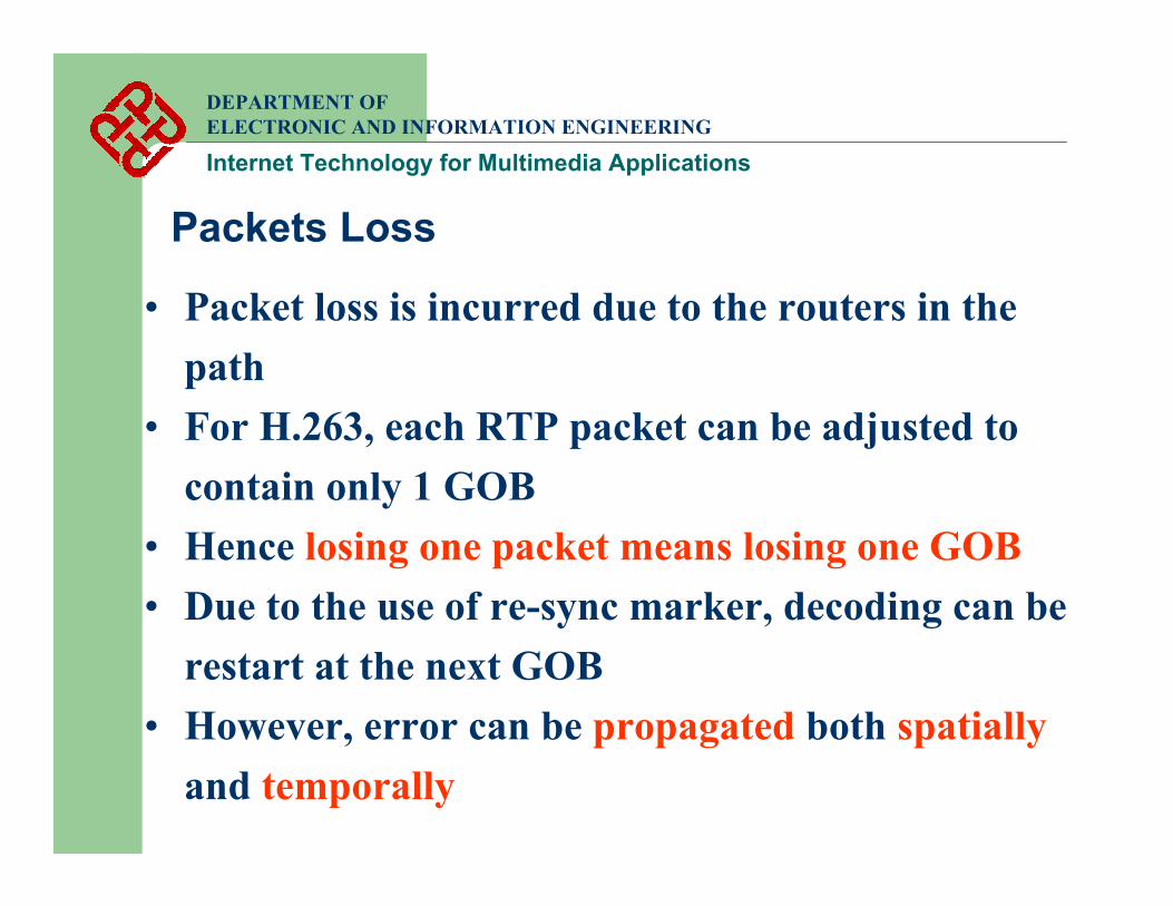
• Packet loss is incurred due to the routers in the path
• For H.263, each RTP packet can be adjusted to contain only 1 GOB
• Hence losing one packet means losing one GOB• Due to the use of re-sync marker, decoding can be
restart at the next GOB• However, error can be propagated both spatially
and temporally
DEPARTMENT OF ELECTRONIC AND INFORMATION ENGINEERING
Internet Technology for Multimedia Applications
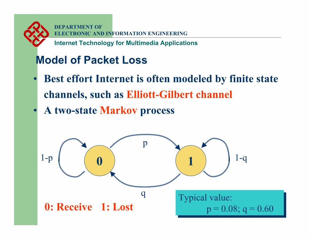
Model of Packet Loss• Best effort Internet is often modeled by finite state
channels, such as Elliott-Gilbert channel• A two-state Markov process
0 1p
q
1-q1-p
0: Receive 1: LostTypical value:
p = 0.08; q = 0.60Typical value:
p = 0.08; q = 0.60
DEPARTMENT OF ELECTRONIC AND INFORMATION ENGINEERING
Internet Technology for Multimedia Applications
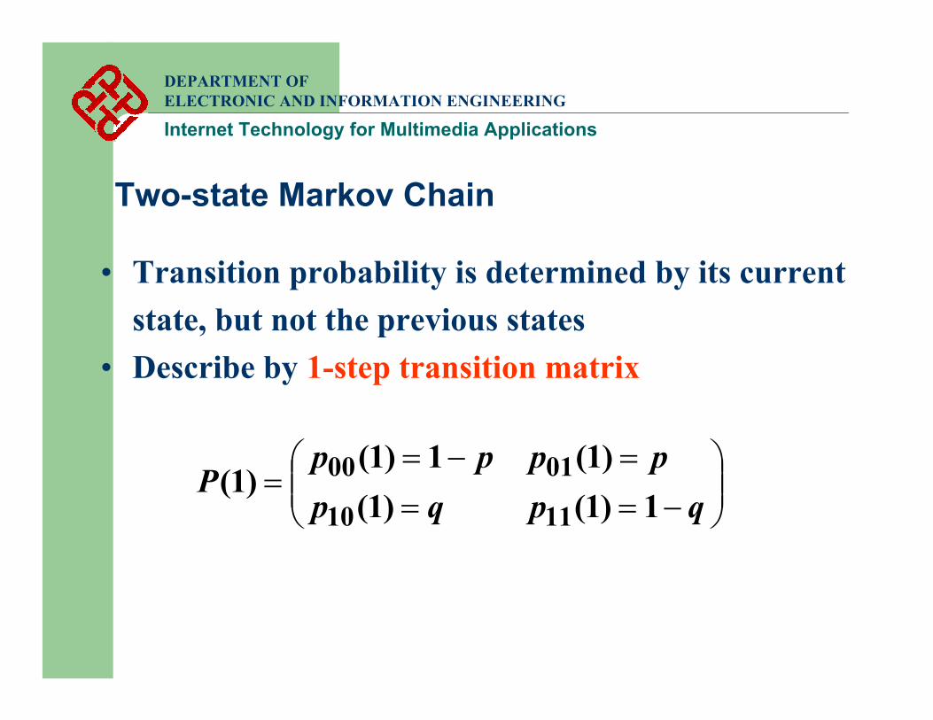
Two-state Markov Chain
• Transition probability is determined by its current state, but not the previous states
• Describe by 1-step transition matrix
−==
=−==
qpqppppp
P1)1()1(
)1(1)1()1(
1110
0100
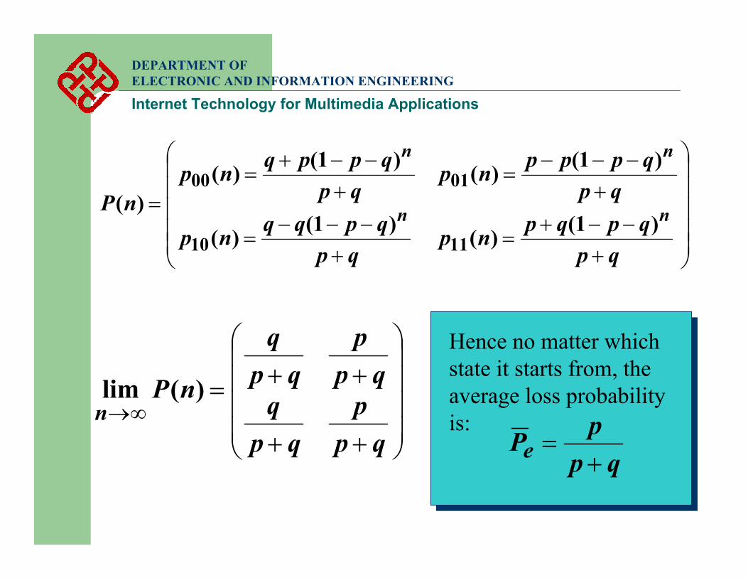
+−−+
=+
−−−=
+−−−
=+
−−+=
=
qpqpqpnp
qpqpqqnp
qpqpppnp
qpqppqnp
nP nn
nn
)1()()1()(
)1()()1()()(
1110
0100
DEPARTMENT OF ELECTRONIC AND INFORMATION ENGINEERING
Internet Technology for Multimedia Applications
++
++=∞→
qpp
qpq
qpp
qpq
nPn
)(lim
Hence no matter which state it starts from, the average loss probability is:
qppPe +
=
DEPARTMENT OF ELECTRONIC AND INFORMATION ENGINEERING
Internet Technology for Multimedia Applications
E. Summary
• To avoid the network being congested by the irresponsible RTP/UDP traffic, rate controlmechanism should be upheld
• While bit error or packet loss is unavoidable, error resilient techniques should be applied to communication system
DEPARTMENT OF ELECTRONIC AND INFORMATION ENGINEERING
Internet Technology for Multimedia Applications
3. Rate Control Mechanism
DEPARTMENT OF ELECTRONIC AND INFORMATION ENGINEERING
Internet Technology for Multimedia Applications
A. Introduction• To achieve rate control, the following
information should be obtained• The appropriate rate – determine by network
performance• The approaches to achieve such rate – mostly
determine by the coding system• The effect of using such rate – usually indicate by the
distortion introduced
DEPARTMENT OF ELECTRONIC AND INFORMATION ENGINEERING
Internet Technology for Multimedia Applications
Determine the rate• The transmission data rate should adapt to the
network condition• Incipient congestion should be detected and react
by lowering the rate• Quantities that are usually monitored include
• Packet Loss• Round-trip time (RTT) delay
• Require feedback from the client• Made easy by using RTP / RTCP
DEPARTMENT OF ELECTRONIC AND INFORMATION ENGINEERING
Internet Technology for Multimedia Applications
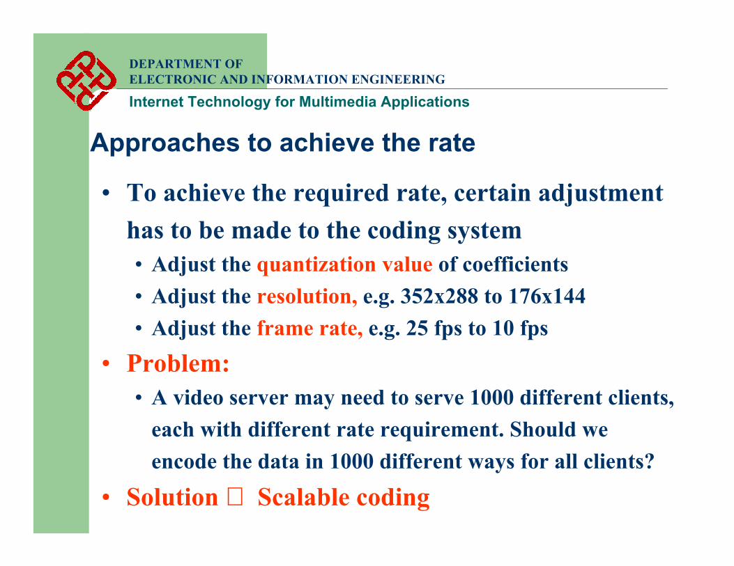
Approaches to achieve the rate
• To achieve the required rate, certain adjustment has to be made to the coding system• Adjust the quantization value of coefficients• Adjust the resolution, e.g. 352x288 to 176x144• Adjust the frame rate, e.g. 25 fps to 10 fps
• Problem:• A video server may need to serve 1000 different clients,
each with different rate requirement. Should we encode the data in 1000 different ways for all clients?
• Solution ⇒ Scalable coding
DEPARTMENT OF ELECTRONIC AND INFORMATION ENGINEERING
Internet Technology for Multimedia Applications
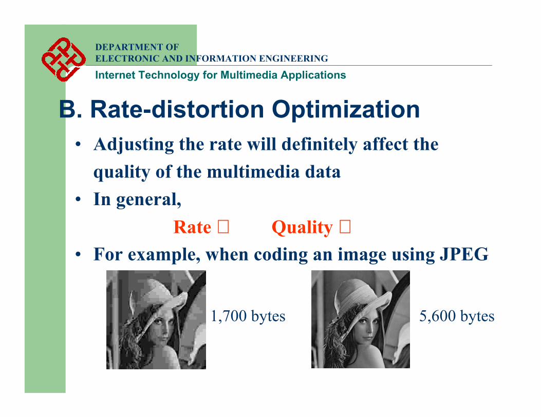
B. Rate-distortion Optimization• Adjusting the rate will definitely affect the
quality of the multimedia data• In general,
Rate ⇑ Quality ⇑• For example, when coding an image using JPEG
1,700 bytes 5,600 bytes
DEPARTMENT OF ELECTRONIC AND INFORMATION ENGINEERING
Internet Technology for Multimedia Applications
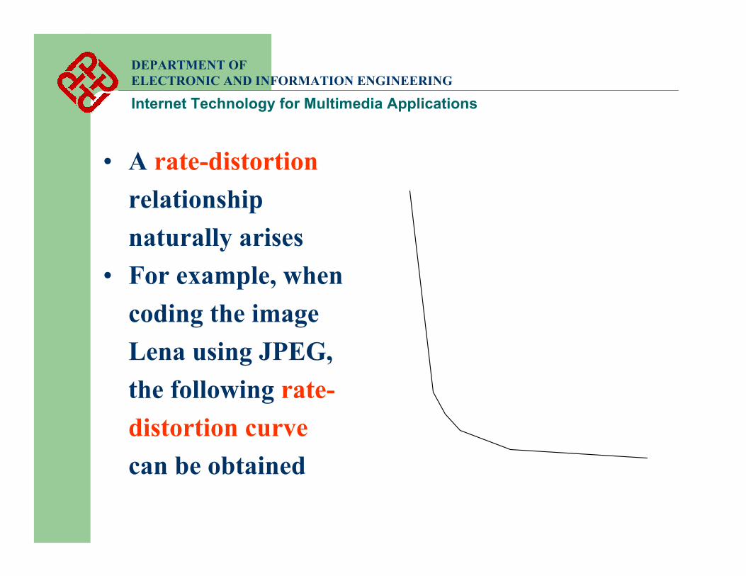
• A rate-distortionrelationship naturally arises
• For example, when coding the image Lena using JPEG, the following rate-distortion curvecan be obtained
DEPARTMENT OF ELECTRONIC AND INFORMATION ENGINEERING
Internet Technology for Multimedia Applications
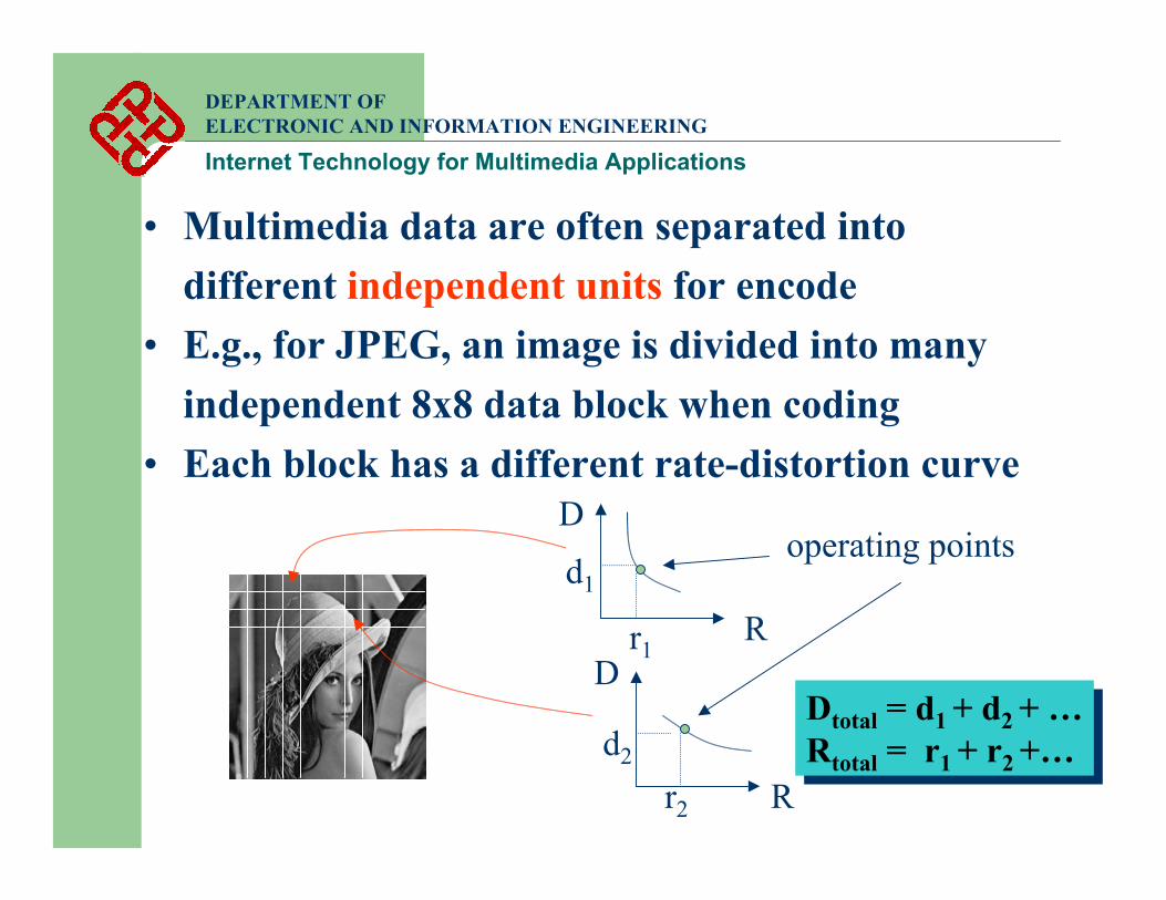
• Multimedia data are often separated into different independent units for encode
• E.g., for JPEG, an image is divided into many independent 8x8 data block when coding
• Each block has a different rate-distortion curve
R
R
D
D
operating pointsd1
r1
r2
d2Dtotal = d1 + d2 + …Rtotal = r1 + r2 +…Dtotal = d1 + d2 + …Rtotal = r1 + r2 +…
DEPARTMENT OF ELECTRONIC AND INFORMATION ENGINEERING
Internet Technology for Multimedia Applications
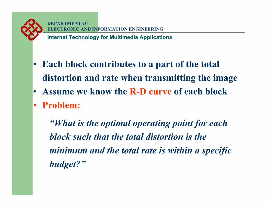
• Each block contributes to a part of the total distortion and rate when transmitting the image
• Assume we know the R-D curve of each block• Problem:
“What is the optimal operating point for each block such that the total distortion is the minimum and the total rate is within a specific budget?”
DEPARTMENT OF ELECTRONIC AND INFORMATION ENGINEERING
Internet Technology for Multimedia Applications
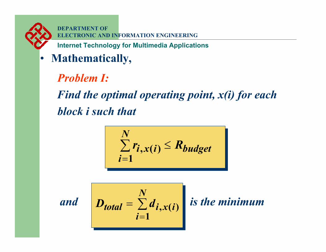
Problem I:Find the optimal operating point, x(i) for each block i such that
• Mathematically,
∑=
≤N
ibudgetixi Rr
1)(,
and is the minimum∑=
=N
iixitotal dD
1)(,
DEPARTMENT OF ELECTRONIC AND INFORMATION ENGINEERING
Internet Technology for Multimedia Applications
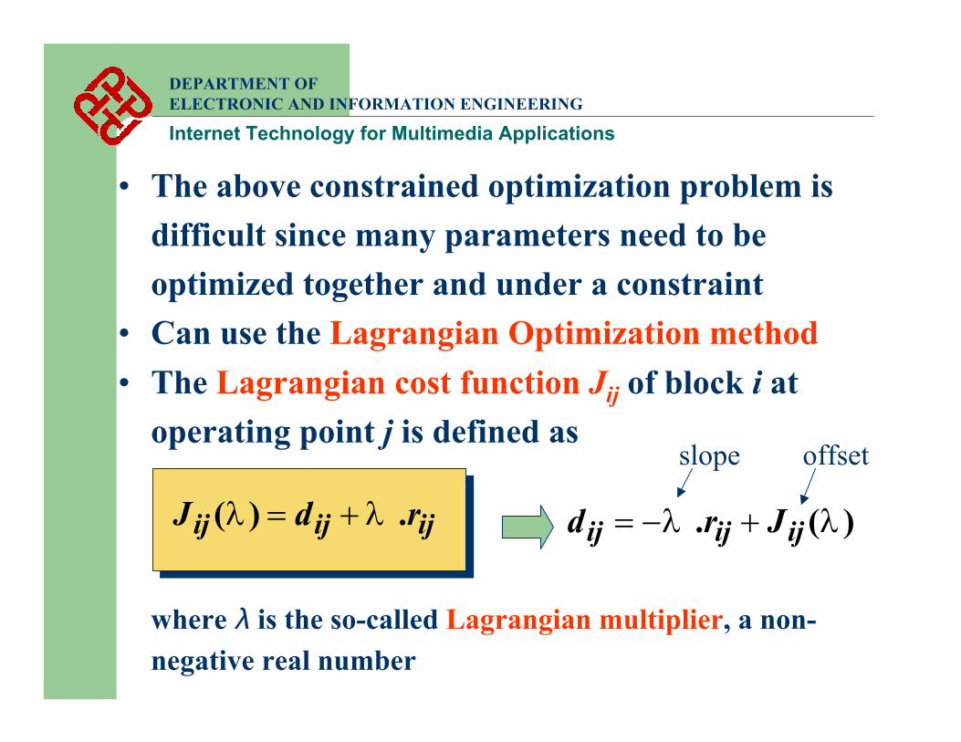
• The above constrained optimization problem is difficult since many parameters need to be optimized together and under a constraint
• Can use the Lagrangian Optimization method• The Lagrangian cost function Jij of block i at
operating point j is defined as
ijijij rdJ .)( λλ +=
where λ is the so-called Lagrangian multiplier, a non-negative real number
)(. λλ ijijij Jrd +−=
slope offset

DEPARTMENT OF ELECTRONIC AND INFORMATION ENGINEERING
Internet Technology for Multimedia Applications
R
DBlock idi1, ri1
di2, ri2
di3, ri3
di4, ri4
Slope = -λ
Ji2
)(. 222 λλ iii Jrd +−=
Ji2 < Ji3 < Ji1 < Ji4 Ji2 < Ji3 < Ji1 < Ji4
The d-r point where the line of absolute slope λfirst hits at when moving from left to right gives the minimum J
DEPARTMENT OF ELECTRONIC AND INFORMATION ENGINEERING
Internet Technology for Multimedia Applications
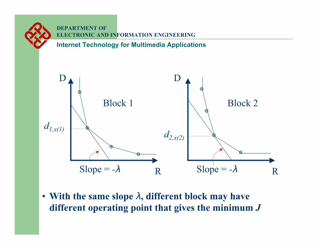
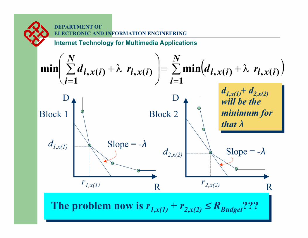
RSlope = -λRSlope = -λ
D D
Block 1 Block 2
d1,x(1) d2,x(2)
• With the same slope λ, different block may have different operating point that gives the minimum J
DEPARTMENT OF ELECTRONIC AND INFORMATION ENGINEERING
Internet Technology for Multimedia Applications
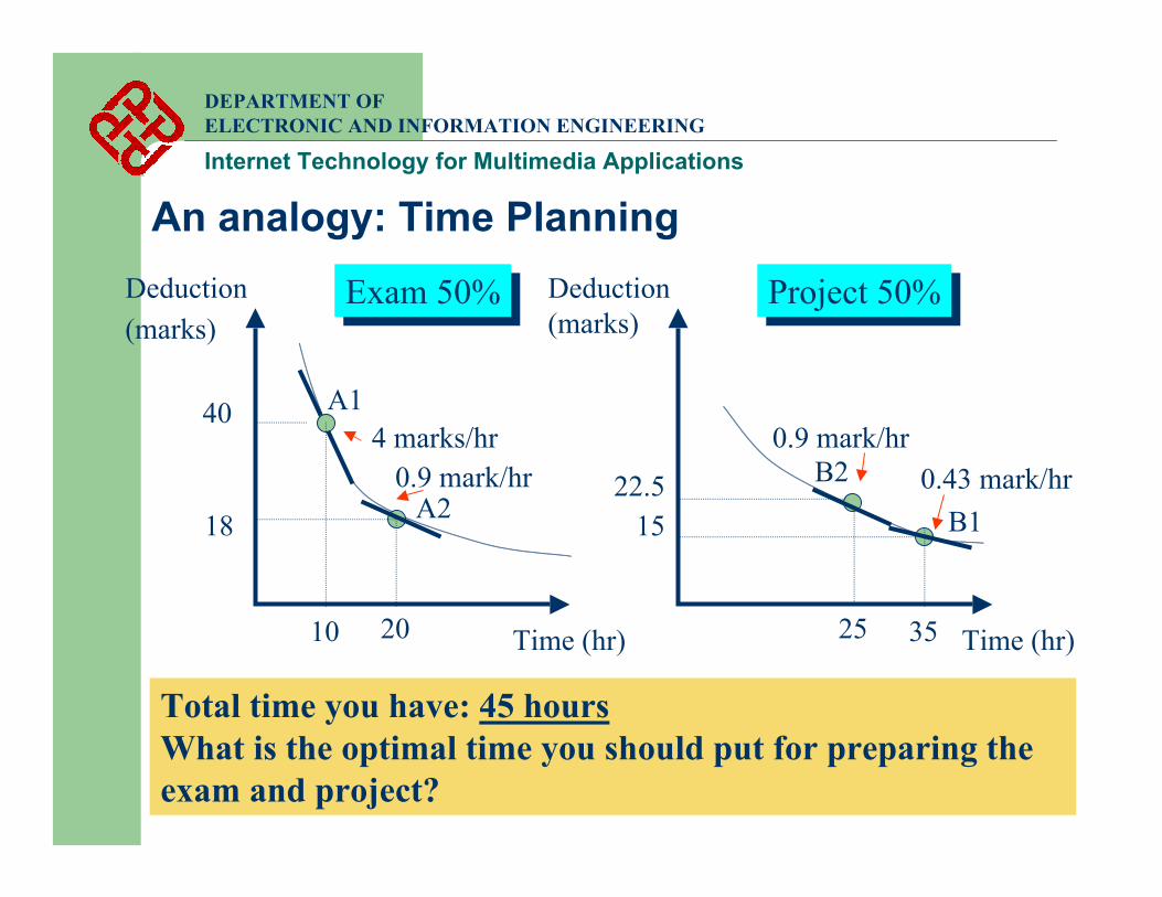
An analogy: Time Planning
Time (hr)Time (hr)
Deduction (marks)
Exam 50%Exam 50% Project 50%Project 50%Deduction (marks)
Total time you have: 45 hoursWhat is the optimal time you should put for preparing the exam and project?
10
404 marks/hr
A1
35
150.43 mark/hr
B1
20
18
0.9 mark/hrA2
25
0.9 mark/hr
22.5 B2
DEPARTMENT OF ELECTRONIC AND INFORMATION ENGINEERING
Internet Technology for Multimedia Applications
• The optimal time is obtained by looking for the operating points that have the same slope, say λ, in both curves
⇒ e.g. 0.9 mark / hour
• The total mark deducted will be the minimum at that point⇒ 40.5 marks as compared to 55 marks at (A1, B1)
• Here we restrict the total time spent is at exactly 45 hours. Only one λ will satisfy the condition
• If we relax the requirement that the total time spent is within 45 hours, more λ will satisfy the condition
• We may need to test each λ one-by-one to see which one will give the lower total mark loss
DEPARTMENT OF ELECTRONIC AND INFORMATION ENGINEERING
Internet Technology for Multimedia Applications
• As apply to problem I,
Exam and project ⇒ Block 1 and 2Mark deducted in exam ⇒ DistortionTime ⇒ RateLine with constant slope ⇒ Lagrangian cost functionTotal time spent ⇒ Rate budgetTotal mark deducted ⇒ Total distortion
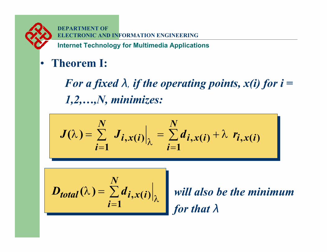
• Theorem I:
For a fixed λ, if the operating points, x(i) for i = 1,2,…,N, minimizes:
)(,1
)(,)(,1
)( ixiN
iixiixi
N
irdJJ λλ
λ+== ∑∑
==
DEPARTMENT OF ELECTRONIC AND INFORMATION ENGINEERING
Internet Technology for Multimedia Applications
will also be the minimum for that λ
∑=
=N
iixitotal dD
1)(,)(λ
λ
DEPARTMENT OF ELECTRONIC AND INFORMATION ENGINEERING
Internet Technology for Multimedia Applications
R
Slope = -λ
R
Slope = -λ
D D
Block 1 Block 2
d1,x(1) d2,x(2)
d1,x(1)+ d2,x(2)will be the minimum for that λ
d1,x(1)+ d2,x(2)will be the minimum for that λ
( )∑∑==
+=
+
N
iixiixiixi
N
iixi rdrd
1)(,)(,)(,
1)(, minmin λλ
r1,x(1) r2,x(2)
The problem now is r1,x(1) + r2,x(2) ≤ RBudget???
DEPARTMENT OF ELECTRONIC AND INFORMATION ENGINEERING
Internet Technology for Multimedia Applications
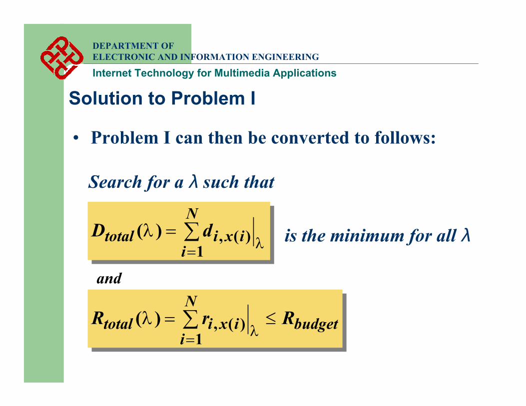
Search for a λ such that
is the minimum for all λ
• Problem I can then be converted to follows:
∑=
=N
iixitotal dD
1)(,)(λ
λ
budgetN
iixitotal RrR ≤= ∑
=1)(,)(λ
λ
and
Solution to Problem I
DEPARTMENT OF ELECTRONIC AND INFORMATION ENGINEERING
Internet Technology for Multimedia Applications
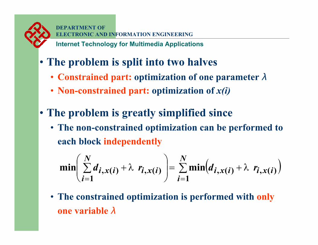
• The problem is split into two halves• Constrained part: optimization of one parameter λ• Non-constrained part: optimization of x(i)
• The problem is greatly simplified since• The non-constrained optimization can be performed to
each block independently
• The constrained optimization is performed with only one variable λ
( )∑∑==
+=
+
N
iixiixiixi
N
iixi rdrd
1)(,)(,)(,
1)(, minmin λλ

DEPARTMENT OF ELECTRONIC AND INFORMATION ENGINEERING
Internet Technology for Multimedia Applications
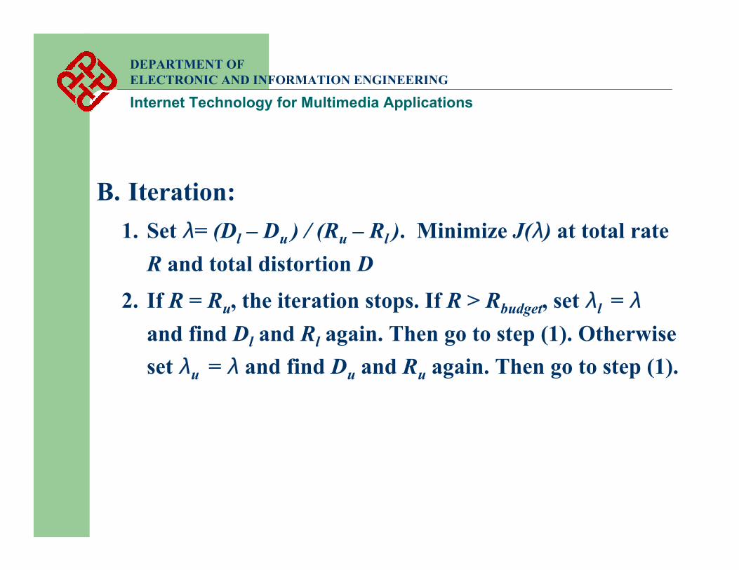
• The searching of best λ can be achieved by using the bisection search algorithm
A. Initialization:1. Set λl = 0. Minimize J(λl ) at total rate Rl and total
distortion Dl
2. Set λu = ∞. Minimize J(λu ) at total rate Ru and total distortion Du
3. Verify that Rl ≤ Rbudget ≤ Ru
4. If Rl = Ru = Rbudget, stop. The current operating point is the solution.
DEPARTMENT OF ELECTRONIC AND INFORMATION ENGINEERING
Internet Technology for Multimedia Applications
B. Iteration:1. Set λ= (Dl – Du ) / (Ru – Rl ). Minimize J(λ) at total rate
R and total distortion D2. If R = Ru, the iteration stops. If R > Rbudget, set λl = λ
and find Dl and Rl again. Then go to step (1). Otherwise set λu = λ and find Du and Ru again. Then go to step (1).
DEPARTMENT OF ELECTRONIC AND INFORMATION ENGINEERING
Internet Technology for Multimedia Applications
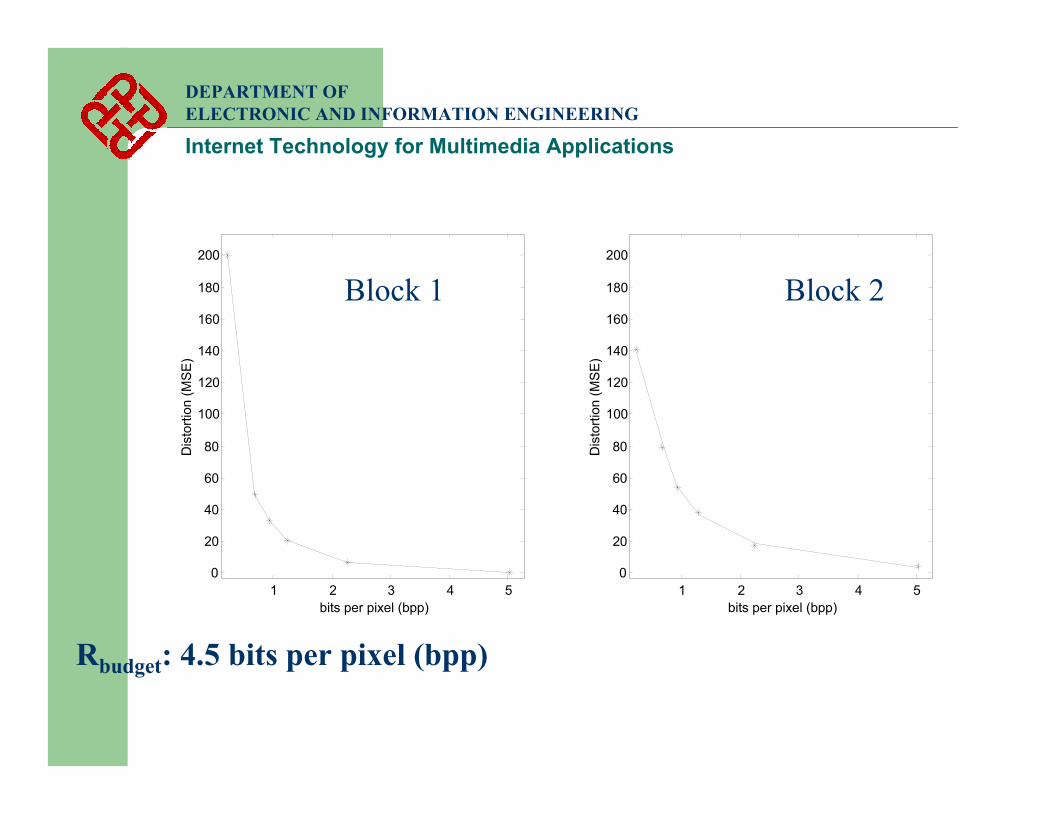
1 2 3 4 50
20
40
60
80
100
120
140
160
180
200
bits per pixel (bpp)D
isto
rtion
(MSE
)
Rbudget: 4.5 bits per pixel (bpp)
1 2 3 4 50
20
40
60
80
100
120
140
160
180
200
bits per pixel (bpp)
Dis
torti
on (M
SE)
Block 1 Block 2
DEPARTMENT OF ELECTRONIC AND INFORMATION ENGINEERING
Internet Technology for Multimedia Applications
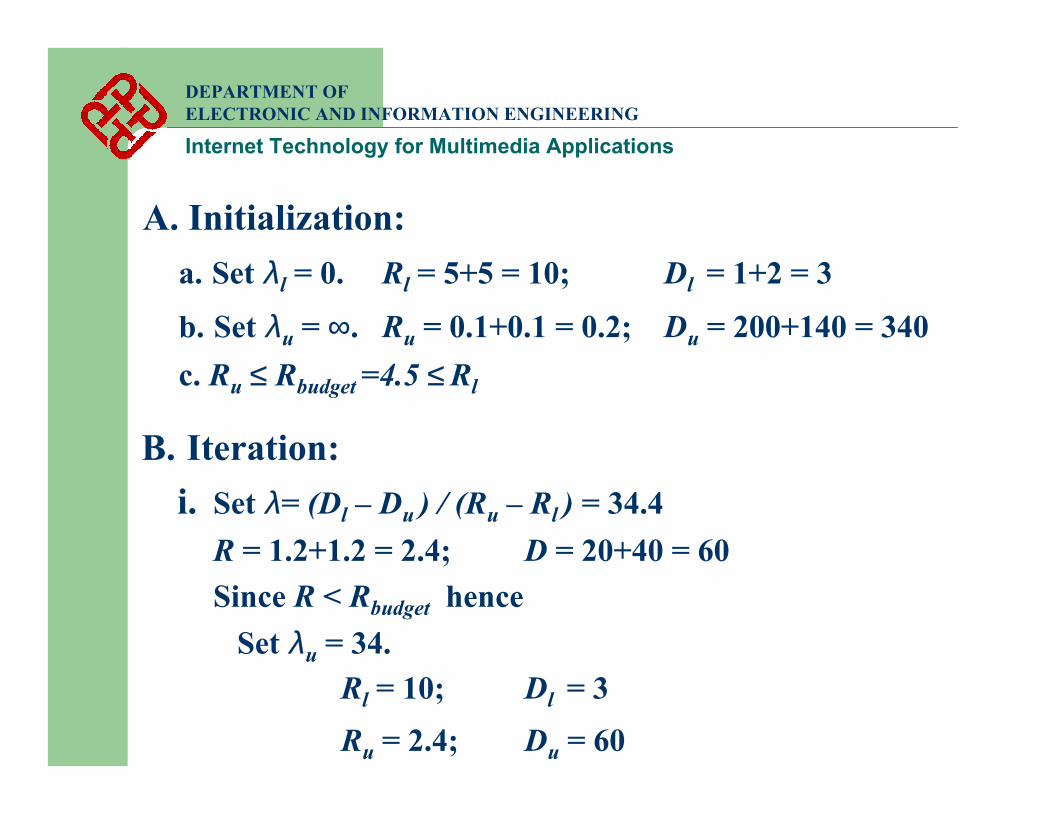
A. Initialization:a. Set λl = 0. Rl = 5+5 = 10; Dl = 1+2 = 3
b. Set λu = ∞. Ru = 0.1+0.1 = 0.2; Du = 200+140 = 340c. Ru ≤ Rbudget =4.5 ≤ Rl
B. Iteration:i. Set λ= (Dl – Du ) / (Ru – Rl ) = 34.4
R = 1.2+1.2 = 2.4; D = 20+40 = 60Since R < Rbudget hence
Set λu = 34.Rl = 10; Dl = 3Ru = 2.4; Du = 60

DEPARTMENT OF ELECTRONIC AND INFORMATION ENGINEERING
Internet Technology for Multimedia Applications
ii. Set λ= (Dl – Du ) / (Ru – Rl ) = 7.5. R = 2.2+2.2 = 4.4; D = 10+20 = 30Since R < Rbudget hence
Set λu = 7.5.Rl = 10; Dl = 3Ru = 4.4; Du = 30
iii. Set λ= (Dl – Du ) / (Ru – Rl ) = 4.8. R = 2.2+2.2 = 4.4; D = 10+20 = 30Since R = Ru , the iteration stops
Final solution: Block 1 – (2.2, 10)Block 2 – (2.2, 20)
Final solution: Block 1 – (2.2, 10)Block 2 – (2.2, 20)


![Multimedia Research [Internet TV ]](https://img.pdfslide.us/doc/110x75/577d39951a28ab3a6b9a1d85/multimedia-research-internet-tv-.jpg)