Embed Size (px)
Citation preview
1© Luciano Bononi 2018 Internet of Things
Luciano Bononi, Marco di Felice([email protected])
Alma Mater Studiorum – University of BolognaDepartment of Computer Science and Engineering
Internet of Things(short introduction to Wireless)
2© Luciano Bononi 2018 Internet of Things
Background on wireless PHY layer
3© Luciano Bononi 2018 Internet of Things
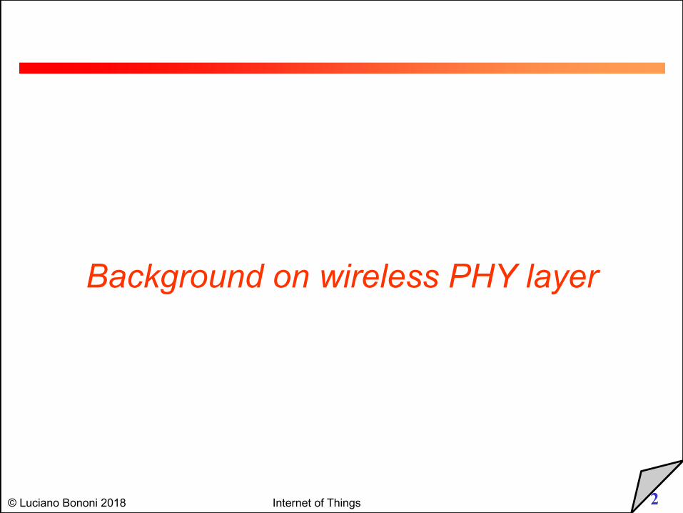
RF Properties
§ Understanding Radio Frequency
• Generation, coverage and propagation issues
• Fundamental for wireless planning and management
• http://faraday.physics.utoronto.ca/PVB/Harrison/Flash/EM/EMWave/EMWave.html
• http://wwwhome.ewi.utwente.nl/~ptdeboer/ham/xnecview/dipole_anim.html
§ Radio Frequency Signals• Electromagnetic energy generated by high frequency alternate current
(AC) in antennas
• Antenna: converts the wired current to RF and viceversal
V
i
RFPropagation
medium?
RF energy(amplitude)
Voltage (electric energy amplitude)
4© Luciano Bononi 2018 Internet of Things
RF Properties
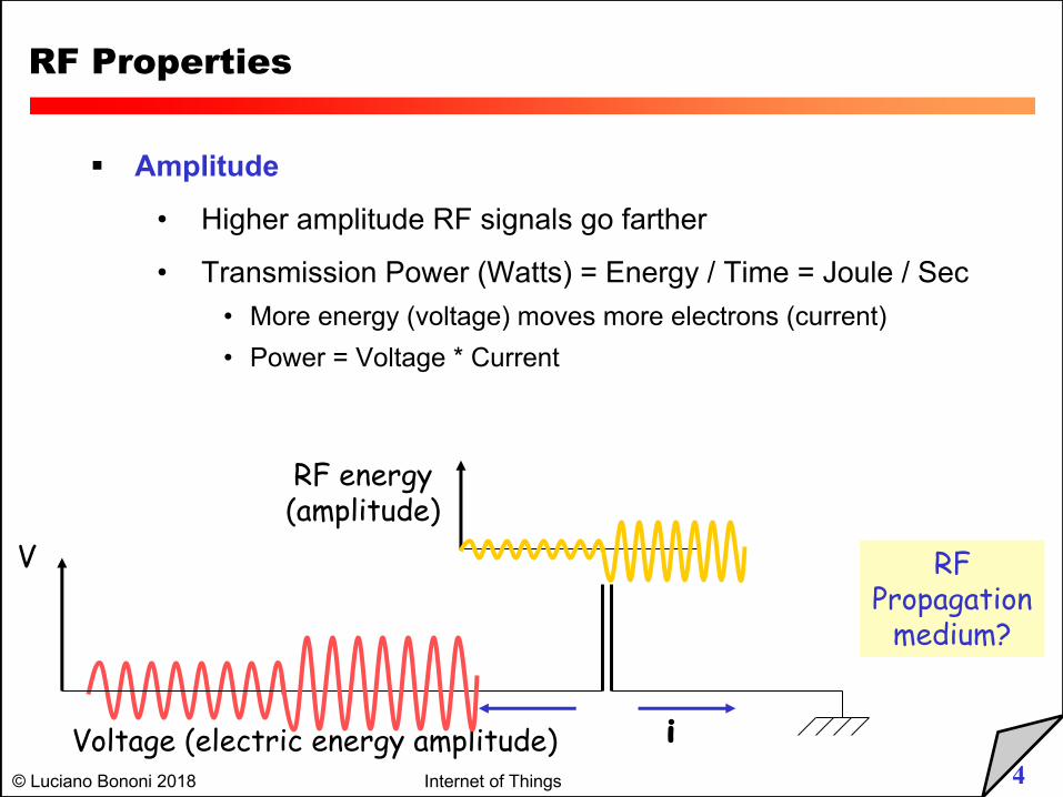
§ Amplitude
• Higher amplitude RF signals go farther
• Transmission Power (Watts) = Energy / Time = Joule / Sec• More energy (voltage) moves more electrons (current)• Power = Voltage * Current
V
i
RFPropagation
medium?
RF energy(amplitude)
Voltage (electric energy amplitude)
5© Luciano Bononi 2018 Internet of Things
RF Properties
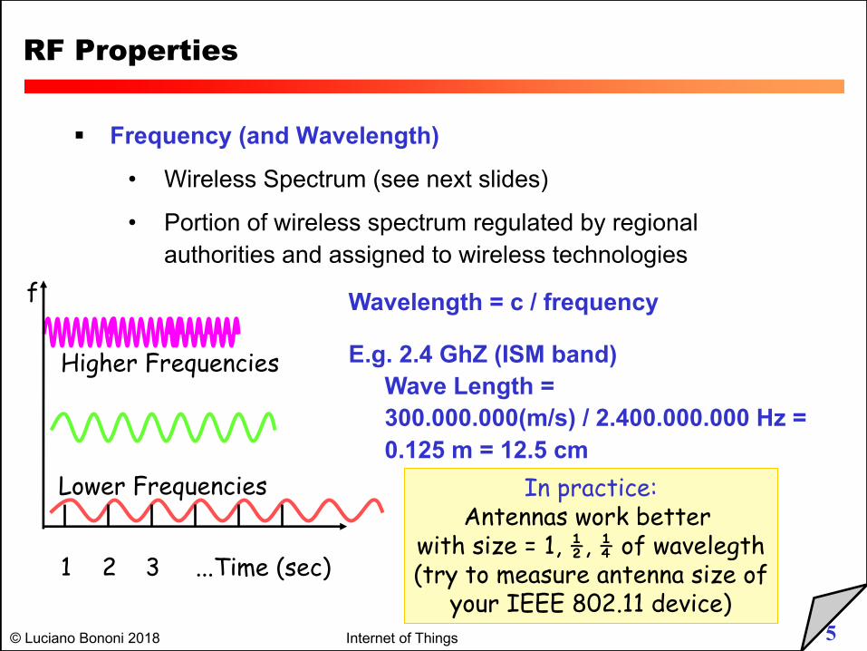
§ Frequency (and Wavelength)
• Wireless Spectrum (see next slides)
• Portion of wireless spectrum regulated by regional authorities and assigned to wireless technologies
2 3 ...Time (sec)
Higher Frequencies
Lower Frequencies
1
f Wavelength = c / frequency
E.g. 2.4 GhZ (ISM band)Wave Length = 300.000.000(m/s) / 2.400.000.000 Hz =0.125 m = 12.5 cm
In practice:Antennas work better
with size = 1, ½, ¼ of wavelegth(try to measure antenna size of
your IEEE 802.11 device)
6© Luciano Bononi 2018 Internet of Things
RF propagation
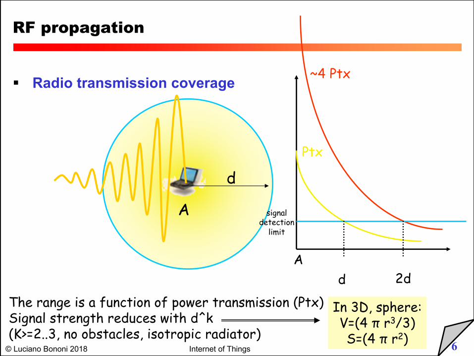
§ Radio transmission coverage
The range is a function of power transmission (Ptx)Signal strength reduces with d^k (K>=2..3, no obstacles, isotropic radiator)
A
d
d 2d
signal detection
limit
Ptx
~4 Ptx
A
In 3D, sphere:V=(4 π r3/3)S=(4 π r2)
7© Luciano Bononi 2018 Internet of Things
Wireless networks’ technology
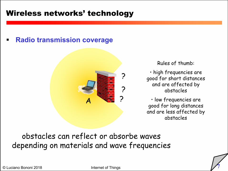
§ Radio transmission coverage
obstacles can reflect or absorbe wavesdepending on materials and wave frequencies
A??
?
Rules of thumb:
• high frequencies are good for short distances
and are affected by abstacles
• low frequencies are good for long distances
and are less affected by abstacles
8© Luciano Bononi 2018 Internet of Things
RF Properties
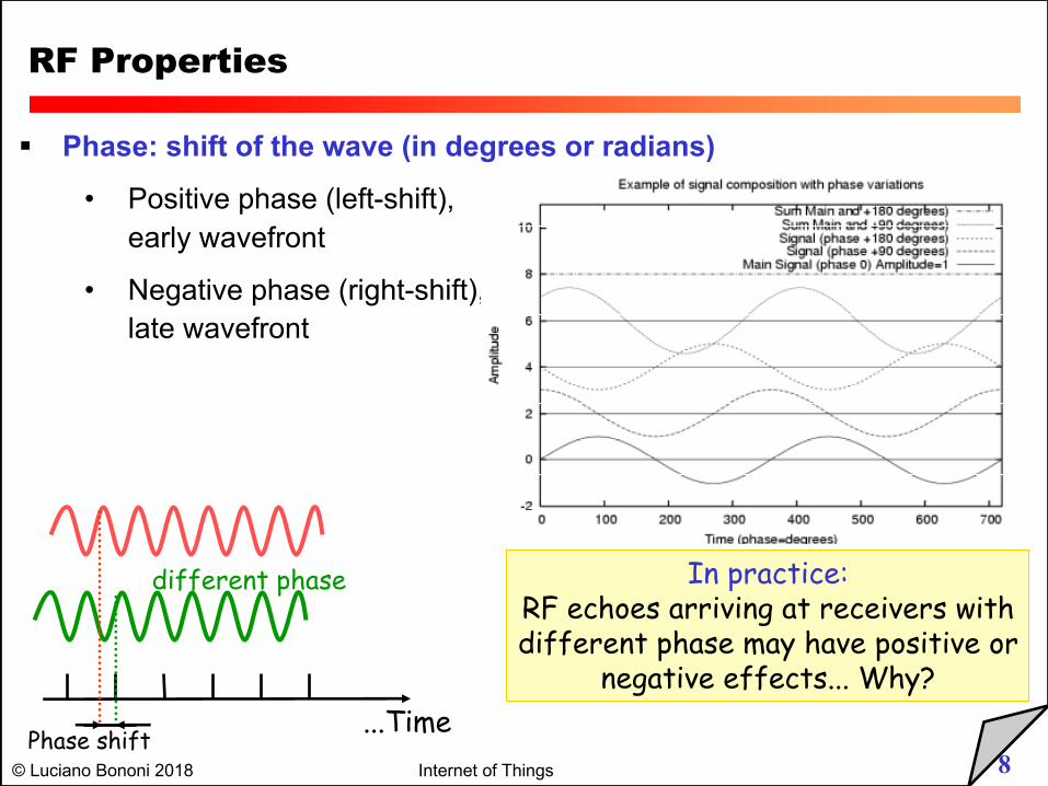
§ Phase: shift of the wave (in degrees or radians)
• Positive phase (left-shift), early wavefront
• Negative phase (right-shift), late wavefront
In practice:RF echoes arriving at receivers withdifferent phase may have positive or
negative effects... Why?
different phase
Phase shift...Time
9© Luciano Bononi 2018 Internet of Things
RF Properties
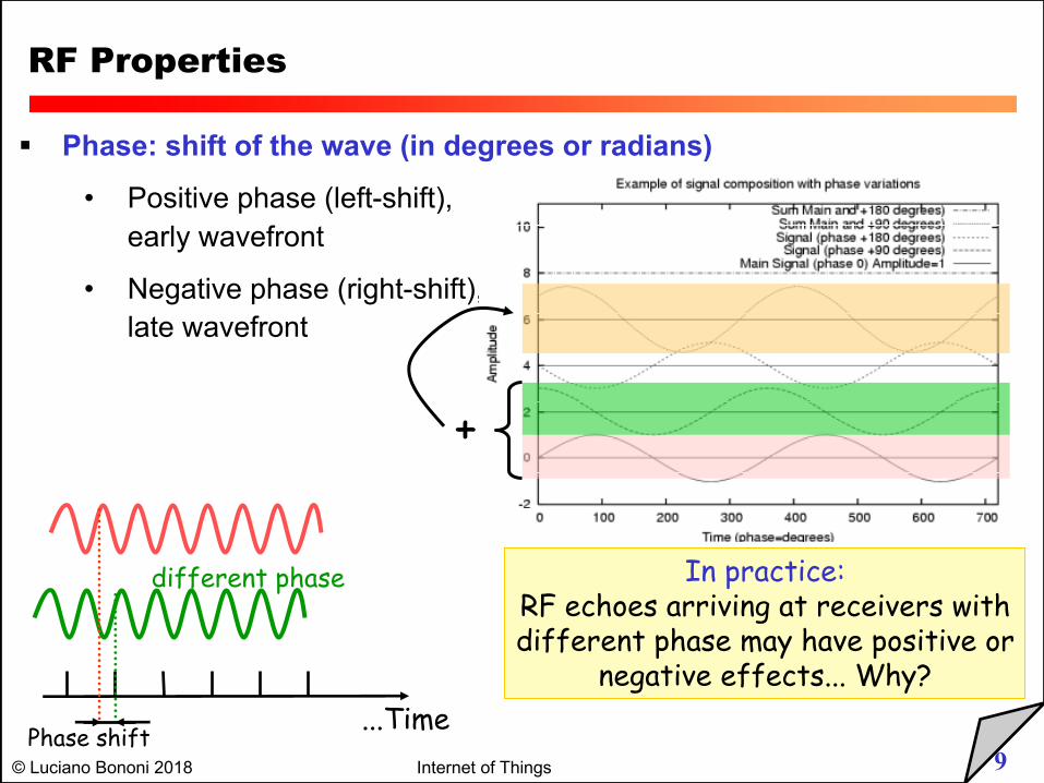
§ Phase: shift of the wave (in degrees or radians)
• Positive phase (left-shift), early wavefront
• Negative phase (right-shift), late wavefront
In practice:RF echoes arriving at receivers withdifferent phase may have positive or
negative effects... Why?
different phase
Phase shift...Time
+
10© Luciano Bononi 2018 Internet of Things
RF Properties
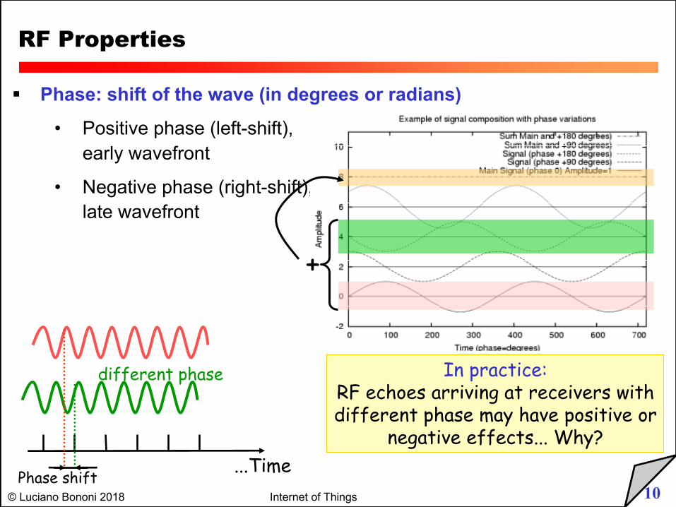
§ Phase: shift of the wave (in degrees or radians)
• Positive phase (left-shift), early wavefront
• Negative phase (right-shift), late wavefront
In practice:RF echoes arriving at receivers withdifferent phase may have positive or
negative effects... Why?
different phase
Phase shift...Time
+
11© Luciano Bononi 2018 Internet of Things
RF Properties
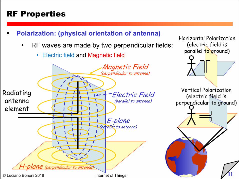
§ Polarization: (physical orientation of antenna)
• RF waves are made by two perpendicular fields:• Electric field and Magnetic field
H-plane (perpendicular to antenna)
E-plane(parallel to antenna)
Radiatingantennaelement
Electric Field(parallel to antenna)
Magnetic Field(perpendicular to antenna)
Vertical Polarization(electric field is
perpendicular to ground)
Horizontal Polarization(electric field is
parallel to ground)
12© Luciano Bononi 2018 Internet of Things
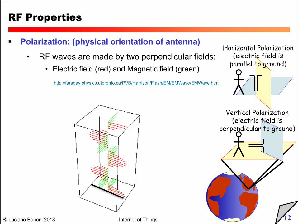
RF Properties
§ Polarization: (physical orientation of antenna)
• RF waves are made by two perpendicular fields:• Electric field (red) and Magnetic field (green)
http://faraday.physics.utoronto.ca/PVB/Harrison/Flash/EM/EMWave/EMWave.html
Vertical Polarization(electric field is
perpendicular to ground)
Horizontal Polarization(electric field is
parallel to ground)
13© Luciano Bononi 2018 Internet of Things
RF Properties
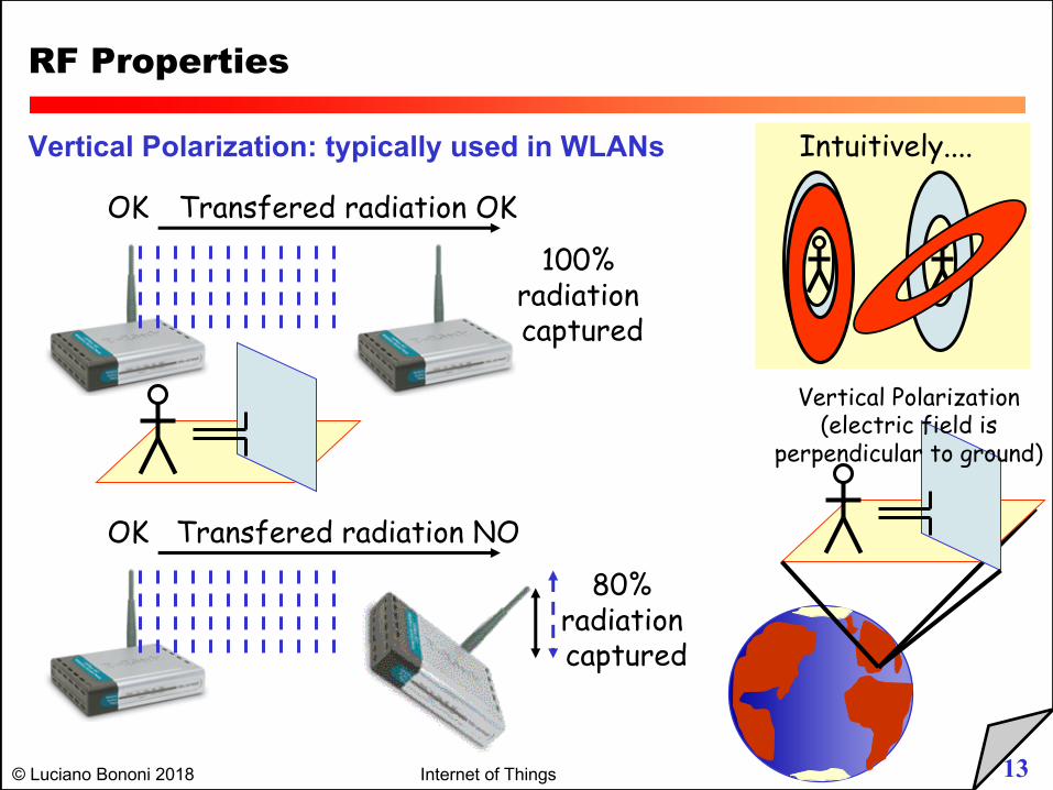
Vertical Polarization: typically used in WLANs
Vertical Polarization(electric field is
perpendicular to ground)
OK Transfered radiation OK
100% radiation captured
OK Transfered radiation NO
80% radiation captured
Intuitively....
14© Luciano Bononi 2018 Internet of Things
RF Properties
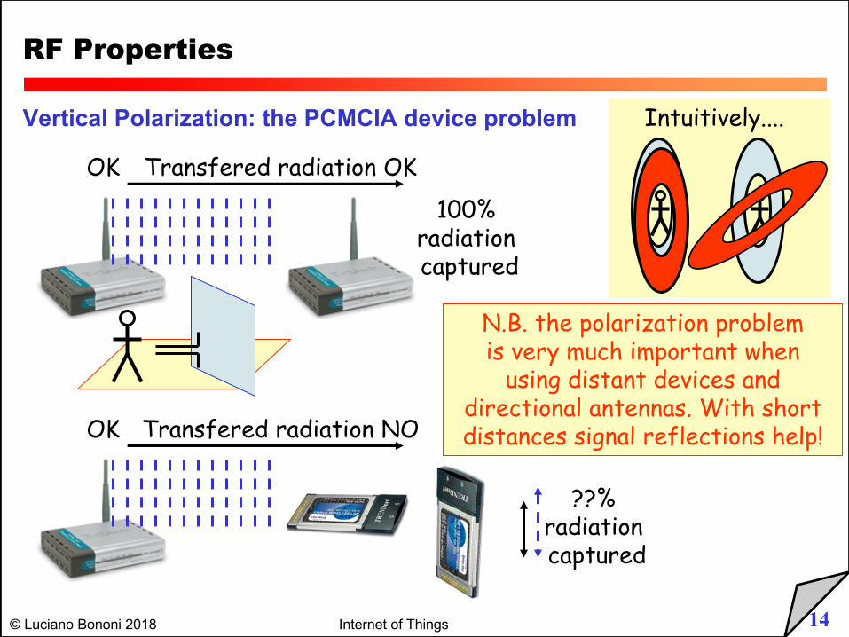
Vertical Polarization: the PCMCIA device problem
OK Transfered radiation OK
100% radiation captured
OK Transfered radiation NO
??% radiation captured
Intuitively....
N.B. the polarization problemis very much important when
using distant devices and directional antennas. With short distances signal reflections help!
15© Luciano Bononi 2018 Internet of Things
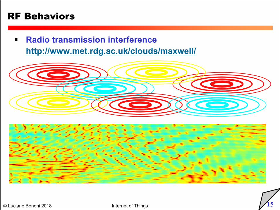
RF Behaviors
§ Radio transmission interferencehttp://www.met.rdg.ac.uk/clouds/maxwell/
16© Luciano Bononi 2018 Internet of Things
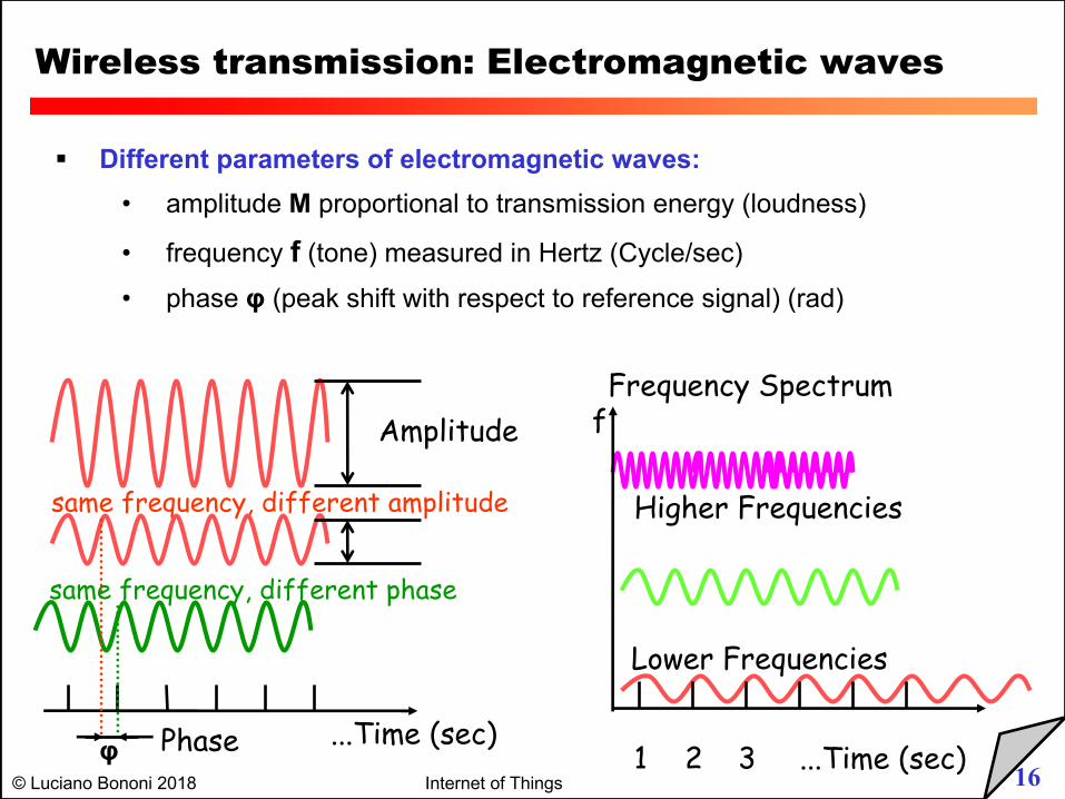
Wireless transmission: Electromagnetic waves
§ Different parameters of electromagnetic waves:• amplitude M proportional to transmission energy (loudness)
• frequency f (tone) measured in Hertz (Cycle/sec)• phase φ (peak shift with respect to reference signal) (rad)
Frequency Spectrum
same frequency, different amplitude
2 3 ...Time (sec)
Higher Frequencies
Lower Frequencies
1
Amplitude
same frequency, different phase
φ Phase ...Time (sec)
f
17© Luciano Bononi 2018 Internet of Things
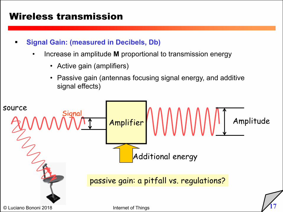
Wireless transmission
§ Signal Gain: (measured in Decibels, Db)• Increase in amplitude M proportional to transmission energy
• Active gain (amplifiers)• Passive gain (antennas focusing signal energy, and additive
signal effects)
SignalAmplitudeAmplifier
Additional energy
source
passive gain: a pitfall vs. regulations?
18© Luciano Bononi 2018 Internet of Things
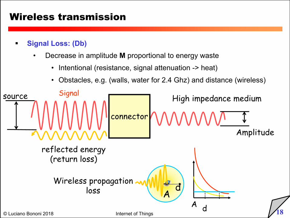
Wireless transmission
§ Signal Loss: (Db)• Decrease in amplitude M proportional to energy waste
• Intentional (resistance, signal attenuation -> heat)
• Obstacles, e.g. (walls, water for 2.4 Ghz) and distance (wireless)
Signal
Amplitude
connector
reflected energy(return loss)
source High impedance medium
Ad
dA
Wireless propagationloss
19© Luciano Bononi 2018 Internet of Things
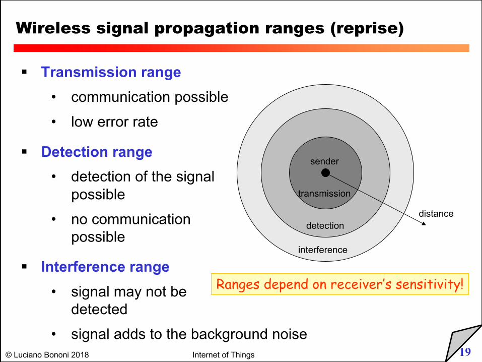
Wireless signal propagation ranges (reprise)
distance
sender
transmission
detection
interference
§ Transmission range• communication possible• low error rate
§ Detection range• detection of the signal
possible• no communication
possible
§ Interference range• signal may not be
detected • signal adds to the background noise
Ranges depend on receiver’s sensitivity!
20© Luciano Bononi 2018 Internet of Things
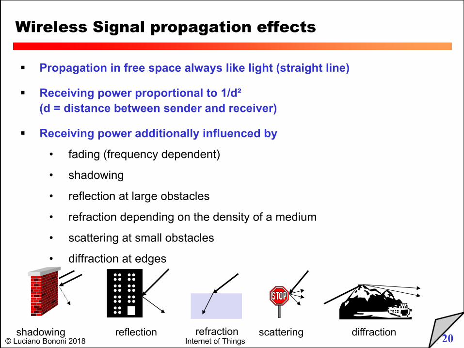
Wireless Signal propagation effects
§ Propagation in free space always like light (straight line)
§ Receiving power proportional to 1/d² (d = distance between sender and receiver)
§ Receiving power additionally influenced by
• fading (frequency dependent)
• shadowing
• reflection at large obstacles
• refraction depending on the density of a medium
• scattering at small obstacles
• diffraction at edges
reflection scattering diffractionshadowing refraction
21© Luciano Bononi 2018 Internet of Things
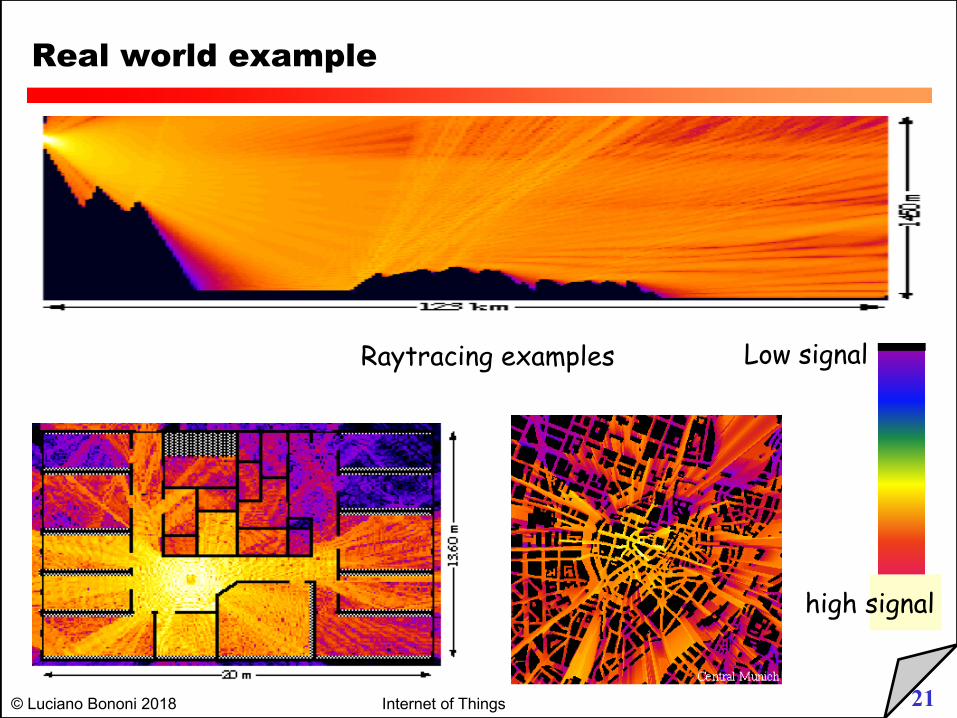
Real world example
Raytracing examples Low signal
high signal
22© Luciano Bononi 2018 Internet of Things
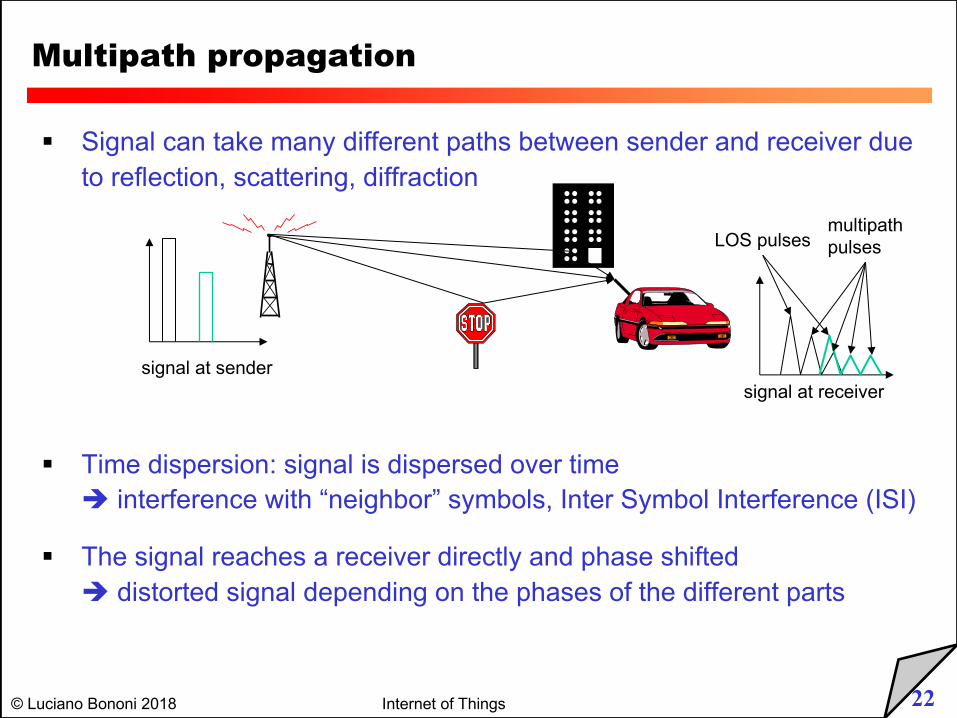
§ Signal can take many different paths between sender and receiver due to reflection, scattering, diffraction
§ Time dispersion: signal is dispersed over timeè interference with “neighbor” symbols, Inter Symbol Interference (ISI)
§ The signal reaches a receiver directly and phase shiftedè distorted signal depending on the phases of the different parts
Multipath propagation
signal at sendersignal at receiver
LOS pulsesmultipathpulses
23© Luciano Bononi 2018 Internet of Things
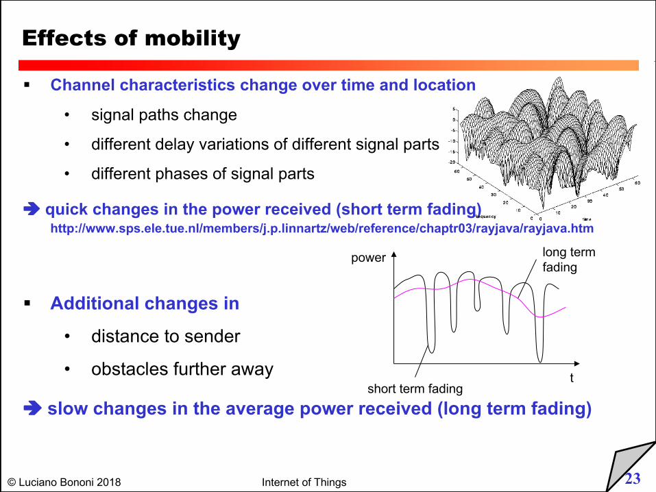
Effects of mobility
§ Channel characteristics change over time and location
• signal paths change
• different delay variations of different signal parts
• different phases of signal parts
è quick changes in the power received (short term fading)http://www.sps.ele.tue.nl/members/j.p.linnartz/web/reference/chaptr03/rayjava/rayjava.htm
§ Additional changes in
• distance to sender
• obstacles further away
è slow changes in the average power received (long term fading)short term fading
long termfading
t
power
24© Luciano Bononi 2018 Internet of Things
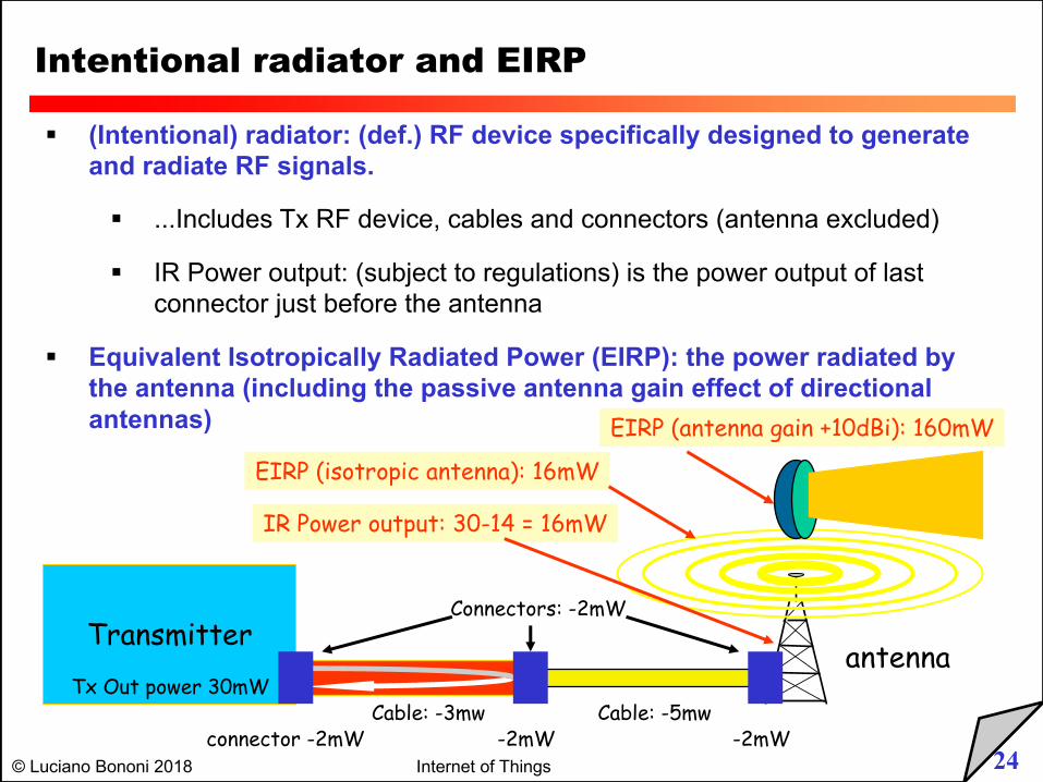
Intentional radiator and EIRP
§ (Intentional) radiator: (def.) RF device specifically designed to generate and radiate RF signals.
§ ...Includes Tx RF device, cables and connectors (antenna excluded)
§ IR Power output: (subject to regulations) is the power output of last connector just before the antenna
§ Equivalent Isotropically Radiated Power (EIRP): the power radiated by the antenna (including the passive antenna gain effect of directional antennas)
Transmitterantenna
Tx Out power 30mWCable: -5mw
Connectors: -2mW
connector -2mW -2mW -2mWCable: -3mw
IR Power output: 30-14 = 16mW
EIRP (isotropic antenna): 16mW
EIRP (antenna gain +10dBi): 160mW
25© Luciano Bononi 2018 Internet of Things
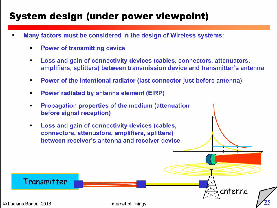
System design (under power viewpoint)
§ Many factors must be considered in the design of Wireless systems:
§ Power of transmitting device
§ Loss and gain of connectivity devices (cables, connectors, attenuators, amplifiers, splitters) between transmission device and transmitter’s antenna
§ Power of the intentional radiator (last connector just before antenna)
§ Power radiated by antenna element (EIRP)
§ Propagation properties of the medium (attenuation before signal reception)
§ Loss and gain of connectivity devices (cables, connectors, attenuators, amplifiers, splitters) between receiver’s antenna and receiver device.
antennaTransmitter
26© Luciano Bononi 2018 Internet of Things
Power measurement
§ WATT: electric power unit
§ 1 Watt = 1 Ampere * 1 Volt (P=V*I) also P= R*I^2 and P = L/t
§ Current (ampere) is the amount of charge (electrons) flowing as current in a wire
§ Voltage (Volt) is the “pressure” applied to the flow of charge
§ Resistance (impedance) is the obstacle to current flow
§ Power is the energy needed (in a given time unit) to apply a given “pressure” to a given “amount of charge”, by resulting in a flow of current.
§ Watt and dBm are units used for absolute power measurement
§ Typical RF power for WLANs:
§ AP: 30..100 mW (up to 250 mW outdoor), PCMCIA: 15..30 mW
27© Luciano Bononi 2018 Internet of Things
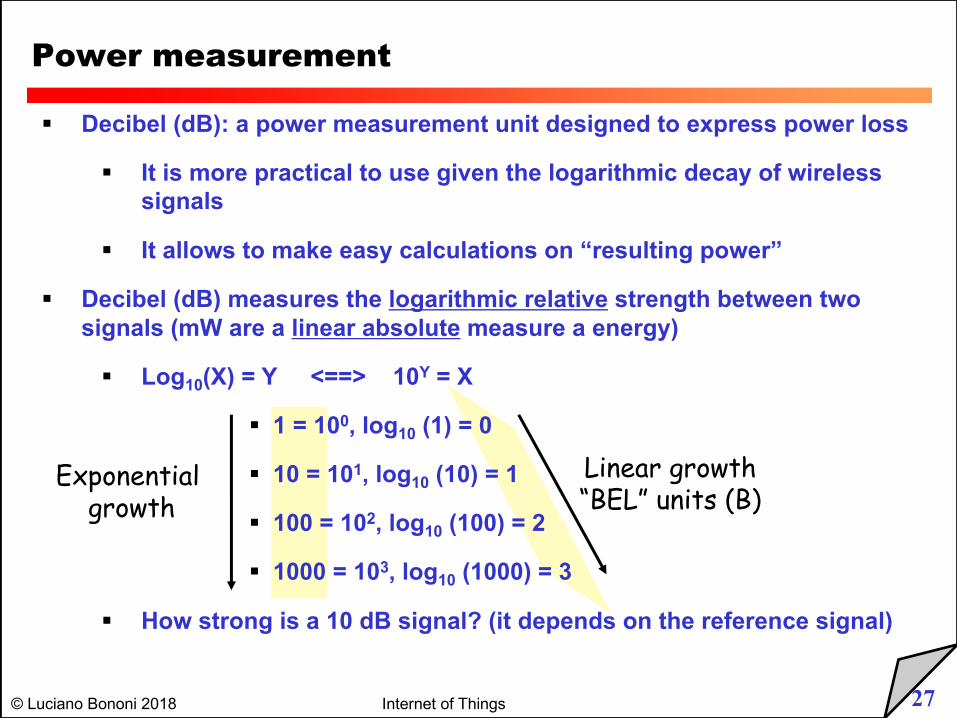
§ Decibel (dB): a power measurement unit designed to express power loss
§ It is more practical to use given the logarithmic decay of wireless signals
§ It allows to make easy calculations on “resulting power”
§ Decibel (dB) measures the logarithmic relative strength between two signals (mW are a linear absolute measure a energy)
§ Log10(X) = Y <==> 10Y = X
§ 1 = 100, log10 (1) = 0
§ 10 = 101, log10 (10) = 1
§ 100 = 102, log10 (100) = 2
§ 1000 = 103, log10 (1000) = 3
§ How strong is a 10 dB signal? (it depends on the reference signal)
Power measurement
Linear growth“BEL” units (B)
Exponentialgrowth
28© Luciano Bononi 2018 Internet of Things
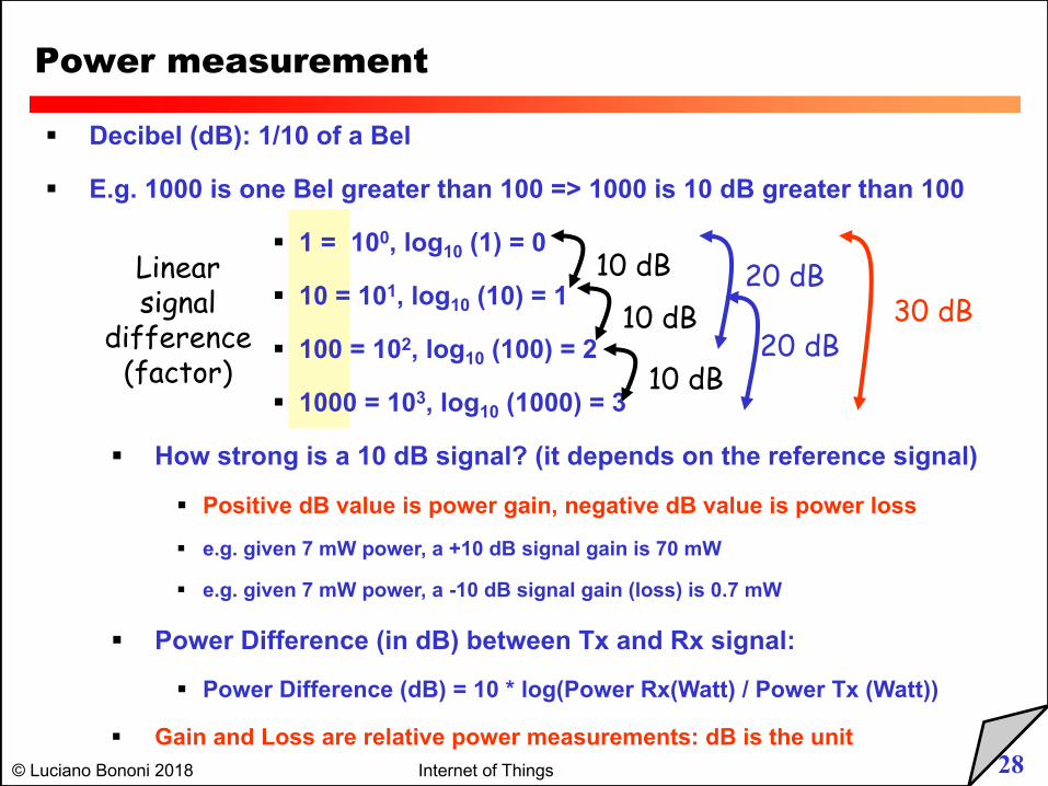
§ Decibel (dB): 1/10 of a Bel
§ E.g. 1000 is one Bel greater than 100 => 1000 is 10 dB greater than 100
§ 1 = 100, log10 (1) = 0
§ 10 = 101, log10 (10) = 1
§ 100 = 102, log10 (100) = 2
§ 1000 = 103, log10 (1000) = 3
§ How strong is a 10 dB signal? (it depends on the reference signal)
§ Positive dB value is power gain, negative dB value is power loss
§ e.g. given 7 mW power, a +10 dB signal gain is 70 mW
§ e.g. given 7 mW power, a -10 dB signal gain (loss) is 0.7 mW
§ Power Difference (in dB) between Tx and Rx signal:
§ Power Difference (dB) = 10 * log(Power Rx(Watt) / Power Tx (Watt))
§ Gain and Loss are relative power measurements: dB is the unit
Power measurement
10 dB
10 dB
10 dB
20 dB
20 dB30 dB
Linearsignal
difference(factor)
29© Luciano Bononi 2018 Internet of Things
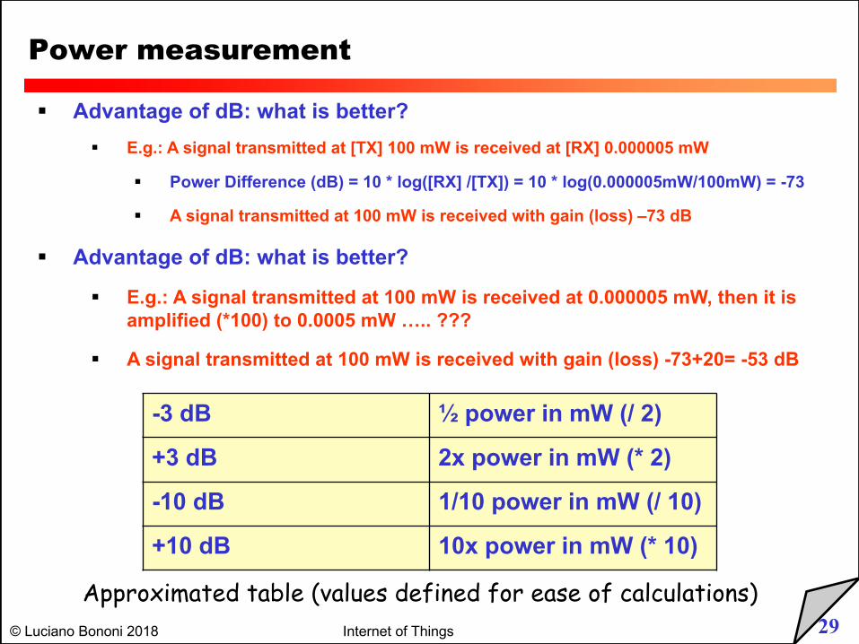
§ Advantage of dB: what is better?
§ E.g.: A signal transmitted at [TX] 100 mW is received at [RX] 0.000005 mW
§ Power Difference (dB) = 10 * log([RX] /[TX]) = 10 * log(0.000005mW/100mW) = -73
§ A signal transmitted at 100 mW is received with gain (loss) –73 dB
§ Advantage of dB: what is better?
§ E.g.: A signal transmitted at 100 mW is received at 0.000005 mW, then it is amplified (*100) to 0.0005 mW ….. ???
§ A signal transmitted at 100 mW is received with gain (loss) -73+20= -53 dB
Power measurement
-3 dB ½ power in mW (/ 2)
+3 dB 2x power in mW (* 2)
-10 dB 1/10 power in mW (/ 10)
+10 dB 10x power in mW (* 10)
Approximated table (values defined for ease of calculations)
30© Luciano Bononi 2018 Internet of Things
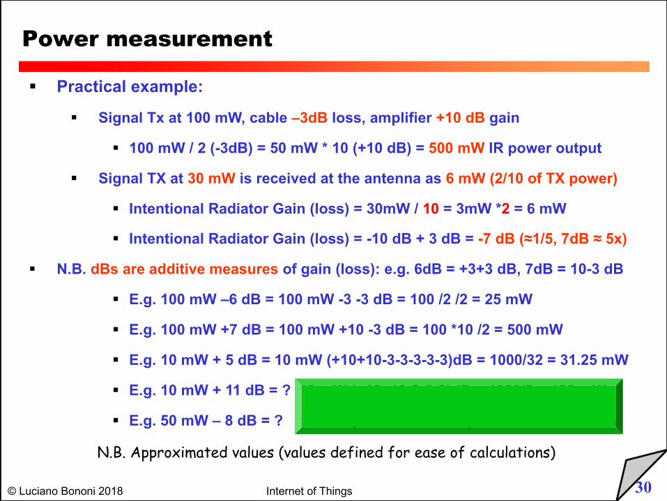
§ Practical example:
§ Signal Tx at 100 mW, cable –3dB loss, amplifier +10 dB gain
§ 100 mW / 2 (-3dB) = 50 mW * 10 (+10 dB) = 500 mW IR power output
§ Signal TX at 30 mW is received at the antenna as 6 mW (2/10 of TX power)
§ Intentional Radiator Gain (loss) = 30mW / 10 = 3mW *2 = 6 mW
§ Intentional Radiator Gain (loss) = -10 dB + 3 dB = -7 dB (≈1/5, 7dB ≈ 5x)
§ N.B. dBs are additive measures of gain (loss): e.g. 6dB = +3+3 dB, 7dB = 10-3 dB
§ E.g. 100 mW –6 dB = 100 mW -3 -3 dB = 100 /2 /2 = 25 mW
§ E.g. 100 mW +7 dB = 100 mW +10 -3 dB = 100 *10 /2 = 500 mW
§ E.g. 10 mW + 5 dB = 10 mW (+10+10-3-3-3-3-3)dB = 1000/32 = 31.25 mW
§ E.g. 10 mW + 11 dB = ? 10 mW (+10+10-3-3-3)dB = 1000/8 = 125 mW
§ E.g. 50 mW – 8 dB = ? 50 mW (-10-10+3+3+3+3)dB = 800/100 = 8 mW
Power measurement
N.B. Approximated values (values defined for ease of calculations)
31© Luciano Bononi 2018 Internet of Things
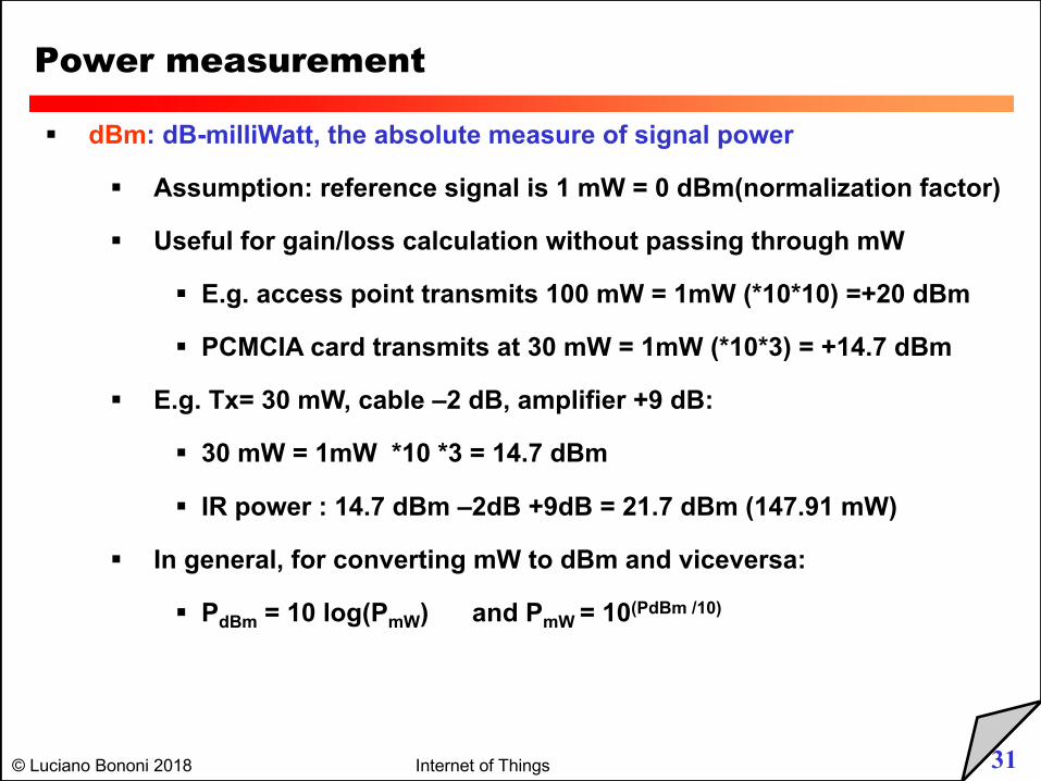
§ dBm: dB-milliWatt, the absolute measure of signal power
§ Assumption: reference signal is 1 mW = 0 dBm(normalization factor)
§ Useful for gain/loss calculation without passing through mW
§ E.g. access point transmits 100 mW = 1mW (*10*10) =+20 dBm
§ PCMCIA card transmits at 30 mW = 1mW (*10*3) = +14.7 dBm
§ E.g. Tx= 30 mW, cable –2 dB, amplifier +9 dB:
§ 30 mW = 1mW *10 *3 = 14.7 dBm
§ IR power : 14.7 dBm –2dB +9dB = 21.7 dBm (147.91 mW)
§ In general, for converting mW to dBm and viceversa:
§ PdBm = 10 log(PmW) and PmW = 10(PdBm /10)
Power measurement
32© Luciano Bononi 2018 Internet of Things
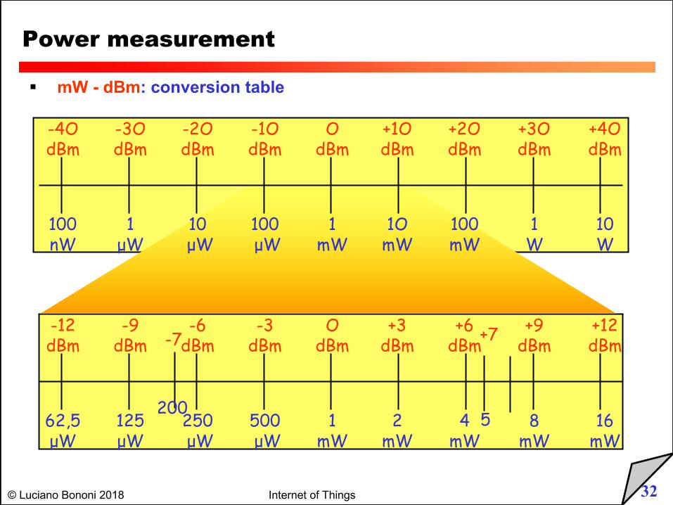
§ mW - dBm: conversion table
Power measurement
OdBm
+1OdBm
+2OdBm
+3OdBm
+4OdBm
-1OdBm
-2OdBm
-3OdBm
-4OdBm
1mW
1OmW
100mW
1W
10W
100µW
10µW
1µW
100nW
OdBm
+3dBm
+6dBm
+9dBm
+12dBm
-3dBm
-6dBm
-9dBm
-12dBm
1mW
2mW
4mW
8mW
16mW
500µW
250µW
125µW
62,5µW
-7
200
+7
5
33© Luciano Bononi 2018 Internet of Things
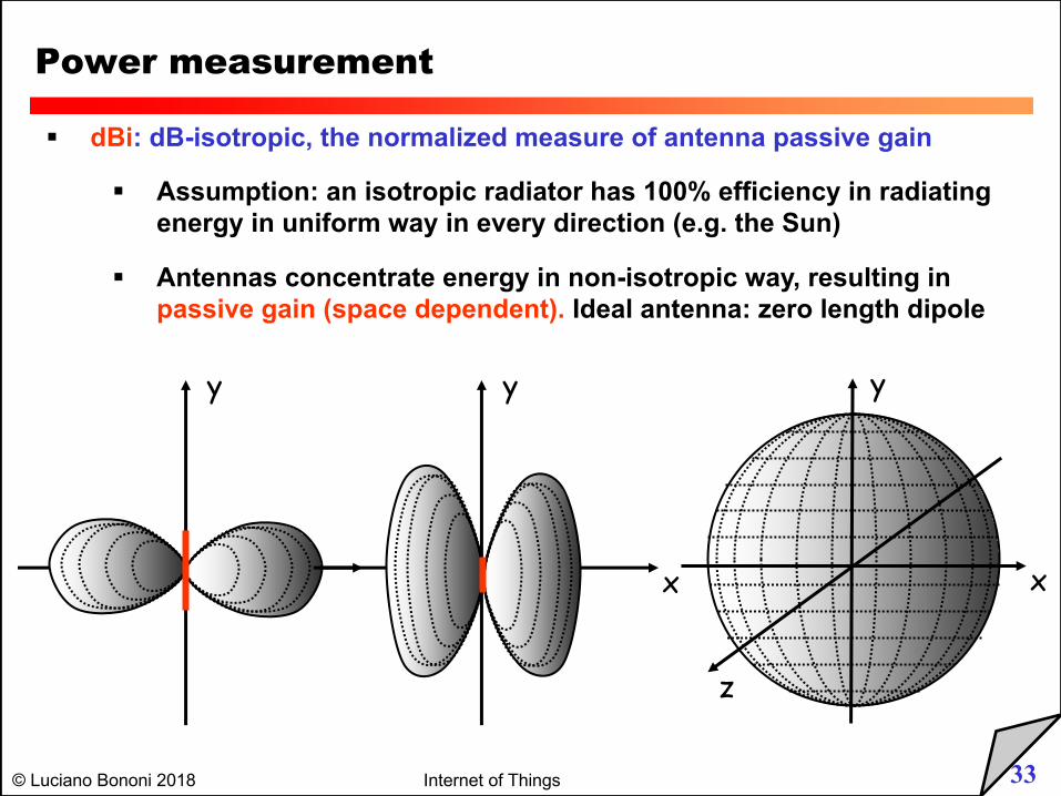
§ dBi: dB-isotropic, the normalized measure of antenna passive gain
§ Assumption: an isotropic radiator has 100% efficiency in radiating energy in uniform way in every direction (e.g. the Sun)
§ Antennas concentrate energy in non-isotropic way, resulting in passive gain (space dependent). Ideal antenna: zero length dipole
Power measurement
x
y
z
y
x
y
x
34© Luciano Bononi 2018 Internet of Things
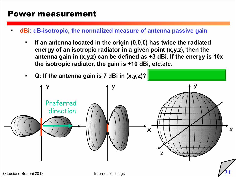
§ dBi: dB-isotropic, the normalized measure of antenna passive gain
§ If an antenna located in the origin (0,0,0) has twice the radiated energy of an isotropic radiator in a given point (x,y,z), then the antenna gain in (x,y,z) can be defined as +3 dBi. If the energy is 10x the isotropic radiator, the gain is +10 dBi, etc.etc.
§ Q: If the antenna gain is 7 dBi in (x,y,z)? (A: 5x isotropic energy)
Power measurement
x
y
z
y
x
y
x
Preferred direction
35© Luciano Bononi 2018 Internet of Things
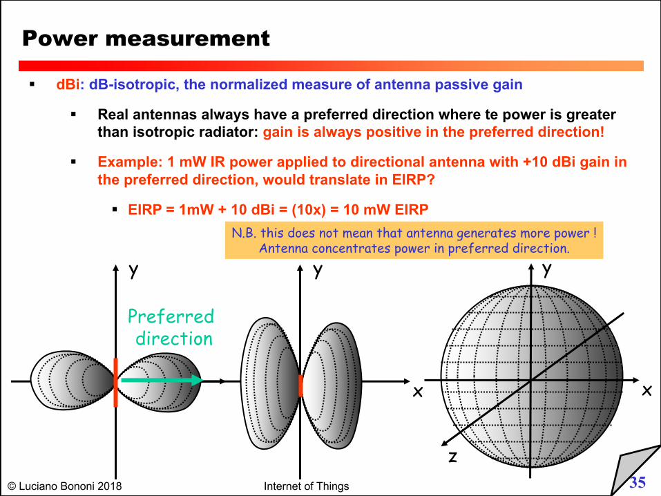
§ dBi: dB-isotropic, the normalized measure of antenna passive gain
§ Real antennas always have a preferred direction where te power is greater than isotropic radiator: gain is always positive in the preferred direction!
§ Example: 1 mW IR power applied to directional antenna with +10 dBi gain in the preferred direction, would translate in EIRP?
§ EIRP = 1mW + 10 dBi = (10x) = 10 mW EIRP
Power measurement
x
y
z
y
x
y
x
Preferred direction
N.B. this does not mean that antenna generates more power !Antenna concentrates power in preferred direction.
36© Luciano Bononi 2018 Internet of Things
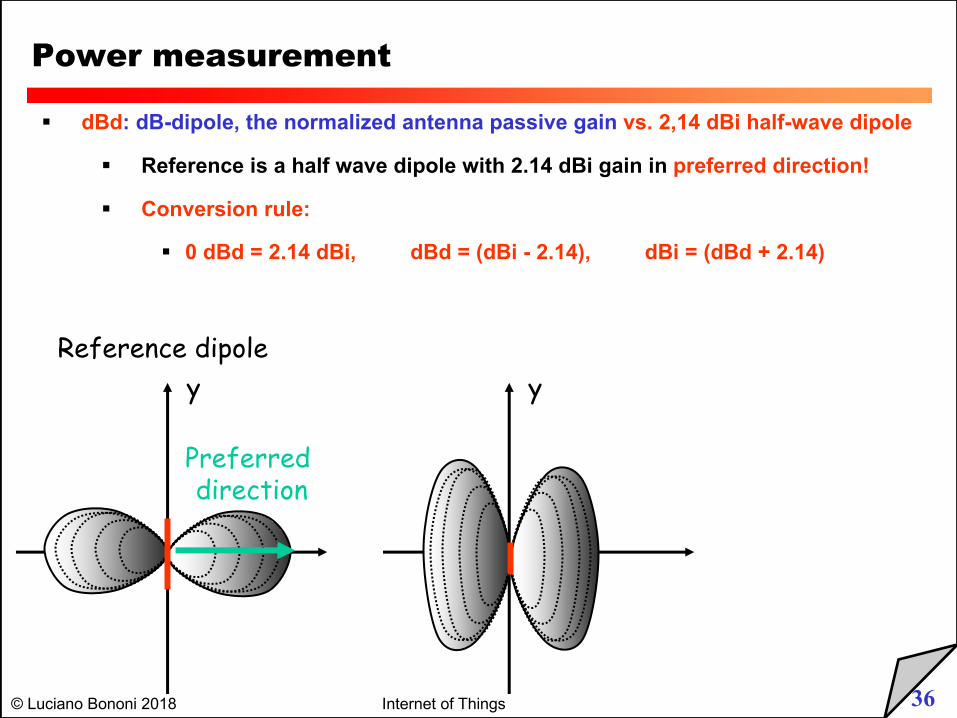
§ dBd: dB-dipole, the normalized antenna passive gain vs. 2,14 dBi half-wave dipole
§ Reference is a half wave dipole with 2.14 dBi gain in preferred direction!
§ Conversion rule:
§ 0 dBd = 2.14 dBi, dBd = (dBi - 2.14), dBi = (dBd + 2.14)
Power measurement
y y
x
Preferred direction
Reference dipole
37© Luciano Bononi 2018 Internet of Things
§ Illustration of general issues
§ Convert electrical energy in RF waves (transmission), and RF waves in eletrical energy (reception)
§ Size of antenna is related to RF frequency of transmission and reception
§ Shape (structure) of the antenna is related to RF radiation pattern
§ Radiation patterns of different antenna types
§ Positioning antennas
§ Maximum coverage of workspace
§ Security issues
§ Real antenna types: omni-directional, semi-directional, highly-directional
Antennas
38© Luciano Bononi 2018 Internet of Things
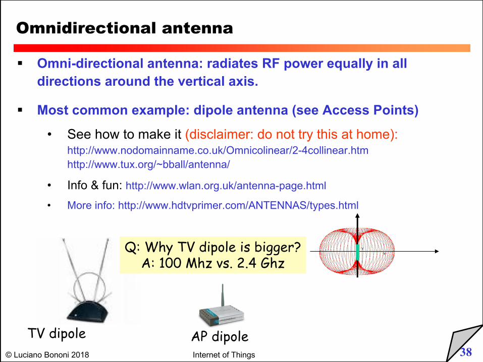
Omnidirectional antenna
§ Omni-directional antenna: radiates RF power equally in all directions around the vertical axis.
§ Most common example: dipole antenna (see Access Points)
• See how to make it (disclaimer: do not try this at home):http://www.nodomainname.co.uk/Omnicolinear/2-4collinear.htmhttp://www.tux.org/~bball/antenna/
• Info & fun: http://www.wlan.org.uk/antenna-page.html
• More info: http://www.hdtvprimer.com/ANTENNAS/types.html
TV dipole AP dipole
Q: Why TV dipole is bigger?A: 100 Mhz vs. 2.4 Ghz
39© Luciano Bononi 2018 Internet of Things
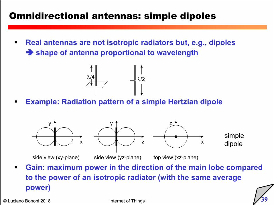
Omnidirectional antennas: simple dipoles
§ Real antennas are not isotropic radiators but, e.g., dipoles è shape of antenna proportional to wavelength
§ Example: Radiation pattern of a simple Hertzian dipole
§ Gain: maximum power in the direction of the main lobe compared to the power of an isotropic radiator (with the same average power)
side view (xy-plane)
x
y
side view (yz-plane)
z
y
top view (xz-plane)
x
z
simpledipole
l/4 l/2
40© Luciano Bononi 2018 Internet of Things
Omnidirectional antennas: simple dipoles
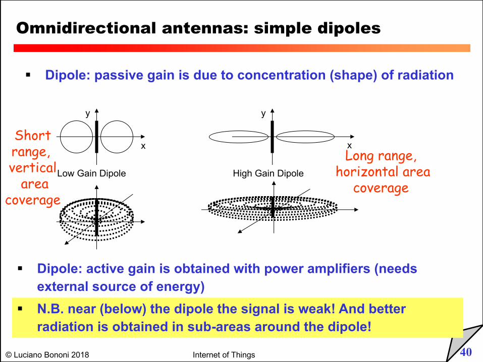
§ Dipole: passive gain is due to concentration (shape) of radiation
Low Gain Dipole
x
y
High Gain Dipole
x
y
§ Dipole: active gain is obtained with power amplifiers (needs external source of energy)
§ N.B. near (below) the dipole the signal is weak! And better radiation is obtained in sub-areas around the dipole!
Long range,horizontal area
coverage
Shortrange, vertical
areacoverage
41© Luciano Bononi 2018 Internet of Things
Omnidirectional antennas: simple dipoles
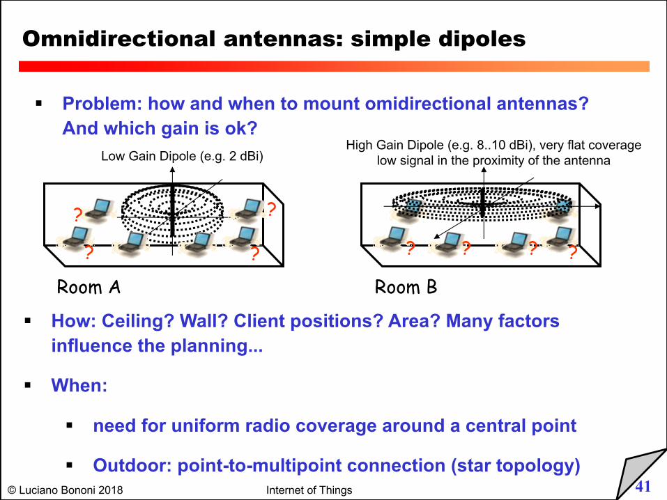
§ Problem: how and when to mount omidirectional antennas? And which gain is ok?
Low Gain Dipole (e.g. 2 dBi)High Gain Dipole (e.g. 8..10 dBi), very flat coverage
low signal in the proximity of the antenna
§ How: Ceiling? Wall? Client positions? Area? Many factors influence the planning...
§ When:
§ need for uniform radio coverage around a central point
§ Outdoor: point-to-multipoint connection (star topology)
Room A Room B
? ? ? ? ? ?
? ?
42© Luciano Bononi 2018 Internet of Things
Omnidirectional antennas: simple dipoles
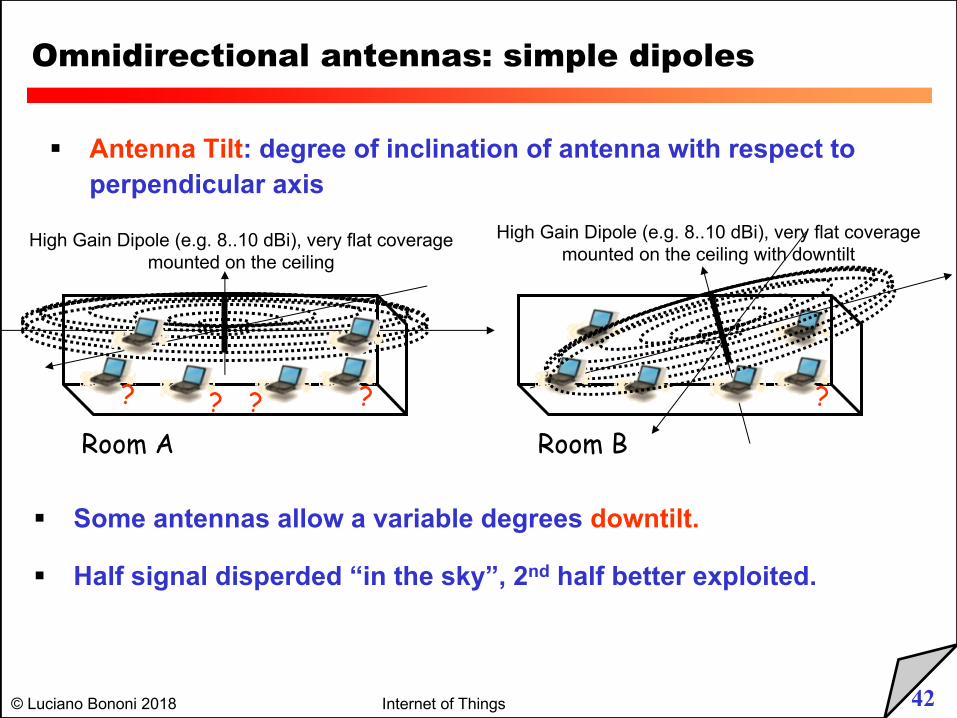
§ Antenna Tilt: degree of inclination of antenna with respect to perpendicular axis
High Gain Dipole (e.g. 8..10 dBi), very flat coveragemounted on the ceiling with downtilt
§ Some antennas allow a variable degrees downtilt.
§ Half signal disperded “in the sky”, 2nd half better exploited.
Room A Room B
? ?? ??
High Gain Dipole (e.g. 8..10 dBi), very flat coveragemounted on the ceiling
43© Luciano Bononi 2018 Internet of Things
Semi-directional antennas
side view (xy-plane) Patch
x
y
side view (yz-plane)
z
y
top view (xz-plane) Yagi
x
z
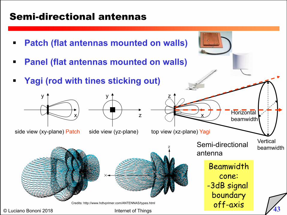
§ Patch (flat antennas mounted on walls)
§ Panel (flat antennas mounted on walls)
§ Yagi (rod with tines sticking out)
Semi-directionalantenna
Verticalbeamwidth
Horizontalbeamwidth
Beamwidthcone:
-3dB signal boundaryoff-axisCredits: http://www.hdtvprimer.com/ANTENNAS/types.html
44© Luciano Bononi 2018 Internet of Things
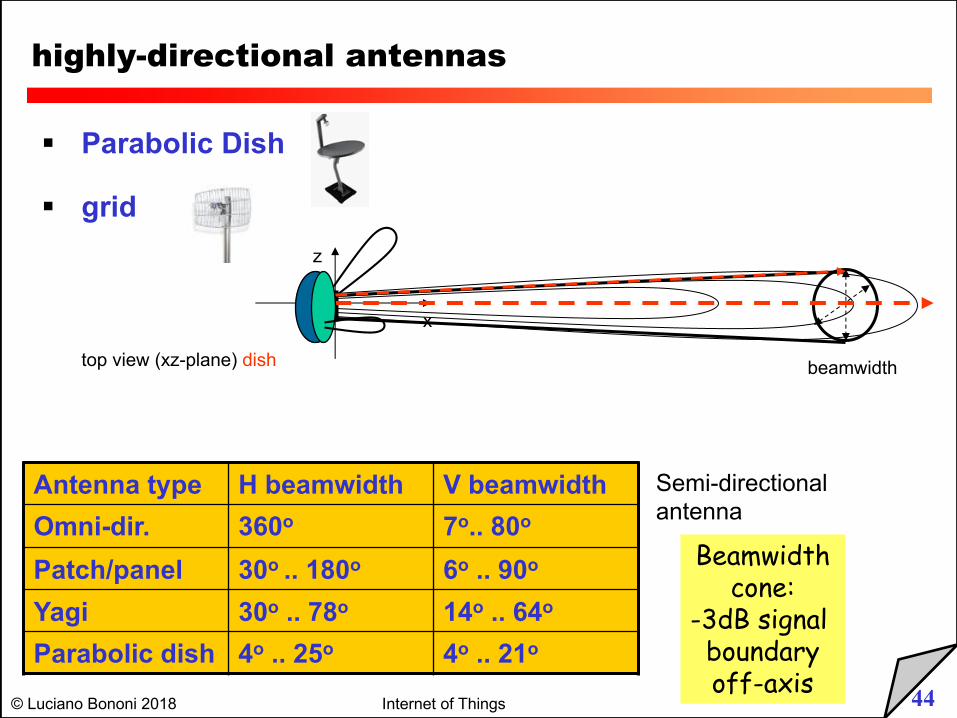
highly-directional antennas
top view (xz-plane) dish
x
z
§ Parabolic Dish
§ grid
Semi-directionalantenna
beamwidth
Beamwidthcone:
-3dB signal boundaryoff-axis
Antenna type H beamwidth V beamwidthOmni-dir. 360o 7o.. 80o
Patch/panel 30o .. 180o 6o .. 90o
Yagi 30o .. 78o 14o .. 64o
Parabolic dish 4o .. 25o 4o .. 21o
45© Luciano Bononi 2018 Internet of Things
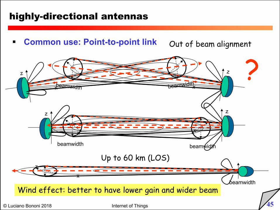
highly-directional antennas
§ Common use: Point-to-point link
x
z
beamwidthx
z
beamwidth
x
z
beamwidth
x
z
beamwidth
Out of beam alignment
Up to 60 km (LOS)
?
xz
beamwidthWind effect: better to have lower gain and wider beam
46© Luciano Bononi 2018 Internet of Things
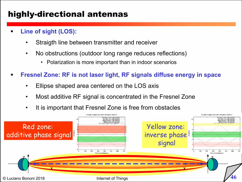
highly-directional antennas
§ Line of sight (LOS):
• Straigth line between transmitter and receiver
• No obstructions (outdoor long range reduces reflections)• Polarization is more important than in indoor scenarios
§ Fresnel Zone: RF is not laser light, RF signals diffuse energy in space
• Ellipse shaped area centered on the LOS axis
• Most additive RF signal is concentrated in the Fresnel Zone
• It is important that Fresnel Zone is free from obstacles
x
z
x
z
Red zone: additive phase signal
Yellow zone: inverse phase
signal
47© Luciano Bononi 2018 Internet of Things
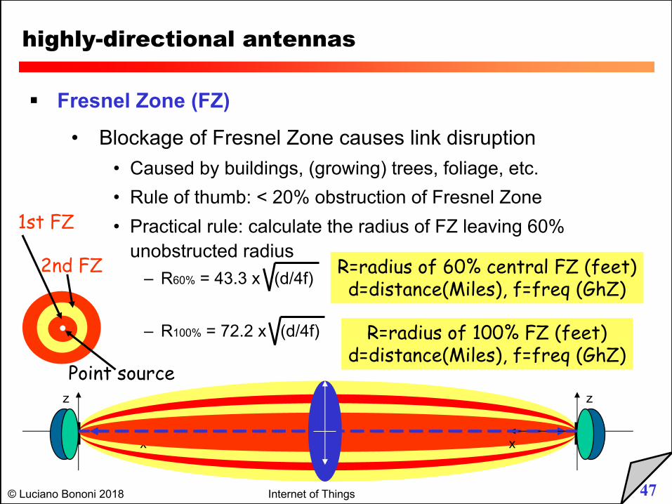
highly-directional antennas
§ Fresnel Zone (FZ)
• Blockage of Fresnel Zone causes link disruption
• Caused by buildings, (growing) trees, foliage, etc.
• Rule of thumb: < 20% obstruction of Fresnel Zone
• Practical rule: calculate the radius of FZ leaving 60%
unobstructed radius
– R60% = 43.3 x (d/4f)
– R100% = 72.2 x (d/4f)
x
z
x
z
R=radius of 60% central FZ (feet)d=distance(Miles), f=freq (GhZ)
R=radius of 100% FZ (feet)d=distance(Miles), f=freq (GhZ)
1st FZ
Point source
2nd FZ
48© Luciano Bononi 2018 Internet of Things
highly-directional antennas
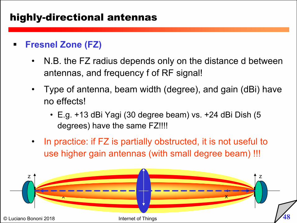
§ Fresnel Zone (FZ)
• N.B. the FZ radius depends only on the distance d between antennas, and frequency f of RF signal!
• Type of antenna, beam width (degree), and gain (dBi) have no effects!
• E.g. +13 dBi Yagi (30 degree beam) vs. +24 dBi Dish (5 degrees) have the same FZ!!!!
• In practice: if FZ is partially obstructed, it is not useful to use higher gain antennas (with small degree beam) !!!
x
z
x
z
49© Luciano Bononi 2018 Internet of Things
xz
xz
highly-directional antennas
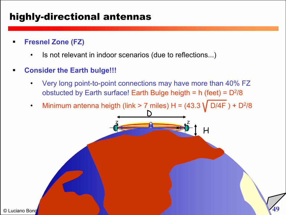
§ Fresnel Zone (FZ)
• Is not relevant in indoor scenarios (due to reflections...)
§ Consider the Earth bulge!!!
• Very long point-to-point connections may have more than 40% FZ obstucted by Earth surface! Earth Bulge heigth = h (feet) = D2/8
• Minimum antenna heigth (link > 7 miles) H = (43.3 D/4F ) + D2/8D
H
50© Luciano Bononi 2018 Internet of Things
Sectorized-directional antennas
top view, 3 sector
x
z
top view, 6 sector
x
z
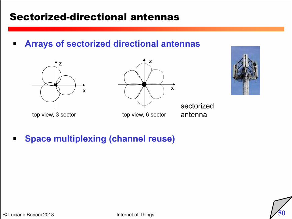
§ Arrays of sectorized directional antennas
sectorizedantenna
§ Space multiplexing (channel reuse)
51© Luciano Bononi 2018 Internet of Things
Azimuth and Elevation antenna charts
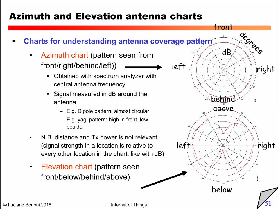
§ Charts for understanding antenna coverage pattern
• Azimuth chart (pattern seen from
front/right/behind/left))
• Obtained with spectrum analyzer with
central antenna frequency
• Signal measured in dB around the
antenna
– E.g. Dipole pattern: almost circular
– E.g. yagi pattern: high in front, low
beside
• N.B. distance and Tx power is not relevant
(signal strength in a location is relative to
every other location in the chart, like with dB)
• Elevation chart (pattern seen
front/below/behind/above)
dB
degrees
front
rightleft
behindabove
below
rightleft
52© Luciano Bononi 2018 Internet of Things
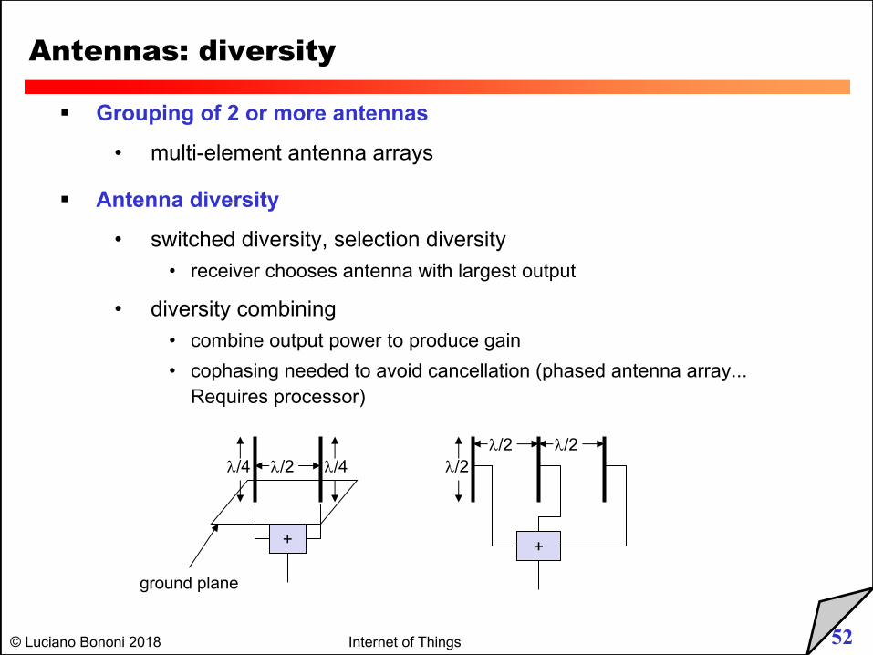
Antennas: diversity
§ Grouping of 2 or more antennas
• multi-element antenna arrays
§ Antenna diversity
• switched diversity, selection diversity• receiver chooses antenna with largest output
• diversity combining• combine output power to produce gain
• cophasing needed to avoid cancellation (phased antenna array... Requires processor)
+
l/4l/2l/4
ground plane
l/2l/2
+
l/2
53© Luciano Bononi 2018 Internet of Things
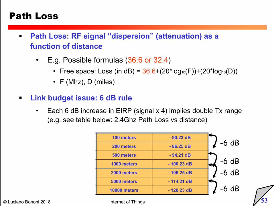
Path Loss
§ Path Loss: RF signal “dispersion” (attenuation) as a function of distance
• E.g. Possible formulas (36.6 or 32.4)• Free space: Loss (in dB) = 36.6+(20*log10(F))+(20*log10(D))
• F (Mhz), D (miles)
§ Link budget issue: 6 dB rule• Each 6 dB increase in EIRP (signal x 4) implies double Tx range
(e.g. see table below: 2.4Ghz Path Loss vs distance)
100 meters - 80.23 dB
200 meters - 86.25 dB
500 meters - 94.21 dB
1000 meters - 100.23 dB
2000 meters - 106.25 dB
5000 meters - 114.21 dB
10000 meters - 120.23 dB
-6 dB
-6 dB-6 dB
-6 dB
54© Luciano Bononi 2018 Internet of Things
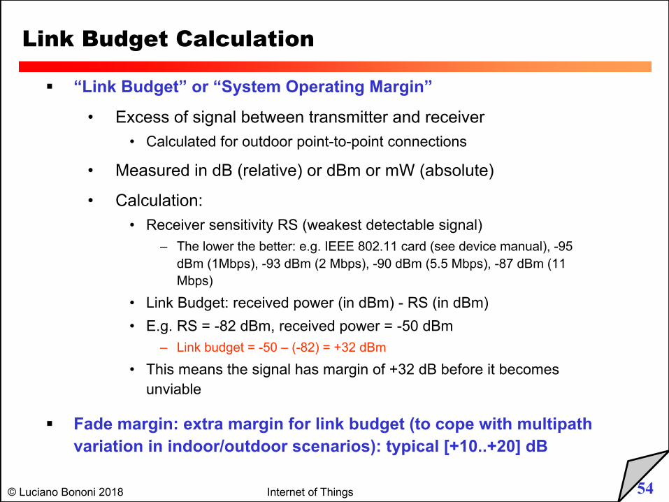
Link Budget Calculation
§ “Link Budget” or “System Operating Margin”
• Excess of signal between transmitter and receiver
• Calculated for outdoor point-to-point connections
• Measured in dB (relative) or dBm or mW (absolute)
• Calculation:
• Receiver sensitivity RS (weakest detectable signal)
– The lower the better: e.g. IEEE 802.11 card (see device manual), -95
dBm (1Mbps), -93 dBm (2 Mbps), -90 dBm (5.5 Mbps), -87 dBm (11
Mbps)
• Link Budget: received power (in dBm) - RS (in dBm)
• E.g. RS = -82 dBm, received power = -50 dBm
– Link budget = -50 – (-82) = +32 dBm
• This means the signal has margin of +32 dB before it becomes
unviable
§ Fade margin: extra margin for link budget (to cope with multipath variation in indoor/outdoor scenarios): typical [+10..+20] dB
55© Luciano Bononi 2018 Internet of Things
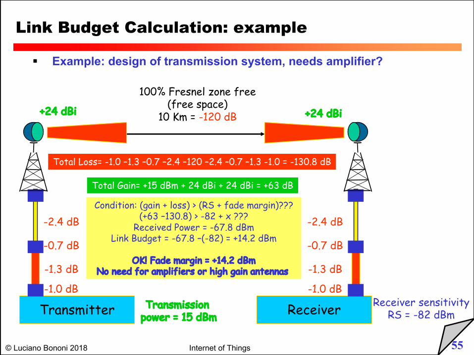
Link Budget Calculation: example
§ Example: design of transmission system, needs amplifier?
Transmitter ReceiverTransmission power = 15 dBm
-1.0 dB
-1.3 dB
-0.7 dB
-2.4 dB
+24 dBi +24 dBi
100% Fresnel zone free(free space)
10 Km = -120 dB
Receiver sensitivityRS = -82 dBm
-1.0 dB
-1.3 dB
-0.7 dB
-2.4 dB
Total Loss= -1.0 –1.3 –0.7 –2.4 –120 –2.4 –0.7 –1.3 -1.0 = -130.8 dB
Total Gain= +15 dBm + 24 dBi + 24 dBi = +63 dB
Condition: (gain + loss) > (RS + fade margin)???(+63 –130.8) > -82 + x ???
Received Power = -67.8 dBmLink Budget = -67.8 –(-82) = +14.2 dBm
OK! Fade margin = +14.2 dBmNo need for amplifiers or high gain antennas