Embed Size (px)
Citation preview
INTERNET OF THINGS APPLICATION GUIDE
designed to be better.™

WWW.LEGRAND.US
THE INTERNET OF THINGS SIMPLY DEFINEDThe world around us is changing rapidly. Technology is becoming increasingly intertwined with our day-to-day routine. With advancements in technology, not only have we become smarter, but so have the devices we rely on. Smarter devices enable a new type of infrastructure, an intelligent network built on the Internet of Things.
Simply defined, the Internet of Things (IoT) is a network of uniquely identifiable endpoints (or “things”) that contain embedded technology to sense, collect and act on data locally or with external environments, without human interaction.
When looking at the landscape of technological innovation over the past 50 years, it’s simple to see how quickly people have adapted to, and begun to rely on, the tools we’ve been given. Now we’re entering a new age, an age where machines and humans work in tandem – an age where we have unprecedented access to automation and where devices can process information and make decisions on their own.
H2H RISE OF AVAILABILITY
H2M RISE OF REACH
M2H RISE OF MOBILITY
M2M
IoT
RISE OF INFORMATION M+H
RISE OF INTELLIGENCE
HUMAN TO HUMAN
ACCESS TO EVERYONE Voice communication SMS
HUMAN TO MACHINE
ACCESS TO INFORMATION e-Commerce World Wide Web Social media
MACHINE TO HUMAN
ACCESS TO RELEVANCE TV and radio e-Magazines e-Billboards Websites
MACHINE TO MACHINE
ACCESS TO INTELLIGENCE Networked sensors Networked computers Connected devices
MACHINE AND HUMAN
ACCESS TO AUTOMATION Artificial intelligence

designed to be better.™
IoT APPLICATION GUIDE 1
IoT DELIVERS NEW LEVELS OF EFFICIENCY TO BUILDINGSThe Internet of Things is making an unprecedented impact on how commercial buildings are managed and operated. In a building network environment, IoT enables workers responsible for various operations to be more effective and efficient through better delegation, faster responses and improved quality and control. In fact, according to Gartner, IoT can help reduce the cost of energy, spatial management and building maintenance by up to 30%. With an IoT-ready building design, the cost of system integration is greatly diminished, new hardware requirements are minimal and leading-edge apps or web-based software are becoming the norm.
The IoT evolution in building networks get us closer to the holy grail of facility management: more functional buildings, higher efficiency and a better workspace to educate, innovate and produce.
1

WWW.LEGRAND.US2
IoT IS ENABLED BY COMBINING CONNECTED DEVICES AND THE RIGHT INFRASTRUCTUREThe Internet Protocol (IP) has played a key role in the convergence of information and media delivery, and it will empower the Internet of Things era as well. IP convergence will be especially important within the next generation commercial building, an ecosystem of ubiquitous heterogeneous devices, people and systems that interact in real time. As we migrate towards an inevitable fully IoT-enabled building, we will see the convergence of power, light and data over a common cabling system for a variety of applications. It is important to understand the difference between the connected devices that are part of the Internet of Things and the infrastructure needed for IoT to operate.
■■ Connected Device: can refer to a wide variety of “Things” such as smart thermostats, telephones, security cameras, security badges, and more. These devices support various applications by collecting useful data with the help of various existing technologies and then autonomously communicating the data between other devices to make enhancements to the surrounding environment without human interaction. Connected devices often leverage IP and many are ready for power over ethernet (PoE).
■■ Enabling Infrastructure: refers to the structure beyond the “Things” that make the IoT philosophy possible. It includes the platforms which facilitate a common language for all devices to communicate freely, the “collect and act” scenarios that are the essence of the IoT movement and the “enablers,” such as PoE delivery, WAPs, gateways and edge devices. The cabling infrastructure that makes up the “physical” deployment of the IoT installment is at the core of these systems. A structured cabling infrastructure provides the required foundation to support these applications.
“A STRUCTURED CABLING
INFRASTRUCTURE PROVIDES
THE REQUIRED FOUNDATION
TO SUPPORT THESE
APPLICATIONS”
INFRASTRUCTURE CONNECTED DEVICES

designed to be better.™
IoT APPLICATION GUIDE 3
THE CONVERGENCE OF POWER, LIGHT AND DATADATA: ENABLING AN IoT INFRASTRUCTURE WITH ETHERNET
With devices and applications leveraging the IP for communication and the Ethernet providing a standard method for delivery, we are seeing the convergence of connected devices over Ethernet. This allows for IoT networks to be designed and managed alongside existing and evolving industry standards, including the TIA and IEEE, to ensure safe and consistent operation of devices on a common infrastructure.
APPLICATIONS THAT LEVERAGE INTERNET PROTOCOL:
Wireless Access Points
Security Cameras
IP Phones
Intelligent LED Lighting
Occupancy Sensors
Climate Sensors
Access/Building Automation Controls
Digital Signage
Sound Masking
Visible Light Communication (i.e. Li-Fi)
1
2
3
4
5
6
7
8
9
10
1
2
3
45
6
789 10

WWW.LEGRAND.US4
PoE: ETHERNET CABLING SYSTEMS ARE A VIABLE PATH FOR POWER
Applications converging over IP allow communications to occur over Ethernet, a common standard which has evolved to support both data and low voltage power over industry standard category cabling. Many of the applications mentioned previously are also leveraging devices, or “Things”, that have become more power efficient. With these devices having lower power requirements, they are now able to be powered using low-voltage direct current (DC) over a single twisted pair cable. The IEEE sets the standard for Power over Ethernet (PoE) which allows for the simultaneous transmission of data and low-voltage power over twisted pair cabling. There are also other solutions in the market that support transmission of power and data, including Cisco’s UPOE solution and the A/V industry’s Power over HDBaseT (PoH).
Current IEEE PoE standards allow for devices under 30 watts to be powered and networked using a single category cable. This power and data delivery allows for the convergence onto traditional structured cabling infrastructures that are already being utilized in many commercial buildings today. Voice over IP Phones (VoIP) found in most offices today are already being powered using this method, where a single cable is providing both voice (data) and power. With the upcoming ratification of 4-Pair PoE, 802.3BT, the latest IEEE standard will allow up to 100 watts of DC power to be delivered from the power source equipment alongside data transmissions in a single category cable.
STANDARDS AND APPLICATIONS
ORGANIZATION/STANDARDWATTS FROM POWER SOURCE EQUIPMENT APPLICATIONS
IEEE 802.3AF 2-Pair PoE
Up to 15.4W 802.11n WAPs, Access Control, Thin Clients, IP Phones, Fixed IP Cameras
IEEE 802.3AT 2-Pair PoE+
Up to 30W PTZ IP Cameras, Alarms, Video IP Phones, RFID Readers
IEEE 802.3BT (Type 3)* 4-Pair PoE
Up to 60WAccess Control, PTZ IP Cameras, 802.11ac WAPs, Point-of-Sale Readers
Cisco UPOE Up to 60WAccess Control, PTZ IP Cameras, 802.11ac WAPs, Point-of-Sale Readers
IEEE 802.3BT (Type 4)* 4-Pair PoE
Up to 100W Televisions, Desktop Computers
Power over HDBaseT (PoH) Draft IEEE 1911 Standard**
Up to 100W Televisions, Computers, Projectors
Notes: *Proposed standards, not yet ratified. **Active IEEE working group on ratification of HDBaseT as an approved IEEE standard. See the full working group and active projects regarding HDBaseT on IEEE website under “HDBT5 - HDBaseT 5Play Working Group”.
CABLING AND CONNECTIVITY CONSIDERATIONS
Cabling must support enough power throughput and efficiency in addition to the heat dissipation capabilities mentioned above.
Connectivity must be robust, durable and provide power headroom for current carrying capacity. Arcing is inevitable with PoE systems, but Legrand’s connectivity locates the last point of contact away from the mated connection, protecting the critical area from spark gap erosion. 50 microinch gold plating of the full mated surfaces and maximum contact area in the full mated position extend the life and performance of the connection. In addition, the connector should have a minimum current carrying capacity of paired traces for structured cabling of 1 amp. Legrand’s connectivity provides up to an additional amp of headroom for superior performance.
Notes: For more information and topics related to cabling and connectivity, visit www.legrand.us.

designed to be better.™
IoT APPLICATION GUIDE 5
INCREASED POWER, INCREASED HEAT ON THE CABLING INFRASTRUCTURE
With the upcoming IEEE standard 802.3BT for 4-Pair PoE, the increase to 100 watt power delivery through twisted pair cabling will place additional requirements on the cabling and infrastructure used to support IoT applications.
With an increased power load, heat dissipation must happen efficiently to ensure proper performance of the cable. The ambient temperature of the pathway, as well as cabling temperature ratings must be taken into account.
The TIA recommends that a single cable delivering power and data not exceed an increase of 15° Celsius temperature from the ambient temperature around the cable. The amount of cables bundled together has a direct impact on the temperature rise. When evaluating your category cable, ensure it can provide enough temperature headroom in most cable bundle sizes to not exceed the 15° limit when 100W of power is being delivered.
POWER AND DATA CONSIDERATIONS
When deploying IoT applications that utilize twisted pair cable, it’s important to take into consideration the mix of power and data that a device requires. Applications like LED lighting require higher power, but low data bandwidth. In contrast, applications like multi-band and multi-antenna Wireless Access Points require high bandwidth and high power throughput.
HIGHDATA
LOWPOWER
HIGHPOWER
LOWDATA
HIGH DATA HIGH POWER 10 GAIN XP CAT 6A
HIGH DATA LOW POWER
CAT 6A, 6EX, 6+
IEEE 802.AF (15.4 W)IEEE 802.AT (30 W)
CISCO UPOE (UP TO 60 W)IEEE 802.3 BT – TYPE 3 (60 W)IEEE 802.3 BT – TYPE 4 (100 W)POWER OVER HDBASE-T (100 W)
PTZ Cameras
Thin Clients
Video Phones
PTZ CAMERASTHIN CLIENTSVIDEO PHONES
ACCESS CONTROLSRFID READERSALARM SYSTEMS
WAPS LAPTOPSVIDEO CONFERENCING HIGH-DEF A/V
LED LIGHTINGLOW-DEF A/VTELEVISIONSDIGITAL SIGNAGE
LOW DATA HIGH POWER POWERWISE CAT 5E
LOW DATA LOW POWER
CAT 6, 5E+, 5E
Notes: 10Gain and PowerWise are cabling products from Superior Essex.

WWW.LEGRAND.US6
TWO APPROACHES TO AN IoT ENABLED INFRASTRUCTURE: CENTRALIZED AND DECENTRALIZEDCENTRALIZED DEPLOYMENT MODEL
A centralized approach utilizes a central location where analysis, storage and computing take place. IoT devices are individually connected back to the centralized location, most often through a telecom room, although a cloud service or remote data center can also be used. With the number of connected devices growing on a rapid scale, the central location will need to grow as well. Additional racks may need to be deployed to support these growing number of connections, with the opportunity to segregate out racks dedicated to different IoT applications and functions.
The majority of networked applications today utilize this approach and it is considered the proper deployment method for wireless access points. Some emerging LED lighting systems are using this method in deploying their PoE-powered lighting nodes.
Centralizing data center functions in a single location allows for easier management of the active equipment, but may make it difficult to run new services and devices after the initial deployment has finished.
CENTRALIZATION
TRANSFERRING INFORMATION TO THE DATA CENTER
STORAGE, ANALYZING, AND AUCTIONING
IoT DEVICES

designed to be better.™
IoT APPLICATION GUIDE 7
DID YOU KNOW? THERE ARE MANY CONSIDERATIONS TO MAKE WHEN CHOOSING THE RIGHT TOPOLOGY.
The location where data is scrutinized will impact network bandwidth and latency. It’s important to consider the types of devices and applications that will be supported by the network. Low-latency applications will benefit from a decentralized topology because decisions are made and executed closer to the device. Configurability and cost of the network are also impacted by different topologies. The types of active devices storing, processing and controlling “Things” will differ depending on if they are stored in a ceiling, wall or floor enclosure, or a centralized data center. Securing the wealth of data created by connected devices is also a topology concern. A centralized data center provides a physically secure location with limited human access, while decentralized topologies may utilize closed loop zones with simpler devices, decreasing vulnerability.
A hybrid approach of both a centralized and decentralized deployment may be necessary to support the variety of applications and industry requirements.
DECENTRALIZED DEPLOYMENT MODEL
A decentralized approach, sometimes referred to as a zone approach, employs the use of distributed equipment, often located in ceiling or wall enclosures, throughout the building to analyze, store and process data from nearby IoT devices. This contributes to decisions being made at a much more efficient rate with less distance to travel, as well as distributing workloads. Each zone may have one or many enclosures that house the networking, processing, storage and power components of that zone with only a single or few connections being sent back to the floor’s telecom room. This reduces the number of long cable runs and makes it more efficient to add or remove devices from zones.
The distribution of the active equipment lends to shorter cable runs for applications that require greater power delivery and efficiency. The shorter the cable run, the more power that cable is able to provide to the end device. Intelligent LED lighting applications, security cameras and more can benefit from this model.
DECENTRALIZATION
IoT DEVICES
GATEWAY
RECORD AND BACKUP ONLY
TRANSFERRING INFORMATION TO THE GATEWAY
TRANSFERRING UNIQUE AND CRITICALACTIONS/INFORMATIONONLY IN THE DATA CENTER
WWW.LEGRAND.US8
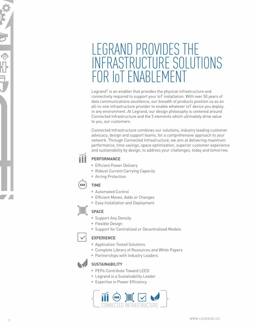
LEGRAND PROVIDES THE INFRASTRUCTURE SOLUTIONS FOR IoT ENABLEMENTLegrand® is an enabler that provides the physical infrastructure and connectivity required to support your IoT installation. With over 50 years of data communications excellence, our breadth of products position us as an all-in-one infrastructure provider to enable whatever IoT device you deploy, in any environment. At Legrand, our design philosophy is centered around Connected Infrastructure and the 5 elements which ultimately drive value to you, our customers.
Connected Infrastructure combines our solutions, industry leading customer advocacy, design and support teams, for a comprehensive approach to your network. Through Connected Infrastructure, we aim at delivering maximum performance, time savings, space optimization, superior customer experience and sustainability by design, to address your challenges, today and tomorrow.
PERFORMANCE■■ Efficient Power Delivery■■ Robust Current Carrying Capacity■■ Arcing Protection
TIME■■ Automated Control■■ Efficient Moves, Adds or Changes■■ Easy Installation and Deployment
SPACE■■ Support Any Density■■ Flexible Design■■ Support for Centralized or Decentralized Models
EXPERIENCE■■ Application Tested Solutions■■ Complete Library of Resources and White Papers■■ Partnerships with Industry Leaders
SUSTAINABILITY ■■ PEPs Contribute Toward LEED■■ Legrand is a Sustainability Leader ■■ Expertise in Power Efficiency
designed to be better.™
IoT APPLICATION GUIDE 9
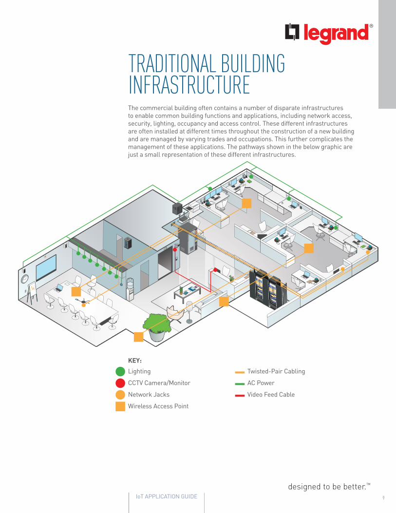
TRADITIONAL BUILDING INFRASTRUCTUREThe commercial building often contains a number of disparate infrastructures to enable common building functions and applications, including network access, security, lighting, occupancy and access control. These different infrastructures are often installed at different times throughout the construction of a new building and are managed by varying trades and occupations. This further complicates the management of these applications. The pathways shown in the below graphic are just a small representation of these different infrastructures.
KEY:
Lighting
CCTV Camera/Monitor
Network Jacks
Wireless Access Point
Twisted-Pair Cabling
AC Power
Video Feed Cable
WWW.LEGRAND.US10
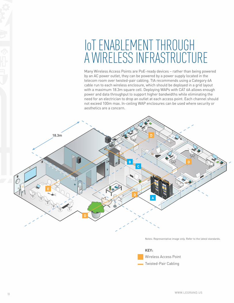
IoT ENABLEMENT THROUGH A WIRELESS INFRASTRUCTUREMany Wireless Access Points are PoE-ready devices – rather than being powered by an AC power outlet, they can be powered by a power supply located in the telecom room over twisted-pair cabling. TIA recommends using a Category 6A cable run to each wireless enclosure, which should be deployed in a grid layout with a maximum 18.3m square cell. Deploying WAPs with CAT 6A allows enough power and data throughput to support higher bandwidths while eliminating the need for an electrician to drop an outlet at each access point. Each channel should not exceed 100m max. In-ceiling WAP enclosures can be used where security or aesthetics are a concern.
Notes: Representative image only. Refer to the latest standards.
KEY:
Wireless Access Point
Twisted-Pair Cabling
A
CB
D
D
D
D
E
18.3m

designed to be better.™
IoT APPLICATION GUIDE 11
ENABLING INFRASTRUCTURE FOR WAP DEPLOYMENT (CENTRALIZED):
Telecommunications Room■■ Racks (see page 18)
■■ Cabinets (see page 19)
■■ Wire Mesh Cable Tray (see page 29)
■■ Patch Panels (see page 20)
■■ Copper Jacks (see page 20)
■■ Patch Cords (see page 21)
■■ Fiber Cable (see page 26)
■■ Fiber Connectivity (see page 24)
Pathways■■ Wire Mesh Cable Tray (see page 29)
■■ Tubular Runway (see page 29)
Cabling■■ Category 6A (see page 22)
WAP Connection Point■■ Plenum Rated Surface Mount Box (see page 21)
■■ Category 6A Patch Cord (see page 21)
ADDITIONAL OPTIONS:
Enclosures■■ WAP Enclosures (see page 28)
A
B
C
D
E
Mighty Mo® Racks
Tubular Runway
Surface Mount Box
Copper Cabling
WAP Enclosures
WWW.LEGRAND.US12
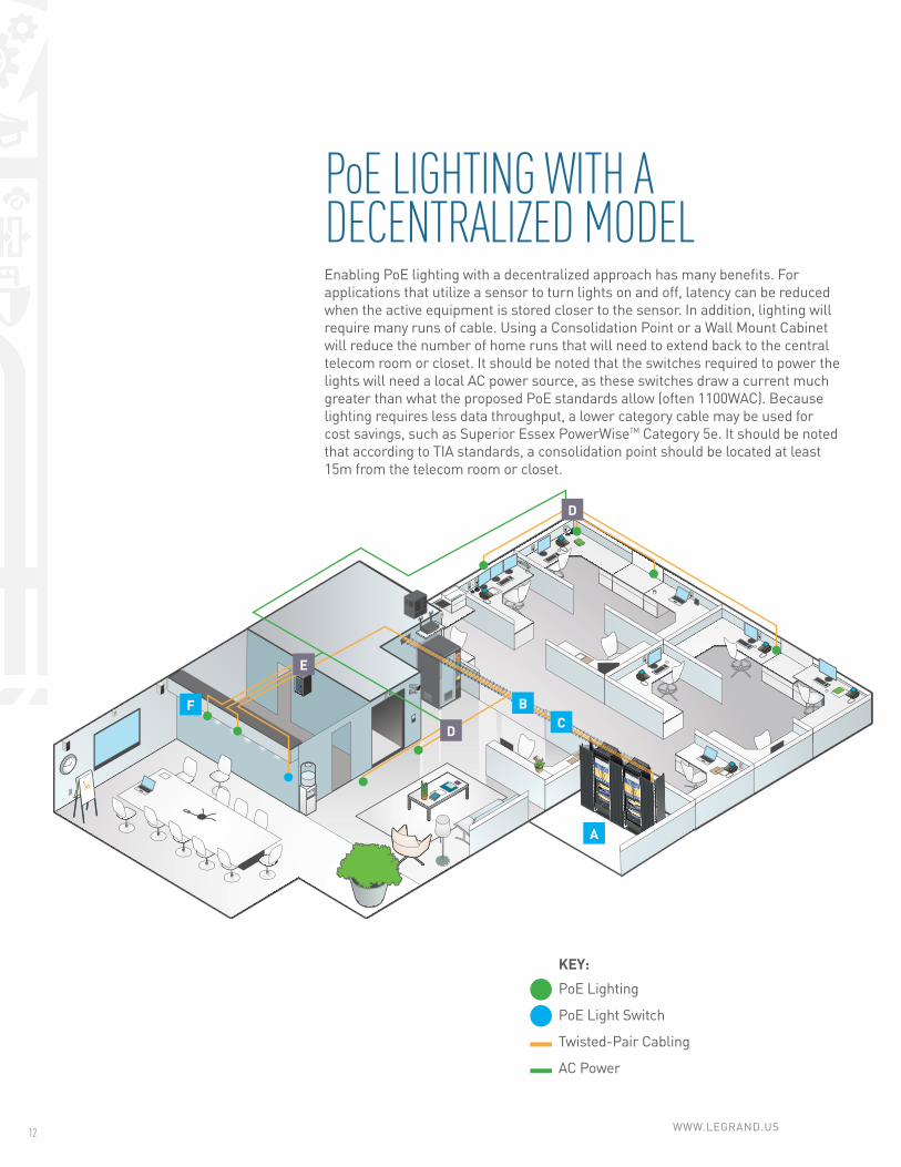
PoE LIGHTING WITH A DECENTRALIZED MODELEnabling PoE lighting with a decentralized approach has many benefits. For applications that utilize a sensor to turn lights on and off, latency can be reduced when the active equipment is stored closer to the sensor. In addition, lighting will require many runs of cable. Using a Consolidation Point or a Wall Mount Cabinet will reduce the number of home runs that will need to extend back to the central telecom room or closet. It should be noted that the switches required to power the lights will need a local AC power source, as these switches draw a current much greater than what the proposed PoE standards allow (often 1100WAC). Because lighting requires less data throughput, a lower category cable may be used for cost savings, such as Superior Essex PowerWiseTM Category 5e. It should be noted that according to TIA standards, a consolidation point should be located at least 15m from the telecom room or closet.
A
BFC
D
D
E
KEY:
PoE Lighting
PoE Light Switch
Twisted-Pair Cabling
AC Power

designed to be better.™
IoT APPLICATION GUIDE 13
ENABLING INFRASTRUCTURE FOR PoE LIGHTING DEPLOYMENT (DECENTRALIZED):
Telecommunications Room■■ Racks (see page 18)
■■ Cabinets (see page 19)
■■ Wire Mesh Cable Tray (see page 29)
■■ Patch Panels (see page 20)
■■ Copper Jacks (see page 20)
■■ Patch Cords (see page 21)
Pathways■■ Wire Mesh Cable Tray (see page 29)
■■ Tubular Runway (see page 29)
Cabling■■ Copper Cable (see page 22)
Consolidation Points■■ Enclosures (see page 28)
■■ Patch Panels (see page 20)
■■ Jacks (see page 20)
Wall Mount Cabinets
■■ Wall Mount Cabinets (see page 19)
■■ Patch Panels (see page 20)
■■ Jacks (see page 20)
Device Termination Point■■ Plenum Rated Surface Mount Box (see page 21)
■■ Patch Cords (see page 21)
A
B
C
D
E
F
Mighty Mo® Racks
Patch Panels
Wire Mesh Cable Tray
Patch Cords
Tubular Runway
Wall Mount Cabinets

WWW.LEGRAND.US14
PoE LIGHTING WITH A CENTRALIZED MODELAn IoT enabled infrastructure using a centralized approach allows a fully connected building while cutting back the need for AC power. With a centralized approach, it is recommended to follow the TIA standard star topology. Each channel should not exceed 100m, with 90m being a permanent link. It is recommended to take the color of your cables in to consideration, selecting different colors based on the application or device that they are supporting. This will allow for easier maintenance of your system. Also consider the ratio of power and data that a device will draw when selecting the right cabling for each application. A centralized approach requires a more robust telecommunications closet. It’s important to consider cooling implications, or even segregated racks dedicated to unique applications.
B
C
A
D
KEY:
PoE Lighting
PoE Light Switch
Twisted-Pair Cabling

designed to be better.™
IoT APPLICATION GUIDE 15
ENABLING INFRASTRUCTURE FOR PoE LIGHTING (CENTRALIZED):
Telecommunications Room■■ Racks (see page 18)
■■ Cabinets (see page 19)
■■ Wire Mesh Cable Tray (see page 29)
■■ Patch Panels (see page 20)
■■ Copper Jacks (see page 20)
■■ Patch Cords (see page 21)
Pathways■■ Wire Mesh Cable Tray (see page 29)
■■ Tubular Runway (see page 29)
Cabling■■ Copper Cable (see page 22)
Device Termination Point■■ Plenum Rated Surface Mount Box (see page 21)
■■ Patch Cords (see page 21)
A
B
C
D
Mighty Mo® Racks
GX Cabinets
Copper Jacks
Tubular Runway
Surface Mount Box
Copper Cabling

WWW.LEGRAND.US16
IoT APPLICATIONS WITH A HYBRID MODELA hybrid model allows for the benefits of both centralized and decentralized models to be realized within the building’s infrastructure. The centralized model will enable applications, such as wireless access in which the standards specifically call for centralization, to be deployed in the building environment. Meanwhile a decentralized model will coexist, allowing for the migration of processing closer to the source of the data where latency considerations are paramount. When delivering a decentralized model, secure wall-mount, free-standing cabinets or ceiling enclosures can be used at the edge with a just single network connection and AC power being provided to the enclosure. Networking, processing, storage, power and backup capabilities can be provided closer to the data source, distributing the load of the building across multiple zones.
A
BFC
D
D
E
G
KEY:
PoE Lighting
PoE Light Switch
CCTV Camera
Network Jacks
Wireless Access Point
Twisted-Pair Cabling
AC Power
H
H
H
H

designed to be better.™
IoT APPLICATION GUIDE 17
ENABLING INFRASTRUCTURE FOR IoT APPLICATIONS (HYBRID):
Telecommunications Room■■ Racks (see page 18)
■■ Cabinets (see page 19)
■■ Wire Mesh Cable Tray (see page 29)
■■ Patch Panels (see page 20)
■■ Copper Jacks (see page 20)
■■ Patch Cords (see page 21)
■■ Fiber Cable (see page 26)
■■ Fiber Connectivity (see page 24)
Pathways■■ Wire Mesh Cable Tray (see page 29)
■■ Tubular Runway (see page 29)
Cabling■■ Copper Cable (see page 22)
Consolidation Point■■ Enclosures (see page 28)
■■ Patch Panels (see page 20)
■■ Jacks (see page 20)
Wall Mount Cabinets■■ Patch Panels (see page 20)
■■ Jacks (see page 20)
■■ Wall Mount Cabinets (see page 19)
Device Termination Point■■ Plenum Rated Surface Mount Box (see page 21)
■■ Jacks (see page 20)
Workstation Outlets■■ Wall Plates (see page 21)
■■ Jacks (see page 20)
■■ Patch Cords (see page 21)
WAP Enclosures and Connection Points■■ Plenum Rated Surface Mount Box (see page 21)
■■ Category 6A Patch Cord (see page 21)
■■ WAP Enclosures (see page 28)
A
B
C
D
E
F
G
H
Mighty Mo® Racks
Q-Series Cabinets
Wall Plates
Wall Mount Cabinets
Patch Cords
Copper Jacks
WWW.LEGRAND.US18
MIGHTY MO 20 CHANNEL RACKS
PART NO. DESCRIPTION
OR-MM20716-X 16.25”D channel, 7’H, 45 RU, tapped #12-24
OR-MM20724-X 24”D channel, 7’H, 45 RU, tapped #12-24
OR-MM20730-X 30”D channel, 7’H, 45 RU, tapped #12-24
OR-MM20816-X 16.25”D channel, 8’H, 51 RU, tapped #12-24
OR-MM20824-X 24”D channel, 8’H, 51 RU, tapped #12-24
OR-MM20830-X 30”D channel, 8’H, 51 RU, tapped #12-24
MIGHTY MO 20 4-POST RACKS
OR-MM20736ADJ12-X 36”D adjustable, 7’H 45 RU, tapped #12-24
OR-MM20736ADJ38-X36”D adjustable, 7’H, 45 RU, punched 3/8” square
OR-MM20742ADJ12-X 42”D adjustable, 7’H, 45 RU, tapped #12-24
OR-MM20742ADJ38-X42”D adjustable, 7’H, 45 RU, punched 3/8” square
OR-MM20836ADJ12-X 36”D adjustable, 8’H, 51 RU, tapped #12-24
OR-MM20836ADJ38-X36”D adjustable, 8’H, 51 RU, punched 3/8” square
OR-MM20842ADJ12-X 42”D adjustable, 8’H, 51 RU, tapped #12-24
OR-MM20842ADJ38-X42”D adjustable, 8’H, 51 RU, punched 3/8” square
MIGHTY MO 20 4-POST FIXED RAILS
OR-MM20730FXD12-X 30”D fixed, 7’H, 45 RU, tapped #12-24
OR-MM20730FXD38-X 30”D fixed, 7’H, 45 RU, punched 3/8” square
OR-MM20830FXD12-X 30”D fixed, 8’H, 51 RU, tapped #12-24
OR-MM20830FXD38-X 30”D fixed, 8’ H, 51 RU, punched 3/8” square
MIGHTY MO 20 VERTICAL MANAGER WITH DOOR
OR-MM20VMD706-X 6.5”W x 10.25”D for 7’ MM20 racks
OR-MM20VMD710-X 10.5”W x 15”D for 7’ MM20 racks
OR-MM20VMD712-X 12.25”W x 15”D for 7’ MM20 racks
OR-MM20VMD806-X 6.5”W x 10.25”D for 8’ MM20 racks
OR-MM20VMD810-X 10.5”W x 15”D for 8’ MM20 racks
OR-MM20VMD812-X 12.25”W x 15”D for 8’ MM20 racks
Notes: Replace the“X” tail code with “B” for black or “W” for white.
MIGHTY MO 20 VERTICAL MANAGER WITH COVER
PART NO. DESCRIPTION
OR-MM20VMS704-X 3.75”W x 8.62”D for 7’ MM20 racks
OR-MM20VMS706-X 6”W x 8.62”D for 7’ MM20 racks
OR-MM20VMS710-X 10”W x 13.62”D for 7’ MM20 racks
OR-MM20VMS804-X 3.75”W x 8.62”D for 8’ MM20 racks
OR-MM20VMS806-X 6”W x 8.62”D for 8’ MM20 racks
OR-MM20VMS810-X 10”W x 13.62”D for 8’ MM20 racks
MIGHTY MO 20 VERTICAL MANAGER WITH COVER
OR-MM20VCT70206-X 2”W x 6”D for 7’ MM20 4-post racks
OR-MM20FCT70212-X 2”W x 12”D for 7’ MM20 4-post racks
OR-MM20VCT80206-X 2”W x 6”D for 8’ MM20 4-post racks
OR-MM20FCT80212-X 2”W x 12”D for 8’ MM20 4-post racks
Notes: Replace the“X” tail code with “B” for black or “W” for white.
STANDARD 2-POST RACK
OR-23-72-T2SD72”H x 24.19”W x 15.00”D, 38 RU, channel width: 3”, load rating: 750 lbs.
OR-19-84-T2SD84”H x 20.19”W x 15”D, 45 RU, channel width: 3”, load rating: 750 lbs.
OR-23-84-T2SD84”H x 24.19”W x 15”D, 45 RU, channel width: 3”, load rating: 750 lbs.
OR-19-72-T2SD72”H x 20.19”W x 15”D, 38 RU, channel width: 3”, load rating: 750 lbs.
STANDARD 4-POST RACK
OR-19-84-T4SDA152084”H x 20.19”W x 15”-20”D, 45 RU (1.75”), load rating: 1,000 lbs.
OR-19-84-T4SDA213284”H x 20.19”W x 21”-32”D, 45 RU (1.75”), load rating: 1,000 lbs.
OR-19-96-T4SDA213296”H x 20.19”W x 21”-32”D,51 RU (1.75”), load rating: 1,000 lbs.
STANDARD VERTICAL CABLE MANAGEMENT WITH CAGE COVER
OR-SVMS704 3.75”W x 6.58”D x 7’H
OR-SVMS706 6”W x 6.58”D x 7’H
OR-SVMS804 3.75”W x 6.58”D x 8’H
OR-SVMS806 6”W x 6.58”D x 8’H
OR-DVMS704 3.75”W x 13.17”D x 7’H
OR-DVMS706 6.00”W x 13.17”D x 7’H
OR-DVMS804 3.75”W x 13.17”D x 8’H
OR-DVMS806 6.00”W x 13.17”D x 8’H
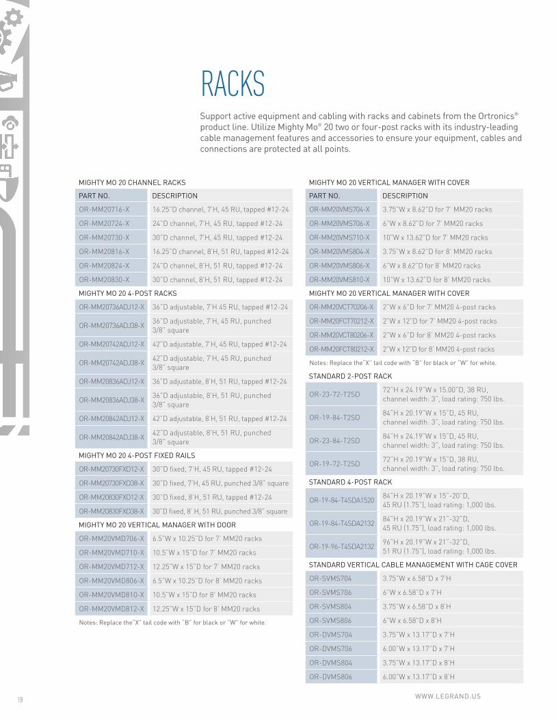
RACKSSupport active equipment and cabling with racks and cabinets from the Ortronics® product line. Utilize Mighty Mo® 20 two or four-post racks with its industry-leading cable management features and accessories to ensure your equipment, cables and connections are protected at all points.

designed to be better.™
IoT APPLICATION GUIDE 19
WALL MOUNT CABINETS
PART NO. DESCRIPTION
OR-MMW122426P-B 12U x 24”W x 26”D, Plexiglas® door, 23.50”H, 150 lbs. capacity, black
OR-MMW122420P-B 12U x 24”W x 20”D, Plexiglas® door, 23.50”H, 150 lbs. capacity, black
OR-MMW192420P-B 19U x 24”W x 20”D, Plexiglas® door, 35.75”H, 200 lbs. capacity, black
OR-MMW262420P-B 26U x 24”W x 20”D, Plexiglas® door, 48.00”H, 300 lbs. capacity, black
OR-MMW192426P-B 19U x 24”W x 26”D, Plexiglas® door, 35.75”H, 200 lbs. capacity, black
OR-MMW262426P-B 26U x 24”W x 26”D, Plexiglas® door, 48.00”H, 300 lbs. capacity, black
Q-SERIES CABINETS
OR-QC422442 Q-Series server cabinet, 42U x 600mmW x 1,000mmD, black
OR-QC422942 Q-Series network cabinet, 42U x 750mmW x 1,000mmD, black
GX CABINETS
OR-GXC422442-A1-B Server, cabinet assembly 42U (80.45”H), 24”W, 42”D, black
OR-GXC422942-A1-B Network, cabinet assembly 42U (80.45”H), 29.5”W, 42”D, black
CABINETSSupport a decentralized approach with wall-mount cabinets or secure critical IoT equipment in a free-standing cabinets from the Ortronics® product line.
Q-Series Cabinets GX Cabinets

WWW.LEGRAND.US20
COPPER JACKS
PART NO. DESCRIPTION
OR-HDJ5E Clarity HDJ Category 5e jack, 8 position, T568A/B, fog white
OR-HDJ6 Clarity HDJ Category 6 jack, 8 position, T568A/B, fog white
OR-HDJ6A Clarity HDJ Category 6a jack, 8 position, T568A/B, fog white
OR-KT2J5E Category 5e Keystone jack, lacing cap termination
OR-KT2J6 Category 6 Keystone jack, lacing cap termination
OR-KT2J6A Category 6A Keystone jack, lacing cap termination
Notes: For other colors add one of the following suffixes: -00 black, -36 blue, -42 red, -43 orange, -44 yellow, -45 green, -88 white, -13 ivory, -27 violet, -78 gray.
PATCH PANELS (LOADED)
24-PORT PART NO. 48-PORT PART NO. DESCRIPTION
OR-SP5EU24 OR-SP5EU48 Flat patch panel CAT 5e U/UTP
OR-SPA5EU24 OR-SPA5EU48 Angled patch panel CAT 5e U/UTP
OR-PHA5E6U24 OR-PHA5E6U48 Angled patch panel Clarity 5E
OR-PHD5E6U24 OR-PHD5E6U48 Flat patch panel Clarity 5E
OR-SP6U24 OR-SP6U48 Flat patch panel CAT 6 U/UTP
OR-SPA6U24 OR-SPA6U48 Angled patch panel CAT 6 U/UTP
OR-PHD610U24 OR-PHD610U48 Flat patch panel 610 Series CAT 6A U/UTP
OR-PHA610U24 OR-PHA610U48 Angled patch panel 610 Series CAT 6A U/UTP
OR-PHA66U24 OR-PHA66U48 Angled patch panel Clarity 6
OR-PHD66U24 OR-PHD66U48 Flat patch panel Clarity 6
OR-PHA6AU24 OR-PHA6AU48 Angled patch panel Clarity 6A/10G
OR-PHD6AU24 OR-PHD6AU48 Flat patch panel Clarity 6A/10G
PATCH PANELS (UNLOADED)
OR-SPKSU24 OR-SPKSU48 Flat panel kit unloaded for keystone
OR-SPAKSU24 OR-SPAKSU48 Angled panel kit unloaded for keystone
OR-SPKFU24 OR-SPKFU48 Flush load flat panel kit unloaded for keystone
OR-SPAKFU24 OR-SPAKFU48 Flush load angled panel kit unloaded for keystone
OR-PHAHJU24 OR-PHAHJU48 Angled HDJ panel unloaded
OR-PHDHJU24 OR-PHDHJU48 Flat HDJ panel unloaded
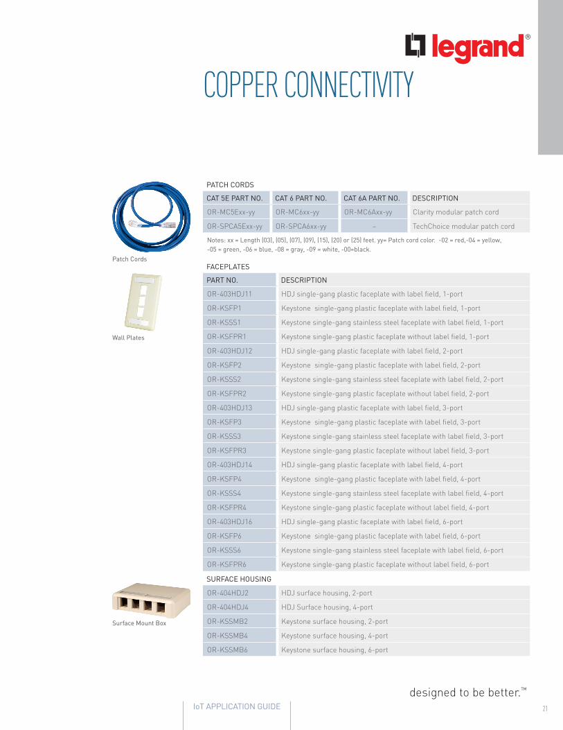
COPPER CONNECTIVITYLegrand’s copper connectivity enables PoE and other networked devices to connect with industry-leading performance at the workstation, in a ceiling enclosure, floor box, table box, rack or cabinet.
Copper Jacks
Patch Panels (Unloaded)
Patch Panels (Loaded)
designed to be better.™
IoT APPLICATION GUIDE 21
COPPER CONNECTIVITY
PATCH CORDS
CAT 5E PART NO. CAT 6 PART NO. CAT 6A PART NO. DESCRIPTION
OR-MC5Exx-yy OR-MC6xx-yy OR-MC6Axx-yy Clarity modular patch cord
OR-SPCA5Exx-yy OR-SPCA6xx-yy – TechChoice modular patch cord
Notes: xx = Length (03), (05), (07), (09), (15), (20) or (25) feet. yy= Patch cord color. -02 = red,-04 = yellow, -05 = green, -06 = blue, -08 = gray, -09 = white, -00=black.
FACEPLATES
PART NO. DESCRIPTION
OR-403HDJ11 HDJ single-gang plastic faceplate with label field, 1-port
OR-KSFP1 Keystone single-gang plastic faceplate with label field, 1-port
OR-KSSS1 Keystone single-gang stainless steel faceplate with label field, 1-port
OR-KSFPR1 Keystone single-gang plastic faceplate without label field, 1-port
OR-403HDJ12 HDJ single-gang plastic faceplate with label field, 2-port
OR-KSFP2 Keystone single-gang plastic faceplate with label field, 2-port
OR-KSSS2 Keystone single-gang stainless steel faceplate with label field, 2-port
OR-KSFPR2 Keystone single-gang plastic faceplate without label field, 2-port
OR-403HDJ13 HDJ single-gang plastic faceplate with label field, 3-port
OR-KSFP3 Keystone single-gang plastic faceplate with label field, 3-port
OR-KSSS3 Keystone single-gang stainless steel faceplate with label field, 3-port
OR-KSFPR3 Keystone single-gang plastic faceplate without label field, 3-port
OR-403HDJ14 HDJ single-gang plastic faceplate with label field, 4-port
OR-KSFP4 Keystone single-gang plastic faceplate with label field, 4-port
OR-KSSS4 Keystone single-gang stainless steel faceplate with label field, 4-port
OR-KSFPR4 Keystone single-gang plastic faceplate without label field, 4-port
OR-403HDJ16 HDJ single-gang plastic faceplate with label field, 6-port
OR-KSFP6 Keystone single-gang plastic faceplate with label field, 6-port
OR-KSSS6 Keystone single-gang stainless steel faceplate with label field, 6-port
OR-KSFPR6 Keystone single-gang plastic faceplate without label field, 6-port
SURFACE HOUSING
OR-404HDJ2 HDJ surface housing, 2-port
OR-404HDJ4 HDJ Surface housing, 4-port
OR-KSSMB2 Keystone surface housing, 2-port
OR-KSSMB4 Keystone surface housing, 4-port
OR-KSSMB6 Keystone surface housing, 6-port
Surface Mount Box
Wall Plates
Patch Cords

WWW.LEGRAND.US22
PREMISE COPPER
PRODUCT NAME LISTING PART NO. PACKAGING
10Gain® XP CAT 6ACMR 6H-272-xA
1,000' ReelCMP 6H-272-xB
10Gain CAT 6ACMR 6A-272-xA
1,000' ReelCMP 6A-272-xB
DataGain® CAT 6+
CMR66-246-xA 1,000' BrakeBox
66-240-xA 1,000' POP box
CMP66-246-xB 1,000' BrakeBox
66-240-xB 1,000' POP box
CAT 6
CMR77-246-xA 1,000 BrakeBox
77-240-xA 1,000' POP box
CMP77-2460xB 1,000' BrakeBox
77-240-xB 1,000' POP Box
PowerWise Category 5e
CMRPW52-H46-x5 1,000' BrakeBox
PW52-H72-x5 1,000' Plywood Reel
CMPPW52-H46-x8 1,000' BrakeBox
PW52-H72-x8 1,000' Plywood Reel
Cobra CAT 5e+
CMR52-200-x5 1,000' Reel-in-a-Box
52-240-x5 1,000' POP Box
CMP52-200-x8 1,000' Reel-in-a-Box
52-241-x8 1,000' POP Box
Notes: For other jacket colors replace”x” with one of the following suffixes: standard color 2=blue, 3=gray, 4=white, non-standard color 5=green, 6=yellow, 7=purple, 9=red, D=orange, E=black. Non-standard jacket colors and other packaging options (types and lengths) available with minimum order quantity and lead time.
COPPER CABLEThrough nCompassTM Systems, specified Legrand® connectivity and Superior Essex® cabling products can be combined to provide a limited lifetime warranty on a structured cabling system. Superior Essex copper cabling allows devices to be placed and connected in any number of locations with industry-leading performance. Superior Essex PowerWiseTM Category 5e cabling provides 88% power efficiency for PoE+ and future 4PPoE applications over 100 meter distances for current and future IoT deployments.

designed to be better.™
IoT APPLICATION GUIDE 23
FIBER CONNECTIVITYLegrand® fiber optic solutions from the Ortronics® product line support common, convenient approaches to fiber optic cabling. Support your building’s backbone with highly reliable, error-proof fiber cassettes and adapter panels to ensure the optimal performance of your network with the increased bandwidth being placed on it every day.
RACK MOUNT FIBER ENCLOSURES
PART NO. DESCRIPTION
OR-FC01U-P Rack-mount fiber enclosures, standard density, 1RU
OR-FC01U-C Rack-mount fiber patch and splice enclosures, 1RU
OR-FC02U-P Rack-mount fiber enclosures, standard density, 2RU
OR-FC02U-C Rack-mount fiber patch and splice enclosures, 2RU
OR-FC03U-P Rack-mount fiber enclosures, standard density, 3RU
OR-FC03U-C Rack-mount fiber patch and splice enclosures, 3RU
OR-FC04U-P Rack-mount fiber enclosures, standard density, 4RU
OR-FC04U-C Rack-mount fiber patch and splice enclosures, 4RU
ADAPTER PANELS
OR-OFP-MPA96LA Standard density adapter panel, (8) MPO, MM, aqua
OR-OFP-MPA72LA Standard density adapter panel, (6) MPO, MM, aqua
OR-OFP-LCQ24LC Standard density adapter panel, 6-LC quad, MM, aqua
OR-OFP-LCD12LC Standard density adapter panel, 6-LC duplex, MM, aqua
OR-OFP-SCD06LC Standard density adapter panel, 3-SC duplex, MM, aqua
OR-OFP-SCD08LC Standard density adapter panel, 4-SC duplex, MM, aqua
OR-OFP-SCD12LC Standard density adapter panel, 6-SC duplex, MM, aqua
OR-OFP-SCS06LC Standard density adapter panel, 6-SC simplex, MM, aqua
OR-OFP-MPA96MA Standard density adapter panel, (8) MPO, MM, beige
OR-OFP-MPA72MA Standard density adapter panel, (6) MPO, MM, beige
OR-OFP-LCQ24MB Standard density adapter panel, 6-LC quad, MM, beige
OR-OFP-LCD12MB Standard density adapter panel, 6-LC duplex, MM, beige
OR-OFP-SCD06MB Standard density adapter panel, 3-SC duplex, MM, beige
OR-OFP-SCD08MB Standard density adapter panel, 4-SC duplex, MM, beige
OR-OFP-SCD12MB Standard density adapter panel, 6-SC duplex, MM, beige
OR-OFP-SCS06MB Standard density adapter panel, 6-SC simplex, MM, beige
HIGH DENSITY FIBER MODULES FOR MIXED MEDIA PANELS
OR-HDFM-FLC2CL-00 High density fiber module, duplex LC, aqua
OR-HDFM-FSC1CL-00 High density fiber module, simplex SC, aqua
OR-HDFM-FLC2CA-00 High density fiber module, duplex LC, blue
OR-HDFM-FSC1CA-00 High density fiber module, simplex SC, blue
OR-HDFM-FLC2CC-00 High density fiber module, duplex LC, green
OR-HDFM-FSC1CC-00 High density fiber module, simplex SC, green
OR-HDFM-FLC2CM-00 High density fiber module, duplex LC, beige
OR-HDFM-FSC1CM-00 High density fiber module, simplex SC, beige
HIGH DENSITY FIBER MODULES FOR MIXED MEDIA PANELS (cont)
PART NO. DESCRIPTION
OR-HDFM-FLC2CG-00 High density fiber module, duplex LC, red
OR-HDFM-FSC1CG-00 High density fiber module, simplex SC, red
OR-HDFM-FLC2CI-00 High density fiber module, duplex LC, yellow
OR-HDFM-FSC1CI-00 High density fiber module, simplex SC, yellow
HIGH DENSITY FIBER MODULES FOR MIXED MEDIA PANELS, MPO
OR-HDFM-FMTZNL-00 High density fiber module, MPO, Type A, aqua
OR-HDFM-FMTZNC-00 High density fiber module, MPO, Type A, green
OR-HDFM-FMTZNM-00 High density fiber module, MPO, Type A, beige
OR-HDFM-FMTZNH-00 High density fiber module, MPO, Type A, black
OR-HDFM-FMTZNN-00 High density fiber module, MPO, Type A, magenta
OR-HDFM-FMTZNG-00 High density fiber module, MPO, Type A, red
OR-HDFM-FMTZNA-00 High density fiber module, MPO, Type A, blue
OR-HDFM-FMTZNE-00 High density fiber module, MPO, Type B, gray
MIXED MEDIA PATCH PANELS FOR HD FIBER MODULES
OR-PHAHJU24 High density panel, angled, 24-port, 1RU
OR-PHAHJU48 High density panel, angled, 48-port, 1RU
OR-PHAHJU72 High density panel, angled, 72-port, 2RU
OR-PHDHJU24 High density panel, flat, 24-port, 1RU
OR-PHDHJU48 High density panel, flat, 48-port, 1RU
OR-PHDHJU72 High density panel, flat, 72-port, 2RU
OR-HDCM-001 High density cable manager
FIBER CASSETTES
OR-M2LCQ24-50E3A1LC quad, 24-fiber, 50-micron LOMF,(2) MTP(M), premium performance, single-unit
OR-M2LCQ24-50ELC quad, 24-fiber, 50-micron LOMF,(2) MTP(M), high performance, single-unit
OR-M2LCD12-50ELC duplex, 12-fiber, 50-micron LOMF,(1) MTP(M), high performance, single-unit
OR-M2SCD12-50ESC duplex, 12-fiber, 50-micron LOMF,(1) MTP(M), high performance, single-unit
OR-HDCA6LC12AHHigh density cassette assembly, 50 LOMF (OM4+), 12-fiber, 1-MTP(M), 6-LC DX, 0.5dB max cassette insertion loss
Notes: MTP® is a registered trademark of US Conec, Ltd.

WWW.LEGRAND.US24
FIBER CONNECTORS
PART NO. DESCRIPTION
OR-205KNT9GA-50T Reusable connector, 50/125 LOMF, LC PC, aqua
OR-205KNT9FA-50T Reusable connector, 50/125 LOMF, SC PC, aqua
FIBER PATCH CORDS, DUPLEX
OR-P3DG8LPAZAZxxxMSpace Saver Premium Performance Laser Optimized (50/125), A-B, OM4, LC-PC, OFNP
OR-P3RG8LPAZAZxxxMSpace Saver Premium Performance Laser Optimized (50/125), A-A, OM4, LC-PC, OFNP
OR-P3DG8LPWZWZxxxMSpace Saver Premium Performance Laser Optimized (50/125), configurable, OM4, reconfigurable LC (RLC)-PC, OFNP
OR-P3DF8LPAZAZxxxMSpace Saver Premium Performance Laser Optimized (50/125), A-B, OM3, LC-PC, OFNP
OR-P3RF8LPAZAZxxxMSpace Saver Premium Performance Laser Optimized (50/125), A-A, OM3, LC-PC, OFNP
OR-P3DF8LPWZWZxxxMSpace Saver Premium Performance Laser Optimized (50/125), configurable, OM3, RLC-PC, OFNP
OR-P0DG8LPAZAZxxxMSpace Saver Standard Performance Laser Optimized (50/125), A-B, OM4, LC-PC, OFNP
OR-P0RG8LPAZAZxxxMSpace Saver Standard Performance Laser Optimized (50/125), A-A, OM4, LC-PC, OFNP
OR-P0DG8LPWZWZxxxMSpace Saver Standard Performance Laser Optimized (50/125), configurable, OM4, RLC-PC, OFNP
OR-P0DF8LPAZAZxxxMSpace Saver Standard Performance Laser Optimized (50/125), A-B, OM3, LC-PC, OFNP
OR-P0RF8LPAZAZxxxMSpace Saver Standard Performance Laser Optimized (50/125), A-A, OM3, LC-PC, OFNP
OR-P0DF8LPWZWZxxxMSpace Saver Standard Performance Laser Optimized (50/125), configurable, OM3, RLC-PC, OFNP
OR-P3DG2LRGZGZxxxM2mm Zip Cord Premium and High Performance Laser Optimized (50/125), configurable, OM4, LC-PC to LC-PC, OFNR
OR-P3DG2LRFZFZxxxM2mm Zip Cord Premium and High Performance Laser Optimized (50/125), configurable, OM4, SC-PC to SC-PC, OFNR
OR-P3DG2LRFZGZxxxM2mm Zip Cord Premium and High Performance Laser Optimized (50/125), configurable, OM4, SC-PC to LC-PC, OFNR
OR-P3DF2LRGZGZxxxM2mm Zip Cord Premium and High Performance Laser Optimized (50/125), configurable, OM3, LC-PC to LC-PC, OFNR
OR-P3DF2LRFZFZxxxM2mm Zip Cord Premium and High Performance Laser Optimized (50/125), configurable, OM3, SC-PC to SC-PC, OFNR
OR-P3DF2LRFZGZxxxM2mm Zip Cord Premium and High Performance Laser Optimized (50/125), configurable, OM3, SC-PC to LC-PC, OFNR
FIBER CONNECTIVITY
Fiber Connectors
Space Saver Fiber Patch Cords

designed to be better.™
IoT APPLICATION GUIDE 25
FIBER PATCH CORDS, DUPLEX (cont)
PART NO. DESCRIPTION
OR-P0DG2LRGZGZxxxMStandard Performance Laser Optimized (50/125), configurable, OM4, LC-PC to LC-PC, OFNR
OR-P0DG2LRFZFZxxxMStandard Performance Laser Optimized (50/125, configurable, OM4, SC-PC to SC-PC, OFNR)
OR-P0DG2LRFZGZxxxMStandard Performance Laser Optimized (50/125), configurable, OM4, SC-PC to LC-PC, OFNR
OR-P0DF2LRGZGZxxxM2mm Zip Cord Standard Performance Laser Optimized (50/125), configurable, OM3, LC-PC to LC-PC, OFNR
OR-P0DF2LRFZFZxxxM2mm Zip Cord Standard Performance Laser Optimized (50/125), configurable, OM3, SC-PC to SC-PC, OFNR
OR-P0DF2LRFZGZxxxM2mm Zip Cord Standard Performance Laser Optimized (50/125), configurable, OM3, SC-PC to LC-PC, OFNR
Notes: xxx = length in meters. Space Saver configurable patch cords ship A-B from factory.
FIBER CONNECTIVITY
Fiber Patch Cords
WWW.LEGRAND.US26
POWERWISE FIBER CABLE
PRODUCT NAME PART NO.FIBER COUNT
CONDUCTOR COUNT AWG (MM)
JACKET COLOR
NOMINAL DIAMETER PACKAGE
PowerWise Fiber Cable F3C3-002U15-6991-CE9 2 2 16 (1.47) Yellow 0.26 (6.6)Plywood
Reel
PREMISES FIBER (LOOSE TUBE)
PRODUCT NAME PART NO. LISTING CONFIGURATION FIBER COUNT PACKAGE
Microarray Data Center Interconnect
P3***xx01OFNR
3 mm Round 2 - 12
Reel
P3024xxA1 Duplex 24
V4***xx01
OFNP
2 mm Round 2 - 12
P4***xx01 3 mm Round 2 - 12
P4024xxC1 3.8 mm Round 24
P4024xxA1 Duplex 24
2 mm Microarray BreakoutV4***xxB1
OFNPMulti-unit 24, 36
V4***xx01 Multi-unit 48, 144
2 mm Interlock Armored, Microarray Breakout
L4***xVB1OFCP
Multi-unit 24, 36
L4***xV01 Multi-unit 48, 144
3 mm Microarray Breakout
P3024xxB1OFNR
Multi-unit 24
P3***xx01 Multi-unit 48 - 144
P4024xxB1OFNP
Multi-unit 24
P4***xx01 Multi-unit 48-144
3 mm Interlock Armored, Microarray Breakout
L3024xPB1OFCR
Multi-unit 24
L3***xP01 Multi-unit 48 - 144
L4024xPB1OFCP
Multi-unit 24
L4***xP01 Multi-unit 48 - 144
Notes: Where “***” = fiber count (i.e. 002, 004, 006, 008, 012, 018, 024, 036, 048, 060, 072, 096, 144) and “x” or “xx” = fiber type (refer to key).
KEY
MULTIMODE FIBER (MMF) TYPES
TeraFlex Bend Resistant Laser Optimized 50/125
10G/150 10G/300 10G/550
Replace “x” with: M N P
Replace “xx” with: MG NG PG
Premises Jacket Color Aqua
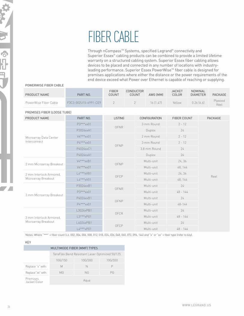
FIBER CABLEThrough nCompassTM Systems, specified Legrand® connectivity and Superior Essex® cabling products can be combined to provide a limited lifetime warranty on a structured cabling system. Superior Essex fiber cabling allows devices to be placed and connected in any number of locations with industry-leading performance. Superior Essex PowerWiseTM fiber cable is designed for premises applications where either the distance or the power requirements of the end device exceed what Power over Ethernet is capable of reaching or supplying.

designed to be better.™
IoT APPLICATION GUIDE 27
PREMISES FIBER (TIGHT BUFFER)
PRODUCT NAME PART NO. LISTING CONFIGURATION FIBER COUNT PACKAGE
Simplex, Duplex and Quad Interconnect
33***xx01
OFNR
3 mm Round 1 Reel
A3001x001 2 mm Round 1 Reel
B3002x001 3 mm Zip 2 Reel
C3002x001 2 mm Zip 2 Reel
33***xxyy 2 mm Zip 2 Refer to Key
34***xx01
OFNP
3 mm Round 1 Reel
A4001x01 2 mm Round 1 Reel
B4002x01 3 mm Zip 2 Reel
C4002xx01 2 mm Zip 2 Reel
34**xxyy Round 2, 4 Refer to Key
Single Unit Distribution
43***xxyyOFNR
Single Unit
6, 8, 12 Refer to Key
43***xK01 18, 24 Reel
44***xxyyOFNP
6, 8, 12 Refer to Key
44***xK01 18, 24 Reel
Rugged Indoor/Outdoor MDU D5001L5yy OFNR Round 1 Refer to Key
Indoor/Outdoor Sunlight Resistant
W4***xxyy
OFNPSingle Unit
2 - 12 Refer to Key
W5025xK01 24Reel
24***xx01 Multi-Unit 18 - 72
Single Unit,Interlock Armored,Tight Buffer
L3***x301
OFCR
Single Unit
2, 4
Reel
6, 8, 12L3***xK1Q
18, 24L3***x401
L4***x301
OFCP
2, 4
6, 8, 12L4***x401
18, 24L4***xK1Q
Notes: Where “***” = fiber count (i.e. 002, 004, 006, 008, 012, 018, 024, 036, 048, 060, 072, 096, 144) and “x” or “xx” = fiber type (refer to key).
KEY
MULTIMODE FIBER (MMF) TYPES
TeraGain62.5/125
TeraFlex Bend Resistant Laser Optimized 50/125
10G/150 10G/300 10G/550
Replace “x” with: 6 M N P
Replace “xx” with: 6G MG NG PG
Premises Jacket Color Orange Aqua
I/O Jacket Color Black
PACKAGING OPTIONS
Cut to LengthPlywood Reel
1,000 ftBrakeBox
Replace “yy” with:
1 BB
1,500 ftBrakeBox
2,000 ftBrakeBox
Replace “yy” with:
BD BC
WWW.LEGRAND.US28
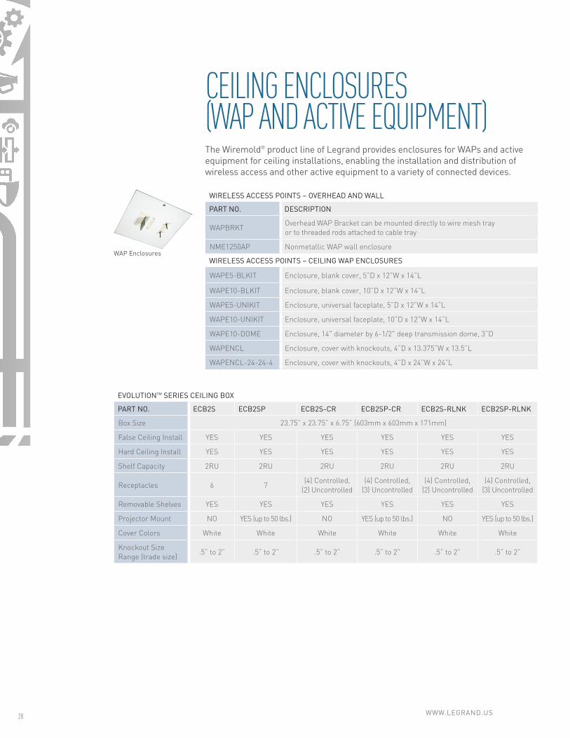
CEILING ENCLOSURES (WAP AND ACTIVE EQUIPMENT)The Wiremold® product line of Legrand provides enclosures for WAPs and active equipment for ceiling installations, enabling the installation and distribution of wireless access and other active equipment to a variety of connected devices.
WIRELESS ACCESS POINTS – OVERHEAD AND WALL
PART NO. DESCRIPTION
WAPBRKTOverhead WAP Bracket can be mounted directly to wire mesh tray or to threaded rods attached to cable tray
NME1250AP Nonmetallic WAP wall enclosure
WIRELESS ACCESS POINTS – CEILING WAP ENCLOSURES
WAPE5-BLKIT Enclosure, blank cover, 5”D x 12”W x 14”L
WAPE10-BLKIT Enclosure, blank cover, 10”D x 12”W x 14”L
WAPE5-UNIKIT Enclosure, universal faceplate, 5”D x 12”W x 14”L
WAPE10-UNIKIT Enclosure, universal faceplate, 10”D x 12”W x 14”L
WAPE10-DOME Enclosure, 14" diameter by 6-1/2" deep transmission dome, 3”D
WAPENCL Enclosure, cover with knockouts, 4”D x 13.375”W x 13.5”L
WAPENCL-24-24-4 Enclosure, cover with knockouts, 4”D x 24”W x 24”L
EVOLUTIONTM SERIES CEILING BOX
PART NO. ECB2S ECB2SP ECB2S-CR ECB2SP-CR ECB2S-RLNK ECB2SP-RLNK
Box Size 23.75” x 23.75” x 6.75” (603mm x 603mm x 171mm)
False Ceiling Install YES YES YES YES YES YES
Hard Ceiling Install YES YES YES YES YES YES
Shelf Capacity 2RU 2RU 2RU 2RU 2RU 2RU
Receptacles 6 7(4) Controlled,
(2) Uncontrolled (4) Controlled,
(3) Uncontrolled (4) Controlled,
(2) Uncontrolled (4) Controlled,
(3) Uncontrolled
Removable Shelves YES YES YES YES YES YES
Projector Mount NO YES (up to 50 lbs.) NO YES (up to 50 lbs.) NO YES (up to 50 lbs.)
Cover Colors White White White White White White
Knockout Size Range (trade size)
.5” to 2” .5” to 2” .5” to 2” .5” to 2” .5” to 2” .5” to 2”
WAP Enclosures

WIRE MESH CABLE TRAY
PART NO. DESCRIPTION
CF 30 1"D, widths from 2" to 12"
CF 54 2"D, widths from 2" to 24"
CF 105 4"D, widths from 4" to 24"
CF 150 6"D, widths from 6" to 24"
Notes: Multiple finish options are available. See catalog for complete product information.TUBULAR RUNWAY
OR-TR6-6B 6”W x 5’-11”L, load rating: 115 lbs.
OR-TR6-12B 12”W x 5’-11”L, load rating: 115 lbs.
OR-TR6-18B 18”W x 5’-11”L, load rating: 115 lbs.
OR-TR6-24B 24”W x 5’-11”L, load rating: 115 lbs.
OR-TR10-6B 6”W x 9’ 8.5”L, load rating: 115 lbs.
OR-TR10-12B 12 W x 9’-8.5”L, load rating: 115 lbs.
OR-TR10-18B 18”W x 9’-8.5”L, load rating: 115 lbs.
OR-TR10-24B 24”W x 9’-8.5”L, load rating: 115 lbs.
HORIZONTAL RADIUS RUNWAY
OR-TRHR12B 12”W x 18.03”IR x 29.66”OR*
OR-TRHR18B 18”W x 18.03”IR x 35.66”OR*
UNIVERSAL STYLE TUBULAR RUNWAY
OR-URT10-6B 6”W x 9’-11”L, black
OR-URT10-12B 12”W x 9’-11”L, black
OR-URT10-18B 18”W x 9’-11”L, black
OR-URT10-24B 24”W x 9’-11”L, black
TELCO STYLE TUBULAR RUNWAY
OR-TRT10-6B 6”W x 9’ 8.5”L, load rating: 115 lbs.
OR-TRT10-12B 12”W x 9’ 8.5”L, load rating: 115 lbs.
OR-TRT10-18B 18”W x 9’ 8.5”L, load rating: 115 lbs.
OR-TRT10-24B 24”W x 9’ 8.5”L, load rating: 115 lbs.
TELCO STYLE CURVED RUNWAY
OR-TRTC-6B 11.5”H x 6”W x 11.5”D
OR-TRTC-12B 11.5”H x 12”W x 11.5”D
OR-TRTC-18B 11.5”H x 18”W x 11.5”D
OR-TRTC-24B 11.5”H x 24”W x 11.5”D
OR-TRTCI-6B 11.5”H x 6”W x 11.5”D
OR-TRTCI-12B 11.5”H x 12”W x 11.5”D
OR-TRTCI-18B 11.5”H x 18”W x 11.5”D
OR-TRTCI-24B 11.5”H x 24”W x 11.5”D
Notes: *IR= inside radius; OR= outside radius. Replace “B” (black), with “D” for dove gray.
designed to be better.™
IoT APPLICATION GUIDE 29
PATHWAYSLegrand’s cable pathways allows for efficient routing of data communications cable in any building environment. Find the right solution for your installation with a variety of options from industry-leading wire-mesh cable tray with the Cablofil® product line to tubular runway from the Ortronics® product line.
Tubular Runway
Wire Mesh Cable Tray

designed to be better.™
©20
16
Leg
rand
A
ll R
ight
s R
eser
ved
re
v. 0
6|16
IO
T_A
PP
GU
IDE
Data Communications
125 Eugene O’Neill DriveNew London, CT 06320800.934.5432www.legrand.us
570 Applewood CrescentVaughan, Ontario L4K 4B4905.738.9195 www.legrand.ca
Follow Us