Embed Size (px)
DESCRIPTION
Internet Networking Spring 2003. Tutorial 11 Explicit Congestion Notification (RFC 3168). Network Congestion. - PowerPoint PPT Presentation
Citation preview
1
Internet Networking Spring 2003
Tutorial 11 Explicit Congestion Notification
(RFC 3168)

2
Network Congestion
• The network's state of congestion is determined by end-systems probing for
the network state, by gradually increasing the load on the network
(by increasing the window of packets that are outstanding in the network)
until the network becomes congested and a packet is lost.
• TCP's congestion management algorithms have techniques built-in (such as
Fast Retransmit and Fast Recovery) to minimize the impact of losses, from
a throughput perspective.
• Treating loss as an indication of congestion in the network is appropriate for
data with little or no sensitivity to individual packet loss.
• There are many applications sensitive to the delay or loss of one or more
individual packets (e.g., realtime traffic).
3
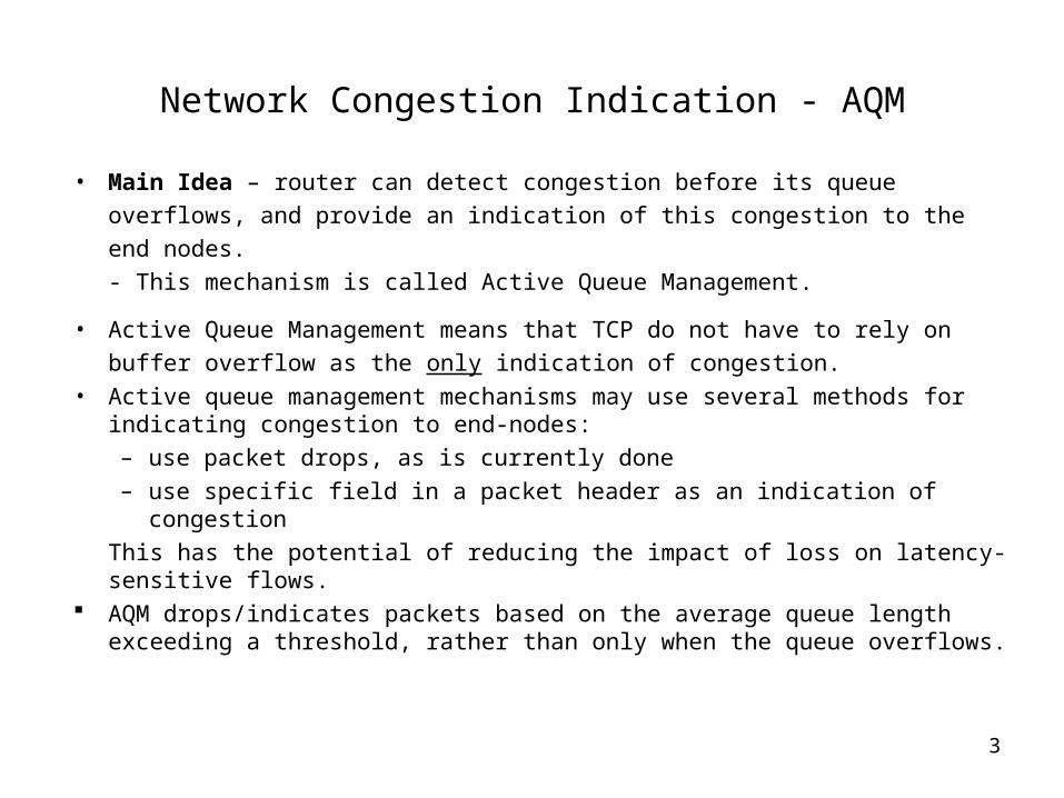
Network Congestion Indication - AQM
• Main Idea – router can detect congestion before its queue overflows, and
provide an indication of this congestion to the end nodes.
- This mechanism is called Active Queue Management.
• Active Queue Management means that TCP do not have to rely on buffer
overflow as the only indication of congestion.
• Active queue management mechanisms may use several methods for indicating congestion to end-nodes:
– use packet drops, as is currently done
– use specific field in a packet header as an indication of congestion
This has the potential of reducing the impact of loss on latency-sensitive flows.
AQM drops/indicates packets based on the average queue length exceeding a threshold, rather than only when the queue overflows.

4
General Principles
• Co-existence - cooperation with existing TCP mechanisms for adapting to
congestion and with routers' current practice of dropping packets in periods
of congestion.
• Congestion persistence - the time scales that we are concerned with are
congestion events that may last longer than a round-trip time.
• Long-time flow - we are interested in managing the congestion caused by
flows that send enough packets so that they are still active when network
feedback reaches them.
• Asymmetric routing - the path followed by data packets may be different
from the path followed by the acknowledgment packets in the reverse
direction.
5
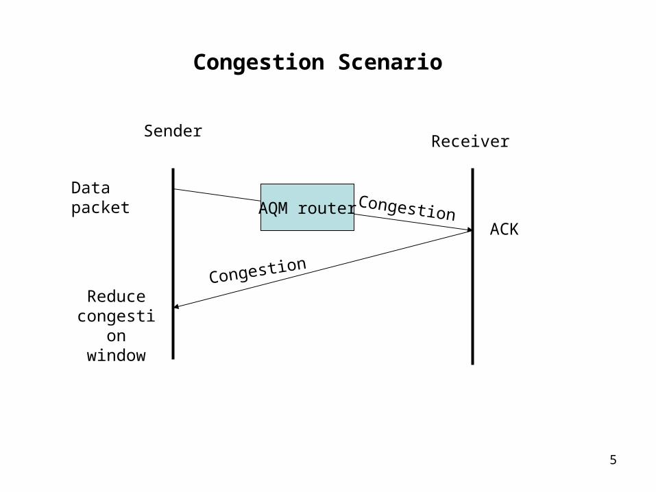
Congestion Scenario
AQM router
SenderReceiver
Congestion
Congestion
Data packet
ACK
Reduce congestion
window
6
Congestion Notification in IP
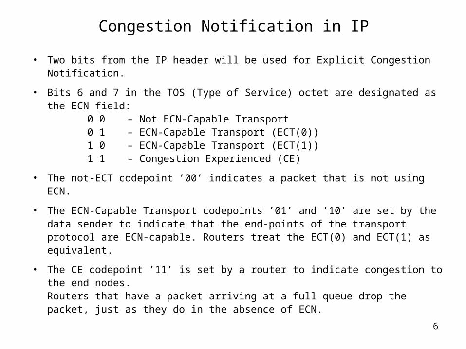
• Two bits from the IP header will be used for Explicit Congestion Notification.
• Bits 6 and 7 in the TOS (Type of Service) octet are designated as the ECN field:
0 0 – Not ECN-Capable Transport0 1 – ECN-Capable Transport (ECT(0))1 0 – ECN-Capable Transport (ECT(1))1 1 – Congestion Experienced (CE)
• The not-ECT codepoint ’00’ indicates a packet that is not using ECN.
• The ECN-Capable Transport codepoints ’01’ and ’10’ are set by the data sender to indicate that the end-points of the transport protocol are ECN-capable. Routers treat the ECT(0) and ECT(1) as equivalent.
• The CE codepoint ’11’ is set by a router to indicate congestion to the end nodes.Routers that have a packet arriving at a full queue drop the packet, just as they do in the absence of ECN.

7
Congestion Notification in IP (end nodes)
• Upon the receipt by an ECN-Capable transport of a single CE packet, the
congestion control algorithm must be essentially the same as the
congestion control response to a single dropped packet. E.g., ECN-capable
TCP source halve its congestion window for either a packet drop or an ECN
indication.
• The reason for requiring the same congestion-control response is to
accommodate the incremental deployment of ECN in both end-systems and
in routers. If there were different congestion control responses to a CE
codepoint than to a packet drop, this could result in unfair treatment for
different flows.
• An additional goal is that the end-systems should react to congestion at
most once per window of data (i.e., at most once per round-trip time), to
avoid reacting multiple times to multiple indications of congestion within a
round-trip time.

8
Congestion Notification in IP (routers)
• Router should set the CE codepoint of an ECN-Capable packet only if it would otherwise drop the packet as an indication of congestion to the end nodes.
• When a CE packet (i.e., a packet that has the CE codepoint set) is received by a router, the CE codepoint is left unchanged, and the packet is transmitted as usual.
• An environment where all end nodes were ECN-Capable could allow new
criteria to be developed for setting the CE codepoint, and new congestion
control mechanisms for end-node reaction to CE packets.
• Additional treatment should be done for fragmentated and encapsulated
packets.

9
AQM router behavior
ECT(0)
Congested router Not congested router
CE
CE CE
ECT(0) ECT(0)
CE CE
May also drop the packet
not-ECT not-ECT not-ECTDrops the packet

10
Congestion Notification in TCP
• For TCP, ECN requires three new pieces of functionality:
– negotiation between the endpoints during connection setup to determine
if they are both ECN-capable
– ECN-Echo flag in the TCP header so that the data receiver can inform
the data sender when a CE packet has been received
– Congestion Window Reduced flag in the TCP header so that the data
sender can inform the data receiver that the congestion window has
been reduced
• Two last bits of the Reserved field in the TCP header are designated as
ECN-Echo (ECE) and Congestion Window Reduced (CWR) flags.
• Thus, ECN uses the ECT and CE flags in the IP header for signaling
between routers and connection endpoints, and uses the ECN-Echo and
CWR flags in the TCP header for TCP-endpoint to TCP-endpoint signaling.

11
Congestion Notification in TCP (cont.)
For a TCP connection, a typical sequence of events in an ECN-based reaction
to congestion is as follows:
• An ECT codepoint is set in packets transmitted by the sender to indicate that
ECN is supported by the transport entities for these packets.
• An ECN-capable router detects impending congestion and detects that an
ECT codepoint is set in the packet it is about to drop. Instead of dropping the
packet, the router chooses to set the CE codepoint in the IP header and
forwards the packet.
• The receiver receives the packet with the CE codepoint set, and sets the
ECN-Echo flag in its next TCP ACK sent to the sender.
• The sender receives the TCP ACK with ECN-Echo set, and reacts to the
congestion as if a packet had been dropped (sstresh=cwnd=old_cwnd/2).
• The sender sets the CWR flag in the TCP header of the next packet sent to
the receiver to acknowledge its receipt of and reaction to the ECN-Echo flag.

12
TCP Initialization
• In the TCP connection setup phase, the source and destination TCPs
exchange information about their willingness to use ECN.
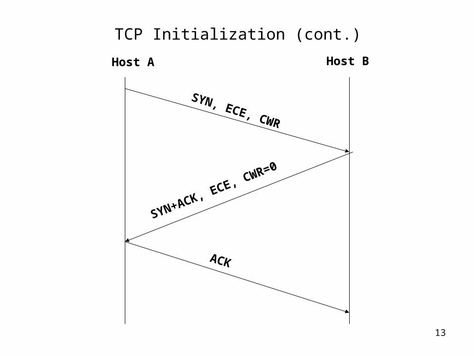
• Before a TCP connection can use ECN, Host A sends an ECN-setup SYN
packet (ECE and CWR are set), and Host B sends an ECN-setup SYN-ACK
(ECE set, CWR unset) packet.
– This asymmetry is necessary for the robust negotiation of ECN-capability with
some deployed TCP implementations which simply copy the Reserved field from
the received data packet to the ACK packet.
• Subsequent to the completion of this negotiation, the TCP sender sets an
ECT codepoint in the IP header of data packets to indicate to the network
that the transport is capable and willing to participate in ECN for this packet.
– This indicates to the routers that they may mark this packet with the CE
codepoint, if they would like to use that as a method of congestion notification.
13
TCP Initialization (cont.)
SYN, ECE, CWR
SYN+ACK, ECE, CWR=0
Host A Host B
ACK

14
TCP Sender
• For a TCP connection using ECN, new data packets are transmitted with an
ECT codepoint set in the IP header. If the sender receives an ACK packet
with the ECN-Echo flag set in the TCP header, then the sender knows that
congestion was encountered in the network on the path from the sender to
the receiver.
• The indication of congestion should be treated just as a congestion loss in
non-ECN-Capable TCP. That is, the TCP source halves the congestion
window "cwnd" and reduces the slow start threshold "sstresh".
• TCP should not react to congestion indications more than once every
window of data.
• When an ECN-Capable TCP sender reduces its congestion window for any
reason (because of a retransmit timeout, a Fast Retransmit, or in response
to an ECN Notification), the TCP sender sets the CWR flag in the TCP
header of the first new data packet sent after the window reduction.
15
TCP Receiver
• When TCP receives a CE data packet at the destination end-system, the
TCP data receiver sets the ECN-Echo flag in the TCP header of the
subsequent ACK packet.
• To provide robustness against the possibility of a dropped ACK packet
carrying an ECN-Echo flag, the TCP receiver sets the ECN-Echo flag in a
series of ACK packets sent subsequently (whether they acknowledge CE
data packets or non-CE data packets).
• The TCP receiver uses the CWR flag received from the TCP sender to
determine when to stop setting the ECN-Echo flag.

16
SenderReceiver
Data packets
ACKs with ECN-Echo
flag set
Router
IP: ECT(0)
IP: ECT(0)
IP: ECT(0)
IP: CE
IP: CE
IP: ECT(0)IP: not-ECTIP: not-ECT
TCP: ECN-Echo
TCP: ECN-Echo
TCP: ECN-Echo
TCP: ECN-Echo
Congestion
Reduce congestion
window
TCP: CWR
cwnd doesn’t
reduced
Stop set ECN-Echo flag
TCP: ECN-Echo=0

17
TCP/IP changes summary
• IP changes:
– Two bits in the IP header to be used for ECN.
– The not-ECT codepoint indicates that the transport protocol will ignore the CE codepoint. This is the default value for the ECN codepoint.
– The ECT codepoints indicate that the transport protocol is willing and able to participate in ECN.
– The router sets the CE codepoint to indicate congestion to the end nodes. The CE codepoint in a packet header must not be reset by a router.
• TCP changes:
– Two bits in the TCP header.
– Setup phase.
– The ECN-Echo flag is used by the data receiver to inform the data sender of a received CE packet.
– The Congestion Window Reduced (CWR) flag is used by the data sender to inform the data receiver that the congestion window has been reduced.