Embed Size (px)
Citation preview

Internet Engineering Task Force G.Galimberti, Ed.Internet-Draft CiscoIntended status: Standards Track R.Kunze, Ed.Expires: January 7, 2016 Deutsche Telekom K. Lam, Ed. Alcatel-Lucent D. Hiremagalur, Ed. G. G.Grammel, Ed. Juniper L.Fang, Ed. G.Ratterree, Ed. Microsoft July 6, 2015
A YANG model to manage the optical interface parameters of "G.698.2 single channel" in DWDM applications draft-dharini-netmod-g-698-2-yang-04
Abstract
This memo defines a Yang model that translates the SNMP mib module defined in draft-galikunze-ccamp-g-698-2-snmp-mib for managing single channel optical interface parameters of DWDM applications, using the approach specified in G.698.2. This model is to support the optical parameters specified in ITU-T G.698.2 [ITU.G698.2] and application identifiers specified in ITU-T G.874.1 [ITU.G874.1] . Note that G.874.1 encompasses vendor-specific codes, which if used would make the interface a single vendor IaDI and could still be managed.
The Yang model defined in this memo can be used for Optical Parameters monitoring and/or configuration of the endpoints of the multi-vendor IaDI based on the Black Link approach.
Copyright Notice
Copyright (c) 2014 IETF Trust and the persons identified as the document authors. All rights reserved.
Status of This Memo
This Internet-Draft is submitted in full conformance with the provisions of BCP 78 and BCP 79.
Internet-Drafts are working documents of the Internet Engineering Task Force (IETF). Note that other groups may also distribute working documents as Internet-Drafts. The list of current Internet- Drafts is at http://datatracker.ietf.org/drafts/current/.
G.Galimberti, et al. Expires January 7, 2016 [Page 1]

Internet-Draft draft-dharini-netmod-g-698-2-yang-04 July 2015
Internet-Drafts are draft documents valid for a maximum of six months and may be updated, replaced, or obsoleted by other documents at any time. It is inappropriate to use Internet-Drafts as reference material or to cite them other than as "work in progress."
This Internet-Draft will expire on January 7, 2016.
Copyright Notice
Copyright (c) 2015 IETF Trust and the persons identified as the document authors. All rights reserved.
This document is subject to BCP 78 and the IETF Trust’s Legal Provisions Relating to IETF Documents (http://trustee.ietf.org/license-info) in effect on the date of publication of this document. Please review these documents carefully, as they describe your rights and restrictions with respect to this document. Code Components extracted from this document must include Simplified BSD License text as described in Section 4.e of the Trust Legal Provisions and are provided without warranty as described in the Simplified BSD License.
Table of Contents
1. Introduction . . . . . . . . . . . . . . . . . . . . . . . . 3 2. The Internet-Standard Management Framework . . . . . . . . . 4 3. Conventions . . . . . . . . . . . . . . . . . . . . . . . . . 4 4. Overview . . . . . . . . . . . . . . . . . . . . . . . . . . 4 4.1. Optical Parameters Description . . . . . . . . . . . . . 5 4.1.1. Rs-Ss Configuration . . . . . . . . . . . . . . . . . 6 4.1.2. Table of Application Codes . . . . . . . . . . . . . 7 4.2. Use Cases . . . . . . . . . . . . . . . . . . . . . . . . 7 4.3. Optical Interface for G.698.2 . . . . . . . . . . . . . . 14 5. Structure of the Yang Module . . . . . . . . . . . . . . . . 14 6. Yang Module . . . . . . . . . . . . . . . . . . . . . . . . . 15 7. Security Considerations . . . . . . . . . . . . . . . . . . . 19 8. IANA Considerations . . . . . . . . . . . . . . . . . . . . . 20 9. Acknowledgements . . . . . . . . . . . . . . . . . . . . . . 20 10. Contributors . . . . . . . . . . . . . . . . . . . . . . . . 20 11. References . . . . . . . . . . . . . . . . . . . . . . . . . 21 11.1. Normative References . . . . . . . . . . . . . . . . . . 21 11.2. Informative References . . . . . . . . . . . . . . . . . 23 Appendix A. Change Log . . . . . . . . . . . . . . . . . . . . . 24 Appendix B. Open Issues . . . . . . . . . . . . . . . . . . . . 24 Authors’ Addresses . . . . . . . . . . . . . . . . . . . . . . . 24
G.Galimberti, et al. Expires January 7, 2016 [Page 2]

Internet-Draft draft-dharini-netmod-g-698-2-yang-04 July 2015
1. Introduction
This memo defines a Yang model that translates the SNMP mib module defined in draft-galikunze-ccamp-g-698-2-snmp-mib for managing single channel optical interface parameters of DWDM applications, using the approach specified in G.698.2. This model is to support the optical parameters specified in ITU-T G.698.2 [ITU.G698.2], application identifiers specified in ITU-T G.874.1 [ITU.G874.1] and the Optical Power at Transmitter and Receiver side. Note that G.874.1 encompasses vendor-specific codes, which if used would make the interface a single vendor IaDI and could still be managed.‘
The Black Link approach allows supporting an optical transmitter/ receiver pair of one vendor to inject an optical tributary signal and run it over an optical network composed of amplifiers, filters, add- drop multiplexers from a different vendor. In the OTN architecture, the ’black-link’ represents a pre-certified network media channel conforming to G.698.2 specifications at the S and R reference points.
[Editor’s note: In G.698.2 this corresponds to the optical path from point S to R; network media channel is also used and explained in draft-ietf-ccamp-flexi-grid-fwk-02]
Management will be performed at the edges of the network media channel (i.e., at the transmitters and receivers attached to the S and R reference points respectively) for the relevant parameters specified in G.698.2 [ITU.G698.2], G.798 [ITU.G798], G.874 [ITU.G874], and the performance parameters specified in G.7710/Y.1701 [ITU-T G.7710] and G.874.1 [ITU.G874.1].
G.698.2 [ITU.G698.2] is primarily intended for metro applications that include optical amplifiers. Applications are defined in G.698.2 [ITU.G698.2] using optical interface parameters at the single-channel connection points between optical transmitters and the optical multiplexer, as well as between optical receivers and the optical demultiplexer in the DWDM system. This Recommendation uses a methodology which does not explicitly specify the details of the optical network between reference point Ss and Rs, e.g., the passive and active elements or details of the design. The Recommendation currently includes unidirectional DWDM applications at 2.5 and 10 Gbit/s (with 100 GHz and 50 GHz channel frequency spacing). Work is still under way for 40 and 100 Gbit/s interfaces. There is possibility for extensions to a lower channel frequency spacing. This document specifically refers to the "application code" defined in the G.698.2 [ITU.G698.2] and included in the Application Identifier defined in G.874.1 [ITU.G874.1] and G.872 [ITU.G872], plus a few optical parameters not included in the G.698.2 application code specification.
G.Galimberti, et al. Expires January 7, 2016 [Page 3]
Internet-Draft draft-dharini-netmod-g-698-2-yang-04 July 2015
This draft refers and supports the draft-kunze-g-698-2-management- control-framework
The building of a yang model describing the optical parameters defined in G.698.2 [ITU.G698.2], and reflected in G.874.1 [ITU.G874.1], allows the different vendors and operator to retrieve, provision and exchange information across the G.698.2 multi-vendor IaDI in a standardized way. In addition to the parameters specified in ITU recommendations the Yang models support also the "vendor specifica application identifier", the Tx and Rx power at the Ss and Rs points and the channel frequency.
The Yang Model, reporting the Optical parameters and their values, characterizes the features and the performances of the optical components and allow a reliable black link design in case of multi vendor optical networks.
Although RFC 3591 [RFC3591], which draft-galikunze-ccamp-g-698-2- snmp-mib is extending, describes and defines the SNMP MIB of a number of key optical parameters, alarms and Performance Monitoring, as this RFC is over a decade old, it is primarily pre-OTN, and a more complete and up-to-date description of optical parameters and processes can be found in the relevant ITU-T Recommendations. The same considerations can be applied to the RFC 4054 [RFC4054].
2. The Internet-Standard Management Framework
For a detailed overview of the documents that describe the current Internet-Standard Management Framework, please refer to section 7 of RFC 3410 [RFC3410].
This memo specifies a Yang model for optical interfaces.
3. Conventions
The key words "MUST", "MUST NOT", "REQUIRED", "SHALL", "SHALL NOT", "SHOULD", "SHOULD NOT", "RECOMMENDED", "MAY", and "OPTIONAL" in this document are to be interpreted as described in RFC 2119 [RFC2119] In the description of OIDs the convention: Set (S) Get (G) and Trap (T) conventions will describe the action allowed by the parameter.
4. Overview
G.Galimberti, et al. Expires January 7, 2016 [Page 4]
Internet-Draft draft-dharini-netmod-g-698-2-yang-04 July 2015
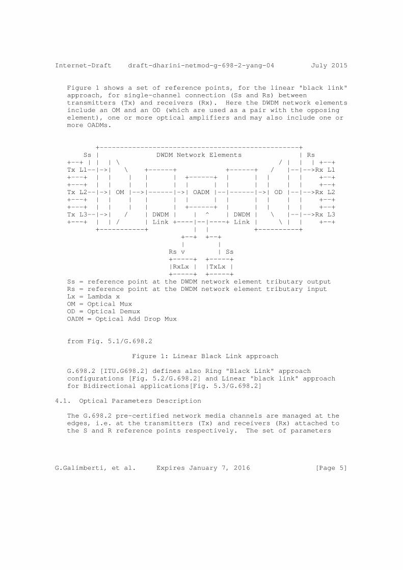
Figure 1 shows a set of reference points, for the linear "black link" approach, for single-channel connection (Ss and Rs) between transmitters (Tx) and receivers (Rx). Here the DWDM network elements include an OM and an OD (which are used as a pair with the opposing element), one or more optical amplifiers and may also include one or more OADMs.
+-------------------------------------------------+ Ss | DWDM Network Elements | Rs +--+ | | | \ / | | | +--+ Tx L1--|->| \ +------+ +------+ / |--|-->Rx L1 +---+ | | | | | +------+ | | | | | +--+ +---+ | | | | | | | | | | | | +--+ Tx L2--|->| OM |-->|------|->| OADM |--|------|->| OD |--|-->Rx L2 +---+ | | | | | | | | | | | | +--+ +---+ | | | | | +------+ | | | | | +--+ Tx L3--|->| / | DWDM | | ^ | DWDM | \ |--|-->Rx L3 +---+ | | / | Link +----|--|----+ Link | \ | | +--+ +-----------+ | | +----------+ +--+ +--+ | | Rs v | Ss +-----+ +-----+ |RxLx | |TxLx | +-----+ +-----+ Ss = reference point at the DWDM network element tributary output Rs = reference point at the DWDM network element tributary input Lx = Lambda x OM = Optical Mux OD = Optical Demux OADM = Optical Add Drop Mux
from Fig. 5.1/G.698.2
Figure 1: Linear Black Link approach
G.698.2 [ITU.G698.2] defines also Ring "Black Link" approach configurations [Fig. 5.2/G.698.2] and Linear "black link" approach for Bidirectional applications[Fig. 5.3/G.698.2]
4.1. Optical Parameters Description
The G.698.2 pre-certified network media channels are managed at the edges, i.e. at the transmitters (Tx) and receivers (Rx) attached to the S and R reference points respectively. The set of parameters
G.Galimberti, et al. Expires January 7, 2016 [Page 5]

Internet-Draft draft-dharini-netmod-g-698-2-yang-04 July 2015
that could be managed are specified in G.698.2 [ITU.G698.2] section 5.3 referring the "application code" notation
The definitions of the optical parameters are provided below to increase the readability of the document, where the definition is ended by (R) the parameter can be retrieve with a read, when (W) it can be provisioned by a write, (R,W) can be either read or written.
4.1.1. Rs-Ss Configuration
The Rs-Ss configuration table allows configuration of Central Frequency, Power and Application codes as described in [ITU.G698.2] and G.694.1 [ITU.G694.1] This parameter report the current Transceiver Output power, it can be either a setting and measured value (G, S).
Central frequency (see G.694.1 Table 1) (see G.694.1 Table 1): This parameter indicates the Central frequency value that Ss and Rs will be set to work (in THz). See the details in Section 6/ G.694.1 (G, S).
Single-channel application codes(see G.698.2): This parameter indicates the transceiver application code at Ss and Rs as defined in [ITU.G698.2] Chapter 5.4 - this parameter can be called Optical Interface Identifier OII as per [draft- martinelli-wson-interface-class](G).
Number of Single-channel application codes Supported This parameter indicates the number of Single-channel application codes supported by this interface (G).
Current Laser Output power: This parameter report the current Transceiver Output power, it can be either a setting and measured value (G, S).
Current Laser Input power: This parameter report the current Transceiver Input power (G).
G.Galimberti, et al. Expires January 7, 2016 [Page 6]
Internet-Draft draft-dharini-netmod-g-698-2-yang-04 July 2015
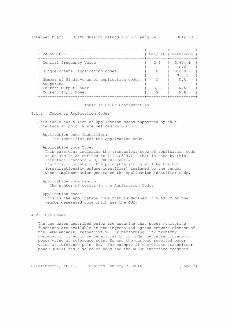
+---------------------------------------------+---------+-----------+ | PARAMETERS | Get/Set | Reference | +---------------------------------------------+---------+-----------+ | Central frequency Value | G,S | G.694.1 | | | | S.6 | | Single-channel application codes | G | G.698.2 | | | | S.5.3 | | Number of Single-channel application codes | G | N.A. | | Supported | | | | Current Output Power | G,S | N.A. | | Current Input Power | G | N.A. | +---------------------------------------------+---------+-----------+
Table 1: Rs-Ss Configuration
4.1.2. Table of Application Codes
This table has a list of Application codes supported by this interface at point R are defined in G.698.2.
Application code Identifier: The Identifier for the Application code.
Application code Type: This parameter indicates the transceiver type of application code at Ss and Rs as defined in [ITU.G874.1], that is used by this interface Standard = 0, PROPRIETARY = 1 The first 6 octets of the printable string will be the OUI (organizationally unique identifier) assigned to the vendor whose implementation generated the Application Identifier Code.
Application code Length: The number of octets in the Application Code.
Application code: This is the application code that is defined in G.698.2 or the vendor generated code which has the OUI.
4.2. Use Cases
The use cases described below are assuming that power monitoring functions are available in the ingress and egress network element of the DWDM network, respectively. By performing link property correlation it would be beneficial to include the current transmit power value at reference point Ss and the current received power value at reference point Rs. For example if the Client transmitter power (OXC1) has a value of 0dBm and the ROADM interface measured
G.Galimberti, et al. Expires January 7, 2016 [Page 7]

Internet-Draft draft-dharini-netmod-g-698-2-yang-04 July 2015
power (at OLS1) is -6dBm the fiber patch cord connecting the two nodes may be pinched or the connectors are dirty. More, the interface characteristics can be used by the OLS network Control Plane in order to check the Optical Channels feasibility. Finally the OXC1 transceivers parameters (Application Code) can be shared with OXC2 using the LMP protocol to verify the Transceivers compatibility. The actual route selection of a specific wavelength within the allowed set is outside the scope of LMP. In GMPLS, the parameter selection (e.g. central frequency) is performed by RSVP-TE.
G.698.2 defines a single channel optical interface for DWDM systems that allows interconnecting network-external optical transponders across a DWDM network. The optical transponders are considered to be external to the DWDM network. This so-called ’black link’ approach illustrated in Figure 5-1 of G.698.2 and a copy of this figure is provided below. The single channel fiber link between the Ss/Rs reference points and the ingress/egress port of the network element on the domain boundary of the DWDM network (DWDM border NE) is called access link in this contribution. Based on the definition in G.698.2 it is considered to be part of the DWDM network. The access link typically is realized as a passive fiber link that has a specific optical attenuation (insertion loss). As the access link is an integral part of the DWDM network, it is desirable to monitor its attenuation. Therefore, it is useful to detect an increase of the access link attenuation, for example, when the access link fiber has been disconnected and reconnected (maintenance) and a bad patch panel connection (connector) resulted in a significantly higher access link attenuation (loss of signal in the extreme case of an open connector or a fiber cut). In the following section, two use cases are presented and discussed:
1) pure access link monitoring 2) access link monitoring with a power control loop
These use cases require a power monitor as described in G.697 (see section 6.1.2), that is capable to measure the optical power of the incoming or outgoing single channel signal. The use case where a power control loop is in place could even be used to compensate an increased attenuation as long as the optical transmitter can still be operated within its output power range defined by its application code.
G.Galimberti, et al. Expires January 7, 2016 [Page 8]
Internet-Draft draft-dharini-netmod-g-698-2-yang-04 July 2015
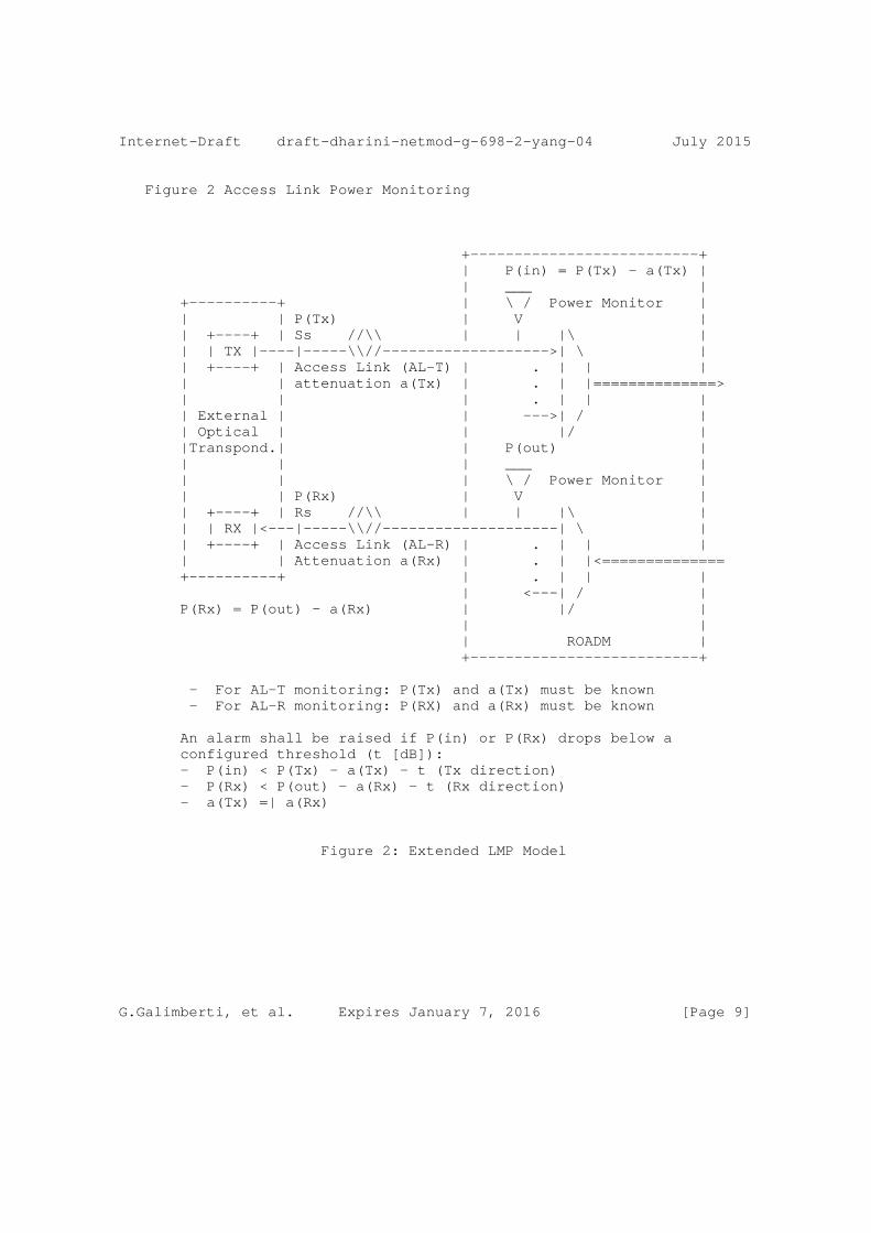
Figure 2 Access Link Power Monitoring
+--------------------------+ | P(in) = P(Tx) - a(Tx) | | ___ | +----------+ | \ / Power Monitor | | | P(Tx) | V | | +----+ | Ss //\\ | | |\ | | | TX |----|-----\\//------------------->| \ | | +----+ | Access Link (AL-T) | . | | | | | attenuation a(Tx) | . | |==============> | | | . | | | | External | | --->| / | | Optical | | |/ | |Transpond.| | P(out) | | | | ___ | | | | \ / Power Monitor | | | P(Rx) | V | | +----+ | Rs //\\ | | |\ | | | RX |<---|-----\\//--------------------| \ | | +----+ | Access Link (AL-R) | . | | | | | Attenuation a(Rx) | . | |<============== +----------+ | . | | | | <---| / | P(Rx) = P(out) - a(Rx) | |/ | | | | ROADM | +--------------------------+
- For AL-T monitoring: P(Tx) and a(Tx) must be known - For AL-R monitoring: P(RX) and a(Rx) must be known
An alarm shall be raised if P(in) or P(Rx) drops below a configured threshold (t [dB]): - P(in) < P(Tx) - a(Tx) - t (Tx direction) - P(Rx) < P(out) - a(Rx) - t (Rx direction) - a(Tx) =| a(Rx)
Figure 2: Extended LMP Model
G.Galimberti, et al. Expires January 7, 2016 [Page 9]
Internet-Draft draft-dharini-netmod-g-698-2-yang-04 July 2015
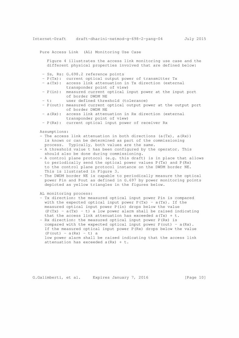
Pure Access Link (AL) Monitoring Use Case
Figure 4 illustrates the access link monitoring use case and the different physical properties involved that are defined below:
- Ss, Rs: G.698.2 reference points - P(Tx): current optical output power of transmitter Tx - a(Tx): access link attenuation in Tx direction (external transponder point of view) - P(in): measured current optical input power at the input port of border DWDM NE - t: user defined threshold (tolerance) - P(out): measured current optical output power at the output port of border DWDM NE - a(Rx): access link attenuation in Rx direction (external transponder point of view) - P(Rx): current optical input power of receiver Rx
Assumptions: - The access link attenuation in both directions (a(Tx), a(Rx)) is known or can be determined as part of the commissioning process. Typically, both values are the same. - A threshold value t has been configured by the operator. This should also be done during commissioning. - A control plane protocol (e.g. this draft) is in place that allows to periodically send the optical power values P(Tx) and P(Rx) to the control plane protocol instance on the DWDM border NE. This is llustrated in Figure 3. - The DWDM border NE is capable to periodically measure the optical power Pin and Pout as defined in G.697 by power monitoring points depicted as yellow triangles in the figures below.
AL monitoring process: - Tx direction: the measured optical input power Pin is compared with the expected optical input power P(Tx) - a(Tx). If the measured optical input power P(in) drops below the value (P(Tx) - a(Tx) - t) a low power alarm shall be raised indicating that the access link attenuation has exceeded a(Tx) + t. - Rx direction: the measured optical input power P(Rx) is compared with the expected optical input power P(out) - a(Rx). If the measured optical input power P(Rx) drops below the value (P(out) - a(Rx) - t) a low power alarm shall be raised indicating that the access link attenuation has exceeded a(Rx) + t.
G.Galimberti, et al. Expires January 7, 2016 [Page 10]
Internet-Draft draft-dharini-netmod-g-698-2-yang-04 July 2015
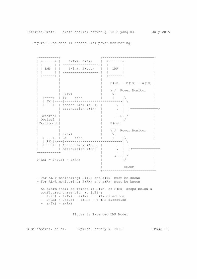
Figure 3 Use case 1: Access Link power monitoring
+----------+ +--------------------------+ | +------+ | P(Tx), P(Rx) | +-------+ | | | | | =================> | | | | | | LMP | | P(in), P(out) | | LMP | | | | | | <================= | | | | | +------+ | | +-------+ | | | | | | | | P(in) - P(Tx) - a(Tx) | | | | ___ | | | | \ / Power Monitor | | | P(Tx) | V | | +----+ | Ss //\\ | | |\ | | | TX |----|-----\\//------------------->| \ | | +----+ | Access Link (AL-T) | . | | | | | attenuation a(Tx) | . | |==============> | | | . | | | | External | | --->| / | | Optical | | |/ | |Transpond.| | P(out) | | | | ___ | | | | \ / Power Monitor | | | P(Rx) | V | | +----+ | Rs //\\ | | |\ | | | RX |<---|-----\\//--------------------| \ | | +----+ | Access Link (AL-R) | . | | | | | Attenuation a(Rx) | . | |<============== +----------+ | . | | | | <---| / | P(Rx) = P(out) - a(Rx) | |/ | | | | ROADM | +--------------------------+
- For AL-T monitoring: P(Tx) and a(Tx) must be known - For AL-R monitoring: P(RX) and a(Rx) must be known
An alarm shall be raised if P(in) or P(Rx) drops below a configured threshold (t [dB]): - P(in) < P(Tx) - a(Tx) - t (Tx direction) - P(Rx) < P(out) - a(Rx) - t (Rx direction) - a(Tx) = a(Rx)
Figure 3: Extended LMP Model
G.Galimberti, et al. Expires January 7, 2016 [Page 11]

Internet-Draft draft-dharini-netmod-g-698-2-yang-04 July 2015
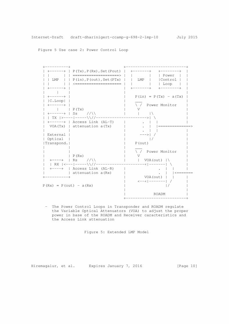
Power Control Loop Use Case
This use case is based on the access link monitoring use case as described above. In addition, the border NE is running a power control application that is capable to control the optical output power of the single channel tributary signal at the output port of the border DWDM NE (towards the external receiver Rx) and the optical output power of the single channel tributary signal at the external transmitter Tx within their known operating range. The time scale of this control loop is typically relatively slow (e.g. some 10s or minutes) because the access link attenuation is not expected to vary much over time (the attenuation only changes when re-cabling occurs). From a data plane perspective, this use case does not require additional data plane extensions. It does only require a protocol extension in the control plane (e.g. this LMP draft) that allows the power control application residing in the DWDM border NE to modify the optical output power of the DWDM domain-external transmitter Tx within the range of the currently used application code. Figure 5 below illustrates this use case utilizing the LMP protocol with extensions defined in this draft.
G.Galimberti, et al. Expires January 7, 2016 [Page 12]
Internet-Draft draft-dharini-netmod-g-698-2-yang-04 July 2015
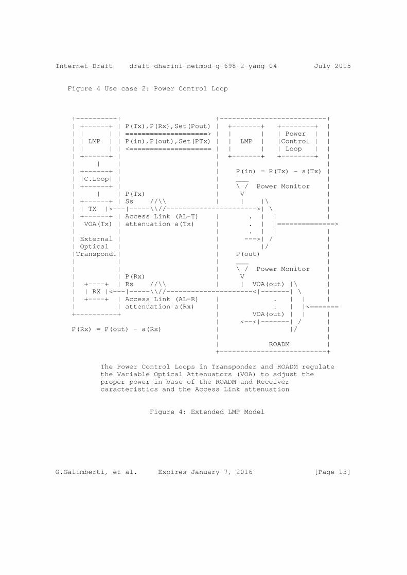
Figure 4 Use case 2: Power Control Loop
+----------+ +--------------------------+ | +------+ | P(Tx),P(Rx),Set(Pout) | +-------+ +--------+ | | | | | ====================> | | | | Power | | | | LMP | | P(in),P(out),Set(PTx) | | LMP | |Control | | | | | | <==================== | | | | Loop | | | +------+ | | +-------+ +--------+ | | | | | | | +------+ | | P(in) = P(Tx) - a(Tx) | | |C.Loop| | | ___ | | +------+ | | \ / Power Monitor | | | | P(Tx) | V | | +------+ | Ss //\\ | | |\ | | | TX |>---|-----\\//---------------------->| \ | | +------+ | Access Link (AL-T) | . | | | | VOA(Tx) | attenuation a(Tx) | . | |==============> | | | . | | | | External | | --->| / | | Optical | | |/ | |Transpond.| | P(out) | | | | ___ | | | | \ / Power Monitor | | | P(Rx) | V | | +----+ | Rs //\\ | | VOA(out) |\ | | | RX |<---|-----\\//---------------------<|-------| \ | | +----+ | Access Link (AL-R) | . | | | | | attenuation a(Rx) | . | |<======= +----------+ | VOA(out) | | | | <--<|-------| / | P(Rx) = P(out) - a(Rx) | |/ | | | | ROADM | +--------------------------+
The Power Control Loops in Transponder and ROADM regulate the Variable Optical Attenuators (VOA) to adjust the proper power in base of the ROADM and Receiver caracteristics and the Access Link attenuation
Figure 4: Extended LMP Model
G.Galimberti, et al. Expires January 7, 2016 [Page 13]
Internet-Draft draft-dharini-netmod-g-698-2-yang-04 July 2015
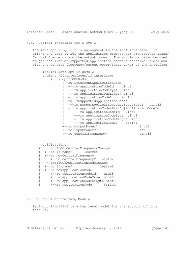
4.3. Optical Interface for G.698.2
The ietf-opt-if-g698-2 is an augment to the ietf-interface. It allows the user to set the application code/vendor transceiver class/ Central frequency and the output power. The module can also be used to get the list of supported application codes/transceiver class and also the Central frequency/output power/input power of the interface.
module: ietf-opt-if-g698-2 augment /if:interfaces/if:interface: +--rw optIfOChRsSs +--rw ifCurrentApplicationCode | +--rw applicationCodeId uint8 | +--rw applicationCodeType uint8 | +--rw applicationCodeLength uint8 | +--rw applicationCode? string +--ro ifSupportedApplicationCodes | +--ro numberApplicationCodesSupported? uint32 | +--ro applicationCodesList* [applicationCodeId] | +--ro applicationCodeId uint8 | +--rw applicationCodeType uint8 | +--rw applicationCodeLength uint8 | +--ro applicationCode? string +--rw outputPower? int32 +--ro inputPower? int32 +--rw centralFrequency? uint32
notifications: +---n optIfOChCentralFrequencyChange | +--ro if-name? leafref | +--ro newCentralFrequency | +--ro centralFrequency? uint32 +---n optIfOChApplicationCodeChange | +--ro if-name? leafref | +--ro newApplicationCode | +--ro applicationCodeId? uint8 | +--rw applicationCodeType uint8 | +--rw applicationCodeLength uint8 | +--ro applicationCode? string
5. Structure of the Yang Module
ietf-opt-if-g698-2 is a top level model for the support of this feature.
G.Galimberti, et al. Expires January 7, 2016 [Page 14]
Internet-Draft draft-dharini-netmod-g-698-2-yang-04 July 2015
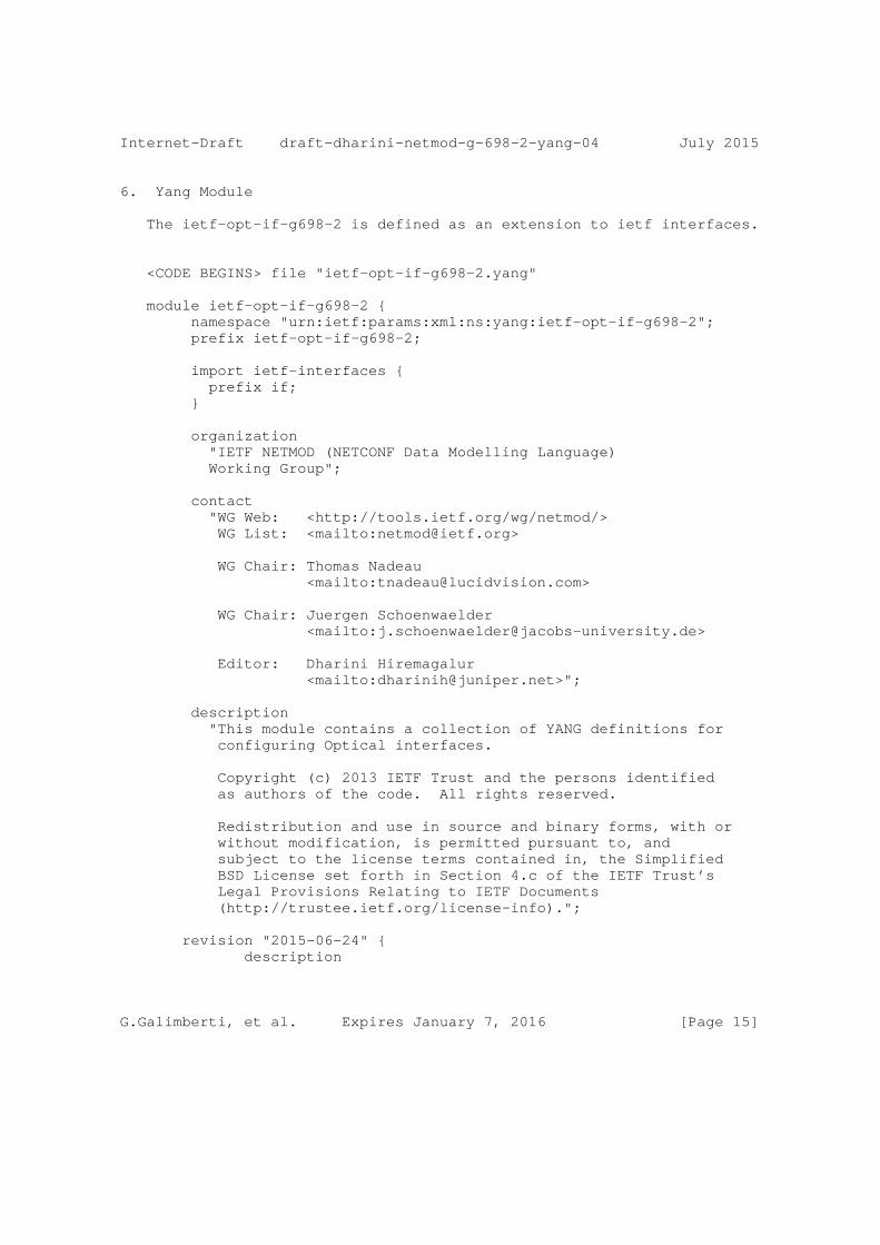
6. Yang Module
The ietf-opt-if-g698-2 is defined as an extension to ietf interfaces.
<CODE BEGINS> file "ietf-opt-if-g698-2.yang"
module ietf-opt-if-g698-2 { namespace "urn:ietf:params:xml:ns:yang:ietf-opt-if-g698-2"; prefix ietf-opt-if-g698-2;
import ietf-interfaces { prefix if; }
organization "IETF NETMOD (NETCONF Data Modelling Language) Working Group";
contact "WG Web: <http://tools.ietf.org/wg/netmod/> WG List: <mailto:[email protected]>
WG Chair: Thomas Nadeau <mailto:[email protected]>
WG Chair: Juergen Schoenwaelder <mailto:[email protected]>
Editor: Dharini Hiremagalur <mailto:[email protected]>";
description "This module contains a collection of YANG definitions for configuring Optical interfaces.
Copyright (c) 2013 IETF Trust and the persons identified as authors of the code. All rights reserved.
Redistribution and use in source and binary forms, with or without modification, is permitted pursuant to, and subject to the license terms contained in, the Simplified BSD License set forth in Section 4.c of the IETF Trust’s Legal Provisions Relating to IETF Documents (http://trustee.ietf.org/license-info).";
revision "2015-06-24" { description
G.Galimberti, et al. Expires January 7, 2016 [Page 15]
Internet-Draft draft-dharini-netmod-g-698-2-yang-04 July 2015
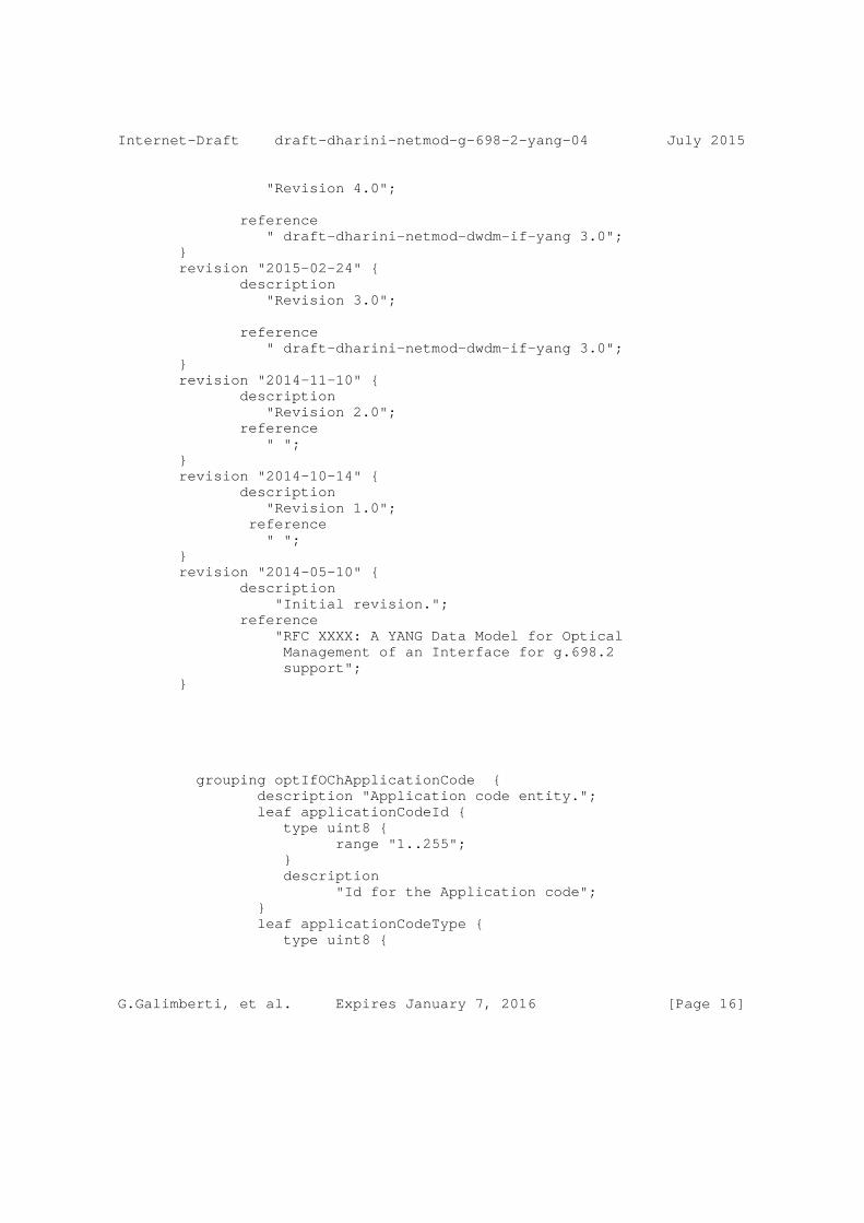
"Revision 4.0";
reference " draft-dharini-netmod-dwdm-if-yang 3.0"; } revision "2015-02-24" { description "Revision 3.0";
reference " draft-dharini-netmod-dwdm-if-yang 3.0"; } revision "2014-11-10" { description "Revision 2.0"; reference " "; } revision "2014-10-14" { description "Revision 1.0"; reference " "; } revision "2014-05-10" { description "Initial revision."; reference "RFC XXXX: A YANG Data Model for Optical Management of an Interface for g.698.2 support"; }
grouping optIfOChApplicationCode { description "Application code entity."; leaf applicationCodeId { type uint8 { range "1..255"; } description "Id for the Application code"; } leaf applicationCodeType { type uint8 {
G.Galimberti, et al. Expires January 7, 2016 [Page 16]
Internet-Draft draft-dharini-netmod-g-698-2-yang-04 July 2015
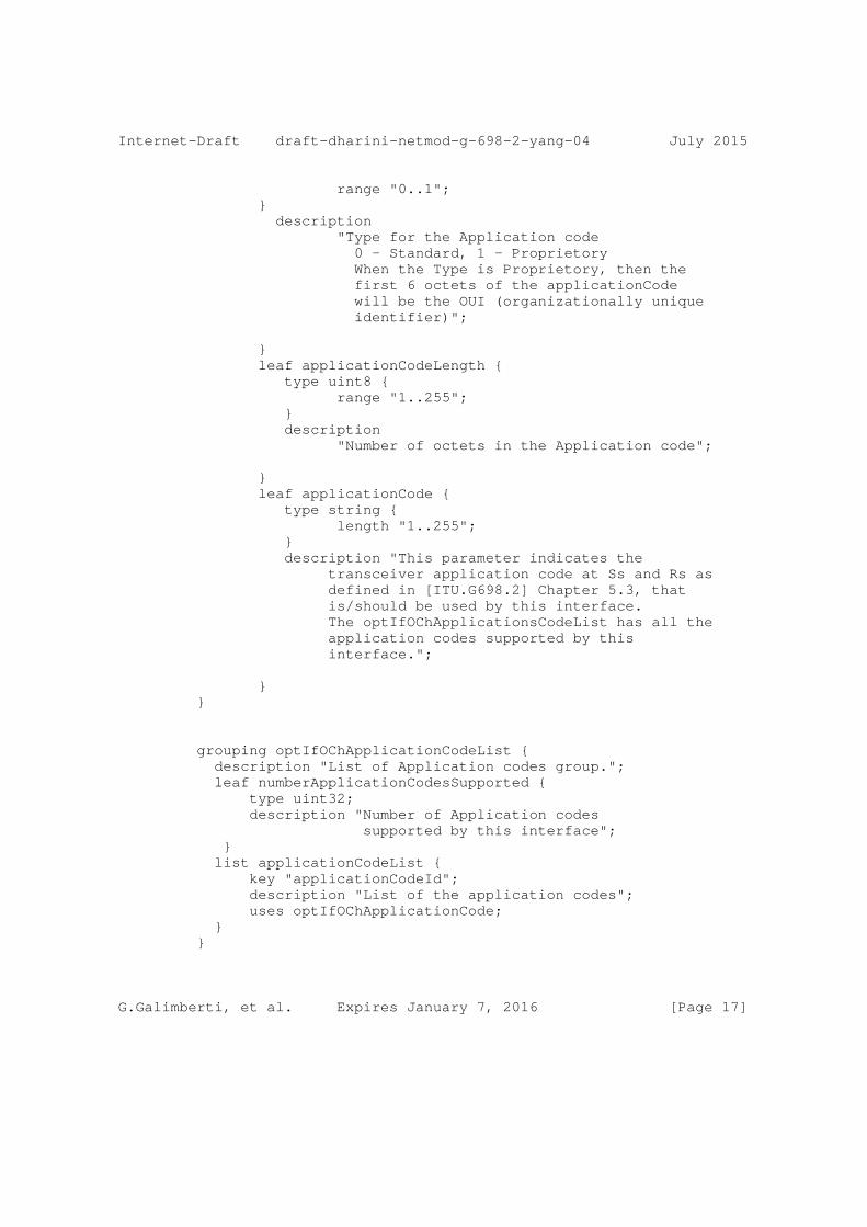
range "0..1"; } description "Type for the Application code 0 - Standard, 1 - Proprietory When the Type is Proprietory, then the first 6 octets of the applicationCode will be the OUI (organizationally unique identifier)";
} leaf applicationCodeLength { type uint8 { range "1..255"; } description "Number of octets in the Application code";
} leaf applicationCode { type string { length "1..255"; } description "This parameter indicates the transceiver application code at Ss and Rs as defined in [ITU.G698.2] Chapter 5.3, that is/should be used by this interface. The optIfOChApplicationsCodeList has all the application codes supported by this interface.";
} }
grouping optIfOChApplicationCodeList { description "List of Application codes group."; leaf numberApplicationCodesSupported { type uint32; description "Number of Application codes supported by this interface"; } list applicationCodeList { key "applicationCodeId"; description "List of the application codes"; uses optIfOChApplicationCode; } }
G.Galimberti, et al. Expires January 7, 2016 [Page 17]
Internet-Draft draft-dharini-netmod-g-698-2-yang-04 July 2015
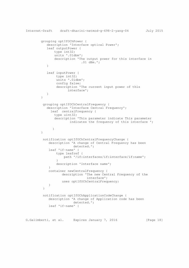
grouping optIfOChPower { description "Interface optical Power"; leaf outputPower { type int32; units ".01dbm"; description "The output power for this interface in .01 dBm."; }
leaf inputPower { type int32; units ".01dbm"; config false; description "The current input power of this interface"; } }
grouping optIfOChCentralFrequency { description "Interface Central Frequency"; leaf centralFrequency { type uint32; description "This parameter indicate This parameter indicates the frequency of this interface ";
} }
notification optIfOChCentralFrequencyChange { description "A change of Central Frequency has been detected."; leaf "if-name" { type leafref { path "/if:interfaces/if:interface/if:name"; } description "Interface name"; } container newCentralFrequency { description "The new Central Frequency of the interface"; uses optIfOChCentralFrequency; } }
notification optIfOChApplicationCodeChange { description "A change of Application code has been detected."; leaf "if-name" {
G.Galimberti, et al. Expires January 7, 2016 [Page 18]
Internet-Draft draft-dharini-netmod-g-698-2-yang-04 July 2015
type leafref { path "/if:interfaces/if:interface/if:name"; } description "Interface name"; } container newApplicationCode { description "The new application code for the interface"; uses optIfOChApplicationCode; } }
augment "/if:interfaces/if:interface" { description "Parameters for an optical interface"; container optIfOChRsSs { description "RsSs path configuration for an interface"; container ifCurrentApplicationCode { description "Current Application code of the interface"; uses optIfOChApplicationCode; }
container ifSupportedApplicationCodes { config false; description "Supported Application codes of the interface"; uses optIfOChApplicationCodeList; }
uses optIfOChPower;
uses optIfOChCentralFrequency;
} } }
<CODE ENDS>
7. Security Considerations
The YANG module defined in this memo is designed to be accessed via the NETCONF protocol [RFC6241]. he lowest NETCONF layer is the secure transport layer and the mandatory-to-implement secure transport is SSH [RFC6242]. The NETCONF access control model [RFC6536] provides
G.Galimberti, et al. Expires January 7, 2016 [Page 19]

Internet-Draft draft-dharini-netmod-g-698-2-yang-04 July 2015
the means to restrict access for particular NETCONF users to a pre- configured subset of all available NETCONF protocol operation and content.
8. IANA Considerations
This document registers a URI in the IETF XML registry [RFC3688]. Following the format in [RFC3688], the following registration is requested to be made:
URI: urn:ietf:params:xml:ns:yang:ietf-interfaces:ietf-opt-if-g698-2
Registrant Contact: The IESG.
XML: N/A, the requested URI is an XML namespace.
This document registers a YANG module in the YANG Module Names registry [RFC6020].
This document registers a YANG module in the YANG Module Names registry [RFC6020].
prefix: ietf-opt-if-g698-2 reference: RFC XXXX
9. Acknowledgements
Gert Grammel is partly funded by European Union Seventh Framework Programme under grant agreement 318514 CONTENT.
10. Contributors
G.Galimberti, et al. Expires January 7, 2016 [Page 20]
Internet-Draft draft-dharini-netmod-g-698-2-yang-04 July 2015
Dean Bogdanovic Juniper Networks Westford U.S.A. email [email protected]
Bernd Zeuner Deutsche Telekom Darmstadt Germany email [email protected]
Arnold Mattheus Deutsche Telekom Darmstadt Germany email [email protected]
Manuel Paul Deutsche Telekom Berlin Germany email [email protected]
Walid Wakim Cisco 9501 Technology Blvd ROSEMONT, ILLINOIS 60018 UNITED STATES email [email protected]
11. References
11.1. Normative References
[RFC2863] McCloghrie, K. and F. Kastenholz, "The Interfaces Group MIB", RFC 2863, June 2000.
[RFC2119] Bradner, S., "Key words for use in RFCs to Indicate Requirement Levels", BCP 14, RFC 2119, March 1997.
[RFC2578] McCloghrie, K., Ed., Perkins, D., Ed., and J. Schoenwaelder, Ed., "Structure of Management Information Version 2 (SMIv2)", STD 58, RFC 2578, April 1999.
G.Galimberti, et al. Expires January 7, 2016 [Page 21]
Internet-Draft draft-dharini-netmod-g-698-2-yang-04 July 2015
[RFC2579] McCloghrie, K., Ed., Perkins, D., Ed., and J. Schoenwaelder, Ed., "Textual Conventions for SMIv2", STD 58, RFC 2579, April 1999.
[RFC2580] McCloghrie, K., Perkins, D., and J. Schoenwaelder, "Conformance Statements for SMIv2", STD 58, RFC 2580, April 1999.
[RFC3591] Lam, H-K., Stewart, M., and A. Huynh, "Definitions of Managed Objects for the Optical Interface Type", RFC 3591, September 2003.
[RFC6205] Otani, T. and D. Li, "Generalized Labels for Lambda- Switch-Capable (LSC) Label Switching Routers", RFC 6205, March 2011.
[ITU.G698.2] International Telecommunications Union, "Amplified multichannel dense wavelength division multiplexing applications with single channel optical interfaces", ITU-T Recommendation G.698.2, November 2009.
[ITU.G709] International Telecommunications Union, "Interface for the Optical Transport Network (OTN)", ITU-T Recommendation G.709, March 2003.
[ITU.G872] International Telecommunications Union, "Architecture of optical transport networks", ITU-T Recommendation G.872, November 2001.
[ITU.G798] International Telecommunications Union, "Characteristics of optical transport network hierarchy equipment functional blocks", ITU-T Recommendation G.798, October 2010.
[ITU.G874] International Telecommunications Union, "Management aspects of optical transport network elements", ITU-T Recommendation G.874, July 2010.
[ITU.G874.1] International Telecommunications Union, "Optical transport network (OTN): Protocol-neutral management information model for the network element view", ITU-T Recommendation G.874.1, January 2002.
G.Galimberti, et al. Expires January 7, 2016 [Page 22]
Internet-Draft draft-dharini-netmod-g-698-2-yang-04 July 2015
[ITU.G959.1] International Telecommunications Union, "Optical transport network physical layer interfaces", ITU-T Recommendation G.959.1, November 2009.
[ITU.G826] International Telecommunications Union, "End-to-end error performance parameters and objectives for international, constant bit-rate digital paths and connections", ITU-T Recommendation G.826, November 2009.
[ITU.G8201] International Telecommunications Union, "Error performance parameters and objectives for multi-operator international paths within the Optical Transport Network (OTN)", ITU-T Recommendation G.8201, April 2011.
[ITU.G694.1] International Telecommunications Union, "Spectral grids for WDM applications: DWDM frequency grid", ITU-T Recommendation G.694.1, June 2002.
[ITU.G7710] International Telecommunications Union, "Common equipment management function requirements", ITU-T Recommendation G.7710, May 2008.
11.2. Informative References
[RFC3410] Case, J., Mundy, R., Partain, D., and B. Stewart, "Introduction and Applicability Statements for Internet- Standard Management Framework", RFC 3410, December 2002.
[RFC2629] Rose, M., "Writing I-Ds and RFCs using XML", RFC 2629, June 1999.
[RFC4181] Heard, C., "Guidelines for Authors and Reviewers of MIB Documents", BCP 111, RFC 4181, September 2005.
[I-D.kunze-g-698-2-management-control-framework] Kunze, R., "A framework for Management and Control of optical interfaces supporting G.698.2", draft-kunze- g-698-2-management-control-framework-00 (work in progress), July 2011.
[RFC4054] Strand, J. and A. Chiu, "Impairments and Other Constraints on Optical Layer Routing", RFC 4054, May 2005.
G.Galimberti, et al. Expires January 7, 2016 [Page 23]
Internet-Draft draft-dharini-netmod-g-698-2-yang-04 July 2015
Appendix A. Change Log
This optional section should be removed before the internet draft is submitted to the IESG for publication as an RFC.
Note to RFC Editor: please remove this appendix before publication as an RFC.
Appendix B. Open Issues
Note to RFC Editor: please remove this appendix before publication as an RFC.
Authors’ Addresses
Gabriele Galimberti (editor) Cisco Via Santa Maria Molgora, 48 c 20871 - Vimercate Italy
Phone: +390392091462 Email: [email protected]
Ruediger Kunze (editor) Deutsche Telekom Dddd, xx Berlin Germany
Phone: +49xxxxxxxxxx Email: [email protected]
Kam Lam (editor) Alcatel-Lucent USA
Phone: +1 732 331 3476 Email: [email protected]
G.Galimberti, et al. Expires January 7, 2016 [Page 24]
Internet-Draft draft-dharini-netmod-g-698-2-yang-04 July 2015
Dharini Hiremagalur (editor) Juniper 1194 N Mathilda Avenue Sunnyvale - 94089 California USA
Email: [email protected]
Gert Grammel (editor) Juniper Oskar-Schlemmer Str. 15 80807 Muenchen Germany
Phone: +49 1725186386 Email: [email protected]
Luyuan Fang (editor) Microsoft 5600 148th Ave NE Redmond, WA 98502 USA
Email: [email protected]
Gary Ratterree (editor) Microsoft 5600 148th Ave NE Redmond, WA 98502 USA
Email: [email protected]
G.Galimberti, et al. Expires January 7, 2016 [Page 25]
Internet Engineering Task Force D. Hiremagalur, Ed.Internet-Draft G. Grammel, Ed.Intended status: Standards Track JuniperExpires: January 7, 2016 G. Galimberti, Ed. Z. Ali, Ed. Cisco R. Kunze, Ed. Deutsche Telekom D. Beller, Ed. ALU July 6, 2015
Extension to the Link Management Protocol (LMP/DWDM -rfc4209) for Dense Wavelength Division Multiplexing (DWDM) Optical Line Systems to managethe application code of optical interface parameters in DWDM application draft-dharinigert-ccamp-g-698-2-lmp-10
Abstract
This memo defines extensions to LMP(rfc4209) for managing Optical parameters associated with Wavelength Division Multiplexing (WDM) systems or characterized by the Optical Transport Network (OTN) in accordance with the Interface Application Code approach defined in ITU-T Recommendation G.698.2.[ITU.G698.2], G.694.1.[ITU.G694.1] and its extensions.
Copyright Notice
Copyright (c) 2011 IETF Trust and the persons identified as the document authors. All rights reserved.
Status of This Memo
This Internet-Draft is submitted in full conformance with the provisions of BCP 78 and BCP 79.
Internet-Drafts are working documents of the Internet Engineering Task Force (IETF). Note that other groups may also distribute working documents as Internet-Drafts. The list of current Internet- Drafts is at http://datatracker.ietf.org/drafts/current/.
Internet-Drafts are draft documents valid for a maximum of six months and may be updated, replaced, or obsoleted by other documents at any time. It is inappropriate to use Internet-Drafts as reference material or to cite them other than as "work in progress."
This Internet-Draft will expire on January 7, 2016.
Hiremagalur, et al. Expires January 7, 2016 [Page 1]

Internet-Draft draft-dharinigert-ccamp-g-698-2-lmp-10 July 2015
Copyright Notice
Copyright (c) 2015 IETF Trust and the persons identified as the document authors. All rights reserved.
This document is subject to BCP 78 and the IETF Trust’s Legal Provisions Relating to IETF Documents (http://trustee.ietf.org/license-info) in effect on the date of publication of this document. Please review these documents carefully, as they describe your rights and restrictions with respect to this document. Code Components extracted from this document must include Simplified BSD License text as described in Section 4.e of the Trust Legal Provisions and are provided without warranty as described in the Simplified BSD License.
Table of Contents
1. Introduction . . . . . . . . . . . . . . . . . . . . . . . . 2 2. Use Cases . . . . . . . . . . . . . . . . . . . . . . . . . . 4 3. Extensions to LMP-WDM Protocol . . . . . . . . . . . . . . . 11 4. General Parameters - OCh_General . . . . . . . . . . . . . . 11 5. ApplicationIdentifier - OCh_ApplicationIdentifier . . . . . . 13 6. OCh_Ss - OCh transmit parameters . . . . . . . . . . . . . . 15 7. OCh_Rs - receive parameters . . . . . . . . . . . . . . . . . 15 8. Security Considerations . . . . . . . . . . . . . . . . . . . 16 9. IANA Considerations . . . . . . . . . . . . . . . . . . . . . 16 10. Contributors . . . . . . . . . . . . . . . . . . . . . . . . 17 11. References . . . . . . . . . . . . . . . . . . . . . . . . . 17 11.1. Normative References . . . . . . . . . . . . . . . . . . 17 11.2. Informative References . . . . . . . . . . . . . . . . . 18 Authors’ Addresses . . . . . . . . . . . . . . . . . . . . . . . 18
1. Introduction
This extension is based on "draft-galikunze-ccamp-g-698-2-snmp-mib- 10", for the relevant interface optical parameters described in recommendations like ITU-T G.698.2 [ITU.G698.2] and G.694.1.[ITU.G694.1]. The LMP Model from RFC4902 provides link property correlation between a client and an OLS device. LMP link property correlation, exchanges the capabilities of either end of the link where the term ’link’ refers to the attachment link between OXC and OLS (see Figure 1). By performing link property correlation, both ends of the link exchange link properties, such as application identifiers. This allows either end to operate within a commonly understood parameter window. Based on known parameter limits, each device can supervise the received signal for conformance using mechanisms defined in RFC3591. For example if the Client transmitter power (OXC1) has a value of 0dBm and the ROADM interface measured
Hiremagalur, et al. Expires January 7, 2016 [Page 2]
Internet-Draft draft-dharinigert-ccamp-g-698-2-lmp-10 July 2015
power (at OLS1) is -6dBm the fiber patch cord connecting the two nodes may be pinched or the connectors are dirty. More, the interface characteristics can be used by the OLS network Control Plane in order to check the Optical Channels feasibility. Finally the OXC1 transceivers parameters (Application Code) can be shared with OXC2 using the LMP protocol to verify the Transceivers compatibility. The actual route selection of a specific wavelength within the allowed set is outside the scope of LMP. In GMPLS, the parameter selection (e.g. central frequency) is performed by RSVP-TE.
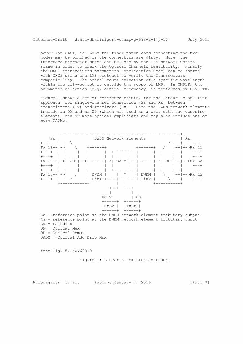
Figure 1 shows a set of reference points, for the linear "black link" approach, for single-channel connection (Ss and Rs) between transmitters (Tx) and receivers (Rx). Here the DWDM network elements include an OM and an OD (which are used as a pair with the opposing element), one or more optical amplifiers and may also include one or more OADMs.
+-------------------------------------------------+ Ss | DWDM Network Elements | Rs +--+ | | | \ / | | | +--+ Tx L1--|->| \ +------+ +------+ / |--|-->Rx L1 +---+ | | | | | +------+ | | | | | +--+ +---+ | | | | | | | | | | | | +--+ Tx L2--|->| OM |-->|------|->| OADM |--|------|->| OD |--|-->Rx L2 +---+ | | | | | | | | | | | | +--+ +---+ | | | | | +------+ | | | | | +--+ Tx L3--|->| / | DWDM | | ^ | DWDM | \ |--|-->Rx L3 +---+ | | / | Link +----|--|----+ Link | \ | | +--+ +-----------+ | | +----------+ +--+ +--+ | | Rs v | Ss +-----+ +-----+ |RxLx | |TxLx | +-----+ +-----+ Ss = reference point at the DWDM network element tributary output Rs = reference point at the DWDM network element tributary input Lx = Lambda x OM = Optical Mux OD = Optical Demux OADM = Optical Add Drop Mux
from Fig. 5.1/G.698.2
Figure 1: Linear Black Link approach
Hiremagalur, et al. Expires January 7, 2016 [Page 3]
Internet-Draft draft-dharinigert-ccamp-g-698-2-lmp-10 July 2015
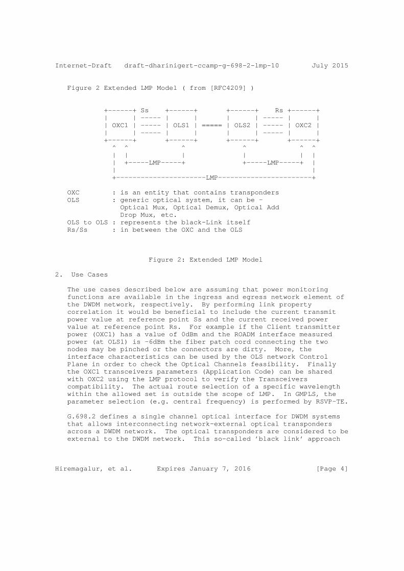
Figure 2 Extended LMP Model ( from [RFC4209] )
+------+ Ss +------+ +------+ Rs +------+ | | ----- | | | | ----- | | | OXC1 | ----- | OLS1 | ===== | OLS2 | ----- | OXC2 | | | ----- | | | | ----- | | +------+ +------+ +------+ +------+ ^ ^ ^ ^ ^ ^ | | | | | | | +-----LMP-----+ +-----LMP-----+ | | | +----------------------LMP-----------------------+
OXC : is an entity that contains transponders OLS : generic optical system, it can be - Optical Mux, Optical Demux, Optical Add Drop Mux, etc. OLS to OLS : represents the black-Link itself Rs/Ss : in between the OXC and the OLS
Figure 2: Extended LMP Model
2. Use Cases
The use cases described below are assuming that power monitoring functions are available in the ingress and egress network element of the DWDM network, respectively. By performing link property correlation it would be beneficial to include the current transmit power value at reference point Ss and the current received power value at reference point Rs. For example if the Client transmitter power (OXC1) has a value of 0dBm and the ROADM interface measured power (at OLS1) is -6dBm the fiber patch cord connecting the two nodes may be pinched or the connectors are dirty. More, the interface characteristics can be used by the OLS network Control Plane in order to check the Optical Channels feasibility. Finally the OXC1 transceivers parameters (Application Code) can be shared with OXC2 using the LMP protocol to verify the Transceivers compatibility. The actual route selection of a specific wavelength within the allowed set is outside the scope of LMP. In GMPLS, the parameter selection (e.g. central frequency) is performed by RSVP-TE.
G.698.2 defines a single channel optical interface for DWDM systems that allows interconnecting network-external optical transponders across a DWDM network. The optical transponders are considered to be external to the DWDM network. This so-called ’black link’ approach
Hiremagalur, et al. Expires January 7, 2016 [Page 4]

Internet-Draft draft-dharinigert-ccamp-g-698-2-lmp-10 July 2015
illustrated in Figure 5-1 of G.698.2 and a copy of this figure is provided below. The single channel fiber link between the Ss/Rs reference points and the ingress/egress port of the network element on the domain boundary of the DWDM network (DWDM border NE) is called access link in this contribution. Based on the definition in G.698.2 it is considered to be part of the DWDM network. The access link typically is realized as a passive fiber link that has a specific optical attenuation (insertion loss). As the access link is an integral part of the DWDM network, it is desirable to monitor its attenuation. Therefore, it is useful to detect an increase of the access link attenuation, for example, when the access link fiber has been disconnected and reconnected (maintenance) and a bad patch panel connection (connector) resulted in a significantly higher access link attenuation (loss of signal in the extreme case of an open connector or a fiber cut). In the following section, two use cases are presented and discussed:
1) pure access link monitoring 2) access link monitoring with a power control loop
These use cases require a power monitor as described in G.697 (see section 6.1.2), that is capable to measure the optical power of the incoming or outgoing single channel signal. The use case where a power control loop is in place could even be used to compensate an increased attenuation as long as the optical transmitter can still be operated within its output power range defined by its application code.
Hiremagalur, et al. Expires January 7, 2016 [Page 5]
Internet-Draft draft-dharinigert-ccamp-g-698-2-lmp-10 July 2015
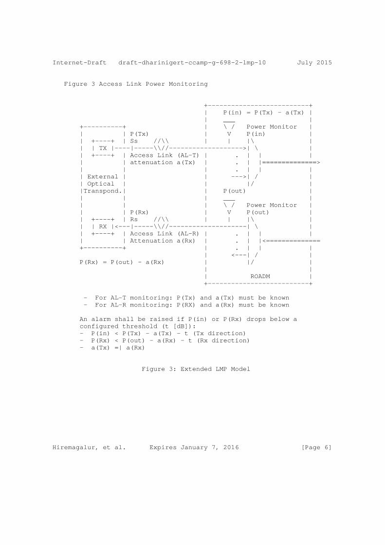
Figure 3 Access Link Power Monitoring
+--------------------------+ | P(in) = P(Tx) - a(Tx) | | ___ | +----------+ | \ / Power Monitor | | | P(Tx) | V P(in) | | +----+ | Ss //\\ | | |\ | | | TX |----|-----\\//------------------->| \ | | +----+ | Access Link (AL-T) | . | | | | | attenuation a(Tx) | . | |==============> | | | . | | | | External | | --->| / | | Optical | | |/ | |Transpond.| | P(out) | | | | ___ | | | | \ / Power Monitor | | | P(Rx) | V P(out) | | +----+ | Rs //\\ | | |\ | | | RX |<---|-----\\//--------------------| \ | | +----+ | Access Link (AL-R) | . | | | | | Attenuation a(Rx) | . | |<============== +----------+ | . | | | | <---| / | P(Rx) = P(out) - a(Rx) | |/ | | | | ROADM | +--------------------------+
- For AL-T monitoring: P(Tx) and a(Tx) must be known - For AL-R monitoring: P(RX) and a(Rx) must be known
An alarm shall be raised if P(in) or P(Rx) drops below a configured threshold (t [dB]): - P(in) < P(Tx) - a(Tx) - t (Tx direction) - P(Rx) < P(out) - a(Rx) - t (Rx direction) - a(Tx) =| a(Rx)
Figure 3: Extended LMP Model
Hiremagalur, et al. Expires January 7, 2016 [Page 6]
Internet-Draft draft-dharinigert-ccamp-g-698-2-lmp-10 July 2015
Pure Access Link (AL) Monitoring Use Case
Figure 4 illustrates the access link monitoring use case and the different physical properties involved that are defined below:
- Ss, Rs: G.698.2 reference points - P(Tx): current optical output power of transmitter Tx - a(Tx): access link attenuation in Tx direction (external transponder point of view) - P(in): measured current optical input power at the input port of border DWDM NE - t: user defined threshold (tolerance) - P(out): measured current optical output power at the output port of border DWDM NE - a(Rx): access link attenuation in Rx direction (external transponder point of view) - P(Rx): current optical input power of receiver Rx
Assumptions: - The access link attenuation in both directions (a(Tx), a(Rx)) is known or can be determined as part of the commissioning process. Typically, both values are the same. - A threshold value t has been configured by the operator. This should also be done during commissioning. - A control plane protocol (e.g. this draft) is in place that allows to periodically send the optical power values P(Tx) and P(Rx) to the control plane protocol instance on the DWDM border NE. This is llustrated in Figure 3. - The DWDM border NE is capable to periodically measure the optical power Pin and Pout as defined in G.697 by power monitoring points depicted as yellow triangles in the figures below.
AL monitoring process: - Tx direction: the measured optical input power Pin is compared with the expected optical input power P(Tx) - a(Tx). If the measured optical input power P(in) drops below the value (P(Tx) - a(Tx) - t) a low power alarm shall be raised indicating that the access link attenuation has exceeded a(Tx) + t. - Rx direction: the measured optical input power P(Rx) is compared with the expected optical input power P(out) - a(Rx). If the measured optical input power P(Rx) drops below the value (P(out) - a(Rx) - t) a low power alarm shall be raised indicating that the access link attenuation has exceeded a(Rx) + t.
Hiremagalur, et al. Expires January 7, 2016 [Page 7]
Internet-Draft draft-dharinigert-ccamp-g-698-2-lmp-10 July 2015
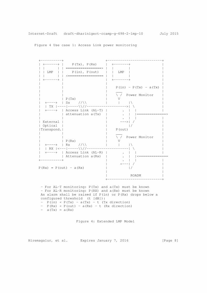
Figure 4 Use case 1: Access Link power monitoring
+----------+ +--------------------------+ | +------+ | P(Tx), P(Rx) | +-------+ | | | | | =================> | | | | | | LMP | | P(in), P(out) | | LMP | | | | | | <================= | | | | | +------+ | | +-------+ | | | | | | | | P(in) - P(Tx) - a(Tx) | | | | ___ | | | | \ / Power Monitor | | | P(Tx) | V | | +----+ | Ss //\\ | | |\ | | | TX |----|-----\\//------------------->| \ | | +----+ | Access Link (AL-T) | . | | | | | attenuation a(Tx) | . | |==============> | | | . | | | | External | | --->| / | | Optical | | |/ | |Transpond.| | P(out) | | | | ___ | | | | \ / Power Monitor | | | P(Rx) | V | | +----+ | Rs //\\ | | |\ | | | RX |<---|-----\\//--------------------| \ | | +----+ | Access Link (AL-R) | . | | | | | Attenuation a(Rx) | . | |<============== +----------+ | . | | | | <---| / | P(Rx) = P(out) - a(Rx) | |/ | | | | ROADM | +--------------------------+
- For AL-T monitoring: P(Tx) and a(Tx) must be known - For AL-R monitoring: P(RX) and a(Rx) must be known An alarm shall be raised if P(in) or P(Rx) drops below a configured threshold (t [dB]): - P(in) < P(Tx) - a(Tx) - t (Tx direction) - P(Rx) < P(out) - a(Rx) - t (Rx direction) - a(Tx) = a(Rx)
Figure 4: Extended LMP Model
Hiremagalur, et al. Expires January 7, 2016 [Page 8]

Internet-Draft draft-dharinigert-ccamp-g-698-2-lmp-10 July 2015
Power Control Loop Use Case
This use case is based on the access link monitoring use case as described above. In addition, the border NE is running a power control application that is capable to control the optical output power of the single channel tributary signal at the output port of the border DWDM NE (towards the external receiver Rx) and the optical output power of the single channel tributary signal at the external transmitter Tx within their known operating range. The time scale of this control loop is typically relatively slow (e.g. some 10s or minutes) because the access link attenuation is not expected to vary much over time (the attenuation only changes when re-cabling occurs). From a data plane perspective, this use case does not require additional data plane extensions. It does only require a protocol extension in the control plane (e.g. this LMP draft) that allows the power control application residing in the DWDM border NE to modify the optical output power of the DWDM domain-external transmitter Tx within the range of the currently used application code. Figure 5 below illustrates this use case utilizing the LMP protocol with extensions defined in this draft.
Hiremagalur, et al. Expires January 7, 2016 [Page 9]
Internet-Draft draft-dharinigert-ccamp-g-698-2-lmp-10 July 2015
Figure 5 Use case 2: Power Control Loop
+----------+ +--------------------------+ | +------+ | P(Tx),P(Rx),Set(Pout) | +-------+ +--------+ | | | | | ====================> | | | | Power | | | | LMP | | P(in),P(out),Set(PTx) | | LMP | |Control | | | | | | <==================== | | | | Loop | | | +------+ | | +-------+ +--------+ | | | | | | | +------+ | | P(in) = P(Tx) - a(Tx) | | |C.Loop| | | ___ | | +------+ | | \ / Power Monitor | | | | P(Tx) | V | | +------+ | Ss //\\ | | |\ | | | TX |>----|-----\\//---------------------->| \ | | +------+ | Access Link (AL-T) | . | | | | VOA(Tx) | attenuation a(Tx) | . | |==============> | | | . | | | | External | | --->| / | | Optical | | |/ | |Transpond.| | P(out) | | | | ___ | | | | \ / Power Monitor | | | P(Rx) | V | | +----+ | Rs //\\ | | VOA(out) |\ | | | RX |<---|-----\\//---------------------<|-------| \ | | +----+ | Access Link (AL-R) | . | | | | | attenuation a(Rx) | . | |<======= +----------+ | VOA(out) | | | | <--<|-------| / | P(Rx) = P(out) - a(Rx) | |/ | | | | ROADM | +--------------------------+
- The Power Control Loops in Transponder and ROADM regulate the Variable Optical Attenuators (VOA) to adjust the proper power in base of the ROADM and Receiver caracteristics and the Access Link attenuation
Figure 5: Extended LMP Model
Hiremagalur, et al. Expires January 7, 2016 [Page 10]
Internet-Draft draft-dharinigert-ccamp-g-698-2-lmp-10 July 2015
3. Extensions to LMP-WDM Protocol
This document defines extensions to [RFC4209] to allow the Black Link (BL) parameters of G.698.2, to be exchanged between a router or optical switch and the optical line system to which it is attached. In particular, this document defines additional Data Link sub-objects to be carried in the LinkSummary message defined in [RFC4204] and [RFC6205]. The OXC and OLS systems may be managed by different Network management systems and hence may not know the capability and status of their peer. The intent of this draft is to enable the OXC and OLS systems to exchange this information. These messages and their usage are defined in subsequent sections of this document.
The following new messages are defined for the WDM extension for ITU-T G.698.2 [ITU.G698.2]/ITU-T G.698.1 [ITU.G698.1]/ ITU-T G.959.1 [ITU.G959.1] - OCh_General (sub-object Type = TBA) - OCh_ApplicationIdentier (sub-object Type = TBA) - OCh_Ss (sub-object Type = TBA) - OCh_Rs (sub-object Type = TBA)
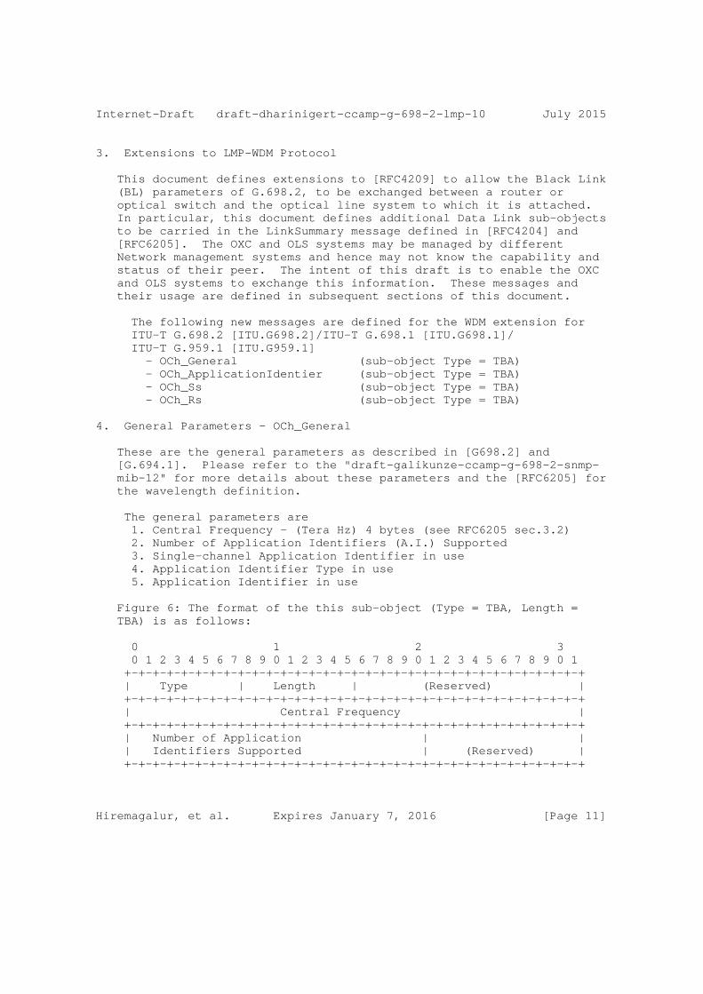
4. General Parameters - OCh_General
These are the general parameters as described in [G698.2] and [G.694.1]. Please refer to the "draft-galikunze-ccamp-g-698-2-snmp- mib-12" for more details about these parameters and the [RFC6205] for the wavelength definition.
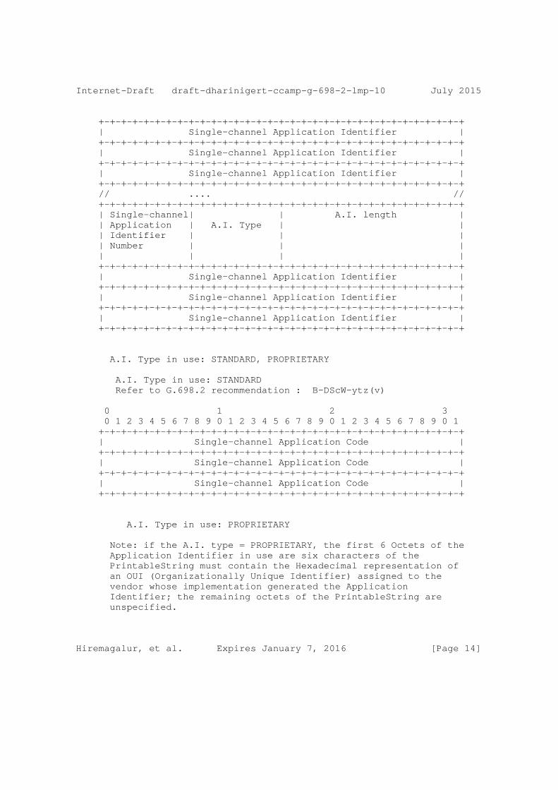
The general parameters are 1. Central Frequency - (Tera Hz) 4 bytes (see RFC6205 sec.3.2) 2. Number of Application Identifiers (A.I.) Supported 3. Single-channel Application Identifier in use 4. Application Identifier Type in use 5. Application Identifier in use
Figure 6: The format of the this sub-object (Type = TBA, Length = TBA) is as follows:
0 1 2 3 0 1 2 3 4 5 6 7 8 9 0 1 2 3 4 5 6 7 8 9 0 1 2 3 4 5 6 7 8 9 0 1 +-+-+-+-+-+-+-+-+-+-+-+-+-+-+-+-+-+-+-+-+-+-+-+-+-+-+-+-+-+-+-+-+ | Type | Length | (Reserved) | +-+-+-+-+-+-+-+-+-+-+-+-+-+-+-+-+-+-+-+-+-+-+-+-+-+-+-+-+-+-+-+-+ | Central Frequency | +-+-+-+-+-+-+-+-+-+-+-+-+-+-+-+-+-+-+-+-+-+-+-+-+-+-+-+-+-+-+-+-+ | Number of Application | | | Identifiers Supported | (Reserved) | +-+-+-+-+-+-+-+-+-+-+-+-+-+-+-+-+-+-+-+-+-+-+-+-+-+-+-+-+-+-+-+-+
Hiremagalur, et al. Expires January 7, 2016 [Page 11]
Internet-Draft draft-dharinigert-ccamp-g-698-2-lmp-10 July 2015
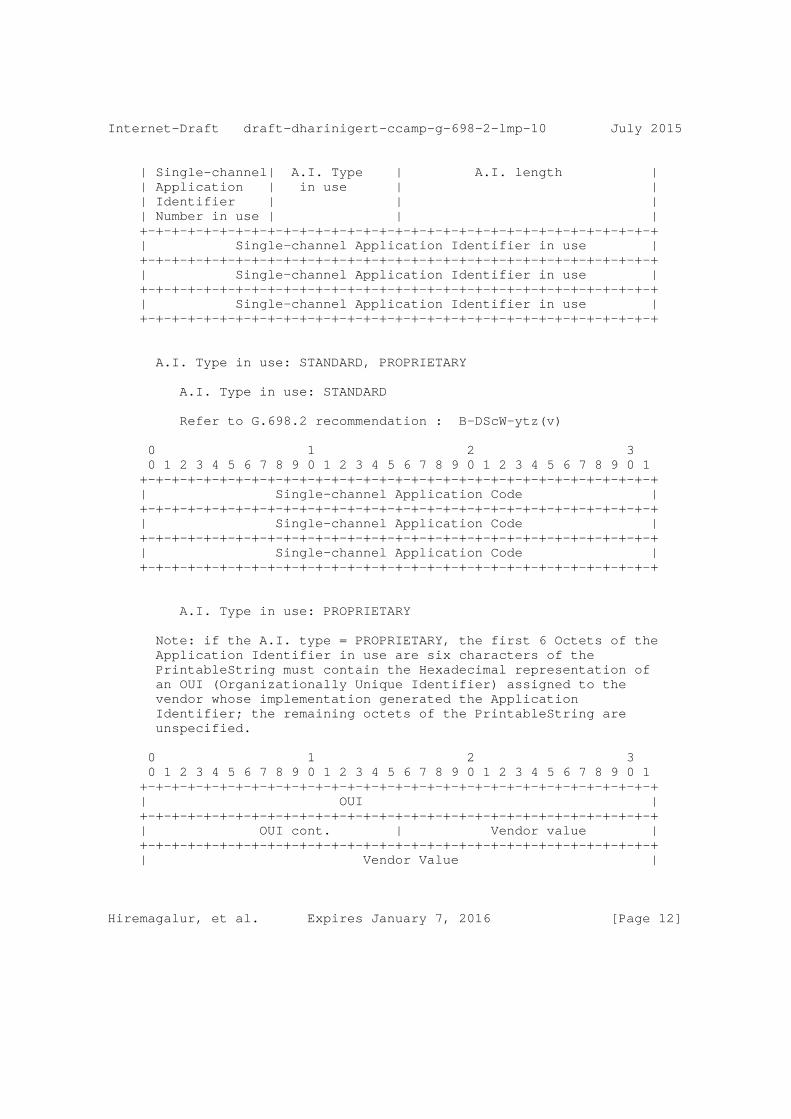
| Single-channel| A.I. Type | A.I. length | | Application | in use | | | Identifier | | | | Number in use | | | +-+-+-+-+-+-+-+-+-+-+-+-+-+-+-+-+-+-+-+-+-+-+-+-+-+-+-+-+-+-+-+-+ | Single-channel Application Identifier in use | +-+-+-+-+-+-+-+-+-+-+-+-+-+-+-+-+-+-+-+-+-+-+-+-+-+-+-+-+-+-+-+-+ | Single-channel Application Identifier in use | +-+-+-+-+-+-+-+-+-+-+-+-+-+-+-+-+-+-+-+-+-+-+-+-+-+-+-+-+-+-+-+-+ | Single-channel Application Identifier in use | +-+-+-+-+-+-+-+-+-+-+-+-+-+-+-+-+-+-+-+-+-+-+-+-+-+-+-+-+-+-+-+-+
A.I. Type in use: STANDARD, PROPRIETARY
A.I. Type in use: STANDARD
Refer to G.698.2 recommendation : B-DScW-ytz(v)
0 1 2 3 0 1 2 3 4 5 6 7 8 9 0 1 2 3 4 5 6 7 8 9 0 1 2 3 4 5 6 7 8 9 0 1 +-+-+-+-+-+-+-+-+-+-+-+-+-+-+-+-+-+-+-+-+-+-+-+-+-+-+-+-+-+-+-+-+ | Single-channel Application Code | +-+-+-+-+-+-+-+-+-+-+-+-+-+-+-+-+-+-+-+-+-+-+-+-+-+-+-+-+-+-+-+-+ | Single-channel Application Code | +-+-+-+-+-+-+-+-+-+-+-+-+-+-+-+-+-+-+-+-+-+-+-+-+-+-+-+-+-+-+-+-+ | Single-channel Application Code | +-+-+-+-+-+-+-+-+-+-+-+-+-+-+-+-+-+-+-+-+-+-+-+-+-+-+-+-+-+-+-+-+
A.I. Type in use: PROPRIETARY
Note: if the A.I. type = PROPRIETARY, the first 6 Octets of the Application Identifier in use are six characters of the PrintableString must contain the Hexadecimal representation of an OUI (Organizationally Unique Identifier) assigned to the vendor whose implementation generated the Application Identifier; the remaining octets of the PrintableString are unspecified.
0 1 2 3 0 1 2 3 4 5 6 7 8 9 0 1 2 3 4 5 6 7 8 9 0 1 2 3 4 5 6 7 8 9 0 1 +-+-+-+-+-+-+-+-+-+-+-+-+-+-+-+-+-+-+-+-+-+-+-+-+-+-+-+-+-+-+-+-+ | OUI | +-+-+-+-+-+-+-+-+-+-+-+-+-+-+-+-+-+-+-+-+-+-+-+-+-+-+-+-+-+-+-+-+ | OUI cont. | Vendor value | +-+-+-+-+-+-+-+-+-+-+-+-+-+-+-+-+-+-+-+-+-+-+-+-+-+-+-+-+-+-+-+-+ | Vendor Value |
Hiremagalur, et al. Expires January 7, 2016 [Page 12]
Internet-Draft draft-dharinigert-ccamp-g-698-2-lmp-10 July 2015
+-+-+-+-+-+-+-+-+-+-+-+-+-+-+-+-+-+-+-+-+-+-+-+-+-+-+-+-+-+-+-+-+
Figure 6: OCh_General
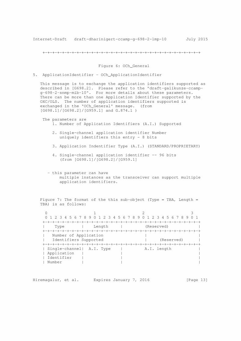
5. ApplicationIdentifier - OCh_ApplicationIdentifier
This message is to exchange the application identifiers supported as described in [G698.2]. Please refer to the "draft-galikunze-ccamp- g-698-2-snmp-mib-10". For more details about these parameters. There can be more than one Application Identifier supported by the OXC/OLS. The number of application identifiers supported is exchanged in the "OCh_General" message. (from [G698.1]/[G698.2]/[G959.1] and G.874.1 )
The parameters are 1. Number of Application Identifiers (A.I.) Supported
2. Single-channel application identifier Number uniquely identifiers this entry - 8 bits
3. Application Indentifier Type (A.I.) (STANDARD/PROPRIETARY)
4. Single-channel application identifier -- 96 bits (from [G698.1]/[G698.2]/[G959.1]
- this parameter can have multiple instances as the transceiver can support multiple application identifiers.
Figure 7: The format of the this sub-object (Type = TBA, Length = TBA) is as follows:
0 1 2 3 0 1 2 3 4 5 6 7 8 9 0 1 2 3 4 5 6 7 8 9 0 1 2 3 4 5 6 7 8 9 0 1 +-+-+-+-+-+-+-+-+-+-+-+-+-+-+-+-+-+-+-+-+-+-+-+-+-+-+-+-+-+-+-+-+ | Type | Length | (Reserved) | +-+-+-+-+-+-+-+-+-+-+-+-+-+-+-+-+-+-+-+-+-+-+-+-+-+-+-+-+-+-+-+-+ | Number of Application | | | Identifiers Supported | (Reserved) | +-+-+-+-+-+-+-+-+-+-+-+-+-+-+-+-+-+-+-+-+-+-+-+-+-+-+-+-+-+-+-+-+ | Single-channel| A.I. Type | A.I. length | | Application | | | | Identifier | | | | Number | | |
Hiremagalur, et al. Expires January 7, 2016 [Page 13]
Internet-Draft draft-dharinigert-ccamp-g-698-2-lmp-10 July 2015
+-+-+-+-+-+-+-+-+-+-+-+-+-+-+-+-+-+-+-+-+-+-+-+-+-+-+-+-+-+-+-+-+ | Single-channel Application Identifier | +-+-+-+-+-+-+-+-+-+-+-+-+-+-+-+-+-+-+-+-+-+-+-+-+-+-+-+-+-+-+-+-+ | Single-channel Application Identifier | +-+-+-+-+-+-+-+-+-+-+-+-+-+-+-+-+-+-+-+-+-+-+-+-+-+-+-+-+-+-+-+-+ | Single-channel Application Identifier | +-+-+-+-+-+-+-+-+-+-+-+-+-+-+-+-+-+-+-+-+-+-+-+-+-+-+-+-+-+-+-+-+ // .... // +-+-+-+-+-+-+-+-+-+-+-+-+-+-+-+-+-+-+-+-+-+-+-+-+-+-+-+-+-+-+-+-+ | Single-channel| | A.I. length | | Application | A.I. Type | | | Identifier | | | | Number | | | | | | | +-+-+-+-+-+-+-+-+-+-+-+-+-+-+-+-+-+-+-+-+-+-+-+-+-+-+-+-+-+-+-+-+ | Single-channel Application Identifier | +-+-+-+-+-+-+-+-+-+-+-+-+-+-+-+-+-+-+-+-+-+-+-+-+-+-+-+-+-+-+-+-+ | Single-channel Application Identifier | +-+-+-+-+-+-+-+-+-+-+-+-+-+-+-+-+-+-+-+-+-+-+-+-+-+-+-+-+-+-+-+-+ | Single-channel Application Identifier | +-+-+-+-+-+-+-+-+-+-+-+-+-+-+-+-+-+-+-+-+-+-+-+-+-+-+-+-+-+-+-+-+
A.I. Type in use: STANDARD, PROPRIETARY
A.I. Type in use: STANDARD Refer to G.698.2 recommendation : B-DScW-ytz(v)
0 1 2 3 0 1 2 3 4 5 6 7 8 9 0 1 2 3 4 5 6 7 8 9 0 1 2 3 4 5 6 7 8 9 0 1 +-+-+-+-+-+-+-+-+-+-+-+-+-+-+-+-+-+-+-+-+-+-+-+-+-+-+-+-+-+-+-+-+ | Single-channel Application Code | +-+-+-+-+-+-+-+-+-+-+-+-+-+-+-+-+-+-+-+-+-+-+-+-+-+-+-+-+-+-+-+-+ | Single-channel Application Code | +-+-+-+-+-+-+-+-+-+-+-+-+-+-+-+-+-+-+-+-+-+-+-+-+-+-+-+-+-+-+-+-+ | Single-channel Application Code | +-+-+-+-+-+-+-+-+-+-+-+-+-+-+-+-+-+-+-+-+-+-+-+-+-+-+-+-+-+-+-+-+
A.I. Type in use: PROPRIETARY
Note: if the A.I. type = PROPRIETARY, the first 6 Octets of the Application Identifier in use are six characters of the PrintableString must contain the Hexadecimal representation of an OUI (Organizationally Unique Identifier) assigned to the vendor whose implementation generated the Application Identifier; the remaining octets of the PrintableString are unspecified.
Hiremagalur, et al. Expires January 7, 2016 [Page 14]
Internet-Draft draft-dharinigert-ccamp-g-698-2-lmp-10 July 2015
0 1 2 3 0 1 2 3 4 5 6 7 8 9 0 1 2 3 4 5 6 7 8 9 0 1 2 3 4 5 6 7 8 9 0 1 +-+-+-+-+-+-+-+-+-+-+-+-+-+-+-+-+-+-+-+-+-+-+-+-+-+-+-+-+-+-+-+-+ | OUI | +-+-+-+-+-+-+-+-+-+-+-+-+-+-+-+-+-+-+-+-+-+-+-+-+-+-+-+-+-+-+-+-+ | OUI cont. | Vendor value | +-+-+-+-+-+-+-+-+-+-+-+-+-+-+-+-+-+-+-+-+-+-+-+-+-+-+-+-+-+-+-+-+ | Vendor Value | +-+-+-+-+-+-+-+-+-+-+-+-+-+-+-+-+-+-+-+-+-+-+-+-+-+-+-+-+-+-+-+-+
Figure 7: OCh_ApplicationIdentifier
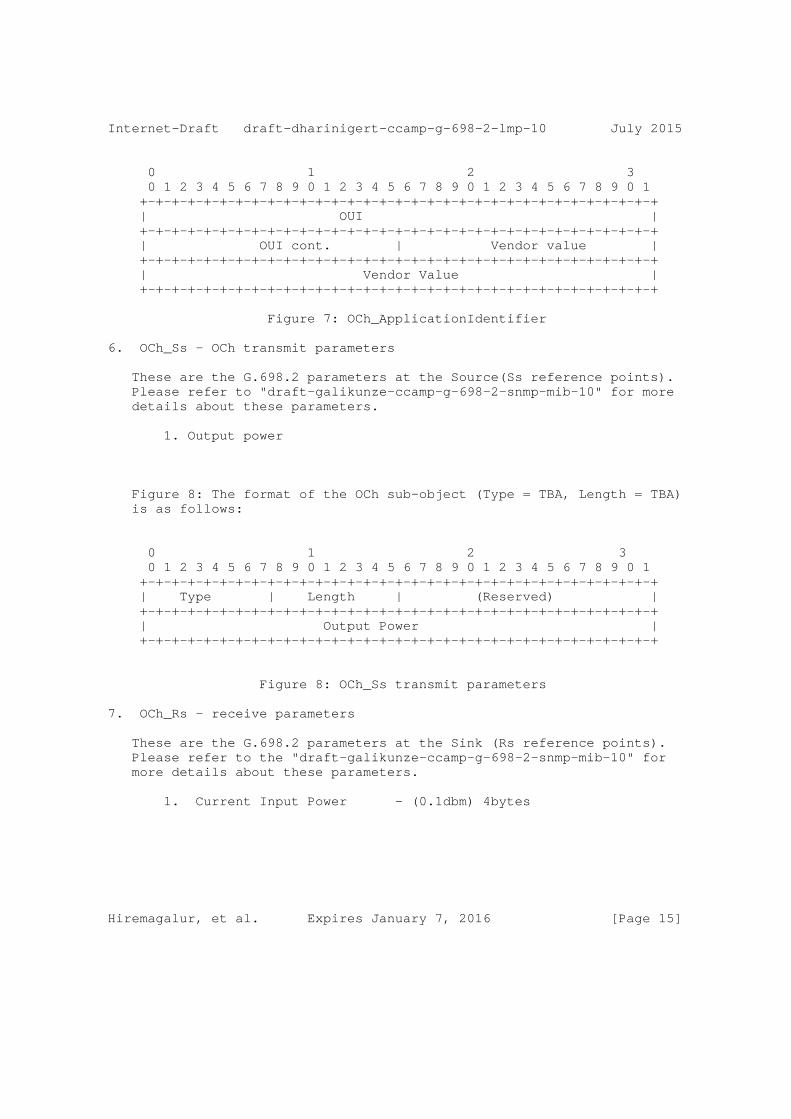
6. OCh_Ss - OCh transmit parameters
These are the G.698.2 parameters at the Source(Ss reference points). Please refer to "draft-galikunze-ccamp-g-698-2-snmp-mib-10" for more details about these parameters.
1. Output power
Figure 8: The format of the OCh sub-object (Type = TBA, Length = TBA) is as follows:
0 1 2 3 0 1 2 3 4 5 6 7 8 9 0 1 2 3 4 5 6 7 8 9 0 1 2 3 4 5 6 7 8 9 0 1 +-+-+-+-+-+-+-+-+-+-+-+-+-+-+-+-+-+-+-+-+-+-+-+-+-+-+-+-+-+-+-+-+ | Type | Length | (Reserved) | +-+-+-+-+-+-+-+-+-+-+-+-+-+-+-+-+-+-+-+-+-+-+-+-+-+-+-+-+-+-+-+-+ | Output Power | +-+-+-+-+-+-+-+-+-+-+-+-+-+-+-+-+-+-+-+-+-+-+-+-+-+-+-+-+-+-+-+-+
Figure 8: OCh_Ss transmit parameters
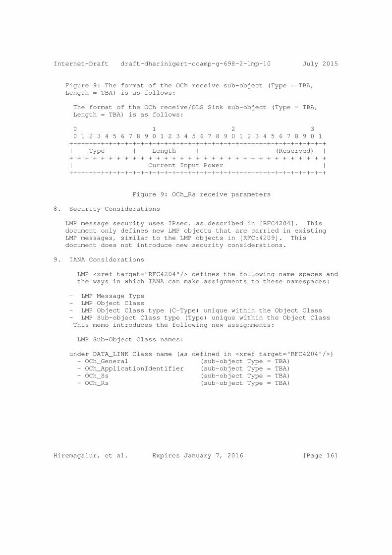
7. OCh_Rs - receive parameters
These are the G.698.2 parameters at the Sink (Rs reference points). Please refer to the "draft-galikunze-ccamp-g-698-2-snmp-mib-10" for more details about these parameters.
1. Current Input Power - (0.1dbm) 4bytes
Hiremagalur, et al. Expires January 7, 2016 [Page 15]
Internet-Draft draft-dharinigert-ccamp-g-698-2-lmp-10 July 2015
Figure 9: The format of the OCh receive sub-object (Type = TBA, Length = TBA) is as follows:
The format of the OCh receive/OLS Sink sub-object (Type = TBA, Length = TBA) is as follows:
0 1 2 3 0 1 2 3 4 5 6 7 8 9 0 1 2 3 4 5 6 7 8 9 0 1 2 3 4 5 6 7 8 9 0 1 +-+-+-+-+-+-+-+-+-+-+-+-+-+-+-+-+-+-+-+-+-+-+-+-+-+-+-+-+-+-+-+-+ | Type | Length | (Reserved) | +-+-+-+-+-+-+-+-+-+-+-+-+-+-+-+-+-+-+-+-+-+-+-+-+-+-+-+-+-+-+-+-+ | Current Input Power | +-+-+-+-+-+-+-+-+-+-+-+-+-+-+-+-+-+-+-+-+-+-+-+-+-+-+-+-+-+-+-+-+
Figure 9: OCh_Rs receive parameters
8. Security Considerations
LMP message security uses IPsec, as described in [RFC4204]. This document only defines new LMP objects that are carried in existing LMP messages, similar to the LMP objects in [RFC:4209]. This document does not introduce new security considerations.
9. IANA Considerations
LMP <xref target="RFC4204"/> defines the following name spaces and the ways in which IANA can make assignments to these namespaces:
- LMP Message Type - LMP Object Class - LMP Object Class type (C-Type) unique within the Object Class - LMP Sub-object Class type (Type) unique within the Object Class This memo introduces the following new assignments:
LMP Sub-Object Class names:
under DATA_LINK Class name (as defined in <xref target="RFC4204"/>) - OCh_General (sub-object Type = TBA) - OCh_ApplicationIdentifier (sub-object Type = TBA) - OCh_Ss (sub-object Type = TBA) - OCh_Rs (sub-object Type = TBA)
Hiremagalur, et al. Expires January 7, 2016 [Page 16]
Internet-Draft draft-dharinigert-ccamp-g-698-2-lmp-10 July 2015
10. Contributors
Arnold Mattheus Deutsche Telekom Darmstadt Germany email [email protected]
John E. Drake Juniper 1194 N Mathilda Avenue HW-US,Pennsylvania USA [email protected]
11. References
11.1. Normative References
[RFC4204] Lang, J., "Link Management Protocol (LMP)", RFC 4204, October 2005.
[RFC4209] Fredette, A. and J. Lang, "Link Management Protocol (LMP) for Dense Wavelength Division Multiplexing (DWDM) Optical Line Systems", RFC 4209, October 2005.
[RFC6205] Otani, T. and D. Li, "Generalized Labels for Lambda- Switch-Capable (LSC) Label Switching Routers", RFC 6205, March 2011.
[RFC4054] Strand, J. and A. Chiu, "Impairments and Other Constraints on Optical Layer Routing", RFC 4054, May 2005.
[ITU.G698.2] International Telecommunications Union, "Amplified multichannel dense wavelength division multiplexing applications with single channel optical interfaces", ITU-T Recommendation G.698.2, November 2009.
[ITU.G694.1] International Telecommunications Union, ""Spectral grids for WDM applications: DWDM frequency grid"", ITU-T Recommendation G.698.2, February 2012.
Hiremagalur, et al. Expires January 7, 2016 [Page 17]
Internet-Draft draft-dharinigert-ccamp-g-698-2-lmp-10 July 2015
[ITU.G709] International Telecommunications Union, "Interface for the Optical Transport Network (OTN)", ITU-T Recommendation G.709, February 2012.
[ITU.G872] International Telecommunications Union, "Architecture of optical transport networks", ITU-T Recommendation G.872, October 2012.
[ITU.G874.1] International Telecommunications Union, "Optical transport network (OTN): Protocol-neutral management information model for the network element view", ITU-T Recommendation G.874.1, October 2012.
11.2. Informative References
[RFC3410] Case, J., Mundy, R., Partain, D., and B. Stewart, "Introduction and Applicability Statements for Internet- Standard Management Framework", RFC 3410, December 2002.
[RFC2629] Rose, M., "Writing I-Ds and RFCs using XML", RFC 2629, June 1999.
[RFC4181] Heard, C., "Guidelines for Authors and Reviewers of MIB Documents", BCP 111, RFC 4181, September 2005.
[I-D.kunze-g-698-2-management-control-framework] Kunze, R., "A framework for Management and Control of optical interfaces supporting G.698.2", draft-kunze- g-698-2-management-control-framework-00 (work in progress), July 2011.
Authors’ Addresses
Dharini Hiremagalur (editor) Juniper 1194 N Mathilda Avenue Sunnyvale - 94089 California USA
Phone: +1408 Email: [email protected]
Hiremagalur, et al. Expires January 7, 2016 [Page 18]
Internet-Draft draft-dharinigert-ccamp-g-698-2-lmp-10 July 2015
Gert Grammel (editor) Juniper Oskar-Schlemmer Str. 15 80807 Muenchen Germany
Phone: +49 1725186386 Email: [email protected]
Gabriele Galimberti (editor) Cisco Via S. Maria Molgora, 48 20871 - Vimercate Italy
Phone: +390392091462 Email: [email protected]
Zafar Ali (editor) Cisco 3000 Innovation Drive KANATA ONTARIO K2K 3E8
Email: [email protected]
Ruediger Kunze (editor) Deutsche Telekom Dddd, xx Berlin Germany
Phone: +49xxxxxxxxxx Email: [email protected]
Dieter Beller (editor) ALU Lorenzstrasse, 10 70435 Stuttgart Germany
Phone: +4971182143125 Email: [email protected]
Hiremagalur, et al. Expires January 7, 2016 [Page 19]

Internet Engineering Task Force G.Galimberti, Ed.Internet-Draft CiscoIntended status: Standards Track R.Kunze, Ed.Expires: January 7, 2016 Deutsche Telekom Kam Lam, Ed. Alcatel-Lucent D. Hiremagalur, Ed. Juniper L.Fang, Ed. G.Ratterree, Ed. Microsoft July 6, 2015
An SNMP MIB extension to RFC3591 to manage optical interface parameters of "G.698.2 single channel" in DWDM applications draft-galikunze-ccamp-g-698-2-snmp-mib-12
Abstract
This memo defines a module of the Management Information Base (MIB) used by Simple Network Management Protocol (SNMP) in TCP/IP- based internet. In particular, it defines objects for managing single channel optical interface parameters of DWDM applications, using the approach specified in G.698.2 [ITU.G698.2] . This interface, described in ITU-T G.872, G.709 and G.798, is one type of OTN multi- vendor Intra-Domain Interface (IaDI). This RFC is an extension of RFC3591 to support the optical parameters specified in ITU-T G.698.2 and application identifiers specified in ITU-T G.874.1 [ITU.G874.1]. Note that G.874.1 encompasses vendor-specific codes, which if used would make the interface a single vendor IaDI and could still be managed.
The MIB module defined in this memo can be used for Optical Parameters monitoring and/or configuration of the endpoints of the multi-vendor IaDI based on the Black Link approach.
Copyright Notice
Copyright (c) 2015 IETF Trust and the persons identified as the document authors. All rights reserved.
Status of This Memo
This Internet-Draft is submitted in full conformance with the provisions of BCP 78 and BCP 79.
G.Galimberti, et al. Expires January 7, 2016 [Page 1]
Internet-Draft draft-galikunze-ccamp-g-698-2-snmp-mib-12 July 2015
Internet-Drafts are working documents of the Internet Engineering Task Force (IETF). Note that other groups may also distribute working documents as Internet-Drafts. The list of current Internet- Drafts is at http://datatracker.ietf.org/drafts/current/.
Internet-Drafts are draft documents valid for a maximum of six months and may be updated, replaced, or obsoleted by other documents at any time. It is inappropriate to use Internet-Drafts as reference material or to cite them other than as "work in progress."
This Internet-Draft will expire on January 7, 2016.
Copyright Notice
Copyright (c) 2015 IETF Trust and the persons identified as the document authors. All rights reserved.
This document is subject to BCP 78 and the IETF Trust’s Legal Provisions Relating to IETF Documents (http://trustee.ietf.org/license-info) in effect on the date of publication of this document. Please review these documents carefully, as they describe your rights and restrictions with respect to this document. Code Components extracted from this document must include Simplified BSD License text as described in Section 4.e of the Trust Legal Provisions and are provided without warranty as described in the Simplified BSD License.
Table of Contents
1. Introduction . . . . . . . . . . . . . . . . . . . . . . . . 3 2. The Internet-Standard Management Framework . . . . . . . . . 4 3. Conventions . . . . . . . . . . . . . . . . . . . . . . . . . 5 4. Overview . . . . . . . . . . . . . . . . . . . . . . . . . . 5 4.1. Use Cases . . . . . . . . . . . . . . . . . . . . . . . . 6 4.2. Optical Parameters Description . . . . . . . . . . . . . 13 4.2.1. Rs-Ss Configuration . . . . . . . . . . . . . . . . . 13 4.2.2. Table of Application Identifiers . . . . . . . . . . 14 4.3. Use of ifTable . . . . . . . . . . . . . . . . . . . . . 15 4.3.1. Use of ifTable for OPS Layer . . . . . . . . . . . . 16 4.3.2. Use of ifTable for OCh Layer . . . . . . . . . . . . 17 4.3.3. Use of ifStackTable . . . . . . . . . . . . . . . . . 17 5. Structure of the MIB Module . . . . . . . . . . . . . . . . . 18 6. Object Definitions . . . . . . . . . . . . . . . . . . . . . 18 7. Relationship to Other MIB Modules . . . . . . . . . . . . . . 25 7.1. Relationship to the [TEMPLATE TODO] MIB . . . . . . . . . 25 7.2. MIB modules required for IMPORTS . . . . . . . . . . . . 25 8. Definitions . . . . . . . . . . . . . . . . . . . . . . . . . 25 9. Security Considerations . . . . . . . . . . . . . . . . . . . 25
G.Galimberti, et al. Expires January 7, 2016 [Page 2]

Internet-Draft draft-galikunze-ccamp-g-698-2-snmp-mib-12 July 2015
10. IANA Considerations . . . . . . . . . . . . . . . . . . . . . 26 11. Contributors . . . . . . . . . . . . . . . . . . . . . . . . 26 12. References . . . . . . . . . . . . . . . . . . . . . . . . . 27 12.1. Normative References . . . . . . . . . . . . . . . . . . 27 12.2. Informative References . . . . . . . . . . . . . . . . . 29 Appendix A. Change Log . . . . . . . . . . . . . . . . . . . . . 30 Appendix B. Open Issues . . . . . . . . . . . . . . . . . . . . 30 Authors’ Addresses . . . . . . . . . . . . . . . . . . . . . . . 30
1. Introduction
This memo defines a portion of the Management Information Base (MIB) used by Simple Network Management Protocol (SNMP)in TCP/IP-based internets. In particular, it defines objects for managing single channel optical interface parameters of DWDM applications, using the approach specified in G.698.2. This RFC is an extension of RFC3591 to support the optical parameters specified in ITU-T G.698.2 [ITU.G698.2] and application identifiers specified in ITU-T G.874.1 [ITU.G874.1] . Note that G.874.1 encompasses vendor-specific codes, which if used would make the interface a single vendor IaDI and could still be managed.
The Black Link approach allows supporting an optical transmitter/ receiver pair of one vendor to inject an optical tributary signal and run it over an optical network composed of amplifiers, filters, add- drop multiplexers from a different vendor. In the OTN architecture, the ’black-link’ represents a pre-certified network media channel conforming to G.698.2 specifications at the S and R reference points.
[Editor’s note: In G.698.2 this corresponds to the optical path from point S to R; network media channel is also used and explained in draft-ietf-ccamp-flexi-grid-fwk-02]
Management will be performed at the edges of the network media channel (i.e., at the transmitters and receivers attached to the S and R reference points respectively) for the relevant parameters specified in G.698.2 [ITU.G698.2], G.798 [ITU.G798], G.874 [ITU.G874], and the performance parameters specified in G.7710/Y.1701 [ITU-T G.7710] and G.874.1 [ITU.G874.1].
G.698.2 [ITU.G698.2] is primarily intended for metro applications that include optical amplifiers. Applications are defined in G.698.2 [ITU.G698.2] using optical interface parameters at the single-channel connection points between optical transmitters and the optical multiplexer, as well as between optical receivers and the optical demultiplexer in the DWDM system. This Recommendation uses a methodology which does not explicitly specify the details of the optical network between reference point Ss and Rs, e.g., the passive
G.Galimberti, et al. Expires January 7, 2016 [Page 3]
Internet-Draft draft-galikunze-ccamp-g-698-2-snmp-mib-12 July 2015
and active elements or details of the design. The Recommendation currently includes unidirectional DWDM applications at 2.5 and 10 Gbit/s (with 100 GHz and 50 GHz channel frequency spacing). Work is still under way for 40 and 100 Gbit/s interfaces. There is possibility for extensions to a lower channel frequency spacing. This document specifically refers to the "application code" defined in the G.698.2 [ITU.G698.2] and included in the Application Identifier defined in G.874.1 [ITU.G874.1] and G.872 [ITU.G872], plus a few optical parameters not included in the G.698.2 application code specification.
This draft refers and supports also the draft-kunze-g-698-2- management-control-framework
The building of an SNMP MIB describing the optical parameters defined in G.698.2 [ITU.G698.2], and reflected in G.874.1 [ITU.G874], allows the different vendors and operator to retrieve, provision and exchange information across the G.698.2 multi-vendor IaDI in a standardized way.
The MIB, reporting the Optical parameters and their values, characterizes the features and the performances of the optical components and allow a reliable black link design in case of multi vendor optical networks.
Although RFC 3591 [RFC3591] describes and defines the SNMP MIB of a number of key optical parameters, alarms and Performance Monitoring, as this RFC is over a decade old, it is primarily pre-OTN, and a more complete and up-to-date description of optical parameters and processes can be found in the relevant ITU-T Recommendations. The same considerations can be applied to the RFC 4054 [RFC4054]
2. The Internet-Standard Management Framework
For a detailed overview of the documents that describe the current Internet-Standard Management Framework, please refer to section 7 of RFC 3410 [RFC3410].
Managed objects are accessed via a virtual information store, termed the Management Information Base or MIB. MIB objects are generally accessed through the Simple Network Management Protocol (SNMP). Objects in the MIB are defined using the mechanisms defined in the Structure of Management Information (SMI). This memo specifies a MIB module that is compliant to the SMIv2, which is described in STD 58, RFC 2578 [RFC2578], STD 58, RFC 2579 [RFC2579] and STD 58, RFC 2580 [RFC2580].
G.Galimberti, et al. Expires January 7, 2016 [Page 4]
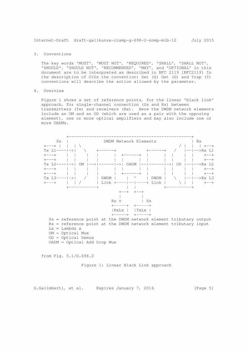
Internet-Draft draft-galikunze-ccamp-g-698-2-snmp-mib-12 July 2015
3. Conventions
The key words "MUST", "MUST NOT", "REQUIRED", "SHALL", "SHALL NOT", "SHOULD", "SHOULD NOT", "RECOMMENDED", "MAY", and "OPTIONAL" in this document are to be interpreted as described in RFC 2119 [RFC2119] In the description of OIDs the convention: Set (S) Get (G) and Trap (T) conventions will describe the action allowed by the parameter.
4. Overview
Figure 1 shows a set of reference points, for the linear "black link" approach, for single-channel connection (Ss and Rs) between transmitters (Tx) and receivers (Rx). Here the DWDM network elements include an OM and an OD (which are used as a pair with the opposing element), one or more optical amplifiers and may also include one or more OADMs.
+-------------------------------------------------+ Ss | DWDM Network Elements | Rs +---+ | | | \ / | | | +--+ Tx L1----|->| \ +------+ +------+ / |--|-->Rx L1 +---+ | | | | | +------+ | | | | | +--+ +---+ | | | | | | | | | | | | +--+ Tx L2----|->| OM |-->|------|->| OADM |--|------|->| OD |--|-->Rx L2 +---+ | | | | | | | | | | | | +--+ +---+ | | | | | +------+ | | | | | +--+ Tx L3----|->| / | DWDM | | ^ | DWDM | \ |--|-->Rx L3 +---+ | | / | Link +----|--|----+ Link | \ | | +--+ +-----------+ | | +----------+ +--+ +--+ | | Rs v | Ss +-----+ +-----+ |RxLx | |TxLx | +-----+ +-----+ Ss = reference point at the DWDM network element tributary output Rs = reference point at the DWDM network element tributary input Lx = Lambda x OM = Optical Mux OD = Optical Demux OADM = Optical Add Drop Mux
from Fig. 5.1/G.698.2
Figure 1: Linear Black Link approach
G.Galimberti, et al. Expires January 7, 2016 [Page 5]

Internet-Draft draft-galikunze-ccamp-g-698-2-snmp-mib-12 July 2015
G.698.2 [ITU.G698.2] defines also Ring "Black Link" approach configurations [Fig. 5.2/G.698.2] and Linear "black link" approach for Bidirectional applications[Fig. 5.3/G.698.2]
4.1. Use Cases
The use cases described below are assuming that power monitoring functions are available in the ingress and egress network element of the DWDM network, respectively. By performing link property correlation it would be beneficial to include the current transmit power value at reference point Ss and the current received power value at reference point Rs. For example if the Client transmitter power (OXC1) has a value of 0dBm and the ROADM interface measured power (at OLS1) is -6dBm the fiber patch cord connecting the two nodes may be pinched or the connectors are dirty. More, the interface characteristics can be used by the OLS network Control Plane in order to check the Optical Channels feasibility. Finally the OXC1 transceivers parameters (Application Code) can be shared with OXC2 using the LMP protocol to verify the Transceivers compatibility. The actual route selection of a specific wavelength within the allowed set is outside the scope of LMP. In GMPLS, the parameter selection (e.g. central frequency) is performed by RSVP-TE.
G.698.2 defines a single channel optical interface for DWDM systems that allows interconnecting network-external optical transponders across a DWDM network. The optical transponders are considered to be external to the DWDM network. This so-called ’black link’ approach illustrated in Figure 5-1 of G.698.2 and a copy of this figure is provided below. The single channel fiber link between the Ss/Rs reference points and the ingress/egress port of the network element on the domain boundary of the DWDM network (DWDM border NE) is called access link in this contribution. Based on the definition in G.698.2 it is considered to be part of the DWDM network. The access link typically is realized as a passive fiber link that has a specific optical attenuation (insertion loss). As the access link is an integral part of the DWDM network, it is desirable to monitor its attenuation. Therefore, it is useful to detect an increase of the access link attenuation, for example, when the access link fiber has been disconnected and reconnected (maintenance) and a bad patch panel connection (connector) resulted in a significantly higher access link attenuation (loss of signal in the extreme case of an open connector or a fiber cut). In the following section, two use cases are presented and discussed:
1) pure access link monitoring 2) access link monitoring with a power control loop
G.Galimberti, et al. Expires January 7, 2016 [Page 6]

Internet-Draft draft-galikunze-ccamp-g-698-2-snmp-mib-12 July 2015
These use cases require a power monitor as described in G.697 (see section 6.1.2), that is capable to measure the optical power of the incoming or outgoing single channel signal. The use case where a power control loop is in place could even be used to compensate an increased attenuation as long as the optical transmitter can still be operated within its output power range defined by its application code.
G.Galimberti, et al. Expires January 7, 2016 [Page 7]
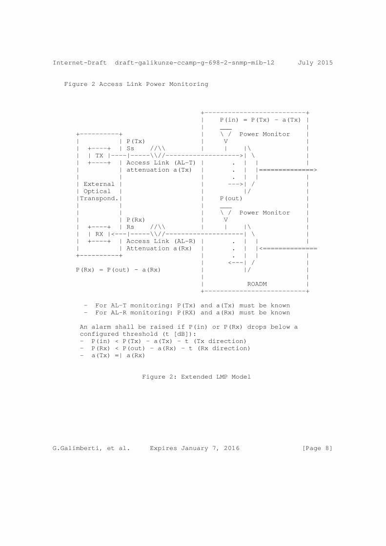
Internet-Draft draft-galikunze-ccamp-g-698-2-snmp-mib-12 July 2015
Figure 2 Access Link Power Monitoring
+--------------------------+ | P(in) = P(Tx) - a(Tx) | | ___ | +----------+ | \ / Power Monitor | | | P(Tx) | V | | +----+ | Ss //\\ | | |\ | | | TX |----|-----\\//------------------->| \ | | +----+ | Access Link (AL-T) | . | | | | | attenuation a(Tx) | . | |==============> | | | . | | | | External | | --->| / | | Optical | | |/ | |Transpond.| | P(out) | | | | ___ | | | | \ / Power Monitor | | | P(Rx) | V | | +----+ | Rs //\\ | | |\ | | | RX |<---|-----\\//--------------------| \ | | +----+ | Access Link (AL-R) | . | | | | | Attenuation a(Rx) | . | |<============== +----------+ | . | | | | <---| / | P(Rx) = P(out) - a(Rx) | |/ | | | | ROADM | +--------------------------+
- For AL-T monitoring: P(Tx) and a(Tx) must be known - For AL-R monitoring: P(RX) and a(Rx) must be known
An alarm shall be raised if P(in) or P(Rx) drops below a configured threshold (t [dB]): - P(in) < P(Tx) - a(Tx) - t (Tx direction) - P(Rx) < P(out) - a(Rx) - t (Rx direction) - a(Tx) =| a(Rx)
Figure 2: Extended LMP Model
G.Galimberti, et al. Expires January 7, 2016 [Page 8]
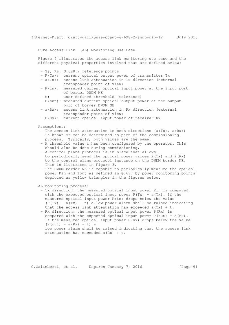
Internet-Draft draft-galikunze-ccamp-g-698-2-snmp-mib-12 July 2015
Pure Access Link (AL) Monitoring Use Case
Figure 4 illustrates the access link monitoring use case and the different physical properties involved that are defined below:
- Ss, Rs: G.698.2 reference points - P(Tx): current optical output power of transmitter Tx - a(Tx): access link attenuation in Tx direction (external transponder point of view) - P(in): measured current optical input power at the input port of border DWDM NE - t: user defined threshold (tolerance) - P(out): measured current optical output power at the output port of border DWDM NE - a(Rx): access link attenuation in Rx direction (external transponder point of view) - P(Rx): current optical input power of receiver Rx
Assumptions: - The access link attenuation in both directions (a(Tx), a(Rx)) is known or can be determined as part of the commissioning process. Typically, both values are the same. - A threshold value t has been configured by the operator. This should also be done during commissioning. - A control plane protocol is in place that allows to periodically send the optical power values P(Tx) and P(Rx) to the control plane protocol instance on the DWDM border NE. This is llustrated in Figure 3. - The DWDM border NE is capable to periodically measure the optical power Pin and Pout as defined in G.697 by power monitoring points depicted as yellow triangles in the figures below.
AL monitoring process: - Tx direction: the measured optical input power Pin is compared with the expected optical input power P(Tx) - a(Tx). If the measured optical input power P(in) drops below the value (P(Tx) - a(Tx) - t) a low power alarm shall be raised indicating that the access link attenuation has exceeded a(Tx) + t. - Rx direction: the measured optical input power P(Rx) is compared with the expected optical input power P(out) - a(Rx). If the measured optical input power P(Rx) drops below the value (P(out) - a(Rx) - t) a low power alarm shall be raised indicating that the access link attenuation has exceeded a(Rx) + t.
G.Galimberti, et al. Expires January 7, 2016 [Page 9]
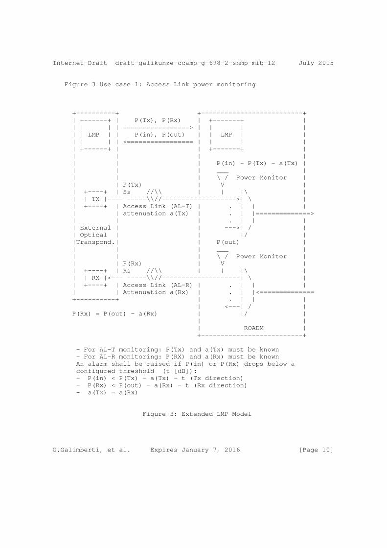
Internet-Draft draft-galikunze-ccamp-g-698-2-snmp-mib-12 July 2015
Figure 3 Use case 1: Access Link power monitoring
+----------+ +--------------------------+ | +------+ | P(Tx), P(Rx) | +-------+ | | | | | =================> | | | | | | LMP | | P(in), P(out) | | LMP | | | | | | <================= | | | | | +------+ | | +-------+ | | | | | | | | P(in) - P(Tx) - a(Tx) | | | | ___ | | | | \ / Power Monitor | | | P(Tx) | V | | +----+ | Ss //\\ | | |\ | | | TX |----|-----\\//------------------->| \ | | +----+ | Access Link (AL-T) | . | | | | | attenuation a(Tx) | . | |==============> | | | . | | | | External | | --->| / | | Optical | | |/ | |Transpond.| | P(out) | | | | ___ | | | | \ / Power Monitor | | | P(Rx) | V | | +----+ | Rs //\\ | | |\ | | | RX |<---|-----\\//--------------------| \ | | +----+ | Access Link (AL-R) | . | | | | | Attenuation a(Rx) | . | |<============== +----------+ | . | | | | <---| / | P(Rx) = P(out) - a(Rx) | |/ | | | | ROADM | +--------------------------+
- For AL-T monitoring: P(Tx) and a(Tx) must be known - For AL-R monitoring: P(RX) and a(Rx) must be known An alarm shall be raised if P(in) or P(Rx) drops below a configured threshold (t [dB]): - P(in) < P(Tx) - a(Tx) - t (Tx direction) - P(Rx) < P(out) - a(Rx) - t (Rx direction) - a(Tx) = a(Rx)
Figure 3: Extended LMP Model
G.Galimberti, et al. Expires January 7, 2016 [Page 10]

Internet-Draft draft-galikunze-ccamp-g-698-2-snmp-mib-12 July 2015
Power Control Loop Use Case
This use case is based on the access link monitoring use case as described above. In addition, the border NE is running a power control application that is capable to control the optical output power of the single channel tributary signal at the output port of the border DWDM NE (towards the external receiver Rx) and the optical output power of the single channel tributary signal at the external transmitter Tx within their known operating range. The time scale of this control loop is typically relatively slow (e.g. some 10s or minutes) because the access link attenuation is not expected to vary much over time (the attenuation only changes when re-cabling occurs). From a data plane perspective, this use case does not require additional data plane extensions. It does only require a protocol extension in the control plane (e.g. this LMP draft) that allows the power control application residing in the DWDM border NE to modify the optical output power of the DWDM domain-external transmitter Tx within the range of the currently used application code. Figure 5 below illustrates this use case utilizing the LMP protocol with extensions defined in this draft.
G.Galimberti, et al. Expires January 7, 2016 [Page 11]
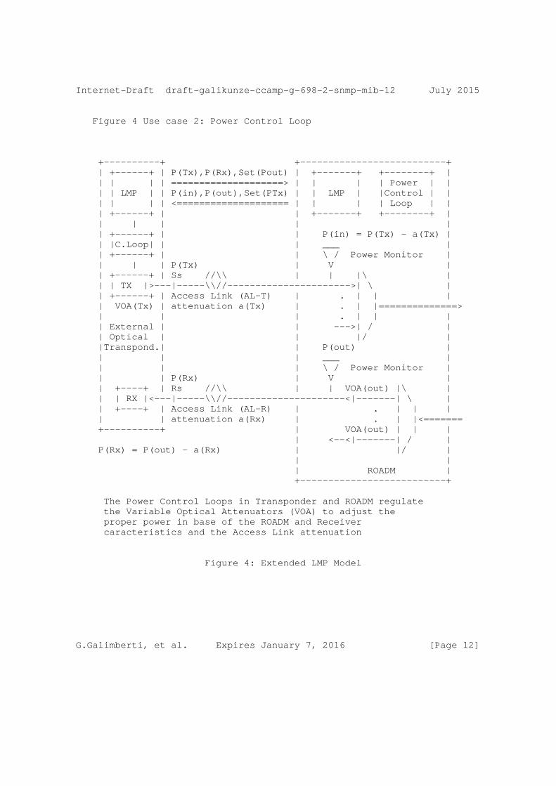
Internet-Draft draft-galikunze-ccamp-g-698-2-snmp-mib-12 July 2015
Figure 4 Use case 2: Power Control Loop
+----------+ +--------------------------+ | +------+ | P(Tx),P(Rx),Set(Pout) | +-------+ +--------+ | | | | | ====================> | | | | Power | | | | LMP | | P(in),P(out),Set(PTx) | | LMP | |Control | | | | | | <==================== | | | | Loop | | | +------+ | | +-------+ +--------+ | | | | | | | +------+ | | P(in) = P(Tx) - a(Tx) | | |C.Loop| | | ___ | | +------+ | | \ / Power Monitor | | | | P(Tx) | V | | +------+ | Ss //\\ | | |\ | | | TX |>---|-----\\//---------------------->| \ | | +------+ | Access Link (AL-T) | . | | | | VOA(Tx) | attenuation a(Tx) | . | |==============> | | | . | | | | External | | --->| / | | Optical | | |/ | |Transpond.| | P(out) | | | | ___ | | | | \ / Power Monitor | | | P(Rx) | V | | +----+ | Rs //\\ | | VOA(out) |\ | | | RX |<---|-----\\//---------------------<|-------| \ | | +----+ | Access Link (AL-R) | . | | | | | attenuation a(Rx) | . | |<======= +----------+ | VOA(out) | | | | <--<|-------| / | P(Rx) = P(out) - a(Rx) | |/ | | | | ROADM | +--------------------------+
The Power Control Loops in Transponder and ROADM regulate the Variable Optical Attenuators (VOA) to adjust the proper power in base of the ROADM and Receiver caracteristics and the Access Link attenuation
Figure 4: Extended LMP Model
G.Galimberti, et al. Expires January 7, 2016 [Page 12]
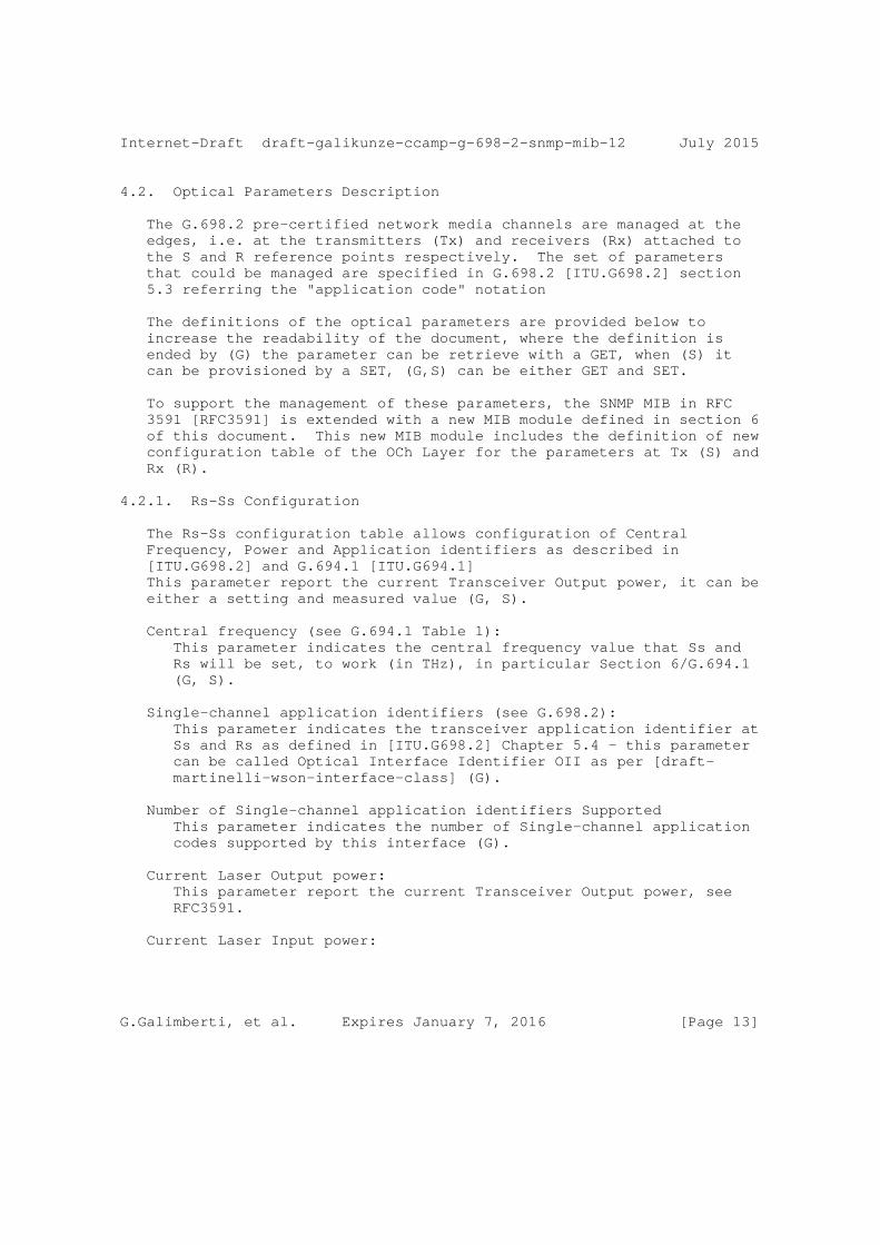
Internet-Draft draft-galikunze-ccamp-g-698-2-snmp-mib-12 July 2015
4.2. Optical Parameters Description
The G.698.2 pre-certified network media channels are managed at the edges, i.e. at the transmitters (Tx) and receivers (Rx) attached to the S and R reference points respectively. The set of parameters that could be managed are specified in G.698.2 [ITU.G698.2] section 5.3 referring the "application code" notation
The definitions of the optical parameters are provided below to increase the readability of the document, where the definition is ended by (G) the parameter can be retrieve with a GET, when (S) it can be provisioned by a SET, (G,S) can be either GET and SET.
To support the management of these parameters, the SNMP MIB in RFC 3591 [RFC3591] is extended with a new MIB module defined in section 6 of this document. This new MIB module includes the definition of new configuration table of the OCh Layer for the parameters at Tx (S) and Rx (R).
4.2.1. Rs-Ss Configuration
The Rs-Ss configuration table allows configuration of Central Frequency, Power and Application identifiers as described in [ITU.G698.2] and G.694.1 [ITU.G694.1] This parameter report the current Transceiver Output power, it can be either a setting and measured value (G, S).
Central frequency (see G.694.1 Table 1): This parameter indicates the central frequency value that Ss and Rs will be set, to work (in THz), in particular Section 6/G.694.1 (G, S).
Single-channel application identifiers (see G.698.2): This parameter indicates the transceiver application identifier at Ss and Rs as defined in [ITU.G698.2] Chapter 5.4 - this parameter can be called Optical Interface Identifier OII as per [draft- martinelli-wson-interface-class] (G).
Number of Single-channel application identifiers Supported This parameter indicates the number of Single-channel application codes supported by this interface (G).
Current Laser Output power: This parameter report the current Transceiver Output power, see RFC3591.
Current Laser Input power:
G.Galimberti, et al. Expires January 7, 2016 [Page 13]
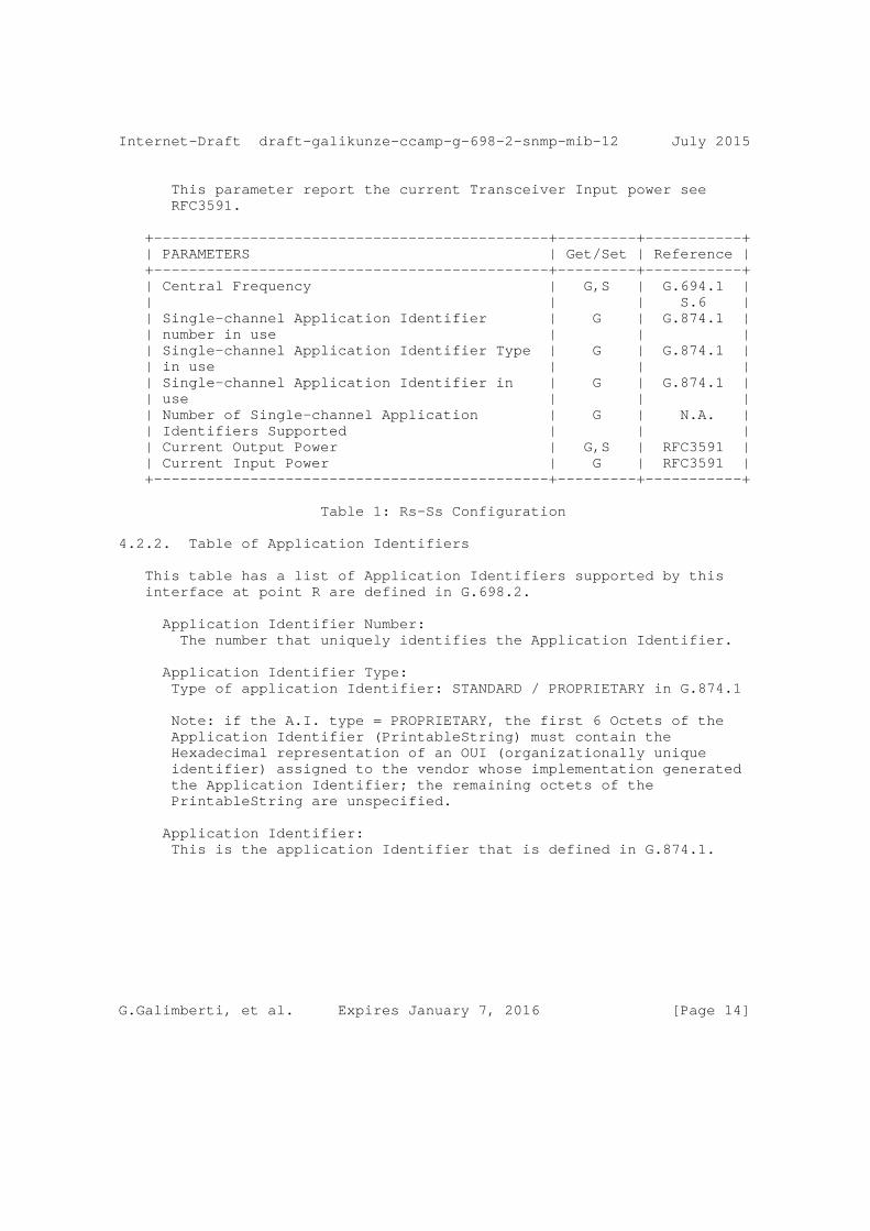
Internet-Draft draft-galikunze-ccamp-g-698-2-snmp-mib-12 July 2015
This parameter report the current Transceiver Input power see RFC3591.
+---------------------------------------------+---------+-----------+ | PARAMETERS | Get/Set | Reference | +---------------------------------------------+---------+-----------+ | Central Frequency | G,S | G.694.1 | | | | S.6 | | Single-channel Application Identifier | G | G.874.1 | | number in use | | | | Single-channel Application Identifier Type | G | G.874.1 | | in use | | | | Single-channel Application Identifier in | G | G.874.1 | | use | | | | Number of Single-channel Application | G | N.A. | | Identifiers Supported | | | | Current Output Power | G,S | RFC3591 | | Current Input Power | G | RFC3591 | +---------------------------------------------+---------+-----------+
Table 1: Rs-Ss Configuration
4.2.2. Table of Application Identifiers
This table has a list of Application Identifiers supported by this interface at point R are defined in G.698.2.
Application Identifier Number: The number that uniquely identifies the Application Identifier.
Application Identifier Type: Type of application Identifier: STANDARD / PROPRIETARY in G.874.1
Note: if the A.I. type = PROPRIETARY, the first 6 Octets of the Application Identifier (PrintableString) must contain the Hexadecimal representation of an OUI (organizationally unique identifier) assigned to the vendor whose implementation generated the Application Identifier; the remaining octets of the PrintableString are unspecified.
Application Identifier: This is the application Identifier that is defined in G.874.1.
G.Galimberti, et al. Expires January 7, 2016 [Page 14]
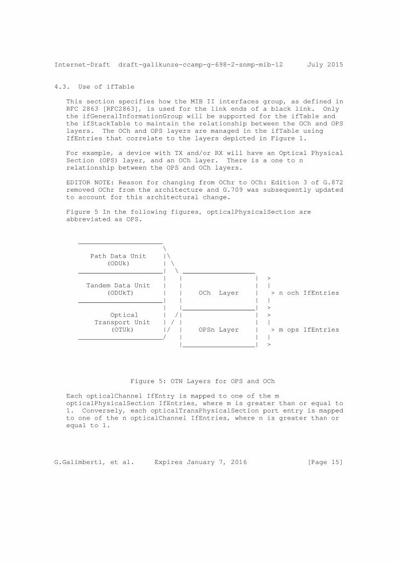
Internet-Draft draft-galikunze-ccamp-g-698-2-snmp-mib-12 July 2015
4.3. Use of ifTable
This section specifies how the MIB II interfaces group, as defined in RFC 2863 [RFC2863], is used for the link ends of a black link. Only the ifGeneralInformationGroup will be supported for the ifTable and the ifStackTable to maintain the relationship between the OCh and OPS layers. The OCh and OPS layers are managed in the ifTable using IfEntries that correlate to the layers depicted in Figure 1.
For example, a device with TX and/or RX will have an Optical Physical Section (OPS) layer, and an OCh layer. There is a one to n relationship between the OPS and OCh layers.
EDITOR NOTE: Reason for changing from OChr to OCh: Edition 3 of G.872 removed OChr from the architecture and G.709 was subsequently updated to account for this architectural change.
Figure 5 In the following figures, opticalPhysicalSection are abbreviated as OPS.
_____________________ \ Path Data Unit |\ (ODUk) | \ _____________________| \ __________________ | | | > Tandem Data Unit | | | | (ODUkT) | | OCh Layer | > n och IfEntries _____________________| | | | | |__________________| > Optical | /| | > Transport Unit | / | | | (OTUk) |/ | OPSn Layer | > m ops IfEntries _____________________/ | | | |__________________| >
Figure 5: OTN Layers for OPS and OCh
Each opticalChannel IfEntry is mapped to one of the m opticalPhysicalSection IfEntries, where m is greater than or equal to 1. Conversely, each opticalTransPhysicalSection port entry is mapped to one of the n opticalChannel IfEntries, where n is greater than or equal to 1.
G.Galimberti, et al. Expires January 7, 2016 [Page 15]
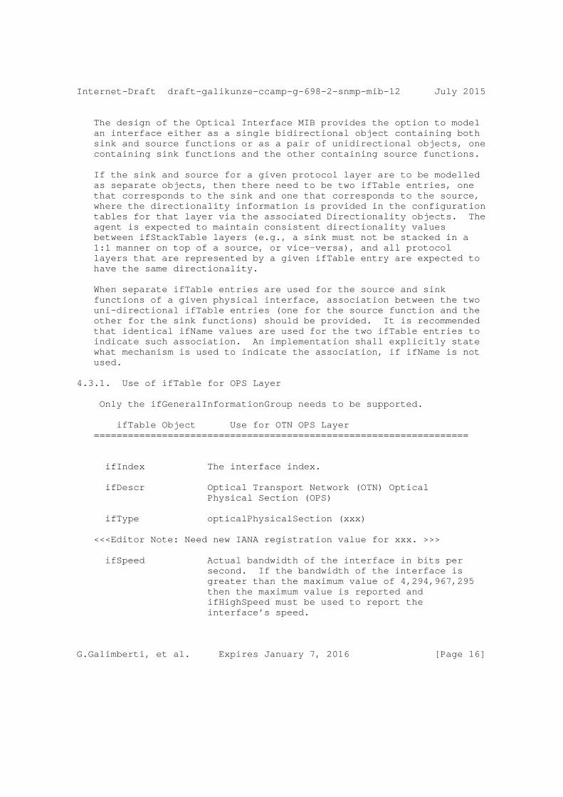
Internet-Draft draft-galikunze-ccamp-g-698-2-snmp-mib-12 July 2015
The design of the Optical Interface MIB provides the option to model an interface either as a single bidirectional object containing both sink and source functions or as a pair of unidirectional objects, one containing sink functions and the other containing source functions.
If the sink and source for a given protocol layer are to be modelled as separate objects, then there need to be two ifTable entries, one that corresponds to the sink and one that corresponds to the source, where the directionality information is provided in the configuration tables for that layer via the associated Directionality objects. The agent is expected to maintain consistent directionality values between ifStackTable layers (e.g., a sink must not be stacked in a 1:1 manner on top of a source, or vice-versa), and all protocol layers that are represented by a given ifTable entry are expected to have the same directionality.
When separate ifTable entries are used for the source and sink functions of a given physical interface, association between the two uni-directional ifTable entries (one for the source function and the other for the sink functions) should be provided. It is recommended that identical ifName values are used for the two ifTable entries to indicate such association. An implementation shall explicitly state what mechanism is used to indicate the association, if ifName is not used.
4.3.1. Use of ifTable for OPS Layer
Only the ifGeneralInformationGroup needs to be supported.
ifTable Object Use for OTN OPS Layer ==================================================================
ifIndex The interface index.
ifDescr Optical Transport Network (OTN) Optical Physical Section (OPS)
ifType opticalPhysicalSection (xxx)
<<<Editor Note: Need new IANA registration value for xxx. >>>
ifSpeed Actual bandwidth of the interface in bits per second. If the bandwidth of the interface is greater than the maximum value of 4,294,967,295 then the maximum value is reported and ifHighSpeed must be used to report the interface’s speed.
G.Galimberti, et al. Expires January 7, 2016 [Page 16]
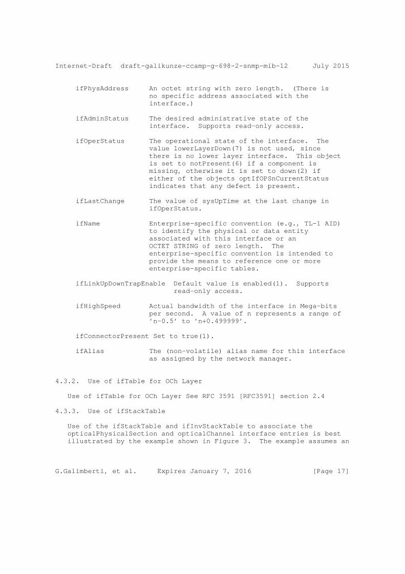
Internet-Draft draft-galikunze-ccamp-g-698-2-snmp-mib-12 July 2015
ifPhysAddress An octet string with zero length. (There is no specific address associated with the interface.)
ifAdminStatus The desired administrative state of the interface. Supports read-only access.
ifOperStatus The operational state of the interface. The value lowerLayerDown(7) is not used, since there is no lower layer interface. This object is set to notPresent(6) if a component is missing, otherwise it is set to down(2) if either of the objects optIfOPSnCurrentStatus indicates that any defect is present.
ifLastChange The value of sysUpTime at the last change in ifOperStatus.
ifName Enterprise-specific convention (e.g., TL-1 AID) to identify the physical or data entity associated with this interface or an OCTET STRING of zero length. The enterprise-specific convention is intended to provide the means to reference one or more enterprise-specific tables.
ifLinkUpDownTrapEnable Default value is enabled(1). Supports read-only access.
ifHighSpeed Actual bandwidth of the interface in Mega-bits per second. A value of n represents a range of ’n-0.5’ to ’n+0.499999’.
ifConnectorPresent Set to true(1).
ifAlias The (non-volatile) alias name for this interface as assigned by the network manager.
4.3.2. Use of ifTable for OCh Layer
Use of ifTable for OCh Layer See RFC 3591 [RFC3591] section 2.4
4.3.3. Use of ifStackTable
Use of the ifStackTable and ifInvStackTable to associate the opticalPhysicalSection and opticalChannel interface entries is best illustrated by the example shown in Figure 3. The example assumes an
G.Galimberti, et al. Expires January 7, 2016 [Page 17]
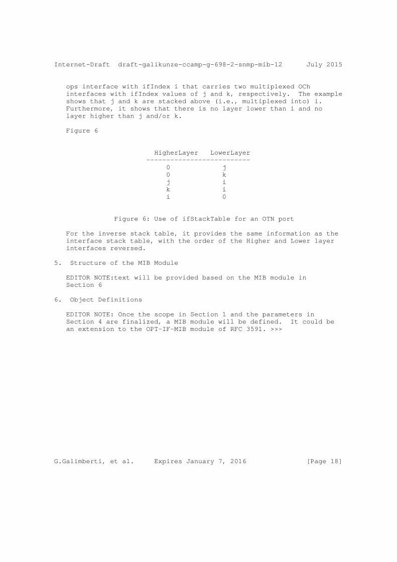
Internet-Draft draft-galikunze-ccamp-g-698-2-snmp-mib-12 July 2015
ops interface with ifIndex i that carries two multiplexed OCh interfaces with ifIndex values of j and k, respectively. The example shows that j and k are stacked above (i.e., multiplexed into) i. Furthermore, it shows that there is no layer lower than i and no layer higher than j and/or k.
Figure 6
HigherLayer LowerLayer -------------------------- 0 j 0 k j i k i i 0
Figure 6: Use of ifStackTable for an OTN port
For the inverse stack table, it provides the same information as the interface stack table, with the order of the Higher and Lower layer interfaces reversed.
5. Structure of the MIB Module
EDITOR NOTE:text will be provided based on the MIB module in Section 6
6. Object Definitions
EDITOR NOTE: Once the scope in Section 1 and the parameters in Section 4 are finalized, a MIB module will be defined. It could be an extension to the OPT-IF-MIB module of RFC 3591. >>>
G.Galimberti, et al. Expires January 7, 2016 [Page 18]
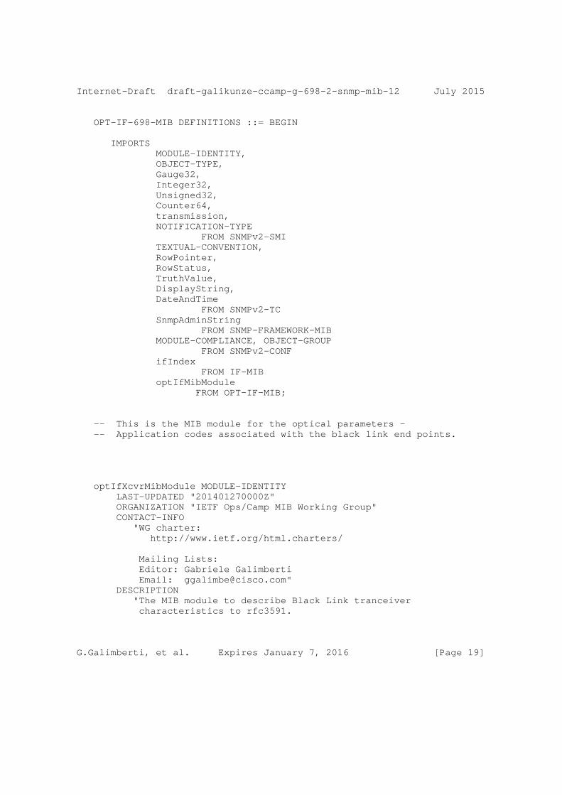
Internet-Draft draft-galikunze-ccamp-g-698-2-snmp-mib-12 July 2015
OPT-IF-698-MIB DEFINITIONS ::= BEGIN
IMPORTS MODULE-IDENTITY, OBJECT-TYPE, Gauge32, Integer32, Unsigned32, Counter64, transmission, NOTIFICATION-TYPE FROM SNMPv2-SMI TEXTUAL-CONVENTION, RowPointer, RowStatus, TruthValue, DisplayString, DateAndTime FROM SNMPv2-TC SnmpAdminString FROM SNMP-FRAMEWORK-MIB MODULE-COMPLIANCE, OBJECT-GROUP FROM SNMPv2-CONF ifIndex FROM IF-MIB optIfMibModule FROM OPT-IF-MIB;
-- This is the MIB module for the optical parameters - -- Application codes associated with the black link end points.
optIfXcvrMibModule MODULE-IDENTITY LAST-UPDATED "201401270000Z" ORGANIZATION "IETF Ops/Camp MIB Working Group" CONTACT-INFO "WG charter: http://www.ietf.org/html.charters/
Mailing Lists: Editor: Gabriele Galimberti Email: [email protected]" DESCRIPTION "The MIB module to describe Black Link tranceiver characteristics to rfc3591.
G.Galimberti, et al. Expires January 7, 2016 [Page 19]
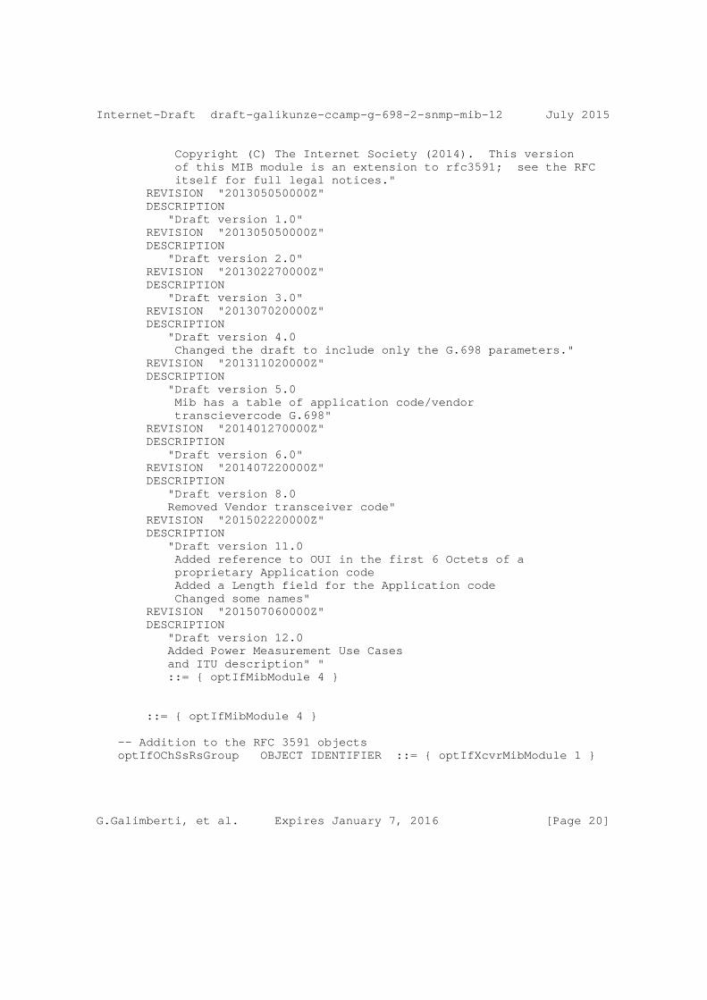
Internet-Draft draft-galikunze-ccamp-g-698-2-snmp-mib-12 July 2015
Copyright (C) The Internet Society (2014). This version of this MIB module is an extension to rfc3591; see the RFC itself for full legal notices." REVISION "201305050000Z" DESCRIPTION "Draft version 1.0" REVISION "201305050000Z" DESCRIPTION "Draft version 2.0" REVISION "201302270000Z" DESCRIPTION "Draft version 3.0" REVISION "201307020000Z" DESCRIPTION "Draft version 4.0 Changed the draft to include only the G.698 parameters." REVISION "201311020000Z" DESCRIPTION "Draft version 5.0 Mib has a table of application code/vendor transcievercode G.698" REVISION "201401270000Z" DESCRIPTION "Draft version 6.0" REVISION "201407220000Z" DESCRIPTION "Draft version 8.0 Removed Vendor transceiver code" REVISION "201502220000Z" DESCRIPTION "Draft version 11.0 Added reference to OUI in the first 6 Octets of a proprietary Application code Added a Length field for the Application code Changed some names" REVISION "201507060000Z" DESCRIPTION "Draft version 12.0 Added Power Measurement Use Cases and ITU description" " ::= { optIfMibModule 4 }
::= { optIfMibModule 4 }
-- Addition to the RFC 3591 objects optIfOChSsRsGroup OBJECT IDENTIFIER ::= { optIfXcvrMibModule 1 }
G.Galimberti, et al. Expires January 7, 2016 [Page 20]
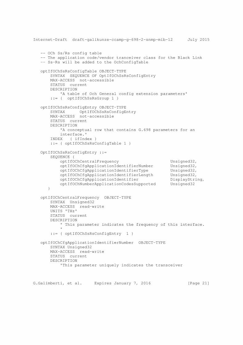
Internet-Draft draft-galikunze-ccamp-g-698-2-snmp-mib-12 July 2015
-- OCh Ss/Rs config table -- The application code/vendor tranceiver class for the Black Link -- Ss-Rs will be added to the OchConfigTable
optIfOChSsRsConfigTable OBJECT-TYPE SYNTAX SEQUENCE OF OptIfOChSsRsConfigEntry MAX-ACCESS not-accessible STATUS current DESCRIPTION "A table of Och General config extension parameters" ::= { optIfOChSsRsGroup 1 }
optIfOChSsRsConfigEntry OBJECT-TYPE SYNTAX OptIfOChSsRsConfigEntry MAX-ACCESS not-accessible STATUS current DESCRIPTION "A conceptual row that contains G.698 parameters for an interface." INDEX { ifIndex } ::= { optIfOChSsRsConfigTable 1 }
OptIfOChSsRsConfigEntry ::= SEQUENCE { optIfOChCentralFrequency Unsigned32, optIfOChCfgApplicationIdentifierNumber Unsigned32, optIfOChCfgApplicationIdentifierType Unsigned32, optIfOChCfgApplicationIdentifierLength Unsigned32, optIfOChCfgApplicationIdentifier DisplayString, optIfOChNumberApplicationCodesSupported Unsigned32 }
optIfOChCentralFrequency OBJECT-TYPE SYNTAX Unsigned32 MAX-ACCESS read-write UNITS "THz" STATUS current DESCRIPTION " This parameter indicates the frequency of this interface. " ::= { optIfOChSsRsConfigEntry 1 }
optIfOChCfgApplicationIdentifierNumber OBJECT-TYPE SYNTAX Unsigned32 MAX-ACCESS read-write STATUS current DESCRIPTION "This parameter uniquely indicates the transceiver
G.Galimberti, et al. Expires January 7, 2016 [Page 21]
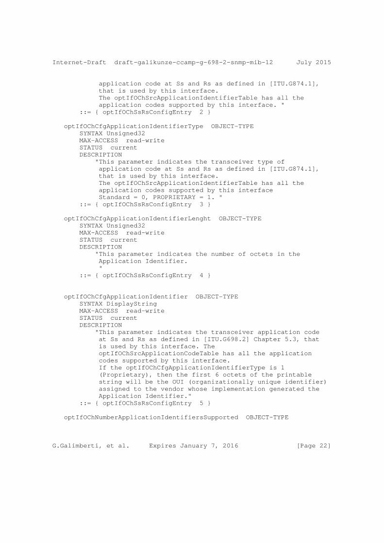
Internet-Draft draft-galikunze-ccamp-g-698-2-snmp-mib-12 July 2015
application code at Ss and Rs as defined in [ITU.G874.1], that is used by this interface. The optIfOChSrcApplicationIdentifierTable has all the application codes supported by this interface. " ::= { optIfOChSsRsConfigEntry 2 }
optIfOChCfgApplicationIdentifierType OBJECT-TYPE SYNTAX Unsigned32 MAX-ACCESS read-write STATUS current DESCRIPTION "This parameter indicates the transceiver type of application code at Ss and Rs as defined in [ITU.G874.1], that is used by this interface. The optIfOChSrcApplicationIdentifierTable has all the application codes supported by this interface Standard = 0, PROPRIETARY = 1. " ::= { optIfOChSsRsConfigEntry 3 }
optIfOChCfgApplicationIdentifierLenght OBJECT-TYPE SYNTAX Unsigned32 MAX-ACCESS read-write STATUS current DESCRIPTION "This parameter indicates the number of octets in the Application Identifier. " ::= { optIfOChSsRsConfigEntry 4 }
optIfOChCfgApplicationIdentifier OBJECT-TYPE SYNTAX DisplayString MAX-ACCESS read-write STATUS current DESCRIPTION "This parameter indicates the transceiver application code at Ss and Rs as defined in [ITU.G698.2] Chapter 5.3, that is used by this interface. The optIfOChSrcApplicationCodeTable has all the application codes supported by this interface. If the optIfOChCfgApplicationIdentifierType is 1 (Proprietary), then the first 6 octets of the printable string will be the OUI (organizationally unique identifier) assigned to the vendor whose implementation generated the Application Identifier." ::= { optIfOChSsRsConfigEntry 5 }
optIfOChNumberApplicationIdentifiersSupported OBJECT-TYPE
G.Galimberti, et al. Expires January 7, 2016 [Page 22]
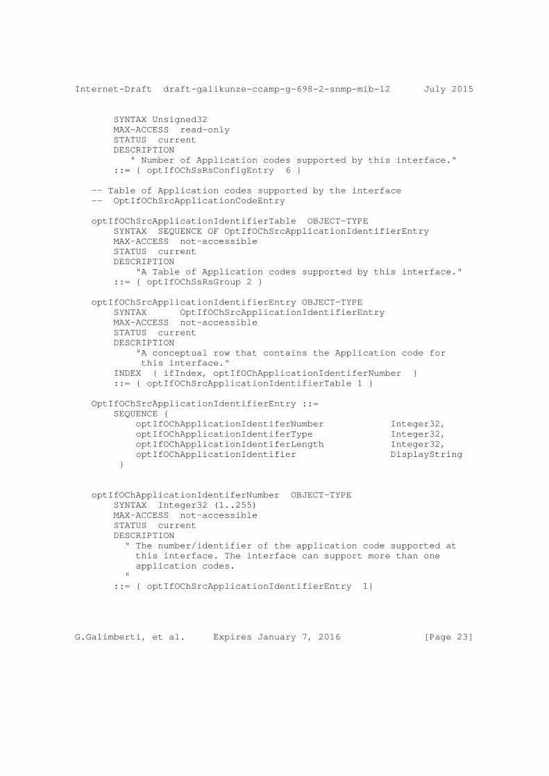
Internet-Draft draft-galikunze-ccamp-g-698-2-snmp-mib-12 July 2015
SYNTAX Unsigned32 MAX-ACCESS read-only STATUS current DESCRIPTION " Number of Application codes supported by this interface." ::= { optIfOChSsRsConfigEntry 6 }
-- Table of Application codes supported by the interface -- OptIfOChSrcApplicationCodeEntry
optIfOChSrcApplicationIdentifierTable OBJECT-TYPE SYNTAX SEQUENCE OF OptIfOChSrcApplicationIdentifierEntry MAX-ACCESS not-accessible STATUS current DESCRIPTION "A Table of Application codes supported by this interface." ::= { optIfOChSsRsGroup 2 }
optIfOChSrcApplicationIdentifierEntry OBJECT-TYPE SYNTAX OptIfOChSrcApplicationIdentifierEntry MAX-ACCESS not-accessible STATUS current DESCRIPTION "A conceptual row that contains the Application code for this interface." INDEX { ifIndex, optIfOChApplicationIdentiferNumber } ::= { optIfOChSrcApplicationIdentifierTable 1 }
OptIfOChSrcApplicationIdentifierEntry ::= SEQUENCE { optIfOChApplicationIdentiferNumber Integer32, optIfOChApplicationIdentiferType Integer32, optIfOChApplicationIdentiferLength Integer32, optIfOChApplicationIdentifier DisplayString }
optIfOChApplicationIdentiferNumber OBJECT-TYPE SYNTAX Integer32 (1..255) MAX-ACCESS not-accessible STATUS current DESCRIPTION " The number/identifier of the application code supported at this interface. The interface can support more than one application codes. " ::= { optIfOChSrcApplicationIdentifierEntry 1}
G.Galimberti, et al. Expires January 7, 2016 [Page 23]
Internet-Draft draft-galikunze-ccamp-g-698-2-snmp-mib-12 July 2015
optIfOChApplicationIdentiferType OBJECT-TYPE SYNTAX Integer32 (1..255) MAX-ACCESS read-only STATUS current DESCRIPTION " The type of identifier of the application code supported at this interface. The interface can support more than one application codes. Standard = 0, PROPRIETARY = 1 " ::= { optIfOChSrcApplicationIdentifierEntry 2}
optIfOChApplicationIdentiferLength OBJECT-TYPE SYNTAX Integer32 (1..255) MAX-ACCESS read-only STATUS current DESCRIPTION " This parameter indicates the number of octets in the Application Identifier. " ::= { optIfOChSrcApplicationIdentifierEntry 3}
optIfOChApplicationIdentifier OBJECT-TYPE SYNTAX DisplayString MAX-ACCESS read-only STATUS current DESCRIPTION " The application code supported by this interface DWDM link. If the optIfOChApplicationIdentiferType is 1 (Proprietary), then the first 6 octets of the printable string will be the OUI (organizationally unique identifier) assigned to the vendor whose implementation generated the Application Identifier." ::= { optIfOChSrcApplicationIdentifierEntry 4}
-- Notifications
-- Central Frequency Change Notification optIfOChCentralFrequencyChange NOTIFICATION-TYPE OBJECTS { optIfOChCentralFrequency } STATUS current DESCRIPTION "Notification of a change in the central frequency."
G.Galimberti, et al. Expires January 7, 2016 [Page 24]
Internet-Draft draft-galikunze-ccamp-g-698-2-snmp-mib-12 July 2015
::= { optIfXcvrMibModule 1 }
END
7. Relationship to Other MIB Modules
7.1. Relationship to the [TEMPLATE TODO] MIB
7.2. MIB modules required for IMPORTS
8. Definitions
[TEMPLATE TODO]: put your valid MIB module here. A list of tools that can help automate the process of checking MIB definitions can be found at http://www.ops.ietf.org/mib-review-tools.html
9. Security Considerations
There are a number of management objects defined in this MIB module with a MAX-ACCESS clause of read-write and/or read-create. Such objects may be considered sensitive or vulnerable in some network environments. The support for SET operations in a non-secure environment without proper protection can have a negative effect on network operations. These are the tables and objects and their sensitivity/vulnerability:
o
Some of the readable objects in this MIB module (i.e., objects with a MAX-ACCESS other than not-accessible) may be considered sensitive or vulnerable in some network environments. It is thus important to control even GET and/or NOTIFY access to these objects and possibly to even encrypt the values of these objects when sending them over the network via SNMP.
SNMP versions prior to SNMPv3 did not include adequate security. Even if the network itself is secure (for example by using IPsec), even then, there is no control as to who on the secure network is allowed to access and GET/SET (read/change/create/delete) the objects in this MIB module.
It is RECOMMENDED that implementers consider the security features as provided by the SNMPv3 framework (see [RFC3410], section 8), including full support for the SNMPv3 cryptographic mechanisms (for authentication and privacy).
G.Galimberti, et al. Expires January 7, 2016 [Page 25]
Internet-Draft draft-galikunze-ccamp-g-698-2-snmp-mib-12 July 2015
Further, deployment of SNMP versions prior to SNMPv3 is NOT RECOMMENDED. Instead, it is RECOMMENDED to deploy SNMPv3 and to enable cryptographic security. It is then a customer/operator responsibility to ensure that the SNMP entity giving access to an instance of this MIB module is properly configured to give access to the objects only to those principals (users) that have legitimate rights to indeed GET or SET (change/create/delete) them.
10. IANA Considerations
Option #1:
The MIB module in this document uses the following IANA-assigned OBJECT IDENTIFIER values recorded in the SMI Numbers registry:
Descriptor OBJECT IDENTIFIER value ---------- -----------------------
sampleMIB { mib-2 XXX }
Option #2:
Editor’s Note (to be removed prior to publication): the IANA is requested to assign a value for "XXX" under the ’mib-2’ subtree and to record the assignment in the SMI Numbers registry. When the assignment has been made, the RFC Editor is asked to replace "XXX" (here and in the MIB module) with the assigned value and to remove this note.
Note well: prior to official assignment by the IANA, an internet draft MUST use place holders (such as "XXX" above) rather than actual numbers. See RFC4181 Section 4.5 for an example of how this is done in an internet draft MIB module.
Option #3:
This memo includes no request to IANA.
11. Contributors
G.Galimberti, et al. Expires January 7, 2016 [Page 26]
Internet-Draft draft-galikunze-ccamp-g-698-2-snmp-mib-12 July 2015
Arnold Mattheus Deutsche Telekom Darmstadt Germany email [email protected]
Manuel Paul Deutsche Telekom Berlin Germany email [email protected]
Frank Luennemann Deutsche Telekom Munster Germany email [email protected]
Scott Mansfield Ericsson Inc. email [email protected]
Najam Saquib Cisco Ludwig-Erhard-Strasse 3 ESCHBORN, HESSEN 65760 GERMANY email [email protected]
Walid Wakim Cisco 9501 Technology Blvd ROSEMONT, ILLINOIS 60018 UNITED STATES email [email protected]
Ori Gerstel Sedona System ISRAEL email [email protected]
12. References
12.1. Normative References
[RFC2863] McCloghrie, K. and F. Kastenholz, "The Interfaces Group MIB", RFC 2863, June 2000.
G.Galimberti, et al. Expires January 7, 2016 [Page 27]
Internet-Draft draft-galikunze-ccamp-g-698-2-snmp-mib-12 July 2015
[RFC2119] Bradner, S., "Key words for use in RFCs to Indicate Requirement Levels", BCP 14, RFC 2119, March 1997.
[RFC2578] McCloghrie, K., Ed., Perkins, D., Ed., and J. Schoenwaelder, Ed., "Structure of Management Information Version 2 (SMIv2)", STD 58, RFC 2578, April 1999.
[RFC2579] McCloghrie, K., Ed., Perkins, D., Ed., and J. Schoenwaelder, Ed., "Textual Conventions for SMIv2", STD 58, RFC 2579, April 1999.
[RFC2580] McCloghrie, K., Perkins, D., and J. Schoenwaelder, "Conformance Statements for SMIv2", STD 58, RFC 2580, April 1999.
[RFC3591] Lam, H-K., Stewart, M., and A. Huynh, "Definitions of Managed Objects for the Optical Interface Type", RFC 3591, September 2003.
[RFC6205] Otani, T. and D. Li, "Generalized Labels for Lambda- Switch-Capable (LSC) Label Switching Routers", RFC 6205, March 2011.
[ITU.G698.2] International Telecommunications Union, "Amplified multichannel dense wavelength division multiplexing applications with single channel optical interfaces", ITU-T Recommendation G.698.2, November 2009.
[ITU.G709] International Telecommunications Union, "Interface for the Optical Transport Network (OTN)", ITU-T Recommendation G.709, February 2012.
[ITU.G872] International Telecommunications Union, "Architecture of optical transport networks", ITU-T Recommendation G.872 and Amd.1, October 2012.
[ITU.G798] International Telecommunications Union, "Characteristics of optical transport network hierarchy equipment functional blocks", ITU-T Recommendation G.798 and Amd.1, December 2012.
G.Galimberti, et al. Expires January 7, 2016 [Page 28]
Internet-Draft draft-galikunze-ccamp-g-698-2-snmp-mib-12 July 2015
[ITU.G874] International Telecommunications Union, "Management aspects of optical transport network elements", ITU-T Recommendation G.874, August 2013.
[ITU.G874.1] International Telecommunications Union, "Optical transport network (OTN): Protocol-neutral management information model for the network element view", ITU-T Recommendation G.874.1, October 2012.
[ITU.G959.1] International Telecommunications Union, "Optical transport network physical layer interfaces", ITU-T Recommendation G.959.1, November 2009.
[ITU.G826] International Telecommunications Union, "End-to-end error performance parameters and objectives for international, constant bit-rate digital paths and connections", ITU-T Recommendation G.826, November 2009.
[ITU.G8201] International Telecommunications Union, "Error performance parameters and objectives for multi-operator international paths within the Optical Transport Network (OTN)", ITU-T Recommendation G.8201, April 2011.
[ITU.G694.1] International Telecommunications Union, "Spectral grids for WDM applications: DWDM frequency grid", ITU-T Recommendation G.694.1, February 2012.
[ITU.G7710] International Telecommunications Union, "Common equipment management function requirements", ITU-T Recommendation G.7710, February 2012.
12.2. Informative References
[RFC3410] Case, J., Mundy, R., Partain, D., and B. Stewart, "Introduction and Applicability Statements for Internet- Standard Management Framework", RFC 3410, December 2002.
[RFC2629] Rose, M., "Writing I-Ds and RFCs using XML", RFC 2629, June 1999.
G.Galimberti, et al. Expires January 7, 2016 [Page 29]

Internet-Draft draft-galikunze-ccamp-g-698-2-snmp-mib-12 July 2015
[RFC4181] Heard, C., "Guidelines for Authors and Reviewers of MIB Documents", BCP 111, RFC 4181, September 2005.
[I-D.kunze-g-698-2-management-control-framework] Kunze, R., "A framework for Management and Control of optical interfaces supporting G.698.2", draft-kunze- g-698-2-management-control-framework-00 (work in progress), July 2011.
[RFC4054] Strand, J. and A. Chiu, "Impairments and Other Constraints on Optical Layer Routing", RFC 4054, May 2005.
Appendix A. Change Log
This optional section should be removed before the internet draft is submitted to the IESG for publication as an RFC.
Note to RFC Editor: please remove this appendix before publication as an RFC.
Appendix B. Open Issues
Note to RFC Editor: please remove this appendix before publication as an RFC.
Authors’ Addresses
Gabriele Galimberti (editor) Cisco Via Santa Maria Molgora, 48 c 20871 - Vimercate Italy
Phone: +390392091462 Email: [email protected]
Ruediger Kunze (editor) Deutsche Telekom Dddd, xx Berlin Germany
Phone: +49xxxxxxxxxx Email: [email protected]
G.Galimberti, et al. Expires January 7, 2016 [Page 30]
Internet-Draft draft-galikunze-ccamp-g-698-2-snmp-mib-12 July 2015
Hing-Kam Lam (editor) Alcatel-Lucent 600-700 Mountain Avenue, Murray Hill New Jersey, 07974 USA
Phone: +17323313476 Email: [email protected]
Dharini Hiremagalur (editor) Juniper 1194 N Mathilda Avenue Sunnyvale - 94089 California USA
Phone: +1408 Email: [email protected]
Luyuan Fang (editor) Microsoft 5600 148th Ave NE Redmond, WA 98502 USA
Email: [email protected]
Gary Ratterree (editor) Microsoft 5600 148th Ave NE Redmond, WA 98502 USA
Email: [email protected]
G.Galimberti, et al. Expires January 7, 2016 [Page 31]

CCAMP Working Group Xian ZhangInternet-Draft Haomian ZhengIntended status: Standards Track Huawei Ramon Casellas CTTC O. Gonzalez de Dios Telefonica D. Ceccarelli EricssonExpires: December 17, 2015 June 17, 2015
GMPLS OSPF-TE Extensions in support of Flexible Grid
draft-ietf-ccamp-flexible-grid-ospf-ext-02.txt
Abstract
This memo describes the OSPF-TE extensions in support of GMPLS control of networks that include devices that use the new flexible optical grid.
Status of this Memo
This Internet-Draft is submitted to IETF in full conformance with the provisions of BCP 78 and BCP 79.
Internet-Drafts are working documents of the Internet Engineering Task Force (IETF), its areas, and its working groups. Note that other groups may also distribute working documents as Internet- Drafts.
Internet-Drafts are draft documents valid for a maximum of six months and may be updated, replaced, or obsoleted by other documents at any time. It is inappropriate to use Internet-Drafts as reference material or to cite them other than as "work in progress."
The list of current Internet-Drafts can be accessed at http://www.ietf.org/ietf/1id-abstracts.txt.
The list of Internet-Draft Shadow Directories can be accessed at http://www.ietf.org/shadow.html.
This Internet-Draft will expire on December 17, 2015.
Copyright Notice
Zhang et al Expires December 2015 [Page 1]
draft-ietf-ccamp-flexible-grid-ospf-ext-02.txt June 2015
Copyright (c) 2013 IETF Trust and the persons identified as the document authors. All rights reserved.
This document is subject to BCP 78 and the IETF Trust’s Legal Provisions Relating to IETF Documents (http://trustee.ietf.org/license-info) in effect on the date of publication of this document. Please review these documents carefully, as they describe your rights and restrictions with respect to this document. Code Components extracted from this document must include Simplified BSD License text as described in Section 4.e of the Trust Legal Provisions and are provided without warranty as described in the Simplified BSD License.
Table of Contents
1. Introduction ................................................ 2 2. Terminology ................................................. 3 2.1. Conventions Used in this Document ....................... 3 3. Requirements for Flexi-grid Routing .......................... 3 3.1. Available Frequency Ranges .............................. 4 3.2. Application Compliance Considerations ................... 5 3.3. Comparison with Fixed-grid DWDM Links ................... 6 4. Extensions .................................................. 7 4.1. ISCD for Flexi-grid ..................................... 7 4.2. Extensions to Port Label Restriction sub-TLV ............ 7 4.3. Available Resource sub-TLV .............................. 8 4.3.1. Inclusive/Exclusive Label Ranges ................... 9 4.3.2. Inclusive/Exclusive Label Lists .................... 9 4.3.3. Bitmap Label Set ................................... 9 4.4. Examples for Available Resource Sub-TLV ................ 10 5. IANA Considerations ........................................ 11 6. Implementation Status ....................................... 11 6.1. Centre Tecnologic de Telecomunicacions de Catalunya (CTTC)12 7. Acknowledgments ............................................ 13 8. Security Considerations ..................................... 13 9. References ................................................. 13 9.1. Normative References ................................... 13 9.2. Informative References ................................. 13 10. Authors’ Addresses ......................................... 15 11. Contributors’ Addresses .................................... 15
1. Introduction
[G.694.1] defines the Dense Wavelength Division Multiplexing (DWDM) frequency grids for Wavelength Division Multiplexing (WDM)
Zhang et al Expires December 2015 [Page 2]

draft-ietf-ccamp-flexible-grid-ospf-ext-02.txt June 2015
applications. A frequency grid is a reference set of frequencies used to denote allowed nominal central frequencies that may be used for defining applications. The channel spacing is the frequency spacing between two allowed nominal central frequencies. All of the wavelengths on a fiber should use different central frequencies and occupy a fixed bandwidth of frequency.
Fixed grid channel spacing is selected from 12.5 GHz, 25 GHz, 50 GHz, 100 GHz and integer multiples of 100 GHz. But [G.694.1] also defines "flexible grids", also known as "flexi-grid". The terms "frequency slot" (i.e., the frequency range allocated to a specific channel and unavailable to other channels within a flexible grid) and "slot width" (i.e., the full width of a frequency slot in a flexible grid) are used to define a flexible grid.
[FLEX-FWK] defines a framework and the associated control plane requirements for the GMPLS based control of flexi-grid DWDM networks.
[RFC6163] provides a framework for GMPLS and Path Computation Element (PCE) control of Wavelength Switched Optical Networks (WSONs), and [WSON-OSPF] defines the requirements and OSPF-TE extensions in support of GMPLS control of a WSON.
[FLEX-SIG] describes requirements and protocol extensions for signaling to set up LSPs in networks that support the flexi-grid, and this document complements [FLEX-SIG] by describing the requirement and extensions for OSPF-TE routing in a flexi-grid network.
2. Terminology
For terminology related to flexi-grid, please consult [FLEX-FWK] and [G.694.1].
2.1. Conventions Used in this Document
The key words "MUST", "MUST NOT", "REQUIRED", "SHALL", "SHALL NOT", "SHOULD", "SHOULD NOT", "RECOMMENDED", "MAY", and "OPTIONAL" in this document are to be interpreted as described in RFC-2119 [RFC2119].
3. Requirements for Flexi-grid Routing
The architecture for establishing LSPs in a Spectrum Switched optical Network (SSON) is described in [FLEX-FWK].
A flexi-LSP occupies a specific frequency slot, i.e. a range of frequencies. The process of computing a route and the allocation of
Zhang et al Expires December 2015 [Page 3]
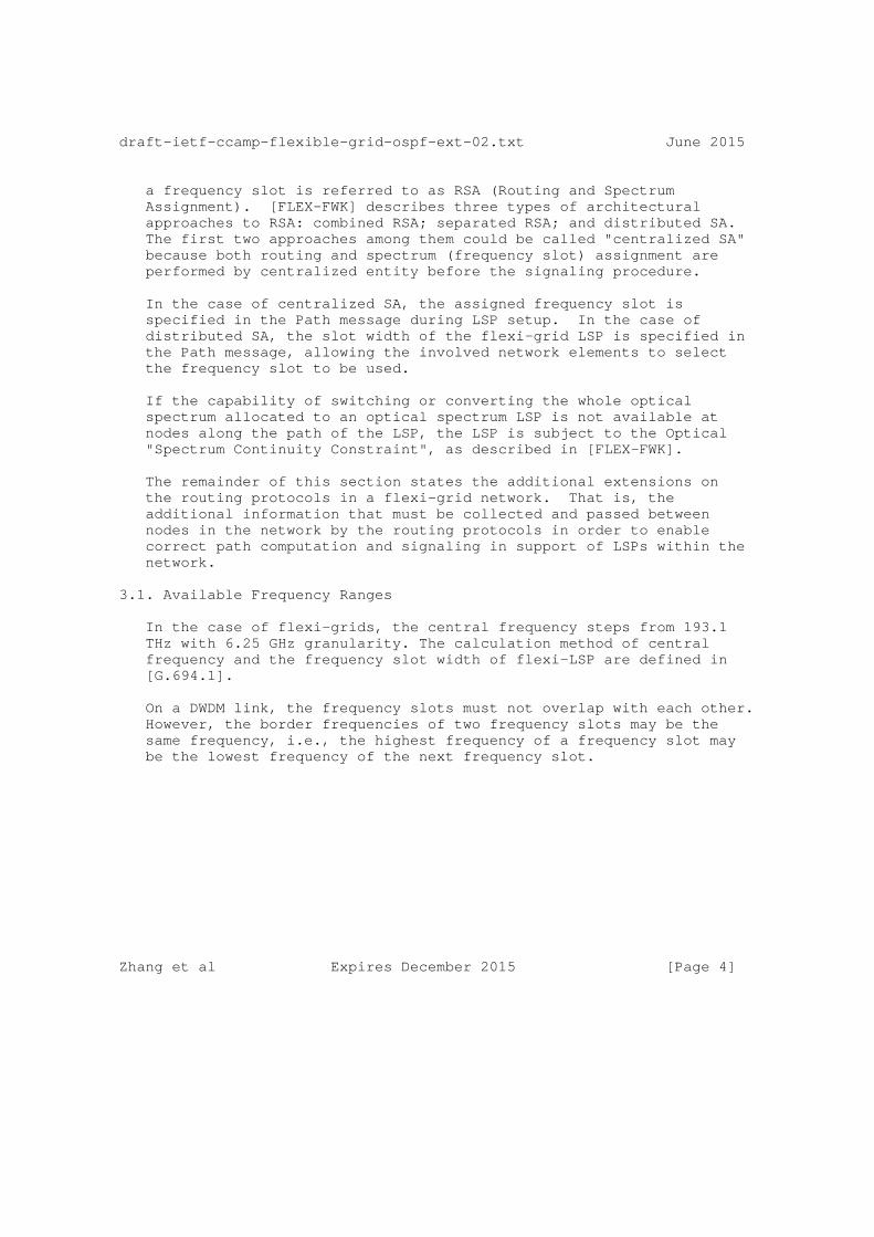
draft-ietf-ccamp-flexible-grid-ospf-ext-02.txt June 2015
a frequency slot is referred to as RSA (Routing and Spectrum Assignment). [FLEX-FWK] describes three types of architectural approaches to RSA: combined RSA; separated RSA; and distributed SA. The first two approaches among them could be called "centralized SA" because both routing and spectrum (frequency slot) assignment are performed by centralized entity before the signaling procedure.
In the case of centralized SA, the assigned frequency slot is specified in the Path message during LSP setup. In the case of distributed SA, the slot width of the flexi-grid LSP is specified in the Path message, allowing the involved network elements to select the frequency slot to be used.
If the capability of switching or converting the whole optical spectrum allocated to an optical spectrum LSP is not available at nodes along the path of the LSP, the LSP is subject to the Optical "Spectrum Continuity Constraint", as described in [FLEX-FWK].
The remainder of this section states the additional extensions on the routing protocols in a flexi-grid network. That is, the additional information that must be collected and passed between nodes in the network by the routing protocols in order to enable correct path computation and signaling in support of LSPs within the network.
3.1. Available Frequency Ranges
In the case of flexi-grids, the central frequency steps from 193.1 THz with 6.25 GHz granularity. The calculation method of central frequency and the frequency slot width of flexi-LSP are defined in [G.694.1].
On a DWDM link, the frequency slots must not overlap with each other. However, the border frequencies of two frequency slots may be the same frequency, i.e., the highest frequency of a frequency slot may be the lowest frequency of the next frequency slot.
Zhang et al Expires December 2015 [Page 4]

draft-ietf-ccamp-flexible-grid-ospf-ext-02.txt June 2015
Frequency Slot 1 Frequency Slot 2 +-----------+-----------------------+ | | | -9 -8 -7 -6 -5 -4 -3 -2 -1 0 1 2 3 4 5 6 7 8 9 10 11 ...+--+--+--+--+--+--+--+--+--+--+--+--+--+--+--+--+--+--+--+--+--... ------------ ------------------------ ^ ^ Central F = 193.1THz Central F = 193.1375 THz Slot width = 25 GHz Slot width = 50 GHz
Figure 1 - Two Frequency Slots on a Link
Figure 1 shows two adjacent frequency slots on a link. The highest frequency of frequency slot 1 denoted by n=2 is the lowest frequency of slot 2. In this example, it means that the frequency range from n=-2 to n=10 is occupied and is unavailable to other flexi-LSPs.
Hence, in order to clearly show which LSPs can be supported and what frequency slots are unavailable, the available frequency ranges should be advertised by the routing protocol for the flexi-grid DWDM links. A set of non-overlapping available frequency ranges should be disseminated in order to allow efficient resource management of flexi-grid DWDM links and RSA procedures which are described in section 5.8 of [FLEX-FWK].
3.2. Application Compliance Considerations
As described in [G.694.1], devices or applications that make use of the flexi-grid may not be capable of supporting every possible slot width or position (i.e., central frequency). In other words, applications or implementations may be defined where only a subset of the possible slot widths and positions are required to be supported.
For example, an application could be defined where the nominal central frequency granularity is 12.5 GHz (by only requiring values of n that are even) and that only requires slot widths as a multiple of 25 GHz (by only requiring values of m that are even).
Hence, in order to support all possible applications and implementations the following information should be advertised for a flexi-grid DWDM link:
o Central frequency granularity: a multiplier of 6.25 GHz.
o Slot width granularity: a multiplier of 12.5 GHz.
Zhang et al Expires December 2015 [Page 5]
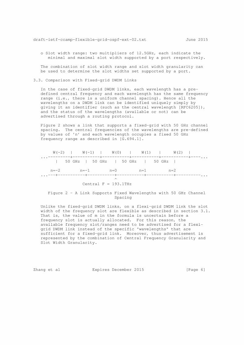
draft-ietf-ccamp-flexible-grid-ospf-ext-02.txt June 2015
o Slot width range: two multipliers of 12.5GHz, each indicate the minimal and maximal slot width supported by a port respectively.
The combination of slot width range and slot width granularity can be used to determine the slot widths set supported by a port.
3.3. Comparison with Fixed-grid DWDM Links
In the case of fixed-grid DWDM links, each wavelength has a pre- defined central frequency and each wavelength has the same frequency range (i.e., there is a uniform channel spacing). Hence all the wavelengths on a DWDM link can be identified uniquely simply by giving it an identifier (such as the central wavelength [RFC6205]), and the status of the wavelengths (available or not) can be advertised through a routing protocol.
Figure 2 shows a link that supports a fixed-grid with 50 GHz channel spacing. The central frequencies of the wavelengths are pre-defined by values of ’n’ and each wavelength occupies a fixed 50 GHz frequency range as described in [G.694.1].
W(-2) | W(-1) | W(0) | W(1) | W(2) | ...---------+-----------+-----------+-----------+-----------+----... | 50 GHz | 50 GHz | 50 GHz | 50 GHz |
n=-2 n=-1 n=0 n=1 n=2 ...---+-----------+-----------+-----------+-----------+----------... ^ Central F = 193.1THz
Figure 2 - A Link Supports Fixed Wavelengths with 50 GHz Channel Spacing
Unlike the fixed-grid DWDM links, on a flexi-grid DWDM link the slot width of the frequency slot are flexible as described in section 3.1. That is, the value of m in the formula is uncertain before a frequency slot is actually allocated. For this reason, the available frequency slot/ranges need to be advertised for a flexi- grid DWDM link instead of the specific "wavelengths" that are sufficient for a fixed-grid link. Moreover, thus advertisement is represented by the combination of Central Frequency Granularity and Slot Width Granularity.
Zhang et al Expires December 2015 [Page 6]
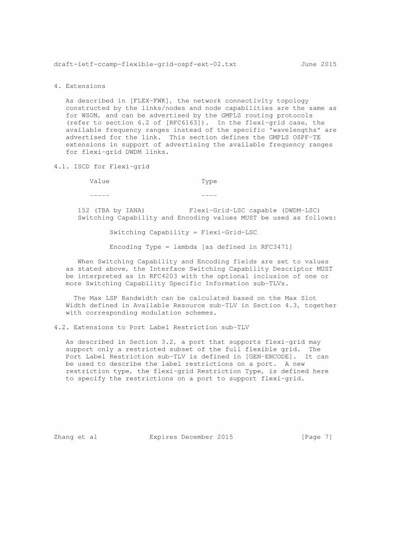
draft-ietf-ccamp-flexible-grid-ospf-ext-02.txt June 2015
4. Extensions
As described in [FLEX-FWK], the network connectivity topology constructed by the links/nodes and node capabilities are the same as for WSON, and can be advertised by the GMPLS routing protocols (refer to section 6.2 of [RFC6163]). In the flexi-grid case, the available frequency ranges instead of the specific "wavelengths" are advertised for the link. This section defines the GMPLS OSPF-TE extensions in support of advertising the available frequency ranges for flexi-grid DWDM links.
4.1. ISCD for Flexi-grid
Value Type
----- ----
152 (TBA by IANA) Flexi-Grid-LSC capable (DWDM-LSC) Switching Capability and Encoding values MUST be used as follows:
Switching Capability = Flexi-Grid-LSC
Encoding Type = lambda [as defined in RFC3471]
When Switching Capability and Encoding fields are set to values as stated above, the Interface Switching Capability Descriptor MUST be interpreted as in RFC4203 with the optional inclusion of one or more Switching Capability Specific Information sub-TLVs.
The Max LSP Bandwidth can be calculated based on the Max Slot Width defined in Available Resource sub-TLV in Section 4.3, together with corresponding modulation schemes.
4.2. Extensions to Port Label Restriction sub-TLV
As described in Section 3.2, a port that supports flexi-grid may support only a restricted subset of the full flexible grid. The Port Label Restriction sub-TLV is defined in [GEN-ENCODE]. It can be used to describe the label restrictions on a port. A new restriction type, the flexi-grid Restriction Type, is defined here to specify the restrictions on a port to support flexi-grid.
Zhang et al Expires December 2015 [Page 7]

draft-ietf-ccamp-flexible-grid-ospf-ext-02.txt June 2015
0 1 2 3 0 1 2 3 4 5 6 7 8 9 0 1 2 3 4 5 6 7 8 9 0 1 2 3 4 5 6 7 8 9 0 1 +-+-+-+-+-+-+-+-+-+-+-+-+-+-+-+-+-+-+-+-+-+-+-+-+-+-+-+-+-+-+-+-+ | MatrixID | RstType = TBA | Switching Cap | Encoding | +-+-+-+-+-+-+-+-+-+-+-+-+-+-+-+-+-+-+-+-+-+-+-+-+-+-+-+-+-+-+-+-+ | C.F.G | S.W.G | Min Slot Width | +-+-+-+-+-+-+-+-+-+-+-+-+-+-+-+-+-+-+-+-+-+-+-+-+-+-+-+-+-+-+-+-+
MatrixID (8 bits): As defined in [GEN-ENCODE].
RstType (Restriction Type, 8 bits): Takes the value (TBA) to indicate the restrictions on a port to support flexi-grid.
Switching Cap (Switching Capability, 8 bits): As defined in [GEN- ENCODE], must be consistent with the one specified in ISCD as described in Section 4.1.
Encoding (8 bits): As defined in [GEN-ENCODE], must be consistent with the one specified in ISCD as described in Section 4.1.
C.F.G (Central Frequency Granularity, 8 bits): A positive integer. Its value indicates the multiple of 6.25 GHz in terms of central frequency granularity.
S.W.G (Slot Width Granularity, 8 bits): A positive integer. Its value indicates the multiple of 12.5 GHz in terms of slot width granularity.
Min Slot Width (16 bits): A positive integer. Its value indicates the multiple of 12.5 GHz in terms of the supported minimal slot width.
4.3. Available Resource sub-TLV
The Available Resource sub-TLV is defined to support indicating the flexi-grid label availability as follow:
Zhang et al Expires December 2015 [Page 8]
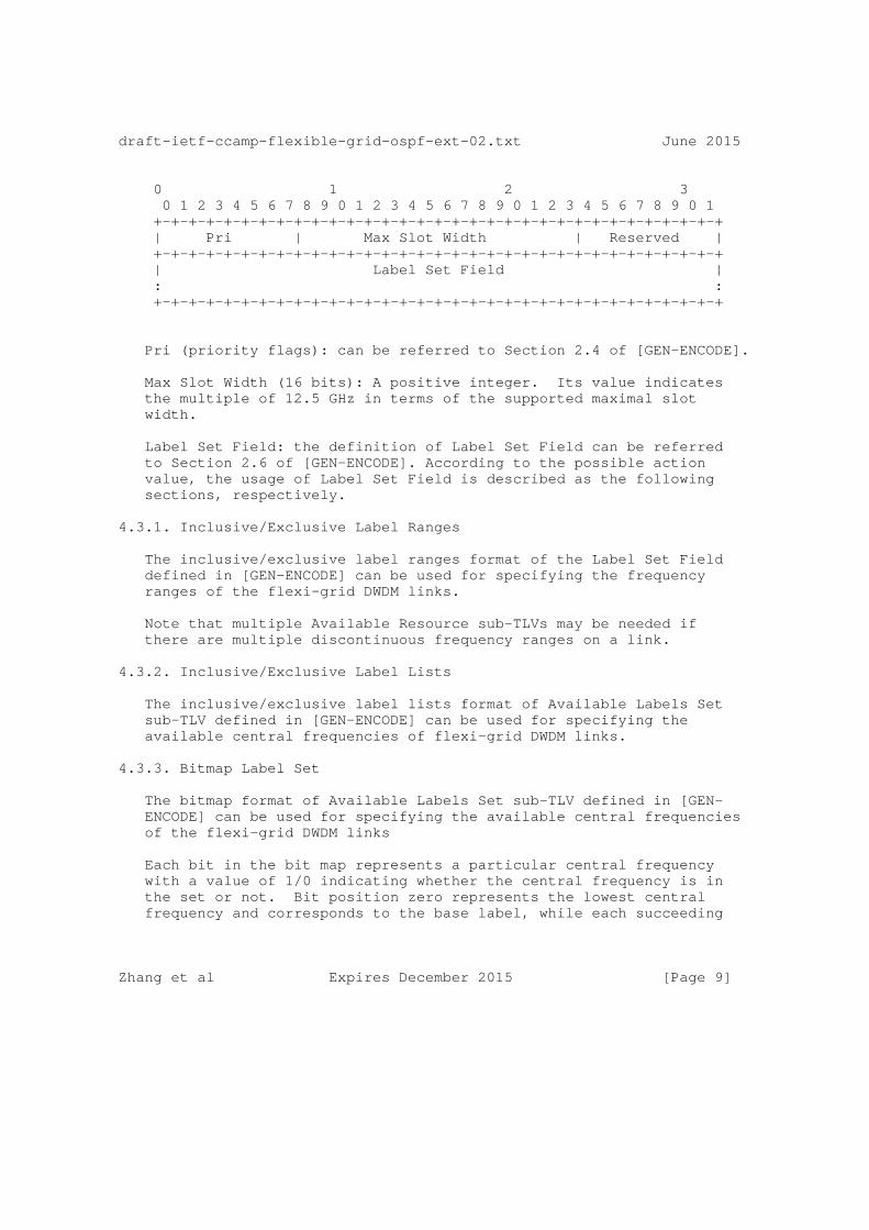
draft-ietf-ccamp-flexible-grid-ospf-ext-02.txt June 2015
0 1 2 3 0 1 2 3 4 5 6 7 8 9 0 1 2 3 4 5 6 7 8 9 0 1 2 3 4 5 6 7 8 9 0 1 +-+-+-+-+-+-+-+-+-+-+-+-+-+-+-+-+-+-+-+-+-+-+-+-+-+-+-+-+-+-+-+-+ | Pri | Max Slot Width | Reserved | +-+-+-+-+-+-+-+-+-+-+-+-+-+-+-+-+-+-+-+-+-+-+-+-+-+-+-+-+-+-+-+-+ | Label Set Field | : : +-+-+-+-+-+-+-+-+-+-+-+-+-+-+-+-+-+-+-+-+-+-+-+-+-+-+-+-+-+-+-+-+
Pri (priority flags): can be referred to Section 2.4 of [GEN-ENCODE].
Max Slot Width (16 bits): A positive integer. Its value indicates the multiple of 12.5 GHz in terms of the supported maximal slot width.
Label Set Field: the definition of Label Set Field can be referred to Section 2.6 of [GEN-ENCODE]. According to the possible action value, the usage of Label Set Field is described as the following sections, respectively.
4.3.1. Inclusive/Exclusive Label Ranges
The inclusive/exclusive label ranges format of the Label Set Field defined in [GEN-ENCODE] can be used for specifying the frequency ranges of the flexi-grid DWDM links.
Note that multiple Available Resource sub-TLVs may be needed if there are multiple discontinuous frequency ranges on a link.
4.3.2. Inclusive/Exclusive Label Lists
The inclusive/exclusive label lists format of Available Labels Set sub-TLV defined in [GEN-ENCODE] can be used for specifying the available central frequencies of flexi-grid DWDM links.
4.3.3. Bitmap Label Set
The bitmap format of Available Labels Set sub-TLV defined in [GEN- ENCODE] can be used for specifying the available central frequencies of the flexi-grid DWDM links
Each bit in the bit map represents a particular central frequency with a value of 1/0 indicating whether the central frequency is in the set or not. Bit position zero represents the lowest central frequency and corresponds to the base label, while each succeeding
Zhang et al Expires December 2015 [Page 9]

draft-ietf-ccamp-flexible-grid-ospf-ext-02.txt June 2015
bit position represents the next central frequency logically above the previous.
Examples of the Available Resource sub-TLV can be found in Section 4.4.
4.4. Examples for Available Resource Sub-TLV
Figure 3 shows an example of available frequency range of a flexi- grid DWDM link.
-9 -8 -7 -6 -5 -4 -3 -2 -1 0 1 2 3 4 5 6 7 8 9 10 11 ...+--+--+--+--+--+--+--+--+--+--+--+--+--+--+--+--+--+--+--+--+--... |--Available Frequency Range--|
Figure 3 - Flexi-grid DWDM Link
The symbol ’+’ represents the allowed nominal central frequency. The symbol "--" represents a 6.25 GHz frequency unit. The number on the top of the line represents the ’n’ in the frequency calculation formula (193.1 + n * 0.00625). The nominal central frequency is 193.1 THz when n equals zero.
The usage of Action, Number of Labels and Length session of the Label set field can be referred to Section 2.6 in [GEN-ENCODE].
Assume that the central frequency granularity is 6.25GHz, the label set can be encoded as follows:
Inclusive Label Range:
o Start Slot = -2; o End Slot = 8.
The available central frequencies (-1, 0, 1, 2, 3, 4, 5, 6, 7) can be deduced by the Inclusive Label Range, because the Central Frequency Granularity is 6.25 GHz.
Inclusive Label Lists:
Zhang et al Expires December 2015 [Page 10]

draft-ietf-ccamp-flexible-grid-ospf-ext-02.txt June 2015
o List Entry 1 = slot -1; o List Entry 2 = slot 0; o List Entry 3 = slot 1; o List Entry 4 = slot 2; o List Entry 5 = slot 3; o List Entry 6 = slot 4; o List Entry 7 = slot 5; o List Entry 8 = slot 6; o List Entry 9 = slot 7.
Bitmap:
o Base Slot = -1; o Bitmap = 111111111(padded out to a full multiple of 32 bits)
5. IANA Considerations
[GEN-OSPF] defines the Port label Restriction sub-TLV of OSPF TE Link TLV. It also creates a registry of values of the Restriction Type field of that sub-TLV
IANA is requested to assign a new value from that registry as follows:
Value Meaning Reference
TBD Flexi-grid restriction [This.I-D]
6. Implementation Status
[RFC Editor Note: Please remove this entire seciton prior to publication as an RFC.]
This section records the status of known implementations of the protocol defined by this specification at the time of posting of this Internet-Draft, and is based on a proposal described in RFC 6982[RFC6982]. The description of implementations in this section is intended to assist the IETF in its decision processes in progressing drafts to RFCs. Please note that the listing of any individual implementation here does not imply endorsement by the IETF. Furthermore, no effort has been spent to verify the information presented here that was supplied by IETF contributors. This is not intended as, and must not be construed to be, a catalog of available implementations or their features. Readers are advised to note that other implementations may exist.
Zhang et al Expires December 2015 [Page 11]

draft-ietf-ccamp-flexible-grid-ospf-ext-02.txt June 2015
According to RFC 6982, "this will allow reviewers and working groups to assign due consideration to documents that have the benefit of running code, which may serve as evidence of valuable experimentation and feedback that have made the implemented protocols more mature. It is up to the individual working groups to use this information as they see fit.
6.1. Centre Tecnologic de Telecomunicacions de Catalunya (CTTC)
Organization Responsible for the Implementation: CTTC - Centre Tecnologic de Telecomunicacions de Catalunya (CTTC), Optical Networks and Systems Department, http://wikiona.cttc.es.
Implementation Name and Details: ADRENALINE testbed, http://networks.cttc.es/experimental-testbeds/
Brief Description: Experimental testbed implementation of GMPLS/PCE control plane.
Level of Maturity: Implemented as extensions to a mature GMLPS/PCE control plane. It is limited to research / prototyping stages but it has been used successfully for more than the last five years.
Coverage: Support for the 64 bit label [FLEC-LBL] for flexi-grid as described in this document, with available label set encoded as bitmap.
It is expected that this implementation will evolve to follow the evolution of this document.
Licensing: Proprietary
Implementation Experience: Implementation of this document reports no issues. General implementation experience has been reported in a number of journal papers. Contact Ramon Casellas for more information or see http://networks.cttc.es/publications/? search=GMPLS&research_area=optical-networks-systems
Contact Information: Ramon Casellas: [email protected]
Interoperability: No report.
Zhang et al Expires December 2015 [Page 12]
draft-ietf-ccamp-flexible-grid-ospf-ext-02.txt June 2015
7. Acknowledgments
This work was supported in part by the FP-7 IDEALIST project under grant agreement number 317999.
8. Security Considerations
This document does not introduce any further security issues other than those discussed in [RFC3630], [RFC4203].
9. References
9.1. Normative References
[RFC2119] S. Bradner, "Key words for use in RFCs to indicate requirements levels", RFC 2119, March 1997.
[G.694.1] ITU-T Recommendation G.694.1 (revision 2), "Spectral grids for WDM applications: DWDM frequency grid", February 2012.
[GEN-ENCODE] Bernstein, G., Lee, Y., Li, D., and W. Imajuku, "General Network Element Constraint Encoding for GMPLS Controlled Networks", draft-ietf-ccamp-general-constraint- encode, work in progress.
[GEN-OSPF] Fatai Zhang, Y. Lee, Jianrui Han, G. Bernstein and Yunbin Xu, " OSPF-TE Extensions for General Network Element Constraints ", draft-ietf-ccamp-gmpls-general-constraints- ospf-te, work in progress.
[RFC6205] T. Otani and D. Li, "Generalized Labels for Lambda-Switch- Capable (LSC) Label Switching Routers", RFC 6205, March 2011.
[FLEX-LBL] King, D., Farrel, A. and Y. Li, "Generalized Labels for the Flexi-Grid in Lambda Switch Capable (LSC) Label Switching Routers", draft-farrkingel-ccamp-flexigrid- lambda-label, work in progress.
9.2. Informative References
[RFC6163] Y. Lee, G. Bernstein and W. Imajuku, "Framework for GMPLS and Path Computation Element (PCE) Control of Wavelength Switched Optical Networks (WSONs)", RFC 6163, April 2011.
Zhang et al Expires December 2015 [Page 13]

draft-ietf-ccamp-flexible-grid-ospf-ext-02.txt June 2015
[FLEX-SIG] F.Zhang et al, "RSVP-TE Signaling Extensions in support of Flexible-grid", draft-ietf-ccamp-flexible-grid-rsvp- te-ext, work in progress.
[FLEX-FWK] Gonzalez de Dios, O,, Casellas R., Zhang, F., Fu, X., Ceccarelli, D., and I. Hussain, "Framework and Requirements for GMPLS based control of Flexi-grid DWDM networks’, draft-ietf-ccamp-flexi-grid-fwk, work in progress.
[WSON-OSPF] Y. Lee and G. Bernstein, "GMPLS OSPF Enhancement for Signal and Network Element Compatibility for Wavelength Switched Optical Networks ", draft-ietf-ccamp-wson-signal- compatibility-ospf, work in progress.
Zhang et al Expires December 2015 [Page 14]
draft-ietf-ccamp-flexible-grid-ospf-ext-02.txt June 2015
10. Authors’ Addresses
Xian Zhang Huawei Technologies Email: [email protected]
Haomian Zheng Huawei Technologies Email: [email protected]
Ramon Casellas, Ph.D. CTTC Spain Phone: +34 936452916 Email: [email protected]
Oscar Gonzalez de Dios Telefonica Investigacion y Desarrollo Emilio Vargas 6 Madrid, 28045 Spain Phone: +34 913374013 Email: [email protected]
Daniele Ceccarelli Ericsson Via A. Negrone 1/A Genova - Sestri Ponente Italy Email: [email protected]
11. Contributors’ Addresses
Adrian Farrel Old Dog Consulting Email: [email protected]
Fatai Zhang Huawei Technologies Email: [email protected]
Lei Wang, ZTE Email: [email protected]
Zhang et al Expires December 2015 [Page 15]

Network Working Group H. Long, M.YeInternet Draft Huawei Technologies Co., LtdIntended status: Standards Track G. Mirsky Ericsson A.D’Alessandro Telecom Italia S.p.A H. Shah CienaExpires: January 2016 July 6, 2015
OSPF Routing Extension for Links with Variable Discrete Bandwidth draft-ietf-ccamp-ospf-availability-extension-02.txt
Abstract
A packet switching network MAY contain links with variable discrete bandwidth, e.g., copper, radio, etc. The bandwidth of such links MAY change discretely in reaction to changing external environment. Availability is typically used for describing such links during network planning. This document introduces an OPTIONAL ISCD Availability sub-TLV in OSPF routing protocol. This extension can be used for route computation in a Packet Switched Network (PSN) that contains links with discretely variable bandwidth.
Status of this Memo
This Internet-Draft is submitted in full conformance with the provisions of BCP 78 and BCP 79.
Internet-Drafts are working documents of the Internet Engineering Task Force (IETF), its areas, and its working groups. Note that other groups may also distribute working documents as Internet- Drafts.
Internet-Drafts are draft documents valid for a maximum of six months and may be updated, replaced, or obsoleted by other documents at any time. It is inappropriate to use Internet-Drafts as reference material or to cite them other than as "work in progress."
The list of current Internet-Drafts can be accessed at http://www.ietf.org/ietf/1id-abstracts.txt
Long, et al. Expires January 6, 2016 [Page 1]

Internet-Draft OSPF - Availability extension July 2015
The list of Internet-Draft Shadow Directories can be accessed at http://www.ietf.org/shadow.html
This Internet-Draft will expire on January 6, 2016.
Copyright Notice
Copyright (c) 2015 IETF Trust and the persons identified as the document authors. All rights reserved.
This document is subject to BCP 78 and the IETF Trust’s Legal Provisions Relating to IETF Documents (http://trustee.ietf.org/license-info) in effect on the date of publication of this document. Please review these documents carefully, as they describe your rights and restrictions with respect to this document. Code Components extracted from this document must include Simplified BSD License text as described in Section 4.e of the Trust Legal Provisions and are provided without warranty as described in the Simplified BSD License.
Table of Contents
1. Introduction ................................................ 3 2. Overview .................................................... 4 3. Extension to OSPF Routing Protocol........................... 4 3.1. Interface Switching Capacity Descriptor................. 4 3.2. ISCD Availability sub-TLV............................... 5 3.3. Signaling Process....................................... 6 4. Security Considerations...................................... 7 5. IANA Considerations ......................................... 7 6. References .................................................. 7 6.1. Normative References.................................... 7 6.2. Informative References.................................. 8 7. Acknowledgments ............................................. 8
Conventions used in this document
The key words "MUST", "MUST NOT", "REQUIRED", "SHALL", "SHALL NOT", "SHOULD", "SHOULD NOT", "RECOMMENDED", "MAY", and "OPTIONAL" in this document are to be interpreted as described in RFC-2119 [RFC2119].
The following acronyms are used in this draft:
OSPF Open Shortest Path First
PSN Packet Switched Network
Long, et al. Expires January 6, 2016 [Page 2]
Internet-Draft OSPF - Availability extension July 2015
SNR Signal-to-noise Ratio
LSP Label Switched Path
ISCD Interface Switching Capacity Descriptor
PE Provider Edge
LSA Link State Advertisement
1. Introduction
Some data communication technologies allow seamless change of maximum physical bandwidth through a set of known discrete values. For example, in mobile backhaul network, microwave links are very popular for providing connection of last hops. In case of heavy rain, to maintain the link connectivity, the microwave link MAY lower the modulation level since demodulating the lower modulation level needs lower signal-to-noise ratio (SNR). This is called adaptive modulation technology [EN 302 217]. However, a lower modulation level also means lower link bandwidth. When link bandwidth is reduced because of modulation down-shifting, high-priority traffic can be maintained, while lower-priority traffic is dropped. Similarly, the copper links MAY change their effective link bandwidth due to external interference.
The parameter availability [G.827, F.1703, P.530] is often used to describe the link capacity during network planning. Assigning different availability classes to different types of service over such kind of links provides more efficient planning of link capacity. To set up an LSP across these links, availability information is required for the nodes to verify bandwidth satisfaction and make bandwidth reservation. The availability information SHOULD be inherited from the availability requirements of the services expected to be carried on the LSP. For example, voice service usually needs "five nines" availability, while non-real time services MAY adequately perform at four or three nines availability.
For the route computation, the availability information SHOULD be provided along with bandwidth resource information. In this document, an extension on Interface Switching Capacity Descriptor (ISCD) [RFC4202] for availability information is defined to support in routing signaling. The extension reuses the reserved field in the ISCD and also introduces an OPTIONAL Availability sub-TLV.
If there is a hop that cannot support the Availability sub-TLV, the Availability sub-TLV SHOULD be ignored.
Long, et al. Expires January 6, 2016 [Page 3]

Internet-Draft OSPF - Availability extension July 2015
2. Overview
A node which has link(s) with variable bandwidth attached SHOULD contain a <bandwidth, availability> information list in its OSPF TE LSA messages. The list provides the information that how much bandwidth a link can support for a specified availability. This information is used for path calculation by the PE node(s).
To setup an label switching path (LSP), a PE node MAY collect link information which is spread in OSPF TE LSA messages by network nodes to get know about the network topology, calculate out an LSP route based on the network topology and send the calculated LSP route to signaling to initiate a PATH/RESV message for setting up the LSP.
Availability information is required to carry in the signaling message to better utilize the link bandwidth. The signaling extension for availability can be found in [ASTE].
3. Extension to OSPF Routing Protocol
3.1. Interface Switching Capacity Descriptor
The Interface Switching Capacity Descriptor (ISCD) sub-TLV [RFC 4203] has the following format:
Long, et al. Expires January 6, 2016 [Page 4]
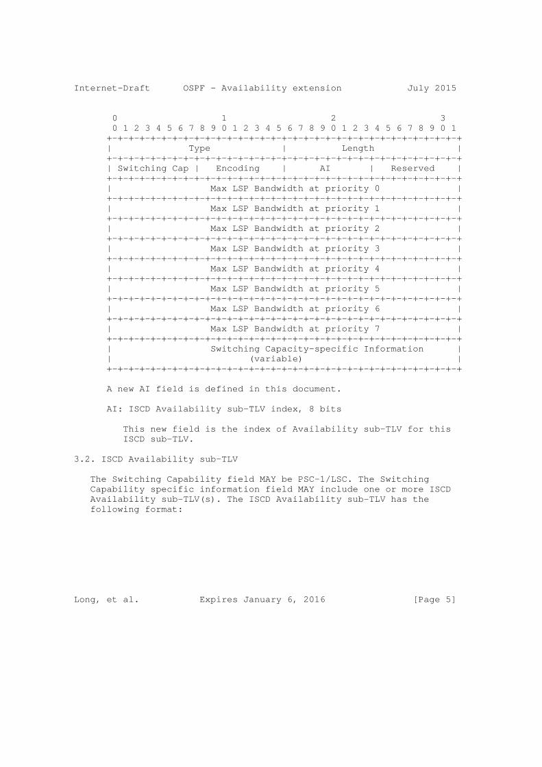
Internet-Draft OSPF - Availability extension July 2015
0 1 2 3 0 1 2 3 4 5 6 7 8 9 0 1 2 3 4 5 6 7 8 9 0 1 2 3 4 5 6 7 8 9 0 1 +-+-+-+-+-+-+-+-+-+-+-+-+-+-+-+-+-+-+-+-+-+-+-+-+-+-+-+-+-+-+-+-+ | Type | Length | +-+-+-+-+-+-+-+-+-+-+-+-+-+-+-+-+-+-+-+-+-+-+-+-+-+-+-+-+-+-+-+-+ | Switching Cap | Encoding | AI | Reserved | +-+-+-+-+-+-+-+-+-+-+-+-+-+-+-+-+-+-+-+-+-+-+-+-+-+-+-+-+-+-+-+-+ | Max LSP Bandwidth at priority 0 | +-+-+-+-+-+-+-+-+-+-+-+-+-+-+-+-+-+-+-+-+-+-+-+-+-+-+-+-+-+-+-+-+ | Max LSP Bandwidth at priority 1 | +-+-+-+-+-+-+-+-+-+-+-+-+-+-+-+-+-+-+-+-+-+-+-+-+-+-+-+-+-+-+-+-+ | Max LSP Bandwidth at priority 2 | +-+-+-+-+-+-+-+-+-+-+-+-+-+-+-+-+-+-+-+-+-+-+-+-+-+-+-+-+-+-+-+-+ | Max LSP Bandwidth at priority 3 | +-+-+-+-+-+-+-+-+-+-+-+-+-+-+-+-+-+-+-+-+-+-+-+-+-+-+-+-+-+-+-+-+ | Max LSP Bandwidth at priority 4 | +-+-+-+-+-+-+-+-+-+-+-+-+-+-+-+-+-+-+-+-+-+-+-+-+-+-+-+-+-+-+-+-+ | Max LSP Bandwidth at priority 5 | +-+-+-+-+-+-+-+-+-+-+-+-+-+-+-+-+-+-+-+-+-+-+-+-+-+-+-+-+-+-+-+-+ | Max LSP Bandwidth at priority 6 | +-+-+-+-+-+-+-+-+-+-+-+-+-+-+-+-+-+-+-+-+-+-+-+-+-+-+-+-+-+-+-+-+ | Max LSP Bandwidth at priority 7 | +-+-+-+-+-+-+-+-+-+-+-+-+-+-+-+-+-+-+-+-+-+-+-+-+-+-+-+-+-+-+-+-+ | Switching Capacity-specific Information | | (variable) | +-+-+-+-+-+-+-+-+-+-+-+-+-+-+-+-+-+-+-+-+-+-+-+-+-+-+-+-+-+-+-+-+
A new AI field is defined in this document.
AI: ISCD Availability sub-TLV index, 8 bits
This new field is the index of Availability sub-TLV for this ISCD sub-TLV.
3.2. ISCD Availability sub-TLV
The Switching Capability field MAY be PSC-1/LSC. The Switching Capability specific information field MAY include one or more ISCD Availability sub-TLV(s). The ISCD Availability sub-TLV has the following format:
Long, et al. Expires January 6, 2016 [Page 5]
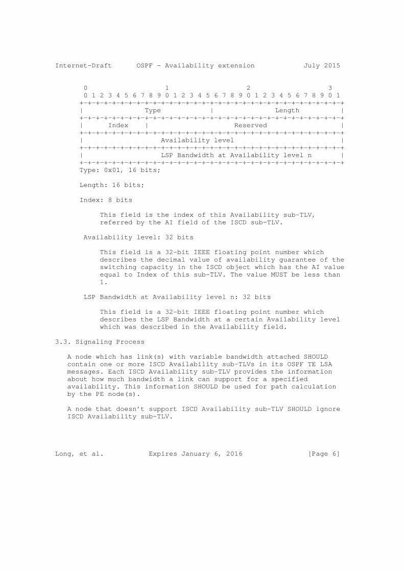
Internet-Draft OSPF - Availability extension July 2015
0 1 2 3 0 1 2 3 4 5 6 7 8 9 0 1 2 3 4 5 6 7 8 9 0 1 2 3 4 5 6 7 8 9 0 1 +-+-+-+-+-+-+-+-+-+-+-+-+-+-+-+-+-+-+-+-+-+-+-+-+-+-+-+-+-+-+-+-+ | Type | Length | +-+-+-+-+-+-+-+-+-+-+-+-+-+-+-+-+-+-+-+-+-+-+-+-+-+-+-+-+-+-+-+-+ | Index | Reserved | +-+-+-+-+-+-+-+-+-+-+-+-+-+-+-+-+-+-+-+-+-+-+-+-+-+-+-+-+-+-+-+-+ | Availability level | +-+-+-+-+-+-+-+-+-+-+-+-+-+-+-+-+-+-+-+-+-+-+-+-+-+-+-+-+-+-+-+-+ | LSP Bandwidth at Availability level n | +-+-+-+-+-+-+-+-+-+-+-+-+-+-+-+-+-+-+-+-+-+-+-+-+-+-+-+-+-+-+-+-+ Type: 0x01, 16 bits;
Length: 16 bits;
Index: 8 bits
This field is the index of this Availability sub-TLV, referred by the AI field of the ISCD sub-TLV.
Availability level: 32 bits
This field is a 32-bit IEEE floating point number which describes the decimal value of availability guarantee of the switching capacity in the ISCD object which has the AI value equal to Index of this sub-TLV. The value MUST be less than 1.
LSP Bandwidth at Availability level n: 32 bits
This field is a 32-bit IEEE floating point number which describes the LSP Bandwidth at a certain Availability level which was described in the Availability field.
3.3. Signaling Process
A node which has link(s) with variable bandwidth attached SHOULD contain one or more ISCD Availability sub-TLVs in its OSPF TE LSA messages. Each ISCD Availability sub-TLV provides the information about how much bandwidth a link can support for a specified availability. This information SHOULD be used for path calculation by the PE node(s).
A node that doesn’t support ISCD Availability sub-TLV SHOULD ignore ISCD Availability sub-TLV.
Long, et al. Expires January 6, 2016 [Page 6]
Internet-Draft OSPF - Availability extension July 2015
4. Security Considerations
This document does not introduce new security considerations to the existing OSPF protocol.
5. IANA Considerations
This document introduces an Availability sub-TLV of the ISCD sub-TLV of the TE Link TLV in the TE Opaque LSA for OSPF v2. This document proposes a suggested value for the Availability sub-TLV; it is recommended that the suggested value be granted by IANA. Initial values are as follows:
Type Length Format Description
--- ---- ------------------ -----------
0 - Reserved Reserved value
0x01 8 see Section 3.2 Availability
6. References
6.1. Normative References
[RFC2210] Wroclawski, J., "The Use of RSVP with IETF Integrated Services", RFC 2210, September 1997.
[RFC3209] Awduche, D., Berger, L., Gan, D., Li, T., Srinivasan, V.,and G. Swallow, "RSVP-TE: Extensions to RSVP for LSP Tunnels", RFC 3209, December 2001.
[RFC3473] Berger, L., "Generalized Multi-Protocol Label Switching (GMPLS) Signaling Resource ReserVation Protocol-Traffic Engineering (RSVP-TE) Extensions", RFC 3473, January 2003.
[RFC4202] Kompella, K. and Rekhter, Y. (Editors), "Routing Extensions in Support of Generalized Multi-Protocol Label Switching (GMPLS)", RFC 4202, October 2005.
[RFC4203] Kompella, K., Ed., and Y. Rekhter, Ed., "OSPF Extensions in Support of Generalized Multi-Protocol Label Switching (GMPLS)", RFC 4203, October 2005.
[G.827] ITU-T Recommendation, "Availability performance parameters and objectives for end-to-end international constant bit- rate digital paths", September, 2003.
Long, et al. Expires January 6, 2016 [Page 7]
Internet-Draft OSPF - Availability extension July 2015
[F.1703] ITU-R Recommendation, "Availability objectives for real digital fixed wireless links used in 27 500 km hypothetical reference paths and connections", January, 2005.
[P.530] ITU-R Recommendation," Propagation data and prediction methods required for the design of terrestrial line-of- sight systems", February, 2012
[EN 302 217] ETSI standard, "Fixed Radio Systems; Characteristics and requirements for point-to-point equipment and antennas", April, 2009
[ASTE] H., Long, M., Ye, Mirsky, G., Alessandro, A., Shah, H., "RSVP-TE Signaling Extension for Links with Variable Discrete Bandwidth", Work in Progress, February, 2014
6.2. Informative References
[MCOS] Minei, I., Gan, D., Kompella, K., and X. Li, "Extensions for Differentiated Services-aware Traffic Engineered LSPs", Work in Progress, June 2006.
7. Acknowledgments
Authors’ Addresses
Long, et al. Expires January 6, 2016 [Page 8]
Internet-Draft OSPF - Availability extension July 2015
Hao Long Huawei Technologies Co., Ltd. No.1899, Xiyuan Avenue, Hi-tech Western District Chengdu 611731, P.R.China
Phone: +86-18615778750 Email: [email protected]
Min Ye Huawei Technologies Co., Ltd. No.1899, Xiyuan Avenue, Hi-tech Western District Chengdu 611731, P.R.China
Email: [email protected]
Greg Mirsky Ericsson
Email: [email protected]
Alessandro D’Alessandro Telecom Italia S.p.A
Email: [email protected]
Himanshu Shah Ciena Corp. 3939 North First Street San Jose, CA 95134 US
Email: [email protected]
Long, et al. Expires January 6, 2016 [Page 9]

Network Working Group H. Long, M. YeInternet Draft Huawei Technologies Co., LtdIntended status: Standards Track G. Mirsky Ericsson A.D’Alessandro Telecom Italia S.p.A H. Shah CienaExpires: January 2016 July 2, 2015
RSVP-TE Signaling Extension for Links with Variable Discrete Bandwidth draft-ietf-ccamp-rsvp-te-bandwidth-availability-02.txt
Abstract
A Packet switching network MAY contain links with variable bandwidth, e.g., copper, radio, etc. The bandwidth of such links is sensitive to external environment. Availability is typically used for describing the link during network planning. This document introduces an Extended Ethernet Bandwidth Profile TLV and an OPTIONAL Availability sub-TLV in RSVP-TE signaling. This extension can be used to set up a label switching path (LSP) in a Packet Switched Network (PSN) that contains links with discretely variable bandwidth.
Status of this Memo
This Internet-Draft is submitted in full conformance with the provisions of BCP 78 and BCP 79.
Internet-Drafts are working documents of the Internet Engineering Task Force (IETF), its areas, and its working groups. Note that other groups may also distribute working documents as Internet- Drafts.
Internet-Drafts are draft documents valid for a maximum of six months and may be updated, replaced, or obsoleted by other documents at any time. It is inappropriate to use Internet-Drafts as reference material or to cite them other than as "work in progress."
The list of current Internet-Drafts can be accessed at http://www.ietf.org/ietf/1id-abstracts.txt
Long, et al. Expires January 2, 2016 [Page 1]

Internet-Draft RSVP-TE - Bandwidth Availability July 2015
The list of Internet-Draft Shadow Directories can be accessed at http://www.ietf.org/shadow.html
This Internet-Draft will expire on January 6, 2016.
Copyright Notice
Copyright (c) 2015 IETF Trust and the persons identified as the document authors. All rights reserved.
This document is subject to BCP 78 and the IETF Trust’s Legal Provisions Relating to IETF Documents (http://trustee.ietf.org/license-info) in effect on the date of publication of this document. Please review these documents carefully, as they describe your rights and restrictions with respect to this document. Code Components extracted from this document must include Simplified BSD License text as described in Section 4.e of the Trust Legal Provisions and are provided without warranty as described in the Simplified BSD License.
Table of Contents
1. Introduction ................................................ 3 2. Overview .................................................... 4 3. Extension to RSVP-TE Signaling............................... 4 3.1.1. Extended Ethernet Bandwidth Profile TLV............ 5 3.1.2. Availability sub-TLV............................... 6 3.2. FLOWSPEC Object......................................... 6 3.3. Signaling Process....................................... 6 4. Security Considerations...................................... 7 5. IANA Considerations ......................................... 7 5.1 Ethernet Sender TSpec TLVs ............................. 7 5.2 Extended Ethernet Bandwidth Profile TLV ................ 8 6. References .................................................. 8 6.1. Normative References.................................... 8 6.2. Informative Reference .................................. 9 7. Appendix: Bandwidth Availability Example..................... 9 8. Acknowledgments ............................................ 11
Conventions used in this document
The key words "MUST", "MUST NOT", "REQUIRED", "SHALL", "SHALL NOT", "SHOULD", "SHOULD NOT", "RECOMMENDED", "MAY", and "OPTIONAL" in this document are to be interpreted as described in RFC-2119 [RFC2119].
The following acronyms are used in this draft:
Long, et al. Expires January 6, 2016 [Page 2]
Internet-Draft RSVP-TE - Bandwidth Availability July 2015
RSVP-TE Resource Reservation Protocol-Traffic Engineering
LSP Label Switched Path
PSN Packet Switched Network
SNR Signal-to-noise Ratio
TLV Type Length Value
PE Provider Edge
LSA Link State Advertisement
1. Introduction
The RSVP-TE specification [RFC3209] and GMPLS extensions [RFC3473] specify the signaling message including the bandwidth request for setting up a label switching path in a PSN network.
Some data communication technologies allow seamless change of maximum physical bandwidth through a set of known discrete values. The parameter availability [G.827, F.1703, P.530] is often used to describe the link capacity during network planning. The availability is a time scale that the requested bandwidth is ensured. A more detailed example on the bandwidth availability can be found in Appendix A. Assigning different availability classes to different types of service over such kind of links provides more efficient planning of link capacity. To set up an LSP across these links, availability information is required for the nodes to verify bandwidth satisfaction and make bandwidth reservation. The availability information SHOULD be inherited from the availability requirements of the services expected to be carried on the LSP. For example, voice service usually needs ’’five nines’’ availability, while non-real time services MAY adequately perform at four or three nines availability. Since different service types MAY need different availabilities guarantees, multiple <availability, bandwidth> pairs MAY be required when signaling.
If the availability requirement is not specified in the signaling message, the bandwidth will be reserved as the highest availability. For example, the bandwidth with 99.999% availability of a link is 100 Mbps; the bandwidth with 99.99% availability is 200 Mbps. When a video application requests for 120 Mbps without availability requirement, the system will consider the request as 120 Mbps with 99.999% availability, while the available bandwidth with 99.999% availability is only 100 Mbps, therefore the LSP path cannot be set
Long, et al. Expires January 6, 2016 [Page 3]
Internet-Draft RSVP-TE - Bandwidth Availability July 2015
up. But in fact, video application doesn’t need 99.999% availability; 99.99% availability is enough. In this case, the LSP could be set up if availability is specified in the signaling message.
To fulfill LSP setup by signaling in these scenarios, this document specifies an Extended Ethernet Bandwidth Profile and an Availability sub-TLV. The Availability sub-TLV can be applicable to any kind of physical links with variable discrete bandwidth, such as microwave or DSL. Multiple Extended Ethernet Bandwidth Profiles with different availability can be carried in the Ethernet SENDER_TSPEC object.
2. Overview
A PSN tunnel MAY span one or more links in a network. To setup a label switching path (LSP), a PE node MAY collect link information which is spread in routing message, e.g., OSPF TE LSA message, by network nodes to get to know about the network topology, and calculate out an LSP route based on the network topology, and send the calculated LSP route to signaling to initiate a PATH/RESV message for setting up the LSP.
In case that there is(are) link(s) with variable discrete bandwidth in a network, a <bandwidth, availability> requirement list SHOULD be specified for an LSP. Each <bandwidth, availability> pair in the list means that listed bandwidth with specified availability is required. The list could be inherited from the results of service planning for the LSP.
A node which has link(s) with variable discrete bandwidth attached SHOULD contain a <bandwidth, availability> information list in its OSPF TE LSA messages. The list provides the information that how much bandwidth a link can support for a specified availability. This information is used for path calculation by the PE node(s). The routing extension for availability can be found in [ARTE].
When a PE node initiates a PATH/RESV signaling to set up an LSP, the PATH message SHOULD carry the <bandwidth, availability> requirement list as bandwidth request. Intermediate node(s) will allocate the bandwidth resource for each availability requirement from the remaining bandwidth with corresponding availability. An error message MAY be returned if any <bandwidth, availability> request cannot be satisfied.
3. Extension to RSVP-TE Signaling
The initial idea is to define an Availability sub-TLV under Ethernet Bandwidth Profile TLV [RFC6003]. However the Ethernet Bandwidth
Long, et al. Expires January 6, 2016 [Page 4]
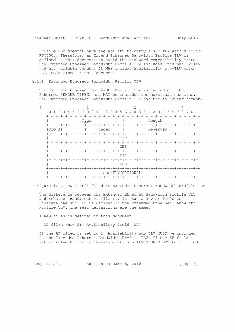
Internet-Draft RSVP-TE - Bandwidth Availability July 2015
Profile TLV doesn’t have the ability to carry a sub-TLV according to RFC6003. Therefore, an Extend Ethernet Bandwidth Profile TLV is defined in this document to avoid the backward compatibility issue. The Extended Ethernet Bandwidth Profile TLV includes Ethernet BW TLV and has variable length. It MAY include Availability sub-TLV which is also defined in this document.
3.1.1. Extended Ethernet Bandwidth Profile TLV
The Extended Ethernet Bandwidth Profile TLV is included in the Ethernet SENDER_TSPEC, and MAY be included for more than one time. The Extended Ethernet Bandwidth Profile TLV has the following format.
0 1 2 3 0 1 2 3 4 5 6 7 8 9 0 1 2 3 4 5 6 7 8 9 0 1 2 3 4 5 6 7 8 9 0 1 +-+-+-+-+-+-+-+-+-+-+-+-+-+-+-+-+-+-+-+-+-+-+-+-+-+-+-+-+-+-+-+-+ | Type | Length | +-+-+-+-+-+-+-+-+-+-+-+-+-+-+-+-+-+-+-+-+-+-+-+-+-+-+-+-+-+-+-+-+ |Pro|A| | Index | Reserved | +-+-+-+-+-+-+-+-+-+-+-+-+-+-+-+-+-+-+-+-+-+-+-+-+-+-+-+-+-+-+-+-+ | CIR | +-+-+-+-+-+-+-+-+-+-+-+-+-+-+-+-+-+-+-+-+-+-+-+-+-+-+-+-+-+-+-+-+ | CBS | +-+-+-+-+-+-+-+-+-+-+-+-+-+-+-+-+-+-+-+-+-+-+-+-+-+-+-+-+-+-+-+-+ | EIR | +-+-+-+-+-+-+-+-+-+-+-+-+-+-+-+-+-+-+-+-+-+-+-+-+-+-+-+-+-+-+-+-+ | EBS | +-+-+-+-+-+-+-+-+-+-+-+-+-+-+-+-+-+-+-+-+-+-+-+-+-+-+-+-+-+-+-+-+ | sub-TLV(OPTIONAL) | +-+-+-+-+-+-+-+-+-+-+-+-+-+-+-+-+-+-+-+-+-+-+-+-+-+-+-+-+-+-+-+-+
Figure 1: A new ’’AF’’ filed in Extended Ethernet Bandwidth Profile TLV
The difference between the Extended Ethernet Bandwidth Profile TLV and Ethernet Bandwidth Profile TLV is that a new AF field to indicate the sub-TLV is defined in the Extended Ethernet Bandwidth Profile TLV. The rest definitions are the same.
A new filed is defined in this document:
AF filed (bit 2): Availability Field (AF)
If the AF filed is set to 1, Availability sub-TLV MUST be included in the Extended Ethernet Bandwidth Profile TLV. If the AF field is set to value 0, then an Availability sub-TLV SHOULD NOT be included.
Long, et al. Expires January 6, 2016 [Page 5]
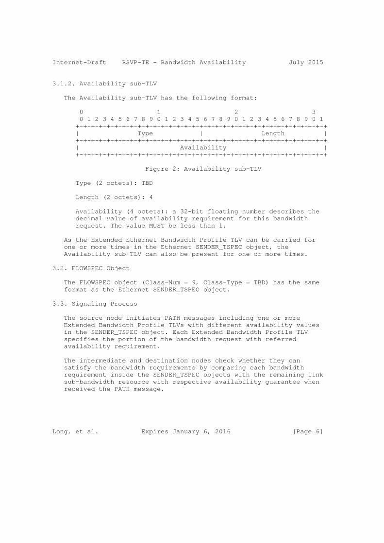
Internet-Draft RSVP-TE - Bandwidth Availability July 2015
3.1.2. Availability sub-TLV
The Availability sub-TLV has the following format:
0 1 2 3 0 1 2 3 4 5 6 7 8 9 0 1 2 3 4 5 6 7 8 9 0 1 2 3 4 5 6 7 8 9 0 1 +-+-+-+-+-+-+-+-+-+-+-+-+-+-+-+-+-+-+-+-+-+-+-+-+-+-+-+-+-+-+-+-+ | Type | Length | +-+-+-+-+-+-+-+-+-+-+-+-+-+-+-+-+-+-+-+-+-+-+-+-+-+-+-+-+-+-+-+-+ | Availability | +-+-+-+-+-+-+-+-+-+-+-+-+-+-+-+-+-+-+-+-+-+-+-+-+-+-+-+-+-+-+-+-+
Figure 2: Availability sub-TLV
Type (2 octets): TBD
Length (2 octets): 4
Availability (4 octets): a 32-bit floating number describes the decimal value of availability requirement for this bandwidth request. The value MUST be less than 1.
As the Extended Ethernet Bandwidth Profile TLV can be carried for one or more times in the Ethernet SENDER_TSPEC object, the Availability sub-TLV can also be present for one or more times.
3.2. FLOWSPEC Object
The FLOWSPEC object (Class-Num = 9, Class-Type = TBD) has the same format as the Ethernet SENDER_TSPEC object.
3.3. Signaling Process
The source node initiates PATH messages including one or more Extended Bandwidth Profile TLVs with different availability values in the SENDER_TSPEC object. Each Extended Bandwidth Profile TLV specifies the portion of the bandwidth request with referred availability requirement.
The intermediate and destination nodes check whether they can satisfy the bandwidth requirements by comparing each bandwidth requirement inside the SENDER_TSPEC objects with the remaining link sub-bandwidth resource with respective availability guarantee when received the PATH message.
Long, et al. Expires January 6, 2016 [Page 6]
Internet-Draft RSVP-TE - Bandwidth Availability July 2015
o If all <bandwidth, availability> requirements can be satisfied, it SHOULD reserve the bandwidth resource from each remaining sub-bandwidth portion to set up this LSP. Optionally, the higher availability bandwidth can be allocated to lower availability request when the lower availability bandwidth cannot satisfy the request.
o If at least one <bandwidth, availability> requirement cannot be satisfied, it SHOULD generate PathErr message with the error code "Admission Control Error" and the error value "Requested Bandwidth Unavailable" (see [RFC2205]).
If two LSPs request for the bandwidth with the same availability requirement, a way to resolve the contention is comparing the node ID, the node with the higher node ID will win the contention. More details can be found in [RFC3473].
If a node does not support the Extended Bandwidth Profile TLV and Availability sub-TLV, it SHOULD generate PathErr message with the error code "Extended Class-Type Error" and the error value "Class- Type mismatch" (see [RFC2205]).
4. Security Considerations
This document does not introduce new security considerations to the existing RSVP-TE signaling protocol.
5. IANA Considerations
IANA maintains registries and sub-registries for RSVP-TE used by GMPLS. IANA is requested to make allocations from these registries as set out in the following sections.
5.1 Ethernet Sender TSpec TLVs
IANA maintains a registry of GMPLS parameters called ’’Generalized Multi-Protocol Label Switching (GMPLS) Signaling Parameters’’.
IANA has created a new sub-registry called ’’Ethernet Sender TSpec TLVs / Ethernet Flowspec TLVs’’ to contain the TLV type values for TLVs carried in the Ethernet SENDER_TSPEC object. A new value is as follow:
Type Description Reference
Long, et al. Expires January 6, 2016 [Page 7]
Internet-Draft RSVP-TE - Bandwidth Availability July 2015
----- ----------------------------------- ---------
TBD Extended Ethernet Bandwidth Profile [This ID]
5.2 Extended Ethernet Bandwidth Profile TLV
IANA has created a new sub-registry called ’’Extended Ethernet Bandwidth Profiles’’ to contain bit flags carried in the Extended Ethernet Bandwidth Profile TLV of the Ethernet SENDER_TSPEC object.
Bits are to be allocated by Standards Action. Bits are numbered from bit 0 as the low order bit. A new bit field is as follow:
Bit Hex Description Reference
--- ---- ------------------ -----------
0 0x01 Coupling Flag (CF) [RFC6003]
1 0x02 Color Mode (CM) [RFC6003]
2 0x04 Availability Field (AF) [This ID]
Sub-TLV types for Extended Ethernet Bandwidth Profiles are to be allocated by Standards Action. Initial values are as follows:
Type Length Format Description
--- ---- ------------------ -----------
0 - Reserved Reserved value
0x01 4 see Section 3.1.2 of this ID Availability
6. References
6.1. Normative References
[RFC2210] Wroclawski, J., ’’The Use of RSVP with IETF Integrated Services’’, RFC 2210, September 1997.
[RFC3209] Awduche, D., Berger, L., Gan, D., Li, T., Srinivasan, V.,and G. Swallow, "RSVP-TE: Extensions to RSVP for LSP Tunnels", RFC 3209, December 2001.
Long, et al. Expires January 6, 2016 [Page 8]
Internet-Draft RSVP-TE - Bandwidth Availability July 2015
[RFC3473] Berger, L., "Generalized Multi-Protocol Label Switching (GMPLS) Signaling Resource ReserVation Protocol-Traffic Engineering (RSVP-TE) Extensions", RFC 3473, January 2003.
[RFC6003] Papadimitriou, D. ’’Ethernet Traffic Parameters’’, RFC 6003, October 2010.
[G.827] ITU-T Recommendation, ’’Availability performance parameters and objectives for end-to-end international constant bit- rate digital paths’’, September, 2003.
[F.1703] ITU-R Recommendation, ’’Availability objectives for real digital fixed wireless links used in 27 500 km hypothetical reference paths and connections’’, January, 2005.
[P.530] ITU-R Recommendation,’’ Propagation data and prediction methods required for the design of terrestrial line-of- sight systems’’, February, 2012
[EN 302 217] ETSI standard, ’’Fixed Radio Systems; Characteristics and requirements for point-to-point equipment and antennas’’, April, 2009
[ARTE] H., Long, M., Ye, Mirsky, G., Alessandro, A., Shah, H., ’’OSPF Routing Extension for Links with Variable Discrete Bandwidth’’, Work in Progress, February, 2014
6.2. Informative References
[MCOS] Minei, I., Gan, D., Kompella, K., and X. Li, "Extensions for Differentiated Services-aware Traffic Engineered LSPs", Work in Progress, June 2006.
7. Appendix: Bandwidth Availability Example
In mobile backhaul network, microwave links are very popular for providing connection of last hops. In case of heavy rain, to maintain the link connectivity, the microwave link MAY lower the modulation level since demodulating the lower modulation level needs a lower Signal-to-Noise Ratio (SNR). This is called adaptive modulation technology [EN 302 217]. However, a lower modulation level also means lower link bandwidth. When link bandwidth is reduced because of modulation down-shifting, high-priority traffic can be maintained, while lower-priority traffic is dropped. Similarly, the copper links MAY change their link bandwidth due to external interference.
Long, et al. Expires January 6, 2016 [Page 9]

Internet-Draft RSVP-TE - Bandwidth Availability July 2015
Presuming that a link has three discrete bandwidth levels:
The link bandwidth under modulation level 1, e.g., QPSK, is 100 Mbps;
The link bandwidth under modulation level 2, e.g., 16QAM, is 200 Mbps;
The link bandwidth under modulation level 3, e.g., 256QAM, is 400 Mbps.
In sunny day, the modulation level 3 can be used to achieve 400 Mbps link bandwidth.
A light rain with X mm/h rate triggers the system to change the modulation level from level 3 to level 2, with bandwidth changing from 400 Mbps to 200 Mbps. The probability of X mm/h rain in the local area is 52 minutes in a year. Then the dropped 200 Mbps bandwidth has 99.99% availability.
A heavy rain with Y(Y>X) mm/h rate triggers the system to change the modulation level from level 2 to level 1, with bandwidth changing from 200 Mbps to 100 Mbps. The probability of Y mm/h rain in the local area is 26 minutes in a year. Then the dropped 100 Mbps bandwidth has 99.995% availability.
For the 100M bandwidth of the modulation level 1, only the extreme weather condition can cause the whole system unavailable, which only happens for 5 minutes in a year. So the 100 Mbps bandwidth of the modulation level 1 owns the availability of 99.999%.
In a word, the maximum bandwidth is 400 Mbps. According to the weather condition, the sub-bandwidth and its availability are shown as follows:
Sub-bandwidth(Mbps) Availability
------------------ ------------
200 99.99%
100 99.995%
100 99.999%
Long, et al. Expires January 6, 2016 [Page 10]

Internet-Draft RSVP-TE - Bandwidth Availability July 2015
8. Acknowledgments
The authors would like to thank Khuzema Pithewan, Lou Berger, Yuji Tochio, Dieter Beller, and Autumn Liu for their comments on the document.
Authors’ Addresses
Long, et al. Expires January 6, 2016 [Page 11]
Internet-Draft RSVP-TE - Bandwidth Availability July 2015
Hao Long Huawei Technologies Co., Ltd. No.1899, Xiyuan Avenue, Hi-tech Western District Chengdu 611731, P.R.China
Phone: +86-18615778750 Email: [email protected]
Min Ye (editor) Huawei Technologies Co., Ltd. No.1899, Xiyuan Avenue, Hi-tech Western District Chengdu 611731, P.R.China
Email: [email protected]
Greg Mirsky (editor) Ericsson
Email: [email protected]
Alessandro D’Alessandro Telecom Italia S.p.A
Email: [email protected]
Himanshu Shah Ciena Corp. 3939 North First Street San Jose, CA 95134 US
Email: [email protected]
Long, et al. Expires January 6, 2016 [Page 12]


Network Working Group Y. Lee (Editor) D. DhodyInternet Draft HuaweiIntended status: Standard Track A. GuoExpires: January 2016 ADVA
V. Lopez Telefonica
D. King U. of Lancaster
July 1, 2015
A Yang Data Model for WSON Optical Networks
draft-lee-ccamp-wson-yang-02
Abstract
This document provides a YANG data model for the routing and wavelength assignment (RWA) TE topology in wavelength switched optical networks (WSONs).
Status of this Memo
This Internet-Draft is submitted to IETF in full conformance with the provisions of BCP 78 and BCP 79.
Internet-Drafts are working documents of the Internet Engineering Task Force (IETF), its areas, and its working groups. Note that other groups may also distribute working documents as Internet- Drafts.
Internet-Drafts are draft documents valid for a maximum of six months and may be updated, replaced, or obsoleted by other documents at any time. It is inappropriate to use Internet-Drafts as reference material or to cite them other than as "work in progress."
The list of current Internet-Drafts can be accessed at http://www.ietf.org/ietf/1id-abstracts.txt
Lee Expires January 1, 2016 [Page 1]
Internet-Draft WSON YANG Model July 2015
The list of Internet-Draft Shadow Directories can be accessed at http://www.ietf.org/shadow.html
This Internet-Draft will expire on January 1, 2016.
Copyright Notice
Copyright (c) 2015 IETF Trust and the persons identified as the document authors. All rights reserved.
This document is subject to BCP 78 and the IETF Trust’s Legal Provisions Relating to IETF Documents (http://trustee.ietf.org/license-info) in effect on the date of publication of this document. Please review these documents carefully, as they describe your rights and restrictions with respect to this document. Code Components extracted from this document must include Simplified BSD License text as described in Section 4.e of the Trust Legal Provisions and are provided without warranty as described in the Simplified BSD License.
Table of Contents
1. Introduction...................................................3 2. Routing and Wavelength Assignment Informational Model..........3 2.1. Connectivity Matrix Model.................................3 2.2. Resource Pool Model.......................................4 2.3. Port Label Restriction Model..............................8 2.4. Wavelength Availability on Links..........................9 3. YANG Model (Tree Structure)...................................10 4. WSON-RWA YANG Model...........................................11 5. Security Considerations.......................................17 6. IANA Considerations...........................................17 7. Acknowledgments...............................................17 8. References....................................................18 8.1. Normative References.....................................18 8.2. Informative References...................................18 9. Contributors..................................................18 Authors’ Addresses...............................................18
Lee Expires January 1, 2016 [Page 2]
Internet-Draft WSON YANG Model July 2015
1. Introduction
This document provides a YANG data model for the routing and wavelength assignment (RWA) Traffic Engineering (TE) topology in wavelength switched optical networks (WSONs). The YANG model described in this document is a WSON technology-specific Yang model based on the information model developed in [RFC7446] and the two encoding drafts [WSON-Encode] and [Gen-Encode] that developed protocol independent encodings based on [RFC7446]. This document augments the generic TE topology draft [TE-TOPO].
What is not in scope of this document is both impairment-aware WSON and flex-grid.
2. Routing and Wavelength Assignment Informational Model
The relevant information model in this document comprises
- Connectivity Matrix Model (Section 2.1) - Resource Pool Model (Section 2.2) - Port Wavelength Restriction (Section 2.3) - Wavelength Availability on Links (Section 2.4)
[Editor’s Note: This version covers the corresponding YANG data model for the first two sections (Sections 2.1 and 2.2) and leaves the YANG model for Sections 2.3 and 2.4 in the later version.]
Sections 2.1 - 2.4 rehashes key information models from [RWA-Info] to facilitate the development of the YANG model (Section 3).
2.1. Connectivity Matrix Model
The connectivity matrix (ConnectivityMatrix) represents either the potential connectivity matrix for asymmetric switches (e.g. ROADMs and such) or fixed connectivity for an asymmetric device such as a multiplexer.
Note that multiple connectivity matrices are allowed and the Node_ID would be an appropriate identifier for the node to point the Connectivity matrix within the WSON RWA context.
<Node_Information> ::= <Node_ID> [<ConnectivityMatrix>...]
<ConnectivityMatrix> ::= <MatrixID>
<ConnType>
Lee Expires January 1, 2016 [Page 3]

Internet-Draft WSON YANG Model July 2015
<Matrix>
Where
<MatrixID> is a unique identifier for the matrix.
<ConnType> can be either 0 or 1 depending upon whether the connectivity is either fixed or switched.
<Matrix> represents the fixed or switched connectivity in that Matrix(i, j) = 0 or 1 depending on whether input port i can connect to output port j for one or more wavelengths.
2.2. Resource Pool Model
A WSON node may include regenerators or wavelength converters arranged in a shared pool. As discussed in [RFC6163] this can include Optical-Electronic-Optical (OEO) based Wavelength Division Multiplexing (WDM) switches as well. There are a number of different approaches used in the design of WDM switches containing regenerator or converter pools. However, from the point of view of path computation the following need to be known:
1. The nodes that support regeneration or wavelength conversion.
2. The accessibility and availability of a wavelength converter to convert from a given input wavelength on a particular input port to a desired output wavelength on a particular output port.
3. Limitations on the types of signals that can be converted and the conversions that can be performed.
The following Figures show resource pool architecture of WSON.
Lee Expires January 1, 2016 [Page 4]
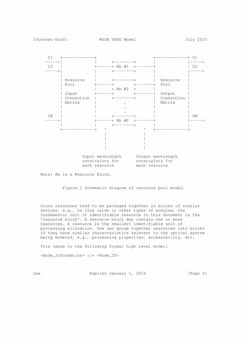
Internet-Draft WSON YANG Model July 2015
I1 +-------------+ +-------------+ O1 ----->| | +--------+ | |-----> I2 | +------+ Rb #1 +-------+ | O2 ----->| | +--------+ | |-----> | | | | | Resource | +--------+ | Resource | | Pool +------+ +-------+ Pool | | | + Rb #2 + | | | Input +------+ +-------| Output | | Connection | +--------+ | Connection | | Matrix | . | Matrix | | | . | | | | . | | IN | | +--------+ | | OM ----->| +------+ Rb #P +-------+ |-----> | | +--------+ | | +-------------+ ^ ^ +-------------+ | | | | | | | |
Input wavelength Output wavelength constraints for constraints for each resource each resource
Note: Rb is a Resource Block.
Figure 1 Schematic diagram of resource pool model.
Since resources tend to be packaged together in blocks of similar devices, e.g., on line cards or other types of modules, the fundamental unit of identifiable resource in this document is the "resource block". A resource block may contain one or more resources. A resource is the smallest identifiable unit of processing allocation. One can group together resources into blocks if they have similar characteristics relevant to the optical system being modeled, e.g., processing properties, accessibility, etc.
This leads to the following formal high level model:
<Node_Information> ::= <Node_ID>
Lee Expires January 1, 2016 [Page 5]

Internet-Draft WSON YANG Model July 2015
[<ConnectivityMatrix>...]
[<ResourcePool>]
Where
<ResourcePool> ::= <ResourceBlockInfo>...
[<ResourceAccessibility>...]
[<ResourceWaveConstraints>...]
[<RBPoolState>]
<ResourceAccessibility> ::= <PoolInputMatrix>
<PoolOutputMatrix>
<ResourceWaveConstraints> ::= <InputWaveConstraints>
<OutputOutputWaveConstraints>
<RBSharedAccessWaveAvailability> ::= [<InAvailableWavelengths>]
[<OutAvailableWavelengths>]
<RBPoolState> ::= <ResourceBlockID>
<NumResourcesInUse>
[<RBSharedAccessWaveAvailability>]
[<RBPoolState>]
<ResourceBlockInfo> ::= <ResourceBlockSet>
Lee Expires January 1, 2016 [Page 6]
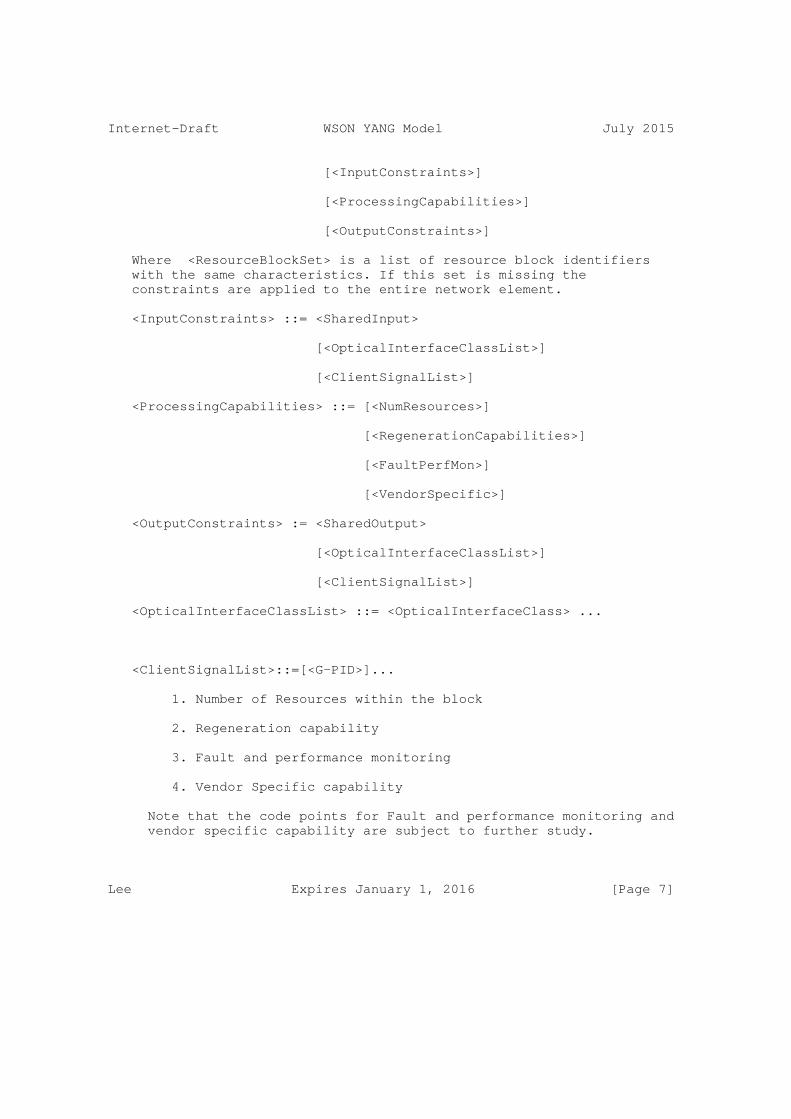
Internet-Draft WSON YANG Model July 2015
[<InputConstraints>]
[<ProcessingCapabilities>]
[<OutputConstraints>]
Where <ResourceBlockSet> is a list of resource block identifiers with the same characteristics. If this set is missing the constraints are applied to the entire network element.
<InputConstraints> ::= <SharedInput>
[<OpticalInterfaceClassList>]
[<ClientSignalList>]
<ProcessingCapabilities> ::= [<NumResources>]
[<RegenerationCapabilities>]
[<FaultPerfMon>]
[<VendorSpecific>]
<OutputConstraints> := <SharedOutput>
[<OpticalInterfaceClassList>]
[<ClientSignalList>]
<OpticalInterfaceClassList> ::= <OpticalInterfaceClass> ...
<ClientSignalList>::=[<G-PID>]...
1. Number of Resources within the block
2. Regeneration capability
3. Fault and performance monitoring
4. Vendor Specific capability
Note that the code points for Fault and performance monitoring and vendor specific capability are subject to further study.
Lee Expires January 1, 2016 [Page 7]
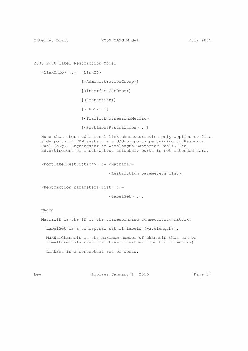
Internet-Draft WSON YANG Model July 2015
2.3. Port Label Restriction Model
<LinkInfo> ::= <LinkID>
[<AdministrativeGroup>]
[<InterfaceCapDesc>]
[<Protection>]
[<SRLG>...]
[<TrafficEngineeringMetric>]
[<PortLabelRestriction>...]
Note that these additional link characteristics only applies to line side ports of WDM system or add/drop ports pertaining to Resource Pool (e.g., Regenerator or Wavelength Converter Pool). The advertisement of input/output tributary ports is not intended here.
<PortLabelRestriction> ::= <MatrixID>
<Restriction parameters list>
<Restriction parameters list> ::=
<LabelSet> ...
Where
MatrixID is the ID of the corresponding connectivity matrix.
LabelSet is a conceptual set of labels (wavelengths).
MaxNumChannels is the maximum number of channels that can be simultaneously used (relative to either a port or a matrix).
LinkSet is a conceptual set of ports.
Lee Expires January 1, 2016 [Page 8]

Internet-Draft WSON YANG Model July 2015
2.4. Wavelength Availability on Links
In the previously presented information model there are a limited number of information elements that are dynamic, i.e., subject to change with subsequent establishment and teardown of connections. Depending on the protocol used to convey this overall information model it may be possible to send this dynamic information separate from the relatively larger amount of static information needed to characterize WSON’s and their network elements.
<DynamicLinkInfo> ::= <LinkID>
<AvailableLabels>
[<SharedBackupLabels>]
AvailableLabels is a set of labels (wavelengths) currently available on the link. Given this information and the port wavelength restrictions one can also determine which wavelengths are currently in use. This parameter could potential be used with other technologies that GMPLS currently covers or may cover in the future.
SharedBackupLabels is a set of labels (wavelengths) currently used for shared backup protection on the link. An example usage of this information in a WSON setting is given in [Shared]. This parameter could potential be used with other technologies that GMPLS currently covers or may cover in the future.
Lee Expires January 1, 2016 [Page 9]
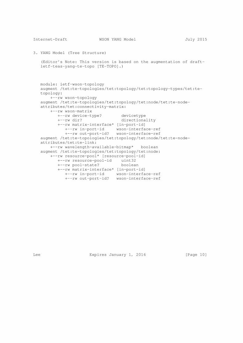
Internet-Draft WSON YANG Model July 2015
3. YANG Model (Tree Structure)
(Editor’s Note: This version is based on the augmentation of draft- ietf-teas-yang-te-topo [TE-TOPO].)
module: ietf-wson-topology augment /tet:te-topologies/tet:topology/tet:topology-types/tet:te- topology: +--rw wson-topology augment /tet:te-topologies/tet:topology/tet:node/tet:te-node- attributes/tet:connectivity-matrix: +--rw wson-matrix +--rw device-type? devicetype +--rw dir? directionality +--rw matrix-interface* [in-port-id] +--rw in-port-id wson-interface-ref +--rw out-port-id? wson-interface-ref augment /tet:te-topologies/tet:topology/tet:node/tet:te-node- attributes/tet:te-link: +--rw wavelength-available-bitmap* boolean augment /tet:te-topologies/tet:topology/tet:node: +--rw resource-pool* [resource-pool-id] +--rw resource-pool-id uint32 +--rw pool-state? boolean +--rw matrix-interface* [in-port-id] +--rw in-port-id wson-interface-ref +--rw out-port-id? wson-interface-ref
Lee Expires January 1, 2016 [Page 10]
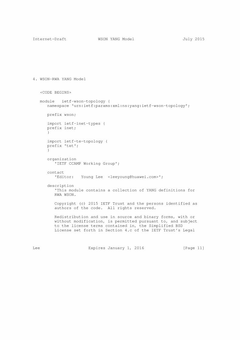
Internet-Draft WSON YANG Model July 2015
4. WSON-RWA YANG Model
<CODE BEGINS>
module ietf-wson-topology { namespace "urn:ietf:params:xml:ns:yang:ietf-wson-topology";
prefix wson;
import ietf-inet-types { prefix inet; }
import ietf-te-topology { prefix "tet"; }
organization "IETF CCAMP Working Group";
contact "Editor: Young Lee <[email protected]>";
description "This module contains a collection of YANG definitions for RWA WSON.
Copyright (c) 2015 IETF Trust and the persons identified as authors of the code. All rights reserved.
Redistribution and use in source and binary forms, with or without modification, is permitted pursuant to, and subject to the license terms contained in, the Simplified BSD License set forth in Section 4.c of the IETF Trust’s Legal
Lee Expires January 1, 2016 [Page 11]
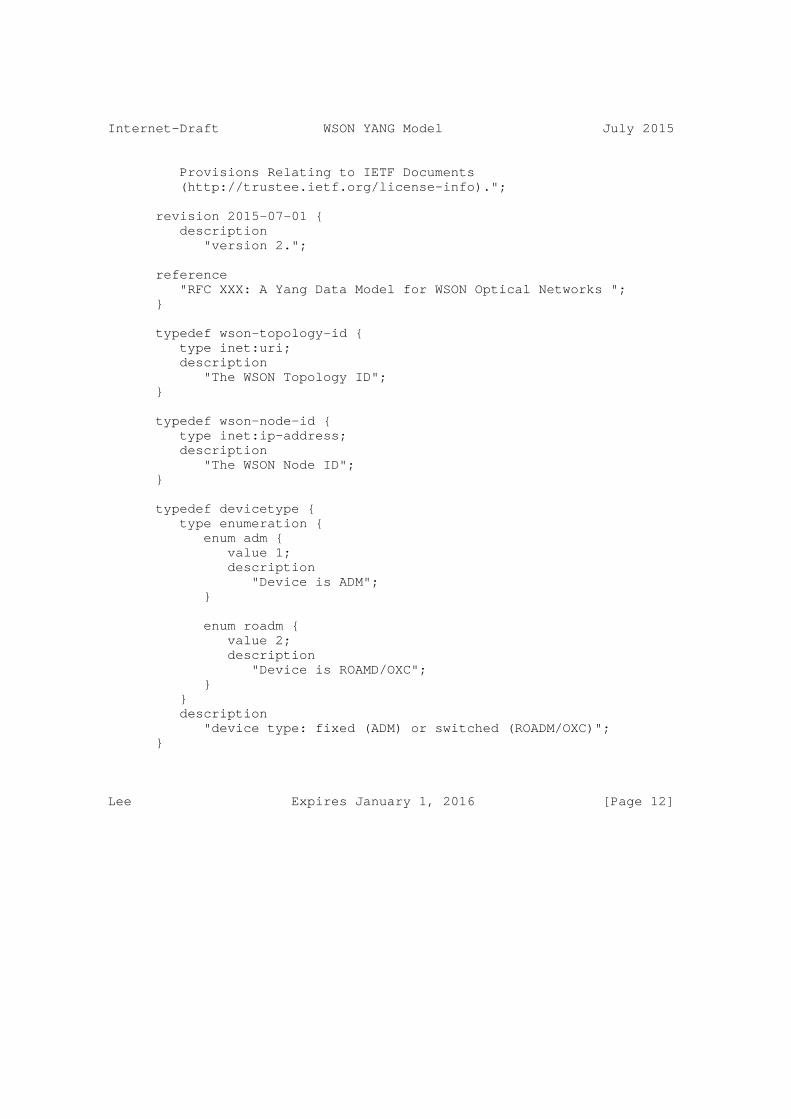
Internet-Draft WSON YANG Model July 2015
Provisions Relating to IETF Documents (http://trustee.ietf.org/license-info).";
revision 2015-07-01 { description "version 2.";
reference "RFC XXX: A Yang Data Model for WSON Optical Networks "; }
typedef wson-topology-id { type inet:uri; description "The WSON Topology ID"; }
typedef wson-node-id { type inet:ip-address; description "The WSON Node ID"; }
typedef devicetype { type enumeration { enum adm { value 1; description "Device is ADM"; }
enum roadm { value 2; description "Device is ROAMD/OXC"; } } description "device type: fixed (ADM) or switched (ROADM/OXC)"; }
Lee Expires January 1, 2016 [Page 12]
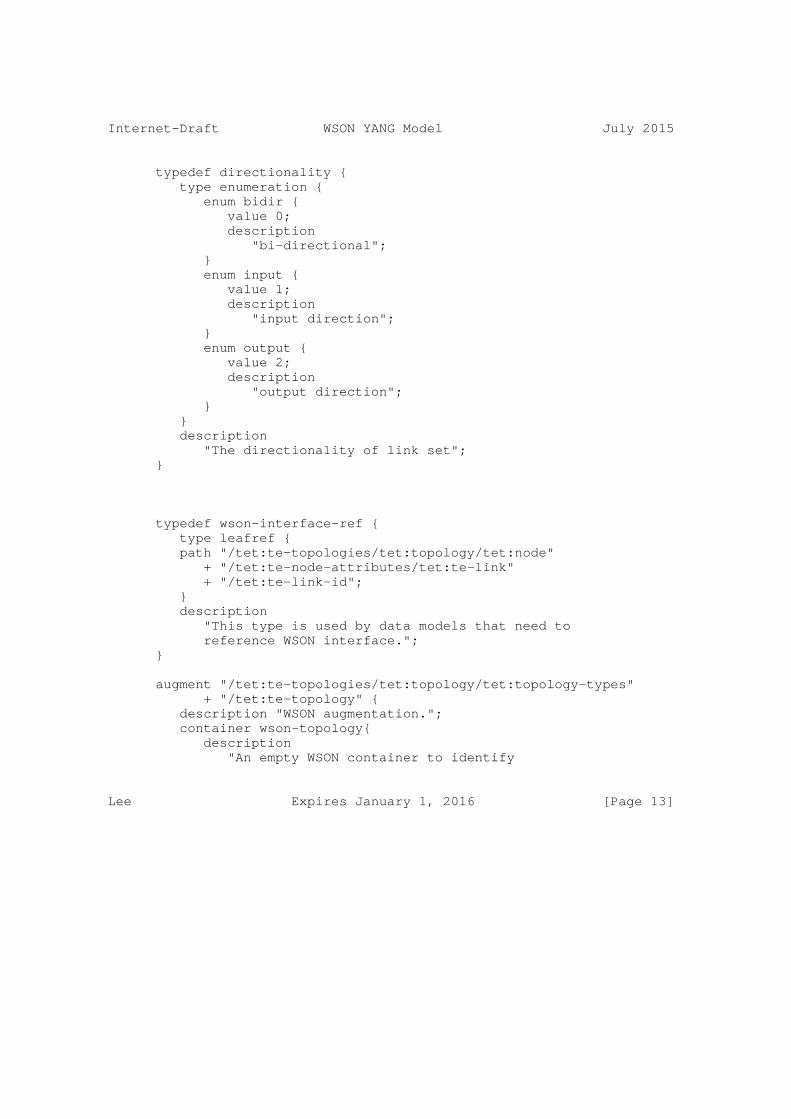
Internet-Draft WSON YANG Model July 2015
typedef directionality { type enumeration { enum bidir { value 0; description "bi-directional"; } enum input { value 1; description "input direction"; } enum output { value 2; description "output direction"; } } description "The directionality of link set"; }
typedef wson-interface-ref { type leafref { path "/tet:te-topologies/tet:topology/tet:node" + "/tet:te-node-attributes/tet:te-link" + "/tet:te-link-id"; } description "This type is used by data models that need to reference WSON interface."; }
augment "/tet:te-topologies/tet:topology/tet:topology-types" + "/tet:te-topology" { description "WSON augmentation."; container wson-topology{ description "An empty WSON container to identify
Lee Expires January 1, 2016 [Page 13]
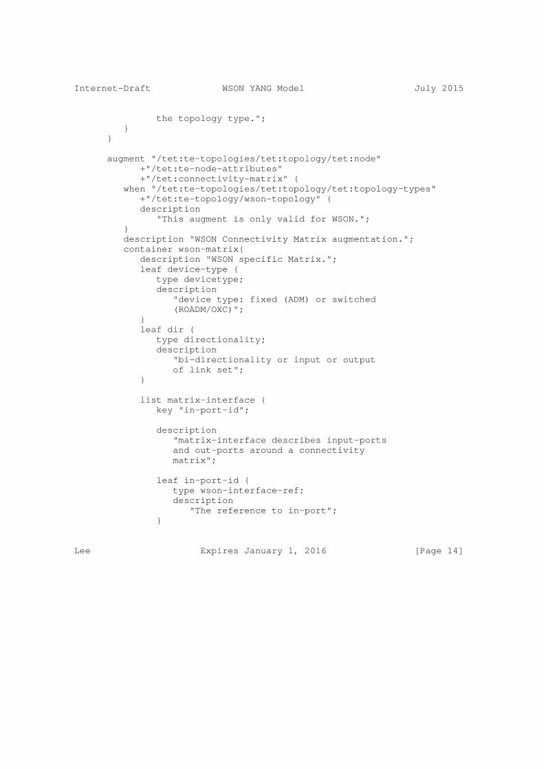
Internet-Draft WSON YANG Model July 2015
the topology type."; } }
augment "/tet:te-topologies/tet:topology/tet:node" +"/tet:te-node-attributes" +"/tet:connectivity-matrix" { when "/tet:te-topologies/tet:topology/tet:topology-types" +"/tet:te-topology/wson-topology" { description "This augment is only valid for WSON."; } description "WSON Connectivity Matrix augmentation."; container wson-matrix{ description "WSON specific Matrix."; leaf device-type { type devicetype; description "device type: fixed (ADM) or switched (ROADM/OXC)"; } leaf dir { type directionality; description "bi-directionality or input or output of link set"; }
list matrix-interface { key "in-port-id";
description "matrix-interface describes input-ports and out-ports around a connectivity matrix";
leaf in-port-id { type wson-interface-ref; description "The reference to in-port"; }
Lee Expires January 1, 2016 [Page 14]
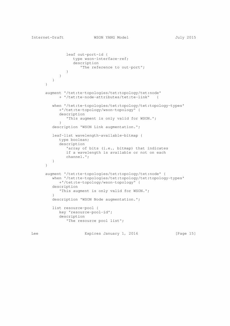
Internet-Draft WSON YANG Model July 2015
leaf out-port-id { type wson-interface-ref; description "The reference to out-port"; } } } }
augment "/tet:te-topologies/tet:topology/tet:node" + "/tet:te-node-attributes/tet:te-link" {
when "/tet:te-topologies/tet:topology/tet:topology-types" +"/tet:te-topology/wson-topology" { description "This augment is only valid for WSON."; } description "WSON Link augmentation.";
leaf-list wavelength-available-bitmap { type boolean; description "array of bits (i.e., bitmap) that indicates if a wavelength is available or not on each channel."; } }
augment "/tet:te-topologies/tet:topology/tet:node" { when "/tet:te-topologies/tet:topology/tet:topology-types" +"/tet:te-topology/wson-topology" { description "This augment is only valid for WSON."; } description "WSON Node augmentation.";
list resource-pool { key "resource-pool-id"; description "The resource pool list";
Lee Expires January 1, 2016 [Page 15]
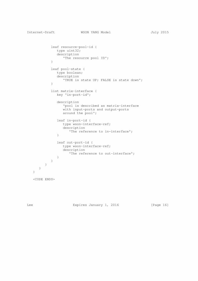
Internet-Draft WSON YANG Model July 2015
leaf resource-pool-id { type uint32; description "The resource pool ID"; }
leaf pool-state { type boolean; description "TRUE is state UP; FALSE is state down"; }
list matrix-interface { key "in-port-id";
description "pool is described as matrix-interface with input-ports and output-ports around the pool";
leaf in-port-id { type wson-interface-ref; description "The reference to in-interface"; }
leaf out-port-id { type wson-interface-ref; description "The reference to out-interface"; } } } } }
<CODE ENDS>
Lee Expires January 1, 2016 [Page 16]

Internet-Draft WSON YANG Model July 2015
5. Security Considerations
TDB
6. IANA Considerations
TDB
7. Acknowledgments
This document was prepared using 2-Word-v2.0.template.dot.
Lee Expires January 1, 2016 [Page 17]
Internet-Draft WSON YANG Model July 2015
8. References
8.1. Normative References
[RFC7446] Y. Lee, G. Bernstein, D. Li, W. Imajuku, "Routing and Wavelength Assignment Information Model for Wavelength Switched Optical Networks", RFC 7446, Feburary 2015.
[Gen-Encode] G. Bernstein, Y. Lee, D. Li, W. Imajuku, "General Network Element Constraint Encoding for GMPLS Controlled Networks", work in progress: draft-ietf-ccamp-general- constraint-encode.
[WSON-Encode] G. Bernstein, Y. Lee, D. Li, W. Imajuku, "Routing and Wavelength Assignment Information Encoding for Wavelength Switched Optical Networks", work in progress: draft-ietf- ccamp-rwa-wson-encode.
[TE-TOPO] X. Liu, et al., "YANG Data Model for TE Topologies", work in progress: draft-ietf-teas-yang-te-topo.
8.2. Informative References
9. Contributors
Xian Zhang Huawei Technologies Email: [email protected]
Authors’ Addresses
Young Lee (ed.) Huawei Technologies 5340 Legacy Drive, Building 3 Plano, TX 75023 USA
Phone: (469) 277-5838 Email: [email protected]
Lee Expires January 1, 2016 [Page 18]
Internet-Draft WSON YANG Model July 2015
Dhruv Dhody Huawei Technologies India Pvt. Ltd, Near EPIP Industrial Area, Kundalahalli Village, Whitefield, Bangalore - 560 037 [H1-2A-245]
Email: [email protected]
Aihua Guo ADVA Email: [email protected]
Victor Lopez Telefonica Email: [email protected]
Daniel King University of Lancaster Email: [email protected]
Lee Expires January 1, 2016 [Page 19]