Embed Size (px)
Citation preview
International Towing Tank ConferenceITTC Symbols and Terminology List
Beta Version 1996for general discussion
Please go to next page for hypertext table of contents
Prepared by the 21st ITTC Symbols and Terminology GroupHypertext Beta Version 1996
Edited and Produced by Bruce JohnsonU.S. Naval Academy
Annapolis, MD 21402-5042, USAPhone +1 410-293-6457, Fax +1-410-293-2219
Based on the SaT List Version 1993Edited and Produced by Michael Schmiechen
Versuchsanstalt für Wasserbau und Schiffbau, Berlin: VWS, Mitteilungen, Heft 57 (1993)Mueller-Breslau-Strasse (Schleuseninsel)
D-10623 Berlin, Germany Phone +49-30-311 84-270, Fax +49-30-311 84-200
Please send or fax comments, suggestions, needed additions and clarificationsto one of the preparers listed above
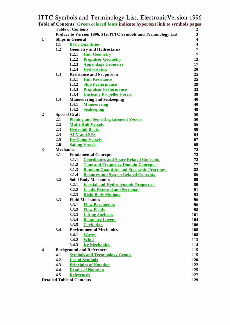
ITTC Symbols and Terminology List, ElectronicVersion 1996Table of Contents: Green colored fonts indicate hypertext link to symbols pages
Table of Contents 2Preface to Version 1996, 21st ITTC Symbols and Terminology List 3
1 Ships in General 41.1 Basic Quantities 41.2 Geometry and Hydrostatics 7
1.2.1 Hull Geometry 71.2.2 Propulsor Geometry 131.2.3 Appendage Geometry 171.2.4 Hydrostatics 20
1.3 Resistance and Propulsion 251.3.1 Hull Resistance 251.3.2 Ship Performance 291.3.3 Propulsor Performance 331.3.4 Unsteady Propeller Forces 38
1.4 Manoeuvring and Seakeeping 401.4.1 Manoeuvring 401.4.2 Seakeeping 48
2 Special Craft 502.1 Planing and Semi-Displacement Vessels 502.2 Multi-Hull Vessels 562.3 Hydrofoil Boats 592.4 ACV and SES 642.5 Ice Going Vessels 672.6 Sailing Vessels 69
3 Mechanics 723.1 Fundamental Concepts 72
3.1.1 Coordinates and Space Related Concepts 723.1.2 Time and Frequency Domain Concepts 773.1.3 Random Quantities and Stochastic Processes 823.1.4 Balances and System Related Concepts 86
3.2 Solid Body Mechanics 893.2.1 Inertial and Hydrodynamic Properties 893.2.2 Loads, External and Sectional 913.2.3 Rigid Body Motions 93
3.3 Fluid Mechanics 963.3.1 Flow Parameters 963.3.2 Flow Fields 983.3.3 Lifting Surfaces 1013.3.4 Boundary Layers 1043.3.5 Cavitation 106
3.4 Environmental Mechanics 1083.4.1 Waves 108
3.4.2 Wind 1133.4.3 Ice Mechanics 114
4 Background and References 1154.1 Symbols and Terminology Group 1154.2 List of Symbols 1204.3 Principles of Notation 1224.4 Details of Notation 1254.5 References 127
Detailed Table of Contents 129
ITTC Symbols Preface
Version 1996 3
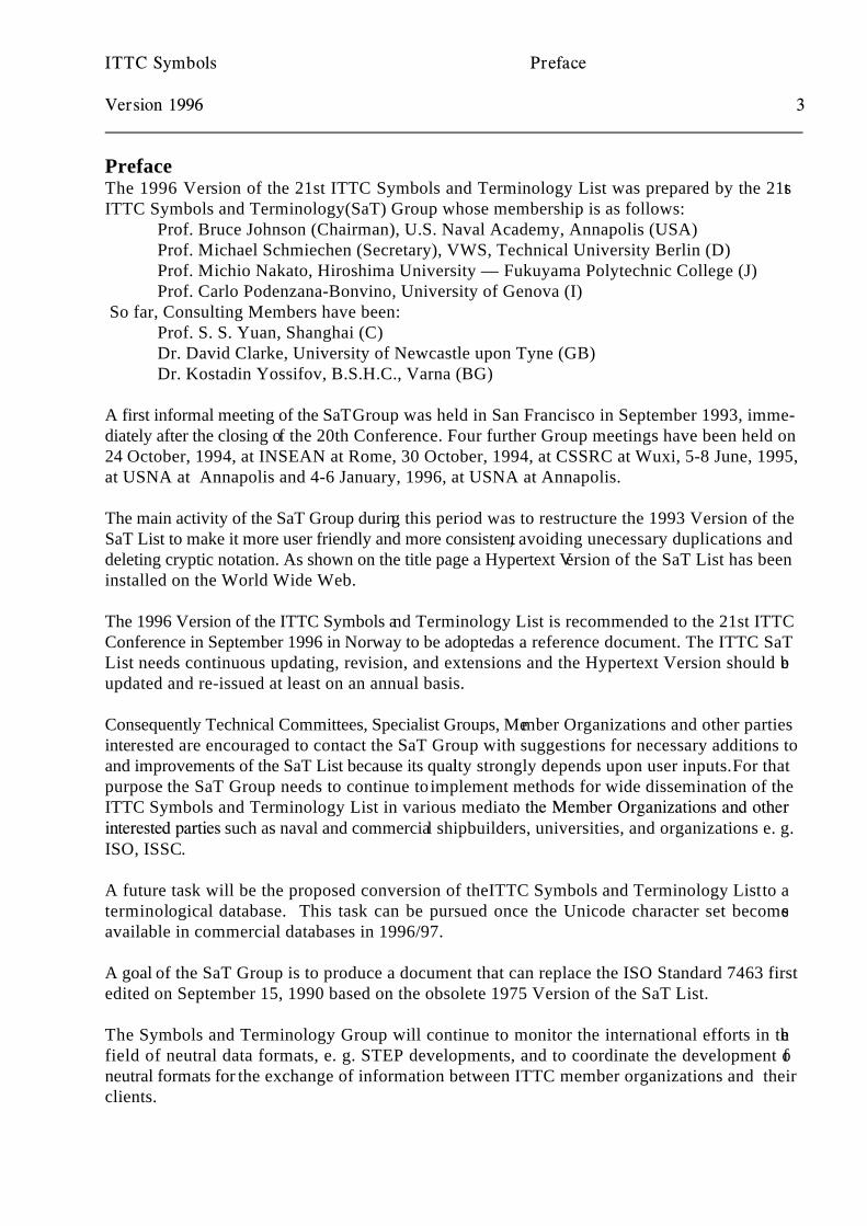
PrefaceThe 1996 Version of the 21st ITTC Symbols and Terminology List was prepared by the 21stITTC Symbols and Terminology(SaT) Group whose membership is as follows:
Prof. Bruce Johnson (Chairman), U.S. Naval Academy, Annapolis (USA)Prof. Michael Schmiechen (Secretary), VWS, Technical University Berlin (D)Prof. Michio Nakato, Hiroshima University — Fukuyama Polytechnic College (J)Prof. Carlo Podenzana-Bonvino, University of Genova (I)
So far, Consulting Members have been:Prof. S. S. Yuan, Shanghai (C)Dr. David Clarke, University of Newcastle upon Tyne (GB)Dr. Kostadin Yossifov, B.S.H.C., Varna (BG)
A first informal meeting of the SaT Group was held in San Francisco in September 1993, imme-diately after the closing of the 20th Conference. Four further Group meetings have been held on24 October, 1994, at INSEAN at Rome, 30 October, 1994, at CSSRC at Wuxi, 5-8 June, 1995,at USNA at Annapolis and 4-6 January, 1996, at USNA at Annapolis.
The main activity of the SaT Group during this period was to restructure the 1993 Version of theSaT List to make it more user friendly and more consistent, avoiding unecessary duplications anddeleting cryptic notation. As shown on the title page a Hypertext Version of the SaT List has beeninstalled on the World Wide Web.
The 1996 Version of the ITTC Symbols and Terminology List is recommended to the 21st ITTCConference in September 1996 in Norway to be adopted as a reference document. The ITTC SaTList needs continuous updating, revision, and extensions and the Hypertext Version should beupdated and re-issued at least on an annual basis.
Consequently Technical Committees, Specialist Groups, Member Organizations and other partiesinterested are encouraged to contact the SaT Group with suggestions for necessary additions toand improvements of the SaT List because its quality strongly depends upon user inputs. For thatpurpose the SaT Group needs to continue to implement methods for wide dissemination of theITTC Symbols and Terminology List in various media to the Member Organizations and otherinterested parties such as naval and commercial shipbuilders, universities, and organizations e. g.ISO, ISSC.
A future task will be the proposed conversion of the ITTC Symbols and Terminology List to aterminological database. This task can be pursued once the Unicode character set becomesavailable in commercial databases in 1996/97.
A goal of the SaT Group is to produce a document that can replace the ISO Standard 7463 firstedited on September 15, 1990 based on the obsolete 1975 Version of the SaT List.
The Symbols and Terminology Group will continue to monitor the international efforts in thefield of neutral data formats, e. g. STEP developments, and to coordinate the development ofneutral formats for the exchange of information between ITTC member organizations and theirclients.
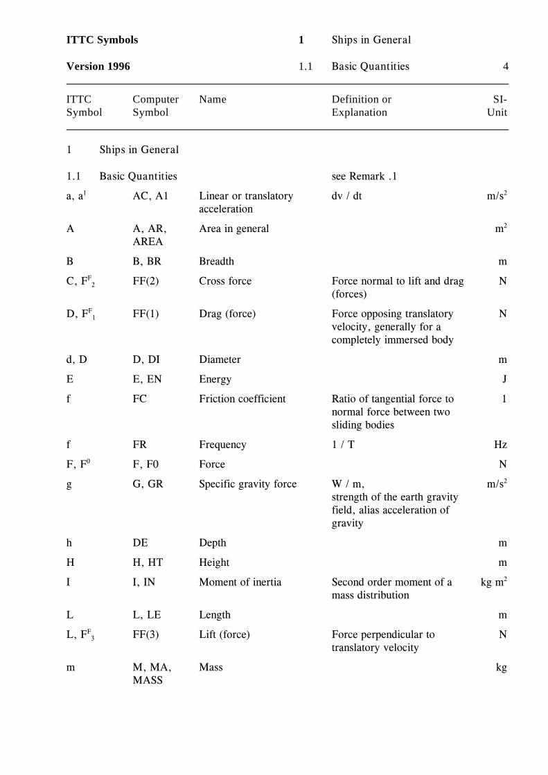
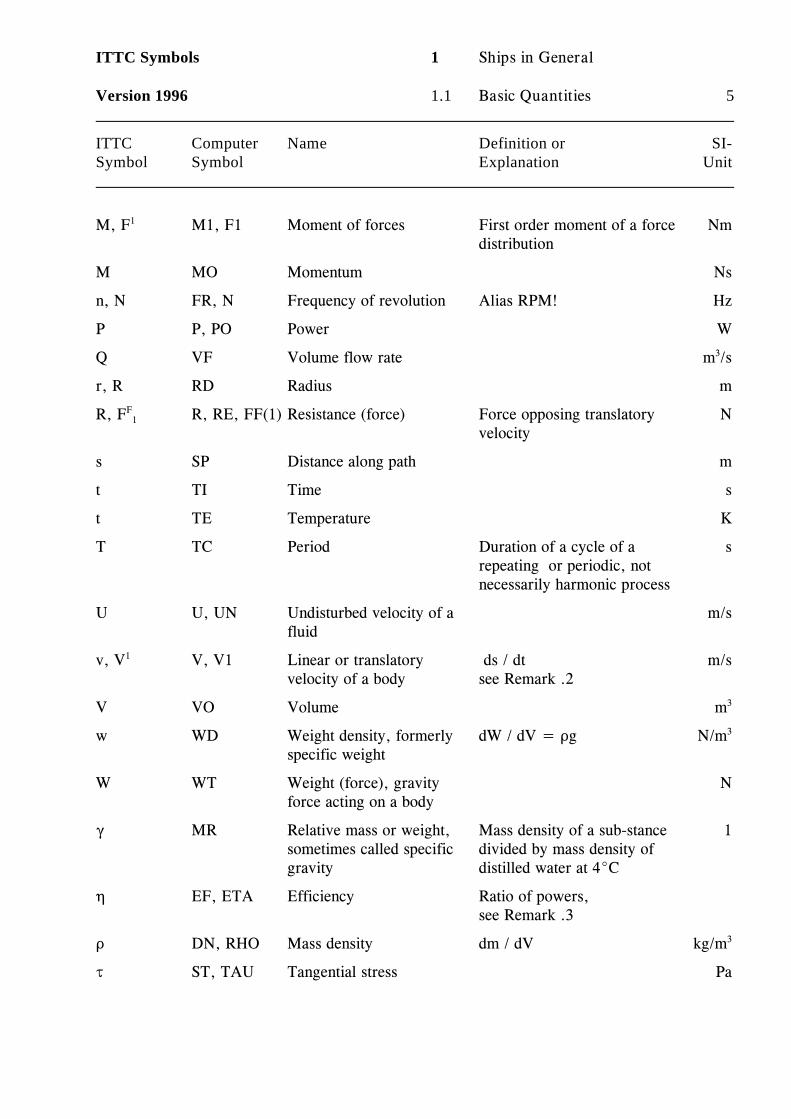
ITTC Symbols 1 Ships in General
Version 1996 1.1 Basic Quantities 4
ITTC Computer Name Definition or SI-Symbol Symbol Explanation Unit
1 Ships in General
1.1 Basic Quantities see Remark .1
a, a AC, A1 Linear or translatory dv / dt m/s1
acceleration
2
A A, AR, Area in general mAREA
2
B B, BR Breadth m
C, F FF(2) Cross force Force normal to lift and drag NF2
(forces)
D, F FF(1) Drag (force) Force opposing translatory NF1
velocity, generally for acompletely immersed body
d, D D, DI Diameter m
E E, EN Energy J
f FC Friction coefficient Ratio of tangential force to 1normal force between twosliding bodies
f FR Frequency 1 / T Hz
F, F F, F0 Force N0
g G, GR Specific gravity force W / m, m/sstrength of the earth gravityfield, alias acceleration ofgravity
2
h DE Depth m
H H, HT Height m
I I, IN Moment of inertia Second order moment of a kg mmass distribution
2
L L, LE Length m
L, F FF(3) Lift (force) Force perpendicular to NF3
translatory velocity
m M, MA, Mass kgMASS
ITTC Symbols 1 Ships in General
Version 1996 1.1 Basic Quantities 5
ITTC Computer Name Definition or SI-Symbol Symbol Explanation Unit
M, F M1, F1 Moment of forces First order moment of a force Nm1
distribution
M MO Momentum Ns
n, N FR, N Frequency of revolution Alias RPM! Hz
P P, PO Power W
Q VF Volume flow rate m /s3
r, R RD Radius m
R, F R, RE, FF(1) Resistance (force) Force opposing translatory NF1
velocity
s SP Distance along path m
t TI Time s
t TE Temperature K
T TC Period Duration of a cycle of a srepeating or periodic, notnecessarily harmonic process
U U, UN Undisturbed velocity of a m/sfluid
v, V V, V1 Linear or translatory ds / dt m/s1
velocity of a body see Remark .2
V VO Volume m3
w WD Weight density, formerly dW / dV = Dg N/mspecific weight
3
W WT Weight (force), gravity Nforce acting on a body
( MR Relative mass or weight, Mass density of a sub-stance 1sometimes called specific divided by mass density ofgravity distilled water at 4EC
0 EF, ETA Efficiency Ratio of powers,see Remark .3
D DN, RHO Mass density dm / dV kg/m3
J ST, TAU Tangential stress Pa
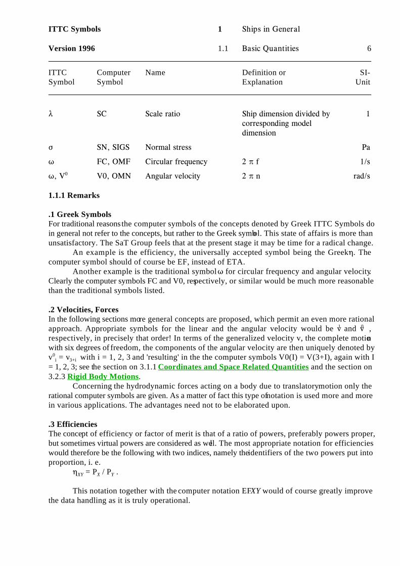
ITTC Symbols 1 Ships in General
Version 1996 1.1 Basic Quantities 6
ITTC Computer Name Definition or SI-Symbol Symbol Explanation Unit
8 SC Scale ratio Ship dimension divided by 1corresponding modeldimension
F SN, SIGS Normal stress Pa
T FC, OMF Circular frequency 2 B f 1/s
T, V V0, OMN Angular velocity 2 B n rad/s0
1.1.1 Remarks
.1 Greek SymbolsFor traditional reasons the computer symbols of the concepts denoted by Greek ITTC Symbols doin general not refer to the concepts, but rather to the Greek symbol. This state of affairs is more thanunsatisfactory. The SaT Group feels that at the present stage it may be time for a radical change.
An example is the efficiency, the universally accepted symbol being the Greek 0. Thecomputer symbol should of course be EF, instead of ETA.
Another example is the traditional symbol T for circular frequency and angular velocity.Clearly the computer symbols FC and V0, respectively, or similar would be much more reasonablethan the traditional symbols listed.
.2 Velocities, ForcesIn the following sections more general concepts are proposed, which permit an even more rationalapproach. Appropriate symbols for the linear and the angular velocity would be v and v ,1 0
respectively, in precisely that order! In terms of the generalized velocity v, the complete motionwith six degrees of freedom, the components of the angular velocity are then uniquely denoted byv = v with i = 1, 2, 3 and 'resulting' in the the computer symbols V0(I) = V(3+I), again with I0
i 3+i
= 1, 2, 3; see the section on 3.1.1 Coordinates and Space Related Quantities and the section on3.2.3 Rigid Body Motions.
Concerning the hydrodynamic forces acting on a body due to translatory motion only therational computer symbols are given. As a matter of fact this type of notation is used more and morein various applications. The advantages need not to be elaborated upon.
.3 EfficienciesThe concept of efficiency or factor of merit is that of a ratio of powers, preferably powers proper,but sometimes virtual powers are considered as well. The most appropriate notation for efficiencieswould therefore be the following with two indices, namely the identifiers of the two powers put intoproportion, i. e.
0 = P / P .XY X Y
This notation together with the computer notation EFXY would of course greatly improvethe data handling as it is truly operational.
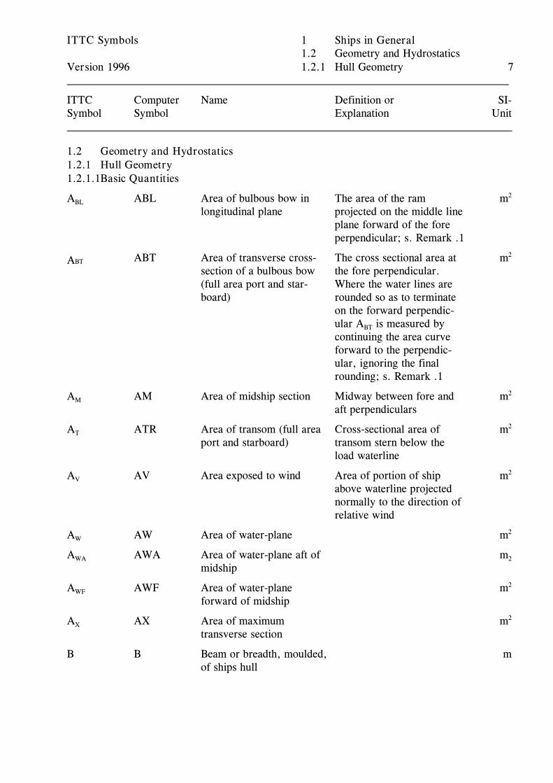
ITTC Symbols 1 Ships in General1.2 Geometry and Hydrostatics
Version 1996 1.2.1 Hull Geometry 7
ITTC Computer Name Definition or SI-Symbol Symbol Explanation Unit
1.2 Geometry and Hydrostatics1.2.1 Hull Geometry1.2.1.1Basic Quantities
A ABL Area of bulbous bow in The area of the ram mBL
longitudinal plane projected on the middle lineplane forward of the foreperpendicular; s. Remark .1
2
ABT Area of transverse cross- The cross sectional area at mBTAsection of a bulbous bow the fore perpendicular. (full area port and star- Where the water lines areboard) rounded so as to terminate
on the forward perpendic-ular A is measured byBT
continuing the area curveforward to the perpendic-ular, ignoring the finalrounding; s. Remark .1
2
A AM Area of midship section Midway between fore and mM
aft perpendiculars
2
A ATR Area of transom (full area Cross-sectional area of mT
port and starboard) transom stern below theload waterline
2
A AV Area exposed to wind Area of portion of ship mV
above waterline projectednormally to the direction ofrelative wind
2
A AW Area of water-plane mW2
A AWA Area of water-plane aft of mWA
midship2
A AWF Area of water-plane mWF
forward of midship
2
A AX Area of maximum mX
transverse section
2
B B Beam or breadth, moulded, mof ships hull
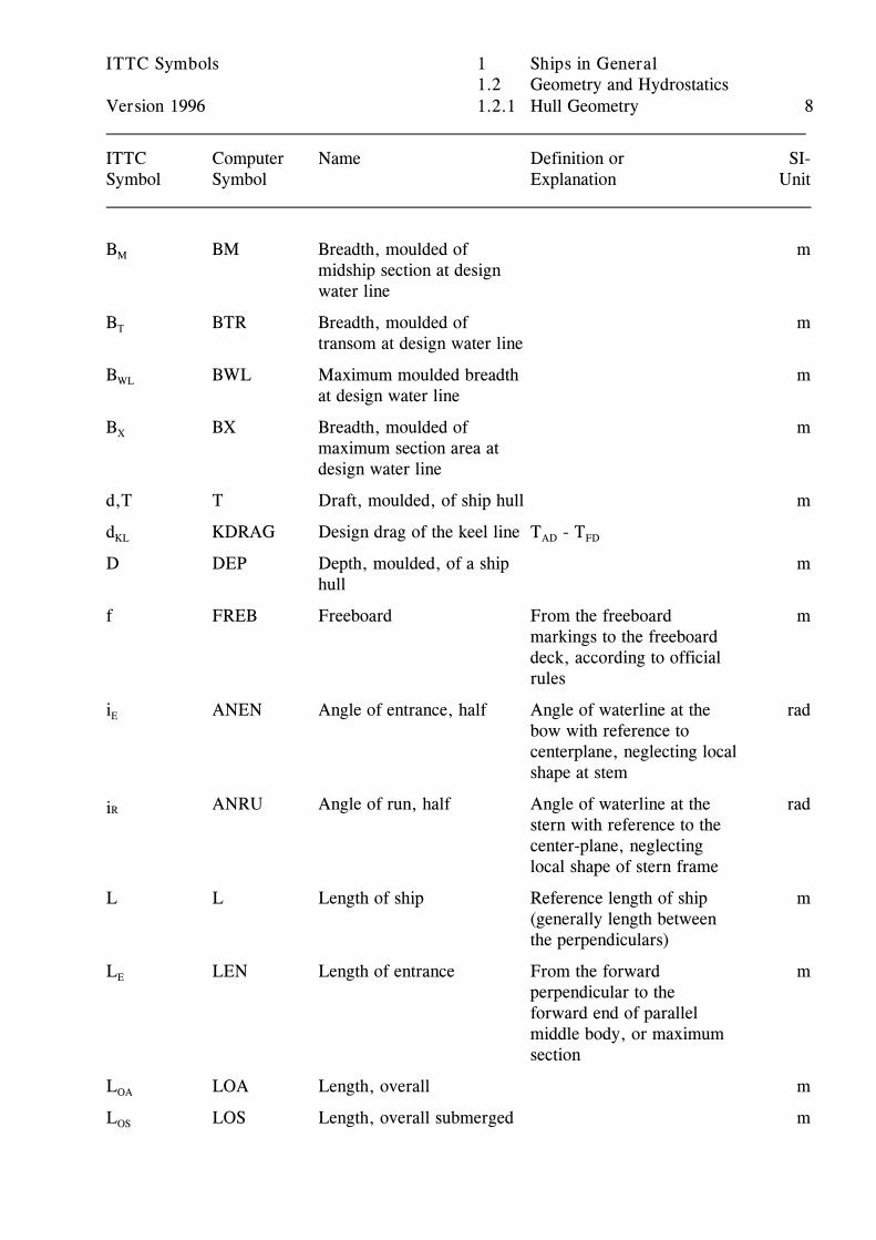
ITTC Symbols 1 Ships in General1.2 Geometry and Hydrostatics
Version 1996 1.2.1 Hull Geometry 8
ITTC Computer Name Definition or SI-Symbol Symbol Explanation Unit
B BM Breadth, moulded of mM
midship section at designwater line
B BTR Breadth, moulded of mT
transom at design water line
B BWL Maximum moulded breadth mWL
at design water line
B BX Breadth, moulded of mX
maximum section area atdesign water line
d,T T Draft, moulded, of ship hull m
d KDRAG Design drag of the keel line T - TKL AD FD
D DEP Depth, moulded, of a ship mhull
f FREB Freeboard From the freeboard mmarkings to the freeboarddeck, according to officialrules
i ANEN Angle of entrance, half Angle of waterline at the radE
bow with reference tocenterplane, neglecting localshape at stem
ANRU Angle of run, half Angle of waterline at the radRistern with reference to thecenter-plane, neglectinglocal shape of stern frame
L L Length of ship Reference length of ship m(generally length betweenthe perpendiculars)
L LEN Length of entrance From the forward mE
perpendicular to theforward end of parallelmiddle body, or maximumsection
L LOA Length, overall mOA
L LOS Length, overall submerged mOS
ITTC Symbols 1 Ships in General1.2 Geometry and Hydrostatics
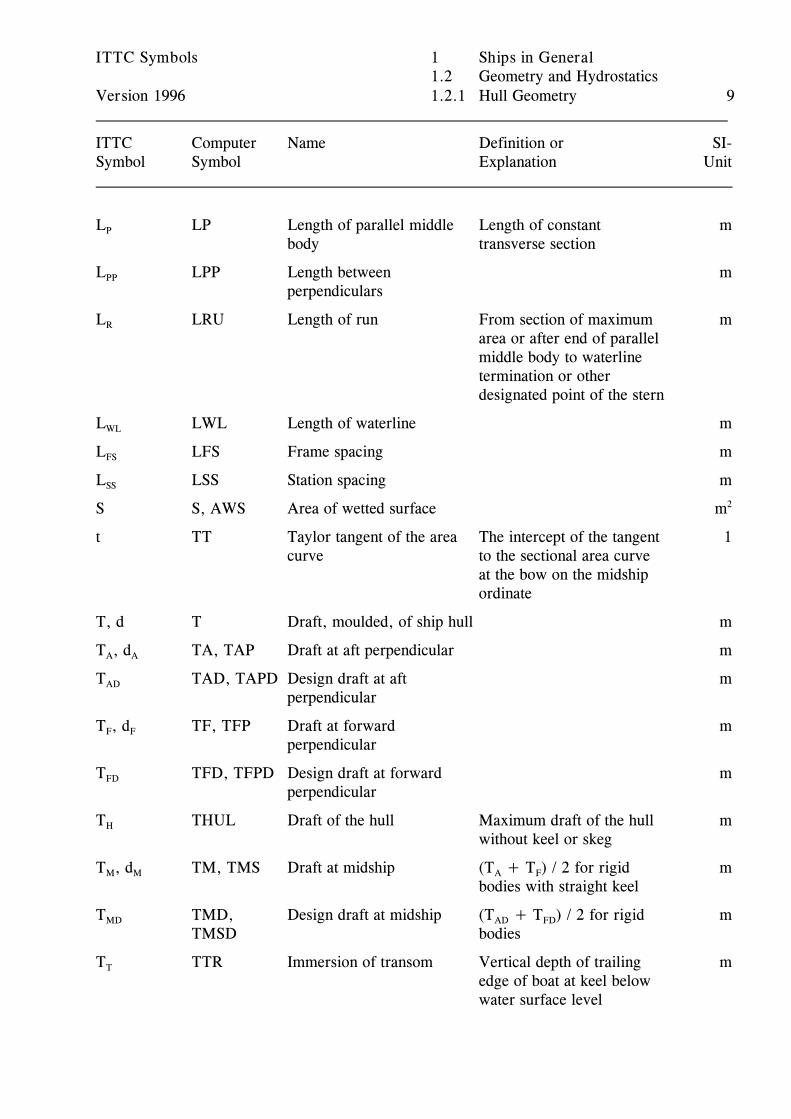
Version 1996 1.2.1 Hull Geometry 9
ITTC Computer Name Definition or SI-Symbol Symbol Explanation Unit
L LP Length of parallel middle Length of constant mP
body transverse section
L LPP Length between mPP
perpendiculars
L LRU Length of run From section of maximum mR
area or after end of parallelmiddle body to waterlinetermination or otherdesignated point of the stern
L LWL Length of waterline mWL
L LFS Frame spacing mFS
L LSS Station spacing mSS
S S, AWS Area of wetted surface m2
t TT Taylor tangent of the area The intercept of the tangent 1curve to the sectional area curve
at the bow on the midshipordinate
T, d T Draft, moulded, of ship hull m
T , d TA, TAP Draft at aft perpendicular mA A
T TAD, TAPD Design draft at aft mAD
perpendicular
T , d TF, TFP Draft at forward mF F
perpendicular
T TFD, TFPD Design draft at forward mFD
perpendicular
T THUL Draft of the hull Maximum draft of the hull mH
without keel or skeg
T , d TM, TMS Draft at midship (T + T ) / 2 for rigid mM M A F
bodies with straight keel
T TMD, Design draft at midship (T + T ) / 2 for rigid mMD
TMSD bodiesAD FD
T TTR Immersion of transom Vertical depth of trailing mT
edge of boat at keel belowwater surface level
ITTC Symbols 1 Ships in General1.2 Geometry and Hydrostatics
Version 1996 1.2.1 Hull Geometry 10
ITTC Computer Name Definition or SI-Symbol Symbol Explanation Unit
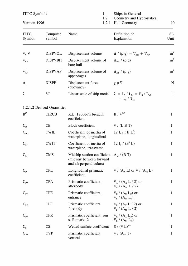
L, V DISPVOL Displacement volume ) / (D g) = L + L mBH AP3
L DISPVBH Displacement volume of ) / (D g) mBH
bare hullBH
3
L DISPVAP Displacement volume of ) / (D g) mAP
appendagesAP
3
) DISPF Displacement force g D L N(buoyancy)
8 SC Linear scale of ship model 8 = L / L = B / B 1S M S M
= T / TS M
1.2.1.2 Derived Quantities
B CIRCB R.E. Froude's breadth B / L 1C
coefficient
1/3
C CB Block coefficient L / (L B T) 1B
C CWIL Coefficient of inertia of 12 I / ( B L ) 1IL
waterplane, longitudinalL
3
C CWIT Coefficient of inertia of 12 I / (B L) 1IT
waterplane, transverseT
3
C CMS Midship section coefficient A / (B T) 1M
(midway between forwardand aft perpendiculars)
M
C CPL Longitudinal prismatic L / (A L) or L / (A L) 1P
coefficientX M
C CPA Prismatic coefficient, L / (A L / 2) or 1PA
afterbody L / (A L / 2)A X
A M
C CPE Prismatic coefficient, L / (A L ) or 1PE
entrance L / (A L )E X E
E M E
C CPF Prismatic coefficient L / (A L / 2) or 1PF
forebody L / (A L / 2)F X
F M
C CPR Prismatic coefficient, run L / (A L ) or 1PR
s. Remark .2 L / (A L )R X R
R M R
C CS Wetted surface coefficient S / (L L) 1S1/2
C CVP Prismatic coefficient L / (A T) 1VP
verticalW

ITTC Symbols 1 Ships in General1.2 Geometry and Hydrostatics
Version 1996 1.2.1 Hull Geometry 11
ITTC Computer Name Definition or SI-Symbol Symbol Explanation Unit
C CWA Water plane area A / (B L / 2) 1WA
coefficient, aftWA
C CWF Water plane area A /(B L / 2) 1WF
coefficient, forwardWF
C CW Water-plane area A /(L B) 1WP
coefficientW
C CX Maximum transverse A / (B T),where B and T 1X
section coefficient are measured at the positionX
of maximum area
C CVOL Volumetric coefficient L / L 1L3
f CABL Area coefficient for bul- A / (L T) 1BL
bous bowBL
f CABT Taylor sectional area A / A 1BT
coefficient for bulbous bowBT X
f CATR Sectional area coefficient A / A 1T
for transom sternT X
M CIRCM R.E. Froude's length L / L 1C
coefficient, or length-displacement ratio
1/3
S CIRCS R.E. Froude's wetted S / L 1C
surface area coefficient
2/3
T CIRCT R.E. Froude's draft T / L 1C
coefficient
1/3
1.1.1.3 Symbols for Attributes and Subscripts
A AB After body
AP After perpendicular
APP Appendages
B BH Bare hull
DW Design waterline
E EN Entry
F FB Fore body
FP Fore perpendicular
ITTC Symbols 1 Ships in General1.2 Geometry and Hydrostatics
Version 1996 1.2.1 Hull Geometry 12
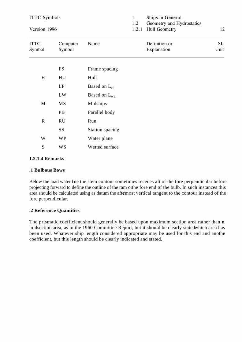
ITTC Computer Name Definition or SI-Symbol Symbol Explanation Unit
FS Frame spacing
H HU Hull
LP Based on LPP
LW Based on LWL
M MS Midships
PB Parallel body
R RU Run
SS Station spacing
W WP Water plane
S WS Wetted surface
1.2.1.4 Remarks
.1 Bulbous Bows
Below the load water line the stem contour sometimes recedes aft of the fore perpendicular beforeprojecting forward to define the outline of the ram or the fore end of the bulb. In such instances thisarea should be calculated using as datum the aftermost vertical tangent to the contour instead of thefore perpendicular.
.2 Reference Quantities
The prismatic coefficient should generally be based upon maximum section area rather than onmidsection area, as in the 1960 Committee Report, but it should be clearly stated which area hasbeen used. Whatever ship length considered appropriate may be used for this end and anothercoefficient, but this length should be clearly indicated and stated.
ITTC Symbols 1 Ships in General1.2 Geometry and Hydrostatics
Version 1996 1.2.2 Propulsor Geometry 13
ITTC Computer Name Definition or SI-Symbol Symbol Explanation Unit
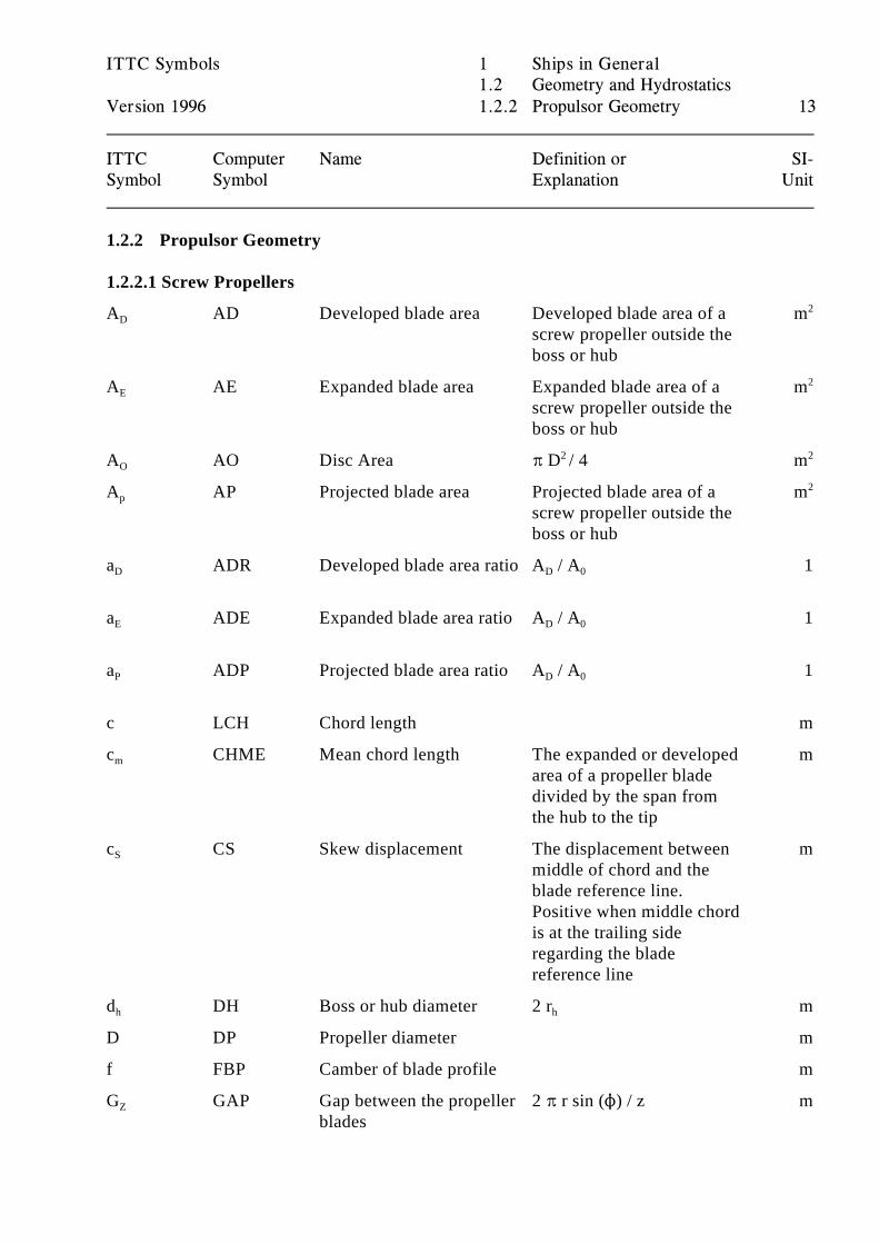
1.2.2 Propulsor Geometry
1.2.2.1 Screw Propellers
A AD Developed blade area Developed blade area of a mD
screw propeller outside theboss or hub
2
A AE Expanded blade area Expanded blade area of a mE
screw propeller outside theboss or hub
2
A AO Disc Area B D / 4 mO2 2
A AP Projected blade area Projected blade area of a mp
screw propeller outside theboss or hub
2
a ADR Developed blade area ratio A / A 1D D 0
a ADE Expanded blade area ratio A / A 1E D 0
a ADP Projected blade area ratio A / A 1P D 0
c LCH Chord length m
c CHME Mean chord length The expanded or developed mm
area of a propeller bladedivided by the span fromthe hub to the tip
c CS Skew displacement The displacement between mS
middle of chord and theblade reference line.Positive when middle chordis at the trailing sideregarding the bladereference line
d DH Boss or hub diameter 2 r mh h
D DP Propeller diameter m
f FBP Camber of blade profile m
G GAP Gap between the propeller 2 B r sin (N) / z mZ
blades
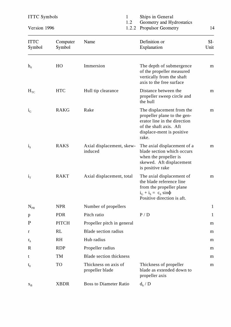
ITTC Symbols 1 Ships in General1.2 Geometry and Hydrostatics
Version 1996 1.2.2 Propulsor Geometry 14
ITTC Computer Name Definition or SI-Symbol Symbol Explanation Unit
h HO Immersion The depth of submergence m0
of the propeller measuredvertically from the shaftaxis to the free surface
H HTC Hull tip clearance Distance between the mTC
propeller sweep circle andthe hull
i RAKG Rake The displacement from the mG
propeller plane to the gen-erator line in the directionof the shaft axis. Aftdisplace-ment is positiverake.
i RAKS Axial displacement, skew- The axial displacement of a mS
induced blade section which occurswhen the propeller isskewed. Aft displacementis positive rake
i RAKT Axial displacement, total The axial displacement of mT
the blade reference linefrom the propeller planei + i = c sinN G S S
Positive direction is aft.
N NPR Number of propellers 1PR
p PDR Pitch ratio P / D 1
C PITCH Propeller pitch in general m
r RL Blade section radius m
r RH Hub radius mh
R RDP Propeller radius m
t TM Blade section thickness m
t TO Thickness on axis of Thickness of propeller m0
propeller blade blade as extended down topropeller axis
x XBDR Boss to Diameter Ratio d / DB h
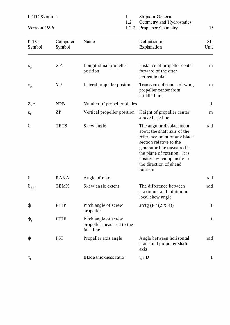
ITTC Symbols 1 Ships in General1.2 Geometry and Hydrostatics
Version 1996 1.2.2 Propulsor Geometry 15
ITTC Computer Name Definition or SI-Symbol Symbol Explanation Unit
x XP Longitudinal propeller Distance of propeller center mp
position forward of the afterperpendicular
y YP Lateral propeller position Transverse distance of wing mp
propeller center frommiddle line
Z, z NPB Number of propeller blades 1
z ZP Vertical propeller position Height of propeller center mp
above base line
2 TETS Skew angle The angular displacement rads
about the shaft axis of thereference point of any bladesection relative to thegenerator line measured inthe plane of rotation. It ispositive when opposite tothe direction of aheadrotation
2 RAKA Angle of rake rad
2 TEMX Skew angle extent The difference between radEXT
maximum and minimumlocal skew angle
N PHIP Pitch angle of screw arctg (P / (2 B R)) 1propeller
N PHIF Pitch angle of screw 1F
propeller measured to theface line
R PSI Propeller axis angle Angle between horizontal radplane and propeller shaftaxis
J Blade thickness ratio t / D 1b 0
ITTC Symbols 1 Ships in General1.2 Geometry and Hydrostatics
Version 1996 1.2.2 Propulsor Geometry 16
ITTC Computer Name Definition or SI-Symbol Symbol Explanation Unit
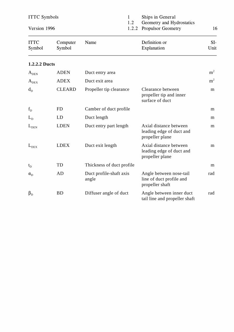
1.2.2.2 Ducts
A ADEN Duct entry area mDEN2
A ADEX Duct exit area mDEX2
d CLEARD Propeller tip clearance Clearance between mD
propeller tip and innersurface of duct
f FD Camber of duct profile mD
L LD Duct length mD
L LDEN Duct entry part length Axial distance between mDEN
leading edge of duct andpropeller plane
L LDEX Duct exit length Axial distance between mDEX
leading edge of duct andpropeller plane
t TD Thickness of duct profile mD
" AD Duct profile-shaft axis Angle between nose-tail radD
angle line of duct profile andpropeller shaft
$ BD Diffuser angle of duct Angle between inner duct radD
tail line and propeller shaft
ITTC Symbols 1 Ships in General1.2 Geometry and Hydrostatics
Version 1996 1.2.3 Appendage Geometry 17
ITTC Computer Name Definition or SI-Symbol Symbol Explanation Unit
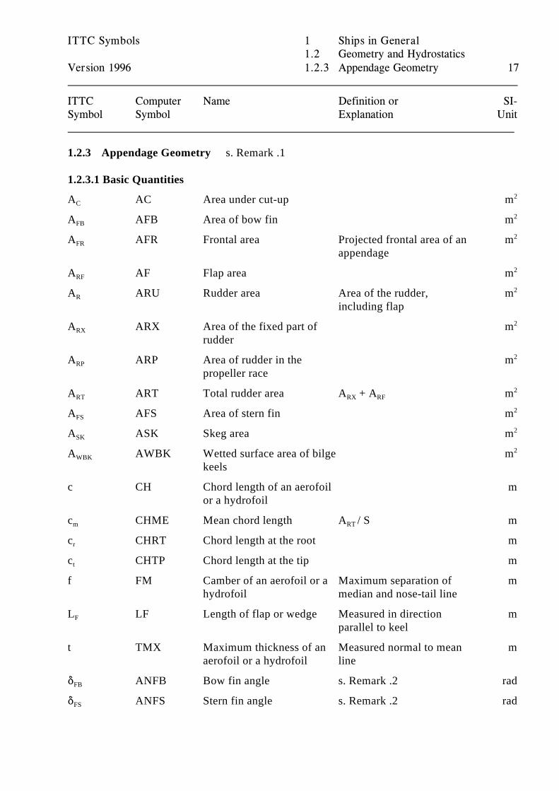
1.2.3 Appendage Geometry s. Remark .1
1.2.3.1 Basic Quantities
A AC Area under cut-up mC2
A AFB Area of bow fin mFB2
A AFR Frontal area Projected frontal area of an mFR
appendage
2
A AF Flap area mRF2
A ARU Rudder area Area of the rudder, mR
including flap
2
A ARX Area of the fixed part of mRX
rudder
2
A ARP Area of rudder in the mRP
propeller race
2
A ART Total rudder area A + A mRT RX RF2
A AFS Area of stern fin mFS2
A ASK Skeg area mSK2
A AWBK Wetted surface area of bilge mWBK
keels
2
c CH Chord length of an aerofoil mor a hydrofoil
c CHME Mean chord length A / S mm RT
c CHRT Chord length at the root mr
c CHTP Chord length at the tip mt
f FM Camber of an aerofoil or a Maximum separation of mhydrofoil median and nose-tail line
L LF Length of flap or wedge Measured in direction mF
parallel to keel
t TMX Maximum thickness of an Measured normal to mean maerofoil or a hydrofoil line
* ANFB Bow fin angle s. Remark .2 radFB
* ANFS Stern fin angle s. Remark .2 radFS
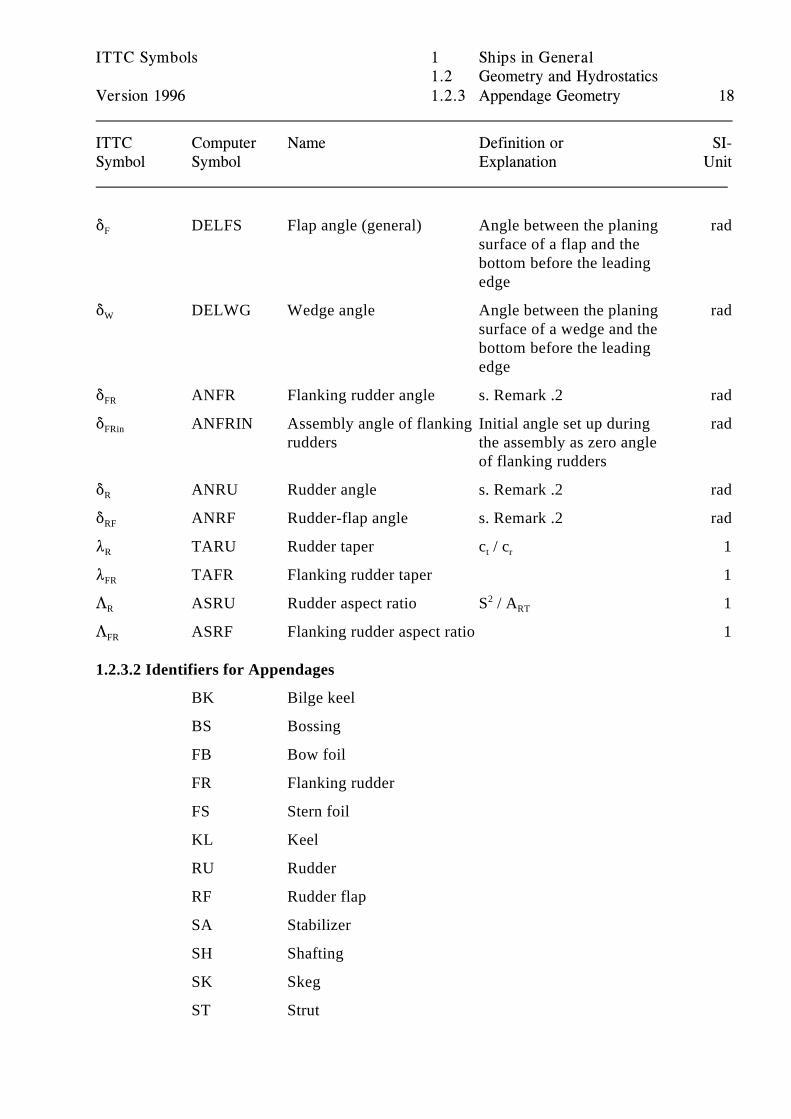
ITTC Symbols 1 Ships in General1.2 Geometry and Hydrostatics
Version 1996 1.2.3 Appendage Geometry 18
ITTC Computer Name Definition or SI-Symbol Symbol Explanation Unit
* DELFS Flap angle (general) Angle between the planing radF
surface of a flap and thebottom before the leadingedge
* DELWG Wedge angle Angle between the planing radW
surface of a wedge and thebottom before the leadingedge
* ANFR Flanking rudder angle s. Remark .2 radFR
* ANFRIN Assembly angle of flanking Initial angle set up during radFRin
rudders the assembly as zero angleof flanking rudders
* ANRU Rudder angle s. Remark .2 radR
* ANRF Rudder-flap angle s. Remark .2 radRF
8 TARU Rudder taper c / c 1R t r
8 TAFR Flanking rudder taper 1FR
7 ASRU Rudder aspect ratio S / A 1R2
RT
7 ASRF Flanking rudder aspect ratio 1FR
1.2.3.2 Identifiers for Appendages
BK Bilge keel
BS Bossing
FB Bow foil
FR Flanking rudder
FS Stern foil
KL Keel
RU Rudder
RF Rudder flap
SA Stabilizer
SH Shafting
SK Skeg
ST Strut
ITTC Symbols 1 Ships in General1.2 Geometry and Hydrostatics
Version 1996 1.2.3 Appendage Geometry 19
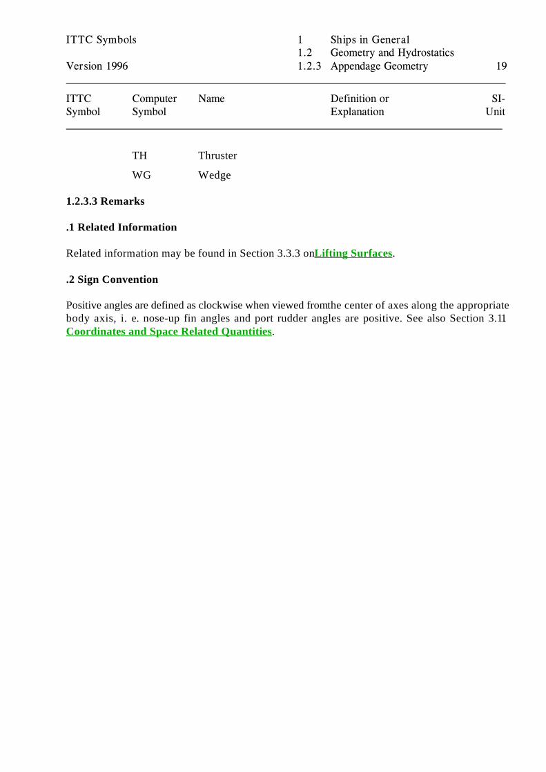
ITTC Computer Name Definition or SI-Symbol Symbol Explanation Unit
TH Thruster
WG Wedge
1.2.3.3 Remarks
.1 Related Information
Related information may be found in Section 3.3.3 on Lifting Surfaces.
.2 Sign Convention
Positive angles are defined as clockwise when viewed from the center of axes along the appropriatebody axis, i. e. nose-up fin angles and port rudder angles are positive. See also Section 3.1.1Coordinates and Space Related Quantities.
ITTC Symbols 1 Ships in General1.2 Geometry and Hydrostatics
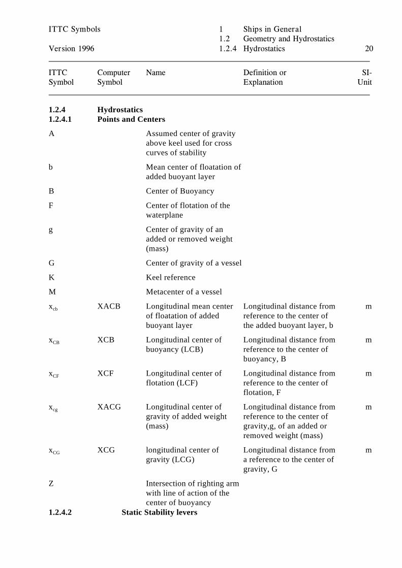
Version 1996 1.2.4 Hydrostatics 20
ITTC Computer Name Definition or SI-Symbol Symbol Explanation Unit
1.2.4 Hydrostatics1.2.4.1 Points and Centers
A Assumed center of gravityabove keel used for crosscurves of stability
b Mean center of floatation ofadded buoyant layer
B Center of Buoyancy
F Center of flotation of thewaterplane
g Center of gravity of anadded or removed weight(mass)
G Center of gravity of a vessel
K Keel reference
M Metacenter of a vessel
x XACB Longitudinal mean center Longitudinal distance from mcb
of floatation of added reference to the center ofbuoyant layer the added buoyant layer, b
x XCB Longitudinal center of Longitudinal distance from mCB
buoyancy (LCB) reference to the center ofbuoyancy, B
x XCF Longitudinal center of Longitudinal distance from mCF
flotation (LCF) reference to the center offlotation, F
x XACG Longitudinal center of Longitudinal distance from mcg
gravity of added weight reference to the center of(mass) gravity,g, of an added or
removed weight (mass)
x XCG longitudinal center of Longitudinal distance from mCG
gravity (LCG) a reference to the center ofgravity, G
Z Intersection of righting armwith line of action of thecenter of buoyancy
1.2.4.2 Static Stability levers
AB
AF
AG
AG
AG
AZ
BM
KM KB
BM KM KB
FB
FF
FG
ITTC Symbols 1 Ships in General1.2 Geometry and Hydrostatics
Version 1996 1.2.4 Hydrostatics 21
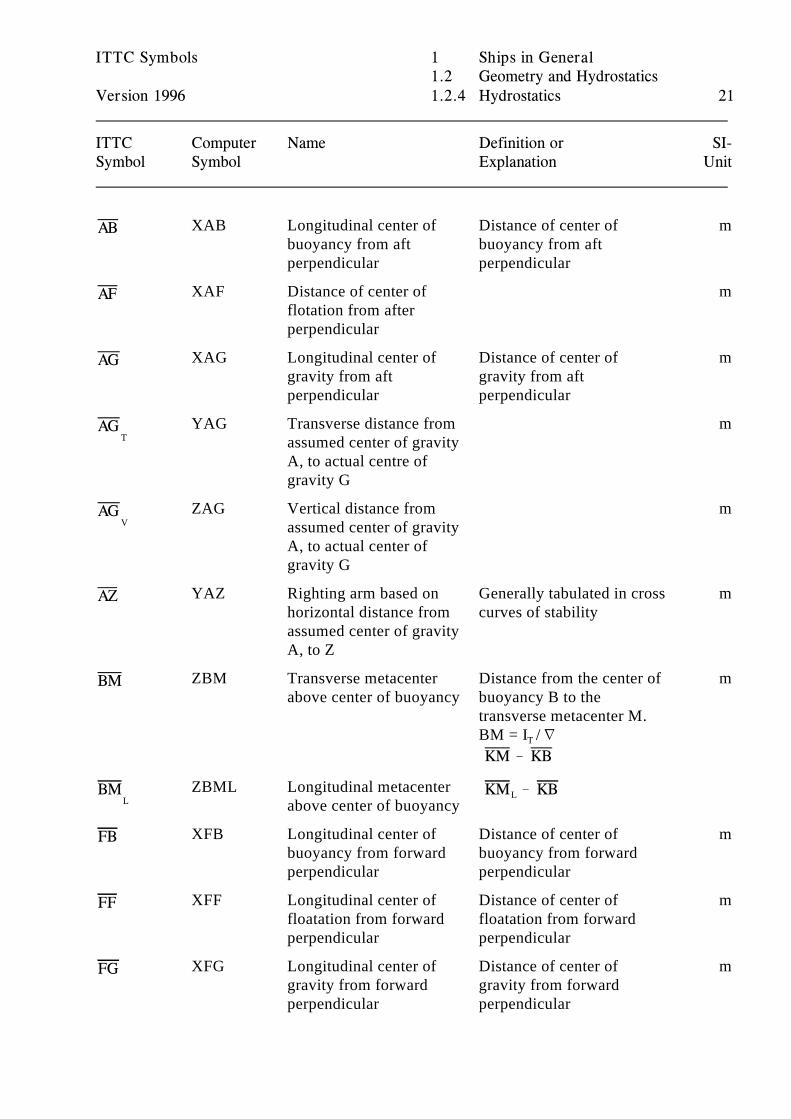
ITTC Computer Name Definition or SI-Symbol Symbol Explanation Unit
XAB Longitudinal center of Distance of center of mbuoyancy from aft buoyancy from aftperpendicular perpendicular
XAF Distance of center of mflotation from afterperpendicular
XAG Longitudinal center of Distance of center of mgravity from aft gravity from aftperpendicular perpendicular
TYAG Transverse distance from m
assumed center of gravityA, to actual centre ofgravity G
VZAG Vertical distance from m
assumed center of gravityA, to actual center ofgravity G
YAZ Righting arm based on Generally tabulated in cross mhorizontal distance from curves of stabilityassumed center of gravityA, to Z
ZBM Transverse metacenter Distance from the center of mabove center of buoyancy buoyancy B to the
transverse metacenter M. BM = I / LT
!
LZBML Longitudinal metacenter
above center of buoyancy ! L
XFB Longitudinal center of Distance of center of mbuoyancy from forward buoyancy from forwardperpendicular perpendicular
XFF Longitudinal center of Distance of center of mfloatation from forward floatation from forwardperpendicular perpendicular
XFG Longitudinal center of Distance of center of mgravity from forward gravity from forwardperpendicular perpendicular
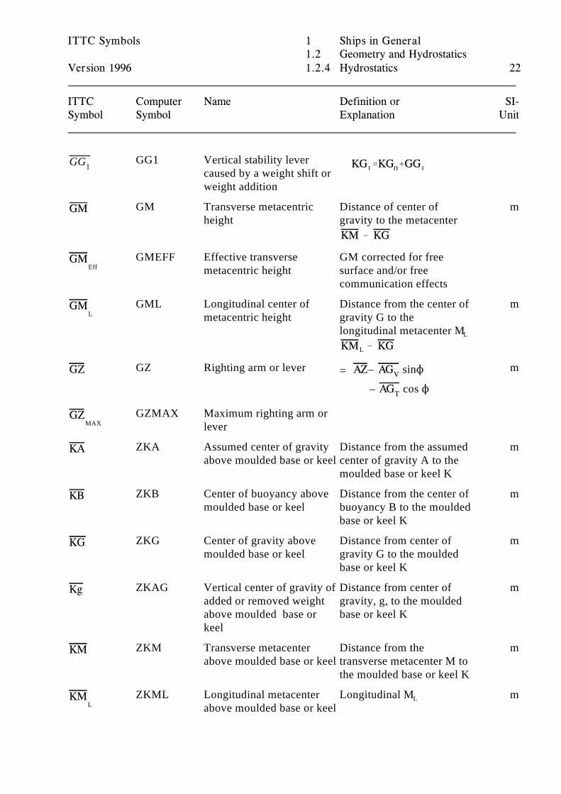
KG1'KG0%GG1GG1
GM
KM KG
GM
GM
KM KG
GZ AZ AGV
AGT
GZ
KA
KB
KG
Kg
KM
KM
ITTC Symbols 1 Ships in General1.2 Geometry and Hydrostatics
Version 1996 1.2.4 Hydrostatics 22
ITTC Computer Name Definition or SI-Symbol Symbol Explanation Unit
GG1 Vertical stability levercaused by a weight shift orweight addition
GM Transverse metacentric Distance of center of mheight gravity to the metacenter
!
EffGMEFF Effective transverse GM corrected for free
metacentric height surface and/or freecommunication effects
LGML Longitudinal center of Distance from the center of m
metacentric height gravity G to thelongitudinal metacenter ML
! L
GZ Righting arm or lever m – sinN=
– cos N
MAXGZMAX Maximum righting arm or
lever
ZKA Assumed center of gravity Distance from the assumed mabove moulded base or keel center of gravity A to the
moulded base or keel K
ZKB Center of buoyancy above Distance from the center of mmoulded base or keel buoyancy B to the moulded
base or keel K
ZKG Center of gravity above Distance from center of mmoulded base or keel gravity G to the moulded
base or keel K
ZKAG Vertical center of gravity of Distance from center of madded or removed weight gravity, g, to the mouldedabove moulded base or base or keel Kkeel
ZKM Transverse metacenter Distance from the mabove moulded base or keel transverse metacenter M to
the moulded base or keel K
LZKML Longitudinal metacenter Longitudinal M m
above moulded base or keelL
ITTC Symbols 1 Ships in General1.2 Geometry and Hydrostatics
Version 1996 1.2.4 Hydrostatics 23
ITTC Computer Name Definition or SI-Symbol Symbol Explanation Unit
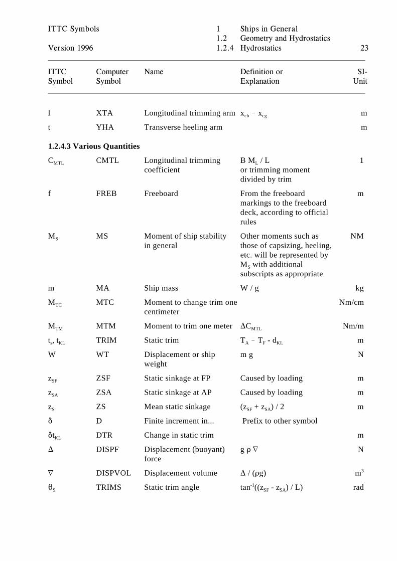
l XTA Longitudinal trimming arm x ! x mcb cg
t YHA Transverse heeling arm m
1.2.4.3 Various Quantities
C CMTL Longitudinal trimming B M / L 1MTL
coefficient or trimming moment L
divided by trim
f FREB Freeboard From the freeboard mmarkings to the freeboarddeck, according to officialrules
M MS Moment of ship stability Other moments such as NMS
in general those of capsizing, heeling,etc. will be represented byM with additionalS
subscripts as appropriate
m MA Ship mass W / g kg
M MTC Moment to change trim one Nm/cmTC
centimeter
M MTM Moment to trim one meter )C Nm/mTM MTL
t , t TRIM Static trim T ! T - d ms KL A F KL
W WT Displacement or ship m g Nweight
z ZSF Static sinkage at FP Caused by loading mSF
z ZSA Static sinkage at AP Caused by loading mSA
z ZS Mean static sinkage (z + z ) / 2 mS SF SA
* D Finite increment in... Prefix to other symbol
*t DTR Change in static trim mKL
) DISPF Displacement (buoyant) g D L Nforce
L DISPVOL Displacement volume ) / (Dg) m3
2 TRIMS Static trim angle tan ((z - z ) / L) radS-1
SF SA
ITTC Symbols 1 Ships in General1.2 Geometry and Hydrostatics
Version 1996 1.2.4 Hydrostatics 24
ITTC Computer Name Definition or SI-Symbol Symbol Explanation Unit
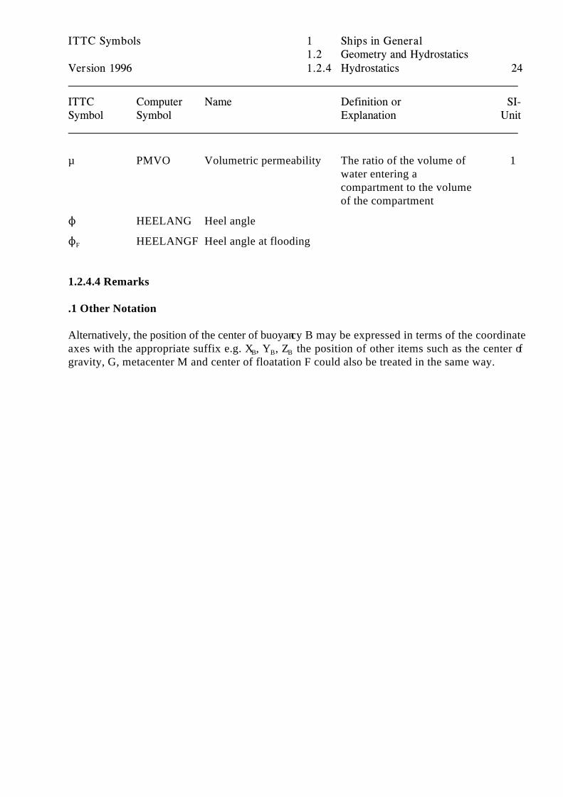
µ PMVO Volumetric permeability The ratio of the volume of 1water entering acompartment to the volumeof the compartment
N HEELANG Heel angle
N HEELANGF Heel angle at flooding F
1.2.4.4 Remarks
.1 Other Notation
Alternatively, the position of the center of buoyancy B may be expressed in terms of the coordinateaxes with the appropriate suffix e.g. X , Y , Z the position of other items such as the center ofB B B
gravity, G, metacenter M and center of floatation F could also be treated in the same way.
ITTC Symbols 1 Ships in General1.3 Resistance and Propulsion
Version 1996 1.3.1 Hull Resistance 25
ITTC Computer Name Definition or SI-Symbol Symbol Explanation Unit
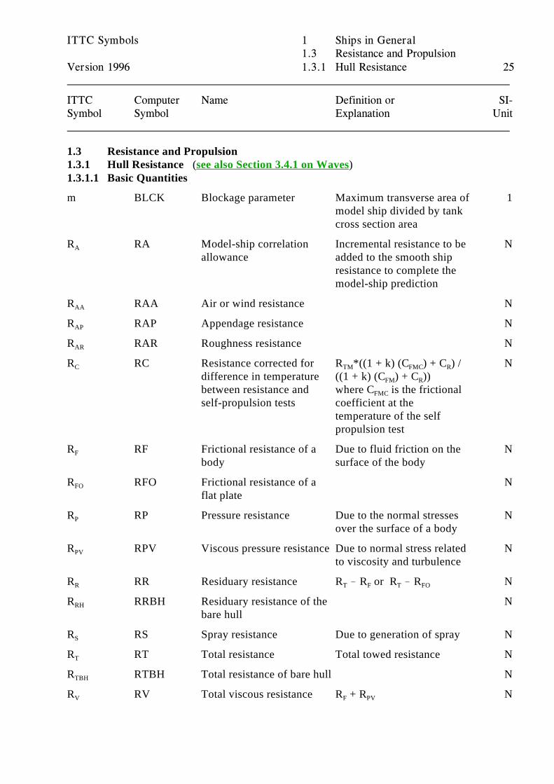
1.3 Resistance and Propulsion1.3.1 Hull Resistance (see also Section 3.4.1 on Waves)1.3.1.1 Basic Quantities
m BLCK Blockage parameter Maximum transverse area of 1model ship divided by tankcross section area
R RA Model-ship correlation Incremental resistance to be NA
allowance added to the smooth shipresistance to complete themodel-ship prediction
R RAA Air or wind resistance NAA
R RAP Appendage resistance NAP
R RAR Roughness resistance NAR
R RC Resistance corrected for R *((1 + k) (C ) + C ) / NC
difference in temperature ((1 + k) (C ) + C ))between resistance and where C is the frictionalself-propulsion tests coefficient at the
TM FMC R
FM R
FMC
temperature of the selfpropulsion test
R RF Frictional resistance of a Due to fluid friction on the NF
body surface of the body
R RFO Frictional resistance of a NFO
flat plate
R RP Pressure resistance Due to the normal stresses NP
over the surface of a body
R RPV Viscous pressure resistance Due to normal stress related NPV
to viscosity and turbulence
R RR Residuary resistance R ! R or R ! R NR T F T FO
R RRBH Residuary resistance of the NRH
bare hull
R RS Spray resistance Due to generation of spray NS
R RT Total resistance Total towed resistance NT
R RTBH Total resistance of bare hull NTBH
R RV Total viscous resistance R + R NV F PV
ITTC Symbols 1 Ships in General1.3 Resistance and Propulsion
Version 1996 1.3.1 Hull Resistance 26
ITTC Computer Name Definition or SI-Symbol Symbol Explanation Unit
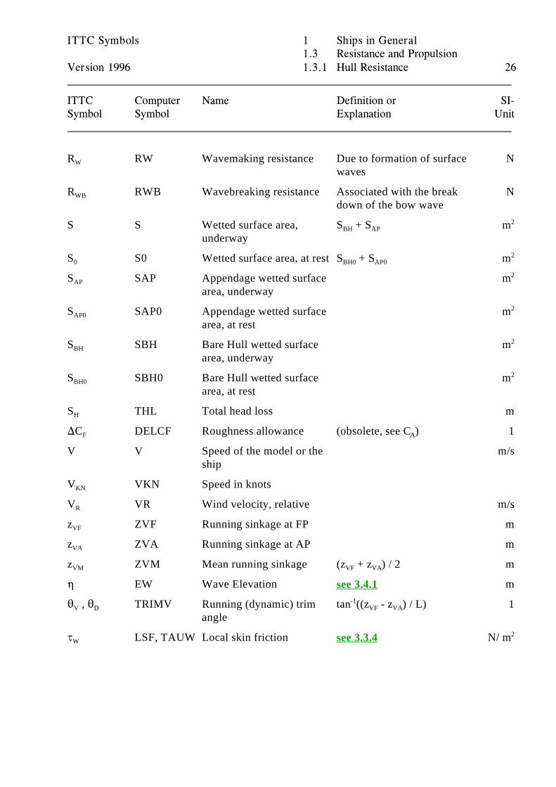
R RW Wavemaking resistance Due to formation of surface NW
waves
R RWB Wavebreaking resistance Associated with the break NWB
down of the bow wave
S S Wetted surface area, S + S munderway
BH AP2
S S0 Wetted surface area, at rest S + S m0 BH0 AP02
S SAP Appendage wetted surface mAP
area, underway
2
S SAP0 Appendage wetted surface mAP0
area, at rest
2
S SBH Bare Hull wetted surface mBH
area, underway
2
S SBH0 Bare Hull wetted surface mBH0
area, at rest
2
S THL Total head loss mH
)C DELCF Roughness allowance (obsolete, see C ) 1F A
V V Speed of the model or the m/sship
V VKN Speed in knotsKN
V VR Wind velocity, relative m/sR
z ZVF Running sinkage at FP mVF
z ZVA Running sinkage at AP mVA
z ZVM Mean running sinkage (z + z ) / 2 mVM VF VA
0 EW Wave Elevation msee 3.4.1
2 , 2 TRIMV Running (dynamic) trim tan ((z - z ) / L) 1V D
angle
-1VF VA
J LSF, TAUW Local skin friction N/ mW see 3.3.4 2
ITTC Symbols 1 Ships in General1.3 Resistance and Propulsion
Version 1996 1.3.1 Hull Resistance 27
ITTC Computer Name Definition or SI-Symbol Symbol Explanation Unit
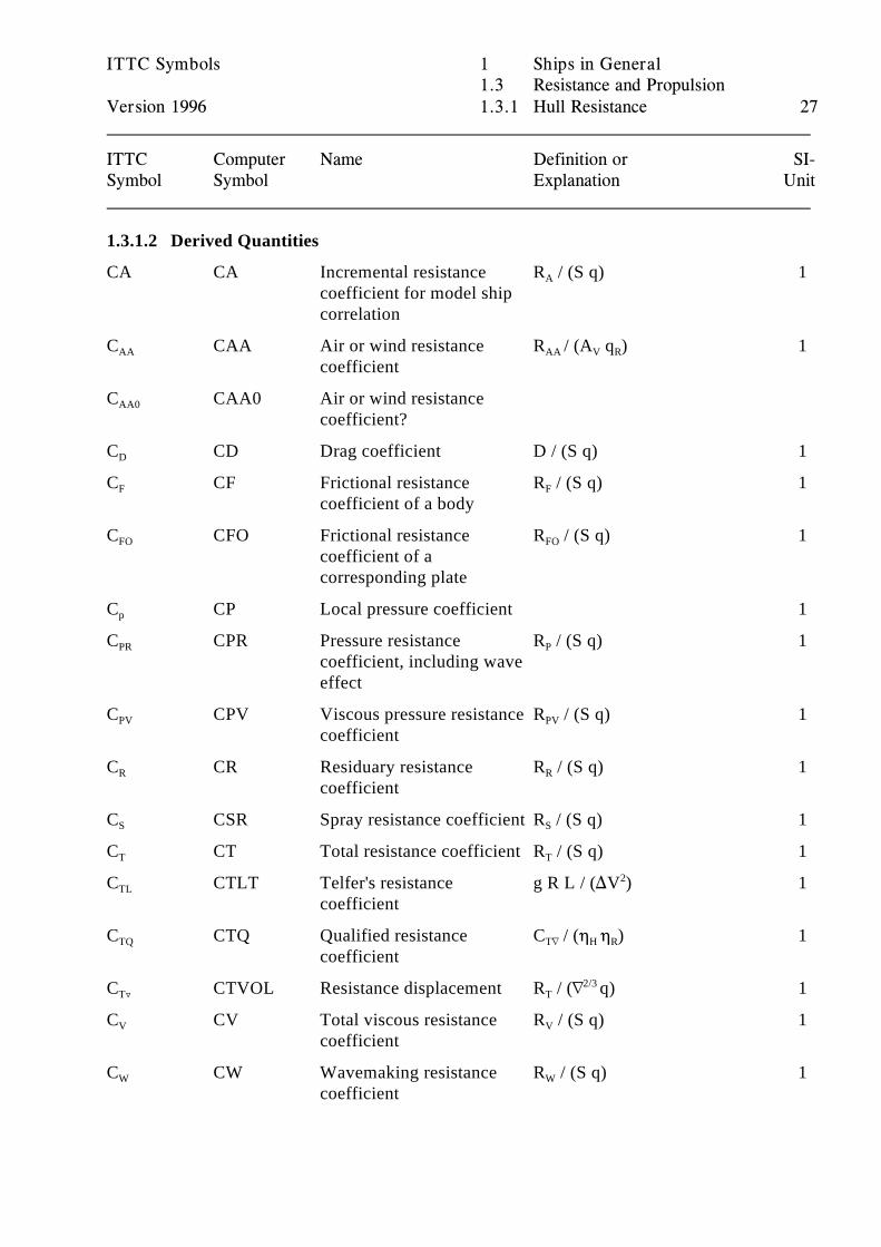
1.3.1.2 Derived Quantities
CA CA Incremental resistance R / (S q) 1coefficient for model shipcorrelation
A
C CAA Air or wind resistance R / (A q ) 1AA
coefficientAA V R
C CAA0 Air or wind resistanceAA0
coefficient?
C CD Drag coefficient D / (S q) 1D
C CF Frictional resistance R / (S q) 1F
coefficient of a bodyF
C CFO Frictional resistance R / (S q) 1FO
coefficient of acorresponding plate
FO
C CP Local pressure coefficient 1p
C CPR Pressure resistance R / (S q) 1PR
coefficient, including waveeffect
P
C CPV Viscous pressure resistance R / (S q) 1PV
coefficientPV
C CR Residuary resistance R / (S q) 1R
coefficientR
C CSR Spray resistance coefficient R / (S q) 1S S
C CT Total resistance coefficient R / (S q) 1T T
C CTLT Telfer's resistance g R L / ()V ) 1TL
coefficient
2
C CTQ Qualified resistance C / (0 0 ) 1TQ
coefficientTL H R
C CTVOL Resistance displacement R / (L q) 1T« T2/3
C CV Total viscous resistance R / (S q) 1V
coefficientV
C CW Wavemaking resistance R / (S q) 1W
coefficientW
ITTC Symbols 1 Ships in General1.3 Resistance and Propulsion
Version 1996 1.3.1 Hull Resistance 28
ITTC Computer Name Definition or SI-Symbol Symbol Explanation Unit
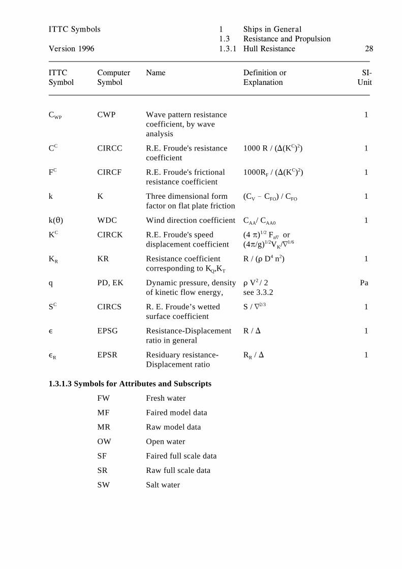
C CWP Wave pattern resistance 1WP
coefficient, by waveanalysis
C CIRCC R.E. Froude's resistance 1000 R / ()(K ) ) 1C
coefficient
C 2
F CIRCF R.E. Froude's frictional 1000R / ()(K ) ) 1C
resistance coefficientF
C 2
k K Three dimensional form (C ! C ) / C 1factor on flat plate friction
V FO FO
k(2) WDC Wind direction coefficient C / C 1AA AA0
K CIRCK R.E. Froude's speed (4 B) F orC
displacement coefficient (4B/g) V /L
1/2nL
1/2 1/6K
K KR Resistance coefficient R / (D D n ) 1R
corresponding to K ,KQ T
4 2
q PD, EK Dynamic pressure, density D V / 2 Paof kinetic flow energy, see 3.3.2
2
S CIRCS R. E. Froude’s wetted S / L 1C
surface coefficient
2/3
, EPSG Resistance-Displacement R / ) 1ratio in general
, EPSR Residuary resistance- R / ) 1R
Displacement ratioR
1.3.1.3 Symbols for Attributes and Subscripts
FW Fresh water
MF Faired model data
MR Raw model data
OW Open water
SF Faired full scale data
SR Raw full scale data
SW Salt water
ITTC Symbols 1 Ships in General1.3 Resistance and Propulsion
Version 1996 1.3.2 Ship Performance 29
ITTC Computer Name Definition or SI-Symbol Symbol Explanation Unit
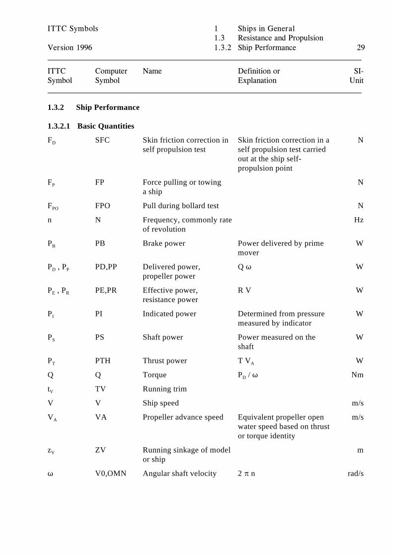
1.3.2 Ship Performance
1.3.2.1 Basic Quantities
F SFC Skin friction correction in Skin friction correction in a ND
self propulsion test self propulsion test carriedout at the ship self-propulsion point
F FP Force pulling or towing NP
a ship
F FPO Pull during bollard test NPO
n N Frequency, commonly rate Hzof revolution
P PB Brake power Power delivered by prime WB
mover
P , P PD,PP Delivered power, Q T WD P
propeller power
P , P PE,PR Effective power, R V WE R
resistance power
P PI Indicated power Determined from pressure WI
measured by indicator
P PS Shaft power Power measured on the WS
shaft
P PTH Thrust power T V WT A
Q Q Torque P / T NmD
t TV Running trimV
V V Ship speed m/s
V VA Propeller advance speed Equivalent propeller open m/sA
water speed based on thrustor torque identity
z ZV Running sinkage of model mV
or ship
T V0,OMN Angular shaft velocity 2 B n rad/s
ITTC Symbols 1 Ships in General1.3 Resistance and Propulsion
Version 1996 1.3.2 Ship Performance 30
ITTC Computer Name Definition or SI-Symbol Symbol Explanation Unit
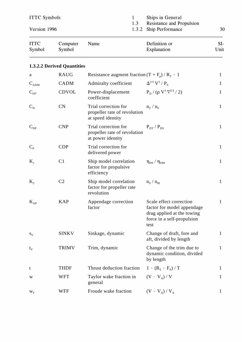
1.3.2.2 Derived Quantities
a RAUG Resistance augment fraction (T + F ) / R ! 1 1p T
C CADM Admiralty coefficient ) V / P 1ADM2/3 3
S
C CDVOL Power-displacement P / (D V L / 2) 1DL
coefficientD
3 2/3
C CN Trial correction for n / n 1N
propeller rate of revolutionat speed identity
T S
C CNP Trial correction for P / P 1NP
propeller rate of revolutionat power identity
DT DS
C CDP Trial correction for 1P
delivered power
K C1 Ship model correlation 0 / 0 11
factor for propulsiveefficiency
DS DM
K C2 Ship model correlation n / n 12
factor for propeller raterevolution
S M
K KAP Appendage correction Scale effect correction 1AP
factor factor for model appendagedrag applied at the towingforce in a self-propulsiontest
s SINKV Sinkage, dynamic Change of draft, fore and 1V
aft, divided by length
t TRIMV Trim, dynamic Change of the trim due to 1V
dynamic condition, dividedby length
t THDF Thrust deduction fraction 1 ! (R ! F ) / T 1T P
w WFT Taylor wake fraction in (V ! V ) / V 1general
A
w WFF Froude wake fraction (V ! V ) / V 1F A A
ITTC Symbols 1 Ships in General1.3 Resistance and Propulsion
Version 1996 1.3.2 Ship Performance 31
ITTC Computer Name Definition or SI-Symbol Symbol Explanation Unit
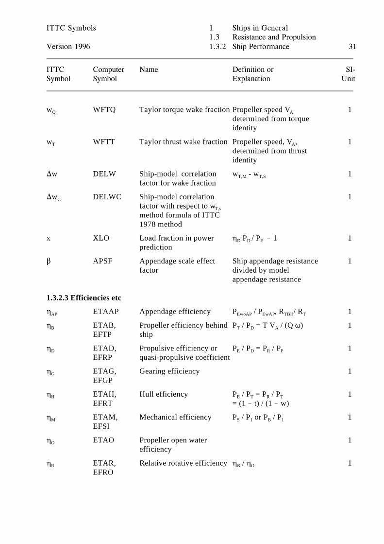
w WFTQ Taylor torque wake fraction Propeller speed V 1Q A
determined from torqueidentity
w WFTT Taylor thrust wake fraction Propeller speed, V , 1T A
determined from thrustidentity
)w DELW Ship-model correlation w - w 1factor for wake fraction
T,M T,S
)w DELWC Ship-model correlation 1C
factor with respect to wT,s
method formula of ITTC1978 method
x XLO Load fraction in power 0 P / P ! 1 1prediction
D D E
$ APSF Appendage scale effect Ship appendage resistance 1factor divided by model
appendage resistance
1.3.2.3 Efficiencies etc
0 ETAAP Appendage efficiency P / P , R / R 1AP EwoAP EwAP TBH T
0 ETAB, Propeller efficiency behind P / P = T V / (Q T) 1B
EFTP shipT D A
0 ETAD, Propulsive efficiency or P / P = P / P 1D
EFRP quasi-propulsive coefficientE D R P
0 ETAG, Gearing efficiency 1G
EFGP
0 ETAH, Hull efficiency P / P = P / P 1H
EFRT = (1 ! t) / (1 ! w)E T R T
0 ETAM, Mechanical efficiency P / P or P / P 1M
EFSIS 1 B 1
0 ETAO Propeller open water 1O
efficiency
0 ETAR, Relative rotative efficiency 0 / 0 1R
EFROB O
ITTC Symbols 1 Ships in General1.3 Resistance and Propulsion
Version 1996 1.3.2 Ship Performance 32
ITTC Computer Name Definition or SI-Symbol Symbol Explanation Unit
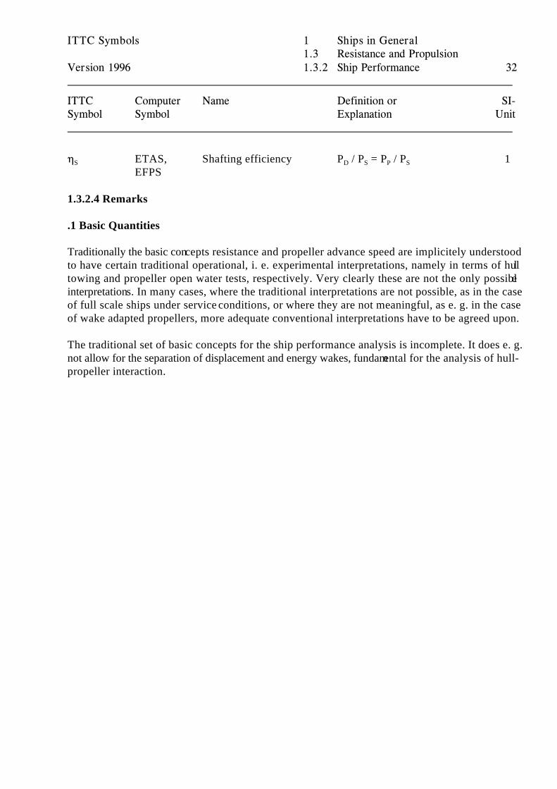
0 ETAS, Shafting efficiency P / P = P / P 1S
EFPSD S P S
1.3.2.4 Remarks
.1 Basic Quantities
Traditionally the basic concepts resistance and propeller advance speed are implicitely understoodto have certain traditional operational, i. e. experimental interpretations, namely in terms of hulltowing and propeller open water tests, respectively. Very clearly these are not the only possibleinterpretations. In many cases, where the traditional interpretations are not possible, as in the caseof full scale ships under service conditions, or where they are not meaningful, as e. g. in the caseof wake adapted propellers, more adequate conventional interpretations have to be agreed upon.
The traditional set of basic concepts for the ship performance analysis is incomplete. It does e. g.not allow for the separation of displacement and energy wakes, fundamental for the analysis of hull-propeller interaction.
ITTC Symbols 1 Ships in General1.3 Resistance and Propulsion
Version 1996 1.3.3 Propulsor Performance 33
ITTC Computer Name Definition or SI-Symbol Symbol Explanation Unit
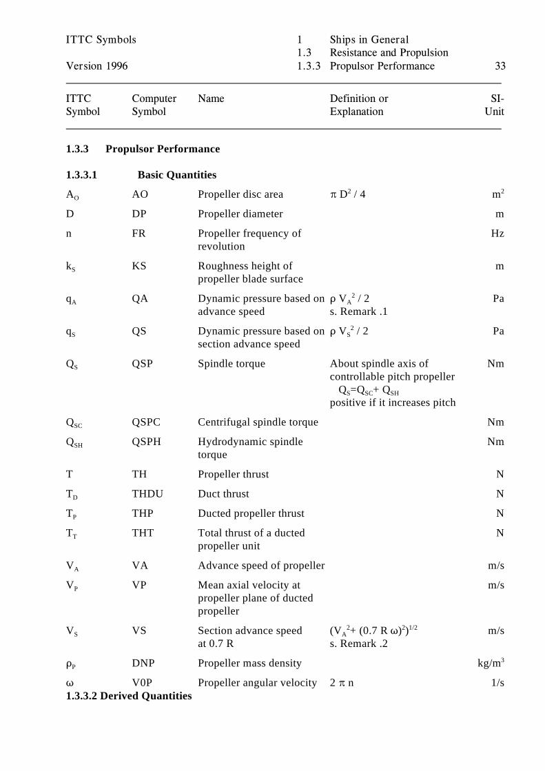
1.3.3 Propulsor Performance
1.3.3.1 Basic Quantities
A AO Propeller disc area B D / 4 mO2 2
D DP Propeller diameter m
n FR Propeller frequency of Hzrevolution
k KS Roughness height of mS
propeller blade surface
q QA Dynamic pressure based on D V / 2 PaA
advance speed s. Remark .1A
2
q QS Dynamic pressure based on D V / 2 PaS
section advance speedS
2
Q QSP Spindle torque About spindle axis of NmS
controllable pitch propeller Q =Q + Q S SC SH
positive if it increases pitch
Q QSPC Centrifugal spindle torque NmSC
Q QSPH Hydrodynamic spindle NmSH
torque
T TH Propeller thrust N
T THDU Duct thrust ND
T THP Ducted propeller thrust NP
T THT Total thrust of a ducted NT
propeller unit
V VA Advance speed of propeller m/sA
V VP Mean axial velocity at m/sP
propeller plane of ductedpropeller
V VS Section advance speed (V + (0.7 R T) ) m/sS
at 0.7 R s. Remark .2A
2 2 1/2
D DNP Propeller mass density kg/mP3
T V0P Propeller angular velocity 2 B n 1/s1.3.3.2 Derived Quantities
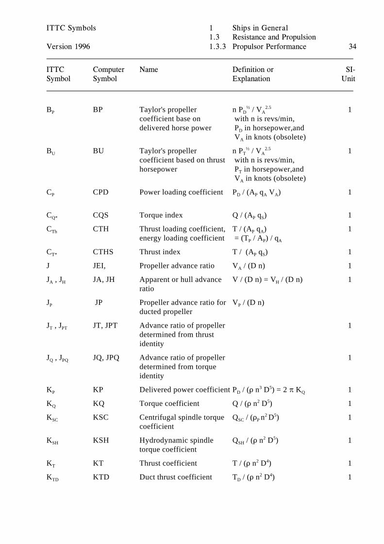
ITTC Symbols 1 Ships in General1.3 Resistance and Propulsion
Version 1996 1.3.3 Propulsor Performance 34
ITTC Computer Name Definition or SI-Symbol Symbol Explanation Unit
B BP Taylor's propeller n P / V 1P
coefficient base on with n is revs/min,delivered horse power P in horsepower,and
D A½ 2.5
D
V in knots (obsolete)A
B BU Taylor's propeller n P / V 1U
coefficient based on thrust with n is revs/min, horsepower P in horsepower,and
T A½ 2.5
T
V in knots (obsolete)A
C CPD Power loading coefficient P / (A q V ) 1P D P A A
C CQS Torque index Q / (A q ) 1Q* P S
C CTH Thrust loading coefficient, T / (A q ) 1Th
energy loading coefficient = (T / A ) / q P A
P P A
C CTHS Thrust index T / (A q ) 1T* P S
J JEI, Propeller advance ratio V / (D n) 1A
J , J JA, JH Apparent or hull advance V / (D n) = V / (D n) 1A H
ratioH
J JP Propeller advance ratio for V / (D n)P
ducted propellerP
J , J JT, JPT Advance ratio of propeller 1T PT
determined from thrustidentity
J , J JQ, JPQ Advance ratio of propeller 1Q PQ
determined from torqueidentity
K KP Delivered power coefficient P / (D n D ) = 2 B K 1P D Q3 5
K KQ Torque coefficient Q / (D n D ) 1Q2 5
K KSC Centrifugal spindle torque Q / (D n D ) 1SC
coefficientSC P
2 5
K KSH Hydrodynamic spindle Q / (D n D ) 1SH
torque coefficientSH
2 5
K KT Thrust coefficient T / (D n D ) 1T2 4
K KTD Duct thrust coefficient T / (D n D ) 1TD D2 4
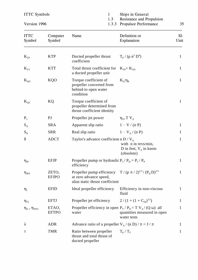
ITTC Symbols 1 Ships in General1.3 Resistance and Propulsion
Version 1996 1.3.3 Propulsor Performance 35
ITTC Computer Name Definition or SI-Symbol Symbol Explanation Unit
K KTP Ducted propeller thrust T / (D n D ) 1TP
coefficientP
2 4
K KTT Total thrust coefficient for K + K 1TT
a ducted propeller unitTP TD
K KQO Torque coefficient of K 0 1QO
propeller converted frombehind to open watercondition
Q R.
K KQ Torque coefficient of 1QT
propeller determined fromthrust coefficient identity
P PJ Propeller jet power 0 T VJ TJ A
S SRA Apparent slip ratio 1 ! V / (n P) 1A
S SRR Real slip ratio 1 ! V / (n P) 1R A
* ADCT Taylor's advance coefficient n D / V 1A
with n in revs/min, D in feet, V in knotsA
(obsolete)
0 EFJP Propeller pump or hydraulic P / P = P / P 1JP
efficiencyJ D J P
0 ZETO, Propeller pump efficiency T / (D B / 2) / (P D) 1JP0
EFJPO at zero advance speed,alias static thrust coefficient
1/3 2/3D
0 EFID Ideal propeller efficiency Efficiency in non-viscous 1I
fluid
0 EFTJ Propeller jet efficiency 2 / (1 + (1 + C ) ) 1TJ Th1/2
0 , 0 ETAO, Propeller efficiency in open P / P = T V / (Q T) all 1O TPO
EFTPO water quantities measured in openT D A
water tests
8 ADR Advance ratio of a propeller V / (n D) / B = J / B 1A
J TMR Ratio between propeller T / T 1thrust and total thrust ofducted propeller
P T
ITTC Symbols 1 Ships in General1.3 Resistance and Propulsion
Version 1996 1.3.3 Propulsor Performance 36
ITTC Computer Name Definition or SI-Symbol Symbol Explanation Unit
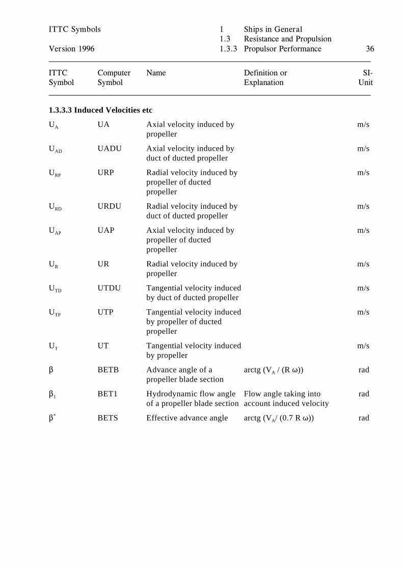
1.3.3.3 Induced Velocities etc
U UA Axial velocity induced by m/sA
propeller
U UADU Axial velocity induced by m/sAD
duct of ducted propeller
U URP Radial velocity induced by m/sRP
propeller of ductedpropeller
U URDU Radial velocity induced by m/sRD
duct of ducted propeller
U UAP Axial velocity induced by m/sAP
propeller of ductedpropeller
U UR Radial velocity induced by m/sR
propeller
U UTDU Tangential velocity induced m/sTD
by duct of ducted propeller
U UTP Tangential velocity induced m/sTP
by propeller of ductedpropeller
U UT Tangential velocity induced m/sT
by propeller
$ BETB Advance angle of a arctg (V / (R T)) radpropeller blade section
A
$ BET1 Hydrodynamic flow angle Flow angle taking into rad1
of a propeller blade section account induced velocity
$ BETS Effective advance angle arctg (V / (0.7 R T)) rad*A
ITTC Symbols 1 Ships in General1.3 Resistance and Propulsion
Version 1996 1.3.3 Propulsor Performance 37
ITTC Computer Name Definition or SI-Symbol Symbol Explanation Unit
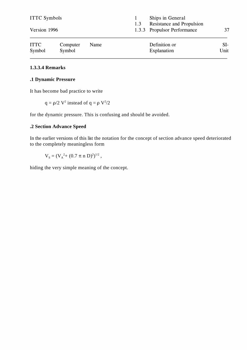
1.3.3.4 Remarks
.1 Dynamic Pressure
It has become bad practice to write
q = D/2 V instead of q = D V /22 2
for the dynamic pressure. This is confusing and should be avoided.
.2 Section Advance Speed
In the earlier versions of this list the notation for the concept of section advance speed deterioratedto the completely meaningless form
V = (V + (0.7 B n D) ) ,S A2 2 1/2
hiding the very simple meaning of the concept.
ITTC Symbols 1 Ships in General1.3 Resistance and Propulsion
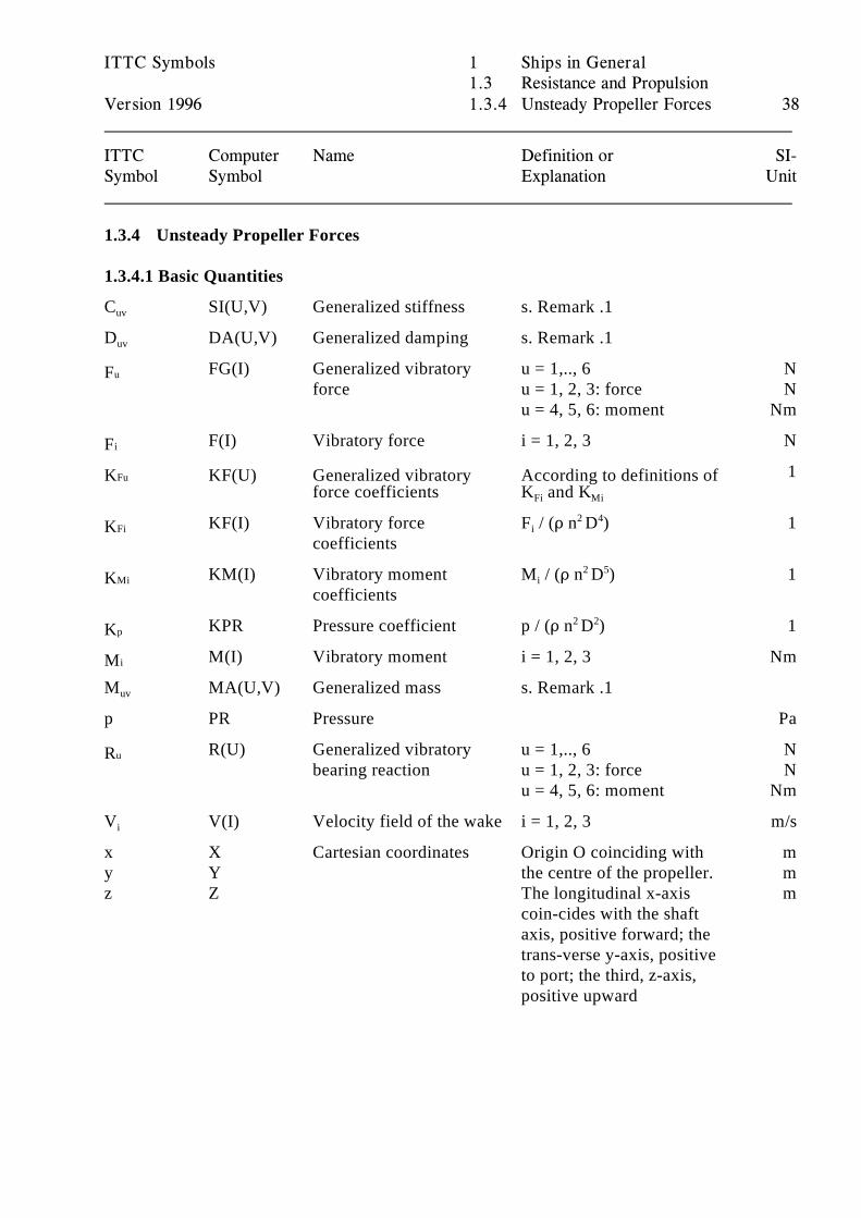
Version 1996 1.3.4 Unsteady Propeller Forces 38
ITTC Computer Name Definition or SI-Symbol Symbol Explanation Unit
1.3.4 Unsteady Propeller Forces
1.3.4.1 Basic Quantities
C SI(U,V) Generalized stiffness s. Remark .1uv
D DA(U,V) Generalized damping s. Remark .1uv
FG(I) Generalized vibratory u = 1,.., 6 NuFforce u = 1, 2, 3: force N
u = 4, 5, 6: moment Nm
F(I) Vibratory force i = 1, 2, 3 NiF1FuK KF(U)
force coefficients K and KFi Mi
Generalized vibratory According to definitions of
KF(I) Vibratory force F / (D n D ) 1FiKcoefficients
i2 4
KM(I) Vibratory moment M / (D n D ) 1MiKcoefficients
i2 5
KPR Pressure coefficient p / (D n D ) 1pK 2 2
M(I) Vibratory moment i = 1, 2, 3 NmiMM MA(U,V) Generalized mass s. Remark .1uv
p PR Pressure Pa
R(U) Generalized vibratory u = 1,.., 6 NuRbearing reaction u = 1, 2, 3: force N
u = 4, 5, 6: moment Nm
V V(I) Velocity field of the wake i = 1, 2, 3 m/si
x X Cartesian coordinates Origin O coinciding with my Y the centre of the propeller. mz Z The longitudinal x-axis m
coin-cides with the shaftaxis, positive forward; thetrans-verse y-axis, positiveto port; the third, z-axis,positive upward
*
*
*̈
*̈ * *
*
ITTC Symbols 1 Ships in General1.3 Resistance and Propulsion
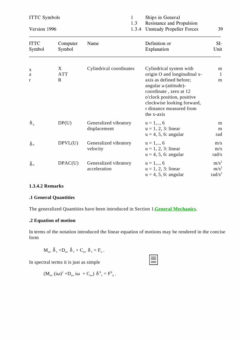
Version 1996 1.3.4 Unsteady Propeller Forces 39
ITTC Computer Name Definition or SI-Symbol Symbol Explanation Unit
X Cylindrical coordinates Cylindrical system with ma ATT origin O and longitudinal x- 1r R axis as defined before; m
x
angular a-(attitude)-coordinate , zero at 12o'clock position, positiveclockwise looking forward,r distance measured fromthe x-axis
u DP(U) Generalized vibratory u = 1,.., 6 mdisplacement u = 1, 2, 3: linear m
u = 4, 5, 6: angular rad
u DPVL(U) Generalized vibratory u = 1,.., 6 m/svelocity u = 1, 2, 3: linear m/s
u = 4, 5, 6: angular rad/s
u DPAC(U) Generalized vibratory u = 1,.., 6 m/sacceleration u = 1, 2, 3: linear m/s
u = 4, 5, 6: angular rad/s
2
2
2
1.3.4.2 Remarks
.1 General Quantities
The generalized Quantities have been introduced in Section 1. General Mechanics. .2 Equation of motion
In terms of the notation introduced the linear equation of motions may be rendered in the conciseform
M +D + C = F .uv v uv v uv v u
In spectral terms it is just as simple
(M (iT) +D iT + C ) = F .uv uv uv v u2 S S
ITTC Symbols 1 Ships in General1.4.3 Manoeuvring and Seakeeping
Version 1996 1.4.1 Manoeuvring 40
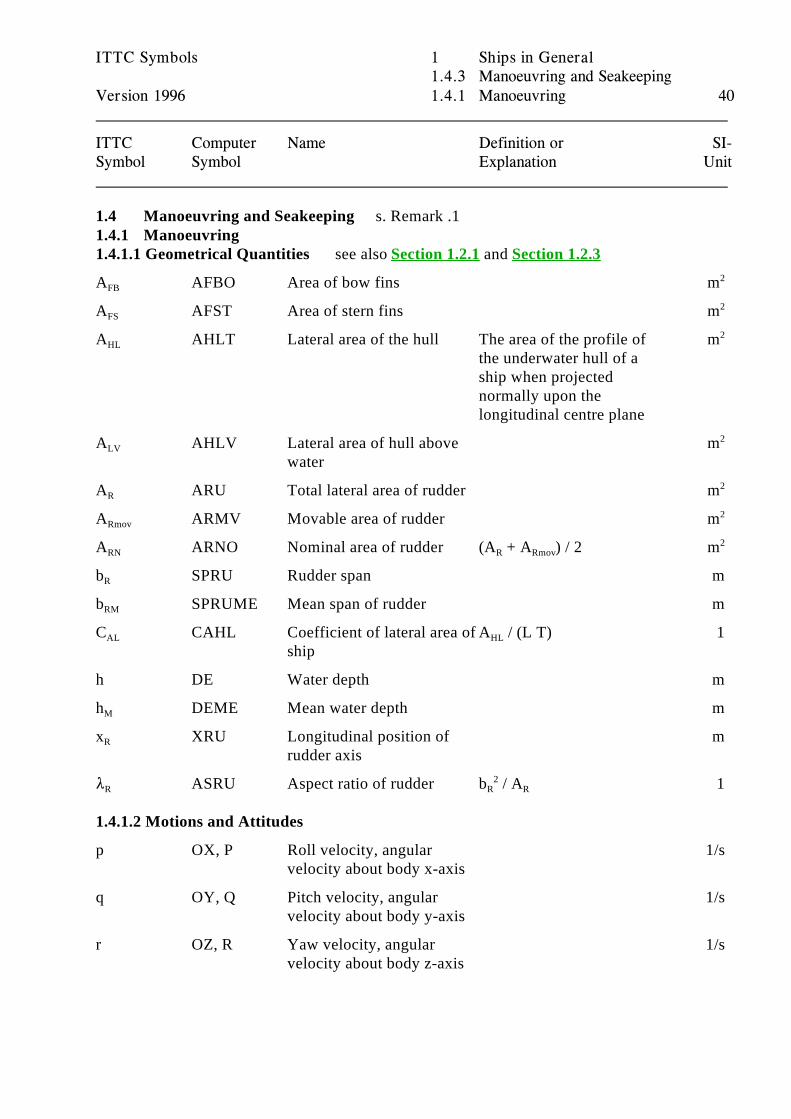
ITTC Computer Name Definition or SI-Symbol Symbol Explanation Unit
1.4 Manoeuvring and Seakeeping s. Remark .11.4.1 Manoeuvring1.4.1.1 Geometrical Quantities see also Section 1.2.1 and Section 1.2.3
A AFBO Area of bow fins mFB2
A AFST Area of stern fins mFS2
A AHLT Lateral area of the hull The area of the profile of mHL
the underwater hull of aship when projectednormally upon thelongitudinal centre plane
2
A AHLV Lateral area of hull above mLV
water
2
A ARU Total lateral area of rudder mR2
A ARMV Movable area of rudder mRmov2
A ARNO Nominal area of rudder (A + A ) / 2 mRN R Rmov2
b SPRU Rudder span mR
b SPRUME Mean span of rudder mRM
C CAHL Coefficient of lateral area of A / (L T) 1AL
shipHL
h DE Water depth m
h DEME Mean water depth mM
x XRU Longitudinal position of mR
rudder axis
8 ASRU Aspect ratio of rudder b / A 1R R R2
1.4.1.2 Motions and Attitudes
p OX, P Roll velocity, angular 1/svelocity about body x-axis
q OY, Q Pitch velocity, angular 1/svelocity about body y-axis
r OZ, R Yaw velocity, angular 1/svelocity about body z-axis
p
q
r
u
v
w
V
ITTC Symbols 1 Ships in General1.4.3 Manoeuvring and Seakeeping
Version 1996 1.4.1 Manoeuvring 41
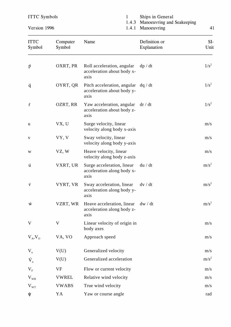
ITTC Computer Name Definition or SI-Symbol Symbol Explanation Unit
OXRT, PR Roll acceleration, angular dp / dt 1/sacceleration about body x-axis
2
OYRT, QR Pitch acceleration, angular dq / dt 1/sacceleration about body y-axis
2
OZRT, RR Yaw acceleration, angular dr / dt 1/sacceleration about body z-axis
2
u VX, U Surge velocity, linear m/svelocity along body x-axis
v VY, V Sway velocity, linear m/svelocity along body y-axis
w VZ, W Heave velocity, linear m/svelocity along body z-axis
VXRT, UR Surge acceleration, linear du / dt m/sacceleration along body x-axis
2
VYRT, VR Sway acceleration, linear dv / dt m/sacceleration along body y-axis
2
VZRT, WR Heave acceleration, linear dw / dt m/sacceleration along body z-axis
2
V V Linear velocity of origin in m/sbody axes
V ,V VA, VO Approach speed m/sA O
V V(U) Generalized velocity m/su
uV(U) Generalized acceleration m/s2
V VF Flow or current velocity m/sF
V VWREL Relative wind velocity m/sWR
V VWABS True wind velocity m/sWT
R YA Yaw or course angle rad
R
ITTC Symbols 1 Ships in General1.4.3 Manoeuvring and Seakeeping
Version 1996 1.4.1 Manoeuvring 42
ITTC Computer Name Definition or SI-Symbol Symbol Explanation Unit
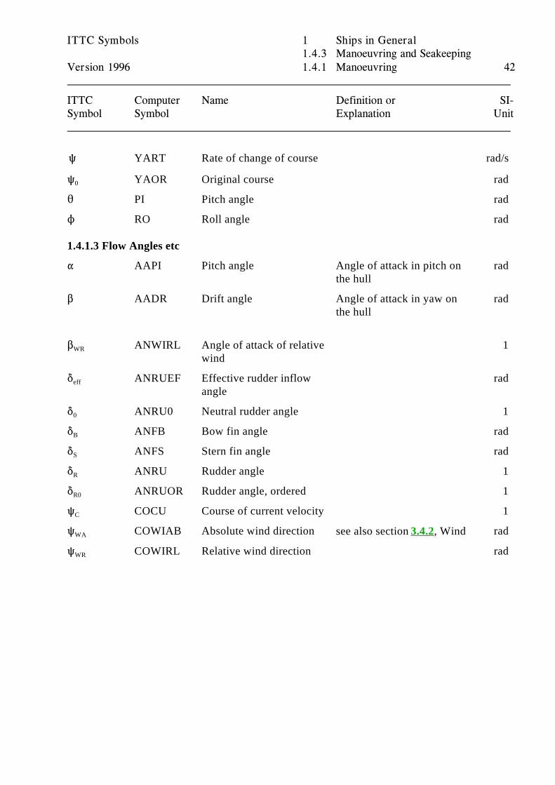
YART Rate of change of course rad/s
R YAOR Original course rad0
2 PI Pitch angle rad
N RO Roll angle rad
1.4.1.3 Flow Angles etc
" AAPI Pitch angle Angle of attack in pitch on radthe hull
$ AADR Drift angle Angle of attack in yaw on radthe hull
$ ANWIRL Angle of attack of relative 1WR
wind
* ANRUEF Effective rudder inflow radeff
angle
* ANRU0 Neutral rudder angle 10
* ANFB Bow fin angle radB
* ANFS Stern fin angle radS
* ANRU Rudder angle 1R
* ANRUOR Rudder angle, ordered 1R0
R COCU Course of current velocity 1C
R COWIAB Absolute wind direction radWA see also section 3.4.2, Wind
R COWIRL Relative wind direction radWR
r r
v v
u u
ITTC Symbols 1 Ships in General1.4.3 Manoeuvring and Seakeeping
Version 1996 1.4.1 Manoeuvring 43
ITTC Computer Name Definition or SI-Symbol Symbol Explanation Unit
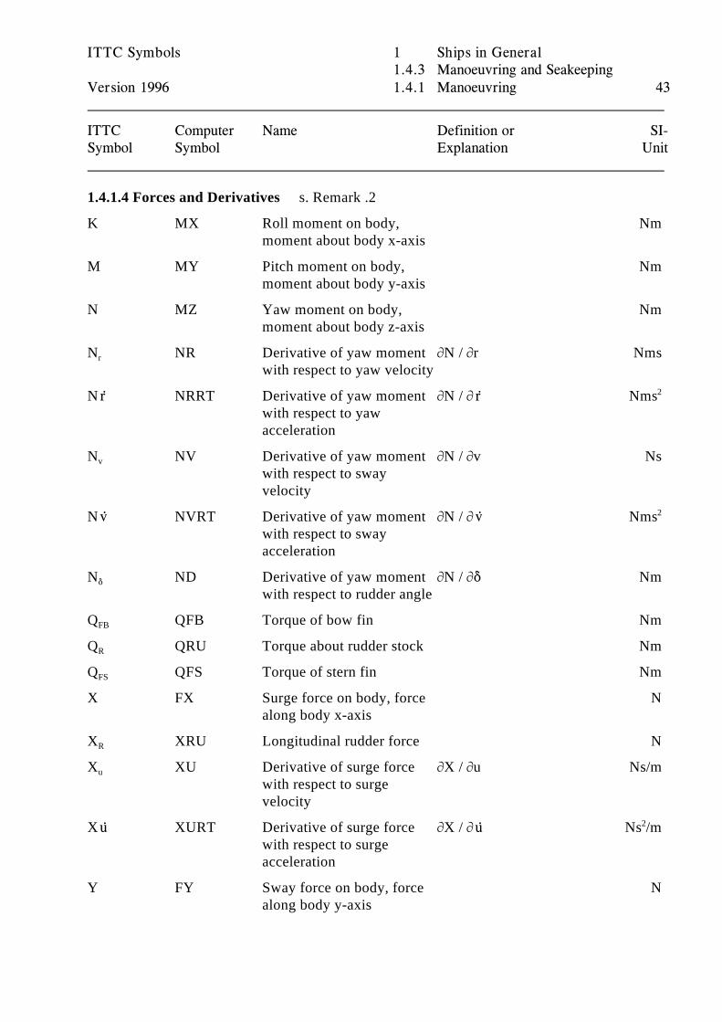
1.4.1.4 Forces and Derivatives s. Remark .2
K MX Roll moment on body, Nmmoment about body x-axis
M MY Pitch moment on body, Nmmoment about body y-axis
N MZ Yaw moment on body, Nmmoment about body z-axis
N NR Derivative of yaw moment MN / Mr Nmsr
with respect to yaw velocity
N NRRT Derivative of yaw moment MN / M Nmswith respect to yawacceleration
2
N NV Derivative of yaw moment MN / Mv Nsv
with respect to swayvelocity
N NVRT Derivative of yaw moment MN / M Nmswith respect to swayacceleration
2
N ND Derivative of yaw moment MN / M* Nm*
with respect to rudder angle
Q QFB Torque of bow fin NmFB
Q QRU Torque about rudder stock NmR
Q QFS Torque of stern fin NmFS
X FX Surge force on body, force Nalong body x-axis
X XRU Longitudinal rudder force NR
X XU Derivative of surge force MX / Mu Ns/mu
with respect to surgevelocity
X XURT Derivative of surge force MX / M Ns /m with respect to surge
acceleration
2
Y FY Sway force on body, force Nalong body y-axis
r r
v v
ITTC Symbols 1 Ships in General1.4.3 Manoeuvring and Seakeeping
Version 1996 1.4.1 Manoeuvring 44
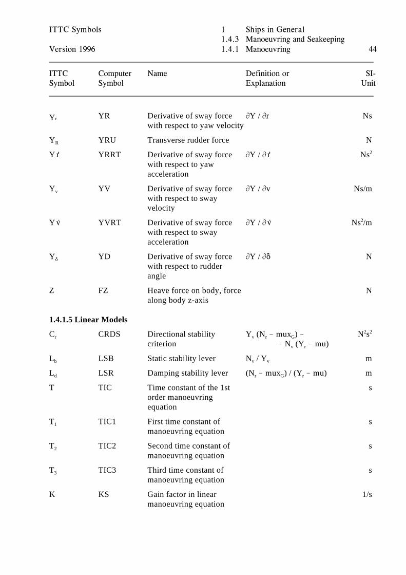
ITTC Computer Name Definition or SI-Symbol Symbol Explanation Unit
YR Derivative of sway force MY / Mr NsrYwith respect to yaw velocity
Y YRU Transverse rudder force NR
Y YRRT Derivative of sway force MY / M Ns with respect to yaw
acceleration
2
Y YV Derivative of sway force MY / Mv Ns/mv
with respect to swayvelocity
Y YVRT Derivative of sway force MY / M Ns /mwith respect to swayacceleration
2
Y YD Derivative of sway force MY / M* N*
with respect to rudder angle
Z FZ Heave force on body, force Nalong body z-axis
1.4.1.5 Linear Models
C CRDS Directional stability Y (N ! mux ) ! N sr
criterion ! N (Y ! mu)v r G
v r
2 2
L LSB Static stability lever N / Y mb v v
L LSR Damping stability lever (N ! mux ) / (Y ! mu) md r G r
T TIC Time constant of the 1st sorder manoeuvringequation
T TIC1 First time constant of s1
manoeuvring equation
T TIC2 Second time constant of s2
manoeuvring equation
T TIC3 Third time constant of s3
manoeuvring equation
K KS Gain factor in linear 1/smanoeuvring equation
ITTC Symbols 1 Ships in General1.4.3 Manoeuvring and Seakeeping
Version 1996 1.4.1 Manoeuvring 45
ITTC Computer Name Definition or SI-Symbol Symbol Explanation Unit
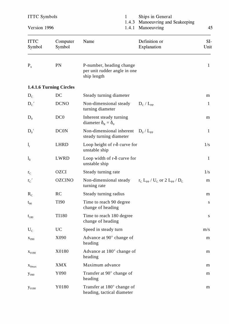
P PN P-number, heading change 1n
per unit rudder angle in oneship length
1.4.1.6 Turning Circles
D DC Steady turning diameter mC
D N DCNO Non-dimensional steady D / L 1C
turning diameterC PP
D DC0 Inherent steady turning m0
diameter * = *R 0
D N DC0N Non-dimensional inherent D / L 10
steady turning diameter0 PP
l LHRD Loop height of r-* curve for 1/sr
unstable ship
l LWRD Loop width of r-* curve for 1*
unstable ship
r OZCI Steady turning rate 1/sC
r N OZCINO Non-dimensional steady r L / U or 2 L / D mC
turning rateC PP C PP C
R RC Steady turning radius mC
t TI90 Time to reach 90 degree s90
change of heading
t TI180 Time to reach 180 degree s180
change of heading
U UC Speed in steady turn m/sC
x X090 Advance at 90E change of m090
heading
x X0180 Advance at 180E change of m0180
heading
x XMX Maximum advance m0max
y Y090 Transfer at 90E change of m090
heading
y Y0180 Transfer at 180E change of m0180
heading, tactical diameter
ITTC Symbols 1 Ships in General1.4.3 Manoeuvring and Seakeeping
Version 1996 1.4.1 Manoeuvring 46
ITTC Computer Name Definition or SI-Symbol Symbol Explanation Unit
y Y0MX Maximum transfer m0max
$ DRCI Drift angle at steady turning radC
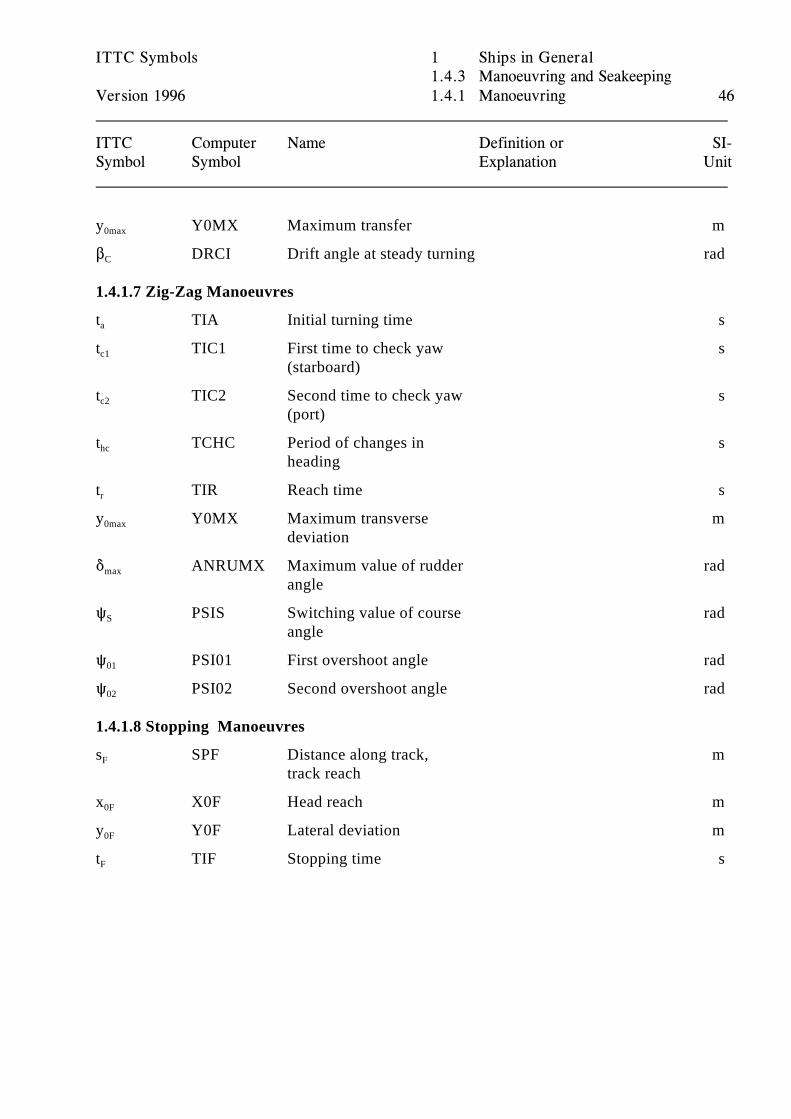
1.4.1.7 Zig-Zag Manoeuvres
t TIA Initial turning time sa
t TIC1 First time to check yaw sc1
(starboard)
t TIC2 Second time to check yaw sc2
(port)
t TCHC Period of changes in shc
heading
t TIR Reach time sr
y Y0MX Maximum transverse m0max
deviation
* ANRUMX Maximum value of rudder radmax
angle
R PSIS Switching value of course radS
angle
R PSI01 First overshoot angle rad01
R PSI02 Second overshoot angle rad02
1.4.1.8 Stopping Manoeuvres
s SPF Distance along track, mF
track reach
x X0F Head reach m0F
y Y0F Lateral deviation m0F
t TIF Stopping time sF
ITTC Symbols 1 Ships in General1.4.3 Manoeuvring and Seakeeping
Version 1996 1.4.1 Manoeuvring 47
ITTC Computer Name Definition or SI-Symbol Symbol Explanation Unit
1.4.1.9 Remarks
.1 Solid Body Motions
The whole Chapter 1.4 on Manoeuvring and Seakeeping relies heavily on the Section 1 on GeneralMechanics, Chapter 1.2 on Solid Body Mechanics in particular. Members of the ManoeuvringCommittee are strongly urged to suggest further improvements in this section.
.2 Derivatives
The traditional notation for the "stability" derivatives is not very efficient and not in accordancewith the notation outlined in Section 3 on General Mechanics. Instead of completely denoting theconcepts of generalized hydrodynamic damping and inertia, respectively, by adequate symbols, thetraditional symbols indicate some measuring procedures for the components.
ITTC Symbols 1 Ships in General1.4 Manoeuvring and Seakeeping
Version 1996 1.4.2 Seakeeping 48
ITTC Computer Name Definition or SI-Symbol Symbol Explanation Unit
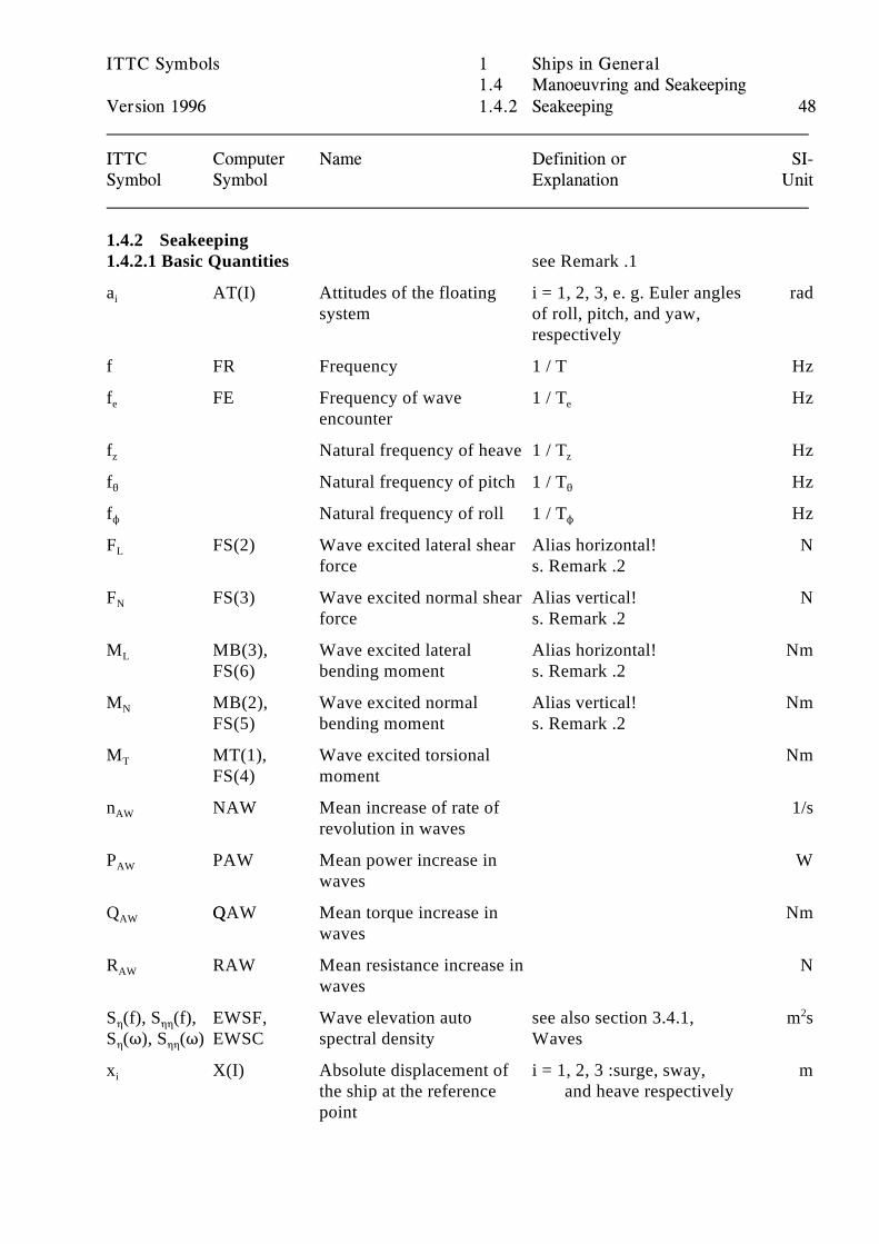
1.4.2 Seakeeping1.4.2.1 Basic Quantities see Remark .1
a AT(I) Attitudes of the floating i = 1, 2, 3, e. g. Euler angles radi
system of roll, pitch, and yaw,respectively
f FR Frequency 1 / T Hz
f FE Frequency of wave 1 / T Hze
encountere
f Natural frequency of heave 1 / T Hzz z
f Natural frequency of pitch 1 / T Hz2 2
f Natural frequency of roll 1 / T HzN N
F FS(2) Wave excited lateral shear Alias horizontal! NL
force s. Remark .2
F FS(3) Wave excited normal shear Alias vertical! NN
force s. Remark .2
M MB(3), Wave excited lateral Alias horizontal! NmL
FS(6) bending moment s. Remark .2
M MB(2), Wave excited normal Alias vertical! NmN
FS(5) bending moment s. Remark .2
M MT(1), Wave excited torsional NmT
FS(4) moment
n NAW Mean increase of rate of 1/sAW
revolution in waves
P PAW Mean power increase in WAW
waves
Q QQAW Mean torque increase in NmAW
waves
R RAW Mean resistance increase in NAW
waves
S (f), S (f), EWSF, Wave elevation auto see also section 3.4.1, m s0 00
S (T), S (T) EWSC spectral density Waves0 00
2
x X(I) Absolute displacement of i = 1, 2, 3 :surge, sway, mi
the ship at the reference and heave respectivelypoint
ITTC Symbols 1 Ships in General1.4 Manoeuvring and Seakeeping
Version 1996 1.4.2 Seakeeping 49
ITTC Computer Name Definition or SI-Symbol Symbol Explanation Unit
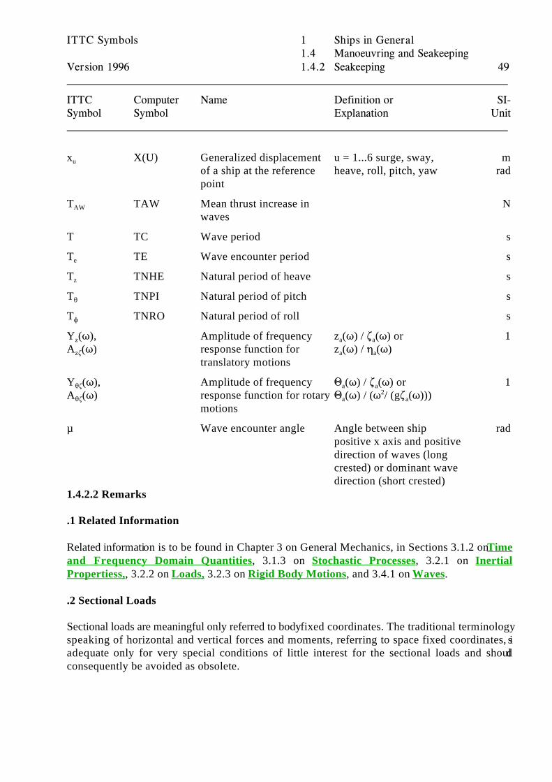
x X(U) Generalized displacement u = 1...6 surge, sway, mu
of a ship at the reference heave, roll, pitch, yaw radpoint
T TAW Mean thrust increase in NAW
waves
T TC Wave period s
T TE Wave encounter period se
T TNHE Natural period of heave sz
T TNPI Natural period of pitch s2
T TNRO Natural period of roll sN
Y (T), Amplitude of frequency z (T) / . (T) or 1z
A (T) response function for z (T) / 0 (T)z.
translatory motions
a a
a a
Y (T), Amplitude of frequency 1 (T) / . (T) or 12.
A (T) response function for rotary 1 (T) / (T / (g. (T)))2.
motions
a a
a a2
µ Wave encounter angle Angle between ship radpositive x axis and positivedirection of waves (longcrested) or dominant wavedirection (short crested)
1.4.2.2 Remarks
.1 Related Information
Related information is to be found in Chapter 3 on General Mechanics, in Sections 3.1.2 on Timeand Frequency Domain Quantities, 3.1.3 on Stochastic Processes, 3.2.1 on InertialPropertiess,, 3.2.2 on Loads, 3.2.3 on Rigid Body Motions, and 3.4.1 on Waves.
.2 Sectional Loads
Sectional loads are meaningful only referred to body fixed coordinates. The traditional terminologyspeaking of horizontal and vertical forces and moments, referring to space fixed coordinates, isadequate only for very special conditions of little interest for the sectional loads and shouldconsequently be avoided as obsolete.
ITTC Symbols 2 Special Craft2.1 Planing and Semi-Displacement Vessels
Version 1996 2.1.1 Geometry and Hydrostatics 50
ITTC Computer Name Definition or SI-Symbol Symbol Explanation Unit
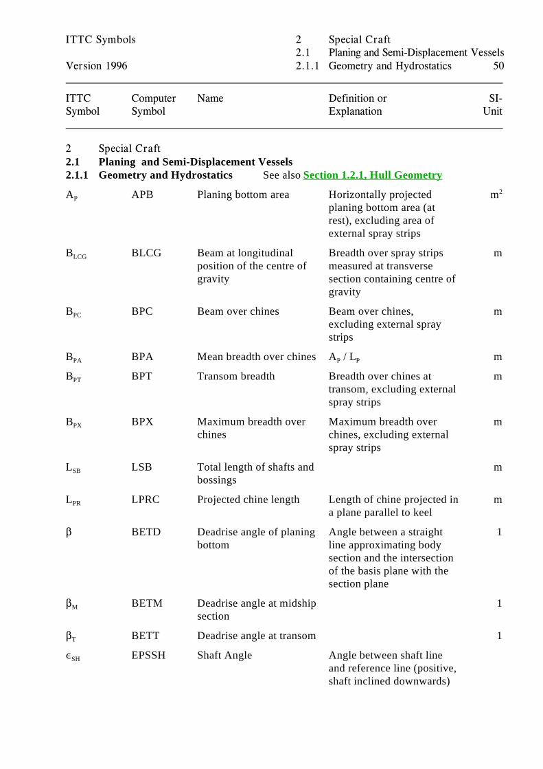
2 Special Craft2.1 Planing and Semi-Displacement Vessels 2.1.1 Geometry and Hydrostatics See also Section 1.2.1, Hull Geometry
A APB Planing bottom area Horizontally projected mP
planing bottom area (atrest), excluding area ofexternal spray strips
2
B BLCG Beam at longitudinal Breadth over spray strips mLCG
position of the centre of measured at transversegravity section containing centre of
gravity
B BPC Beam over chines Beam over chines, mPC
excluding external spraystrips
B BPA Mean breadth over chines A / L mPA P P
B BPT Transom breadth Breadth over chines at mPT
transom, excluding externalspray strips
B BPX Maximum breadth over Maximum breadth over mPX
chines chines, excluding externalspray strips
L LSB Total length of shafts and mSB
bossings
L LPRC Projected chine length Length of chine projected in mPR
a plane parallel to keel
$ BETD Deadrise angle of planing Angle between a straight 1bottom line approximating body
section and the intersectionof the basis plane with thesection plane
$ BETM Deadrise angle at midship 1M
section
$ BETT Deadrise angle at transom 1T
, EPSSH Shaft Angle Angle between shaft lineSH
and reference line (positive,shaft inclined downwards)
ITTC Symbols 2 Special Craft2.1 Planing and Semi-Displacement Vessels
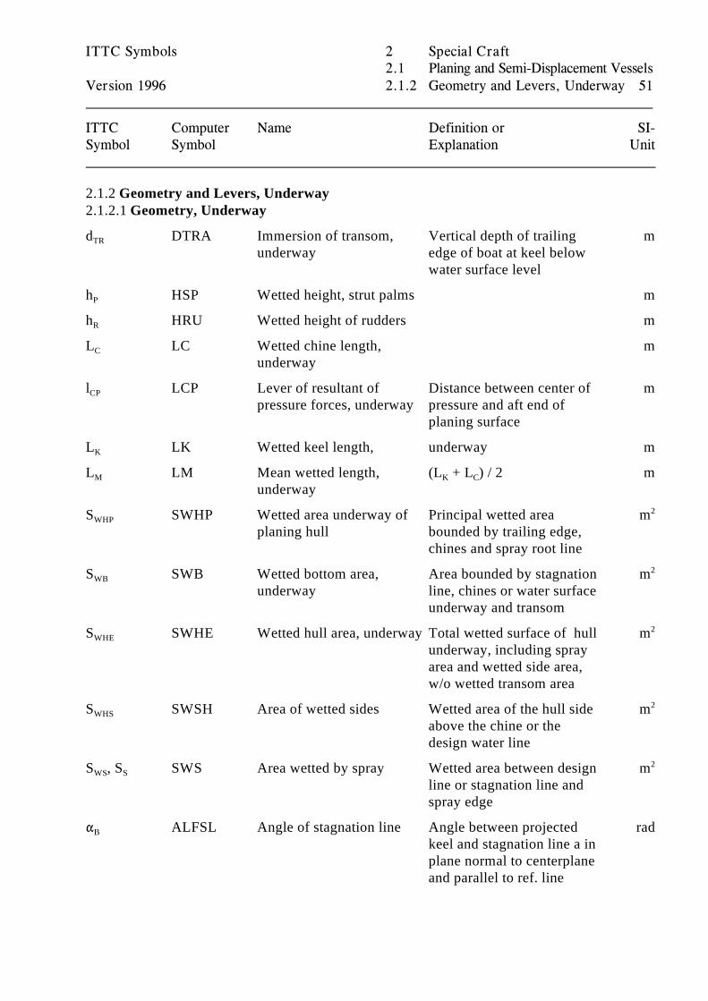
Version 1996 2.1.2 Geometry and Levers, Underway 51
ITTC Computer Name Definition or SI-Symbol Symbol Explanation Unit
2.1.2 Geometry and Levers, Underway2.1.2.1 Geometry, Underway
d DTRA Immersion of transom, Vertical depth of trailing mTR
underway edge of boat at keel belowwater surface level
h HSP Wetted height, strut palms mP
h HRU Wetted height of rudders mR
L LC Wetted chine length, mC
underway
l LCP Lever of resultant of Distance between center of mCP
pressure forces, underway pressure and aft end ofplaning surface
L LK Wetted keel length, underway mK
L LM Mean wetted length, (L + L ) / 2 mM
underwayK C
S SWHP Wetted area underway of Principal wetted area mWHP
planing hull bounded by trailing edge,chines and spray root line
2
S SWB Wetted bottom area, Area bounded by stagnation mWB
underway line, chines or water surfaceunderway and transom
2
S SWHE Wetted hull area, underway Total wetted surface of hull mWHE
underway, including sprayarea and wetted side area,w/o wetted transom area
2
S SWSH Area of wetted sides Wetted area of the hull side mWHS
above the chine or thedesign water line
2
S , S SWS Area wetted by spray Wetted area between design mWS S
line or stagnation line andspray edge
2
" ALFSL Angle of stagnation line Angle between projected radB
keel and stagnation line a inplane normal to centerplaneand parallel to ref. line
ITTC Symbols 2 Special Craft2.1 Planing and Semi-Displacement Vessels
Version 1996 2.1.2 Geometry and Levers, Underway 52
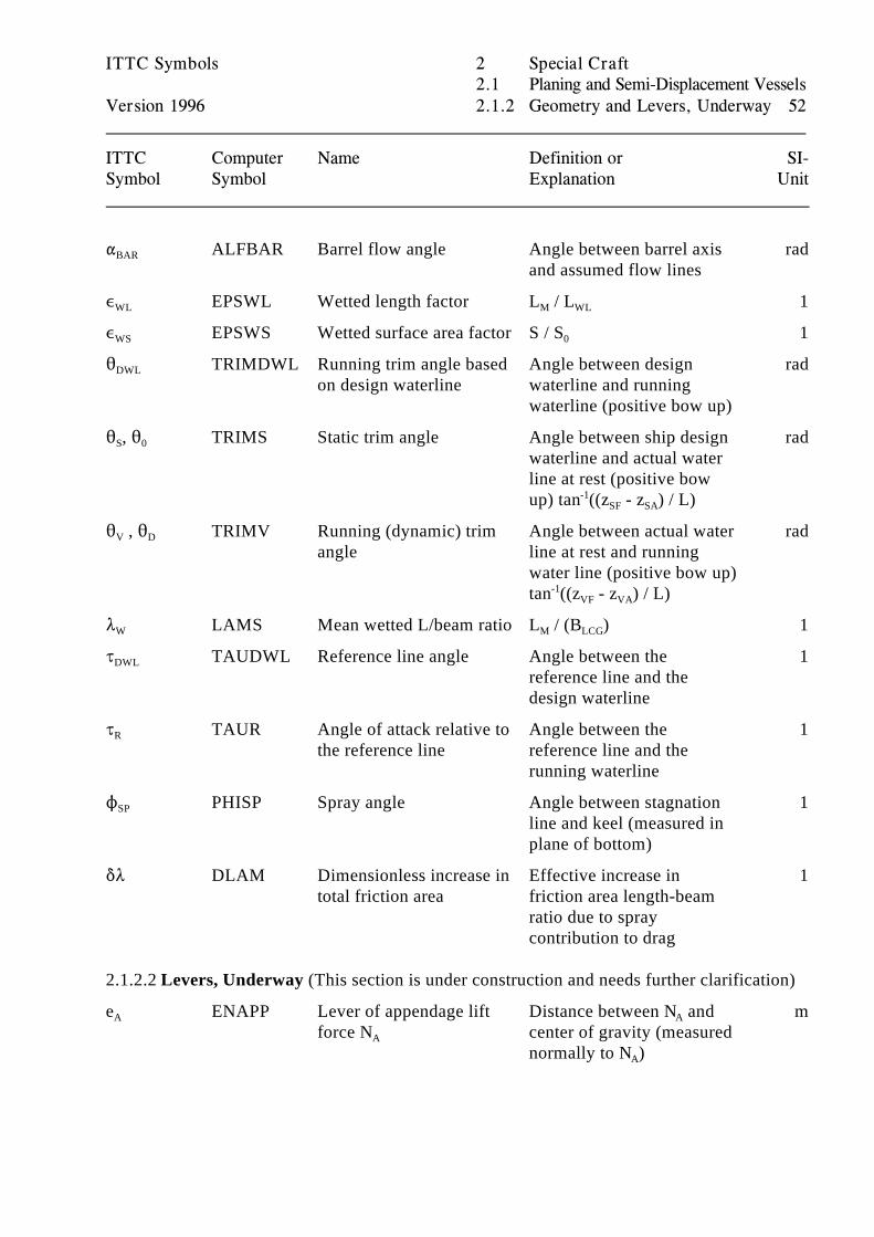
ITTC Computer Name Definition or SI-Symbol Symbol Explanation Unit
" ALFBAR Barrel flow angle Angle between barrel axis radBAR
and assumed flow lines
, EPSWL Wetted length factor L / L 1WL M WL
, EPSWS Wetted surface area factor S / S 1WS 0
2 TRIMDWL Running trim angle based Angle between design radDWL
on design waterline waterline and runningwaterline (positive bow up)
2 , 2 TRIMS Static trim angle Angle between ship design radS 0
waterline and actual waterline at rest (positive bowup) tan ((z - z ) / L)-1
SF SA
2 , 2 TRIMV Running (dynamic) trim Angle between actual water radV D
angle line at rest and runningwater line (positive bow up)tan ((z - z ) / L)-1
VF VA
8 LAMS Mean wetted L/beam ratio L / (B ) 1W M LCG
J TAUDWL Reference line angle Angle between the 1DWL
reference line and thedesign waterline
J TAUR Angle of attack relative to Angle between the 1R
the reference line reference line and therunning waterline
N PHISP Spray angle Angle between stagnation 1SP
line and keel (measured inplane of bottom)
*8 DLAM Dimensionless increase in Effective increase in 1total friction area friction area length-beam
ratio due to spraycontribution to drag
2.1.2.2 Levers, Underway (This section is under construction and needs further clarification)
e ENAPP Lever of appendage lift Distance between N and mA
force N center of gravity (measuredA
A
normally to N )A
ITTC Symbols 2 Special Craft2.1 Planing and Semi-Displacement Vessels
Version 1996 2.1.2 Geometry and Levers, Underway 53
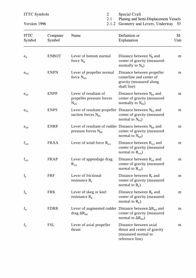
ITTC Computer Name Definition or SI-Symbol Symbol Explanation Unit
e ENBOT Lever of bottom normal Distance between N and mB
force N center of gravity (measuredB
B
normally to N )B
e ENPN Lever of propeller normal Distance between propeller mPN
force N centerline and center ofPN
gravity (measured alongshaft line)
e ENPP Lever of resultant of Distance between N and mPP
propeller pressure forces center of gravity (measuredN normally to N )PP
PP
PP
e ENPS Lever of resultant propeller Distance between N and mPS
suction forces N center of gravity (measuredPS
PS
normal to N )PS
e ENRP Lever of resultant of rudder Distance between N and mRP
pressure forces N center of gravity (measuredRP
RP
normal to N )RP
f FRAA Lever of wind force R Distance between R and mAA AA AA
center of gravity (measurednormal to R )AA
f FRAP Lever of appendage drag Distance between R and mAP
R center of gravity (measuredAP
AP
normal to R )AP
f FRF Lever of frictional Distance between R and mF
resistance R center of gravity (measuredF
F
normal to R )F
f FRK Lever of skeg or keel Distance between R and mK
resistance R center of gravity (measuredK
K
normal to R )K
f FDRR Lever of augmented rudder Distance between )R and mR
drag )R center of gravity (measuredRP
RP
normal to )R )RP
f FSL Lever of axial propeller Distance between axial mS
thrust thrust and center of gravity(measured normal toreference line)
ITTC Symbols 2 Special Craft2.1 Planing and Semi-Displacement Vessels
Version 1996 2.1.3 Resistance and Propulsion 54
ITTC Computer Name Definition or SI-Symbol Symbol Explanation Unit
2.1.3 Resistance and Propulsion See also Sections 1.3.1 on Hull Resistance
C CL0D Lift coefficient for zero ) / (B q) 1Lo
deadriseCG
2
C CLBET Lift coefficient for deadrise ) / (B q) 1L$
surfaceCG
2
C CSP Froude number based on V / (B g) 1V
breadthCG
1/2
C CDL Load coefficient ) / (B D g ) 1) CG3
L LVD Vertical component of NVHD
hydrodynamic lift
L LVS Hydrostatic lift Due to buoyancy NVS
F FTAPP Appendage drag force Drag forces arising from NTA
(parallel to reference line) appendages inclined toflow, assumed to actparallel to the reference line
F FTBOT Bottom frictional force Viscous component of NTB
(parallel to reference line) bottom drag forces assumedacting parallel to thereference line
F FTKL Keel or skeg drag force Drag forces arising from NTK
(parallel to reference line) keel or skeg, assumed to actparallel to the reference line
F FTRP Additional rudder drag Drag forces arising from NTRP
force (parallel to reference influence of propeller wakeline) on the rudder assumed to
act parallel to the referenceline
N NAPP Appendage lift force Lift forces arising from NA
(normal to reference line) appendages inclined toflow, assumed to actnormally to reference line
N NBOT Bottom normal force Resultant of pressure and NB
(normal to reference line) buoyant forces assumedacting normally to thereference line
ITTC Symbols 2 Special Craft2.1 Planing and Semi-Displacement Vessels
Version 1996 2.1.3 Resistance and Propulsion 55
ITTC Computer Name Definition or SI-Symbol Symbol Explanation Unit
N NPP Propeller pressure force Resultant of propeller NPP
(normal to reference line) pressure forces actingnormally to the referenceline
N NPS Propeller suction force Resultant of propeller NPS
(normal to reference line) suction forces actingnormally to the referenceline
N NRP Rudder pressure force Resultant of rudder pressureRP
(normal to reference line) forces acting normally tothe reference line
R RKEEL Keel drag NK
R RPI Induced drag g D L tg J NB
R RPAR Parasitc drag Drag due to inlet and outlet NPAR
openings
R RSP Pressure component of NPS
spray drag
R RSV Viscous component of C S q NVS
spray dragF WS S
V VBM Mean bottom velocity Mean velocity over bottom m/sBM
of the hull
V VSP Spray velocity Relative velocity between m/sSP
hull and spray in directionof the spray
2.1.3. Remarks
.1 Force orientationsAs a rule, the symbol R (resistance ) is used when forces are directed horizontally, parallel to boatvelocity and V when forces are directed vertically, normal to the boat velocity. Further, symbolsN (normal) and F or D (tangential) are used for forces acting normally and tangentially to theF T F
reference line (keel or mean buttock line). The SaT Group prefers the use of F for the tangentialT
forces, but the standard references (Savitsky and Hadler) use the second set of symbols.
.2 Reference lineThe reference line line must be defined. It is ususally the keel line or mean buttock line.
ITTC Symbols 2 Special Craft2.2 Multi-Hull Vessels
Version 1996 2.2.1 Geometry and Hydrostatics 56
ITTC Computer Name Definition or SI-Symbol Symbol Explanation Unit
2.2 Multi-Hull Vessels
2.2.1 Geometry and Hydrostatics See also Section 1.2.1, Hull Geometry
A AIA Strut-hull intersection area mI2
B BB Box beam Beam of main deck mB
B BS Hull spacing Distance between hull mS
center lines
B BTUN Tunnel width Minimal distance of the mTV
demihulls at the waterline
D DHUL Hull diameter Diameter of axis symmetric mH
submerged hulls
DX Hull diameter at the mXDlongitudinal position "X"
H HCLDK Deck clearance Minimum clearance of wet mDK
deck from water surface atrest
H HSS Strut submerged depth Depth of strut from still mSS
water line to strut-hullintersection
i ANENIN Half angle of entrance at Angle of inner water line radEI
tunnel (inner) side with reference to centre lineof demihull
i ANENOU Half angle of entrance at Angle of outer water line radEO
outer side with reference to centre lineof demihull
L LCH Length of center section of Length of prismatic part of mCH
hull hull
L LCS Length of center section of Length of prismatic part of mCS
strut strut
L LH Box length Length of main deck mH
L LNH Length of nose section of Length of nose section of mNH
hull hull with variable diameter
L LNS Length of nose section of Length of nose section of mNS
strut strut with variable thickness
ITTC Symbols 2 Special Craft2.2 Multi-Hull Vessels
Version 1996 2.2.1 Geometry and Hydrostatics 57
ITTC Computer Name Definition or SI-Symbol Symbol Explanation Unit
L LS Strut length Length of strut from leading mS
to trailing edge
L LSH Length of submerged hull mSH
t TSTR Maximum thickness of strut ms
ITTC Symbols 2 Special Craft2.2 Multi-Hull Vessels
Version 1996 2.2.2 Resistance and Propulsion 58
ITTC Computer Name Definition or SI-Symbol Symbol Explanation Unit
2.2.2 Resistance and Propulsion
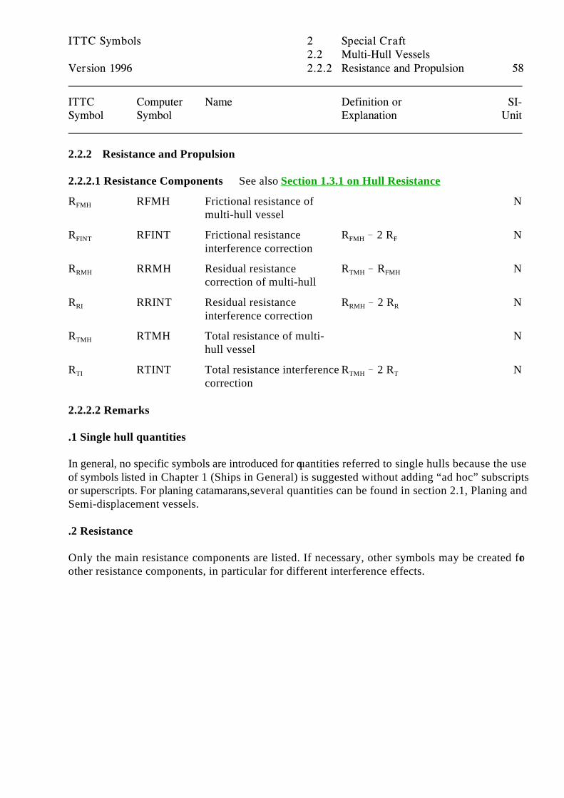
2.2.2.1 Resistance Components See also Section 1.3.1 on Hull Resistance
R RFMH Frictional resistance of NFMH
multi-hull vessel
R RFINT Frictional resistance R ! 2 R NFINT
interference correctionFMH F
R RRMH Residual resistance R ! R NRMH
correction of multi-hull TMH FMH
R RRINT Residual resistance R ! 2 R NRI
interference correctionRMH R
R RTMH Total resistance of multi- NTMH
hull vessel
R RTINT Total resistance interference R ! 2 R NTI
correctionTMH T
2.2.2.2 Remarks
.1 Single hull quantities
In general, no specific symbols are introduced for quantities referred to single hulls because the useof symbols listed in Chapter 1 (Ships in General) is suggested without adding “ad hoc” subscriptsor superscripts. For planing catamarans, several quantities can be found in section 2.1, Planing andSemi-displacement vessels.
.2 Resistance
Only the main resistance components are listed. If necessary, other symbols may be created forother resistance components, in particular for different interference effects.
ITTC Symbols 2 Special Craft2.3 Hydrofoil Boats
Version 1996 2.3.1 Geometry and Hydrostatics 59
ITTC Computer Name Definition or SI-Symbol Symbol Explanation Unit
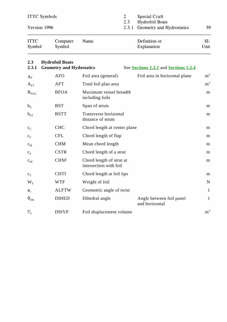
2.3 Hydrofoil Boats2.3.1 Geometry and Hydostatics See Sections 1.2.1 and Sections 1.2.4
AFO Foil area (general) Foil area in horizontal plane mFA 2
A AFT Total foil plan area mFT2
B BFOA Maximum vessel breadth mFOA
including foils
b BST Span of struts mS
b BSTT Transverse horizontal mST
distance of struts
c CHC Chord length at center plane mC
c CFL Chord length of flap mF
c CHM Mean chord length mM
c CSTR Chord length of a strut mS
c CHSF Chord length of strut at mSF
intersection with foil
c CHTI Chord length at foil tips mT
W WTF Weight of foil NF
" ALFTW Geometric angle of twist 1c
2 DIHED Dihedral angle Angle between foil panel 1DH
and horizontal
L DISVF Foil displacement volume mF3
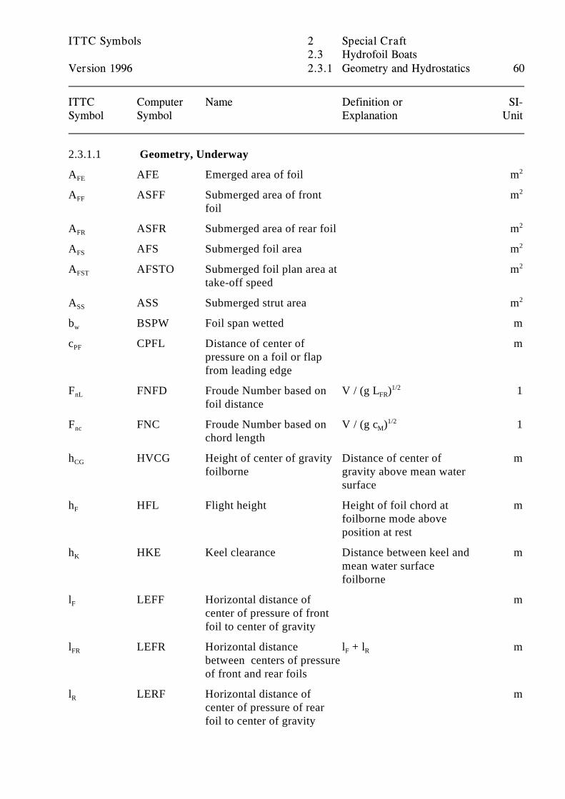
ITTC Symbols 2 Special Craft2.3 Hydrofoil Boats
Version 1996 2.3.1 Geometry and Hydrostatics 60
ITTC Computer Name Definition or SI-Symbol Symbol Explanation Unit
2.3.1.1 Geometry, Underway
A AFE Emerged area of foil mFE2
A ASFF Submerged area of front mFF
foil
2
A ASFR Submerged area of rear foil mFR2
A AFS Submerged foil area mFS2
A AFSTO Submerged foil plan area at mFST
take-off speed
2
A ASS Submerged strut area mSS2
b BSPW Foil span wetted mw
c CPFL Distance of center of mPF
pressure on a foil or flapfrom leading edge
F FNFD Froude Number based on V / (g L ) 1nL
foil distanceFR
1/2
F FNC Froude Number based on V / (g c ) 1nc
chord lengthM
1/2
h HVCG Height of center of gravity Distance of center of mCG
foilborne gravity above mean watersurface
h HFL Flight height Height of foil chord at mF
foilborne mode aboveposition at rest
h HKE Keel clearance Distance between keel and mK
mean water surfacefoilborne
l LEFF Horizontal distance of mF
center of pressure of frontfoil to center of gravity
l LEFR Horizontal distance l + l mFR
between centers of pressureof front and rear foils
F R
l LERF Horizontal distance of mR
center of pressure of rearfoil to center of gravity
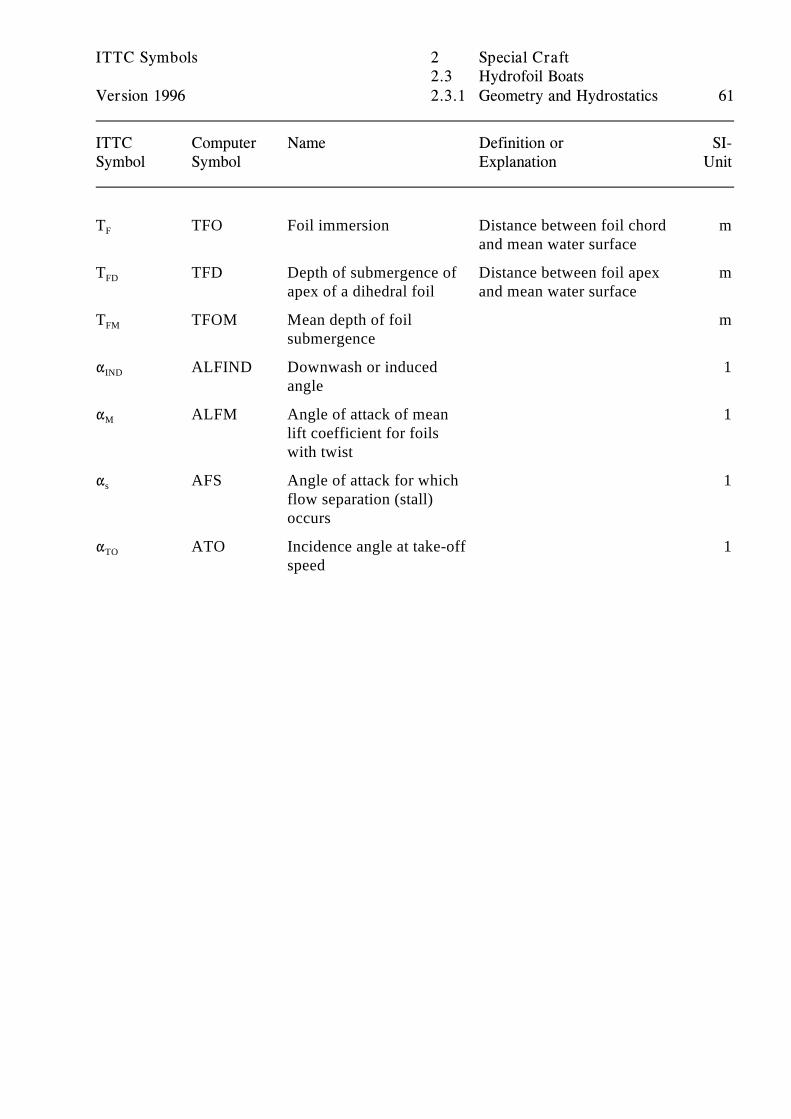
ITTC Symbols 2 Special Craft2.3 Hydrofoil Boats
Version 1996 2.3.1 Geometry and Hydrostatics 61
ITTC Computer Name Definition or SI-Symbol Symbol Explanation Unit
T TFO Foil immersion Distance between foil chord mF
and mean water surface
T TFD Depth of submergence of Distance between foil apex mFD
apex of a dihedral foil and mean water surface
T TFOM Mean depth of foil mFM
submergence
" ALFIND Downwash or induced 1IND
angle
" ALFM Angle of attack of mean 1M
lift coefficient for foils with twist
" AFS Angle of attack for which 1s
flow separation (stall)occurs
" ATO Incidence angle at take-off 1TO
speed
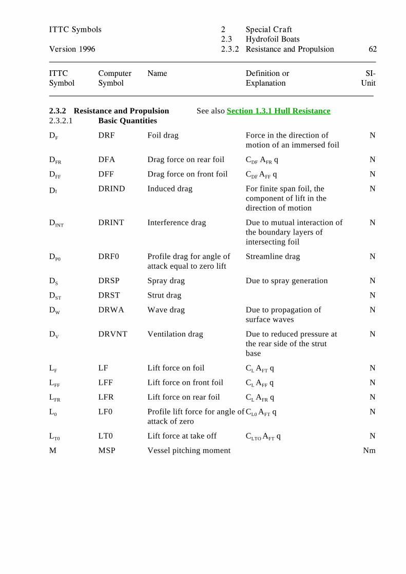
ITTC Symbols 2 Special Craft2.3 Hydrofoil Boats
Version 1996 2.3.2 Resistance and Propulsion 62
ITTC Computer Name Definition or SI-Symbol Symbol Explanation Unit
2.3.2 Resistance and Propulsion See also Section 1.3.1 Hull Resistance2.3.2.1 Basic Quantities
D DRF Foil drag Force in the direction of NF
motion of an immersed foil
D DFA Drag force on rear foil C A q NFR DF FR
D DFF Drag force on front foil C A q NFF DF FF
DRIND Induced drag For finite span foil, the NIDcomponent of lift in thedirection of motion
D DRINT Interference drag Due to mutual interaction of NINT
the boundary layers ofintersecting foil
D DRF0 Profile drag for angle of Streamline drag NP0
attack equal to zero lift
D DRSP Spray drag Due to spray generation NS
D DRST Strut drag NST
D DRWA Wave drag Due to propagation of NW
surface waves
D DRVNT Ventilation drag Due to reduced pressure at NV
the rear side of the strutbase
L LF Lift force on foil C A q NF L FT
L LFF Lift force on front foil C A q NFF L FF
L LFR Lift force on rear foil C A q NFR L FR
L LF0 Profile lift force for angle of C A q N0
attack of zeroL0 FT
L LT0 Lift force at take off C A q NT0 LTO FT
M MSP Vessel pitching moment Nm
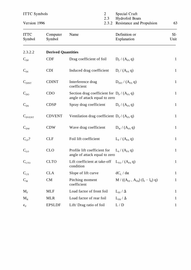
ITTC Symbols 2 Special Craft2.3 Hydrofoil Boats
Version 1996 2.3.2 Resistance and Propulsion 63
ITTC Computer Name Definition or SI-Symbol Symbol Explanation Unit
2.3.2.2 Derived Quantities
C CDF Drag coefficient of foil D / (A q) 1DF F FS
C CDI Induced drag coefficient D / (A q) 1DI I FS
C CDINT Interference drag D / (A q) 1DINT
coefficientINT FS
C CDO Section drag coefficient for D / (A q) 1DO
angle of attack equal to zeroP FS
C CDSP Spray drag coefficient D / (A q) 1DS S FS
C CDVENT Ventilation drag coefficient D / (A q) 1DVENT V FS
C CDW Wave drag coefficient D / (A q) 1DW W FS
C ? CLF Foil lift coefficient L / (A q) 1LF F FS
C CLO Profile lift coefficient for L / (A q) 1LO
angle of attack equal to zero0 FS
C CLTO Lift coefficient at take-off L / (A q) 1LTO
conditionTO FS
C CLA Slope of lift curve dC / d" 1LX L
C CM Pitching moment M / ((A A ) (l ! l ) q) 1M
coefficientFF + FR F R
M MLF Load factor of front foil L / ) 1F FF
M MLR Load factor of rear foil L / ) 1R FR
, EPSLDF Lift/ Drag ratio of foil L / D 1F
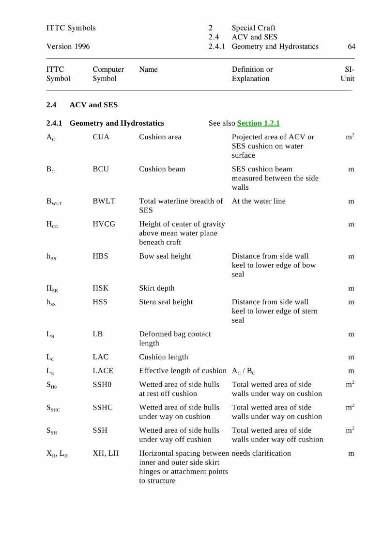
ITTC Symbols 2 Special Craft2.4 ACV and SES
Version 1996 2.4.1 Geometry and Hydrostatics 64
ITTC Computer Name Definition or SI-Symbol Symbol Explanation Unit
2.4 ACV and SES
2.4.1 Geometry and Hydrostatics See also Section 1.2.1
A CUA Cushion area Projected area of ACV or mC
SES cushion on watersurface
2
B BCU Cushion beam SES cushion beam mC
measured between the sidewalls
B BWLT Total waterline breadth of At the water line mWLT
SES
H HVCG Height of center of gravity mCG
above mean water planebeneath craft
h HBS Bow seal height Distance from side wall mBS
keel to lower edge of bowseal
H HSK Skirt depth mSK
h HSS Stern seal height Distance from side wall mSS
keel to lower edge of sternseal
L LB Deformed bag contact mB
length
L LAC Cushion length mC
L LACE Effective length of cushion A / B mE C C
S SSH0 Wetted area of side hulls Total wetted area of side mH0
at rest off cushion walls under way on cushion
2
S SSHC Wetted area of side hulls Total wetted area of side mSHC
under way on cushion walls under way on cushion
2
S SSH Wetted area of side hulls Total wetted area of side mSH
under way off cushion walls under way off cushion
2
X , L XH, LH Horizontal spacing between needs clarification mH H
inner and outer side skirthinges or attachment pointsto structure
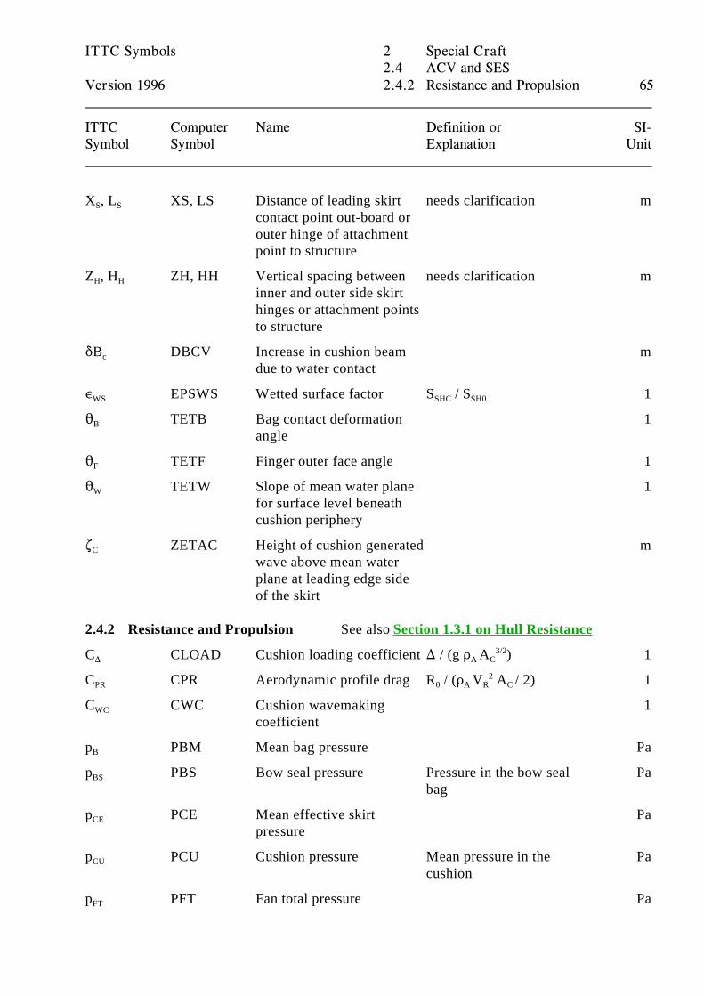
ITTC Symbols 2 Special Craft2.4 ACV and SES
Version 1996 2.4.2 Resistance and Propulsion 65
ITTC Computer Name Definition or SI-Symbol Symbol Explanation Unit
X , L XS, LS Distance of leading skirt needs clarification mS S
contact point out-board orouter hinge of attachmentpoint to structure
Z , H ZH, HH Vertical spacing between needs clarification mH H
inner and outer side skirthinges or attachment pointsto structure
*B DBCV Increase in cushion beam mc
due to water contact
, EPSWS Wetted surface factor S / S 1WS SHC SH0
2 TETB Bag contact deformation 1B
angle
2 TETF Finger outer face angle 1F
2 TETW Slope of mean water plane 1W
for surface level beneathcushion periphery
. ZETAC Height of cushion generated mC
wave above mean waterplane at leading edge sideof the skirt
2.4.2 Resistance and Propulsion See also Section 1.3.1 on Hull Resistance
C CLOAD Cushion loading coefficient ) / (g D A ) 1) A C3/2
C CPR Aerodynamic profile drag R / (D V A / 2) 1PR 0 A R C 2
C CWC Cushion wavemaking 1WC
coefficient
p PBM Mean bag pressure PaB
p PBS Bow seal pressure Pressure in the bow seal PaBS
bag
p PCE Mean effective skirt PaCE
pressure
p PCU Cushion pressure Mean pressure in the PaCU
cushion
p PFT Fan total pressure PaFT
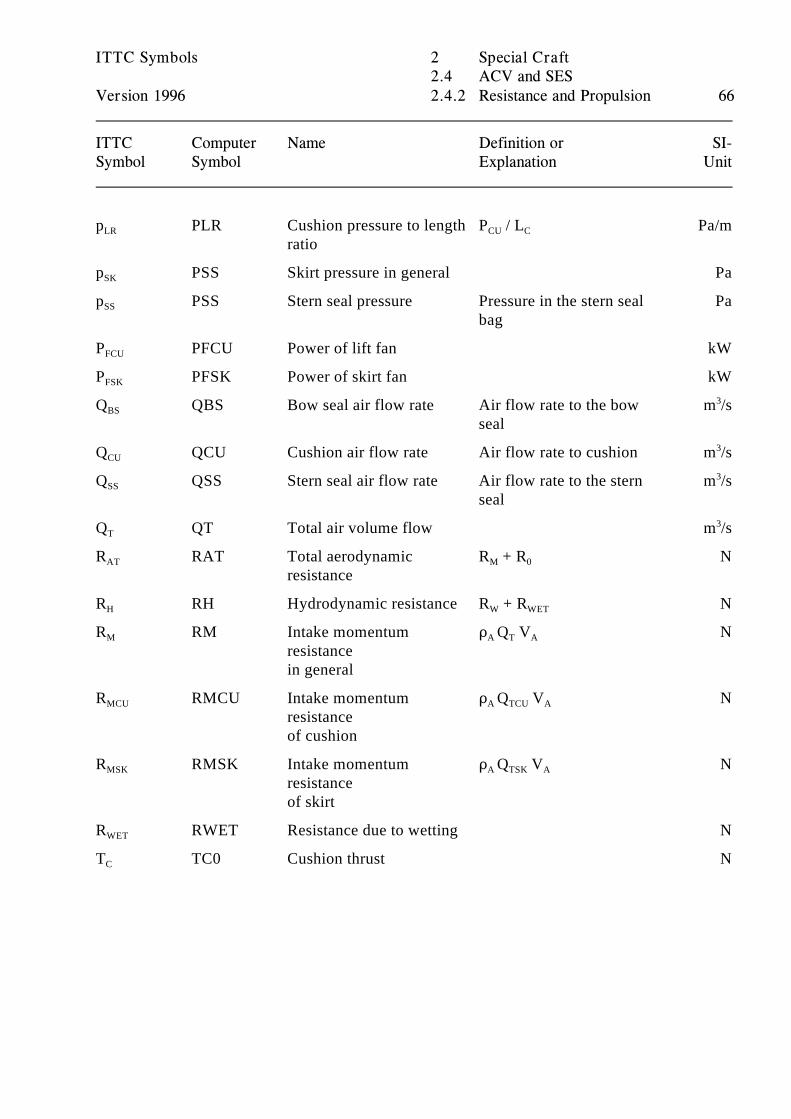
ITTC Symbols 2 Special Craft2.4 ACV and SES
Version 1996 2.4.2 Resistance and Propulsion 66
ITTC Computer Name Definition or SI-Symbol Symbol Explanation Unit
p PLR Cushion pressure to length P / L Pa/mLR
ratioCU C
p PSS Skirt pressure in general PaSK
p PSS Stern seal pressure Pressure in the stern seal PaSS
bag
P PFCU Power of lift fan kWFCU
P PFSK Power of skirt fan kWFSK
Q QBS Bow seal air flow rate Air flow rate to the bow m /sBS
seal
3
Q QCU Cushion air flow rate Air flow rate to cushion m /sCU3
Q QSS Stern seal air flow rate Air flow rate to the stern m /sSS
seal
3
Q QT Total air volume flow m /sT3
R RAT Total aerodynamic R + R NAT
resistanceM 0
R RH Hydrodynamic resistance R + R NH W WET
R RM Intake momentum D Q V NM
resistancein general
A T A
R RMCU Intake momentum D Q V NMCU
resistanceof cushion
A TCU A
R RMSK Intake momentum D Q V NMSK
resistanceof skirt
A TSK A
R RWET Resistance due to wetting NWET
T TC0 Cushion thrust NC
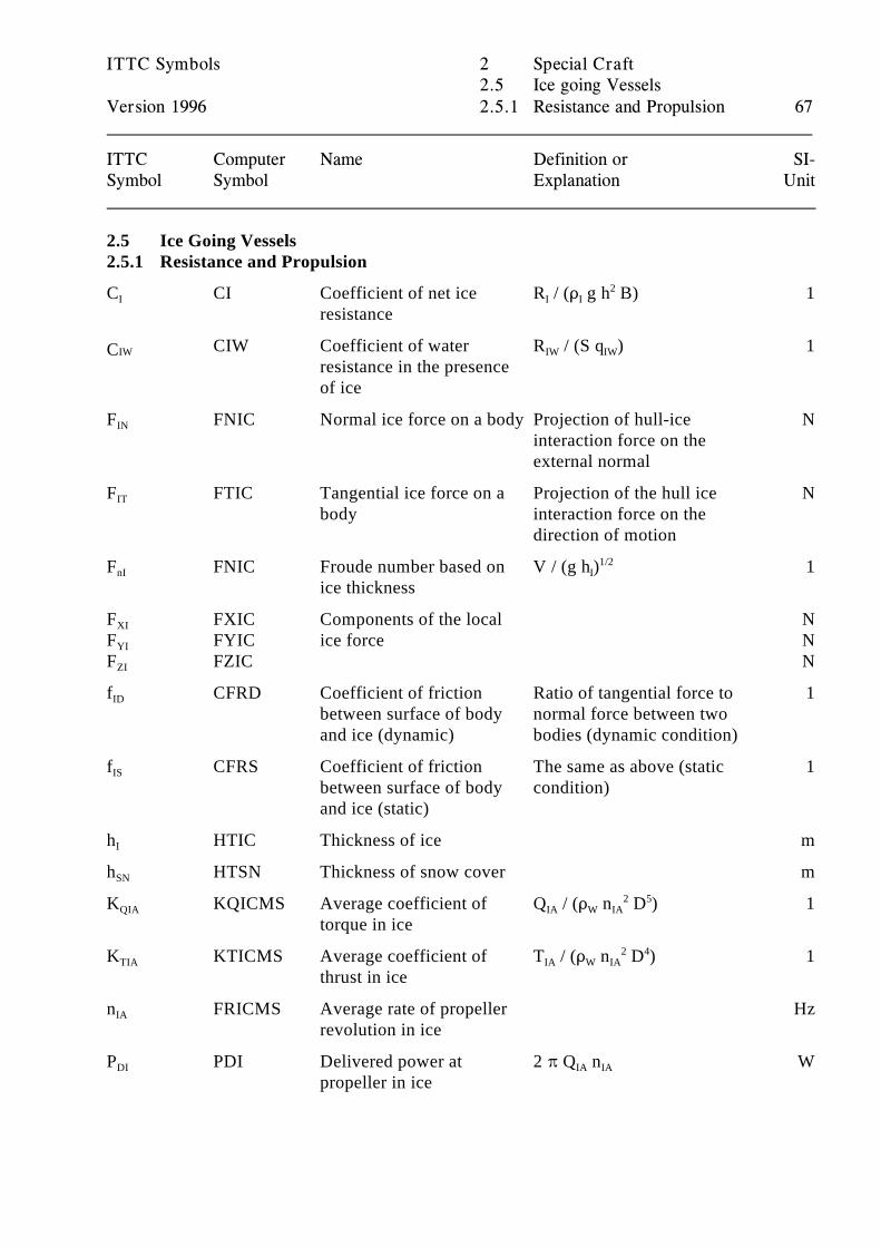
ITTC Symbols 2 Special Craft2.5 Ice going Vessels
Version 1996 2.5.1 Resistance and Propulsion 67
ITTC Computer Name Definition or SI-Symbol Symbol Explanation Unit
2.5 Ice Going Vessels2.5.1 Resistance and Propulsion
C CI Coefficient of net ice R / (D g h B) 1I
resistanceI I
2
CIW Coefficient of water R / (S q ) 1IWCresistance in the presence of ice
IW IW
F FNIC Normal ice force on a body Projection of hull-ice NIN
interaction force on theexternal normal
F FTIC Tangential ice force on a Projection of the hull ice NIT
body interaction force on thedirection of motion
F FNIC Froude number based on V / (g h ) 1nI
ice thicknessI
1/2
F FXIC Components of the local NXI
F FYIC ice force NYI
F FZIC NZI
f CFRD Coefficient of friction Ratio of tangential force to 1ID
between surface of body normal force between twoand ice (dynamic) bodies (dynamic condition)
f CFRS Coefficient of friction The same as above (static 1IS
between surface of body condition)and ice (static)
h HTIC Thickness of ice mI
h HTSN Thickness of snow cover mSN
K KQICMS Average coefficient of Q / (D n D ) 1QIA
torque in iceIA W IA
2 5
K KTICMS Average coefficient of T / (D n D ) 1TIA
thrust in iceIA W IA
2 4
n FRICMS Average rate of propeller HzIA
revolution in ice
P PDI Delivered power at 2 B Q n WDI
propeller in iceIA IA
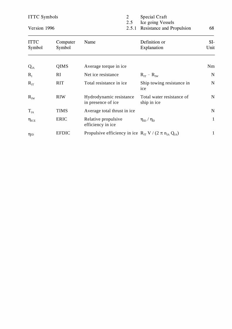
ITTC Symbols 2 Special Craft2.5 Ice going Vessels
Version 1996 2.5.1 Resistance and Propulsion 68
ITTC Computer Name Definition or SI-Symbol Symbol Explanation Unit
Q QIMS Average torque in ice NmIA
R RI Net ice resistance R ! R NI IT IW
R RIT Total resistance in ice Ship towing resistance in NIT
ice
R RIW Hydrodynamic resistance Total water resistance of NIW
in presence of ice ship in ice
T TIMS Average total thrust in ice NIA
0 ERIC Relative propulsive 0 / 0 1ICE
efficiency in iceID D
EFDIC Propulsive efficiency in ice R V / (2 B n Q ) 1ID0 IT IA IA
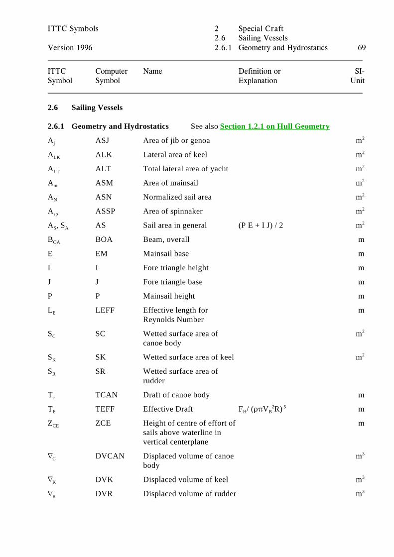
ITTC Symbols 2 Special Craft2.6 Sailing Vessels
Version 1996 2.6.1 Geometry and Hydrostatics 69
ITTC Computer Name Definition or SI-Symbol Symbol Explanation Unit
2.6 Sailing Vessels
2.6.1 Geometry and Hydrostatics See also Section 1.2.1 on Hull Geometry
A ASJ Area of jib or genoa mj2
A ALK Lateral area of keel mLK2
A ALT Total lateral area of yacht mLT2
A ASM Area of mainsail mm2
A ASN Normalized sail area mN2
A ASSP Area of spinnaker msp2
A , S AS Sail area in general (P E + I J) / 2 mS A2
B BOA Beam, overall mOA
E EM Mainsail base m
I I Fore triangle height m
J J Fore triangle base m
P P Mainsail height m
L LEFF Effective length for mE
Reynolds Number
S SC Wetted surface area of mC
canoe body
2
S SK Wetted surface area of keel mK2
S SR Wetted surface area ofR
rudder
T TCAN Draft of canoe body mc
T TEFF Effective Draft F / (DBV R) mE H B2 .5
Z ZCE Height of centre of effort of mCE
sails above waterline invertical centerplane
L DVCAN Displaced volume of canoe mC
body
3
L DVK Displaced volume of keel mK3
L DVR Displaced volume of rudder mR3
ITTC Symbols 2 Special Craft2.6 Sailing Vessels
Version 1996 2.6.2 Resistance and Propulsion 70
ITTC Computer Name Definition or SI-Symbol Symbol Explanation Unit
) DFCAN Displacement force NC
(weight) of canoe body
) DFK Displacement force NK
(weight) of keel
) DFR Displacement force NR
(weight) of rudder
2.6.2 Resistance and Propulsion
C CFU Frictional resistance R / (S q) 1FU
coefficient (upright)FU
C CRU Residuary resistance R / (S q) 1RU
coefficient (upright)RU
C CTU Total resistance R / (S q) 1TU
coefficient (upright)TU
C CWU Wave resistance coefficient 1WU
(upright)
C CTPHI Total resistance coefficient R / (S q) 1TN
with heel and leewayTN
C Induced resistance 1I
coefficient
C , C , C Force coefficients 1x y z
F Heeling force of sails NH
F Driving force of sails NR
F Vertical force of sails NV
H Side force N
L Hydrodynamic lift force NHY
R Added Resistance in waves Naw
R Friction resistance (upright) NFU
R Residuary resistance NRU
(upright)
R Resistance increase due to NI
side (induced resistance)
R RTU Total resistance (upright) NTU
ITTC Symbols 2 Special Craft2.6 Sailing Vessels
Version 1996 2.6.2 Resistance and Propulsion 71
ITTC Computer Name Definition or SI-Symbol Symbol Explanation Unit
R RTUH Total resistance when R + R NTN
heeledTU N
R , R RTUHA Resistance increase due to NN H
heel (with zero side force)
X,Y,Z Components of resultant Nforce along designated axis
U V Boat velocity m/s
U VWREL Apparent wind velocity m/saw
V VWABS True wind velocity m/stw
V VMC Velocity made good on m/smc
course
V VMG Velocity made good to m/smg
windward (contrary towind direction)
$ BETAL lewway angle radl
$ BETWA apparent wind angle radaw
(relative to boat course)
$ BETWT true wind angle (relative to radtw
boat course)
2.6.3 Remarks
This is only a partical list of symbols used in this specialized area. For a more complete list ofsailing yacht symbols and how they are used, see Peter van Oossanen, “Predicting the Speed ofSailing Yachts” Proceedings of Annual Meeting of SNAME, 1993
ITTC Symbols 3 Mechanics in General3.1 Fundamental Concepts
Version 1996 3.1.1 Coordinates and Space related Quantities72
ITTC Computer Name Definition or SI-Symbol Symbol Explanation Unit
3 Mechanics in General3.1 Fundamental Concepts3.1.1 Coordinates and Space Related Quantities3.1.1.1 Coordinate systems
Orientation of coordinates
A problem of general interest, the orientation of the axes of coordinate systems, has been treatedextensively in the Report of the 17th ITTC Information Committee. The present SaT Grouprecommends that the orientations of the coordinate systems chosen for convience should be statedexplicity in any case. The coordinate system orientation should not be inferred from the symbolsand/or names of the concepts or from national or professional traditions. All sign conventions ofrelated Quantities should be consistant with the orientation chosen.
For ready reference the recommendation of the 17th ITTC Information Committee is quoted in thefollowing.
"In order to adapt ITTC nomenclature to common practice a proposal for a standardcoordinate system was published in the newsletter No 7, March 1983, to generate discussion.The response was quite diverse. On the one hand it was suggested that instead of the twoorthogonal right handed systems with the positive x-axis forward and the positive z-axiseither up- or downward as proposed only one system should be selected, in particular theone with the positve z-axis upwards. On the other hand the attention of the InformationCommittee was drawn to the fact that in ship flow calculations neither of the two systemsproposed is customary. Normally the x-axis is directed in the main flow direction, i.e.backwards, the y-axis is taken positive to starboard and the z-axis is positive upwards. Theorigin of the co-ordinates in this case is usually in the undisturbed free surface half waybetween fore and aft perpendicular.
In view of this state of affairs the Information Committee (now SaT Group) may offer thefollowing recommendation, if any:
Axes, coordinates
Preferably, orthogonal right handed systems of Cartesian co-ordinates should be used,orientation and origin in any particular case should be chosen for convenience.
Body axes (x,y,z)
Coordinate systems fixed in bodies or ships.
For the definition of hull forms, for structural deflections, and exciting forces usually the x-axis positive forward and parallel to the reference or base line used to describe the body'sshape, the y-axis positve to port, and the z-axis positive upwards.
ITTC Symbols 3 Mechanics in General3.1 Fundamental Concepts
Version 1996 3.1.1 Coordinates and Space related Quantities73
ITTC Computer Name Definition or SI-Symbol Symbol Explanation Unit
For seakeeping and manoeuvring problems usually the x-axis as before the y-axis positiveto starboard, and the z-axis positive downwards, the origin customarily at the centre of massof the vehicle or at a geometrically defined position.
For ship flow calculations usually the x-axis positive in the main flow direction, i.e.backwards, the y-axis positive to starboard,and the z-axis positive upwards, the origincustomarily at the intersection of the plane of the undisturbed free-surface, the centre plane,and the midship section.
Fixed or space axes (x ,y ,z )0 0 0
Coordinate systems fixed in relation to the earth or the water. For further references see ISOStandard 1151/1 ...6: Terms and symbols for flight dynamics.
The Information Committee is aware that there may be other coordinate systems in use andsees no possibility for the adoption of a single system for all purposes. Any problem requiresan adequate coordinate system and transformations between systems are simple, providedthat orientations and origins are completely and correctly documented for any particularcase."
Origins of coordinates
In seakeeping and manoeuvring problems customarily the centre of mass of the vehicle is chosenas the origin of the coordinates. This is in most cases not necessarily advantageous, as all thehydrodynamic properties entering the problems are related rather to the geometries of the bodiesunder investigation. So any geometrically defined point may be more adequate for the purposes athand.
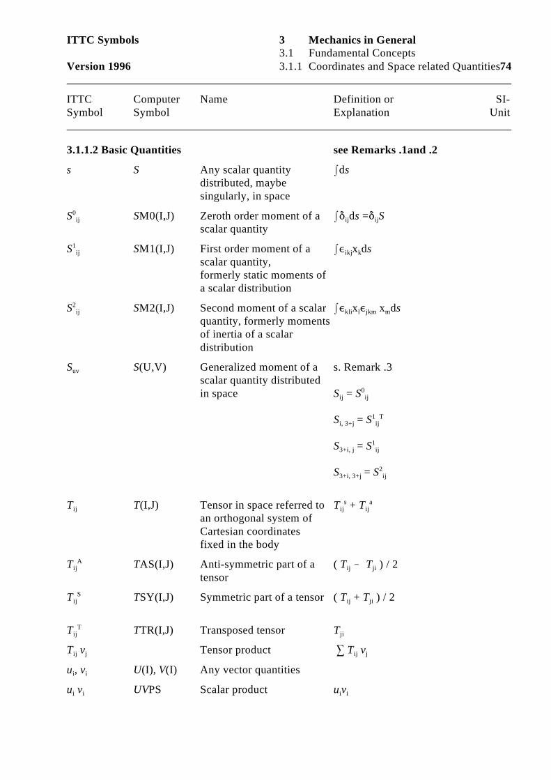
ITTC Symbols 3 Mechanics in General3.1 Fundamental Concepts
Version 1996 3.1.1 Coordinates and Space related Quantities74
ITTC Computer Name Definition or SI-Symbol Symbol Explanation Unit
3.1.1.2 Basic Quantities see Remarks .1and .2
s S Any scalar quantity Idsdistributed, maybesingularly, in space
S SM0(I,J) Zeroth order moment of a I* ds =* S0ij
scalar quantityij ij
S SM1(I,J) First order moment of a I, x ds1ij
scalar quantity,formerly static moments ofa scalar distribution
ikj k
S SM2(I,J) Second moment of a scalar I, x , x ds2ij
quantity, formerly momentsof inertia of a scalardistribution
kli l jkm m
S S(U,V) Generalized moment of a s. Remark .3uv
scalar quantity distributedin space S = S ij ij
0
S = S i, 3+j ij1 T
S = S 3+i, j ij1
S = S 3+i, 3+j ij2
T T(I,J) Tensor in space referred to T + Tij
an orthogonal system ofCartesian coordinatesfixed in the body
ij ijs a
T TAS(I,J) Anti-symmetric part of a ( T ! T ) / 2 ijA
tensorij ji
T TSY(I,J) Symmetric part of a tensor ( T + T ) / 2 ijS
ij ji
T TTR(I,J) Transposed tensor TijT
ji
T v Tensor product 3 T vij j ij j
u , v U(I), V(I) Any vector quantities i i
u v UVPS Scalar product u vi i i i
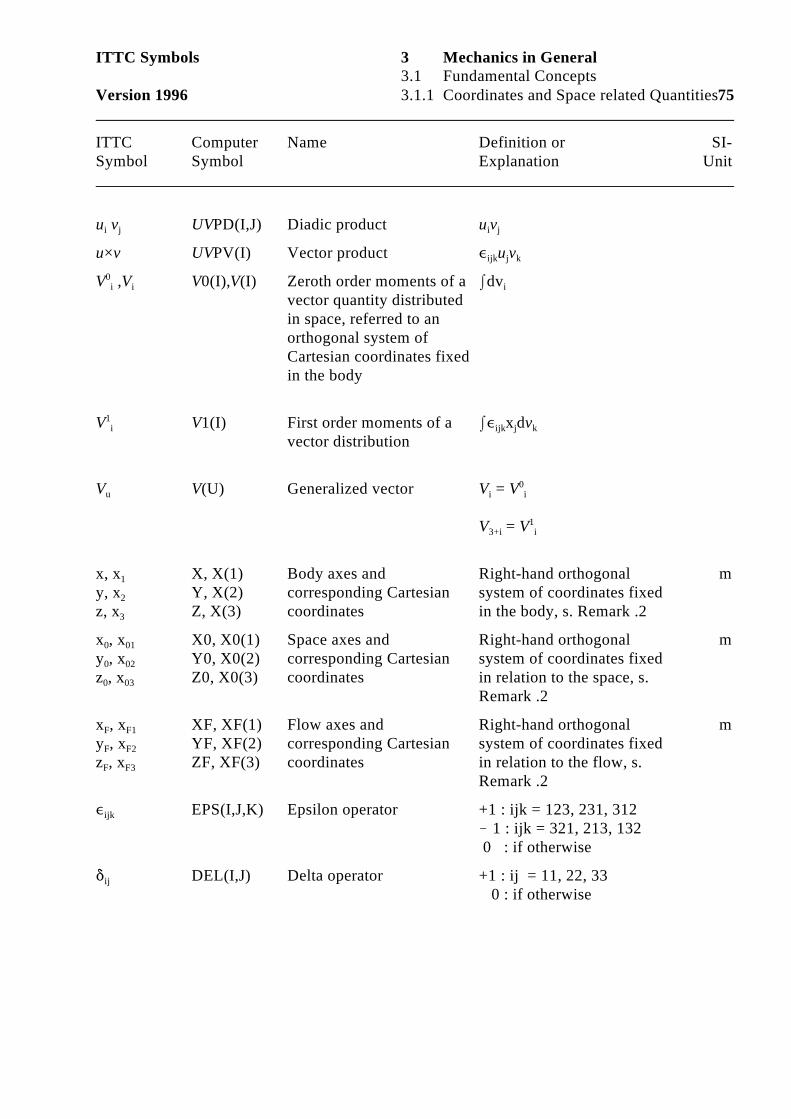
ITTC Symbols 3 Mechanics in General3.1 Fundamental Concepts
Version 1996 3.1.1 Coordinates and Space related Quantities75
ITTC Computer Name Definition or SI-Symbol Symbol Explanation Unit
u v UVPD(I,J) Diadic product u vi j i j
u×v UVPV(I) Vector product , u vijk j k
V ,V V0(I),V(I) Zeroth order moments of a Idv0i i
vector quantity distributedin space, referred to anorthogonal system ofCartesian coordinates fixedin the body
i
V V1(I) First order moments of a I, x dv1i
vector distributionijk j k
V V(U) Generalized vector V = Vu i i0
V = V3+i i1
x, x X, X(1) Body axes and Right-hand orthogonal m1
y, x Y, X(2) corresponding Cartesian system of coordinates fixed2
z, x Z, X(3) coordinates in the body, s. Remark .23
x , x X0, X0(1) Space axes and Right-hand orthogonal m0 01
y , x Y0, X0(2) corresponding Cartesian system of coordinates fixed0 02
z , x Z0, X0(3) coordinates in relation to the space, s.0 03
Remark .2
x , x XF, XF(1) Flow axes and Right-hand orthogonal mF F1
y , x YF, XF(2) corresponding Cartesian system of coordinates fixedF F2
z , x ZF, XF(3) coordinates in relation to the flow, s.F F3
Remark .2
, EPS(I,J,K) Epsilon operator +1 : ijk = 123, 231, 312ijk
! 1 : ijk = 321, 213, 132 0 : if otherwise
* DEL(I,J) Delta operator +1 : ij = 11, 22, 33ij
0 : if otherwise
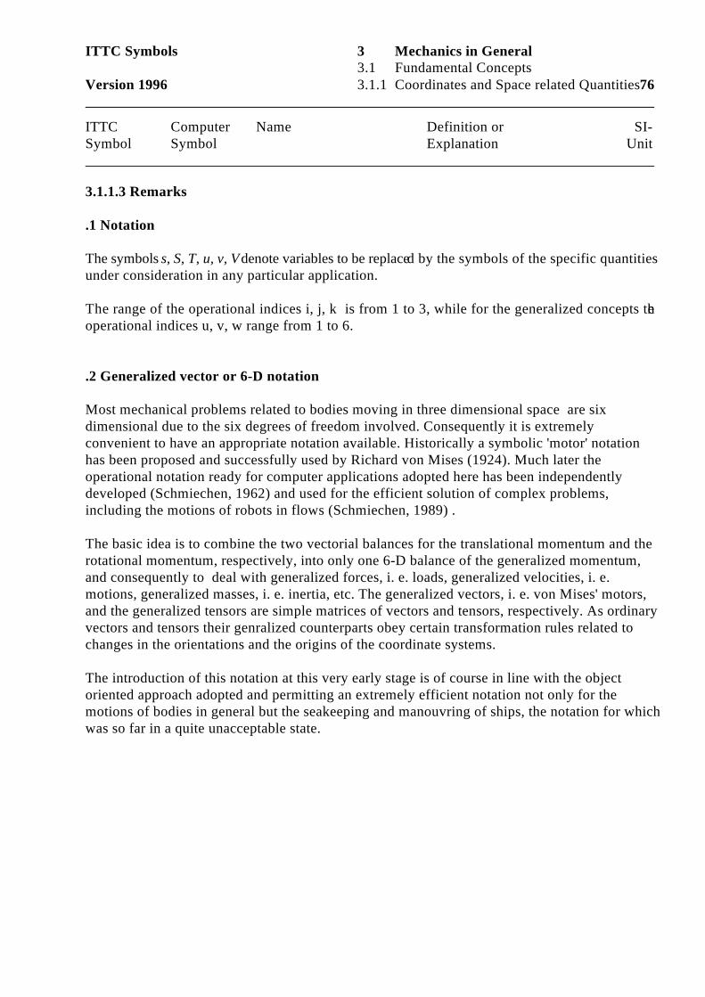
ITTC Symbols 3 Mechanics in General3.1 Fundamental Concepts
Version 1996 3.1.1 Coordinates and Space related Quantities76
ITTC Computer Name Definition or SI-Symbol Symbol Explanation Unit
3.1.1.3 Remarks
.1 Notation
The symbols s, S, T, u, v, V denote variables to be replaced by the symbols of the specific quantitiesunder consideration in any particular application. The range of the operational indices i, j, k is from 1 to 3, while for the generalized concepts theoperational indices u, v, w range from 1 to 6.
.2 Generalized vector or 6-D notation
Most mechanical problems related to bodies moving in three dimensional space are sixdimensional due to the six degrees of freedom involved. Consequently it is extremelyconvenient to have an appropriate notation available. Historically a symbolic 'motor' notationhas been proposed and successfully used by Richard von Mises (1924). Much later theoperational notation ready for computer applications adopted here has been independentlydeveloped (Schmiechen, 1962) and used for the efficient solution of complex problems,including the motions of robots in flows (Schmiechen, 1989) .
The basic idea is to combine the two vectorial balances for the translational momentum and therotational momentum, respectively, into only one 6-D balance of the generalized momentum, and consequently to deal with generalized forces, i. e. loads, generalized velocities, i. e.motions, generalized masses, i. e. inertia, etc. The generalized vectors, i. e. von Mises' motors,and the generalized tensors are simple matrices of vectors and tensors, respectively. As ordinaryvectors and tensors their genralized counterparts obey certain transformation rules related tochanges in the orientations and the origins of the coordinate systems.
The introduction of this notation at this very early stage is of course in line with the objectoriented approach adopted and permitting an extremely efficient notation not only for themotions of bodies in general but the seakeeping and manouvring of ships, the notation for whichwas so far in a quite unacceptable state.
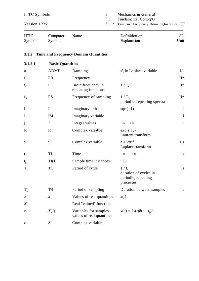
ITTC Symbols 3 Mechanics in General3.1 Fundamental Concepts
Version 1996 3.1.2 Time and Frequency Domain Quantities 77
ITTC Computer Name Definition or SI-Symbol Symbol Explanation Unit
3.1.2 Time and Frequency Domain Quantities
3.1.2.1 Basic Quantities
a ADMP Damping s , in Laplace variable 1/sr
f FR Frequency Hz
f FC Basic frequency in 1 / T HzC
repeating functionsC
f FS Frequency of sampling 1 / T HzS S
period in repeating spectra
i I Imaginary unit sqrt(!1) 1
I IM Imaginary variable i
j J Integer values !4 ...+4 1
R R Complex variable exp(s T )S
Laurent transform
s S Complex variable a + 2Bif 1/sLaplace transform
t TI Time !4 ... +4 s
t TI(J) Sample time instances j Tj S
T TC Period of cycle 1 / f sC C
duration of cycles inperiodic, repeatingprocesses
T TS Period of sampling Duration between samples sS
x x Values of real quantities x(t)
X Real "valued" function
x X(J) Variables for samples x(t ) = Ix(t)*(t ! t )dtj
values of real quantitiesj j
z Z Complex variable
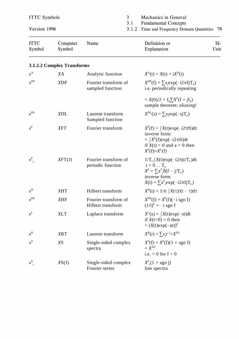
ITTC Symbols 3 Mechanics in General3.1 Fundamental Concepts
Version 1996 3.1.2 Time and Frequency Domain Quantities 78
ITTC Computer Name Definition or SI-Symbol Symbol Explanation Unit
3.1.2.2 Complex Transforms
x XA Analytic function X (t) = X(t) + iX (t)A A H
x XDF Fourier transform of X (f) = 3x exp(!i2BfjT )DF
sampled function
DFj S
i.e. periodically repeating
= X(0)/2 + f 3X (f + jf )S SF
sample theorem: aliasing!
x XDL Laurent transform X (s) = 3x exp(!sjT )DL
Sampled function
DLj S
x XFT Fourier transform X (f) = IX(t)exp(!i2Bft)dtF F
inverse form:= IX (f)exp(!i2Bft)dtF
if X(t) = 0 and a = 0 thenX (f)=X (f) F L
x XFT(J) Fourier transform of 1/T IX(t)exp(!i2Bjt/T )dtFj
periodic function t = 0 . . T C C
C
X = 3x *(f ! j/T )F Fj C
inverse form:X(t) = 3x exp(!i2BfjT )F
j C
x XHT Hilbert transform X (t) = 1/B IX(J)/(t ! J)dJH H
x XHF Fourier transform of X (f) = X (f)(!i sgn f)HF
Hilbert transform (1/t) = !i sgn f
HF F
F
x XLT Laplace transform X (s) = IX(t)exp(!st)dtL L
if X(t<0) = 0 then= (X(t)exp(!at))F
x XRT Laurent transform X (r) =3x r =XR R !j DL j
x XS Single-sided complex X (f) = X (f)(1 + sgn f)S
spectra = X
S F
AF
i.e. = 0 for f < 0
x XS(J) Single-sided complex X (1 + sgn j)Sj
Fourier series line spectra
Fj
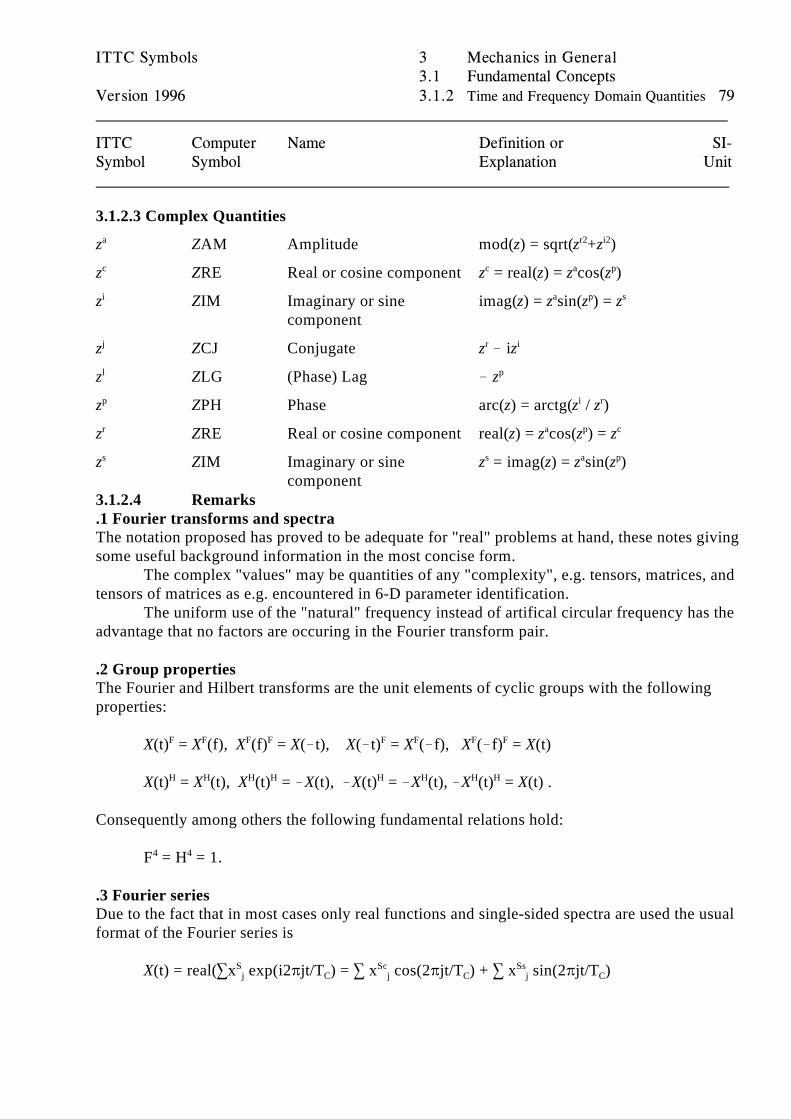
ITTC Symbols 3 Mechanics in General3.1 Fundamental Concepts
Version 1996 3.1.2 Time and Frequency Domain Quantities 79
ITTC Computer Name Definition or SI-Symbol Symbol Explanation Unit
3.1.2.3 Complex Quantities
z ZAM Amplitude mod(z) = sqrt(z +z )a r2 i2
z ZRE Real or cosine component z = real(z) = z cos(z )c c a p
z ZIM Imaginary or sine imag(z) = z sin(z ) = zi
component
a p s
z ZCJ Conjugate z ! izj r i
z ZLG (Phase) Lag ! zl p
z ZPH Phase arc(z) = arctg(z / z )p i r
z ZRE Real or cosine component real(z) = z cos(z ) = zr a p c
z ZIM Imaginary or sine z = imag(z) = z sin(z )s
component
s a p
3.1.2.4 Remarks.1 Fourier transforms and spectraThe notation proposed has proved to be adequate for "real" problems at hand, these notes givingsome useful background information in the most concise form.
The complex "values" may be quantities of any "complexity", e.g. tensors, matrices, andtensors of matrices as e.g. encountered in 6-D parameter identification.
The uniform use of the "natural" frequency instead of artifical circular frequency has theadvantage that no factors are occuring in the Fourier transform pair.
.2 Group propertiesThe Fourier and Hilbert transforms are the unit elements of cyclic groups with the followingproperties:
X(t) = X (f), X (f) = X(!t), X(!t) = X (!f), X (!f) = X(t)F F F F F F F F
X(t) = X (t), X (t) = !X(t), !X(t) = !X (t), !X (t) = X(t) .H H H H H H H H
Consequently among others the following fundamental relations hold:
F = H = 1.4 4
.3 Fourier seriesDue to the fact that in most cases only real functions and single-sided spectra are used the usualformat of the Fourier series is
X(t) = real(3x exp(i2Bjt/T ) = 3 x cos(2Bjt/T ) + 3 x sin(2Bjt/T )S Sc Ssj C j C j C
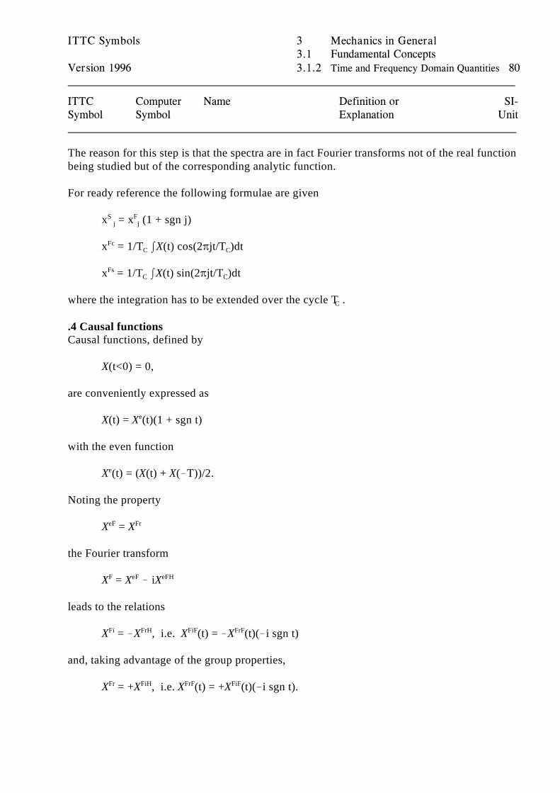
ITTC Symbols 3 Mechanics in General3.1 Fundamental Concepts
Version 1996 3.1.2 Time and Frequency Domain Quantities 80
ITTC Computer Name Definition or SI-Symbol Symbol Explanation Unit
The reason for this step is that the spectra are in fact Fourier transforms not of the real functionbeing studied but of the corresponding analytic function.
For ready reference the following formulae are given
x = x (1 + sgn j)S F j j
x = 1/T IX(t) cos(2Bjt/T )dtFc
C C
x = 1/T IX(t) sin(2Bjt/T )dtFsC C
where the integration has to be extended over the cycle T .C
.4 Causal functionsCausal functions, defined by
X(t<0) = 0,
are conveniently expressed as
X(t) = X (t)(1 + sgn t)e
with the even function
X (t) = (X(t) + X(!T))/2.e
Noting the property
X = XeF Fr
the Fourier transform
X = X ! iXF eF eFH
leads to the relations
X = !X , i.e. X (t) = !X (t)(!i sgn t)Fi FrH FiF FrF
and, taking advantage of the group properties,
X = +X , i.e. X (t) = +X (t)(!i sgn t).Fr FiH FrF FiF
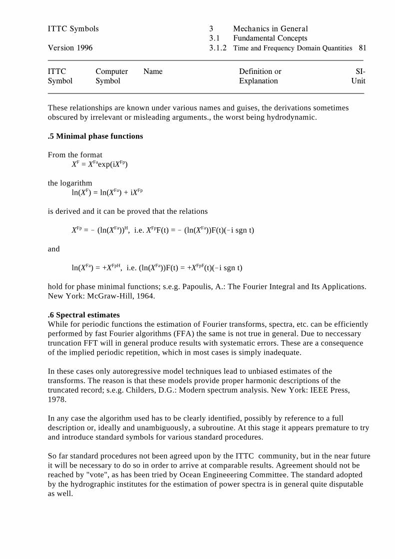
ITTC Symbols 3 Mechanics in General3.1 Fundamental Concepts
Version 1996 3.1.2 Time and Frequency Domain Quantities 81
ITTC Computer Name Definition or SI-Symbol Symbol Explanation Unit
These relationships are known under various names and guises, the derivations sometimesobscured by irrelevant or misleading arguments., the worst being hydrodynamic.
.5 Minimal phase functions
From the formatX = X exp(iX )F Fa Fp
the logarithmln(X ) = ln(X ) + iXF Fa Fp
is derived and it can be proved that the relations
X = ! (ln(X )) , i.e. X F(t) = ! (ln(X ))F(t)(!i sgn t)Fp Fa H Fp Fa
and
ln(X ) = +X , i.e. (ln(X ))F(t) = +X (t)(!i sgn t)Fa FpH Fa FpF
hold for phase minimal functions; s.e.g. Papoulis, A.: The Fourier Integral and Its Applications.New York: McGraw-Hill, 1964.
.6 Spectral estimatesWhile for periodic functions the estimation of Fourier transforms, spectra, etc. can be efficientlyperformed by fast Fourier algorithms (FFA) the same is not true in general. Due to neccessarytruncation FFT will in general produce results with systematic errors. These are a consequenceof the implied periodic repetition, which in most cases is simply inadequate.
In these cases only autoregressive model techniques lead to unbiased estimates of thetransforms. The reason is that these models provide proper harmonic descriptions of thetruncated record; s.e.g. Childers, D.G.: Modern spectrum analysis. New York: IEEE Press,1978.
In any case the algorithm used has to be clearly identified, possibly by reference to a fulldescription or, ideally and unambiguously, a subroutine. At this stage it appears premature to tryand introduce standard symbols for various standard procedures.
So far standard procedures not been agreed upon by the ITTC community, but in the near futureit will be necessary to do so in order to arrive at comparable results. Agreement should not bereached by "vote", as has been tried by Ocean Engineeering Committee. The standard adoptedby the hydrographic institutes for the estimation of power spectra is in general quite disputableas well.
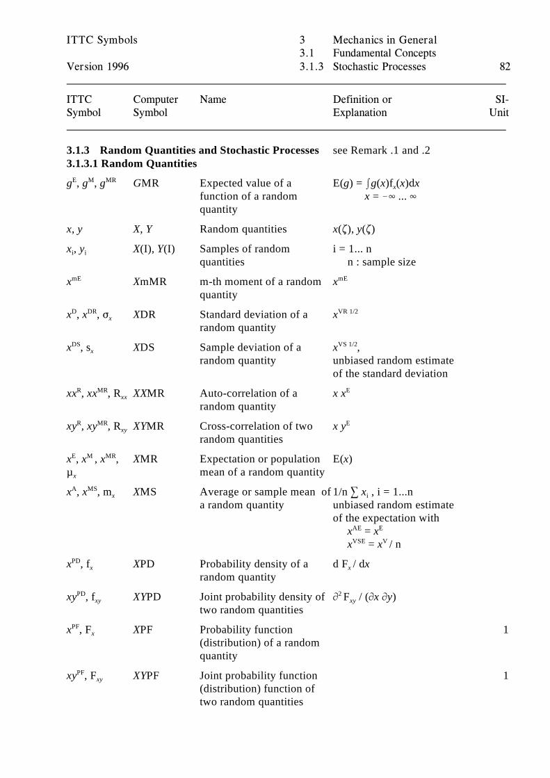
ITTC Symbols 3 Mechanics in General3.1 Fundamental Concepts
Version 1996 3.1.3 Stochastic Processes 82
ITTC Computer Name Definition or SI-Symbol Symbol Explanation Unit
3.1.3 Random Quantities and Stochastic Processes see Remark .1 and .23.1.3.1 Random Quantities
g , g , g GMR Expected value of a E(g) = Ig(x)f (x)dxE M MR
function of a random x = !4 ... 4quantity
x
x, y X, Y Random quantities x(.), y(.)
x , y X(I), Y(I) Samples of random i = 1... n i i
quantities n : sample size
x XmMR m-th moment of a random xmE
quantity
mE
x , x , F XDR Standard deviation of a xD DRx
random quantity
VR 1/2
x , s XDS Sample deviation of a x ,DSx
random quantity unbiased random estimate
VS 1/2
of the standard deviation
xx , xx , R XXMR Auto-correlation of a x xR MRxx
random quantity
E
xy , xy , R XYMR Cross-correlation of two x yR MRxy
random quantities
E
x , x , x , XMR Expectation or population E(x)E M MR
µ mean of a random quantityx
x , x , m XMS Average or sample mean of 1/n 3 x , i = 1...nA MSx
a random quantity unbiased random estimatei
of the expectation with x = xAE E
x = x / nVSE V
x , f XPD Probability density of a d F / dxPDx
random quantityx
xy , f XYPD Joint probability density of M F / (Mx My)PDxy
two random quantities
2 xy
x , F XPF Probability function 1PFx
(distribution) of a randomquantity
xy , F XYPF Joint probability function 1PFxy
(distribution) function oftwo random quantities
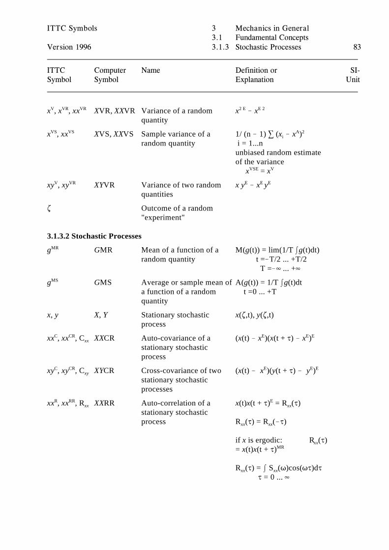
ITTC Symbols 3 Mechanics in General3.1 Fundamental Concepts
Version 1996 3.1.3 Stochastic Processes 83
ITTC Computer Name Definition or SI-Symbol Symbol Explanation Unit
x , x , xx XVR, XXVR Variance of a random x ! xV VR VR
quantity
2 E E 2
x , xx XVS, XXVS Sample variance of a 1/ (n ! 1) 3 (x ! x ) VS VS
random quantity i = 1...ni
A 2
unbiased random estimateof the variance x = xVSE V
xy , xy XYVR Variance of two random x y ! x yV VR
quantities
E E E
. Outcome of a random "experiment"
3.1.3.2 Stochastic Processes
g GMR Mean of a function of a M(g(t)) = lim(1/T Ig(t)dt) MR
random quantity t =!T/2 ... +T/2 T =!4 ... +4
g GMS Average or sample mean of A(g(t)) = 1/T Ig(t)dt MS
a function of a random t =0 ... +Tquantity
x, y X, Y Stationary stochastic x(.,t), y(.,t)process
xx , xx , C XXCR Auto-covariance of a (x(t) ! x )(x(t + J) ! x ) C CRxx
stationary stochasticprocess
E E E
xy , xy , C XYCR Cross-covariance of two (x(t) ! x )(y(t + J) ! y )C CRxy
stationary stochasticprocesses
E E E
xx , xx , R XXRR Auto-correlation of a x(t)x(t + J) = R (J)R RRxx
stationary stochasticprocess R (J) = R (!J)
Exx
xx xx
if x is ergodic: R (J)xx
= x(t)x(t + J)MR
R (J) = I S (T)cos(TJ)dJ xx xx
J = 0 ... 4
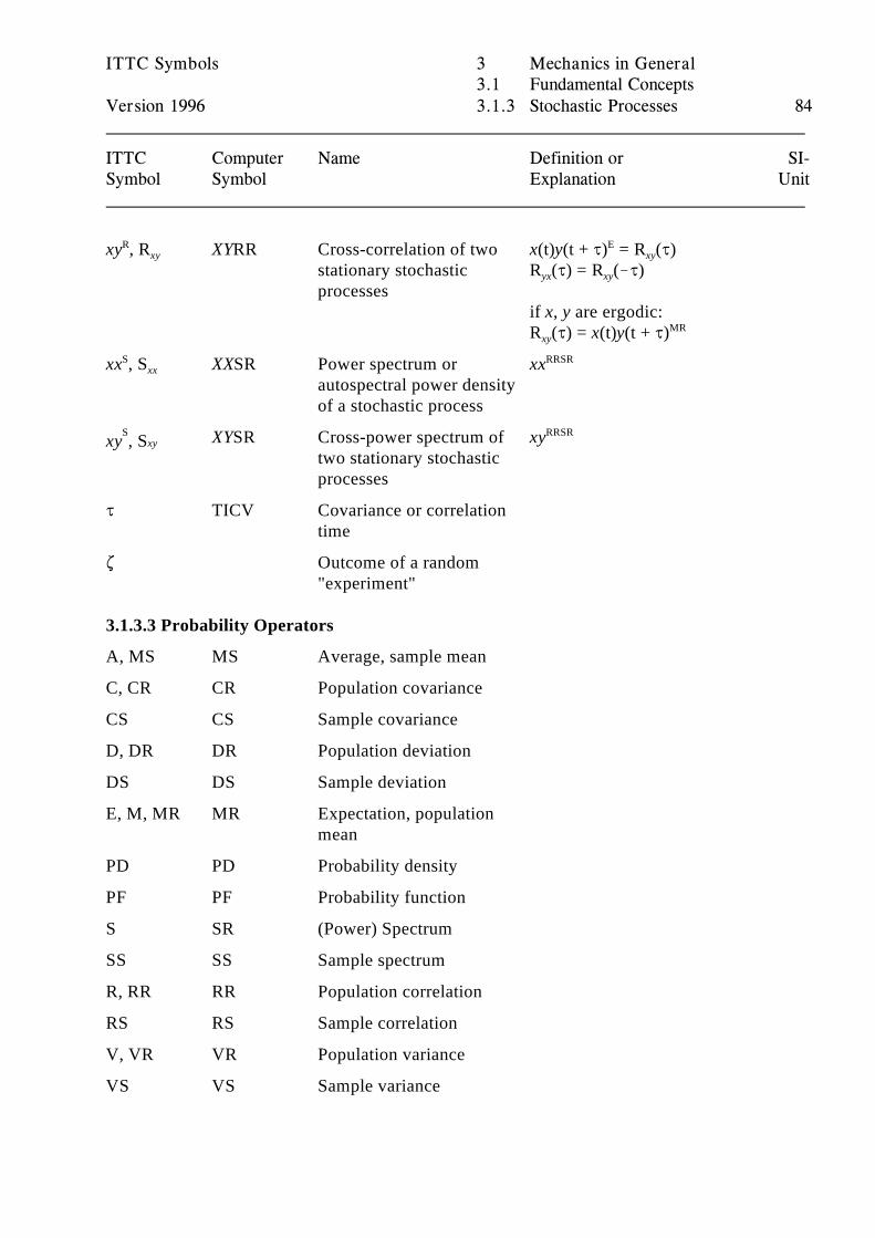
ITTC Symbols 3 Mechanics in General3.1 Fundamental Concepts
Version 1996 3.1.3 Stochastic Processes 84
ITTC Computer Name Definition or SI-Symbol Symbol Explanation Unit
xy , R XYRR Cross-correlation of two x(t)y(t + J) = R (J) Rxy
stationary stochastic R (J) = R (!J)processes
Exy
yx xy
if x, y are ergodic:R (J) = x(t)y(t + J)xy
MR
xx , S XXSR Power spectrum or xxSxx
autospectral power densityof a stochastic process
RRSR
XYSR Cross-power spectrum of xySxyxy , S
two stationary stochastic processes
RRSR
J TICV Covariance or correlationtime
. Outcome of a random "experiment"
3.1.3.3 Probability Operators
A, MS MS Average, sample mean
C, CR CR Population covariance
CS CS Sample covariance
D, DR DR Population deviation
DS DS Sample deviation
E, M, MR MR Expectation, populationmean
PD PD Probability density
PF PF Probability function
S SR (Power) Spectrum
SS SS Sample spectrum
R, RR RR Population correlation
RS RS Sample correlation
V, VR VR Population variance
VS VS Sample variance
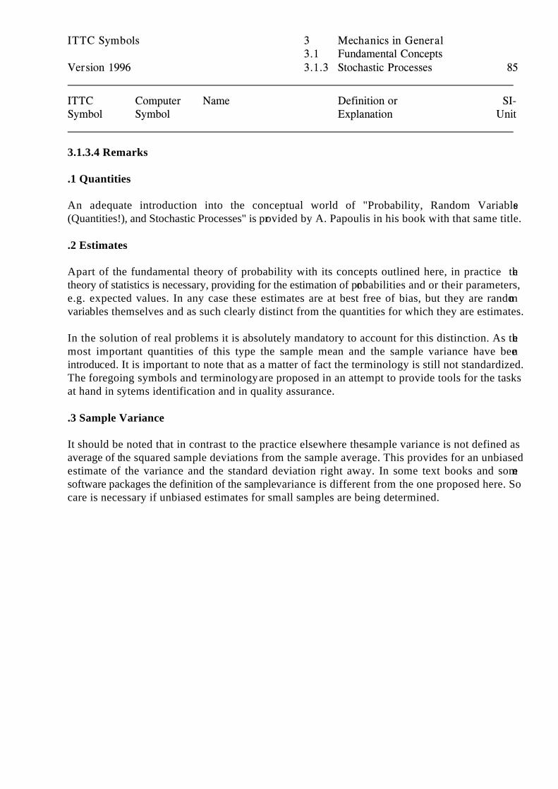
ITTC Symbols 3 Mechanics in General3.1 Fundamental Concepts
Version 1996 3.1.3 Stochastic Processes 85
ITTC Computer Name Definition or SI-Symbol Symbol Explanation Unit
3.1.3.4 Remarks
.1 Quantities
An adequate introduction into the conceptual world of "Probability, Random Variables(Quantities!), and Stochastic Processes" is provided by A. Papoulis in his book with that same title.
.2 Estimates
Apart of the fundamental theory of probability with its concepts outlined here, in practice thetheory of statistics is necessary, providing for the estimation of probabilities and or their parameters,e.g. expected values. In any case these estimates are at best free of bias, but they are randomvariables themselves and as such clearly distinct from the quantities for which they are estimates.
In the solution of real problems it is absolutely mandatory to account for this distinction. As themost important quantities of this type the sample mean and the sample variance have beenintroduced. It is important to note that as a matter of fact the terminology is still not standardized.The foregoing symbols and terminology are proposed in an attempt to provide tools for the tasksat hand in sytems identification and in quality assurance.
.3 Sample Variance
It should be noted that in contrast to the practice elsewhere the sample variance is not defined asaverage of the squared sample deviations from the sample average. This provides for an unbiasedestimate of the variance and the standard deviation right away. In some text books and somesoftware packages the definition of the sample variance is different from the one proposed here. Socare is necessary if unbiased estimates for small samples are being determined.
ITTC Symbols 3 Mechanics in General3.1 Fundamental Concepts
Version 1996 3.1.4 Balances and System Related Concepts 86
ITTC Computer Name Definition or SI-Symbol Symbol Explanation Unit
3.1.4 Balances and System Related Concepts see Remark .1
q QQ Quantity of the quality Qunder consideration storedin a control volume
U
Q Quality under consideration Q /sU
Q QCF Convective flux Q /sC U
Q QDF Diffusive flux Q /sD U
Q QFL Total flux across the Inward positive! Q /sF
surface of the controlvolume
U
Q QDM Molocular diffusion Q /sM U
Q QPN Production of sources in the Q /sP
control volume
U
Q QRT Storage in the control dq / dt Q /sS
volume, rate of change ofthe quantity stored
U
Q QDT Turbulent diffusion Q /sT U
3.1.4.1 Remarks
.1 BalancesTraditionally balances of various extensive or socalled "conservative" qualities or properties aredescribed by ad hoc symbols, disguising the similarities and essentials. For any quality Q enclosedin a control volume the balance may be written in the format
Q = Q + Q ,S F P
implying, that the net storage of the quality in a given boundary equals the net flux of the qualityacross the boundary into the control volume and the net production of sources within the boundary.
The symbol Q is the variable for the symbol of the particular extensive qualitiy under investigation,e. g. mass, momentum, and energy. Q , Q , and Q are variables for values of the storage, flux, andS F P
production, respectively.
q
ITTC Symbols 3 Mechanics in General3.1 Fundamental Concepts
Version 1996 3.1.4 Balances and System Related Concepts 87
ITTC Computer Name Definition or SI-Symbol Symbol Explanation Unit
The net storage is nothing else but the net rate of change of the quantity q of the quality Q stored inthe control volume:
Q = dq / dt .S
q is the variable for values of the quantity of the quality Q stored in the control volume.
Concerning the flux there are two types to be clearly distinguished according to their mechanisms,the convective and the diffusive fluxes, i. e.
Q = Q + Q . F C D
The diffusive flux itself may be due to two types of diffusion, the molecular diffusion and theturbulent diffusion, i. e.
Q = Q + Q .D T M
Traditionally the time rate of change is denoted by a dot, i. e.
dq / dt =
According to some standards, e. g. the German DIN, fluxes and the productions may be denoted bysymbols with a dot as well, apparently due to the fact, that they have the same dimension as time ratesof change. This usage is misleading and confusing and therefore totally unacceptable.
The concepts of flux and source are fundamental concepts and essentially different, due to the totallydifferent nature of the mechanisms, from the concept of rate of change of the quantity they cause tochange, although they may each, in the absence of the other, be equal in value and balancing the rateof change.
Much more reasonable is to denote rate of change by an operator symbol as well, e. g. by R, as willbe done in this version of the symbols, and write any balance in the format
q = Q = Q + Q + Q + Q ,R S C T M P
clearly indicating the four totally different physical mechanisms taking part in the change of anyquantities of extensive qualities.
If instead of the object oriented notation the function oriented notation is being used the balancewould e. g. look like
q = S = C + T + M + P .RQ Q Q Q Q
ITTC Symbols 3 Mechanics in General3.1 Fundamental Concepts
Version 1996 3.1.4 Balances and System Related Concepts 88
ITTC Computer Name Definition or SI-Symbol Symbol Explanation Unit
This is not very practical if the quality under consideration is of tensorial character or of even morecomplex matrix nature. Q is the variable for the SI unit of the quality Q under consideration.U
It will become evident from this very elementary exposition that precisely the most fundamentalconcepts are mostly used extremely carelessly. The concepts "variable", "quantity", and "quality" arerarely clearly distinguished as they ought to be.
E. g.: momentum is a quality and a body may have stored a certain quantity of it at a given time. Mand MO are variables for vectors of numerical values of the quantity measured in Ns. t and TI arevariables for values of the quantity of the quality time measured in s .
V
ITTC Symbols 3 Mechanics in General3.2 Solid Body Mechanics
Version 1996 3.2.1 Inertial and Hydro Properties 89
ITTC Computer Name Definition or SI-Symbol Symbol Explanation Unit
3.2 Solid Body Mechanics3.2.1 Inertial and Hydrodynamic Properties3.2.1.1 Basic Quantities see Remarks
A AM(I,J) Added mass coefficient inij
ith mode due to jth motion
B DA(I,J) Damping coefficient in ithij
mode due to jth motion
C RF(I,J) Restoring force coefficientij
in ith mode due to jthmotion
D DH(U,V) Generalized hydrodynamic MF / MV huv
damping
hu v
F FH(U) Generalized hydrodynamic hu
force
I IH(U,V) Generalized hydrodynamichuv
inertiaMF / Mh
u v
I IL Longitudinal second About transverse axis mL
moment of water-plane area through center of floatation
4
I IT Transverse second moment About longitudinal axis mT
of water-plane area through center of floatation
4
I , I , IY, IYY, Pitch moment of inertia kg my yy
m , M2(2,2), around the principal axis y222
m MA(5,5)55
2
I , I , IZ, IZZ, Yaw moment of inertia kg mz zz
m , M2(3,3), around the principal axis z233
m MA(6,6)66
2
I , I IXY, I2(1,2) Real products of inertia in kg mxy 12
I , I IYZ, I2(2,3) case of non-principal axesyz 23
I , I IZX, I2(3,1)zx 31
2
k , k RDGX Roll radius of gyration (I /m) mx xx
k around the principal axis xxx
1/2
k , k RDGY Pitch radius of gyration (I /m) my yy
around the principal axis yyy
1/2
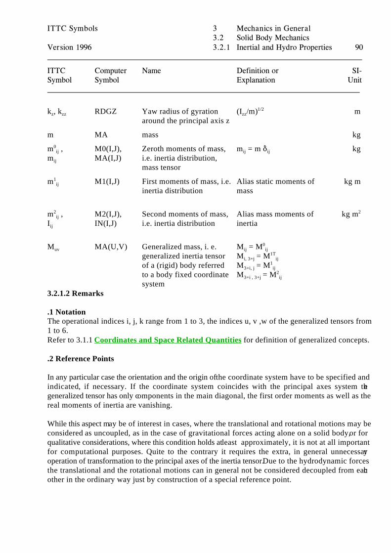
ITTC Symbols 3 Mechanics in General3.2 Solid Body Mechanics
Version 1996 3.2.1 Inertial and Hydro Properties 90
ITTC Computer Name Definition or SI-Symbol Symbol Explanation Unit
k , k RDGZ Yaw radius of gyration (I /m) mz zz
around the principal axis zzz
1/2
m MA mass kg
m , M0(I,J), Zeroth moments of mass, m = m * kg0ij
m MA(I,J) i.e. inertia distribution,ij
mass tensor
ij ij
m M1(I,J) First moments of mass, i.e. Alias static moments of kg m1ij
inertia distribution mass
m , M2(I,J), Second moments of mass, Alias mass moments of kg m2ij
I IN(I,J) i.e. inertia distribution inertiaij
2
M MA(U,V) Generalized mass, i. e. M = Muv
generalized inertia tensor M = Mof a (rigid) body referred M = Mto a body fixed coordinate M = Msystem
ij ij0
i, 3+j ij1T
3+i, j ij1
3+i , 3+j ij2
3.2.1.2 Remarks
.1 NotationThe operational indices i, j, k range from 1 to 3, the indices u, v ,w of the generalized tensors from1 to 6.Refer to 3.1.1 Coordinates and Space Related Quantities for definition of generalized concepts.
.2 Reference Points
In any particular case the orientation and the origin of the coordinate system have to be specified andindicated, if necessary. If the coordinate system coincides with the principal axes system thegeneralized tensor has only components in the main diagonal, the first order moments as well as thereal moments of inertia are vanishing.
While this aspect may be of interest in cases, where the translational and rotational motions may beconsidered as uncoupled, as in the case of gravitational forces acting alone on a solid body, or forqualitative considerations, where this condition holds at least approximately, it is not at all importantfor computational purposes. Quite to the contrary it requires the extra, in general unnecessaryoperation of transformation to the principal axes of the inertia tensor. Due to the hydrodynamic forcesthe translational and the rotational motions can in general not be considered decoupled from eachother in the ordinary way just by construction of a special reference point.
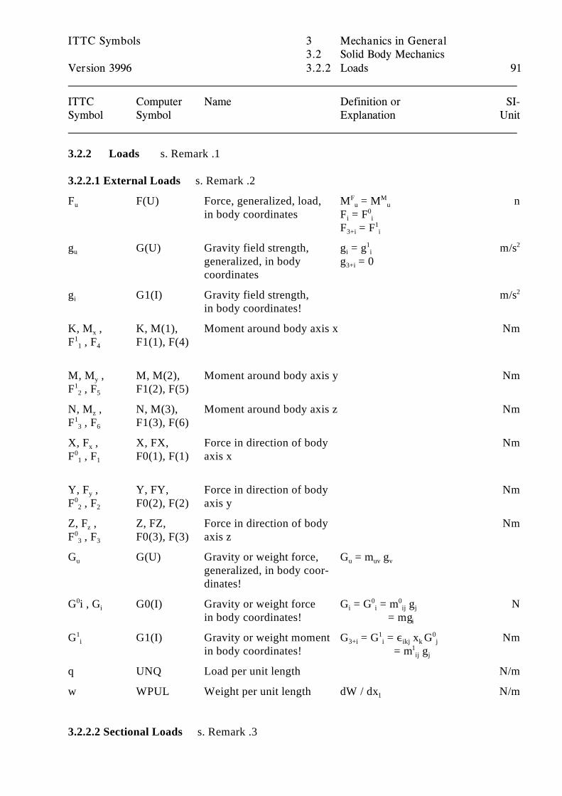
ITTC Symbols 3 Mechanics in General3.2 Solid Body Mechanics
Version 3996 3.2.2 Loads 91
ITTC Computer Name Definition or SI-Symbol Symbol Explanation Unit
3.2.2 Loads s. Remark .1
3.2.2.1 External Loads s. Remark .2
F F(U) Force, generalized, load, M = M nu
in body coordinates F = F
F Mu u
i i0
F = F3+i i1
g G(U) Gravity field strength, g = g m/su
generalized, in body g = 0coordinates
i i1
3+i
2
g G1(I) Gravity field strength, m/si
in body coordinates!
2
K, M , K, M(1), Moment around body axis x Nmx
F , F F1(1), F(4)11 4
M, M , M, M(2), Moment around body axis y Nmy
F , F F1(2), F(5)12 5
N, M , N, M(3), Moment around body axis z Nmz
F , F F1(3), F(6)13 6
X, F , X, FX, Force in direction of body Nmx
F , F F0(1), F(1) axis x01 1
Y, F , Y, FY, Force in direction of body Nmy
F , F F0(2), F(2) axis y02 2
Z, F , Z, FZ, Force in direction of body Nmz
F , F F0(3), F(3) axis z03 3
G G(U) Gravity or weight force, G = m gu
generalized, in body coor-dinates!
u uv v
G i , G G0(I) Gravity or weight force G = G = m g N0i
in body coordinates! = mgi i ij j
0 0
i
G G1(I) Gravity or weight moment G = G = , x G Nm1i
in body coordinates! = m g3+i i ikj k j
1 0
1ij j
q UNQ Load per unit length N/m
w WPUL Weight per unit length dW / dx N/m1
3.2.2.2 Sectional Loads s. Remark .3
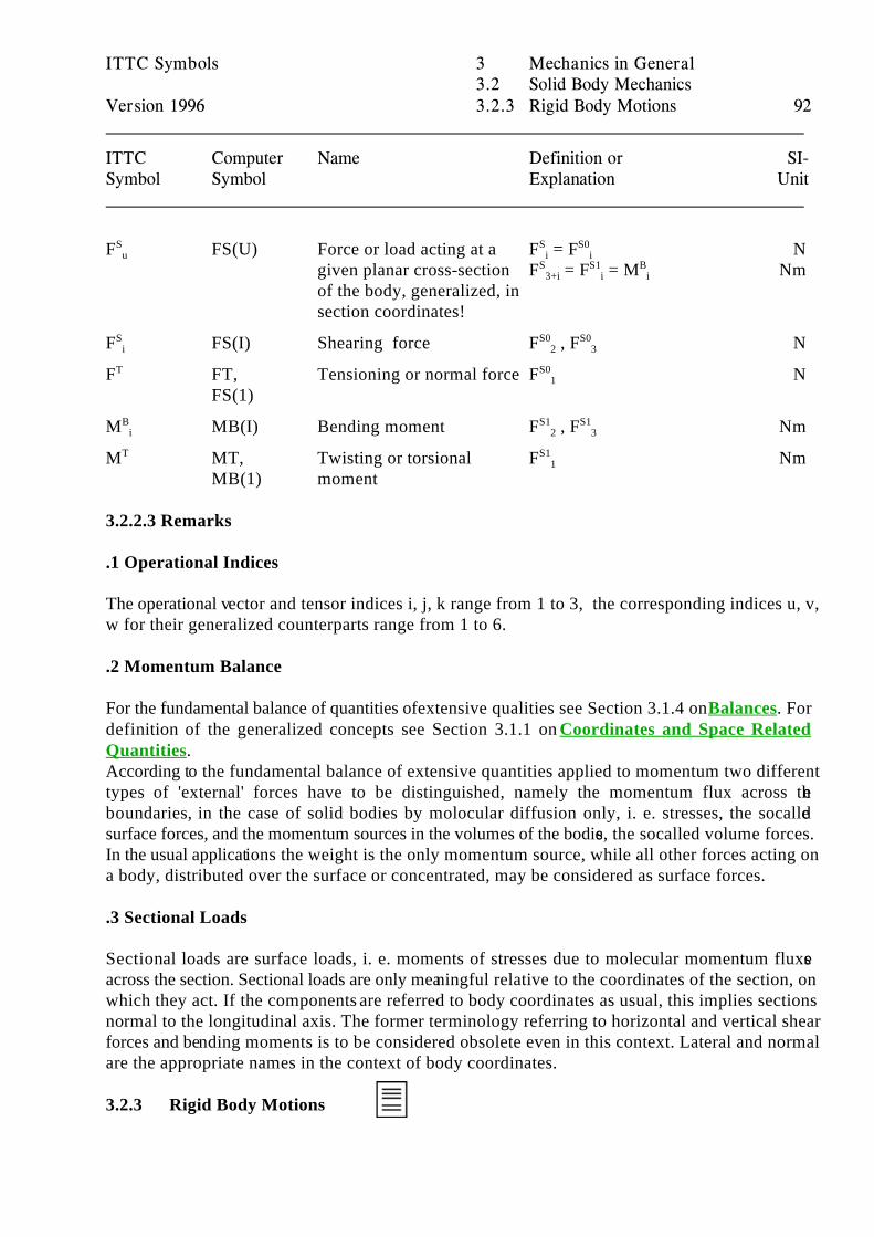
ITTC Symbols 3 Mechanics in General3.2 Solid Body Mechanics
Version 1996 3.2.3 Rigid Body Motions 92
ITTC Computer Name Definition or SI-Symbol Symbol Explanation Unit
F FS(U) Force or load acting at a F = F NSu
given planar cross-section F = F = M Nmof the body, generalized, insection coordinates!
S S0i i
S S1 B3+i i i
F FS(I) Shearing force F , F NSi
S0 S02 3
F FT, Tensioning or normal force F NT
FS(1)
S01
M MB(I) Bending moment F , F NmBi
S1 S12 3
M MT, Twisting or torsional F NmT
MB(1) moment
S11
3.2.2.3 Remarks
.1 Operational Indices
The operational vector and tensor indices i, j, k range from 1 to 3, the corresponding indices u, v,w for their generalized counterparts range from 1 to 6.
.2 Momentum Balance
For the fundamental balance of quantities of extensive qualities see Section 3.1.4 on Balances. Fordefinition of the generalized concepts see Section 3.1.1 on Coordinates and Space RelatedQuantities.According to the fundamental balance of extensive quantities applied to momentum two differenttypes of 'external' forces have to be distinguished, namely the momentum flux across theboundaries, in the case of solid bodies by molocular diffusion only, i. e. stresses, the socalledsurface forces, and the momentum sources in the volumes of the bodies, the socalled volume forces.In the usual applications the weight is the only momentum source, while all other forces acting ona body, distributed over the surface or concentrated, may be considered as surface forces.
.3 Sectional Loads
Sectional loads are surface loads, i. e. moments of stresses due to molecular momentum fluxesacross the section. Sectional loads are only meaningful relative to the coordinates of the section, onwhich they act. If the components are referred to body coordinates as usual, this implies sectionsnormal to the longitudinal axis. The former terminology referring to horizontal and vertical shearforces and bending moments is to be considered obsolete even in this context. Lateral and normalare the appropriate names in the context of body coordinates.
3.2.3 Rigid Body Motions
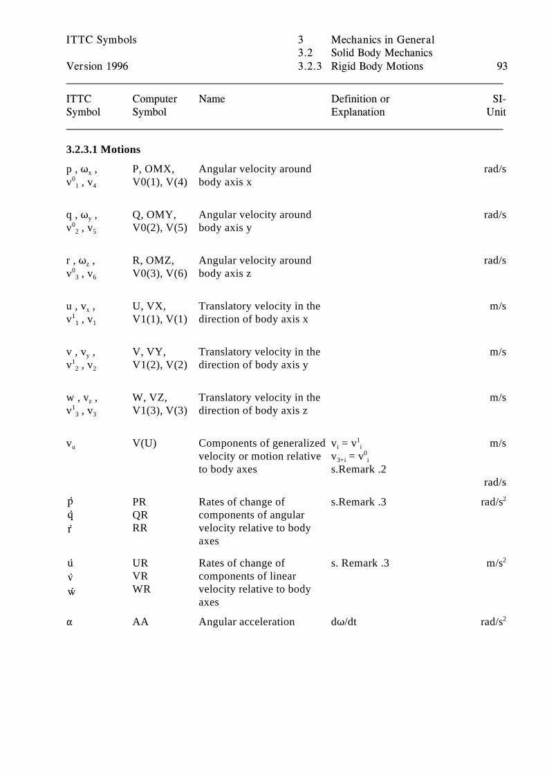
pqr
uvw
ITTC Symbols 3 Mechanics in General3.2 Solid Body Mechanics
Version 1996 3.2.3 Rigid Body Motions 93
ITTC Computer Name Definition or SI-Symbol Symbol Explanation Unit
3.2.3.1 Motions
p , T , P, OMX, Angular velocity around rad/sx
v , v V0(1), V(4) body axis x01 4
q , T , Q, OMY, Angular velocity around rad/sy
v , v V0(2), V(5) body axis y02 5
r , T , R, OMZ, Angular velocity around rad/sz
v , v V0(3), V(6) body axis z03 6
u , v , U, VX, Translatory velocity in the m/sx
v , v V1(1), V(1) direction of body axis x11 1
v , v , V, VY, Translatory velocity in the m/sy
v , v V1(2), V(2) direction of body axis y12 2
w , v , W, VZ, Translatory velocity in the m/sz
v , v V1(3), V(3) direction of body axis z13 3
v V(U) Components of generalized v = v m/su
velocity or motion relative v = vto body axes s.Remark .2
i i1
3+i i0
rad/s
PR Rates of change of s.Remark .3 rad/sQR components of angularRR velocity relative to body
axes
2
UR Rates of change of s. Remark .3 m/sVR components of linearWR velocity relative to body
axes
2
" AA Angular acceleration dT/dt rad/s2
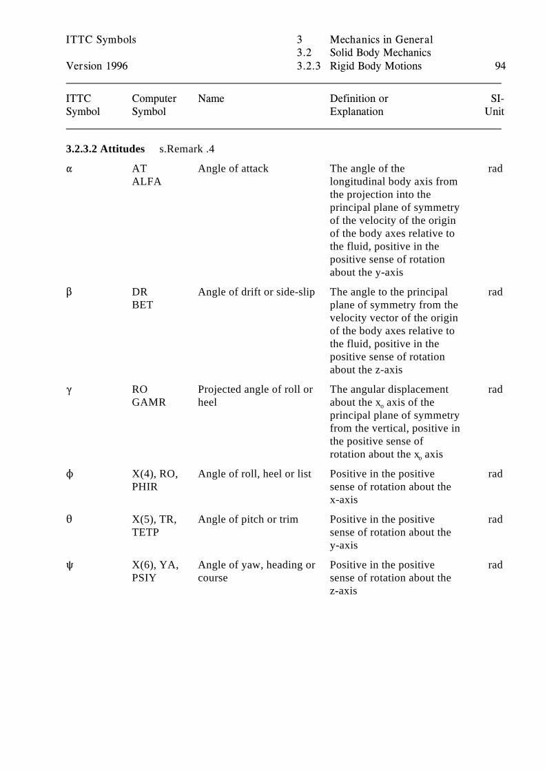
ITTC Symbols 3 Mechanics in General3.2 Solid Body Mechanics
Version 1996 3.2.3 Rigid Body Motions 94
ITTC Computer Name Definition or SI-Symbol Symbol Explanation Unit
3.2.3.2 Attitudes s.Remark .4
" AT Angle of attack The angle of the radALFA longitudinal body axis from
the projection into theprincipal plane of symmetryof the velocity of the originof the body axes relative tothe fluid, positive in thepositive sense of rotationabout the y-axis
$ DR Angle of drift or side-slip The angle to the principal radBET plane of symmetry from the
velocity vector of the originof the body axes relative tothe fluid, positive in thepositive sense of rotationabout the z-axis
( RO Projected angle of roll or The angular displacement radGAMR heel about the x axis of theo
principal plane of symmetryfrom the vertical, positive inthe positive sense ofrotation about the x axiso
N X(4), RO, Angle of roll, heel or list Positive in the positive radPHIR sense of rotation about the
x-axis
2 X(5), TR, Angle of pitch or trim Positive in the positive radTETP sense of rotation about the
y-axis
R X(6), YA, Angle of yaw, heading or Positive in the positive radPSIY course sense of rotation about the
z-axis
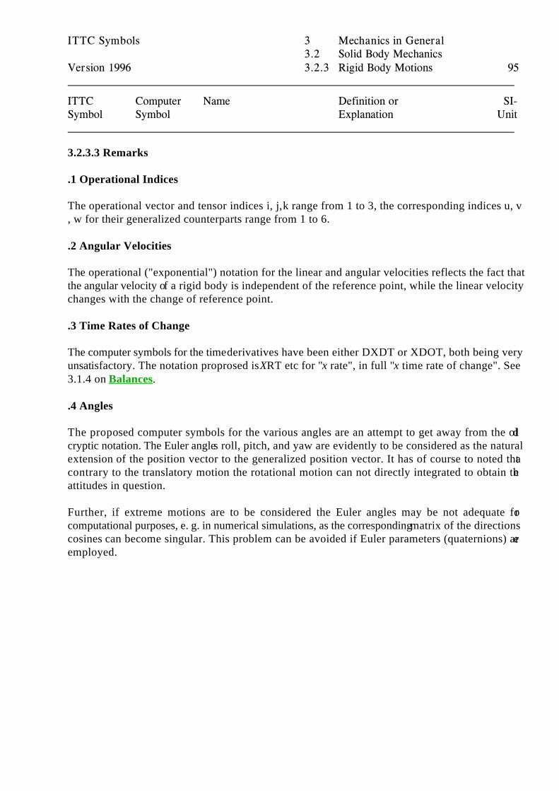
ITTC Symbols 3 Mechanics in General3.2 Solid Body Mechanics
Version 1996 3.2.3 Rigid Body Motions 95
ITTC Computer Name Definition or SI-Symbol Symbol Explanation Unit
3.2.3.3 Remarks
.1 Operational Indices
The operational vector and tensor indices i, j, k range from 1 to 3, the corresponding indices u, v, w for their generalized counterparts range from 1 to 6.
.2 Angular Velocities
The operational ("exponential") notation for the linear and angular velocities reflects the fact thatthe angular velocity of a rigid body is independent of the reference point, while the linear velocitychanges with the change of reference point.
.3 Time Rates of Change
The computer symbols for the time derivatives have been either DXDT or XDOT, both being veryunsatisfactory. The notation proprosed is XRT etc for "x rate", in full "x time rate of change". See3.1.4 on Balances.
.4 Angles
The proposed computer symbols for the various angles are an attempt to get away from the oldcryptic notation. The Euler angles roll, pitch, and yaw are evidently to be considered as the naturalextension of the position vector to the generalized position vector. It has of course to noted thatcontrary to the translatory motion the rotational motion can not directly integrated to obtain theattitudes in question.
Further, if extreme motions are to be considered the Euler angles may be not adequate forcomputational purposes, e. g. in numerical simulations, as the corresponding matrix of the directionscosines can become singular. This problem can be avoided if Euler parameters (quaternions) areemployed.
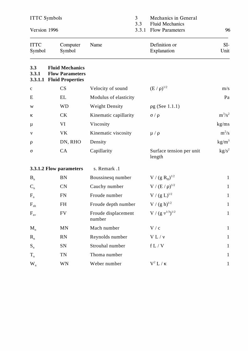
ITTC Symbols 3 Mechanics in General3.3 Fluid Mechanics
Version 1996 3.3.1 Flow Parameters 96
ITTC Computer Name Definition or SI-Symbol Symbol Explanation Unit
3.3 Fluid Mechanics3.3.1 Flow Parameters3.3.1.1 Fluid Properties
c CS Velocity of sound (E / D) m/s1/2
E EL Modulus of elasticity Pa
w WD Weight Density Dg (See 1.1.1)
6 CK Kinematic capillarity F / D m /s3 2
µ VI Viscosity kg/ms
< VK Kinematic viscosity µ / D m /s2
D DN, RHO Density kg/m3
F CA Capillarity Surface tension per unit kg/slength
2
3.3.1.2 Flow parameters s. Remark .1
B BN Boussinesq number V / (g R ) 1n H1/2
C CN Cauchy number V / (E / D) 1n1/2
F FN Froude number V / (g L) 1n1/2
F FH Froude depth number V / (g h) 1nh1/2
F FV Froude displacement V / (g « ) 1n«
number
1/3 1/2
M MN Mach number V / c 1n
R RN Reynolds number V L / < 1n
S SN Strouhal number f L / V 1n
T TN Thoma number 1n
W WN Weber number V L / 6 1n2
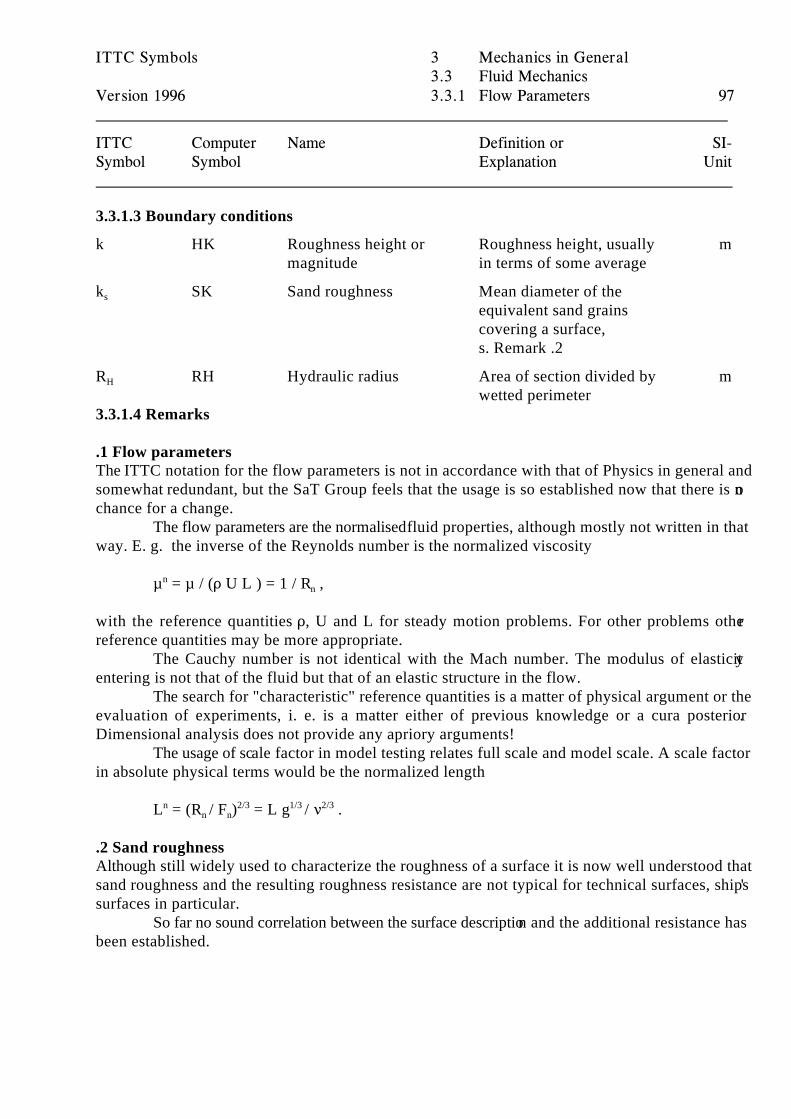
ITTC Symbols 3 Mechanics in General3.3 Fluid Mechanics
Version 1996 3.3.1 Flow Parameters 97
ITTC Computer Name Definition or SI-Symbol Symbol Explanation Unit
3.3.1.3 Boundary conditions
k HK Roughness height or Roughness height, usually mmagnitude in terms of some average
k SK Sand roughness Mean diameter of thes
equivalent sand grainscovering a surface,s. Remark .2
R RH Hydraulic radius Area of section divided by mH
wetted perimeter3.3.1.4 Remarks
.1 Flow parametersThe ITTC notation for the flow parameters is not in accordance with that of Physics in general andsomewhat redundant, but the SaT Group feels that the usage is so established now that there is nochance for a change.
The flow parameters are the normalised fluid properties, although mostly not written in thatway. E. g. the inverse of the Reynolds number is the normalized viscosity
µ = µ / (D U L ) = 1 / R ,nn
with the reference quantities D, U and L for steady motion problems. For other problems otherreference quantities may be more appropriate.
The Cauchy number is not identical with the Mach number. The modulus of elasticityentering is not that of the fluid but that of an elastic structure in the flow.
The search for "characteristic" reference quantities is a matter of physical argument or theevaluation of experiments, i. e. is a matter either of previous knowledge or a cura posterior.Dimensional analysis does not provide any apriory arguments!
The usage of scale factor in model testing relates full scale and model scale. A scale factorin absolute physical terms would be the normalized length
L = (R / F ) = L g / < .n 2/3 1/3 2/3n n
.2 Sand roughnessAlthough still widely used to characterize the roughness of a surface it is now well understood thatsand roughness and the resulting roughness resistance are not typical for technical surfaces, ships'surfaces in particular.
So far no sound correlation between the surface description and the additional resistance hasbeen established.
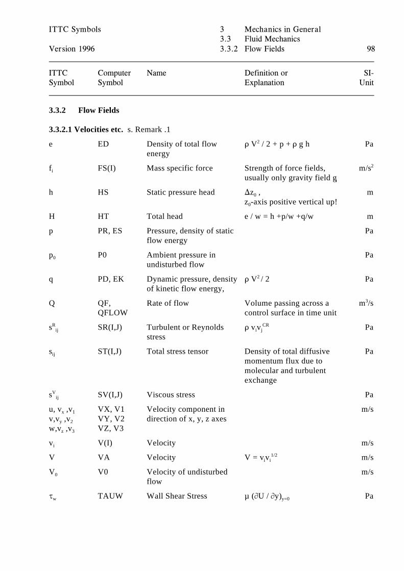
ITTC Symbols 3 Mechanics in General3.3 Fluid Mechanics
Version 1996 3.3.2 Flow Fields 98
ITTC Computer Name Definition or SI-Symbol Symbol Explanation Unit
3.3.2 Flow Fields
3.3.2.1 Velocities etc. s. Remark .1
e ED Density of total flow D V / 2 + p + D g h Paenergy
2
f FS(I) Mass specific force Strength of force fields, m/si
usually only gravity field gi
2
h HS Static pressure head )z , m0
z -axis positive vertical up! 0
H HT Total head e / w = h +p/w +q/w m
p PR, ES Pressure, density of static Paflow energy
p P0 Ambient pressure in Pa0
undisturbed flow
q PD, EK Dynamic pressure, density D V / 2 Paof kinetic flow energy,
2
Q QF, Rate of flow Volume passing across a m /sQFLOW control surface in time unit
3
s SR(I,J) Turbulent or Reynolds D v v PaRij
stressi j
CR
s ST(I,J) Total stress tensor Density of total diffusive Paij
momentum flux due tomolecular and turbulentexchange
s SV(I,J) Viscous stress PaVij
u, v ,v VX, V1 Velocity component in m/sx 1
v,v ,v VY, V2 direction of x, y, z axesy 2
w,v ,v VZ, V3z 3
v V(I) Velocity m/si
V VA Velocity V = v v m/si i1/2
V V0 Velocity of undisturbed m/s0
flow
J TAUW Wall Shear Stress µ (MU / My) Paw y=0
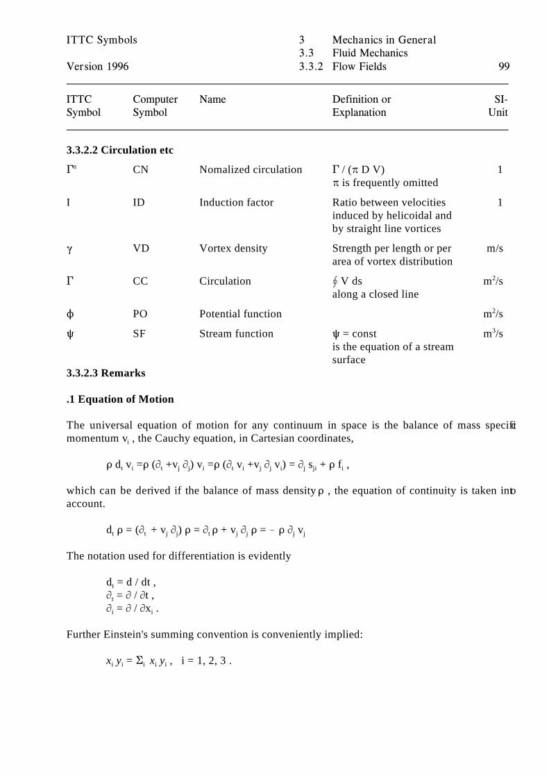
ITTC Symbols 3 Mechanics in General3.3 Fluid Mechanics
Version 1996 3.3.2 Flow Fields 99
ITTC Computer Name Definition or SI-Symbol Symbol Explanation Unit
3.3.2.2 Circulation etc
' CN Nomalized circulation ' / (B D V) 1n
B is frequently omitted
I ID Induction factor Ratio between velocities 1induced by helicoidal andby straight line vortices
( VD Vortex density Strength per length or per m/sarea of vortex distribution
' CC Circulation Š V ds m /salong a closed line
2
N PO Potential function m /s2
R SF Stream function R = const m /sis the equation of a streamsurface
3
3.3.2.3 Remarks
.1 Equation of Motion
The universal equation of motion for any continuum in space is the balance of mass specificmomentum v , the Cauchy equation, in Cartesian coordinates,i
D d v =D (M +v M ) v =D (M v +v M v ) = M s + D f ,t i t j j i t i j j i j ji i
which can be derived if the balance of mass density D , the equation of continuity is taken intoaccount.
d D = (M + v M ) D = M D + v M D = ! D M vt t j j t j j j j
The notation used for differentiation is evidently
d = d / dt ,t
M = M / Mt ,t
M = M / Mx .i i
Further Einstein's summing convention is conveniently implied:
x y = G x y , i = 1, 2, 3 .i i i i i
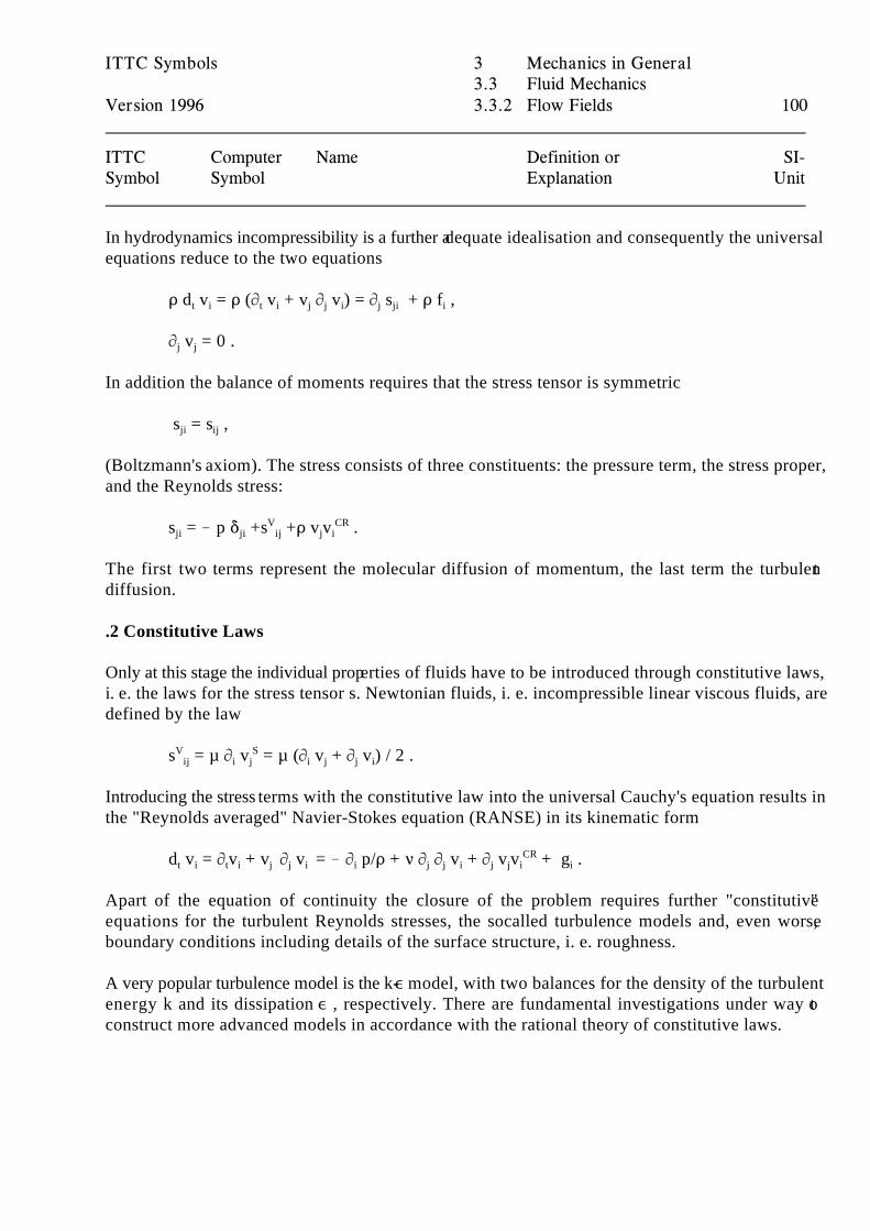
ITTC Symbols 3 Mechanics in General3.3 Fluid Mechanics
Version 1996 3.3.2 Flow Fields 100
ITTC Computer Name Definition or SI-Symbol Symbol Explanation Unit
In hydrodynamics incompressibility is a further adequate idealisation and consequently the universalequations reduce to the two equations
D d v = D (M v + v M v ) = M s + D f ,t i t i j j i j ji i
M v = 0 .j j
In addition the balance of moments requires that the stress tensor is symmetric
s = s ,ji ij
(Boltzmann's axiom). The stress consists of three constituents: the pressure term, the stress proper,and the Reynolds stress:
s = ! p * +s +D v v .ji ji ij j iV CR
The first two terms represent the molecular diffusion of momentum, the last term the turbulentdiffusion.
.2 Constitutive Laws
Only at this stage the individual properties of fluids have to be introduced through constitutive laws,i. e. the laws for the stress tensor s. Newtonian fluids, i. e. incompressible linear viscous fluids, aredefined by the law
s = µ M v = µ (M v + M v ) / 2 .V Sij i j i j j i
Introducing the stress terms with the constitutive law into the universal Cauchy's equation results inthe "Reynolds averaged" Navier-Stokes equation (RANSE) in its kinematic form
d v = M v + v M v = ! M p/D + < M M v + M v v + g .t i t i j j i i j j i j j i iCR
Apart of the equation of continuity the closure of the problem requires further "constitutive"equations for the turbulent Reynolds stresses, the socalled turbulence models and, even worse,boundary conditions including details of the surface structure, i. e. roughness.
A very popular turbulence model is the k-, model, with two balances for the density of the turbulentenergy k and its dissipation , , respectively. There are fundamental investigations under way toconstruct more advanced models in accordance with the rational theory of constitutive laws.
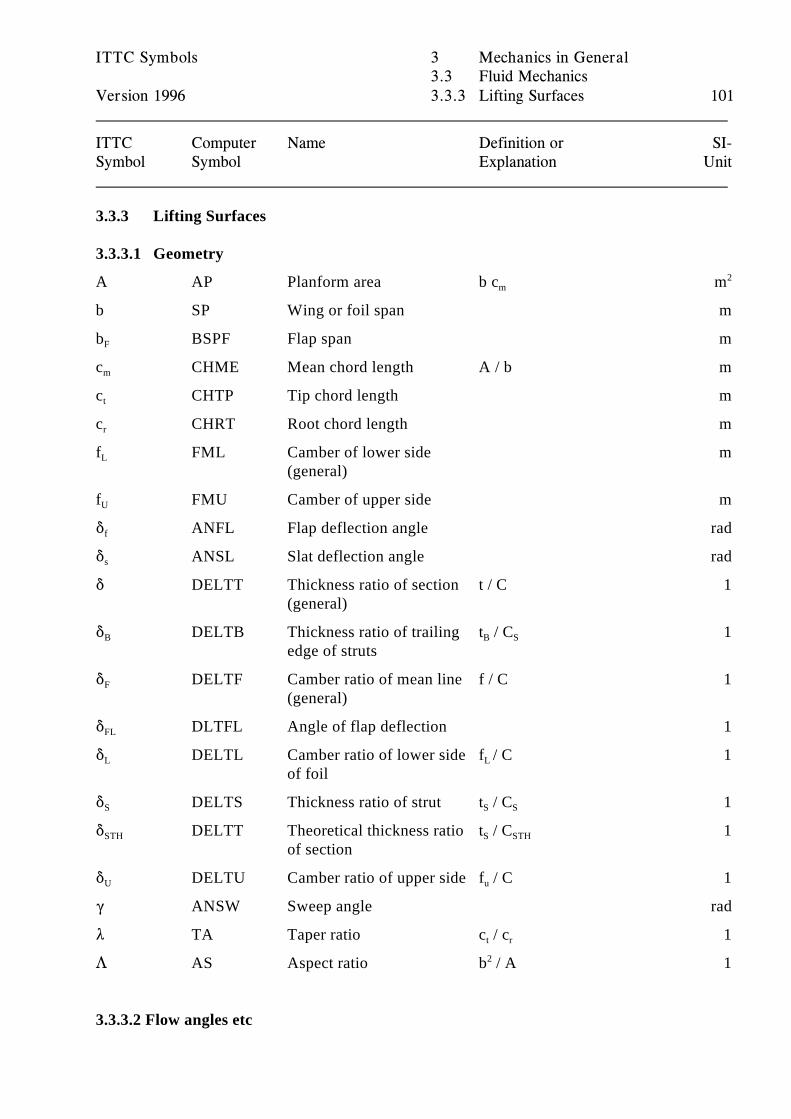
ITTC Symbols 3 Mechanics in General3.3 Fluid Mechanics
Version 1996 3.3.3 Lifting Surfaces 101
ITTC Computer Name Definition or SI-Symbol Symbol Explanation Unit
3.3.3 Lifting Surfaces
3.3.3.1 Geometry
A AP Planform area b c mm2
b SP Wing or foil span m
b BSPF Flap span mF
c CHME Mean chord length A / b mm
c CHTP Tip chord length mt
c CHRT Root chord length mr
f FML Camber of lower side mL
(general)
f FMU Camber of upper side mU
* ANFL Flap deflection angle radf
* ANSL Slat deflection angle rads
* DELTT Thickness ratio of section t / C 1(general)
* DELTB Thickness ratio of trailing t / C 1B
edge of strutsB S
* DELTF Camber ratio of mean line f / C 1F
(general)
* DLTFL Angle of flap deflection 1FL
* DELTL Camber ratio of lower side f / C 1L
of foilL
* DELTS Thickness ratio of strut t / C 1S S S
* DELTT Theoretical thickness ratio t / C 1STH
of sectionS STH
* DELTU Camber ratio of upper side f / C 1U u
( ANSW Sweep angle rad
8 TA Taper ratio c / c 1t r
7 AS Aspect ratio b / A 12
3.3.3.2 Flow angles etc
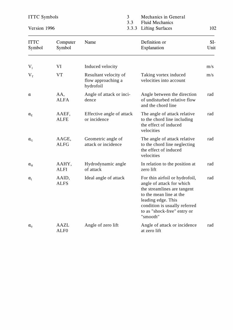
ITTC Symbols 3 Mechanics in General3.3 Fluid Mechanics
Version 1996 3.3.3 Lifting Surfaces 102
ITTC Computer Name Definition or SI-Symbol Symbol Explanation Unit
V VI Induced velocity m/sI
V VT Resultant velocity of Taking vortex induced m/sT
flow approaching a velocities into accounthydrofoil
" AA, Angle of attack or inci- Angle between the direction radALFA dence of undisturbed relative flow
and the chord line
" AAEF, Effective angle of attack The angle of attack relative radE
ALFE or incidence to the chord line includingthe effect of inducedvelocities
" AAGE, Geometric angle of The angle of attack relative radG
ALFG attack or incidence to the chord line neglectingthe effect of inducedvelocities
" AAHY, Hydrodynamic angle In relation to the position at radH
ALFI of attack zero lift
" AAID, Ideal angle of attack For thin airfoil or hydrofoil, radI
ALFS angle of attack for whichthe streamlines are tangentto the mean line at theleading edge. Thiscondition is usually referredto as "shock-free" entry or"smooth"
" AAZL Angle of zero lift Angle of attack or incidence rad0
ALF0 at zero lift
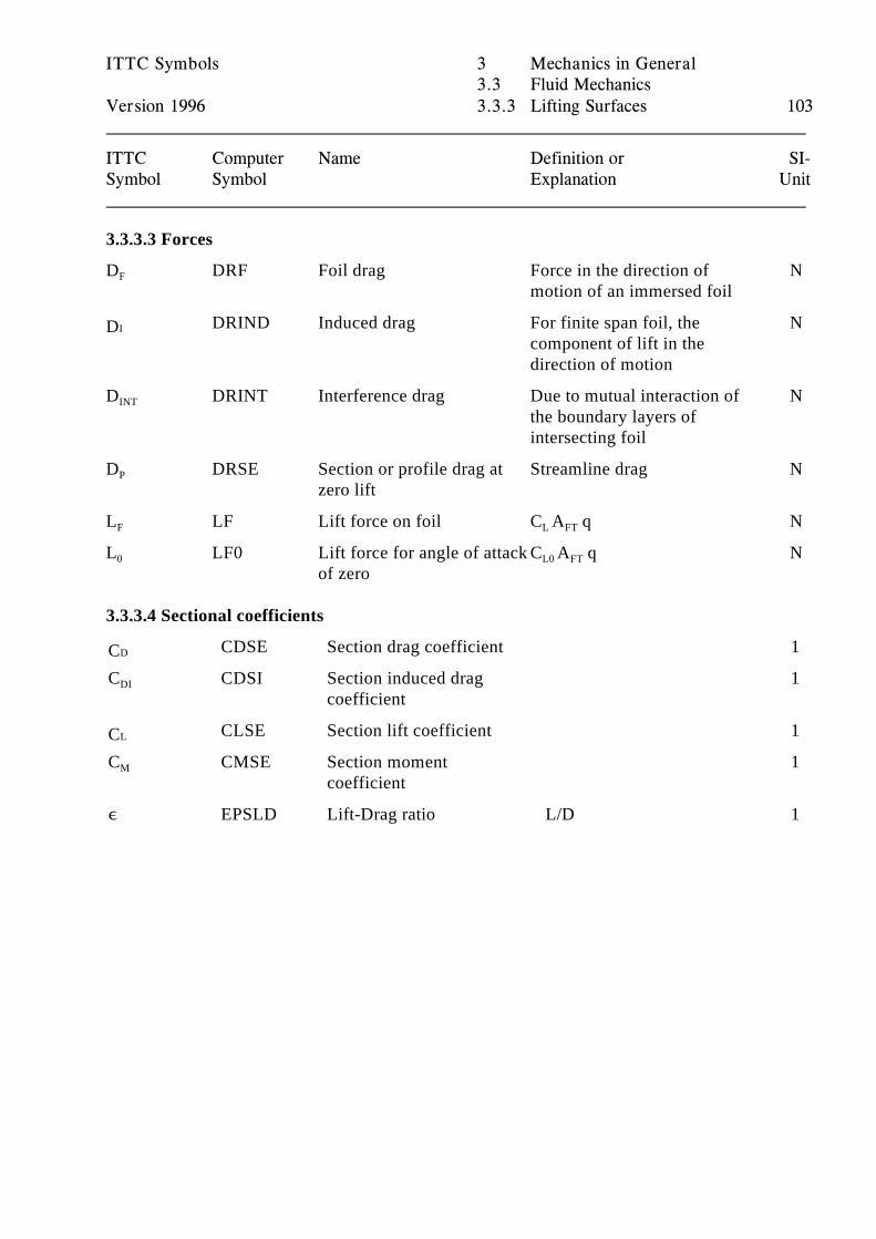
ITTC Symbols 3 Mechanics in General3.3 Fluid Mechanics
Version 1996 3.3.3 Lifting Surfaces 103
ITTC Computer Name Definition or SI-Symbol Symbol Explanation Unit
3.3.3.3 Forces
D DRF Foil drag Force in the direction of NF
motion of an immersed foil
DRIND Induced drag For finite span foil, the NIDcomponent of lift in thedirection of motion
D DRINT Interference drag Due to mutual interaction of NINT
the boundary layers ofintersecting foil
D DRSE Section or profile drag at Streamline drag NP
zero lift
L LF Lift force on foil C A q NF L FT
L LF0 Lift force for angle of attack C A q N0
of zeroL0 FT
3.3.3.4 Sectional coefficients
CDSE Section drag coefficient 1DCC CDSI Section induced drag 1DI
coefficient
CLSE Section lift coefficient 1LCC CMSE Section moment 1M
coefficient
, EPSLD Lift-Drag ratio L/D 1
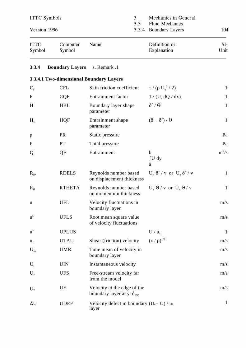
ITTC Symbols 3 Mechanics in General3.3 Fluid Mechanics
Version 1996 3.3.4 Boundary Layers 104
ITTC Computer Name Definition or SI-Symbol Symbol Explanation Unit
3.3.4 Boundary Layers s. Remark .1
3.3.4.1 Two-dimensional Boundary Layers
C CFL Skin friction coefficient J / (D U / 2) 1f e2
F CQF Entrainment factor 1 / (U dQ / dx) 1e
H HBL Boundary layer shape * / 1 1parameter
*
H HQF Entrainment shape (* ! * ) / 1 1E
parameter
*
p PR Static pressure Pa
P PT Total pressure Pa
Q QF Entrainment b m /sIU dy a
2
R RDELS Reynolds number based U * / < or U * / < 1**
on displacement thickness4 e
* *
R RTHETA Reynolds number based U 1 / < or U 1 / < 12
on momentum thickness4 e
u UFL Velocity fluctuations in m/sboundary layer
u UFLS Root mean square value m/ss
of velocity fluctuations
u UPLUS U / u 1+J
u UTAU Shear (friction) velocity (J / D) m/sJ1/2
U UMR Time mean of velocity in m/sm
boundary layer
U UIN Instantaneous velocity m/si
U UFS Free-stream velocity far m/s4
from the model
UE Velocity at the edge of the m/seUboundary layer at y=*995
1layer
e J)U UDEF Velocity defect in boundary (U ! U) / u
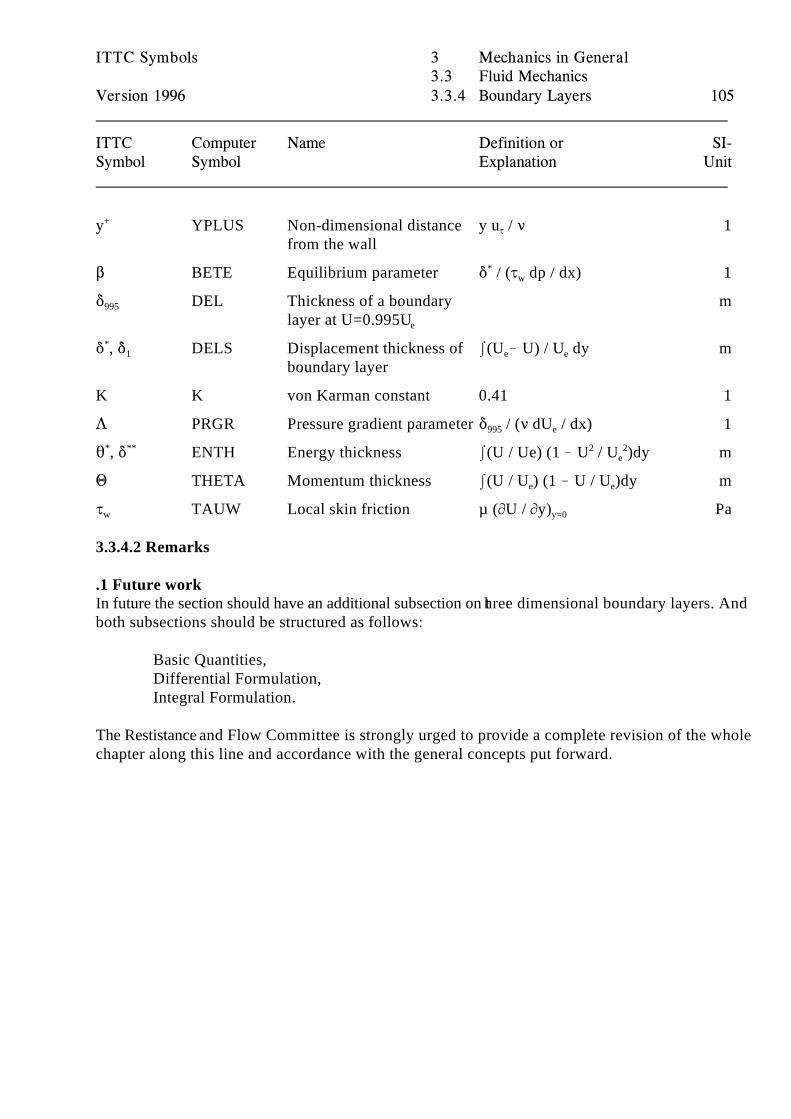
ITTC Symbols 3 Mechanics in General3.3 Fluid Mechanics
Version 1996 3.3.4 Boundary Layers 105
ITTC Computer Name Definition or SI-Symbol Symbol Explanation Unit
y YPLUS Non-dimensional distance y u / < 1+
from the wallJ
$ BETE Equilibrium parameter * / (J dp / dx) 1*w
* DEL Thickness of a boundary m995
layer at U=0.995Ue
* , * DELS Displacement thickness of I(U ! U) / U dy m*1
boundary layere e
K K von Karman constant 0.41 1
7 PRGR Pressure gradient parameter * / (< dU / dx) 1995 e
2 , * ENTH Energy thickness I(U / Ue) (1 ! U / U )dy m* ** 2 2e
1 THETA Momentum thickness I(U / U ) (1 ! U / U )dy me e
J TAUW Local skin friction µ (MU / My) Paw y=0
3.3.4.2 Remarks
.1 Future workIn future the section should have an additional subsection on three dimensional boundary layers. Andboth subsections should be structured as follows:
Basic Quantities,Differential Formulation,Integral Formulation.
The Restistance and Flow Committee is strongly urged to provide a complete revision of the wholechapter along this line and accordance with the general concepts put forward.
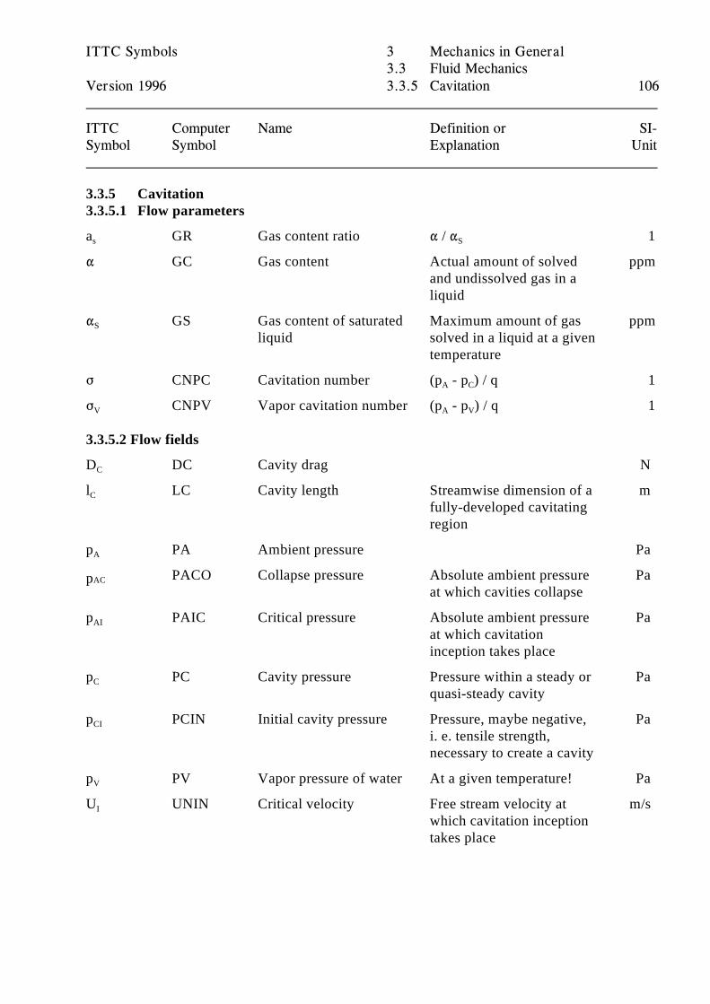
ITTC Symbols 3 Mechanics in General3.3 Fluid Mechanics
Version 1996 3.3.5 Cavitation 106
ITTC Computer Name Definition or SI-Symbol Symbol Explanation Unit
3.3.5 Cavitation3.3.5.1 Flow parameters
a GR Gas content ratio " / " 1s S
" GC Gas content Actual amount of solved ppmand undissolved gas in aliquid
" GS Gas content of saturated Maximum amount of gas ppmS
liquid solved in a liquid at a giventemperature
F CNPC Cavitation number (p - p ) / q 1A C
F CNPV Vapor cavitation number (p - p ) / q 1V A V
3.3.5.2 Flow fields
D DC Cavity drag NC
l LC Cavity length Streamwise dimension of a mC
fully-developed cavitatingregion
p PA Ambient pressure PaA
PACO Collapse pressure Absolute ambient pressure PaACpat which cavities collapse
p PAIC Critical pressure Absolute ambient pressure PaAI
at which cavitationinception takes place
p PC Cavity pressure Pressure within a steady or PaC
quasi-steady cavity
p PCIN Initial cavity pressure Pressure, maybe negative, PaCI
i. e. tensile strength,necessary to create a cavity
p PV Vapor pressure of water At a given temperature! PaV
U UNIN Critical velocity Free stream velocity at m/sI
which cavitation inceptiontakes place
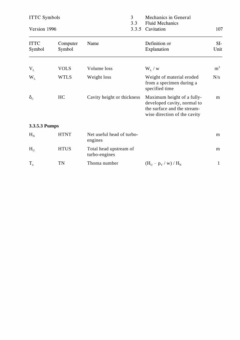
ITTC Symbols 3 Mechanics in General3.3 Fluid Mechanics
Version 1996 3.3.5 Cavitation 107
ITTC Computer Name Definition or SI-Symbol Symbol Explanation Unit
V VOLS Volume loss W / w mL L3
W WTLS Weight loss Weight of material eroded N/sL
from a specimen during aspecified time
* HC Cavity height or thickness Maximum height of a fully- mC
developed cavity, normal tothe surface and the stream-wise direction of the cavity
3.3.5.3 Pumps
H HTNT Net useful head of turbo- mN
engines
H HTUS Total head upstream of mU
turbo-engines
T TN Thoma number (H ! p / w) / H 1n U V N
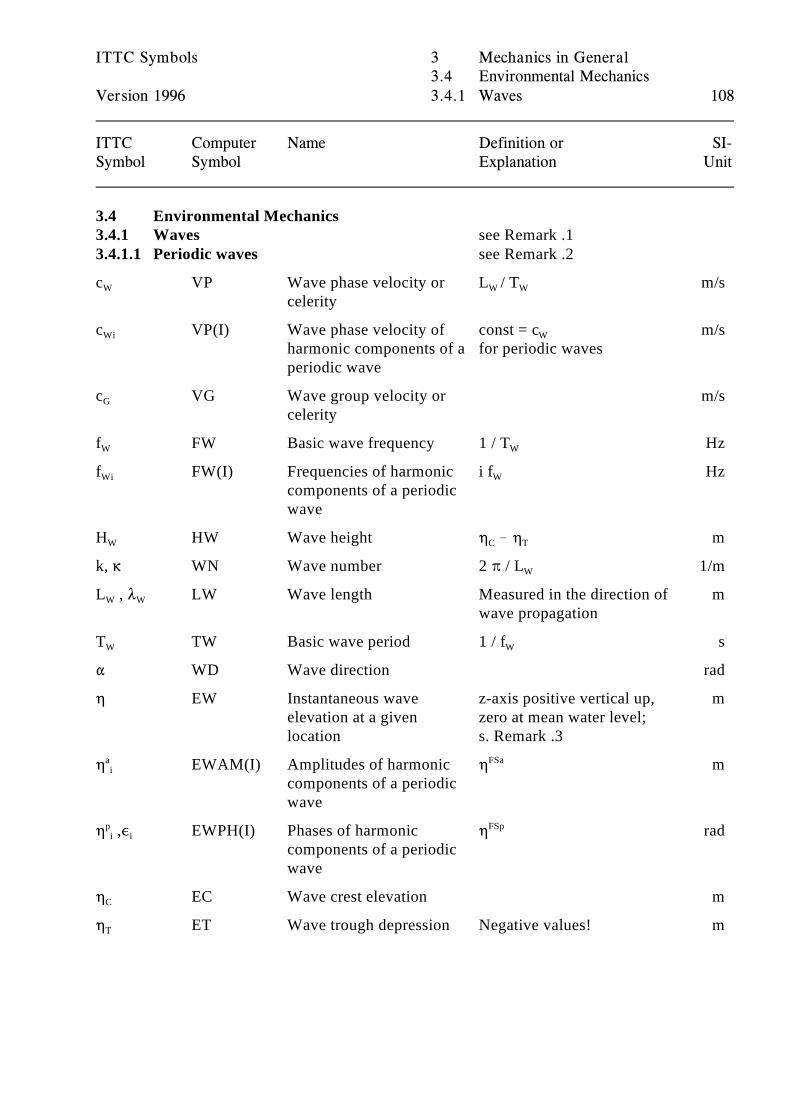
ITTC Symbols 3 Mechanics in General3.4 Environmental Mechanics
Version 1996 3.4.1 Waves 108
ITTC Computer Name Definition or SI-Symbol Symbol Explanation Unit
3.4 Environmental Mechanics3.4.1 Waves see Remark .13.4.1.1 Periodic waves see Remark .2
c VP Wave phase velocity or L / T m/sW
celerityW W
c VP(I) Wave phase velocity of const = c m/sWi
harmonic components of a for periodic wavesperiodic wave
W
c VG Wave group velocity or m/sG
celerity
f FW Basic wave frequency 1 / T HzW W
f FW(I) Frequencies of harmonic i f HzWi
components of a periodicwave
W
H HW Wave height 0 ! 0 mW C T
k, 6 WN Wave number 2 B / L 1/mW
L , 8 LW Wave length Measured in the direction of mW W
wave propagation
T TW Basic wave period 1 / f sW W
" WD Wave direction rad
0 EW Instantaneous wave z-axis positive vertical up, melevation at a given zero at mean water level;location s. Remark .3
0 EWAM(I) Amplitudes of harmonic 0 mai
components of a periodicwave
FSa
0 ,, EWPH(I) Phases of harmonic 0 radpi i
components of a periodicwave
FSp
0 EC Wave crest elevation mC
0 ET Wave trough depression Negative values! mT
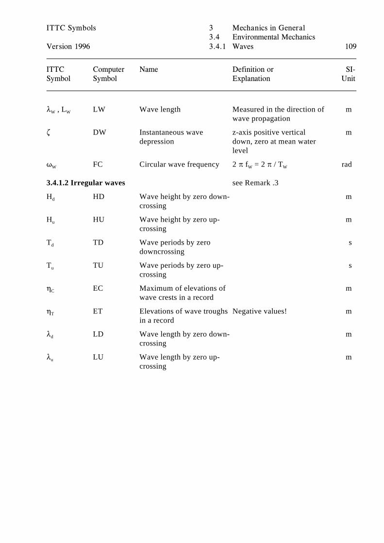
ITTC Symbols 3 Mechanics in General3.4 Environmental Mechanics
Version 1996 3.4.1 Waves 109
ITTC Computer Name Definition or SI-Symbol Symbol Explanation Unit
8 , L LW Wave length Measured in the direction of mW W
wave propagation
. DW Instantaneous wave z-axis positive vertical mdepression down, zero at mean water
level
T FC Circular wave frequency 2 B f = 2 B / T radW W W
3.4.1.2 Irregular waves see Remark .3
H HD Wave height by zero down- md
crossing
H HU Wave height by zero up- mu
crossing
T TD Wave periods by zero sd
downcrossing
T TU Wave periods by zero up- su
crossing
0 EC Maximum of elevations of mC
wave crests in a record
0 ET Elevations of wave troughs Negative values! mT
in a record
8 LD Wave length by zero down- md
crossing
8 LU Wave length by zero up- mu
crossing
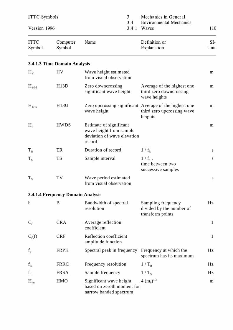
ITTC Symbols 3 Mechanics in General3.4 Environmental Mechanics
Version 1996 3.4.1 Waves 110
ITTC Computer Name Definition or SI-Symbol Symbol Explanation Unit
3.4.1.3 Time Domain Analysis
H HV Wave height estimated mV
from visual observation
H H13D Zero downcrossing Average of the highest one m1/3d
significant wave height third zero downcrossingwave heights
H H13U Zero upcrossing significant Average of the highest one m1/3u
wave height third zero upcrossing waveheights
H HWDS Estimate of significant mF
wave height from sampledeviation of wave elevationrecord
T TR Duration of record 1 / f sR R
T TS Sample interval 1 / f , sS S
time between twosuccessive samples
T TV Wave period estimated sV
from visual observation
3.4.1.4 Frequency Domain Analysis
b B Bandwidth of spectral Sampling frequency Hzresolution divided by the number of
transform points
C CRA Average reflection 1r
coefficient
C (f) CRF Reflection coefficient 1r
amplitude function
f FRPK Spectral peak in frequency Frequency at which the HzP
spectrum has its maximum
f FRRC Frequency resolution 1 / T HzR R
f FRSA Sample frequency 1 / T HzS S
H HMO Significant wave height 4 (m ) mmo
based on zeroth moment fornarrow banded spectrum
01/2
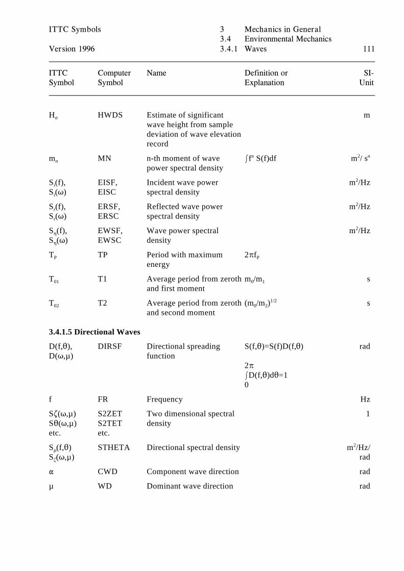
ITTC Symbols 3 Mechanics in General3.4 Environmental Mechanics
Version 1996 3.4.1 Waves 111
ITTC Computer Name Definition or SI-Symbol Symbol Explanation Unit
H HWDS Estimate of significant mF
wave height from sampledeviation of wave elevationrecord
m MN n-th moment of wave If S(f)df m / sn
power spectral density
n 2 n
S (f), EISF, Incident wave power m /Hzi
S (T) EISC spectral densityi
2
S (f), ERSF, Reflected wave power m /Hzr
S (T) ERSC spectral densityr
2
S (f), EWSF, Wave power spectral m /Hz0
S (T) EWSC density0
2
T TP Period with maximum 2BfP
energyP
T T1 Average period from zeroth m /m s01
and first moment0 1
T T2 Average period from zeroth (m /m ) s02
and second moment0 2
1/2
3.4.1.5 Directional Waves
D(f,2), DIRSF Directional spreading S(f,2)=S(f)D(f,2) radD(T,µ) function
2B ID(f,2)d2=1 0
f FR Frequency Hz
S.(T,µ) S2ZET Two dimensional spectral 1S2(T,µ) S2TET densityetc. etc.
S (f,2) STHETA Directional spectral density m /Hz/D
S (T,µ) rad.
2
" CWD Component wave direction rad
µ WD Dominant wave direction rad
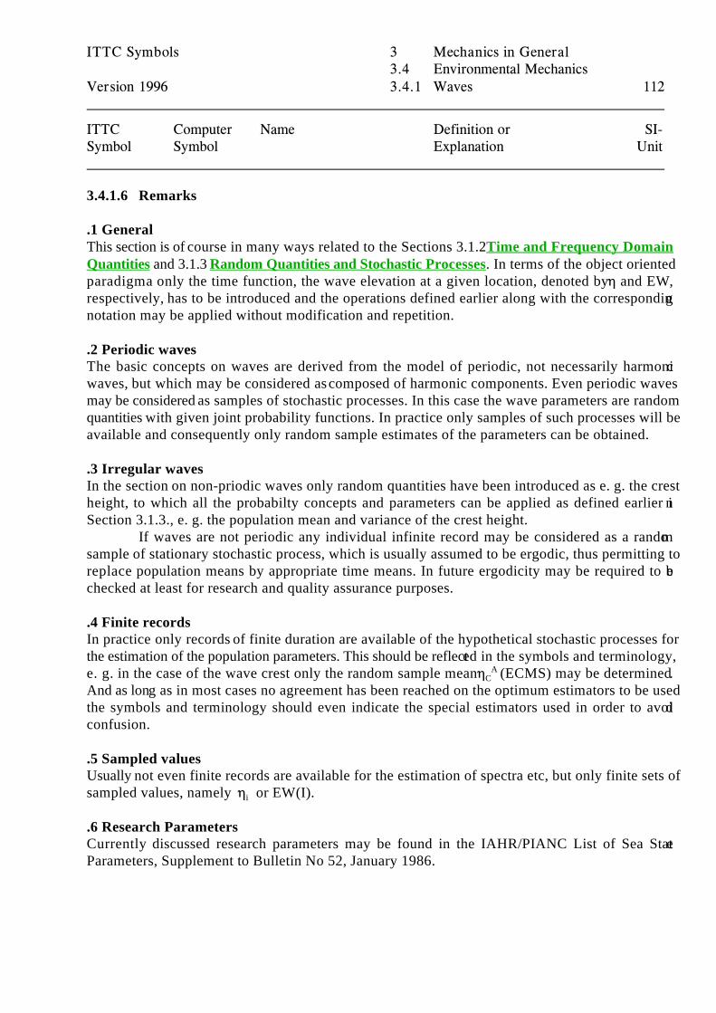
ITTC Symbols 3 Mechanics in General3.4 Environmental Mechanics
Version 1996 3.4.1 Waves 112
ITTC Computer Name Definition or SI-Symbol Symbol Explanation Unit
3.4.1.6 Remarks
.1 GeneralThis section is of course in many ways related to the Sections 3.1.2 Time and Frequency DomainQuantities and 3.1.3 Random Quantities and Stochastic Processes. In terms of the object orientedparadigma only the time function, the wave elevation at a given location, denoted by 0 and EW,respectively, has to be introduced and the operations defined earlier along with the correspondingnotation may be applied without modification and repetition.
.2 Periodic wavesThe basic concepts on waves are derived from the model of periodic, not necessarily harmonicwaves, but which may be considered as composed of harmonic components. Even periodic wavesmay be considered as samples of stochastic processes. In this case the wave parameters are randomquantities with given joint probability functions. In practice only samples of such processes will beavailable and consequently only random sample estimates of the parameters can be obtained.
.3 Irregular wavesIn the section on non-priodic waves only random quantities have been introduced as e. g. the crestheight, to which all the probabilty concepts and parameters can be applied as defined earlier inSection 3.1.3., e. g. the population mean and variance of the crest height.
If waves are not periodic any individual infinite record may be considered as a randomsample of stationary stochastic process, which is usually assumed to be ergodic, thus permitting toreplace population means by appropriate time means. In future ergodicity may be required to bechecked at least for research and quality assurance purposes.
.4 Finite recordsIn practice only records of finite duration are available of the hypothetical stochastic processes forthe estimation of the population parameters. This should be reflected in the symbols and terminology,e. g. in the case of the wave crest only the random sample mean 0 (ECMS) may be determined.C
A
And as long as in most cases no agreement has been reached on the optimum estimators to be usedthe symbols and terminology should even indicate the special estimators used in order to avoidconfusion.
.5 Sampled valuesUsually not even finite records are available for the estimation of spectra etc, but only finite sets ofsampled values, namely 0 or EW(I).i
.6 Research ParametersCurrently discussed research parameters may be found in the IAHR/PIANC List of Sea StateParameters, Supplement to Bulletin No 52, January 1986.
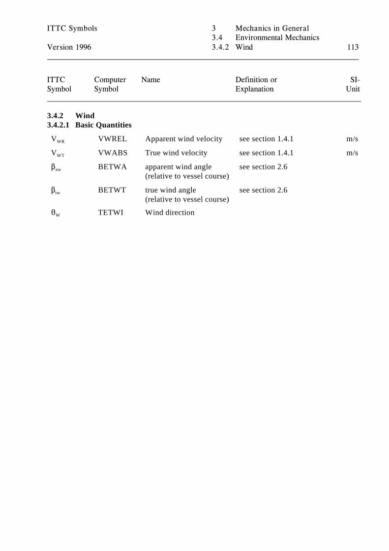
ITTC Symbols 3 Mechanics in General3.4 Environmental Mechanics
Version 1996 3.4.2 Wind 113
ITTC Computer Name Definition or SI-Symbol Symbol Explanation Unit
3.4.2 Wind3.4.2.1 Basic Quantities
V VWREL Apparent wind velocity see section 1.4.1 m/sWR
V VWABS True wind velocity see section 1.4.1 m/sWT
$ BETWA apparent wind angle see section 2.6aw
(relative to vessel course)
$ BETWT true wind angle see section 2.6tw
(relative to vessel course)
2 TETWI Wind directionW
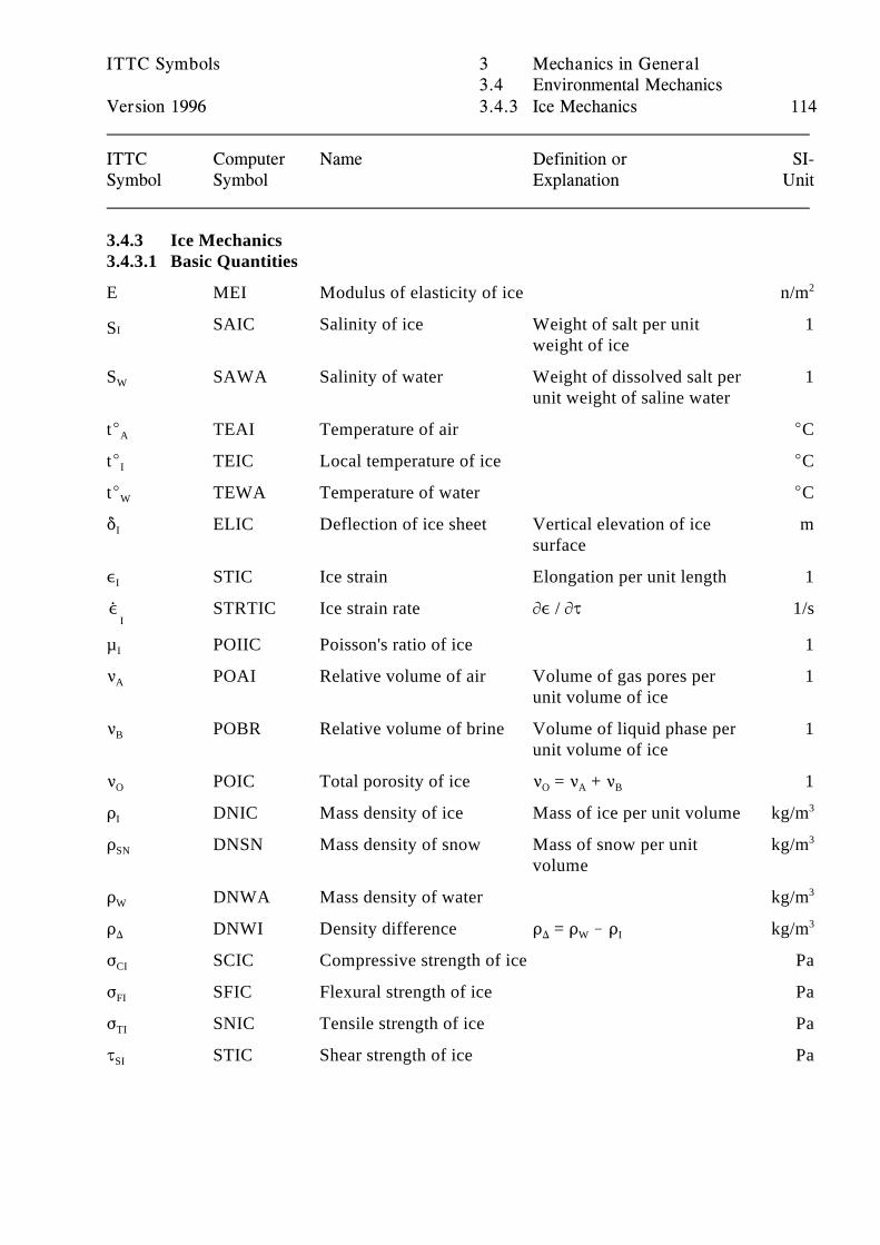
,
ITTC Symbols 3 Mechanics in General3.4 Environmental Mechanics
Version 1996 3.4.3 Ice Mechanics 114
ITTC Computer Name Definition or SI-Symbol Symbol Explanation Unit
3.4.3 Ice Mechanics3.4.3.1 Basic Quantities
E MEI Modulus of elasticity of ice n/m2
SAIC Salinity of ice Weight of salt per unit 1ISweight of ice
S SAWA Salinity of water Weight of dissolved salt per 1W
unit weight of saline water
tE TEAI Temperature of air ECA
tE TEIC Local temperature of ice ECI
tE TEWA Temperature of water ECW
* ELIC Deflection of ice sheet Vertical elevation of ice mI
surface
, STIC Ice strain Elongation per unit length 1I
ISTRTIC Ice strain rate M, / MJ 1/s
µ POIIC Poisson's ratio of ice 1I
< POAI Relative volume of air Volume of gas pores per 1A
unit volume of ice
< POBR Relative volume of brine Volume of liquid phase per 1B
unit volume of ice
< POIC Total porosity of ice < = < + < 1O O A B
D DNIC Mass density of ice Mass of ice per unit volume kg/mI3
D DNSN Mass density of snow Mass of snow per unit kg/mSN
volume
3
D DNWA Mass density of water kg/mW3
D DNWI Density difference D = D ! D kg/m) ) W I3
F SCIC Compressive strength of ice PaCI
F SFIC Flexural strength of ice PaFI
F SNIC Tensile strength of ice PaTI
J STIC Shear strength of ice PaSI
ITTC Symbols 4 Background and References4.1 Symbols and Terminology Group
Version 1996 115
4 Background and References
4.1 Symbols and Terminology Group
4.1.1 Terms of Reference
In May 1985 the Executive Committee of the 18th International Towing Tank Conference (ITTC)reorganised the former Information Committee, earlier Presentation Committee, to form a Symbolsand Terminology (SaT) Group in the newly established ITTC Secretariat.
The task of the SaT Group for the 18th ITTC was to carry out Recommendations 1 through 5, relatedto the ITTC Standard Symbols, of the Information Committee of the 17th ITTC, which were:
1. The Information Committee should continue to monitor and co-ordinate the developmentof new symbols by the Technical Committees.
2. The Conference should adopt the new symbols for hydrostatics included in Appendix 4and the Information Committee should then include these in the ITTC Standard Symbols.
3. The Information Committee should restructure the ITTC Standard Symbols according tothe outline Proposal in Appendix 6 and include new symbols agreed by the TechnicalCommittees.
4. The Information Committee should continue to revise the Dictionary of ShipHydrodynamics as required.
5. The Information Committee shoud continue cooperation with other organizations toachieve a common agreement on symbols and terminology.
The 18th ITTC at Kobe adopted the following Recommendations to the Conference and for the futurework of the SaT Group, respectively, related to Symbols:
Recommendations to the Conference :
1. The Conference should adopt the structure of the ITTC standard Symbols and Termino-logy List outlined by the Symbols and Terminology Group and used as the basis for the 1987Draft List distributed at the 18th ITTC in Kobe.
2. The Conference should urge the Technical Committees and individuals to contribute tothe completion of the List of Standard Symbols and should encourage the use of the symbolsand their further development in cooperation with the Symbols and Terminology Group.
3. The Conference should decide to delay the review and update of the ITTC Dictionary ofShip Hydodynamics and the official translations of this into principal languages until the finalSymbols and Terminology List is published in 1990.
Recommendations for the future work of the Group :
ITTC Symbols 4 Background and References4.1 Symbols and Terminology Group
Version 1996 116
1. The Symbols and Terminology Group should continue cooperation with otherorganizations to achieve a common agreement on symbols and terminology.
2. The Symbols and Terminology Group should continue to monitor and coordinate thedevelopment of new symbols and terminology by the Technical Committees of the ITTC.
3. The Symbols and Terminology Group should complete the ITTC Standard Symbols andTerminology List based on the 1987 Draft distributed at the 18th ITTC and distribute thefinal version with Volume 1 at the Proceedings of the 19th ITTC.
Finally the 19th ITTC at Madrid adopted the following recommendations related to symbols:
Recommendations to the Conferences :
The 1990 version of the List of Standard symbols should be used as a working documentwithout the formal approval of the Conference.
Recommendations for the future work of the Group :
The SaT Group to put the computer compatible symbols on a more rational basis in orderto make them useful for data exchange puposes.
4.1.2 Activities of the SaT Group
The SaT Group took up its work immediately after it was established having its first meeting atWageningen in October 1985, and coming up with the plan to produce the present draft of arestructured and enlarged list of the ITTC Standard Symbols 1987. The first raw draft was discussedat Berkeley in July 1986, the Draft 1987 published at the 18th ITTC in October 1987 at Kobe by theSociety of Naval Architects of Japan, having been finalized at Trondheim in June 1987.
Work on various chapters has been continued by the 18th ITTC SaT Group and the results have beendistributed to the Technical Committees at the Kobe Conference together with the printed Draft 1987.
The SaT Group of the 19th ITTC continued work on the Standard Symbols during meetings at Genovain March 1988, at the Hague and Berlin in September 1988 and in August 1989 at Trondheim, the1990 version being completed at Genova in March 1990.
During this work, new and more rigorous requirements resulting from the proposed use of thesymbols in validation work and in data bases caused a reconsideration of the fundamental aspects.Duplication of computer symbols had to be carefully traced and avoided, in order to permit automatichandling of symbols in data bases.
In order to facilitate the handling of the List of Symbols the earlier version was retyped as a seriesof WordPerfect files, which were available much too late for updating and were printed without evenhaving been proof read! Consequently, the goal of finalizing the symbols list before the 19th ITTCat Madrid could not be reached. From the document itself it is evident that was less than a draft.
ITTC Symbols 4 Background and References4.1 Symbols and Terminology Group
Version 1996 117
The SaT Group of the 20th ITTC met at Madrid in September 1990, at Berlin in June 1991, atNewcastle in May 1992 and at Genova in January 1993. The primary task after many years offrustrations with the computerized list of symbols was to finally establish a computer implementationpermitting direct expert corrections on a PC.
After the previous transscription into the WordPerfect files using the tabulator function the solutionwas achieved by transformation to the table format. With the appropriate tools being available afterall the next task tackled was to correct all the misprints and to implement all the improvementssuggested by colleagues of member organisations and members of the SaT Group. The List ofSymbols as printed is now available on a floppy discs using the format of a WordPerfect 5.2 masterdocument with the appropriate subdocuments, being themselves master documents according to thestructure of the list.
The main concern after this still rather traditional approach was to achieve the goal set out in theRecommendations for the future work of the SaT Group, to put the computer symbols on a morerational basis. And it soon became evident that the accomplishment of this task could only be achievedby rigorously following the object oriented paradigma applied earlier in restructuring the List ofSymbols. The basic principles and rules behind this work are outlined in the following chapters ofthis preface.
Two problems had to be solved: to maintain the traditional, in many ways inconsistent "Standard"Symbols as an accepted interim and suggest new consistent symbols as alternatives. Some of theseare already used in computer work and SaT Group feels that due to their efficiency they will sooneror later completely replace the traditional symbols as has the system of SI-Units the traditionalsystems.
In view of the increasing demands concerning quality assurance systems the SaT Group felt that theITTC Symbols should no longer be called Standard Symbols as this name implies legal obligations,which are not existent. The International Standard Organisation and corresponding nationalorganisations may at a later stage take measures to adopt the ITTC Symbols as a Standard as wasalready intended with the earlier version; s. 4.5.3.
During the work to rationalize the computer compatible symbols for use in databases etc the SaTGroup became aware of a number of related efforts on an even more general level, which need to betaken into account in the further development of the ITTC Symbols. As documented in the GroupReport to the 20th ITTC the development and and application of terminological databases isdramatically increasing and has lead to a number of specialized workshops and symposia.
In the broadest sense terminological databases are basic for computer aided knowledge and scienceengineering, which are developing at a breath taking pace. In order to meet the forthcomingrequirements the ITTC Symbols will have to be further rigorously rationalized. Compared to thisformidable task, which has only been started with the new object oriented structure of the SymbolsList, the transformation from the present table format into one of the rapidly developingterminological database formats appears to be a minor task.
The software systems presently available do still not meet very basic requirements, as did the wordprocessors up to now, absorbing too much of the energy of the SaT Group which should have been
ITTC Symbols 4 Background and References4.1 Symbols and Terminology Group
Version 1996 118
devoted to the symbols proper. While the problem of producing customized lists of symbols can besolved rather easily, the much more interesting problem of deriving consistent submodels from thegeneral models of the complete list needs still much more development work.
At this stage, it is appropriate to acknowledge with thanks the tremendous work done by the formerPresentation and Information Committees and the Technical Committees in their respective fields. Itis only on the basis of their work that the task of the SaT Group could have been undertaken and canbe carried on. Last but not least a word of thanks is due to the great number of typists who have atall stages contributed to the actual production of the document.
All the ITTC Communnity, the Technical Committees in particular are invited to contribute to thecontinuing task of updating and further improvement.
4.1.3 Membership
The membership of the SaT Group as appointed by the 18th ITTC Executive Committee in May1985 and re-appointed by the 19th ITTC Executive Committee in October 1987 is as follows:
Prof. Bruce Johnson (Chairman)Naval Architecture, Ocean and Marine Engineering Department 590 Holloway Road, U.S. Naval AcademyAnnapolis, MD 21402,USAPhone +1 410 293 6457Internet: [email protected] +1 410 293 2219
Dr. David ClarkeDepartment of Marine TechnologyUniversity of Newcastle upon TyneNewcastle upon Tyne, NE1 7RU, United KingdomPhone +44 91 222 6721Fax +44 91 261 1182
Dr. Norihiro MatsumotoElectronics Research CenterNippon Kokan K.K.1-1 Minamiwatarida-cho, Kawasaki-kuKawasaki 210, JapanPhone +81 44 322 6276Fax: +81 44 322 6523
ITTC Symbols 4 Background and References4.1 Symbols and Terminology Group
Version 1996 119
Prof. Carlo Podenzana-Bonvino (Secretary)Dipartimento di Ingegneria Navale e TecnologieMarine (DINAV), Universita di GenovaVia Montallegro 116145 Genova, ItalyPhone +39 10 353 2426/2430Fax +39 10 353 2127
Prof. Michael SchmiechenVersuchsanstalt für Wasserbau und SchiffbauMüller-Breslau-Strasse (Schleuseninsel)10623 Berlin, GermanyPhone +49 30 311 84 270Fax +49 30 311 84 200
Most of the members were re-appointed again by the Executive Committee in September 1990,Dr. Matsumoto being followed by:
Prof. Michio Nakato4-28-7 Kameyama-MinamiAsa-KitaHiroshima 731-02, JapanPhone +81 82 814 5857Fax +81 82 814 7285
and as a new member was appointed:
Dr. Kostadin YossifovBulgarian Ship Hydrodynamics Centre9000 Varna, BulgariaPhone +359 52 776390Fax +359 52 772267
ITTC Symbols 4 Background and References4.2 List of Symbols
Version 1996 120
4.2 List of Symbols
4.2.1 Classification
The prime concern in setting up a revised and enlarged list of ITTC Standard Symbols was todesign an adequate system for the classification of concepts. As soon as the work started itbecame clear that the outline proposed by the Information Committee of the 17th ITTC (Proc.17th ITTC (1984) Vol.1, p.56) had to be reconsidered in view of the problems encountered.
Subsequently the following design requirements and goals have been established:
1. produce a coherent document, meeting the present and possibly the futurerequirements of the ITTC community in general and particular user groups
2. establish an open ended matrix structure that can be easily expanded as requirementsarise, without the need of restructuring and repetition or too many explicit cross-references
3. minimize departures from the well established and widely accepted previous list ofsymbols
After a series of attempts to meet these requirements the structure as listed in the table of contentsevolved very much in line with the past development of the symbols, for instance by the HighSpeed Craft Committee and others. The essential features are the subject areas of rather limitedscope, organized in an hierarchical order. Ideally each subject area represents a complete andcoherent model of that area under consideration, for example rigid body motion, hull geometry,propulsor performance.
4.2.2 Structure
The concepts related to a given subject area or model are designated by the ITTC Symbol andcalled by their Name. Their meaning can in principle only be concluded from the context of themodel, that is by coherent, so called 'implicit' definitions, to be derived from an explicit statementof the model, ideally an axiomatic system or any equivalent, for example a drawing.
The problem is that traditionally in lists of symbols as in dictionaries these explicit models aremissing for various reasons. One reason is that many subject areas under discussion are far frombeing developed and understood to the extent necessary. A consequence of this situation is that thesymbols proposed are not always as coherent as is necessary for advanced and systematic work,where the explicit models and adequate notations area are a prerequisite.
The problem under discussion is of course the same in national and international standards. Inorder to avoid the dilemma indicated, the ITTC Symbols should not only perpetuate past practiceand jargon but try to take the lead and step forward. This is particularly important in view of thedevelopment trends in marine technology. In a rapidly changing world adequate tools areprerequisite for efficient problem solving.
ITTC Symbols 4 Background and References4.2 List of Symbols
Version 1996 121
As expert system and knowledge engineering technologies evolve the importance of adequatesymbols and terminology is more widely acknowledged. The training of scientists working in theterminology field is being offered by the standards organizations. Some of these activities havebeen monitored but are felt to be lacking in clear-cut rules which may be readily understood andapplied in practice.
The original idea to add indices of symbols and names to the document had to be delayed as longas adequate tools were missing. Now such an undertaking is felt to be still premature at thepresent stage, as it requires the resolution of a number of additional problems, such asstandardisation of names.
4.2.3 Organization
As has been emphasized the development of symbols is a continuing process and as the subjectdevelops, further amendments and additions, as approved by the Conference, will be included infuture editions of the list.
In order to avoid any extra problems the symbols are arranged in alphabetical order in eachsubject area as in previous lists. Continuous page numbering was discarded in earlier versions.The idea was to establish a loose leaf organization as the most appropriate, in view of new draftsto be incorporated.
In view of the extremely powerful modern word processing systems the whole idea was discardedand advantage was taken of the indexing cababilities etc. permitting efficient production of realupdates including in future additional explanations and sketches or drawings related to particularsections where necessary, and as found in national and international standards.
But in view of the tremendous effort which explicit mathematical models, explanations, andsketches take for their preparation, the present SaT Group has only started to consider guidelinesfor these additions and has added only few examples of explanations to the present list. TheTechnical Committees and other interested parties are urged to provide further material for reviewby the SaT Group and future inclusion into the list.
It has been noted by the SaT Group that some users dislike the disruption of the list of symbols bylengthly explanations. But the Group feels that the complexity of the subject and the sensible useof the symbols require such explanations, the more so as the fundamentals of the theory of scienceand terminology are not taught to students of naval architecture and marine engineering.
ITTC Symbols 4 Background and References4.3 Principles of Notation
Version 1996 122
4.3 Principles of Notation
4.3.1 Objects: Quantities
Standard notations have to be adequate for the problems to be dealt with and preferably have to beoperational.
In general there is a body b, e. g. ship S or model M, in space s, referred to coordinates c withorigin o, and time t of which the values q of quantities of certain physical qualities Q are ofinterest, i. e.
q = Q (b, s, c, o, t) ,
q is a variable for numerical values of quantities, while Q is a variable for functors constants,quantities of qualities, e. g. of inertia, momentum, or energy.
In many cases the quantities in question are components of vectorial or tensorial quantities; andshould be denoted accordingly, s. 4.3.2.
Further, quite often various aspects of the same quantity are of interest, for example their spectraor aspects of those, in simpler cases just their expectation or estimates of these, e. g. timeaverages, all of them to be carefully distinguished; s. 4.3.3.
It should be evident, that the requirements concerning an adequate, operational notation are quitedemanding. At the same time it should be understood that it is worthwhile to create such anotation, as waste of effort due to confusion of concepts may be reduced drastically.
The question is of course how far one wants to depart from current practice in order to cope withthis situation. The example of the standard notation used in chemistry may serve as a guideline.
In the present context, the typical objects or "elements" referred to are the values of quantities intime or "signals". Consequently the symbols for the signals should be the primary symbol andcomponents and transforms should be denoted by sub- and superscripts, respectively.
4.3.2 Components: Subscripts
In view of vector and tensor components, it is felt that it is appropriate to introduce a simpletensor notation at least for orthogonal coordinates. This helps to limit the number of symbols as itrequires only one symbol for the particular set of components in question. For example thevarious, say at least two times thirty six "stability derivatives", i. e. generalized mass anddamping, need not and cannot be introduced individually.
If vector or tensor components, in general matrix components are conveniently denoted bysubscripts, the above situation thus becomes in more general terms
q = Q (b, s, c, o, t).ij ij
ITTC Symbols 4 Background and References4.3 Principles of Notation
Version 1996 123
Numerical subscripts are truly operational in most algorithmic languages, which can handlematrices, usually called one-, two-, or three-dimensional arrays.
4.3.3 Operators: Superscripts
Superscripts are traditionally used for exponentiation but can be generally used to denoteoperators; the most satisfactory approach being the inverse Polish notation.
The advantage of this notation is that no brackets are required and operators are listed exactly inthe sequence in which they are applied to the signal. As has been done with the matrix notationearlier this notation may in future be readily rendered operational in advanced softwareenvironments, object oriented languages in particular.
For convenience the computer symbols and symbols used in data bases should exactly reflect thisnotation in order to avoid any extra problems of translation. Consequently the earlier proposedprefixes in the computer symbols have been changed to suffixes. As an example the real part ofthe heave spectrum may be denoted as follows:
standard computerdata base XSR3 XSR(3) or X_SR(3) or XxSpRe(3)
XSR3 or X_SR3 or XxSpRe3
The main problem in any case is to define symbols for operations and not for the results of theoperations. In order to have the most compact notation agreement should be reached concerning aone character notation, and a corresponding two character notation for the computer symbols, forwell defined operations.
Due to the fact that it has not been possible to define symbols for concepts, qualifiers, operatorsetc uniformly in terms of two characters the above example show the presently used techniques tointroduce separators. X and Xx denote symbol variables, to be replaced by symbols proper in anyparticular application.
If necessary the meaning of a operator symbol may depend on the context, i.e. its position withrespect to others and the object it operates upon. This generic use of symbols is of course veryefficient, but needs special care not to confuse concepts.
It is most important to note that in any case definitions of concepts or operations should not beconfused with operational definitions, i.e. methods for determination or measurement of values.Separate identifiers have to be introduced in order to avoid confusion. A whole hierarchy of suchoperators and qualifiers is necessary.
Some 'operator' symbols are proposed in the following chapter on fundamental concepts. Theyconcern:
1. identifiers of the object being tested, e. g. ship S or model M, or the various bodies ina multi-body problem,
ITTC Symbols 4 Background and References4.3 Principles of Notation
Version 1996 124
2. identifiers of coordinate systems and of the reference points, not only forward and aftperpendicular,
3. the various aspects of complex quantities,
4. the various aspects of spectra and
5. the various aspects of random quantities and stochastic processes.
So far no particular identifiers have been introduced for various estimators. As an example the powerspectra of stationary random processes may be estimated using Fourier techniques, as agreed uponby the oceanographic institutes world wide, or by autoregressive model techniques, avoidingsystematic i. e. bias errors inherent in the first technique. Another example is the interpretation ofthe conceptual frame-work of hull-propeller interaction based on propulsion, hull resistance, andpropeller open water tests or from the results of propulsion tests alone.
ITTC Symbols 4 Background and References4.4 Details of Notation
Version 1996 125
4.4 Details of Notation
4.4.1 Standard Symbols
The symbols in the first column of the tables are primarily intended for use in technical writing andmathematical expressions. The following notes are relevant:
1. All symbols, their subscripts, and superscripts should be written as shown.
2. In a number of instances alternative symbols are given.
3. In many cases the symbols, their sub- and superscripts denote variables to be replaced bysymbols for any object, component and qualifier or operator, respectively.
4. Where for one reason or another departures from the standard symbols are made, thesedepartures should be clearly indicated and stated.
4.4.2 Computer Symbols
Wherever possible the symbols in the second column of the tables have been chosen so that theirmeaning is readily apparent. They have been constructed from the CCITT International TelegraphAlphabet, restricted character set. They are therefore suitable for use in a wide range of situationse. g.: Telex messages, letters, computer printouts etc.
To ensure that the symbols can be used in a wide range of programming languages they currentlyhave been kept to less than six characters long. The symbols should be used as defined, and, inaccordance with modern programming practice, should have their type explicitly declared before use.The following rules were applied in the derivation of the symbols:
1. Only upper case letter A - Z and digits 0 - 9 have been used.
2. Formerly Greek letters have been spelled out, if necessary in abbreviated form or withchanged spelling. This practice is considered obsolete.
3. The Froude 'circular' symbols are defined by the prefix CIRC.
4. All symbols start with a letter.
5. Qualifiers and operators, preferably two characters, are currently suffixed to the mainsymbol line, without spacing.
6. No one computer compatible symbol should be used for different concepts in a givencontext. This goal has not been completely achieved for the whole list. Ad hoc solutionshave been attempted but discarded as unsatisfactory.
7. Since the computer compatible symbols have been proposed as the basis of attribute namesfor data exchanges, the above rules will probably be further developed in the near future.
ITTC Symbols 4 Background and References4.4 Details of Notation
Version 1996 126
A final remark on the Computer Symbols: in the computer, the letter O and figure 0 (zero) havefundamentally different meanings, but owing to their resemblance they can be easily confused. Thusit is necessary to distinguish rigorously between them. As a matter of fact there are contradictoryconventions being widely used.
4.4.3 Names, Definitions, SI-Units
The third column in the tables contains the names of the concepts denoted by the symbols in the firstand the second columns, while the fourth column usually contains a definition, or a short explanationwhere necessary. The last column gives the SI-Units for the concepts.
The dimensions of dimensionless quantities as well as their units are 1. They are measured in countsor "absolute units", which sometimes are given names, e.g. rad, rev, but this practice, usual innatural languages, is found to be not very useful in formal systems.
A number of concepts and their symbols are customarily defined and/or standardized differently indifferent fields of application. The SaT Group cannot resolve all of these discrepancies, but urges thatin such cases the definitions and the units used are stated. Only a few examples having been discussedmay be mentioned.
While the SI-Units of angle and velocity are rad and meter/second, respectively, the traditional unitsdegree and knot are still widely used and clearly this situation will not change in the near future. Inthe spectral description of real deterministic or stochastic processes spectra and power spectra,respectively may be defined as double- or single-sided as functions of frequency or circularfrequency. Any of these difinitions has its particular advantages, but has to be clearly distinguishedfrom the others.
A major step towards an unambiguous definition of the phase angle has been taken by explicitelydistinguishing phase lead and lag of complex quantities. Despite the fact that both have opposite signsthey are confused even in mathematically oriented standard textbooks!
ITTC Symbols 4 Background and References4.5 References
Version 1996 127
4.5 References
4.5.1 ITTC Documents
1. International Towing Tank Conference, Standard Symbols 1971. BSRA Technical Memorandum No.400, August 1971.
2. International Towing Tank Conference, Standard Symbols 1976.BSRA T.M. No.500, 1976.
3. ITTC Dictionary of Ship Hydrodynamics. RINA Maritime Technology Monograph No.6, 1978.
4. Translation of Overall Index of Titles of Dictionary of Ship Hydrodynamics.Vol. 1: CETENA, Genova, 1984,
Vol. 2: University of Tokyo, 1984.
5. Bibliography and Proposed Symbols on Hydrodynamic Technology as Related Model Tests of High Speed Marine Vehicles.
Prep. by 17th ITTC High-Speed Marine Vehicle Committee. SPPA Maritime Research and Consulting. Rep. No.101, 1984.
4.5.2 Translations
A number of translations of the List of ITTC Standard Symbols into languages other than English hasbeen made including French, German, Italian, Japanese, Russian, Spanish and Chinese. For obviousreasons these translations are no longer up-to-date as the present accepted list in English.
1. French Translation of ITTC Standard Symbols 1971.Association Francaise de Normalisation (AFNOR).
2. International vereinbarte Buchstabensymbole und Bezeichnungenauf dem Gebiet der Schiffshydrodynamik. Collatz, G.Schiff und Hafen 27 (1975) No.10.
3. Italian Translation of ITTC Standard Symbols 1971. Luise E.Appendix II, Report of Presentation Committee.Proceedings 14th ITTC, Vol. 4, Ottawa 1975.
4. Japanese Translation of ITTC Standard Symbols.Transactions of the Society of Naval Architects of Japan, No.538, April 1974.
5. Russian Translation of ITTC Standard Symbols 1971.Brodarski Institute Publication No.28, Zagreb 1974.
6. Simbolos Internacionales en Arquitectura Naval.
ITTC Symbols 4 Background and References4.5 References
Version 1996 128
Asociacion de Investigacion de la Construccion Naval, Publication 7/75, Juli 1975, Madrid.
7. Report of Information Committee, Proc. 17th ITTC, Göteborg 1984.
8. Chinese Translation of ITTC Standard Symbols.China Ship Scientific Research Centre, Wuxi.
4.5.3 Other References
Apart form the organizations represented on the ITTC these symbols have been recommended for usein technical writing on naval architecture by a number of organizations concerned with marine mattersincluding The Royal Institution of Naval Architects, the American Society of Naval Architects andMarine Engineers and the American, British, Canadian, Australian, and Italian Navies.
In 1985 the Draft International Standard ISO/DIS 7463 Shipbuilding - Symbols for ComputerApplications - has been published. The symbols are based on the list approved by the ITTC in Ottawa1975 and a related list produced by the ISSC in 1974, inconsistencies having been removed. TheISO/TC8/SC15 has been notified that major changes of the ITTC Symbols are under discussion.Subsequently processing of ISO/DIS 7463 has not been postponed, but the standard has beenpublished as ISO 7463 in 1990.

ITTC Symbols Detailed Table of Contents
Version 1996 129