Embed Size (px)
Citation preview

Page No. 1
International Space Station Lithium-Ion Battery Start-Up
Space Power WorkshopApril 25, 2017
Penni J. Dalton, NASA Glenn Research Center
Tim North, The Boeing Company
Ebony Bowens, The Boeing Company
Sonia Balcer, Aerojet Rocketdyne
https://ntrs.nasa.gov/search.jsp?R=20170004524 2018-06-24T00:03:01+00:00Z

Page No. 2
ISS Li-Ion Battery - Outline
• Configuration of Existing ISS Electric Power System
• Final Flight Adapter Plate and Battery Design
• Launch and Installation
• Battery Charge Control and LEO Cycle Test Data
• On-Orbit cycling data
• Cell and ORU Life Test
Page No. 3
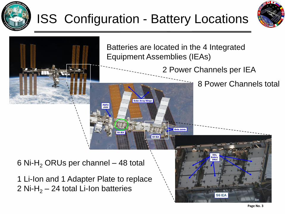
ISS Configuration - Battery Locations
2 Power Channels per IEA
Batteries are located in the 4 Integrated
Equipment Assemblies (IEAs)
6 Ni-H2 ORUs per channel – 48 total
1 Li-Ion and 1 Adapter Plate to replace
2 Ni-H2 – 24 total Li-Ion batteries
8 Power Channels total

Page No. 4
ISS Configuration - EPS Schematic
Note: 2-Battery ORUs will be
replaced by 1 Li-Ion Battery
and an Adapter Plate
Solar Array
Beta Gimbal
MBSU
Alpha Gimbal
DDCU
Shunt Unit
DDCU
Controller
Coolant
Pump
Output Power
Battery(2 ORUs)
BCDU BCDU
Battery(2 ORUs)
BCDU
Battery(2 ORUs)
Housekeeping
& Payloads
DCSU
EPS:: Electric Power System
BCDU: Battery Charge / Discharge Unit
DCSU: DC Switching Unit
DDCU: DC-to-DC Converter Unit
MBSU: Main Bus Switching Units
Electrical Power Channel – 1 of 8

Page No. 5
ISS Upgrade to Li-Ion
Ni-H2 (76 cells in series)
Li-Ion (30 cells in series)
BCDU Li-Ion
Adapter
Plate
Data
Cable
BIU
BCDU Ni-H2
Battery A
Battery B
Ni-H2
Cells
Ni-H2
Cells
BCDU: Battery Charge / Discharge Unit
BIU: Battery Interface Unit
BSCCM: Battery Signal Conditioning and Control Module
Battery
BSCCM
BSCCM
+
-
Main
Power
Path
Commands
& Data
Commands
& Data
+
-
Main
Power
Path
Commands
& Data
Commands
& Data
ExistingExisting New
Li-Ion
Cells
Page No. 6
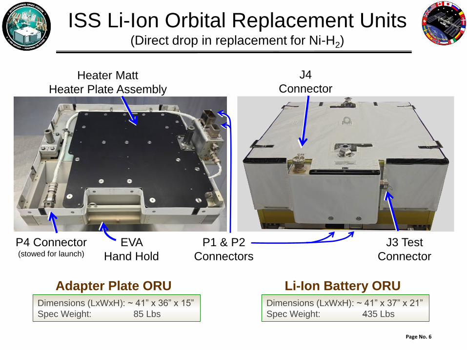
ISS Li-Ion Orbital Replacement Units(Direct drop in replacement for Ni-H2)
Adapter Plate ORU Li-Ion Battery ORU
Dimensions (LxWxH): ~ 41” x 37” x 21”
Spec Weight: 435 Lbs
Dimensions (LxWxH): ~ 41” x 36” x 15”
Spec Weight: 85 Lbs
Heater Matt
Heater Plate Assembly
EVA
Hand Hold
P1 & P2
Connectors
P4 Connector(stowed for launch)
J3 Test
Connector
J4
Connector
Page No. 7
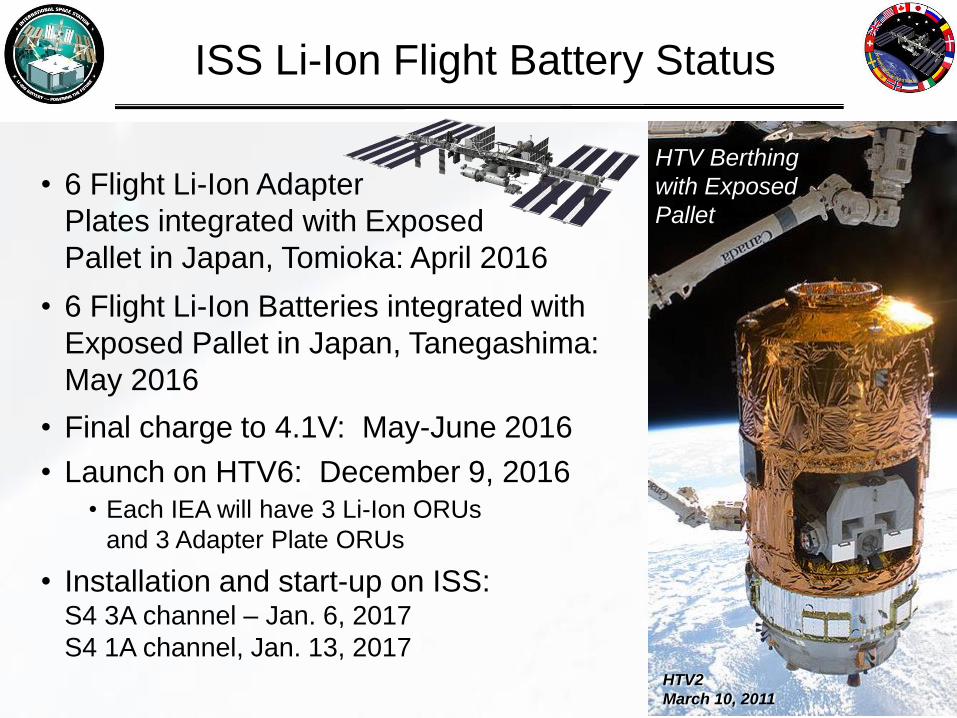
ISS Li-Ion Flight Battery Status
• 6 Flight Li-Ion Adapter
Plates integrated with Exposed
Pallet in Japan, Tomioka: April 2016
• 6 Flight Li-Ion Batteries integrated with
Exposed Pallet in Japan, Tanegashima:
May 2016
• Final charge to 4.1V: May-June 2016
• Launch on HTV6: December 9, 2016• Each IEA will have 3 Li-Ion ORUs
and 3 Adapter Plate ORUs
• Installation and start-up on ISS: S4 3A channel – Jan. 6, 2017
S4 1A channel, Jan. 13, 2017HTV2
March 10, 2011
HTV Berthing
with Exposed
Pallet

Page No. 8
Docking of HTV6 to ISS
HTV Approach to ISS
• Launch Date December 9, 2016
• EP (Exposed Pallet) Captured and
Attached to POA 12/13/2016
• Installation and startup (next slides)

Page No. 9
• 12/13/2016 After
docking, robotic removal
of EP with Li-Ion ORUs
Removal of Exposed Pallet
with Li-Ion ORUs

Page No. 10
• 12/13/2016 After ISS docking,
EP taken out of HTV6
• EP moved to ISS truss for
Battery installation
Moving the Li-Ion ORUs
Dextre

Page No. 11
Robotic
arm
Li-Ion
Battery
ORU
Robotic Installation of Li-Ion
Battery ORU
• S4 3A Batteries • Robotically installed
12/31–1/2/2017
• EVA and start up 1/6/2017
• S4 1A Batteries • Robotically installed
1/8–1/12/2017
• EVA and start up 1/13/2017
Robotic Arm
(Dextre)
Page No. 12
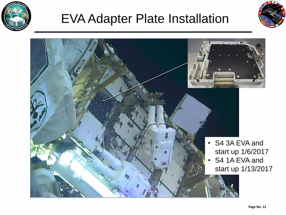
EVA Adapter Plate Installation
• S4 3A EVA and
start up 1/6/2017
• S4 1A EVA and
start up 1/13/2017

Page No. 13
• 1/22/2017 Robotic arm
moving EP with 9 Ni-H2
ORUs towards HTV6
Robotic Disposal of Exposed Pallet
with 9 Ni-H2 ORUs

Page No. 14
• 1/22/2017 Robotic arm inserting EP
with 9 Ni-H2 ORUs back into HTV6
• 1/27/2017 Undocking
• 2/5/2017 Reentry
Robotic Disposal of Exposed Pallet
with 9 Ni-H2 ORUs

Page No. 15
• Starting January 13, 2017, S4 Channels 3A and 1A are being operated using only Li-Ion Batteries
• Batteries are performing well – capacity tests at EOCV of 3.95 V• 3A: 109.3, 110.3, 110.9 Ah (see page 18)
• 1A: 114.0, 110.3, 112.3 Ah
• Minor operational observations / forward work• Battery Charge Discharge Unit advisory message – upper Voltage
Limit of 122 V exceeded (Limit to be updated to 124 V)
• Occasional switchovers of redundant heaters (A to B, B to A) (Persistence time to be updated)
• State of Charge calculation to be updated to increase accuracy
• Adjustments to Charge Profile to be evaluated
• 17 of 27 Li-Ion batteries have been built and delivered• 6 on orbit, 11 in cold storage at KSC
• 16 of 25 Adapter Plates have been built and delivered• 6 on orbit, 10 in storage at KSC
• Future Launches • Next Lithium-Ion Battery launch on HTV7, NET Feb. 2018
• Subsequent launches on HTV8- 2019, HTV9- 2020
Li-Ion Battery Status

Page No. 16
ISS Li-Ion Charge Control and Cycling
Charge Current ProfileHighest of the Cell Terminal
Voltages
Charge Current
Point 1 EOCV + 19mV 55Point 2 EOCV + 19mV 49Point 3 EOCV + 18mV 44Point 4 EOCV + 17mV 39Point 5 EOCV + 16mV 36Point 6 EOCV + 15mV 33Point 7 EOCV + 14mV 30Point 8 EOCV + 13mV 26Point 9 EOCV + 12mV 22
Point 10 EOCV + 11mV 19Point 11 EOCV + 10mV 16Point 12 EOCV + 9mV 13Point 13 EOCV + 8mV 10Point 14 EOCV + 7mV 7Point 15 EOCV + 6mV 4Point 16 not applicable 1 Data for Battery Channel 3A after ~30 days operation
Nominal On-orbit Current and Cell Voltages
Nominal On-orbit Cell Temperatures
4.1
4.0
3.9
21
17
19
Cell
Voltages
ORU
Current
• Li-Ion charge current profileis based on cell voltages
• Cell bypass/balancingat EOCV every orbit
• EOCV ground command-able

Page No. 17
ISS Li-Ion Charge Control and Cycling
ORU Voltage
Ce
ll V
olt
ag
es
(V
olt
s)
OR
U V
olt
ag
e (
Vo
lts
)
OR
U C
urr
en
t (A
mp
ere
s)
4
3.8
3.6
3.4
3.2
3.2
3
ORU Current
Cell Voltages

Page No. 18
Life Test Program
• Cell Life Testing performed at Crane Lab and NASA-GRC

Page No. 19
Life Test Program
Li-Ion Battery ORU Life Testing
at Aerojet Rocketdyne Voltage
Retention Test Data
Week 16 Test error resulted
in ~ 1.15 A-Hr discharge
Chamber Temperature at 78 °F (first 21 weeks)
70 to 73 °F (week 23 on)
Elapsed Weeks
Vo
lta
ge
OngoingSeries, Life Test Apr. 2017
Week 22 Chamber Condenser failure
resulted in temperature change
Week
Ho
lid
ay
Eq
uip
men
t
un
de
r R
ep
air
,
Un
avail
ab
le

Page No. 20
ISS Li-Ion Battery Future Plans
• Data analysis for NESC (NASA Engineering & Safety
Center) Thermal runaway propagation test performed
October 2016 at the White Sands Test Facility
• Launch of remaining Li-Ion Batteries and Adapter Plates
in 2018, 2019, 2020 to provide a full complement on ISS
First six batteries (2 power channels)
operating successfully on orbit
Page No. 21
In Closing
• Questions?

Page No. 22
Backup Materials
• Installation Robotic and EVA sequence

Page No. 23
Robotic Operations
3A Robotic:(12/31/2016 – 1/3/2017)
1A Robotic:(1/8/2017 – 1/12/2017)
Shift Operation
1A Ni-H2: 5 > Z
1B Ni-H2: 6 > Y
2A Li-Ion: B > 5
2B Ni-H2: 1 > X
3A Li-Ion: A > 1
3BNi-H2:
3 > EOTP
4A Li-Ion: C > 3
4B ROST: 1/5
Initial Configuration
Final Configuration
Page No. 24
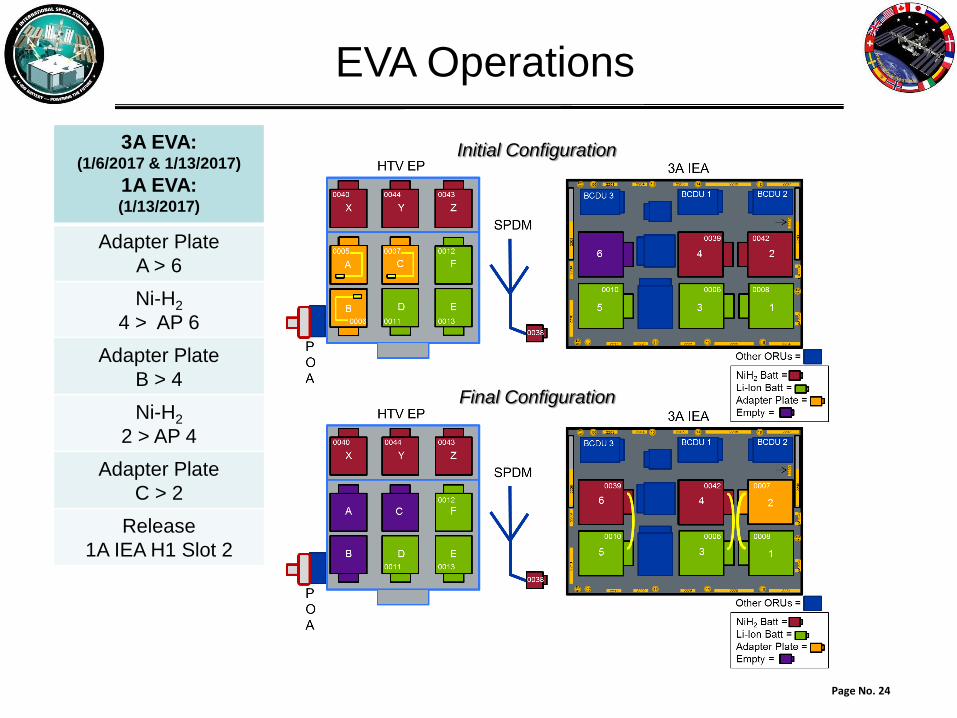
EVA Operations
3A EVA:(1/6/2017 & 1/13/2017)
1A EVA:(1/13/2017)
Adapter Plate
A > 6
Ni-H2
4 > AP 6
Adapter Plate
B > 4
Ni-H2
2 > AP 4
Adapter Plate
C > 2
Release
1A IEA H1 Slot 2
Initial Configuration
Final Configuration