Embed Size (px)
Citation preview

International Space Station (ISS) External High
Definition Camera Assembly (EHDCA)
In-Space Inspection Technology Workshop
July 16, 2014
Victor Studer
Avionic Systems Division
Avionic Systems Division
Engineering Directorate
NASA–Johnson Space Center

External High Definition Camera Overview
– Integrated as part of the ISS Communications and Tracking System
– Directional pointing provided by the Pan and Tilt Unit (PTU) of the External Television Camera Group (ETVCG).
– Receives commands and sends imagery, health and status through the External Wireless Communications (EWC) system.
– Electrical power is from sharing ISS supplied power to the Video Camera Luminaire (VCL) heaters (120VDC).
– EHDCA can be installed either IVA or during EVA.
– Control of the EHDCA is from the Mission Control Center (MCC)
– Commercial Off the Shelf (COTS) hardware based.
• International Space Station (ISS) program requested Engineering to provide an external
high definition (HD) video capability to view Earth and ISS.
CTVC
EHDC
Luminaire
ETVCG
Figure 1: ETVCG Assembly w/EHDC

EHDCA Installation Locations
• Flight units to be installed at each camera port location – CP3, CP8, CP9 and CP13
EWC Antennas
Figure 2: ISS Camera Port Locations

External High Definition Camera Overview
• EHDCA Constraints/Requirements – Weight and volume limits (< 30 lbs and limited envelope)
– EVA compatible for installation and removal.
– Power Limit <248 watts (later lowered to ~200w)
– Provide standard (NASA-STD-2818) HD Video (720P60)
– Controllable zoom lens
– Provide minimum of 2 years of operational life
– Conform to EWC wireless Ethernet based communications (802.11n, 5.2 GHz) WiFi compatible system through the ISS Joint Station LAN (JSL)
– H.264 compression with MPEG2 transport stream HD video
– Must provide high quality HD video views of ISS and Earth, inspection is not a requirement of this system
• EHDCA Goals – Provide imagery if Airlock, HTV Capture and Node 2 Nadir activities (RF coverage)
– KX/Imagery Analysis Group provided list of Desirements
• Provide ‘wide’ field of view zoom of 5o to 75o
• Provide 2 - 4 pixels/0.1 inch resolution at 267.5 feet (Camera/Lens selection) – 1280 x 720 pixel HD resolution this equates to ~ 1.2 degree Horizontal Field of View (HFOV).
• Automatic control (iris, focus, gain, white balance etc.) with manual override
• Metadata & telemetry downlink
• Three chip sensor system camera (no Bayer pattern)

EHDCA Architecture
EHDCA Integrated System Architecture
• EWC compatible radio and antennas operating in Client mode
– EWC Wireless Access Point (WAP) radio couldn’t be used
– New radio had to be qualified for EHDC (Boeing provided)
• Based on Moxa AWK-4131 radio
• Ruggedized and updated firmware to increase power output over standard model
– Circular polarized, wide beam, small, 5.3 GHz antenna required
• Camera & Lens selection trade study
– Ethernet based control was significant factor in trade
– 720P60 high definition video output required
– Size, Weight and Power (SWAP) limitations
• Controller for system control and status.
• Video Compression Encoder – Selected H.264 encoder recently certified for ISS
internal use
• Ethernet Switch – Internal Ethernet interconnections.

EHDCA Architecture
• EWC drove need for an Ethernet based integrated video and communications
architecture
Figure 3 – EHDC Ethernet Based Architecture

EHDCA Installation Locations
Figure 4 – Simplified CAD model of ETVCG and EHDC Locations
CP8
CP9
CP3
CP13
US Lab EWC Antenna

EHDC Architecture – Wireless Antenna Coverage
Key to success of EHDC depends entirely on our RF coverage in conjunction with EWC
• External Wireless Communications (EWC) Background
– EWC Myers antenna test data shows irregular coverage.
– EHDC camera locations show positive signal margins for 10 Mbps communications - just.
– EWC antennas are linearly polarized, EHDC antennas had to be circularly polarized (-3dB loss)
Figure 5 – EWC RF
Coverage Analysis

EHDC Architecture – Wireless Antenna Coverage
• EHDC cameras will have nearly spherical imagery coverage thanks to the
ETVCG’s Pan and Tilt Unit.
• RF coverage is limited by mounted antennas which will move with the EHDC.
– Antenna selection based on trade study and test of commercial antennas – best antenna gain limited to
~ +/– 30 degrees off axis, limited gain below.
– Unique ground plane designed to improved overall coverage.
– Antennas must be circularly polarized to work with EWC linearly polarized antennas.
Figure 6 – Various Pan and Tilt Configurations

EHDC Architecture – Wireless Antenna Coverage
• EHDC Antenna selection/design – Antenna selection restricted to available COTS
– Selected Tecom Cavity-Backed Spiral – Nominal 70 degree beam.
– Beam shape depends on associated ground plane.
– Significant study, design, analysis and testing effort went into the final ground plane geometry.
• Optimized gain and axial ratio
Figure 7: Tecom Antenna
Figure 8: Final Ground Plane Geometry Figure 9: Ground Plane Design RF Coverage

• EHDC housing structure effects on antenna RF Coverage.
– Upper Antenna mounted to flat EHDC upper lid
EHDC Architecture – Wireless Antenna Coverage
-180-150-120 -90 -60 -30 0 30 60 90 120 150 180
-180-150-120 -90 -60 -30 0 30 60 90 120 150 180
0
20
40
60
80
100
120
140
160
180
0
20
40
60
80
100
120
140
160
180
[Degrees]
[D
egr
ees]
-11.0 [dBic]
-10.0 [dBic]
-9.00 [dBic]
-8.00 [dBic]
-7.00 [dBic]
-6.00 [dBic]
-5.00 [dBic]
-4.00 [dBic]
-3.00 [dBic]
-2.00 [dBic]
-1.00 [dBic]
0.00 [dBic]
1.00 [dBic]
2.00 [dBic]
3.00 [dBic]
4.00 [dBic]
5.00 [dBic]
6.00 [dBic]
7.00 [dBic]
8.00 [dBic]
Figure 12 – Upper Antenna 3D Countour Plot Figure 11 – Upper Antenna Measured RHCP Gain
Figure 10 – Upper
Antenna Mount

• EHDC housing structure effects on antenna RF Coverage
– EHDC Lower antenna mounted to irregular lower housing structure
EHDC Architecture – Wireless Antenna Coverage
-180-150-120 -90 -60 -30 0 30 60 90 120 150 180
-180-150-120 -90 -60 -30 0 30 60 90 120 150 180
0
20
40
60
80
100
120
140
160
180
0
20
40
60
80
100
120
140
160
180
[Degrees]
[D
egre
es]
-11.0 [dBic]
-10.0 [dBic]
-9.00 [dBic]
-8.00 [dBic]
-7.00 [dBic]
-6.00 [dBic]
-5.00 [dBic]
-4.00 [dBic]
-3.00 [dBic]
-2.00 [dBic]
-1.00 [dBic]
0.00 [dBic]
1.00 [dBic]
2.00 [dBic]
3.00 [dBic]
4.00 [dBic]
5.00 [dBic]
6.00 [dBic]
7.00 [dBic]
8.00 [dBic]
Figure 13 – Lower
Housing Antenna Mount
Figure 14 – Lower Housing Antenna Measured Gain
Figure 15 – Lower Antenna 3D Countour Plot

Camera/Lens Trade Study Results
• Extensive market trade study, camera evaluation and tests performed
– Broadcast quality 3 chip box cameras and associated lenses exceed limits
– Smaller ‘Professional’ 3 chip cameras underperformed and/or failed radiation testing
– Inspection/security cameras not compatible with broadcast standards
– DSLR camera/lenses at upper SWAP limit but none provided adequate external control capabilities
• Nikon D4 camera undergoing testing as the next EVA camera with extensive USB control
interface, Ethernet and HDMI interfaces available but with limited functionality
– Long history of good working relationship with Nikon
– Nikon believed camera firmware updates could be made to meet our Ethernet control and
HDMI output requirements
– All controls required for camera operation could be controlled remotely
– Radiation performance acceptable
» ~95 percent of damaged pixels anneal with time
» Expected life due to permanent damage should exceed 2 – 4 year planned EHDC
operational life
• Other DSLR cameras required manual switch activations for basic operations
• External zoom lens drive would have to be added for any DSLR
• DSLR cameras have known video performance deficiencies and few fine adjustments normally
found on professional video cameras
• DSLR’s are used extensively for television and cinema productions

EHDC Camera
• Nikon D4 DSLR with 28-300mm lens & 2X teleconverter selected as EHDC camera.
– Selection based on criteria established by user community, ISS program and engineering
– Final selection made after ‘Camera Summit’ with demonstrations of top candidate cameras
– Nikon provided firmware updates solved original limitations.
– 1280 x 720 progressive video mode uses slightly less than full image sensor
• Video pixels integrated across 9 Bayer pattern sensor pixels
– 16.2MP sensor, still camera limited to 13.6 MP (4928 x 2768 pixel) in 16:9 movie mode
– Auto and manual focus provided through EHDC control system
– Sensitivity ISO 100-12800 range plus extended EV settings (-.3 & +4 EV) giving ISO 50 – 204800
– Control of all camera functions is through Ethernet port allowing full remote control
– Camera provides LiveView mode with low data rate imagery provided through Ethernet port
• Allows operators to view still or video imagery prior to downlink
• Expanded view up to full resolution of sensor
• Downlink video imagery is same as low data rate LiveView
– External stepper motor zoom lens drive controlled through EHDC controller
• 56 – 600 mm zoom lens gives ~ 3.4 – 36 degree horizontal field of view
• Focus drive controlled through camera
• EHDC Control software developed for MCC operators - Allows full camera control, video and still picture
downlinks.
- Provides EHDC system telemetry including EWC
received signal strength
Figure 16: D4 Camera w/Lens

EHDC Architecture
• Remaining EHDC Components
– Controller – Off the shelf ASD Modular Instrumentation design
• Power control –
– Allows operator control to reset power to components in event of detected SEU
– Controls standby mode (camera & encoder turned off)
• Status telemetry (temperature, pressure, currents)
• Watchdog timer
• Control camera zoom lens function
– Video Encoder
• Visionary Solutions Incorporated (VSI)
AVN443HD Encoder
• HD H.264 encoding bit rate range 5 – 20 Mbps
• Nominally set to 8 Mbps encoding
• Provides standard MPEG 2 Transport Stream
– Power Supply – 120 V power is always on
• Power shared with Luminaire heater power
• Primary power supply 120 VDC to 24 VDC
• Secondary board provides separate power supplies
for each component
– Heaters
• Thermostat controlled
• 120 VDC direct from input power Figure 17: EHDC Block Diagram
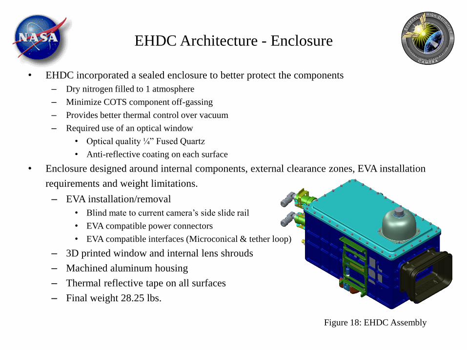
EHDC Architecture - Enclosure
• EHDC incorporated a sealed enclosure to better protect the components
– Dry nitrogen filled to 1 atmosphere
– Minimize COTS component off-gassing
– Provides better thermal control over vacuum
– Required use of an optical window
• Optical quality ¼” Fused Quartz
• Anti-reflective coating on each surface
• Enclosure designed around internal components, external clearance zones, EVA installation
requirements and weight limitations.
– EVA installation/removal
• Blind mate to current camera’s side slide rail
• EVA compatible power connectors
• EVA compatible interfaces (Microconical & tether loop)
– 3D printed window and internal lens shrouds
– Machined aluminum housing
– Thermal reflective tape on all surfaces
– Final weight 28.25 lbs.
Figure 18: EHDC Assembly

EHDC Internal Design
• Internal Packaging
– Camera, lens, zoom lens motor drive, power supply, controller mounted on ‘doghouse’
Nikon D4
Camera
Kenko Teleplus MC7 AF
2.0 DGX Doubler
f/3.5-5.6 ED AF-S
Nikkor 28-300 VR
Lens
Camera and Lens Mount
SDG33124452-001
AL ALY 6061
Figure 19: EHDC Camera Mount

EHDC Internal Design
• Internal Packaging
– Doghouse assembly, encoder, switch, radio, antennas, cabling incorporated in overall EHDC assembly
Figure 20: EHDC Assembly

EHDC Performance
• End to end camera video/encoder performance
– Video resolution measured at Usable and Limiting values
• Worse case (600 mm telephoto) usable resolution ~ 600 TV Lines/picture height
• Limiting resolution ~ 690 TV Lines/picture height
– Still imagery resolution > 2000 lines
– Optical window has very little effect on image resolution
• Small degradation at 600 mm, effect is greater in still imagery mode
• Not noticeable in video mode
• Low light level operation
– Required to work with ISS ETVCG mounted Luminaire – Specified to provide 3 foot-candle at 60
feet
– Video low light performance limited by 1/60 sec frame rate – ISO 12800 +4EV creates grainy, noisy
video image at 3fc and lower
– Still image capture at longer integration time and optimal settings operates well below 3 fc

EHDC Performance
• Low light level still imagery
Figure 21 - 32 Lux (~3fc) Lab Image Figure 22 - 11 Lux (~1fc) Lab Image

Flight and Installation Schedule
• 2 ORUs and Cables on Orb-4
– SpX7 BU flight
– Support EVA D, Install CP8 & CP13 (April, 2015)
• One unit on SpX7
– No BU Flight
– Support EVA E-1 (June, 2015)
• One unit on SpX8
– Orb-5 BU flight
– Support EVA E-2 (July, 2015)