Embed Size (px)
Citation preview

International Laser Ranging Service
Analysis Working Group
Minutes of AWG Meeting Vienna, Austria
April 14, 2007
Erricos C. Pavlis JCET/UMBC – NASA Goddard
Vicenza Luceri e-GEOS, S.p.a. - ASI
AWG Coordinators
JCET-ISG-2007-02
Joint Center for Earth Systems Technology
University of Maryland Baltimore County
Baltimore, Maryland, 21250
May 20, 2007

JCET-ISG-2007-02
ILRS AWG Page 1 5/20/07
AWG Spring meeting – TU Wien, April 14, 2007
Starting at: 9:00 am SEM124
Leonhard Euler was born in Basel, Switzerland, called the "Mozart of Mathematics," Euler published more than 800 papers of pure and applied mathematics before his death in 1783 (Sunday, April 15, 2007, marked the 300th anniversary of his birth).

JCET-ISG-2007-02
ILRS AWG Page 2 5/20/07
Opening – Agenda review and adjustment & announcements
Old topics:
Benchmark project: status
GA : completed successfully, official ILRS AC again.
GRGS : A problem exists in the submitted orbit for the benchmark. After orbit comparisons with BKG, the problem has been isolated in the transformation from the inertial to the terrestrial reference frame. GRGS will send to Pavlis the inertial state vectors and the transformation matrices, to be checked within may 15th (or two weeks after receiving them). After that date, they will start to submit the weekly files to the CC for preliminary tests.
NCL : submitted case is being examined now.

JCET-ISG-2007-02
ILRS AWG Page 3 5/20/07
Operational product "positioning + earth orientation"
ITRF2005 & ITRF200X: ILRS 1983-1992 reports on analysis progress
o ASI - time series 1983-1992 delivered. Plots with EOP and SSC comparison w.r.t. EOPC04 and ITRF2000 respectively. time series 1993-2006 delivered.
o BKG - None
o DGFI - Time series 1981-1992 delivered. Differences in the estimated orbits when using NASA and DGFI normal points. Time series 1993-2006 delivered. Check of DOGS versions undergoing, DGFI seems to be worse that others in estimation of the station UP component.
o GA – Frank Lemoine reported for Ramesh that: time series 1983-1992 in processing and time series 1992-2006 delivered.
o GFZ - Time series pre-1993 not delivered. Reported problems with the use of the normal points, probably due to the flags for the tropospheric correction. Joint effort DGFI-GFZ to fix the problem. Time series 1993-2006 delivered.
o JCET – Reprocessed 1993-2007 time series submitted. Historical data analysis in 15—day arcs completed and submitted for the period 1976-1993. 5-day EOP solved for up until mid-1979, followed with 3-day EOP after the SINEX with date 790715.
o NSGF - Time series 1983-1992 delivered. Plots on the height time series for a few stations, reasonably good results. Stanford corrections to be included. Time series 1993-2006 delivered.
o GRGS - Plots on the high correlation between range biases and UP component were shown. The estimation of biases over long period decreases the correlation. A website exists with the database of the official ILRS solutions at:
http://www.obs-azur.fr/gemini/donnees/index.html. Presentation on the status of the MEO telescope (1 year for the first observations to geodetic satellite and the moon) and the FTLRS laboratory.
operational product: ILRS-A/B technique issues, quality/refinement of products (e.g. weekly geocenter)

JCET-ISG-2007-02
ILRS AWG Page 4 5/20/07
o JCET – presentation of the QC/QA site and the new additions in terms of weekly reports for each AC/CC to help monitor the quality of the submitted products. Follow the link:
http://geodesy.jcet.umbc.edu/ILRS_QCQA
Operational product enhancements – several suggestions:
o Generation of a SLR-only TRF ala IGS00, etc.
o Investigate the benefits of implementing atmospheric signals in SLR
Pavlis suggests the application of the atmospheric loading and atmospheric gravity to the analysis for the ILRS products. The adherence to the IERS standards will be checked. A test on a couple of months will be done. Pavlis will send an e-mail with the months to be reprocessed.
o Adoption of an ITRF2000 replacement timetable (ITRF2005SLR?)
Adoption of a new ITRF. ITRF2000 and ITRF2005 are not suitable for SLR products and thus a new ITRF will be prepared using the rescaled ITRF2005, ITRF2000 roto-translated to ITRF2005 and the new stations in the ITRF2005 frame. The new ITRF will be named SLR05 and will be available within mid-may (Pavlis and Luceri).
o Generation of daily EOP ala NEOS:
Pavlis suggests the production of daily solutions. It is accepted to generate each day a 7 day arc solution with the same characteristic of the actual products. The time delay between the solution generation and the last analyzed data could be reduced after a check of the data delivery times (HTSC). The new timeline will be defined before the next meeting in Perugia.
o Generation of a “geocenter” product:
Luceri had suggested to deliver the weekly similarity parameters as official ILRS geocenter. It is decided to deliver the geocenter, in SINEX format, together with the new combined time series, after modelling update and Stanford corrections fixed.

JCET-ISG-2007-02
ILRS AWG Page 5 5/20/07
System bias studies (present and future):
Stanford ET status report (Appleby & Gibbs) Presentation of the work on the Stanford calibration. Center of mass correction. List of
corrections for most sites, plots of post fit range residuals as a function of returns per
normal points.
Appleby had circulated in 2006 December a table of corrections to be applied to range
data from stations using Stanford counters. Most of the corrections were estimates
(probable uncertainty ~5mm) based on characteristics of the Stanfords in use at
Herstmonceux. Corrections of up to 10 or 15mm in range were indicated by this work. It
is planned to examine at Herstmonceux as many as the operational Stanford counters as
possible, in order to improve the estimated range errors due to the devices.
Luceri reported that the Stanford corrections have introduced an artefact in the series. The
UP component of the stations, affected by those corrections, is smaller and, since some of
them are core stations, the SLR scale is shortened. The difference w.r.t. ITRF2000 and
ITRF2005 is increased by 4 mm. Some stations had a jump in the range residuals caused
by the introduction of the Stanford counter corrections and they seem to be larger after
applying the corrections. This evidence suggests an incorrect sign in the adopted
corrections.
Koenig showed results of the new series using the new standards: M-P model and
Stanford corrections. His results indicated a general deterioration of his solutions.
After discussion on the adopted Stanford corrections, it was agreed that:
- Appleby will check and report back on the corrections for Herstmonceux and for the
estimates for the other Stations.
- No Stanford correction will be applied to other stations. Gurtner underlined that
corrections based on assumptions can be dangerous. ACs will remove those
corrections from their modelling starting from the first week of May.
- A systematic analysis of the biases to be applied to the stations will be done and a list
of biases will be produced. The new re-analysis will apply those corrections. (Pilot
project?)
CoM corrections for all targets, sites and time periods/configurations
Considering that 6.4 mm correspond to ~1 ppb in scale change of the TRF, CoM
corrections are becoming a major error source for SLR. The table that Appleby has
generated for the LAGEOS CoM corrections will be examined to decide which “fixed”
values should be adopted for each site, based on the range of values provided in that table
(sometimes up to 10 mm).
Core site bias characterization in view of ILRS’ mm-SLR goal
A study of the Eastbourne list will be done in order to revise the sites for which biases
will be allowed to solve-for or to model a priori. Target date for discussion: Perugia

JCET-ISG-2007-02
ILRS AWG Page 6 5/20/07
Quality assessment of new SLR systems/sites (H. Müller)
The assessment of new stations will be based on: data quality, reliability, stability. The
new data will be processed by two designared ACs that will generate range biases for all
passes and will compute weekly coordinates. Close coordination and contact between the
new site and the two ACs will be a prerequisite.
Station performance card (ASI CC & DGFI CC)
The original idea of generating a “station performance card” based on the official weekly
ILRS products is still not settled. The two CCs need to coordinate their activities and to
generate reports for the sites that seem to under-perform on a given week or have an
abrupt change in their coordinates or bias estimates.
Dunn reported new web pages on products and station performance charts at the ILRS
website. He also discussed and explained the Simosato height changes and their
explanation based on system changes verified through discussions with the local team.
Precise orbital product project (SP3c)
Status report (ECP & Müller and CC reps)
Pavlis showed the newly adopted (multi-technique) table with the official satellite codes
to be used in the generation of SP3c files. The exchange of test SP3c files will be done
prior to the Perugia meeting.
Project "harmonization" Status report (Mareyen)
None
NEW topics:
GGOS and ILRS, establishing a closer tie with GGOS and maintaining a “live” link to GGOS, providing input for the studies and support documents that GGOS requires
Pavlis suggested that the AWG members should start to interact with GGOS more closely
and monitor the areas of GGOS interests central to SLR. Suggested that AWG members
attend the various GGOS meetings that were planned during the EGU week.
Independent validation of SLR height variations and bias estimates with a routine AG survey of the core sites over time (1 to 4 times per year - baseline, once a month - goal)
Pavlis suggested the use of absolute gravimetry in the form frequent site surveys at SLR
sites in order to place bounds in the SLR biases. ASI and NSGF possess AGs and could
make them available in principle. NSGF reported that they are running their system on-
site now.

JCET-ISG-2007-02
ILRS AWG Page 7 5/20/07
Report of the new WG on the evaluation/validation effort for site-ties between SLR and other techniques (GB & CL)
No major progress. A team has been formed, but the Networks & Engineering Group has
not submitted a candidate yet. Julie Horvath/HTSI was suggested as a good candidate and
Pavlis suggested also Detlef Angermann/DGFI.
Generation of “clean” observational data set with known biases applied? (for use by POD groups)
Pavlis suggested the formation of a “clean” set of observations in the form of validated
biases and data rejections to be made available to the wider SLR user community. The
file that Müller is generating can perform this function if it is maintained and extended to
past years. Action on this was postponed until we have clarified site biases further.
Miscellanea:
SLR tracking network (status, weekend effect) – no news
consistency of QC reports (ILRS CB) – no news
documentation of analysis (ECP & CL) -- DONE
special issue Journal of Geodesy (Noomen) – Ron is working on it
other topics ???
Next meeting(s):
2-day meeting at Perugia (IUGG/IAG, July) ? The AWG tentatively agreed on a 2-day workshop in Perugia, during the IAG/IUGG.
NOTE ADDED 07/05/08: The workshop length was later revised to 1-day with a much
more focused agenda on urgent topics and an attempt to ensure that all open issues are
on-track, keeping in mind the need for final results for the December workshop.
1-day meeting at Grasse Tech. Workshop (September)? The 1-day workshop during the Grasse meeting in September will serve as a final review
and planning meeting for the program that the AWG will present at the December MTW.
N-day IAG Services’ workshop prior to Fall AGU (San Francisco, December ‘07) Pavlis reported the invitation/request from Rotacher for participation in a Multi-
Technique Workshop (MTW), to discuss issues, practices and common topics associated
with the analysis of space geodetic data.

JCET-ISG-2007-02
ILRS AWG Page 8 5/20/07
Action items
Open action items from past AWG meetings
ACs prepare for new format SLR data (see attachment)
ACs include conversion of orbit solutions into SP3c format (step-size 2
minutes for LAGEOS; 15 minutes for Etalon)
AWG re-assess AWG core stations status + general ILRS classification
AWG make overview of station activities 1993-present, based on
eccentricity file and “pos+eop” info
CCs prepare for combination of SP3c files
Mareyen develop 2-day analysts get-together in Frankfurt(???)
Mareyen investigate reasons for degradation of NKG(???) contribution to
operational product
Müller (Horst), Pavlis exchange and compare orbits in SP3c format
Müller develop slr_discontinuities file further (1992-2006)
Müller (Jürgen) develop validation plan for (new) LLR stations
Noomen, Pearlman, Gurtner homogenization of QC reports
Noomen get letter expressing general support for ILRS activities from
IERS chairman
Noomen, Luceri, Gurtner develop report with pos+eop use for stations and managers
Noomen organize guest editorial board for JoG special issue
Noomen check IERS procedure for station documentation after
earthquakes and such
Noomen get Delft QC procedure running again
Pearlman remind Simosato to become IGS station
New action items
Pavlis dataset for the test on the models of atmospheric loading and
gravity
Pavlis, Luceri new ITRF for SLR analysis
HTSI check of the station data delivery time
GRGS inertial state vectors and transformation matrices to Pavlis
Pavlis check of the GRGS orbits and transformation matrices
Appleby check the Stanford corrections for Herstmonceux
ACs remove Stanford corrections from the routine weekly analysis
Pavlis Luceri pilot project for the generation of a bias list, etc.
CCs start combination from pre-1993 time series, after GFZ
submission
ACs and CCs work on generating daily submission of weekly solutions
Closing comments
See you all in Perugia.

JCET-ISG-2007-02
ILRS AWG Page 9 5/20/07
Participants Zuheir Altamimi [email protected] Graham Appleby [email protected] Giuseppe Bianco [email protected] Florent Deleflie [email protected] Pierre Exertier [email protected] Peter Dunn [email protected] Richard Gross [email protected] Werner Gurtner [email protected]
Julie Horvath [email protected]
Gary Johnston [email protected] Rainer Kelm [email protected] Rolf König [email protected] Frank Lemoine [email protected] Vincenza Luceri [email protected] Maria Mareyen [email protected] Horst Müller [email protected] Jürgen Müller [email protected] Carey Noll [email protected] Erricos C. Pavlis [email protected] Mike Pearlman [email protected] Claudia Urschl [email protected]
Scott Wetzel [email protected] Yaroslav Yatskiv [email protected]
ANNEX
Presentations at AWG meeting of 07/04/14
ASI_awg_07_comb.ppt ASI_ILRS_AWG_Wien_0407_post93.ppt ASI_ILRS_AWG_Wien_0407_pre93.ppt DGFI_ILRS_awg_wien07_2.ppt DGFI_ILRS_awg_wien07_1.ppt DGFI_ilrs_awg_vienna_2007.pdf DUNN_Yarg_lclt_rng.pdf DUNN_station_front_page.pdf DUNN_official_products.pdf DUNN_2007_qrt1.pdf GFZ_egu_070417_rk.pdf GRGS_AWG_Wien_2007.ppt ITRS_ILRS-AWG-vienna-April-14-2007.ppt Lageos_com.xls NSGF_AWG_CoM.ppt NSGF_Stanford_calib.ppt NSGF_back_soln.ppt
JCET-ISG-2007-02
ILRS AWG Page 10 5/20/07
New SLR data format
crd_v0.26.pdf
SP3c Satellite Code list
ALL_MISSIONS_TABLE_070201.pdf
Eastbourne accords bias list (discussed briefly but not shown)
Bias List 2 Update 070414 .pdf

G. Bianco, C. Sciarretta, V. Luceri
ILRS AWG Meeting, April 2007, Wien, Austria
Status of ILRSA Status of ILRSA WeeklyWeekly SolutionSolution
3d Sites WRMS w.r.t. ITRF2000 (31/12/05 - 24/03/07)
0
10
20
30
40
50
60
70
53700,00
53760,00
53820,00
53880,00
53940,00
54000,00
54060,00
54120,00
54180,00
mm
WRMS
WRMS_CORE
ILRSA consistency w.r.t. ITRF2000
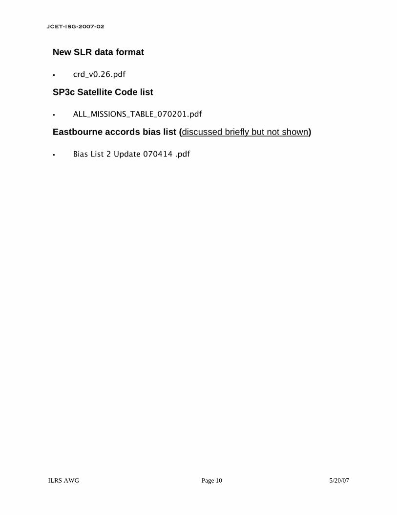
Hereafter the plot showing the 3d differences of ILRSA weeklysolutions for the period 31/12/05 – 24/03/07 is shown.
The combined solutions include solutions from asi, bkg, dgfi, gfz,jcet, nsgf as provided weekly.
Only five weeks have been reprocessed for the period: they areavailable as “v2” in the archives.
The agreement for the Core Sites is at one cm level; from week060107, different corrections have been applied: they turn into anincreased 3d WRMS of the analysed differences.

ILRSA consistency w.r.t. ITRF2000
The single solution behavior (Core Sites) is similar, showing the sametrend from 060107 onwards
3d Sites WRMS w.r.t. ITRF2000 (31/12/05 - 24/03/07)
0
10
20
30
40
50
60
70
53700,00
53760,00
53820,00
53880,00
53940,00
54000,00
54060,00
54120,00
54180,00
mm
ASI
BKG
DGFI
GFZ
JCET
NSGF
ASI 11.9
BKG 11.1
DGFI 12.4
GFZ 12.1
JCET 10.0
NSGF 14.2
On the right, the average 3d WRMS (mm) foreach solution (Core Sites) is reported
ILRSA internal consistency
3d Sites WRMS w.r.t. ILRSA (31/12/05 - 24/03/07)
0
10
20
30
40
50
60
70
53700,00
53760,00
53820,00
53880,00
53940,00
54000,00
54060,00
54120,00
54180,00
mm
ASI
BKG
DGFI
GFZ
JCET
NSGF
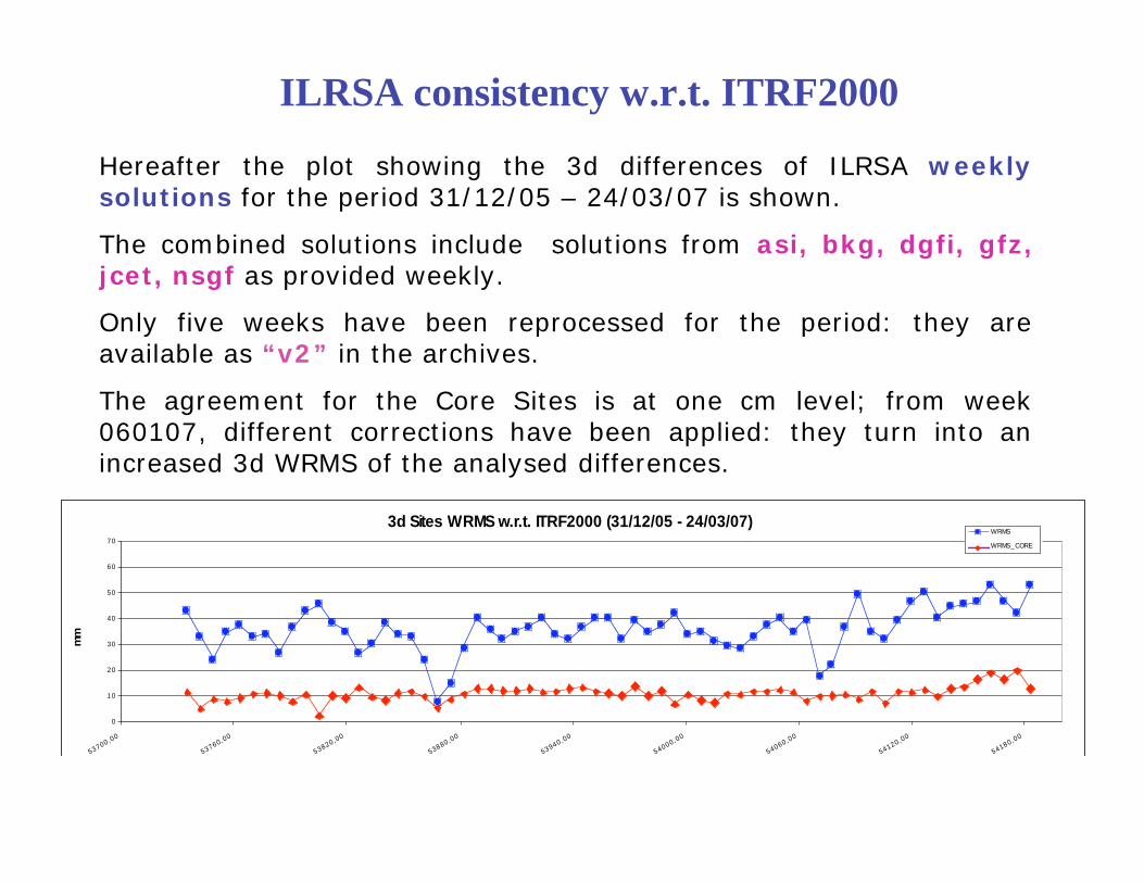
Moreover, the agreement of each solution w.r.t. the combined ILRSAis shown (all sites)
ASI 5.5
BKG 7.5
DGFI 10.8
GFZ 7.0
JCET 5.8
NSGF 11.3
On the right, the average 3d WRMS (mm) foreach solution w.r.t. ILRSA (all sites) isreported; ASI and JCET agree to ILRSA at 5mm level, DGFI and NSGF agree at 1 cmlevel.

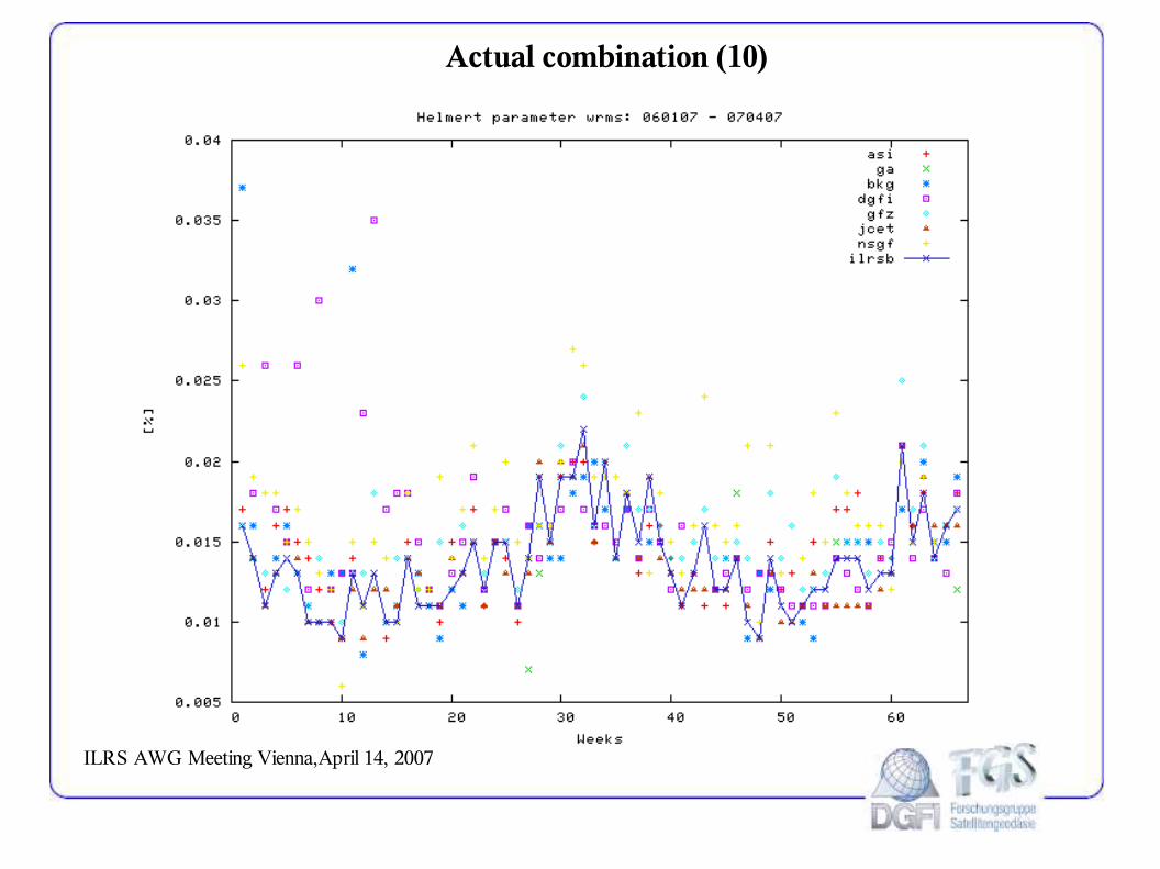
ILRSA Helmert Parameters
The usual plot for the Helmert Translation is shown for the analysedperiod (31/12/05-24/03/07); some different behaviors can bedetected, again, after week 060107 (mjd>54106): Tz seems to becloser to 0, a slightly variability seems to appear in Tx and Ty; moredata in the time series are needed!!
Helmert Translations w.r.t. ITRF2000 (31/12/05 - 24/03/07)
-30
-20
-10
0
10
20
30
40
50
53700,00
53760,00
53820,00
53880,00
53940,00
54000,00
54060,00
54120,00
54180,00
mm
Tx
Ty
Tz

Helmert Scale Factor w.r.t. ITRF2000 (31/12/05 - 24/03/07)
-5
-4
-3
-2
-1
0
1
2
3
4
5
5370
0,00
5376
0,00
5382
0,00
5388
0,00
5394
0,00
5400
0,00
5406
0,00
5412
0,00
5418
0,00
ppb
Sc ale Fac tor
ILRSA Helmert Parameters
The usual plot for the Scale Factor is shown for the analysed period(31/12/05-24/03/07); again, after week 060107 (mjd>54106): agreater variability and a different trend seems to appear

ILRSA EOP
EOP w.r.t. USNO "finals.daily" - weekly RMS (31/12/05 - 24/03/07)
0
100
200
300
400
500
600
700
53700,00
53760,00
53820,00
53880,00
53940,00
54000,00
54060,00
54120,00
54180,00
Xp
Yp
LOD
Above, the RMS values of the differences between ILRSA and USNO“finals.daily” (as used in the weekly report) are plotted; units are μas(xp, yp) and μs (lod).
In the next slide the differences are reported in terms of offset andSTD.

ILRSA EOP EOP w.r.t. USNO "finals.daily" - weekly offset (31/12/05 - 24/03/07)
-700
-600
-500
-400
-300
-200
-100
0
100
200
300
400
500
600
700
53700,00
53760,00
53820,00
53880,00
53940,00
54000,00
54060,00
54120,00
54180,00
Xp
Yp
LOD
EOP w.r.t. USNO "finals.daily" - weekly STD (31/12/05 - 24/03/07)
0
100
200
300
400
500
600
700
53700,00
53760,00
53820,00
53880,00
53940,00
54000,00
54060,00
54120,00
54180,00
Xp
Yp
LOD

ILRSA operational solution for IERS EOP
IERS provided values (2006 ->) for operational series compared to EOP C04

ILRSA Status Summary
• The operational production of ILRSA weekly solutions continuesregularly
• 6 ACs have been contributing regularly since 2006.0
• All the ACs individual solutions share a common good level ofquality
• GA AC has just started (week 070407) the regular contributionafter having successfully passed the benchmark test
• ITRF2000 is still adopted in the combination solutions productionand reported in the summary files
• ILRS combined solutions are used regularly in the production ofEOPC04 series; IERS allows a continuous monitoring of the quality ofour ILRS solution and of its performance w.r.t. to the othercontributors

G.G. Bianco - Bianco - Agenzia Spaziale ItalianaAgenzia Spaziale Italiana
V. V. LuceriLuceri –– e-GEOSe-GEOS S.p.A. S.p.A.
ILRS AWG Meeting, 14 April 2007, Wien
ASI ASI operationaloperational productsproducts: 1993-2007 : 1993-2007 seriesseries
((versionversion 6) 6)

Core stations
11001S002 7839 Graz 96:268:55735
40451M105 7105 Greenbelt 93:018:15434
13212S001 7840 Herstmonceux 92:362:04637
40442M006 7080 McDonald 93:011:47264
40497M001 7110 Monument Peak 93:004:12732
14201S018 8834 Wettzell 93:012:46468
50107M001 7090 Yarragadee 92:362:54751
14001S007 7810 Zimmerwald new 96:353:62813
10002S002 7845 Grasse 97:327:55006 04:265:02443
40445M001 7210 Haleakala 94:026:20235 04:156:47280
30302M003 7501 L HART(coo/vel JCET) 00:221:73541
12205S001 7811 Borowiec 93:200:54797
14106S009 7836 Potsdam 93:004:15930 04:164:75988
21605S001 7837 Shangai 93:025:51341
AWG core site for 1993 -2007

ASI Translation w.r.t. ITRF2005
NEWNEW

ASI Translation w.r.t. ITRF2005
NEWNEW

ASI Scale w.r.t. ITRF

ILRSA Scale w.r.t. ITRF2005

84.236-132.3947249
12.596-17.5457835
36.57-48.9347824B
14.594-9.4067810B
26.829-32.9667838
9.262-11.8037836
6.694-11.3267840
25.955-4.8097811
wrmswmean
UP(mm) V6 w.r.t. ITRF2000
32.581-46.5887824B
13.3522.6277810B
24.642-21.2487838
9.46-5.037836
7.0762.0057840
22.331-3.7657811
wrmswmean
UP(mm) V5 w.r.t. ITRF2000
Stanford correction effect (ASI sol.)
UP differences after corrections (V6-V5)
-15
-10
-5
0
5
10
78
11
78
40
78
36
78
38
78
10
B
78
24
B
78
35
70
90
70
80
71
05
78
39
75
01
72
10
71
09
79
18
74
11
79
41
78
45
78
10
A
78
24
A
mm
ET corrected
without scale transformation

Stanford correction effect (ASI sol.)
without scale transformation
Site 7840 Hers
OLD
NEW

Stanford correction effect (ASI sol.)
OLD
NEW
Site 7840 Hers – Lageos1 Range residuals (ITRF2000 coordinates)
May 2003 - System update
SET
SET
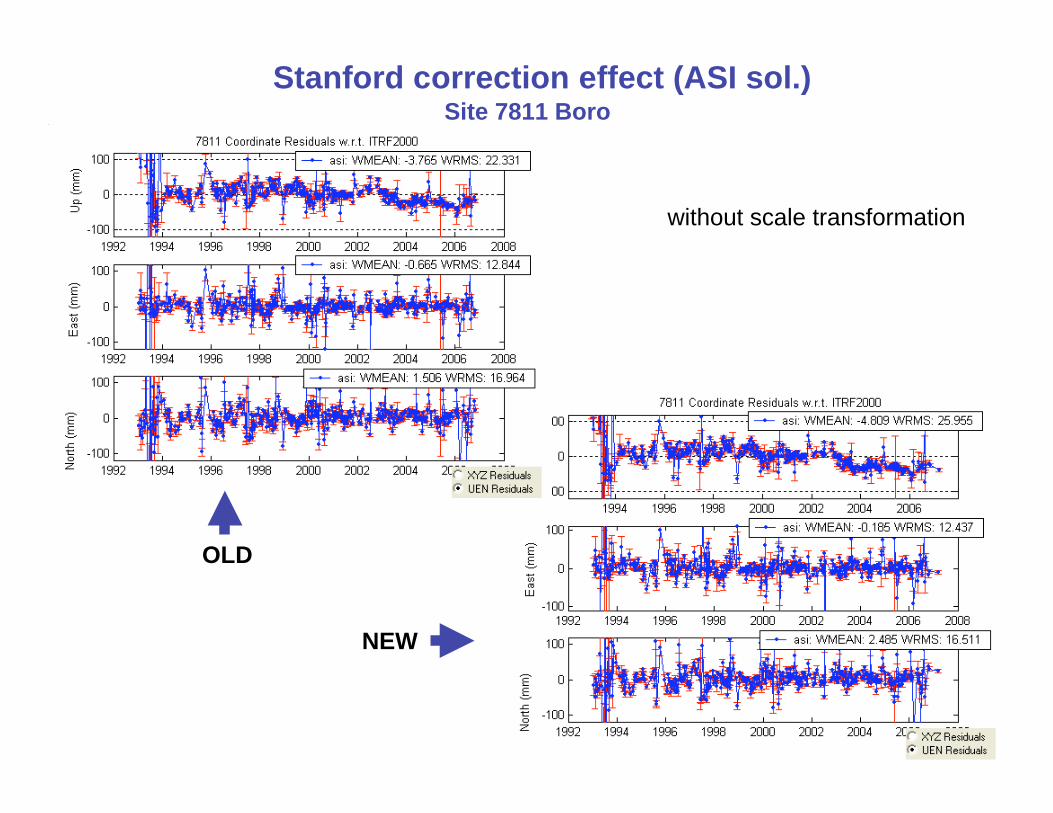
Stanford correction effect (ASI sol.)Site 7811 Boro
without scale transformation
OLD
NEW

Stanford correction effect (ASI sol.)
OLD
NEW
Site 7811 Boro – Lageos1 Range residuals (ITRF2000 coordinates)
SET
SET

Stanford correction effect (ASI sol.)Site 7810 Zimm
without scale transformation
OLD
NEW

Stanford correction effect (ASI sol.)
OLD
NEW
Site 7810 Zimm (423 nm) – Lageos1 Range residuals (ITRF2000 coordinates)
03/02/2006 – Stanford ET change29/5/2002 - Range bias removed
SET
SET
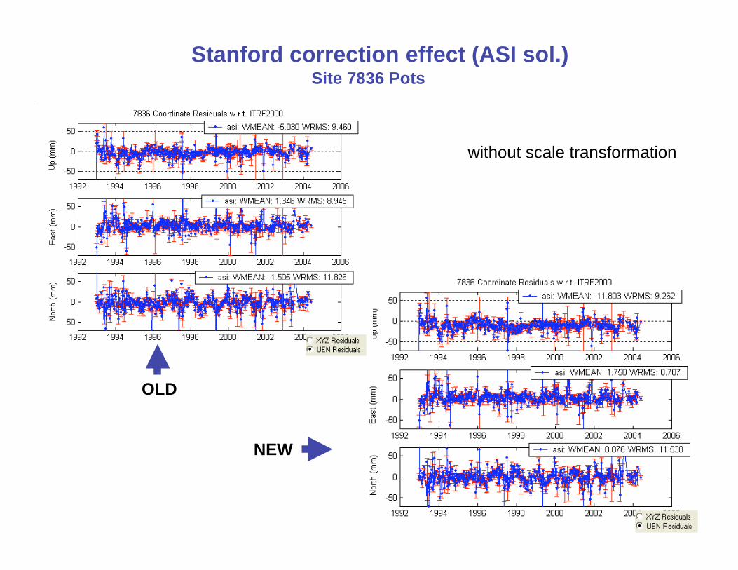
Stanford correction effect (ASI sol.)Site 7836 Pots
without scale transformation
OLD
NEW

OLD
NEW
Stanford correction effect (ASI sol.)Site 7836 Pots – Lageos1 Range residuals (ITRF2000 coordinates)
SET
SET

Stanford correction effect (ASI sol.)
OLD
NEW
Site 7841 Pots – Lageos1 Range residuals (ITRF2000 coordinates)
SET
SET

Open Points
- Scale effect of Stanford event timer corrections?


G.G. Bianco - Bianco - Agenzia Spaziale ItalianaAgenzia Spaziale Italiana
V. V. LuceriLuceri –– e-GEOSe-GEOS S.p.A. S.p.A.
ILRS AWG Meeting, 14 April 2007, Wien
ASI ASI operationaloperational productsproducts: 1983-1992 : 1983-1992 seriesseries
((versionversion 2) 2)

Analysis setup
- Standards agreed within the AWG, in particular: 15 day arc, 3-day EOP and
LOD, Marini-Murray
- Biases applied as indicated by Erricos Pavlis
- Biases estimated for
site from(yymmdd) to(yymmdd)
1864 all arcs
1884 all arcs
7210 all arcs
7237 all arcs
7811 880101 940101
7835 830101 980103
7839 910301 960928
8834 910101 961228
7080 830101 930101
7112 830101 850101
7122 830101 870120
7843 850101 920101
7838 830101 840205
7517 920601 920730
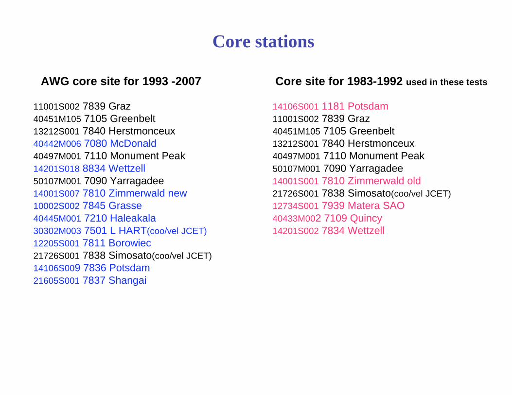
Core stations
11001S002 7839 Graz
40451M105 7105 Greenbelt
13212S001 7840 Herstmonceux
40442M006 7080 McDonald
40497M001 7110 Monument Peak
14201S018 8834 Wettzell
50107M001 7090 Yarragadee
14001S007 7810 Zimmerwald new
10002S002 7845 Grasse
40445M001 7210 Haleakala
30302M003 7501 L HART(coo/vel JCET)
12205S001 7811 Borowiec
21726S001 7838 Simosato(coo/vel JCET)
14106S009 7836 Potsdam
21605S001 7837 Shangai
AWG core site for 1993 -2007 Core site for 1983-1992 used in these tests
14106S001 1181 Potsdam
11001S002 7839 Graz
40451M105 7105 Greenbelt
13212S001 7840 Herstmonceux
40497M001 7110 Monument Peak
50107M001 7090 Yarragadee
14001S001 7810 Zimmerwald old
21726S001 7838 Simosato(coo/vel JCET)
12734S001 7939 Matera SAO
40433M002 7109 Quincy
14201S002 7834 Wettzell
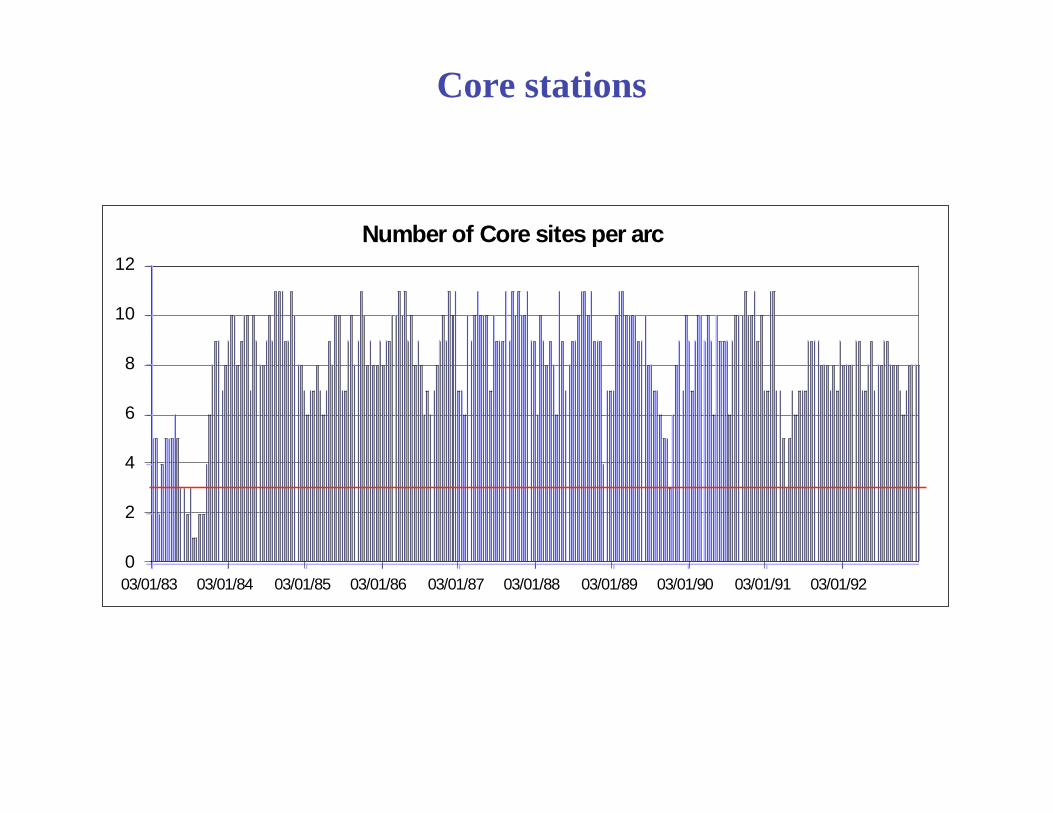
Core stations
Number of Core sites per arc
0
2
4
6
8
10
12
03/01/83 03/01/84 03/01/85 03/01/86 03/01/87 03/01/88 03/01/89 03/01/90 03/01/91 03/01/92

1983-1992: Translation w.r.t. ITRF2000

1983-1992: Scale w.r.t. ITRF2000

1983-1992: site coordinates
3-D coordinate residual WRMS w.r.t. ITRF2000
0
10
20
30
40
50
60
70
80
90
100
lug-83 lug-84 lug-85 lug-86 lug-87 lug-88 lug-89 lug-90 lug-91 lug-92 lug-93
mm
core
global

1983-1992: EOP

1984-1992: EOP

Open Points
- EOP only products to extend the IERS Operational series?
- List of core sites for ITRF constraints (i.e. quality check)
- Range biases to be estimated
ILRS Analysis Working Group Meeting, Vienna, April 14 2007
Status of the
ILRS 1983-1992 processing
Horst Müller
Deutsches Geodätisches Forschungsinstitut, München
E-Mail: [email protected]

ILRS Analysis Working Group Meeting, Vienna, April 14 2007
• Period 1993-2006 reprocessed and delivered
• NASA NP’s corrected to new CoM
• Processing of all arcs 1981 – 1992 finished
• Comparison with DGFI-NP solution shows differences
• Evaluation of these discrepancies is in progress
• Use of the slr_data_corrections.snx file foreseen next
• Check of the new DOGS version (diff. to older versions)
• Final delivery expected for the end of April

ILRS Analysis Working Group Meeting, Vienna, April 14 2007

ILRS Analysis Working Group Meeting, Vienna, April 14 2007
Quality assessment of new
SLR systems/sites
Horst Müller
Deutsches Geodätisches Forschungsinstitut, München
E-Mail: [email protected]

ILRS Analysis Working Group Meeting, Vienna, April 14 2007
General Aspects
• Data Quality• single shot precission
• no systematic errors (no biases, system calibration)
• Reliability
• certain number of passes per week (tbd)
• tracking of most targets
• Stability
• station should operate for a longer time span (tbd)

ILRS Analysis Working Group Meeting, Vienna, April 14 2007
Procedures
• Data Quality• processing of satellite arcs
• computation of range biases during the processing
• Reliability• fulfil station qualification from ILRS
• statistics at data centres
• Stability
• ?
ILRS Analysis Working Group Meeting, Vienna, April 14 2007
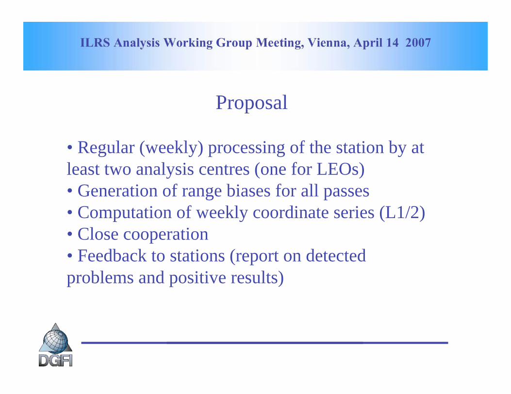
Proposal
• Regular (weekly) processing of the station by at
least two analysis centres (one for LEOs)
• Generation of range biases for all passes
• Computation of weekly coordinate series (L1/2)
• Close cooperation
• Feedback to stations (report on detected
problems and positive results)

ILRS Analysis Working Group Meeting, Vienna, April 14 2007

ILRS Analysis Working Group Meeting, Vienna, April 14 2007
First results on Haleakala coordinates 398 obs.
ITRF2000 Ref. Frame
X -5466067.710 ± 0.041
Y -2404339.593 ± 0.051
Z 2242109.090 ± 0.054
Very preliminary results for Arequipa 16 obs.
X 1942807.793 ± 0.442
Y -5804069.912 ± 0.240
Z -1796915.488 ± 0.523

ILRS Analysis Working Group Meeting, Vienna, April 14 2007
Conclusion
• Problem not easy to solve
• Some aspects still to be defined
• Close cooperation with stations to investigate
their needs
• ?
ILRS AWG Meeting Vienna,April 14, 2007
Status of ILRSB
Rainer KelmDeutsches Geodätisches Forschungsinstitut
Actual combination
Reanalysis 1993
Proposals

ILRS AWG Meeting Vienna,April 14, 2007
ilrsb.pos+eop.070407.v1.sum###########################
Summary file Version 1.2 (2006-06-30): solution from Wed Apr 11 07:23:10 2007*************************************
AC Deutsches Geodaetisches Forschungsinstitut MuenchenOUTPUT ILRS Combination Center: DGFICONTACT [email protected] DOGS_ASHARDWARE PC (LINUX)INPUT Global SLR data via CDDIS or EDC
Input solutions:----------------asi.pos+eop.070407.v1.snxbkg.pos+eop.070407.v1.snxdgfi.pos+eop.070407.v5.snxga.pos+eop.070407.v6.snxgfz.pos+eop.070407.v5.snxjcet.pos+eop.070407.v6.snx
Actual combination (1)

ILRS AWG Meeting Vienna,April 14, 2007
E^T*N*E = 0?
AC tx [m] ty [m] tz [m] rx [m] ry [m] rz [m] sc [ppb]---------------------------------------------------------------------------- asi 5.4e+06 5.89e+06 7.25e+05 16.4 16.5 0.908 1.02e+07 bkg 3.97e+06 4.27e+06 5.23e+05 1.08e-07 4.61e-08 0.00631 7.26e+06 dgfi 2.39e+06 2.12e+06 2.22e+05 46 54.9 -24 3.45e+06 ga 6.62e+06 7.52e+06 1.01e+06 39.3 40.9 18 1.2e+07 gfz 8.51e+06 8.19e+06 9.52e+05 225 201 0.00649 1.32e+07 jcet 9.45e+06 1.04e+07 1.3e+06 29.1 29 0.605 1.76e+07
Actual combination (2)

ILRS AWG Meeting Vienna,April 14, 2007
Variance factors and their variances (VCE)******************************************
asi.pos+eop.070407: 3.21294 0.13082 bkg.pos+eop.070407: 11.79487 0.37012dgfi.pos+eop.070407: 1.36680 0.06136 ga.pos+eop.070407: 24.41183 0.69992 gfz.pos+eop.070407: 0.35350 0.01154jcet.pos+eop.070407: 1.58929 0.08698
Actual combination (3)
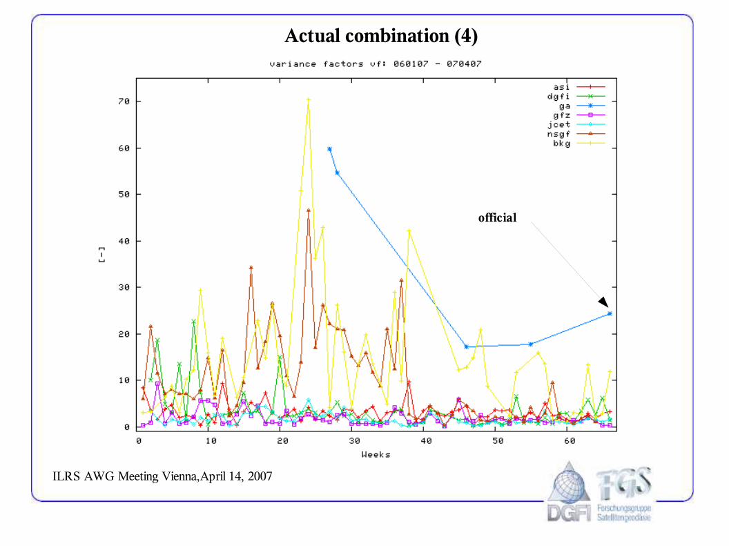
ILRS AWG Meeting Vienna,April 14, 2007
Actual combination (4)
official

ILRS AWG Meeting Vienna,April 14, 2007
Actual combination (5)
official

ILRS AWG Meeting Vienna,April 14, 2007
Actual combination (6)

ILRS AWG Meeting Vienna,April 14, 2007
Actual combination (7)

ILRS AWG Meeting Vienna,April 14, 2007
Actual combination (8)

ILRS AWG Meeting Vienna,April 14, 2007
Actual combination (9)
ILRS AWG Meeting Vienna,April 14, 2007
Actual combination (10)
ILRS AWG Meeting Vienna,April 14, 2007
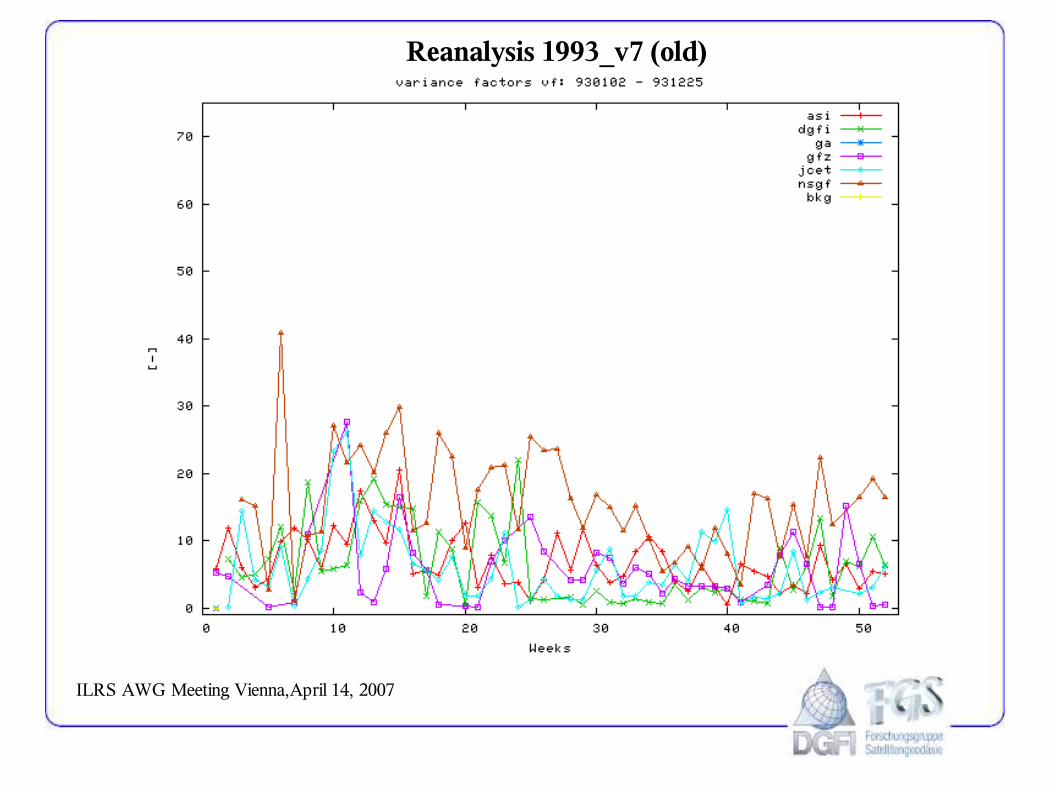
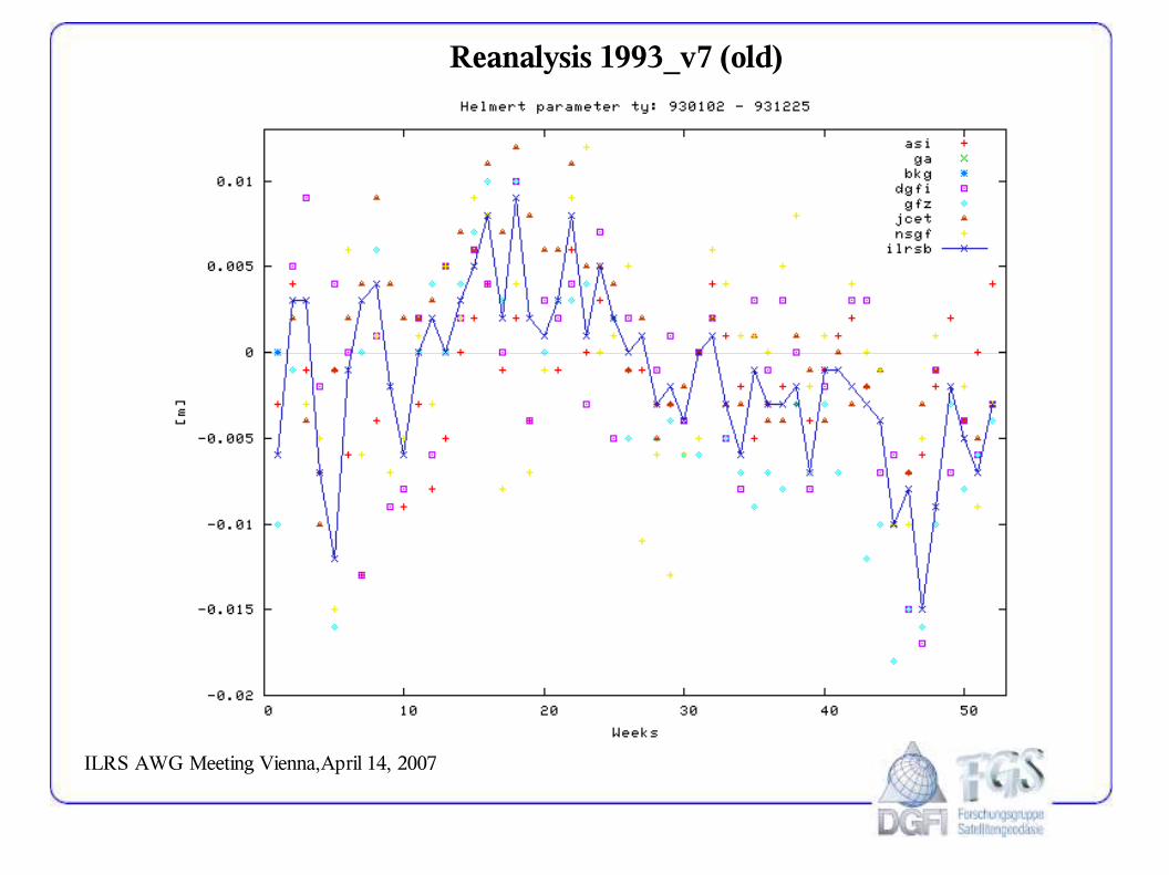
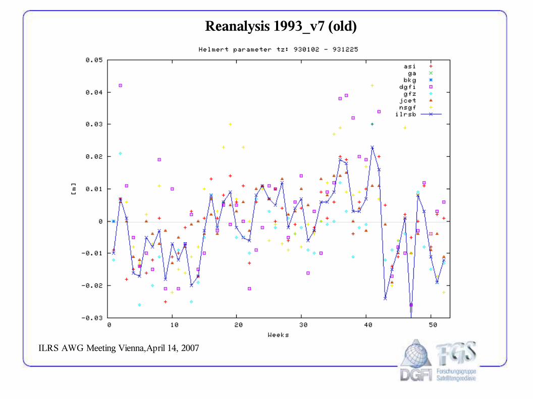
Reanalysis 1993_v7 (old)

ILRS AWG Meeting Vienna,April 14, 2007
Reanalysis 1993_v6 (new)

ILRS AWG Meeting Vienna,April 14, 2007
Reanalysis 1993_v7 (old)

ILRS AWG Meeting Vienna,April 14, 2007
Reanalysis 1993_v6 (new)

ILRS AWG Meeting Vienna,April 14, 2007
Reanalysis 1993_v7 (old)

ILRS AWG Meeting Vienna,April 14, 2007
Reanalysis 1993_v6 (new)
ILRS AWG Meeting Vienna,April 14, 2007
Reanalysis 1993_v7 (old)

ILRS AWG Meeting Vienna,April 14, 2007
Reanalysis 1993_v6 (new)
ILRS AWG Meeting Vienna,April 14, 2007
Reanalysis 1993_v7 (old)

ILRS AWG Meeting Vienna,April 14, 2007
Reanalysis 1993_v6 (new)

ILRS AWG Meeting Vienna,April 14, 2007
Reanalysis 1993_v7 (old)

ILRS AWG Meeting Vienna,April 14, 2007
Reanalysis 1993_v6 (new)

ILRS AWG Meeting Vienna,April 14, 2007
Reanalysis 1993_v7 (old)

ILRS AWG Meeting Vienna,April 14, 2007
Reanalysis 1993_v6 (new)

ILRS AWG Meeting Vienna,April 14, 2007
Proposals
* newest version in actual directory at CDDIS and EDC
* two-digit version numbering: 10, 11, 12, ... ( proposal of Cecilia a long time ago)

04/12/2007 02:33 PMsatellite information as a function of range
Page 1 of 2file:///Users/mtorrenc/Documents/files%20and%20data/ILRS%20stuff/info_fn_LclTme_and_Rng/plots_and_html/YARL_index.html
Yarragadee, Australia satellite information as a function of local time and satellite range
timespan begins April 1, 2006 and ends March 31, 2007
satellitelocal time range
satellitelocal time range
npt rms numFR/npt npt rms numFR
/npt npt rms numFR/npt npt rms numFR
/npt
ANDE-Act5 sec
Jason-115 sec
ANDE-Pas5 sec
Ajisai30 sec
CHAMP5 sec
LAGEOS-2120 sec
GRACE-A5 sec
LAGEOS-1120 sec
GRACE-B5 sec
Etalon-1300 sec
ICESat5 sec
Etalon-2300 sec
Larets30 sec
GLONASS-89300 sec
ALOS15 sec
GLONASS-95300 sec
ERS-215 sec
GLONASS-99300 sec
Envisat15 sec
GPS-36300 sec
GFO-115 sec
GPS-35300 sec
Starlette30 sec
GIOVE-A300 sec
Stella30 sec
ETS-8300 sec
Beacon-C15 sec
this page made Apr. 11, 2007

Stations http://ilrs.gsfc.nasa.gov/stations/index.html
1 of 1 4/12/07 2:41 PM
ILRS Home Stations Stations
Site Listing
Site Information
Global Report Cards
Groundtrack of the Last Seven Days of Geodetic Satellite Data
Station Charts for Last Year
Station Charts Since 2000
Site Procedures / Requirements
Current Network Status
Network Map
Stations
Operational and Associate stations as of latest ILRS quarterly report card(following ILRS station qualification criteria)
Responsible Government Official: Carey NollNASA's Privacy Policy and Important Notices
Send us your comments
Last modified date: Thursday, January 11, 2007Author: Carey Noll
Maintained by: Carey Noll

ILRS Products http://ilrs.gsfc.nasa.gov/products_formats_procedures/products.html
1 of 1 4/12/07 2:37 PM
ILRS Home Data & Products Official ILRS Products
Official ILRS Products
Official ILRS Products Description
Normal Point Data
Full-Rate Data
Predictions
Consolidated Laser Ranging Data (CRD) Format
Data Corrections
Official Satellite Names
Restricted Tracking Information
Site Positions and Velocities
Data Flow
FTP Archives
ILRS ProductsOfficial ILRS products consist of solutions for station coordinates and Earth Orientation Parameters (EOPs). The ILRS generates weekly,unconstrained solutions for station coordinates (valid for the mid-point of each 7-day interval) and EOPs (x-pole, y-pole and Length-Of-Day(LOD), all at 1-day intervals). These results are stored in subdirectories "pos+eop/YYMMDD", where "YYMMDD" is the date (YY=2 digit year,MM=2 digit month, and DD=2 digit day) of the end of each 7-day interval. Within each subdirectory, are the solutions from the combinationcenters and individual analysis centers.
click on the thumbnail to view a larger image of the location of the tacking data, click on the links to download the solution file via ftp
Solution end date, gps week, and data location
combination solution *
analysis center contributions
asi bkg dgfi ga gfz jcet ngsf
200703311420
pos+eop eop sum snx snx
snx snx snx snx snx snx snx
200703241419
pos+eop eop sum snx snx
snx snx snx snx snx snx snx
200703171418
pos+eop eop sum snx snx
snx snx snx snx snx snx snx
200703101417
pos+eop eop sum snx snx
snx snx snx snx snx snx snx
200703031416
pos+eop eop sum snx snx
snx snx snx n/a snx snx snx
* pos+eop: SUMmary file assessing the quality of solution and a SiNeXformat solution file for combination POSition and Earth Orientation Parameter solution
eop: a SiNeX format solution file for the EOP combinationproduct
The official primary ILRS combination products are formed by ASI Space Geodesy Center. The ILRS's official backup combination center is Deutsches Geodatisches Forschungsinstitut (DGFI). The combination products, and the individual ILRS analysis center contributions to the official combination pos+eop and eop product can be downloaded from the ILRS ftp archive labeled as:
ftp://cddis.gsfc.nasa.gov/pub/pub/slr/products/pos+eop/ YYMMDD/CENTER.pos+eop.YYMMDD.vN.sum ftp://cddis.gsfc.nasa.gov/pub/pub/slr/products/pos+eop/ YYMMDD/CENTER.pos+eop.YYMMDD.vN.snx ftp://cddis.gsfc.nasa.gov/pub/pub/slr/products/pos+eop/ YYMMDD/CENTER.eop.YYMMDD.vN.snx
Here, "CENTER" is replaced by either "ilrsa", or "ilrsb", or the abreviated name of the analysis center. The version number "N" for first solution that is generated for this period is labeled as "1". If re-computations are necessary, the version number, "N", will be increased by one. Theresults are stored in the SINEX format (".snx"). The reader is refered to the COMMENTS section of each solution (in the file itself) or moregeneral explanations of SINEX for further details of the solution and/or the format.
The individual analysis center solutions as well as the combination solutions are monitored on a weekly basis with a graphical and a statisticalpresentation of these time series available at: site hosted by the JCET analysis center http://geodesy.jcet.umbc.edu/ILRS_QCQA
For more information and/or suggestions, please contact the CDDIS/EDC Data Center representatives (Carey Noll or Wolfgang Seemueller respectively) or the ILRS Analysis Coordinators (Erricos Pavlis or Cinzia Luceri).
NOTICE: It is important that you acknowledge the ILRS in your papers and presentations that rely on SLR and results. Please reference thefollowing citation:
Pearlman, M.R., Degnan, J.J., and Bosworth, J.M., "The International Laser Ranging Service", Advances in Space Research, Vol.30, No. 2, pp. 135-143, July 2002.
Furthermore, please include SLR as a keyword in your papers. The SLR community relies on these acknowledgements and references tostrengthen its requests for continued support from its funding organizations. The Central Bureau asks that you provide a link to and/or bibliographic reference of any SLR/LLR-related papers or presentations.
Responsible Government Official: Carey NollNASA's Privacy Policy and Important Notices
Send us your comments
Last modified date: Tuesday, April 10, 2007 Author: Mark Torrence Maintained by: Carey Noll

SLR Global Performance Report Card http://ilrs.gsfc.nasa.gov/stations/site_info/global_report_cards/perf_2007q1_wLLR.html
1 of 2 4/12/07 2:40 PM
ILRS Home Stations Site Information Global Report Cards SLR Global Performance Report Card
2007 1st Quarter
2006 4th Quarter
2006 3rd Quarter
2006 2nd Quarter
2006 1st Quarter
2005 4th Quarter
2005 3rd Quarter
2005 2nd Quarter
2005 1st Quarter
2004 4th Quarter
2004 3rd Quarter
2004 2nd Quarter
2004 1st Quarter
2003 4rd Quarter
2003 3rd Quarter
2003 2nd Quarter
2003 1st Quarter
2002 4th Quarter
2002 3rd Quarter
2002 2nd Quarter
2002 1st Quarter
2001 4th Quarter
2001 3rd Quarter
2001 2nd Quarter
2001 1st Quarter
2000 4th quarter
2000 3rd quarter
2000 2nd quarter
2000 1st quarter
1999 4th quarter
1999 3rd quarter
1999 2nd quarter
1999 1st quarter
SLR Global Performance Report CardApril 1, 2006 through March 31, 2007
The performance report card is divided into three tables for readability. Table 1 contains performance parameters based on data volume, on-site processing statistics andoperational compliance issues. Table 1 L contains information about Lunar Laser Ranging during the past year. Table 2 contains performance parameters based on variousAnanlysis Cente's rapid orbital analysis results.
Below are the detailed descriptions of each column in Table 1 plots of the columns are linked in this description and in Table 1:
Column 1 is the station location name.Column 2 is the monument marker number.Column 3 is the LEO pass total during the past 12 months.Column 4 is the LAGEOS pass total during the past 12 months.Column 5 is the high satellite pass total during the past 12 months.Column 6 is the pass total (i.e., all satellites) during the past 12 months.Column 7 is the LEO NP total during the past 12 months.Column 8 is the LAGEOS NP total during the past 12 months.Column 9 is the high satellite NP total during the past 12 months.Column 10 is the NP total (i.e., all satellites) during the past 12 months.Column 11 is the total tracking minutes (i.e., all satellites) during the past 12 months. This is computed by the summation of the number of normal points multiplied by itsbin size in minutes.Column 12 is the average single-shot calibration RMS, in millimeters, during the last quarter.Column 13 is the average single-shot Starlette RMS, in millimeters, during the last quarter.Column 14 is the average single-shot LAGEOS RMS, in millimeters, during the last quarter.
The first entry in each table is for the performance baseline goal. Note: There are no baseline goals for NP data quantities, single shot RMS's.
Additional Notes: Blanks in any columns implies either that there was no data or that there was insufficient data. Only stations that have supplied data within the last year areincluded in the table. The table is sorted in descending order by total passes.
Table 1
Site Information Data Volume Data QualityColumn 1 2 3 4 5 6 7 8 9 10 11 12 13 14
Location StationNumber
LEO passTot
LAGEOSpass Tot
High passTot
Totalpasses LEO NP
TotalLAGEOSNP Total
High NPTotal
TotalNP
Minutes ofData
Cal.RMS
StarRMS
LAGRMS
Baseline 1000 400 100 1500 Yarragadee 7090 9048 1996 1368 12412 176336 26510 13753 216599 85814 4.8 8.4 9.4Zimmerwald_423Zimmerwald_846 7810 5448
541511841202
860820
74927437
8986289751
1599618098
57405809
111598113658
4135543478
11.924.5
14.924.3
16.825.8
San_Juan 7406 4806 1171 1178 7155 66823 13458 6047 86328 39337 6.5 9.2 11.9Mount_Stromlo_2 7825 5154 1403 578 7135 68060 15755 4626 88441 39664 3.4 6.4 9.1Graz 7839 5200 855 572 6627 103813 9597 4863 118273 32220 2.4 3.9 8.0Riyadh 7832 4279 1093 821 6193 56690 9971 4628 71289 29563 9.5 19.4 18.7Wettzell 8834 4523 990 555 6068 56898 8095 3158 68151 24616 5.0 13.5 18.6Monument_Peak 7110 4378 945 341 5664 86396 10532 3312 100240 27591 4.9 13.2 14.4Herstmoncex 7840 3833 985 419 5237 61558 12960 2017 76535 23582 7.9 12.1 15.1Changchun 7237 3607 510 393 4510 45778 4292 2068 52138 14885 9.2 12.9 14.1Matera_MLRS 7941 2586 864 199 3649 35622 9961 1599 47182 19581 1.8 4.4 5.7Hartebeesthoek 7501 2455 681 200 3336 37645 7186 1883 46714 17495 5.1 7.9 9.5Simosato 7838 2023 515 7 2545 38577 7705 67 46349 12745 5.3 5.6 8.6Potsdam_3 7841 2055 313 2368 39130 3902 43032 6856 12.4 17.2 20.6San_Fernando 7824 2002 316 2318 30735 2558 33293 5646 6.0 11.2 15.4Greenbelt 7105 1840 315 66 2221 38709 3339 399 42447 7580 4.8 9.3 9.5McDonald 7080 1253 419 291 1963 14328 3911 1226 19465 8637 12.6 12.0 12.5Beijing 7249 1386 199 66 1651 17614 1797 425 19836 5427 13.2 34.0 20.3Shanghai_2 7821 1314 123 10 1447 16316 1201 69 17586 3288 15.1 25.7 33.6Maidanak_1 1864 757 191 234 1182 7771 1688 909 10368 5256 63.0 69.7Riga 1884 1061 93 8 1162 20409 1113 44 21566 2360 7.3 10.6 12.2Katzively 1893 761 105 30 896 12693 839 178 13710 2693 32.2 44.1 41.6Borowiec 7811 642 94 4 740 9808 932 15 10755 1981 19.1 20.8 24.2Papeete 7124 518 131 649 7679 1168 8847 1993 4.4 7.6 Koganei 7308 406 104 108 618 6364 1205 762 8331 4478 8.9 11.8 14.6Simeiz 1873 477 108 2 587 5595 982 13 6590 1796 98.6 54.5Arequipa 7403 390 42 432 3524 301 3825 819 5.4 7.4 5.0Haleakala 7119 264 46 310 3915 437 4352 990 4.8 11.5 9.6Tanegashim 7358 204 23 19 246 2723 220 78 3021 755 2.9 4.0 5.5Concepcion_423Concepcion_847 7405 122
164733
766
149155
25621320
22747304
8953
11281624
32828626
165624.27.3
10.331.9
11.561.7
Lviv 1831 47 47 738 738 101 NRL 7865 9 9 131 131 19.5 Helwan 7831 9 9 92 92 4 Kiev 1824 1 1 12 12 4 47.4
Below are the detailed descriptions of each column in Table 1 L:
the first column, L1, is the station location name.the second column, L2, is the monument marker number.the third column, L3, is the number of nights during the past 12 months in which there were Lunar ranging measurements

SLR Global Performance Report Card http://ilrs.gsfc.nasa.gov/stations/site_info/global_report_cards/perf_2007q1_wLLR.html
2 of 2 4/12/07 2:40 PM
1998 4th quarter
1998 3rd quarter
1998 2nd quarter
1998 1st quarter
1997 4th quarter
1997 3rd quarter
the fourth column, L4, is the number of Lunar Laser Ranging normal points during the past 12 monthsthe fifth column, L5, is the number of Lunar Laser Ranging normal points during the past 3 monthsthe sixth column, L6, is the average Lunar Laser Ranging normal points rms 3 months in mm
Table 1 L
Site Information Data InformationColumn L1 L2 L3 L4 L5 L6
Location StationNumber
num nights trackinglast 12 mon
num nptlast 12 mon
num nptslast 3 mon
ave npt rmslast 3 mon
McDonald 7080 72 116 26 61.4
Below are the detailed descriptions of each column in Table 2:
the first column is the station location name.the second column is the monument marker number.following columns are in grouped by analysis center with four columns for each
the first AC column is the average LAGEOS normal point RMS, in millimeters, during the last quarterthe second AC column is the measure of short term bias stability, in millimeters, during the last quarter. The short term stability is computed as the standarddeviation about the mean of the pass-by-pass range biases (minimum number of passes in quarter is 10)the third AC column is the measure of long term bias stability, in millimeter, during the past year. The long term stability is the standard deviation of the monthly range bias estimates. A station must have tracked LAGEOS (1,2) in at least 8 of the last 12 months in order to compute this metric.the fourth AC column is the percentage of LAGEOS normal points that were accepted in the analysis.
The first entry in each table is for the performance baseline goal.
Additional Notes: Blanks in any columns implies either that there was no data or that there was insufficient data. Only stations that have supplied data within the last year areincluded in the table. The table is sorted in descending order by total data volume.
Table 2
Site Information NICT Orbital Analysis MCC Orbital Analysis SHAO Orbital Analysis
StationLocation
StationNumber
LAGNP
RMS(mm)
shortterm(mm)
longterm(mm)
%goodLAG.
NP
LAGNP
RMS(mm)
shortterm(mm)
longterm(mm)
%goodLAG.
NP
LAGNP
RMS(mm)
shortterm(mm)
longterm(mm)
%goodLAG.
NPBaseline 10.0 20.0 20.0 95 10.0 20.0 20.0 95 10.0 20.0 20.0 95Yarragadee 7090 2.0 9.1 1.3 100.0 2.3 12.6 6.8 98.5 2.2 16.1 2.0 95.2Zimmerwald_423Zimmerwald_846 7810 2.7
3.79.75.8
3.32.9
99.9100.0
3.2
8.1
10.4
96.2
2.93.1
11.311.0
2.63.2
94.294.1
San_Juan 7406 2.6 19.7 13.2 98.8 3.8 11.9 99.5 2.7 23.6 95.6Mount_Stromlo_2 7825 3.8 12.3 1.5 98.7 4.3 18.1 3.1 92.8 3.5 17.9 2.2 94.6Graz 7839 1.2 5.3 2.9 100.0 1.8 5.7 5.1 99.2 1.3 11.3 2.0 95.7Riyadh 7832 2.7 12.2 3.6 99.8 3.7 13.9 4.8 96.6 3.0 21.8 3.7 95.8Wettzell 8834 3.3 11.4 3.7 100.0 3.1 14.6 9.2 97.1 3.3 15.7 3.1 96.3Monument_Peak 7110 2.0 11.2 1.5 100.0 2.2 14.1 3.5 98.4 2.1 13.5 2.6 95.7Herstmoncex 7840 1.6 7.3 1.6 100.0 2.7 9.8 3.8 98.7 2.2 11.7 3.1 96.6Changchun 7237 7.0 22.0 6.9 99.9 7.1 19.9 17.3 96.0 6.0 27.6 8.1 96.1Matera_MLRS 7941 2.7 13.9 7.5 100.0 2.4 15.3 10.3 97.7 Hartebeesthoek 7501 2.2 10.5 4.5 100.0 2.1 10.2 3.7 97.5 3.3 15.8 4.3 98.0Simosato 7838 3.0 13.0 8.4 99.8 4.8 13.1 9.8 99.6 5.0 19.1 9.2 95.5Potsdam_3 7841 4.1 12.8 4.2 99.5 5.0 15.5 13.1 90.0 San_Fernando 7824 2.6 14.1 9.2 100.0 3.9 14.9 15.1 99.6 3.7 19.1 14.8 95.2Greenbelt 7105 1.7 8.5 5.5 100.0 2.0 15.7 10.8 98.7 2.2 15.1 3.9 94.8McDonald 7080 2.3 10.2 4.7 99.9 3.0 11.7 7.6 96.7 2.2 15.4 6.4 94.9Beijing 7249 9.9 21.3 7.6 91.8 13.8 16.8 18.4 88.3 8.9 23.1 9.4 85.9Shanghai_2 7821 9.9 25.2 12.0 100.0 11.2 22.6 98.9 9.6 29.4 18.2 95.8Maidanak_1 1864 22.9 24.7 11.3 90.0 21.9 32.6 9.2 80.4 25.1 24.5 10.2 69.8Riga 1884 6.5 25.8 23.8 100.0 6.8 29.7 27.4 94.2 5.1 14.8 21.4 94.0Katzively 1893 7.0 21.9 7.3 98.9 6.7 23.4 8.9 94.5 7.6 26.5 28.0 92.9Borowiec 7811 9.9 11.5 5.8 100.0 Koganei 7308 3.3 18.8 18.1 99.9 4.8 21.7 13.4 97.8 4.2 22.7 17.9 95.8Simeiz 1873 73.1 48.4 46.0 95.0 44.5 50.9 48.3 78.1 37.6 27.3 28.3 70.4Haleakala 7119 1.8 11.1 100.0 Concepcion_423Concepcion_847 7405
2.1
11.3
4.2
99.9
3.3
14.4
6.7
99.42.6
23.3
96.4
Responsible Government Official: Carey NollNASA's Privacy Policy and Important Notices
Send us your comments
Last modified date: Tuesday, April 3, 2007 Author: Mark Torrence
Maintained by: Carey Noll

EGU General AssemblyVienna, 15-20 April, 2007
Some Effects of Data Handling and Background Models on the SLR Dynamical and Geometrical
Reference Frame
R. König, K.H. Neumayer, M. Vei

EGU General AssemblyVienna, 15-20 April, 2007
Effect of
individual stations / network configuration
systematic corrections to range observations
a priori coordinates
on the
dynamic
geometric
reference frame
Motivation

EGU General AssemblyVienna, 15-20 April, 2007
2 Solutions:
SLR test solution for year 2004 within GGOS-D
14-year series 1993-2004 within ILRS reanalysis
GGOS-D standards different than for ILRS AC duties for pos&eop
EIGEN gravity model
FES2004
Corresponding ocean tide loading site displacements
Recently introduced systematic corrections within ILRS ACs for pos&eop
Stanford counter range biases for individual stations and periods
Tropospheric range correction model change
ITRF2000 / ITRF2005(rescaled)
Introduction

EGU General AssemblyVienna, 15-20 April, 2007
Solved for parameters in weekly solutions from LAGEOS-1 and -2
GGOS-D: ILRS AC:
Station coordinates, a priori sigma 1 m dto.
X-, Y-pole, UT1; @0:00; a priori sigma 1 m dLOD; @12:00
Degree 0 to 2 harmonics, a priori sigma 1 m NO
Range biases for a few stations, free dto.
Initial states of LAGEOS-1 and -2, free dto.
Empirical accelerations for LAGEOS-1 and -2, free dto.
Rank deficiency without a priori sigmas = 3
the rotations need a datum dto.
Parametrization

EGU General AssemblyVienna, 15-20 April, 2007
Spurious Stations
Peak in C(0,0) and in HT (Helmert transformation) scale (DM) time series
Standard data screening and processing sees no spurious station

EGU General AssemblyVienna, 15-20 April, 2007
Spurious Stations, II
Empirical remove-restore search for peak driving station
Spurious from C(0,0):
7355 Urumqi
dto. from HT scales:
7249 Beijing
=> both removed

EGU General AssemblyVienna, 15-20 April, 2007
Spurious Stations, III
BUT: peaks in C(1,1), S(1,1), TX, TY and other series, e.g. S(2,2), remain

EGU General AssemblyVienna, 15-20 April, 2007
Stanford Counter Range Bias Corrections
1824 San Fernando 16 mm since 99:314
1893 Katsively 10 mm since 98:171
7231 Wuhan 10 mm since 99:001
7249 Beijing 22 mm since 01:020
7406 San Juan 10 mm since 06:020
7810 Zimmerwald 11 mm since 97:001
...
7840 Herstmonceux 18.5 mm from 93:001 to 02:032
8.5 mm from 02:032 to 07:042
...

EGU General AssemblyVienna, 15-20 April, 2007
Tropospheric Range Correction
Difference of the Mendes-Pavlis model to Marini-Murray for a one-week arc
EGU General AssemblyVienna, 15-20 April, 2007
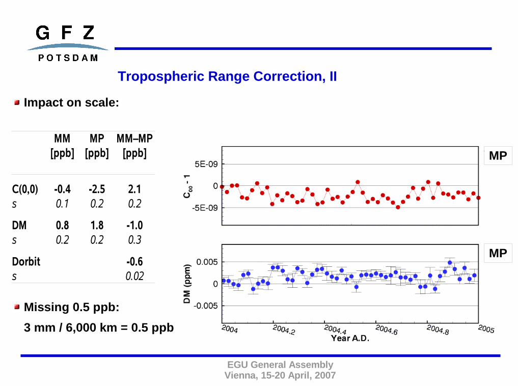
Tropospheric Range Correction, II
Impact on scale:
Missing 0.5 ppb:
3 mm / 6,000 km = 0.5 ppb
MM MP MM–MP
C(0,0) -0.4 -2.5 2.10.1 0.2 0.2
DM 0.8 1.8 -1.0s 0.2 0.2 0.3
-0.6s 0.02
[ppb] [ppb] [ppb]
s
Dorbit
MP
MP

EGU General AssemblyVienna, 15-20 April, 2007
Long Series ILRS Reanalysis
Pos&eop standards: (low degree harmonics not solved for !! )
v5 - v3:
Stanford counter range biases applied
Mendes-Pavlis tropospheric correction applied
Bias 0.5 ppb @ 1999Trend 0.05 ppb/a

EGU General AssemblyVienna, 15-20 April, 2007
Long Series ILRS Reanalysis, II
Bias 2.5 ± 0.1 mmTrend -0.2 ± 0.03 mm/a
Bias -2.6 ± 0.1 mmTrend -0.1 ± 0.03 mm/a
Bias 0.6 ± 0.2 mmTrend -0.6 ± 0.07 mm/a

EGU General AssemblyVienna, 15-20 April, 2007
ITRF2000 / ITRF2005(“rescaled”) as A Priori
Impact on scale:
➢ Difference ITRF2000 vs. ITRF2005_rescaled amounts to 0.4 ppb in 2004
ITRF2000 ITRF2005r 2000-2005r[ppb] [ppb] [ppb]
C(0,0) -2.5 -2.5 0.0s 0.2 0.2 0.3
DM vs. ITRF2000 1.8 1.4 0.4s 0.2 0.2 0.3
DM vs. ITRF2005r 1.5 1.1 0.4s 0.2 0.2 0.3
Dorbit 0.0s 0.0

EGU General AssemblyVienna, 15-20 April, 2007
Old: Scherneck/Schwidersky, hard-coded (not all stations)
New: Scherneck, FES2004, Earth CoM considered
➢ Orbital fit improves considerable➢ Geocenter X and Y series move closer to E{ . } = 0 and become more stable
Ocean Loading Site Displacements
Old New
Orbital Fit 1.06 cm / 134,638 0.96 cm / 134,638
C(1,1)
S(1,1)
TX
TY
0.89 ± 0.18 cm 0.19 ± 0.11 cm
0.49 ± 0.11 cm 0.18 ± 0.08 cm
-1.27 ± 0.26 cm -0.24 ± 0.18 cm
-0.90 ± 0.17 cm -0.49 ± 0.12 cm

EGU General AssemblyVienna, 15-20 April, 2007
Summary
Weak network (<15 stations, <1000 observations / week) could produce spurious
results
Systematic corrections of the range observations have influence on scale and
origin of the reference frame:
Tropospheric range correction change: ~0.5 ppb
Long term: 0.5 ppb / 10 a in geometric scale
Significant biases in the millimeters and trends in the sub-millimeters per year
for the geometric origin
ITRF2000 to ITRF2005r changes geometric scale by 0.4 ppb in 2004
Up-to-date ocean loading site displacement models improve dynamic and
geometric origin and more
Impact of SLR biases on TRF scale factor
GRGS team

Range biases directly linked to SLR station instrumentationsand SLR instrumentations do not change all the time.
We can suppose range biases constant over given periods of time.
Estimation of range biases over “long” periods of time together with weekly stationpositions.
Correlation between biases and station vertical components decreases.
Limits of the time intervals over which the range biases are supposed to beconstant correspond to station instrumental changes. The corresponding times arefound in station log files, in SLR mails and in the ILRS official eccentricity file.
See http://maestro.obs-azur.fr/cgi-bin/query_mrb.pl.
Temporal de-correlation method
Two opposite strategies
1- No bias is estimated nor applied during the SLR data processing.2- Measurements are corrected by the biases estimated with the temporal de-correlation method during the SLR data processing.
Weekly SINEX derived by the two strategies are stacked with CATREFsoftware.

Strategy 1 (No bias)
Three translations andscale factor betweenweekly TRFs and ITRF2000(mm).
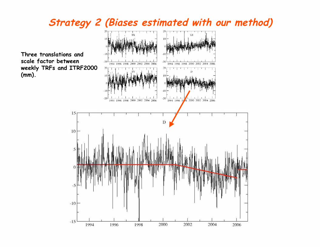
Strategy 2 (Biases estimated with our method)
Three translations andscale factor betweenweekly TRFs and ITRF2000(mm).

-0.05 -0.2 +/- 0.04-1.9 -0.5 +/- 0.051993.0-2006.9
-0.9 0.0 +/- 1.6-5.7 2.2 +/- 1.82006.0-2006.9
-1.1 -0.7 +/- 0.2-2.9 -2.5 +/- 0.22001.0-2006.0
0.7 0.3 +/- 0.20.4 1.0 +/- 0.21996.0-2001.0
0.7 0.3 +/- 0.3-2.9 -0.3 +/- 0.31993.0-1996.0
Mean Value (mm) Drift +/- St. Dev. (mm/yr)Mean Value (mm) Drift +/- St. Dev. (mm/yr)XXXX.X-XXXX.X
With Biases (Strategy 2)Without Any Bias (Strategy 1)Time Interval
Comparisons between the two strategies
Strategy 1 Strategy 2
Zimmerwald (7810) station vertical component time series in ITRF2000 (mm)
See our poster “Satellite Laser Ranging biases and Terrestrial Reference Frame scale factor”by Coulot et al., abstract n°EGU2007-A-07027, session G1, Tuesday, 17 April 2007.
Slides Presented by
Zuheir Altamimi
Vienna ILRS AWG
April 14, 2007
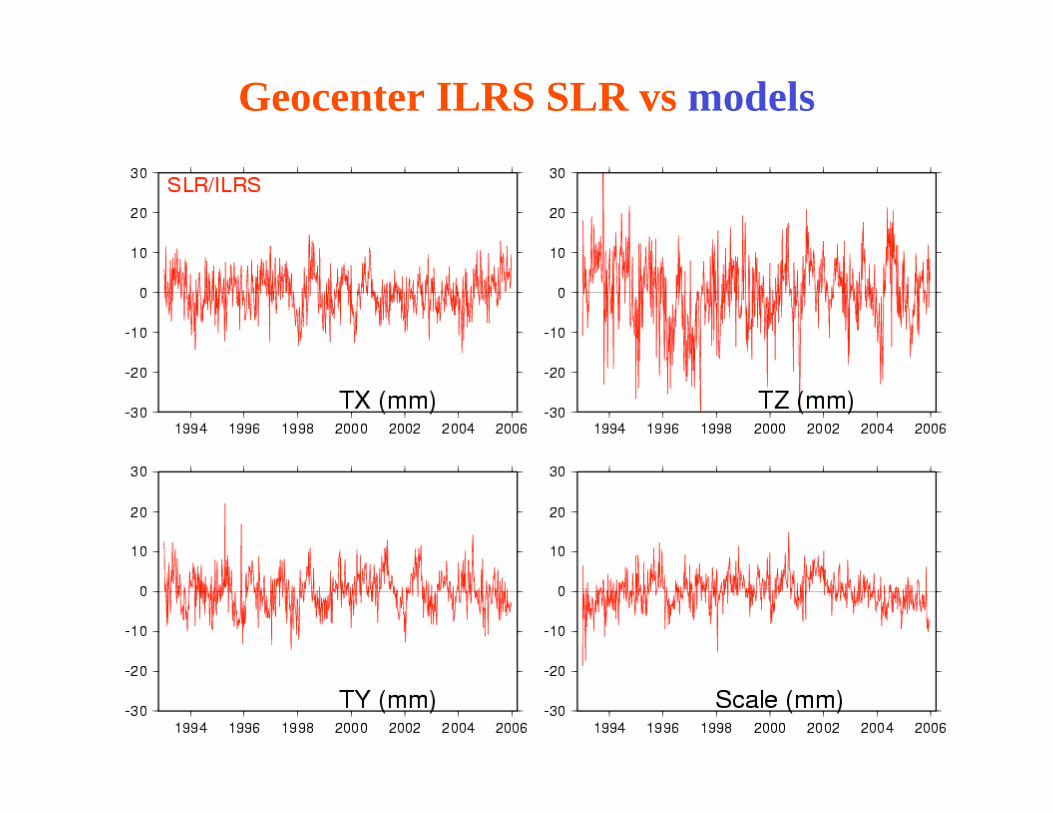
Geocenter ILRS SLR vs models

Geocenter ILRS SLR vs GPS+OBP model
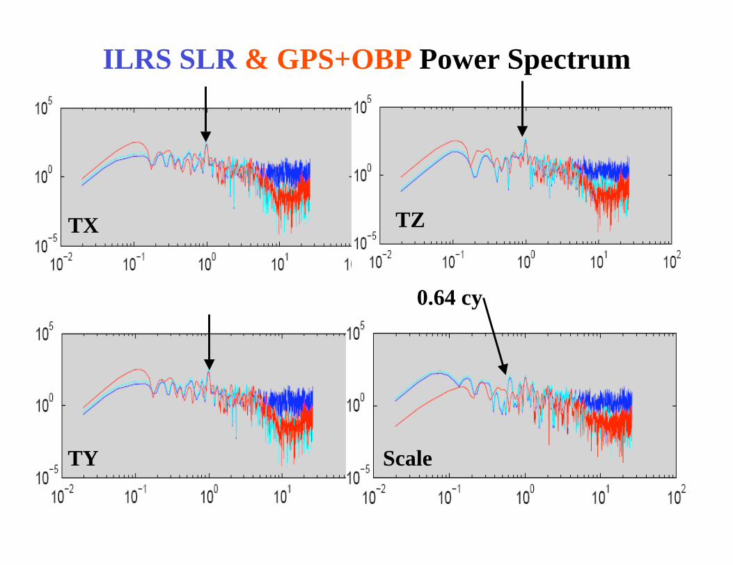
ILRS SLR & GPS+OBP Power Spectrum
0.64 cy
TX
TY
TZ
Scale
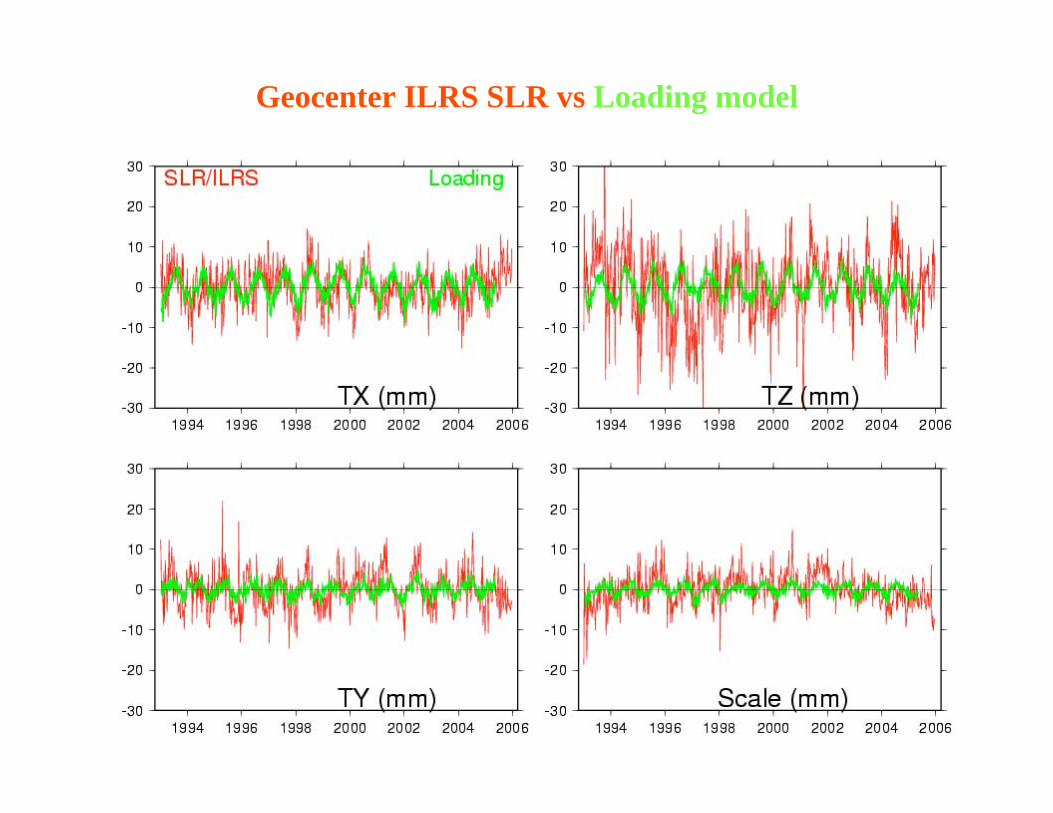
Geocenter ILRS SLR vs Loading model

Geocenter ILRS SLR vs GPS+OBP and Loading models

ILRS SLR Intrinsic origin and scale
(ITRF2005 + 64 weeks)
ITRF2005
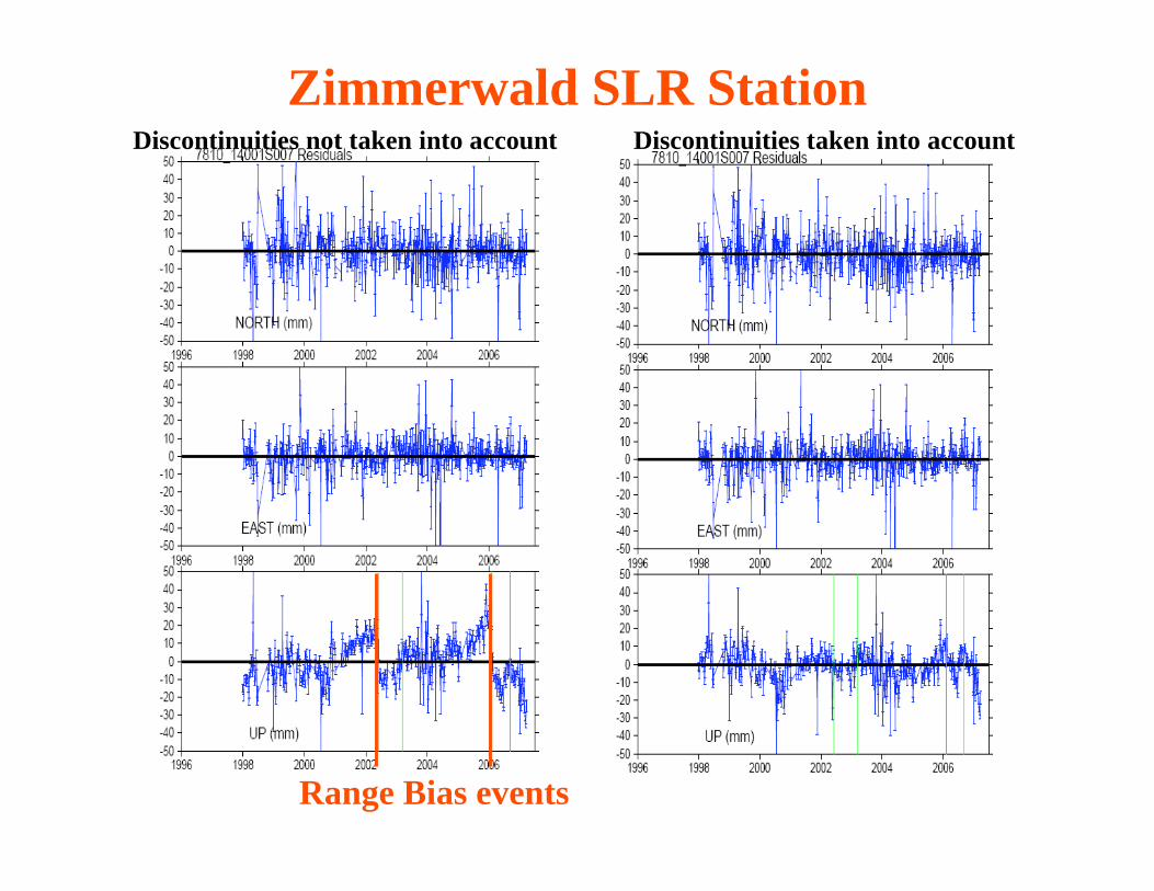
Zimmerwald SLR StationDiscontinuities taken into accountDiscontinuities not taken into account
Range Bias events

Intrinsic ILRS vs OCA scales
ILRS
OCA
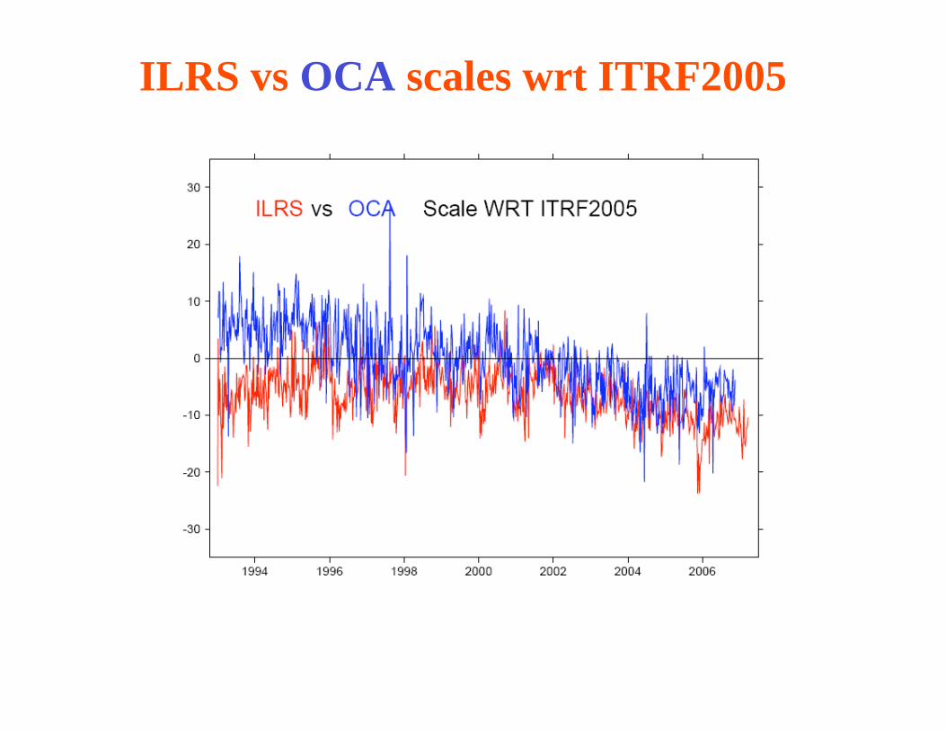
ILRS vs OCA scales wrt ITRF2005

EOP Differences 05 C04 – CATREF

Further Improvements in Understanding CoM
Effects in Laser Ranging Observations
Graham Appleby 1and Toshi Otsubo 2
1: Space Geodesy Facility, Herstmonceux, UK;
2: Hitotsubashi University, Tokyo, Japan
ILRS Spring AWG 14th April 2007, TUW, Wien, Austria
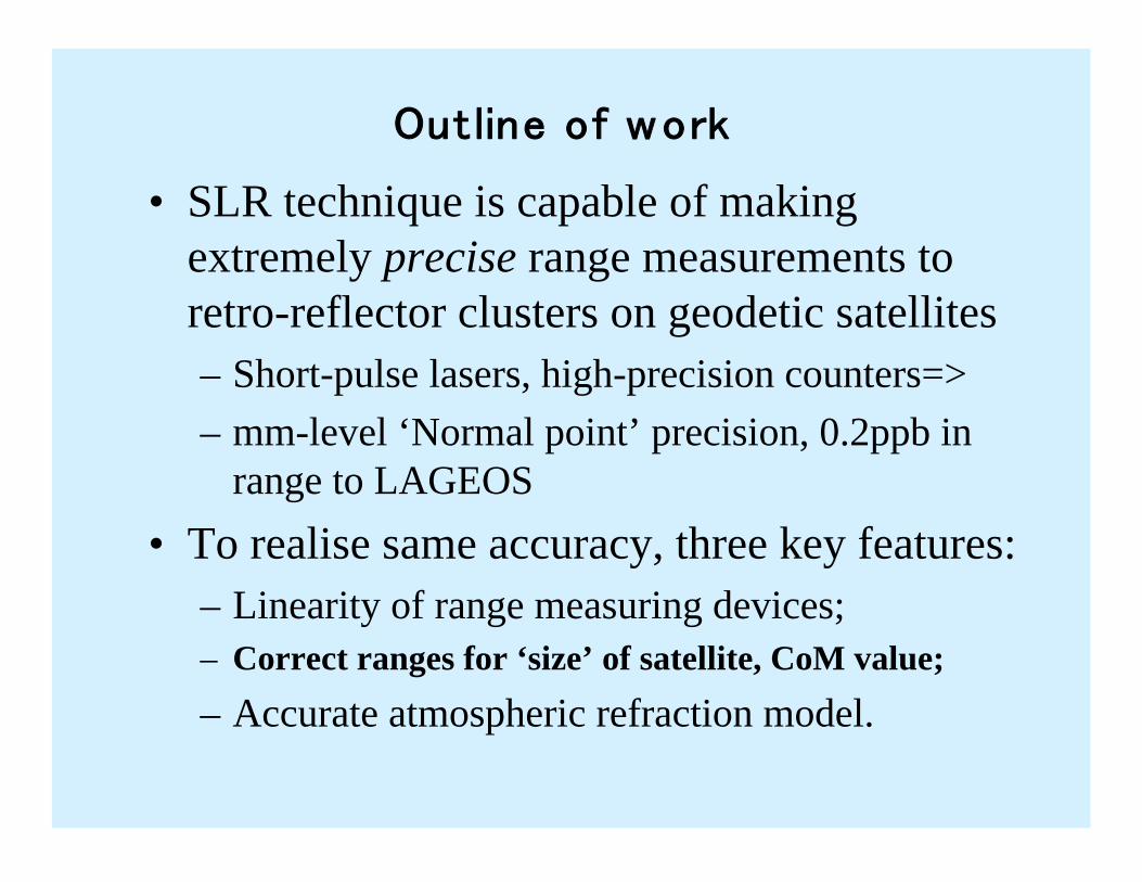
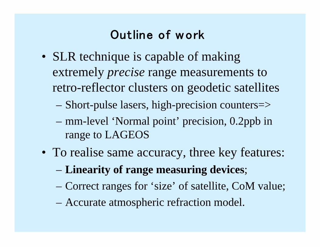
• SLR technique is capable of making
extremely precise range measurements to
retro-reflector clusters on geodetic satellites
– Short-pulse lasers, high-precision counters=>
– mm-level ‘Normal point’ precision, 0.2ppb in
range to LAGEOS
• To realise same accuracy, three key features:
– Linearity of range measuring devices;
– Correct ranges for ‘size’ of satellite, CoM value;
– Accurate atmospheric refraction model.
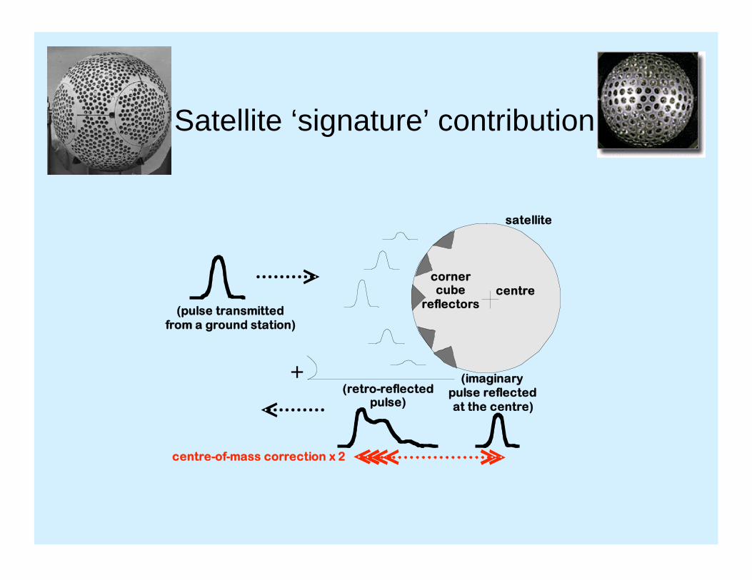
Satellite ‘signature’ contribution
+
satellite
centre
(pulse transmitted
from a ground station)
(retro-reflectedpulse)
corner cube
reflectors
(imaginary
pulse reflected
at the centre)
centre-of-mass correction x 2

Magnitude of effect
• Depending upon the stations’ technologies:
• there is a range of appropriate CoM values;
• for LAGEOS the total range is ~8mm
• Station technology:
• multi-photon returns:
•photomultiplier or first-photon detection
• single photon return
• For a given station, there is a return-energy
dependence too:

Example post-fit range residuals as a function of returns per normal point
(a proxy for return energy variation)
Multi photon Multi photon Single photon
Range bias “-”; Satellite looks
larger
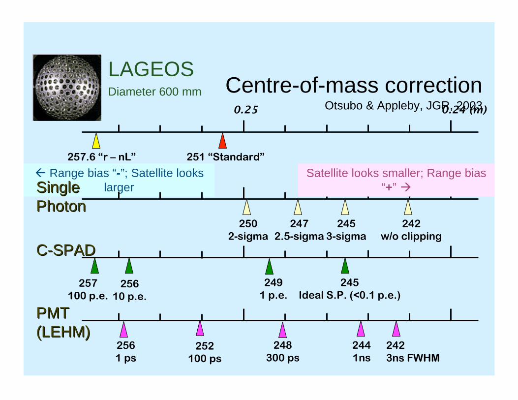
Centre-of-mass correctionOtsubo & Appleby, JGR, 2003
LAGEOSDiameter 600 mm
0.25 0.24 (m)
251 “Standard”257.6 “r – nL”
245
3-sigma
242
w/o clipping
245
Ideal S.P. (<0.1 p.e.)
249
1 p.e.257
100 p.e.256
10 p.e.
256
1 ps252
100 ps
248
300 ps
244
1ns
242
3ns FWHM
SingleSingle
PhotonPhoton
C-SPADC-SPAD
PMTPMT
(LEHM)(LEHM)
250
2-sigma
247
2.5-sigma
Satellite looks smaller; Range bias
“+”
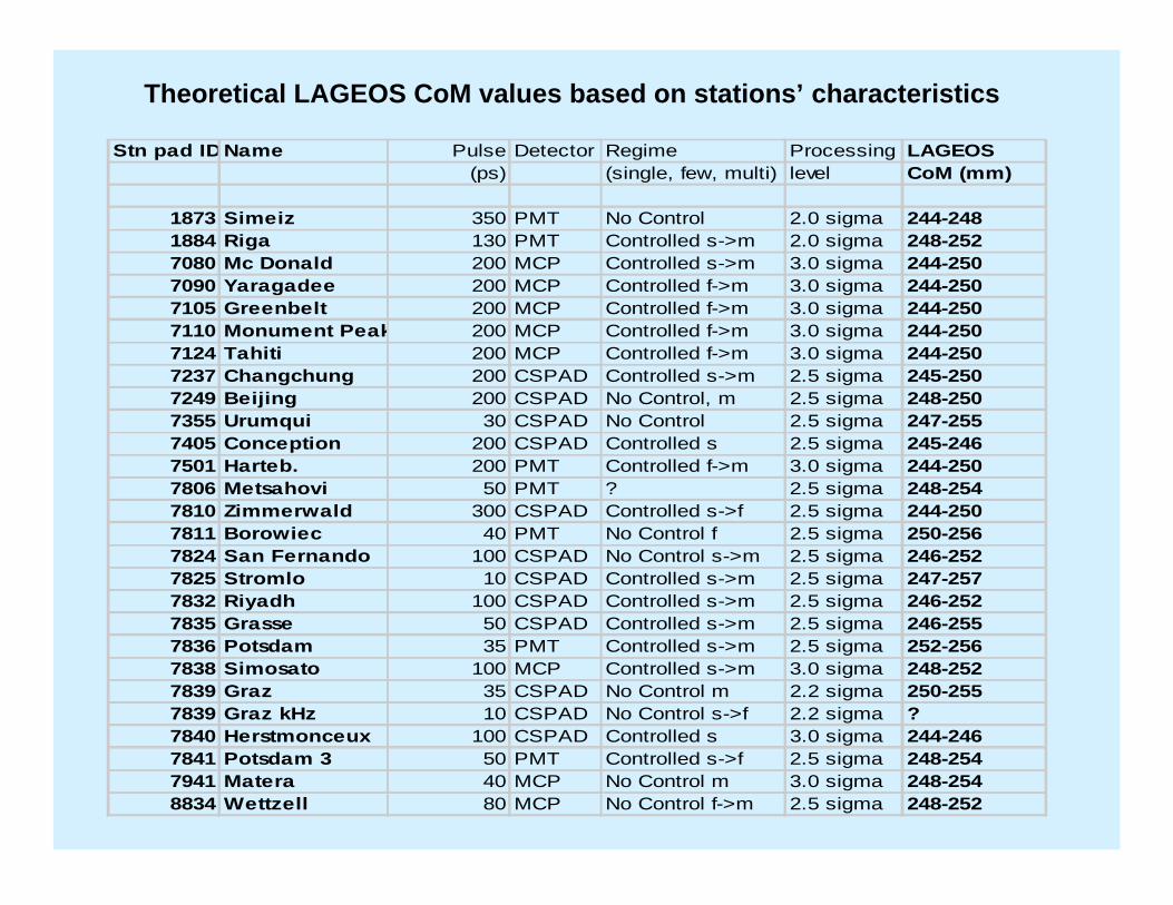
Stn pad IDName Pulse Detector Regime Processing LAGEOS
(ps) (single, few, multi) level CoM (mm)
1873 Simeiz 350 PMT No Control 2.0 sigma 244-248
1884 Riga 130 PMT Controlled s->m 2.0 sigma 248-252
7080 Mc Donald 200 MCP Controlled s->m 3.0 sigma 244-250
7090 Yaragadee 200 MCP Controlled f->m 3.0 sigma 244-250
7105 Greenbelt 200 MCP Controlled f->m 3.0 sigma 244-250
7110 Monument Peak 200 MCP Controlled f->m 3.0 sigma 244-250
7124 Tahiti 200 MCP Controlled f->m 3.0 sigma 244-250
7237 Changchung 200 CSPAD Controlled s->m 2.5 sigma 245-250
7249 Beijing 200 CSPAD No Control, m 2.5 sigma 248-250
7355 Urumqui 30 CSPAD No Control 2.5 sigma 247-255
7405 Conception 200 CSPAD Controlled s 2.5 sigma 245-246
7501 Harteb. 200 PMT Controlled f->m 3.0 sigma 244-250
7806 Metsahovi 50 PMT ? 2.5 sigma 248-254
7810 Zimmerwald 300 CSPAD Controlled s->f 2.5 sigma 244-250
7811 Borowiec 40 PMT No Control f 2.5 sigma 250-256
7824 San Fernando 100 CSPAD No Control s->m 2.5 sigma 246-252
7825 Stromlo 10 CSPAD Controlled s->m 2.5 sigma 247-257
7832 Riyadh 100 CSPAD Controlled s->m 2.5 sigma 246-252
7835 Grasse 50 CSPAD Controlled s->m 2.5 sigma 246-255
7836 Potsdam 35 PMT Controlled s->m 2.5 sigma 252-256
7838 Simosato 100 MCP Controlled s->m 3.0 sigma 248-252
7839 Graz 35 CSPAD No Control m 2.2 sigma 250-255
7839 Graz kHz 10 CSPAD No Control s->f 2.2 sigma ?
7840 Herstmonceux 100 CSPAD Controlled s 3.0 sigma 244-246
7841 Potsdam 3 50 PMT Controlled s->f 2.5 sigma 248-254
7941 Matera 40 MCP No Control m 3.0 sigma 248-254
8834 Wettzell 80 MCP No Control f->m 2.5 sigma 248-252
Theoretical LAGEOS CoM values based on stations’ characteristics

Stn pad IDName Pulse Detector Regime Processing LAGEOS
(ps) (single, few, multi) level CoM (mm)
7110 Monument Peak 200 MCP Controlled f->m 3.0 sigma 244-250
7825 Stromlo 10 CSPAD Controlled s->m 2.5 sigma 247-257
7840 Herstmonceux 100 CSPAD Controlled s 3.0 sigma 244-246
In close-up, for the example stations
We are left with a band of CoM values, the size of which is dependent on
the stations’ technology.
• Single photon systems have tightest band;
• MCP systems’ results appear counter-intuitive in terms of bias wrt energy
regime and do not agree in sign with the theoretical band.
• Answer is strictly to maintain a particular regime during ranging.

Range bias estimates
(LAGEOS1+LAGEOS2) Standard CoM correction 251 mm applied
(M) = Multi photon system, (S) = Single photon system
Station dependence NOT always agrees with prediction at sub-cm region.
… Due to error sources such as timer, calibration, etc?
He
rstm
on
ce
ux (
S)
Gra
z (
S~
M)
Ya
rra
ga
de
e (
M)
Gre
en
be
lt (
M)
Mo
n P
ea
k (
M)
Ha
rte
be
est
(M)
Zim
me
rwa
ld (
S)
Ma
ter
(M)
Mt
Str
om
(M
)
Gra
sse
(M
?)
Ha
lea
ka
l (M
)
5

Conclusion
• With improved
– calibration of counters;
– knowledge of band of appropriate CoM values:
• Can re-estimate stations’ mean bias and
return-energy effects in a full solution to
include
– Constrained RB;
– Coordinates;
– GM

Progress with counter non-linearity effects
Graham Appleby and Philip Gibbs
Space Geodesy Facility, Herstmonceux, UK;
ILRS Spring AWG meeting, 14th April 2007, TUW
• SLR technique is capable of making
extremely precise range measurements to
retro-reflector clusters on geodetic satellites
– Short-pulse lasers, high-precision counters=>
– mm-level ‘Normal point’ precision, 0.2ppb in
range to LAGEOS
• To realise same accuracy, three key features:
– Linearity of range measuring devices;
– Correct ranges for ‘size’ of satellite, CoM value;
– Accurate atmospheric refraction model.


LAGEOS
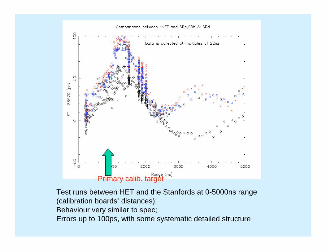
Test runs between HET and the Stanfords at 0-5000ns range
(calibration boards’ distances);
Behaviour very similar to spec;
Errors up to 100ps, with some systematic detailed structure
Primary calib. target


7835GrasseGRSL
Closed sites
7810ZimmerwaldZIML
7231WuhanWUHL
7406San JuanSJUL
7838Simosato, JapanSISL
7824San FernandoSFEL
7836PotsdamPOTL
7841PotsdamPOT3
7820Kunming, ChinaKUNL
1893Katzively, UkraineKTZL
7840HerstmonceuxHERL
7831HelwanHELW
1824KievGLSV
7604BrestBREF
7811BorowieczBORL
7249BeijingBEIL
11 10 1
11 8 meas 3
10 10 0
10 10 0
9 10 -1
8 8 meas 0
10 5 meas 0
10 10 0
19 10 9
10 10 0
8 0 meas 8 meas
10 10 0
16 10 6
20 10 10
9 0 meas 9
22 10 12
Station ID Calibration LAGEOS Total
error error error
Worse-case error estimates (mm)
meas = measured on particular Stanford counter

Summary/outlook
• We emphasize that:
• These stations are a subset of the full ILRS
network, with a high proportion of non-core;
• The counters can be calibrated (ongoing) and
past data reprocessed;
– SGF have started this work, by inviting EUROLAS
stations to send their counters to Hx – one so far.
• Several of the stations have already
upgraded to higher-quality counters.

Graham Appleby, Matt Wilkinson
• Preliminary testing using 1983 -1985 MERIT II NP data (DEOS, DGFI)
• Currently using official ILRS MERIT II LAGEOS NP data via CDDIS
• SATAN package used unchanged wrt operational solutions:
• Decided upon 15-day arcs with 3-day eops (xp, yp, LoD)
•.1cpr terms at 7.5 day intervals, RB for selected stations;
• Solutions completed for 1983 – 1992;
• continuity with date of start of ‘current’ 7-day V6 solutions
• not yet included ILRS-recommended corrections to data
ILRS Spring AWG, 14th April 2007, Vienna
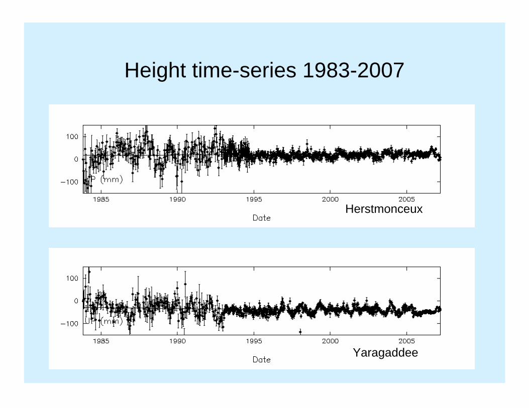
Height time-series 1983-2007
Herstmonceux
Yaragaddee

Stn pad ID Name Pulse Detector Regime Processing LAGEOS(ps) (single, few, multi) level CoM (mm)
1873 Simeiz 350 PMT No Control 2.0 sigma 244-2481884 Riga 130 PMT Controlled s->m 2.0 sigma 248-2527080 Mc Donald 200 MCP Controlled s->m 3.0 sigma 244-2507090 Yaragadee 200 MCP Controlled f->m 3.0 sigma 244-2507105 Greenbelt 200 MCP Controlled f->m 3.0 sigma 244-2507110 Monument Peak 200 MCP Controlled f->m 3.0 sigma 244-2507124 Tahiti 200 MCP Controlled f->m 3.0 sigma 244-2507237 Changchung 200 CSPAD Controlled s->m 2.5 sigma 245-2507249 Beijing 200 CSPAD No Control, m 2.5 sigma 248-2507355 Urumqui 30 CSPAD No Control 2.5 sigma 247-2557405 Conception 200 CSPAD Controlled s 2.5 sigma 245-2467501 Harteb. 200 PMT Controlled f->m 3.0 sigma 244-2507806 Metsahovi 50 PMT ? 2.5 sigma 248-2547810 Zimmerwald 300 CSPAD Controlled s->f 2.5 sigma 244-2507811 Borowiec 40 PMT No Control f 2.5 sigma 250-2567824 San Fernando 100 CSPAD No Control s->m 2.5 sigma 246-2527825 Stromlo 10 CSPAD Controlled s->m 2.5 sigma 247-2577832 Riyadh 100 CSPAD Controlled s->m 2.5 sigma 246-2527835 Grasse 50 CSPAD Controlled s->m 2.5 sigma 246-2557836 Potsdam 35 PMT Controlled s->m 2.5 sigma 252-2567838 Simosato 100 MCP Controlled s->m 3.0 sigma 248-2527839 Graz 35 CSPAD No Control m 2.2 sigma 250-2557839 Graz kHz 10 CSPAD No Control s->f 2.2 sigma ?7840 Herstmonceux 100 CSPAD Controlled s 3.0 sigma 244-2467841 Potsdam 3 50 PMT Controlled s->f 2.5 sigma 248-2547941 Matera 40 MCP No Control m 3.0 sigma 248-2548834 Wettzell 80 MCP No Control f->m 2.5 sigma 248-252
Consolidated Laser Ranging Data Format (CRD)
Version 0.26
R. L. Ricklefs
The University of Texas at Austin / Center for Space Research C. J. Moore
EOS Space Systems Pty. Ltd. For the ILRS Data Formats and Procedures Working Group
28 March 2007
Abstract
Due to recent technology changes, the existing International Laser Ranging Service (ILRS) formats for exchange of laser fullrate, sampled engineering and normal point data are in need of revision. The main technology drivers are the increased use of kilohertz firing-rate lasers which make the fullrate data format cumbersome, and anticipated transponder missions, especially the Lunar Reconnaissance Orbiter (LRO), for which various field sizes are either too small or non-existent. Rather than patching the existing format, a new flexible format encompassing the 3 data types and anticipated target types has been created.
Introduction
The purpose of the Consolidated Laser Ranging Data Format (CRD) is to provide a flexible, extensible format for the ILRS fullrate, sampled engineering, and normal point data. The primary motivations for creating a new format at this time is to allow for transponder data, and to handle high-repetition-rate laser data without unnecessary redundancy. This format is based on the same features found in the ILRS Consolidated Prediction Format (CPF), including separate header and data record types assembled in a building block fashion as required for a particular target.
There are 3 separate sections to the data format: 1) the header section which contains data on the such topics as station, target, and start time; 2) the configuration section containing an expanded version of data previously described by the System Configuration Indicator (SCI) and system CHange Indicator (SCH) fields; and 3) the data section containing laser transmit and receive times, and other highly dynamic information. The data headers are fixed format and similar in content to those of the CPF files. The configuration and data records are free format with spaces between entries. Records can be added as needed for the specific data types and at frequencies commensurate with the data rate. For example, at a 2 kHz ranging rate, meteorological data and pointing angles are commonly read far less frequently than the ranges. Note that 1 way out-bound, 1 way in-bound, and 2 way ranges could all appear within one file. Also note that multiple colors could appear in one file.
Advantages of this format over the current ILRS formats are as follows;
Flexibility. The data files can be simple and compact for kiloHertz ranging or comprehensive for more complex data structures, as appropriate.
The building block structure with multiple record type allows for including and omitting certain

records types as needed by a station or target.
Configuration descriptions are addressed in a more explicit, logical and extensible manner than the current format.
A single integrated format can be used for current and future data and target types.
Multiple color data, multiple ranging modes (transponder one- and two-way ranges) and multiple configurations can be included naturally within a single data file.
The format can be expanded in the future as needs expand without abandoning the entire format.
All data types (full rate, sampled engineering, and normal point) can be managed in a single file if desired, e.g., for archival and reference purposes.
Extensibility to the eXtensible Markup Language (XML) is provided for in the design.
Fields in the Configuration sections are compatible with the SLR Engineering Data File (EDF) format.
When data is converted from an old format to the CRD format, there will be fields (such as skew and kurtosis) that do not exist in the old format. In these cases, unless noted otherwise, numerical fields in the new format should be set to “ -1” to indicated “no information” . Character fields without information should be filled with “na” for “Not Available” .
In the following pages, sections 1 – 3 provide a description and discussion of the specific file sections and record types. Following that, section 4 gives examples of the file structure for various types of data. Section 5 addresses file naming conventions. Section 6 provides some real-world examples of the new format, while section 7 provides web references to formats and “official lists.” Finally, Section 8 provides definitions of abbreviations.

1. Header Records Fields in header records are defined according to the following format specifications (in contrast to data records which will have free format fields that are delimited by white space). Upper and lower case characters are both acceptable: e.g., “H1” or “h1” ; “CRD” or “crd” in H1.
White spaces are allowed (where appropriate) in header record fields since these are fixed format.
1.1. Format Header
The format header describes information relating to the file: e.g. the version of the format used, time of production etc.
1.1.1. Format:
1-2 A2 Record Type (= "H1")
4-6 A3 "CRD" (Consolidated Ranging Data format)
8-9 I2 Format Version
11-14 I4 Year of file production
16-17 I2 Month of file production
19-20 I2 Day of file production
22-23 I2 Hour of file production (UTC)
1.1.2. Notes
There must be one and only one format header record in the file and it must be the first record.
1.2. Station Header
The station header describes information relating to the station or site collecting this laser data.
1.2.1. Format:
1-2 A2 Record Type (= "H2")
4-13 A10 Station name from official list(e.g., "MOB7 ", "MLRS ")
15-18 I4 Crustal Dynamics Project Pad Identifier
20-21 I2 Crustal Dynamics Project 2-digit system number
23-24 I2 Crustal Dynamics Project 2-digit occupancy sequence number
26-27 I2 Station Epoch Time Scale - indicates the time scale reference.
4 = UTC (GPS)
7 = UTC (BIH)
1-2, 5-6, 8-9 = reserved for compatibility with earlier data using obsolete time scales.

10 and above = UTC (Station Time Scales)
1.2.2. Notes
For station-created files, there must be one and only one station header record in the file and it must be the second record. Data centers may combine files.
The “Station Time Scales” option is needed to describe the time scale that accommodates the added precision of fire and return times for transponder ranging. The other time scales are not (yet) good to 1 picosecond, so some other ad hoc time scale must be used. Since the time scale techniques will evolve with time, there are many indicators (10-99) available to describe which time scale is used. In fact, these indicators may be station or experiment dependent.
The Crustal Dynamics Project Pad, site, and occupancy sequence number are often combined into the “CDDIS SOD” found in the official pad and code list mentioned in the introduction to this document.
1.3. Target Header
The target header describes static information relating to the target, whether it is a satellite, lunar or spacecraft target.
1.3.1. Format:
1-2 A2 Record Type (= "H3” )
4-13 A10 Target name from official list(e.g., "Ajisai", "GPS35")
15-22 I8 ILRS Satellite Identifier (Based on COSPAR ID)
24-27 I4 SIC (Satellite Identification Code)
29-36 I8 NORAD ID
38-38 I1 Spacecraft Epoch Time Scale (transponders only)
0 = Not used.
1 = UTC
2 = Spacecraft Time Scale
1.3.2. Notes
There must be at least one target header (and associated child records) in a file but there could possibly be more, e.g. for accumulating normal point data for many targets over a period (e.g. one day) for transmission to data centres. COSPAR ID to ILRS Satellite Identification Algorithm:
COSPAR ID Format: (YYYY-XXXA) YYYY is the four digit year of when the launch vehicle was put in orbit XXX is the sequential launch vehicle number for that year

A is the alpha numeric sequence number within a launch Example: LAGEOS-1 COSPAR ID is 1976-039A Explanation: LAGEOS-1 launch vehicle was placed in orbit in 1976; was the 39th launch in that year; and LAGEOS-1 was the first object injected into orbit from this launch.
ILRS Satellite Identification Format: (YYXXXAA), based on the COSPAR ID
Where YY is the two digit year of when the launch vehicle was put in orbit Where XXX is the sequential launch vehicle number for that year AA is the numeric sequence number within a launch Example: LAGEOS-1 ILRS Satellite ID is 7603901
1.4. Session (Pass) Header
The session/pass header describes information relating to the period over which the data is collected. For normal satellite targets this is generally each pass, but could be associated with pass segments. For geostationary satellites and distant targets, it must be related to time segments as defined by the station. It will be necessary to specify and hence enforce that certain parameters or conditions remain constant or static during a session.
The session header is the place to indicate what type of data records follow – this will enforce data records to be provided in blocks of consistent data rather than allowing sampled engineering, full rate and normal point records to be randomly intermingled.
Hence there must be a Session Header preceding each block of data and there may be more than one Session Header for a given pass or segment if different types of data follow.
1.4.1. Format:
1-2 A2 Record Type (= "H4” )
4-5 I2 Data type
0 = full rate
1 = normal point
2 = sampled engineering
7-10 I4 Starting Year
12-13 I2 Starting Month
15-16 I2 Staring Day
18-19 I2 Starting Hour (UTC)
21-22 I2 Starting Minute (UTC)
24-25 I2 Starting Second (UTC)
27-30 I4 Ending Year (Set ending date and time fields to “0” if not available.)
32-33 I2 Ending Month
35-36 I2 Ending Day

38-39 I2 Ending Hour (UTC)
41-42 I2 Ending Minute (UTC)
44-45 I2 Ending Second (UTC)
47-48 I2 A flag to indicate the data release: 0: first release of data 1: first replacement release of the data, 2: second replacement release, etc
50-50 I1 Tropospheric refraction correction applied indicator
0 = False (not applied)
1 = True (applied)
52-52 I1 Center of mass correction applied indicator
0 = False (not applied)
1 = True (applied)
54-54 I1 Receive amplitude correction applied indicator
0 = False (not applied)
1 = True (applied)
56-56 I1 Station system delay applied indicator
0 = False (not applied)
1 = True (applied)
58-58 I1 Spacecraft system delay applied (transponders) indicator
0 = False (not applied)
1 = True (applied)
60-60 I1 Range type indicator
0 = No ranges (i.e. transmit time only)
1 = 1 way ranging
2 = 2 way ranging
3 = Receive times only
4 = Mixed (for real-time data recording)
Important: If Range type indicator is not set to two-way (2), all corrections must be written as one way quantities. Specifically, this applies to range, calibration, refraction correction, center of mass correction, as well as all RMS and other statistical fields.
1.4.2. Notes
For normal point records, stations generating the file must set the Centre of Mass and Refraction Applied flags to false and provide data consistent with these flags. The format however allows data to be provided where normal point data have these corrections applied e.g. for special purpose users or

for use by data centres themselves.
Ending time may be cumbersome to compute if data is being written directly into the CRD format in real-time. In this case the ending date and time fields may be zero-filled.
1.5. End of Session Footer
1.5.1. Format
1-2 A2 Record Type (= "H8")
1.5.2. Notes
Include even if it is immediately followed by end of file footer.
1.6. End of File Footer
1.6.1. Format
1-2 A2 Record Type (= "H9")
1.6.2. Notes
If an end-of-file footer is missing the implication is that the file has been truncated and has therefore been corrupted. One response could be to request a retransmission of the file.

2. Configuration Records Configuration records will hold static data that represents station specific configuration information used while collecting the data stored in this file. All fields must be separated by spaces, and white spaces are not allowed within record fields. These records are free format and rely on white spaces for parsing. The field types (e.g., I5, F12.5) are suggestions, and should be sized according to the stations’ needs.
While detailed configuration records are strongly encouraged and are a vital part of the CRD format, the minimum requirement is a “C0” record containing the Transmit Wavelength and the System Configuration ID, and the “60” Compatibility Record. The “60” record is not required if records C1-C3 are included, although it may be useful until the format is fully implemented. Record “C4” is always required for transponder data.
The “detail type” field in the configuration records allows for future expansion of the configuration record format. At this time, this field will always have the value “0” .
2.1. System Configuration Record
The system configuration record provides a means for identifying all significant components of a system in operation during collection of the data records contained within this file. This record will be an extensible list of configuration records of components deemed necessary to characterize the system at any given time during which data records are collected.
2.1.1. Format:
A2(1-2) Record Type (= "C0").
A1(3) Detail Type (= "0").
F10.3 Transmit Wavelength (nanometers)
A4 System Configuration id (unique within the file)
A4 Component A configuration id (e.g. detector configuration id)
A4 Component B configuration id (e.g. laser configuration id)
A4 Component C configuration id (e.g. local timing system configuration id)
A4 Component D configuration id (e.g. transponder configuration id)
Repeat as required.
2.1.2. Notes
The use of configuration records replaces the current SCI and SCH (but not the station site log) files. To access information currently contained in the SCH file, one should use the date and time as a key and extract the information from station site log files which should be maintained to provide such data. The SCI file is totally replaced by the records in the current file.
The Transmit Wavelength represent the wavelength of the laser beam as transmitted to the atmosphere and is thus common to many of the station subsystems. Hence it is included explicitly in this record.

One advantage of this is that the association of data records to wavelength used is more direct.
The file must contain at least one Configuration Header. If there are multiple system configurations used when generating the data records contained within the file, then there should be multiple system configuration headers in the file. These should appear after the associated component configuration records have all been defined.
A standard enumerated list of components for many of the configuration fields needs to be maintained. This includes, for example, detector type, laser type, timer. Any input would be appreciated!
2.2. Laser Configuration Record
The file should contain at least one Laser Configuration record. If multiple wavelengths are used or there are significant changes to any of the other parameters within the data sets in the file, then there must be appropriate Laser Configuration records for each wavelength or configuration used.
2.2.1. Format:
A2(1-2) Record Type (= "C1").
A1(3) Detail Type (= "0").
A4 Laser Configuration id (unique within the file)
A10 Laser Type (e.g. “Nd-Yag” )
F10.2 Primary wavelength (nm)
F10.2 Nominal Fire Rate (Hz)
F10.2 Pulse Energy (mJ): record when this fields changes by 10%
F6.1 Pulse Width (ps): record when this fields changes by 10%
F5.2 Beam Divergence (arcsec)
I4 Number of pulses in outgoing semi-train
2.2.2. Notes
Note that the primary wavelength is used here, e.g. use 1064 for a Nd-Yag laser even though only 532 is used.
Most fields are expected to be static for a given laser. Pulse energy and width should trigger the writing of a new record whenever they change by 10%.
2.3. Detector Configuration Record
The file should contain at least one Detector Configuration record. If multiple wavelengths are used or there are significant changes to any of the other parameters within the data sets in the file, then there must be an appropriate Detector Configuration record for each wavelength or configuration used.
2.3.1. Format:
A2(1-2) Record Type (= "C2").
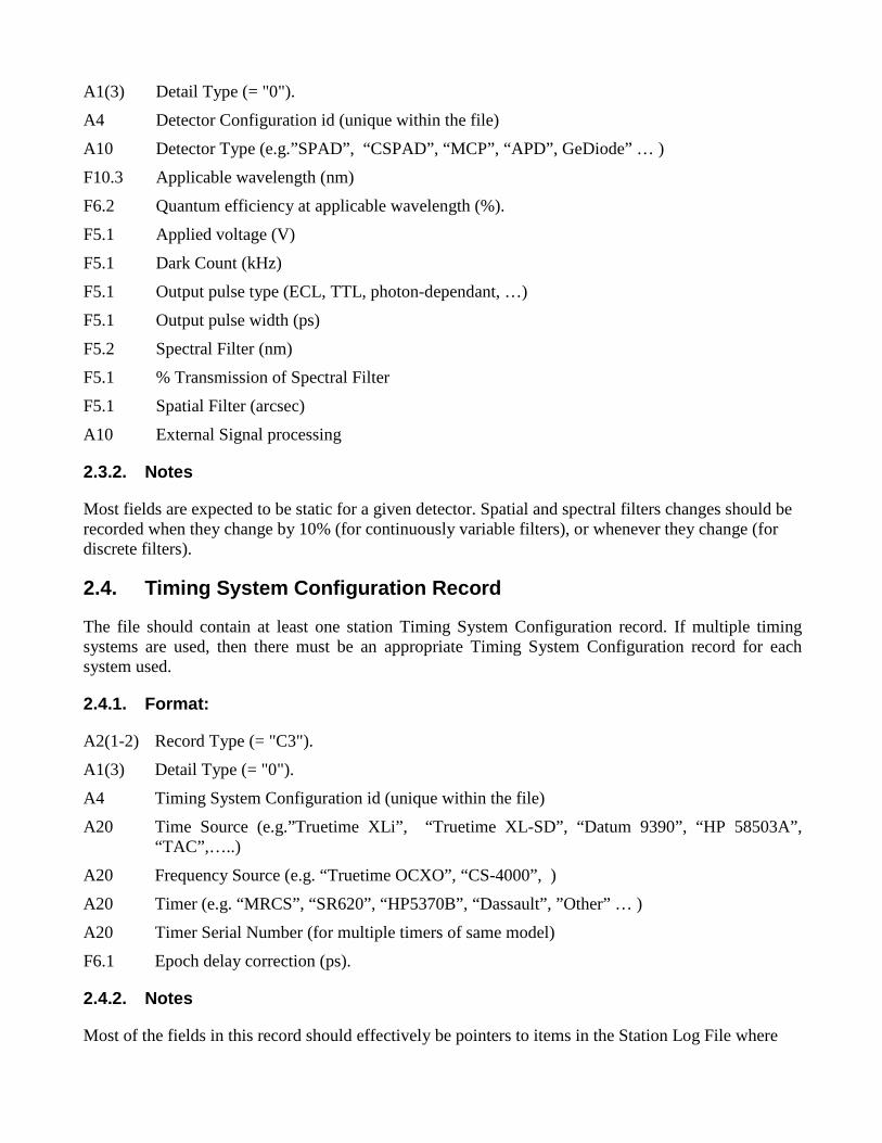
A1(3) Detail Type (= "0").
A4 Detector Configuration id (unique within the file)
A10 Detector Type (e.g.”SPAD”, “CSPAD”, “MCP”, “APD”, GeDiode” … )
F10.3 Applicable wavelength (nm)
F6.2 Quantum efficiency at applicable wavelength (%).
F5.1 Applied voltage (V)
F5.1 Dark Count (kHz)
F5.1 Output pulse type (ECL, TTL, photon-dependant, …)
F5.1 Output pulse width (ps)
F5.2 Spectral Filter (nm)
F5.1 % Transmission of Spectral Filter
F5.1 Spatial Filter (arcsec)
A10 External Signal processing
2.3.2. Notes
Most fields are expected to be static for a given detector. Spatial and spectral filters changes should be recorded when they change by 10% (for continuously variable filters), or whenever they change (for discrete filters).
2.4. Timing System Configuration Record
The file should contain at least one station Timing System Configuration record. If multiple timing systems are used, then there must be an appropriate Timing System Configuration record for each system used.
2.4.1. Format:
A2(1-2) Record Type (= "C3").
A1(3) Detail Type (= "0").
A4 Timing System Configuration id (unique within the file)
A20 Time Source (e.g.”Truetime XLi” , “Truetime XL-SD”, “Datum 9390”, “HP 58503A”, “TAC”,…..)
A20 Frequency Source (e.g. “Truetime OCXO”, “CS-4000”, )
A20 Timer (e.g. “MRCS”, “SR620”, “HP5370B”, “Dassault” , ”Other” … )
A20 Timer Serial Number (for multiple timers of same model)
F6.1 Epoch delay correction (ps).
2.4.2. Notes
Most of the fields in this record should effectively be pointers to items in the Station Log File where

associated static data on each device can be found. The epoch delay correction provides a measure of the propagation delay between the Time Source output and the point at which the timing epochs are registered. For example, in some systems, a 1PPS signal is used to latch second boundaries, However there must be some correction applied for the transmission delay between the source of the 1PPS signal and the timer system.
2.5. Transponder (Clock) Configuration Record
The transponders header describes static information relating to certain transponders
2.5.1. Format:
A2(1-2) Record Type (= "C4").
A1(3) Detail Type (= "0").
A4 Transponder Configuration id (unique within the file)
F20.3 Estimated Station UTC offset (nanoseconds)
F11.2 Estimated Station Oscillator Drift (UTC/station clock) in parts in 1015.
F20.3 Estimated Transponder UTC offset (nanoseconds)
F11.2 Estimated Transponder Oscillator Drift (UTC/spacecraft clock) in parts in 1015
F20.12 Transponder Clock Reference Time. (seconds, scaled or unscaled)
I1 Station offset and drift applied indicator.
0 = False (not applied)
1 = True (applied)
I1 Spacecraft offset and drift applied indicator.
0 = False (not applied)
1 = True (applied)
I1 Spacecraft time simplified
0 = False
1 = True
2.5.2. Notes
Note that standard sense used in all time and frequency metrology must be followed, e.g. local station offset is (UTC – local station). A transponder configuration record is required only if the target contains a transponder or time transfer equipment. To convert from spacecraft master clock units and timescale,
tUTC= tmaster + (tmaster – to) * 10-15 * Oscillator Drift + UTC offset
where to is Transponder Clock Reference Time, the time at which master clock was calibrated against

UTC (somehow), and the UTC offset is (UTC-master) at time to.
For the space craft time simplified mode (used for LRO), to has already been removed from tmaster to allow passing of a much smaller number. The Transponder Clock Reference Time field is filled but only used for reference. The equation then becomes
tUTC= tmaster + (tmaster) * 10-15 * Oscillator Drift + UTC offset.
The conversion for the station clock is analogous.
A new record should be written whenever a field changes value.
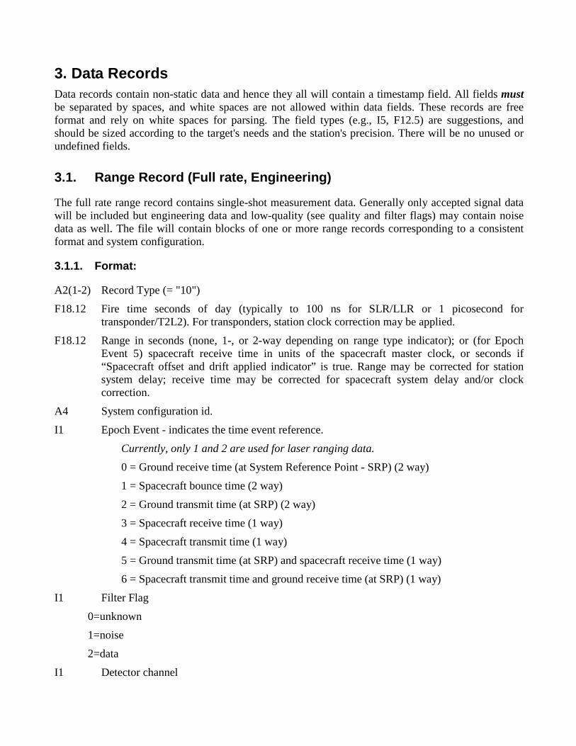
3. Data Records Data records contain non-static data and hence they all will contain a timestamp field. All fields must be separated by spaces, and white spaces are not allowed within data fields. These records are free format and rely on white spaces for parsing. The field types (e.g., I5, F12.5) are suggestions, and should be sized according to the target's needs and the station's precision. There will be no unused or undefined fields.
3.1. Range Record (Full rate, Engineering)
The full rate range record contains single-shot measurement data. Generally only accepted signal data will be included but engineering data and low-quality (see quality and filter flags) may contain noise data as well. The file will contain blocks of one or more range records corresponding to a consistent format and system configuration.
3.1.1. Format:
A2(1-2) Record Type (= "10")
F18.12 Fire time seconds of day (typically to 100 ns for SLR/LLR or 1 picosecond for transponder/T2L2). For transponders, station clock correction may be applied.
F18.12 Range in seconds (none, 1-, or 2-way depending on range type indicator); or (for Epoch Event 5) spacecraft receive time in units of the spacecraft master clock, or seconds if “Spacecraft offset and drift applied indicator” is true. Range may be corrected for station system delay; receive time may be corrected for spacecraft system delay and/or clock correction.
A4 System configuration id.
I1 Epoch Event - indicates the time event reference.
Currently, only 1 and 2 are used for laser ranging data.
0 = Ground receive time (at System Reference Point - SRP) (2 way)
1 = Spacecraft bounce time (2 way)
2 = Ground transmit time (at SRP) (2 way)
3 = Spacecraft receive time (1 way)
4 = Spacecraft transmit time (1 way)
5 = Ground transmit time (at SRP) and spacecraft receive time (1 way)
6 = Spacecraft transmit time and ground receive time (at SRP) (1 way)
I1 Filter Flag
0=unknown
1=noise
2=data
I1 Detector channel

0 = not applicable or “all”
1-4 for quadrant
1-n for many channels
I5 Receive Amplitude - a positive linear scale value.
3.1.2. Notes
Receive signal strength is not in the current normal point format, but is left in this record for compatibility with engineering quick look and full rate data.
Format allows multiple color data to be included in the same file, with separate normal point statistics, etc.
As noted above, transmit time only, receive time only, 1-way, and 2-way ranges etc. can appear in the same file, to accommodate transponders.
Note that station transmit and receive times are nominally with respect to the system reference point (SRP) which will in many cases be the telescope invariant point. This requires a knowledge of both the transmit delay and receive delay, which is critical for transponder ranging. It is less critical for normal satellite (two-way) ranging since errors in distributing the system delay to these components will cancel.
It should be remembered that full rate data should include a swathe of data around the station assessed signal, and assessed noise and signal data be indicated using the filter flag. The noise/data flag should initially be set based on on-site processing.
3.2. Range Record (Normal Point)
The normal point range record contains accepted measurement data formed into normal point bins. The file will contain blocks of one or more range records corresponding to a consistent format and system configuration.
3.2.1. Format:
A2(1-2) Record Type (= "11")
F18.12 Seconds of day (typically to < 100ns for SLR/LLR or <1 ps for transponders). Station clock corrections should be applied for all targets.
F18.12 Range in seconds (none, 1-, or 2-way depending on range type indicator); or (for Epoch Event = 5) spacecraft receive time in units of the spacecraft master clock, or seconds if “Spacecraft offset and drift applied indicator” is true. Range should be corrected for station system delay; receive time may be corrected for spacecraft system delay and/or clock correction.
A4 System configuration id.
I1 Epoch Event - indicates the time event reference.
Currently, only 1 and 2 are used for laser ranging data.
0 = Ground receive time (at SRP) (2 way)
1 = Spacecraft bounce time (2 way)

2 = Ground transmit time (at SRP) (2 way)
3 = Spacecraft receive time (1 way)
4 = Spacecraft transmit time (1 way)
5 = Ground transmit time (at SRP) and spacecraft receive time (1 way)
6 = Spacecraft transmit time and ground receive time (at SRP) (1 way)
I4 Normal point window length (seconds)
I6 Number of raw ranges (after editing) compressed into the normal point.
F9.1 Bin RMS from the mean of raw accepted range values minus the trend function (ps)
F7.3 Bin skew from the mean of raw accepted range values minus the trend function.
F7.3 Bin kurtosis from the mean of raw accepted range values minus the trend function.
F9.1 Bin peak – mean value (ps)
F5.1 Return rate (%) for SLR or signal to noise ratio, in units of 0.1 for LLR.
3.2.2. Notes
Note that station transmit and receive times are nominally with respect to the system reference point (SRP) which will in many cases be the telescope invariant point. This requires a knowledge of both the transmit delay and receive delay, which is critical for transponder ranging. It is less critical for normal satellite (two-way) ranging since errors in distributing the system delay to these components will cancel.
If there are too few data points to assess pass rms, skew, or kurtosis, put “ -1” in the field. It is left to the station’s discretion, subject to ILRS directives, whether to include normal points having few data points.
3.3. Range Supplement Record
The range supplement range record contains optional range data and will be interspersed with range data to which it is associated. If this record is used, then it should be created whenever there is a significant change to one or more fields.
3.3.1. Format:
A2(1-2) Record Type (= "12")
F18.12 Seconds of day.
A4 System configuration id.
F6.1 Tropospheric refraction correction (picoseconds)
F6.4 Target Center of Mass Correction (meters)
F5.2 Neutral Density (ND) filter value
F8.4 Time bias applied (seconds)

3.3.2. Notes
None.
3.4. Meteorological Record
This data record contains a minimal set of meteorological data. At least one record must appear in the data file.
3.4.1. Format:
A2(1-2) Record Type (= "20")
F18.12 Seconds of day (typically to 1 milllisec)
F7.2 Surface Pressure (mbar).
F6.2 Surface Temperature in degrees Kelvin.
F4.0 Relative Humidity at Surface in %
3.4.2. Notes
Meteorological records should only be written when one of the fields changes “significantly” . The criteria should be at least 2 times the least significant bit of the sensor, to prevent noise in the lowest bit from constantly producing new records. In addition the criteria should require new records whenever pressure changes by 0.1 mb, temperature changes by 0.1 K, or humidity changes by 5%.
3.5. Meteorological Supplement Record
This data record contains an (optional) supplement set of meteorological data. A file must contain at least one meteorological record and may contain one or more meteorological supplement records.
3.5.1. Format:
A2(1-2) Record Type (= "21")
F18.12 Seconds of day (typically to 1 milllisec)
F5.1 Wind speed (m/s)
F5.1 Wind direction (degrees azimuth, north is zero)
A4 Precipitation type (“ rain” , “snow”, “ fog” , “ fine” ...TBD)
I3 Visibility (km)
I3 Sky Clarity ( ie zenith extinction coefficient)
I2 Atmospheric seeing (arcsec)
I2 Cloud cover (%)
3.5.2. Notes
Meteorological records should only be written when one of the fields changes “significantly” . The

criteria should be at least 2 times the least significant bit of the sensor, to prevent noise in the lowest bit from constantly producing new records.
Please comment on the choice of fields here!
3.6. Pointing Angles Record
This record contains telescope or beam director pointing (azimuth and elevation) angles, and is optional for normal point data sets. If it is used, the source and nature of this data must be provided.
3.6.1. Format:
A2(1-2) Record Type (= "30")
F18.12 Seconds of day (typically to 1 milllisec)
F8.4 Azimuth in degrees
F8.4 Elevation in degrees
A1 Direction flag
0 = transmit & receive
1 = transmit
2 = receive
A1 Angle Origin Indicator
0 = unknown
1 = computed
2 = commanded (from predictions)
3 = measured (from encoders)
A1 Refraction corrected
0 = False ( in vacuo angles ie angles if no atmosphere is assumed)
1 = True ( apparent angles with refraction included)
3.6.2. Notes
Point angle records should only be written when one of the angles changes “significantly” , which means a change of at least 0.001 degrees.
Is 0.001 degrees too fine?
3.7. Calibration Record
The calibration record contains statistics of accepted calibration measurements. It may be associated with calibrations at the station or target. The file will contain as many calibration records as required, but there must be at least one station calibration record in the file at the station level. Each calibration record is applicable to the subsequent block(s) of range records.

3.7.1. Format:
A2(1-2) Record Type (= "40")
F18.12 Seconds of day (typically to < 100ns for SLR/LLR or <1 ps for transponder ranging). Station clock corrections should be applied for all targets.
I1 Type of data
0=station
1=target (e.g. transponder)
A4 System configuration id
I8 Number of data points recorded (= -1 if no information)
I8 Number of data points used (= -1 if no information)
F7.3 One way target distance (meters, nominal) (= -1 if no information)
F10.1 Calibration System Delay (picoseconds)
F8.1 Calibration Delay Shift - a measure of calibration stability (picoseconds).
F6.1 Root Mean Square (RMS) of raw system delay (ps). If pre- and post- pass calibrations are made, use the mean of the two RMS values, or the RMS of the combined data set.
F7.3 Skew of raw system delay values from the mean. If pre- and post- pass calibrations are made, use the mean of the two skew values, or the skew of the combined data set.
F7.3 Kurtosis of raw system delay values from the mean. If pre- and post- pass calibrations are made, use the mean of the two kurtosis values, or the kurtosis of the combined data set.
F6.1 System delay peak – mean value (ps)
I1 Calibration Type Indicator
0 = Not used or undefined
1 = Nominal (from once off assessment)
2 = External cals
3 = Internal cals
4 = Burst cals
5 = Other
I1 Calibration Shift Type Indicator
0 = Not used or undefined
1 = Nominal (from once off assessment)
2 = Pre – to Post- Shift
3 = Minimum to maximum
4 = Other

3.7.2. Notes
Nominal calibrations are intended for generally low accuracy systems that do not have access to high precision system delay measurements, but rather depend on fairly static and infrequent assessments of system delay. For example, use nominal calibrations for engineering data while a station is being developed, or for other special purposes. I t is expected that one calibration record is expected for a normal point data block, but this record could be used to also provide single shot measurements or indeed averaged blocks (“ normal points” ) of internal calibrations for example.
3.8. Session (Pass) Statistics Record
The session (pass) statistics record contains averaged statistics derived from measurements taken during the session (or over the duration of a pass). The file will contain blocks of one or more range records corresponding to a consistent format. One session statistics record should be associated with each of these data blocks.
3.8.1. Format:
A2(1-2) Record Type (= "50")
A4 System configuration id.
F6.1 Session RMS from the mean of raw, accepted range values minus the trend function (ps).
F7.3 Session Skewness from the mean of raw accepted range values minus the trend function.
F7.3 Session Kurtosis from the mean of raw accepted range values minus the trend function.
F6.1 Session peak – mean value (ps)
I1 Data quality assessment indicator. For SLR and LLR data:
0 = Undefined or no comment.
1 = Clear, easily filtered data, with little or no noise.
2 = Clear data with some noise; filtering is slightly compromised by noise level.
3 = Clear data with a significant amount of noise, or weak data with little noise. Data are certainly present, but filtering is difficult.
4 = Un-clear data; data appear marginally to be present, but are very difficult to separate from noise during filtering. Signal to noise ratio can be less than 1:1.
5 = No data apparent.
3.8.2. Notes
This record is only required in combination with a number of normal point records. It is optional with full rate or engineering data records.

3.9. Compatibility Record
This record is provided primarily to allow reformatting of old data from the ILRS normal point and full-rate data to this format, without losing existing data.
3.9.1. Format:
A2(1-2) Record Type (= "60").
A4 System configuration id.
I1 System CHange indicator (SCH)
A flag to increment for every major change to the system (hardware or software). After the value '9' return to '0', and then continue incrementing. The station and data centers should keep a log in a standard format of the value used, the date of the change, and a description of the change.
I1 System Configuration Indicator (SCI)
A flag used to indicate alternative modes of operation for a system (e.g., choice of alternative timers or detectors, or use of a different mode of operation for high satellites). Each value of the flag indicates a particular configuration, which is described in a log file held at the station and at the data centers. If only a single configuration is used then use a fixed value. If a new configuration is introduced then use the next higher flag value. If value exceeds '9' then return to '0', overwriting a previous configuration flag (it is not likely that a station will have 10 current possible configurations).
3.9.2. Notes
None
3.10. User Defined Record
This record is provided to allow special interest users or groups to add non-standard data records. Other uses must be able to ignore such records (if they exist in a file) without any impact. Record types outside this range will be reserved for future standard format use.
3.10.1. Format:
A2(1-2) Record Type (= "9X", X = 0…9).
3-80 User defined format
3.10.2. Notes
None
3.11. Comment Record
Comment records are optional, and allow users to insert comments or notes as deemed necessary and appropriate.

3.11.1. Format:
A2(1-2) Record Type (= "00").
A80 Free format ASCII comments (terminated by an end-of-line character).
3.11.2. Notes
To ensure line lengths do not become excessive, a limit of 80 characters is set. Lines exceeding this limit may be truncated. Multiple comment lines are encouraged. Comment lines can occur anywhere within a file.

4. Record Structure The records as defined should have the potential for storing a quite complex mix of data types while maintaining data integrity. The format must support a consistent, unambiguous data set that can be readily parsed for currently used and expected data sets, and for data sets that are possible in the future. The data stored in a CRD file should be capable of being stored in a normalized database and/or expressed in the XML language. The definitions of the records have kept this in mind.
It is important that, unless totally unavoidable, data fields are not repeated as this has the potential for undermining the requirement for unambiguous and consistent data. It is also efficient in terms of file sizing and storage.
Consider a number of cases. The first is simple case where the station is performing basic satellite tracking and is creating full rate and normal point files. In practice, this will probably represent the majority of files most of the time, at least for the present.
A more complex case where a station is performing two-colour ranging and wants to store both full rate and normal point data in the one file, or when a site is publishing full rate data from experiments in time transfer using target transponders.
4.1. Case 1
Two files containing full rate for one target and normal point data for one period (for example, one day). This is typical for existing normal point (.qld) and fullrate (.fr) files being generated at many stations. (Comment records are not considered here.)
Full rate file for 1 target, single system configuration.
Format Header
Station Header
Target Header
Laser Configuration Record
Detector Configuration Record
Timing System Configuration Record
System Configuration Record
Calibration Record
Session Header
Calibration Record (if required)
Pointing Record / Mets Record
Data Record (Full rate) (repeated)
Calibration Record / Pointing Record / Mets Record (as required)
Data Record (Full rate) (repeated)
Calibration Record (if required)

Pointing Record / Mets Record
End Of Session Header
Session Header
Calibration Record (if required)
Pointing Record / Mets Record
Data Record (Full rate) (repeated)
Calibration Record / Pointing Record / Mets Record (as required)
Data Record (Full rate) (repeated)
Calibration Record (if required)
Pointing Record / Mets Record
End of session Header
…… (as many session as required)
End of file header
Normal point file for many targets, single system configuration.
Format Header
Station Header
Laser Configuration Record
Detector Configuration Record
Timing System Configuration Record
System Configuration Record
Calibration Record
Target Header
Session Header
Calibration Record (if required)
Mets Record
Data record (normal point) ( repeated )
Mets Record
Data record (normal point) ( repeated )
Mets Record
Pass Record
End of session header
….. other sessions for this target as required
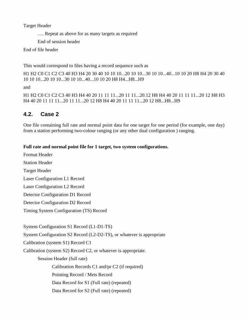
Target Header
…. Repeat as above for as many targets as required
End of session header
End of file header
This would correspond to files having a record sequence such as
H1 H2 C0 C1 C2 C3 40 H3 H4 20 30 40 10 10 10...20 10 10...30 10 10...40...10 10 20 H8 H4 20 30 40 10 10 10...20 10 10...30 10 10...40...10 10 20 H8 H4...H8...H9
and
H1 H2 C0 C1 C2 C3 40 H3 H4 40 20 11 11 11...20 11 11...20.12 H8 H4 40 20 11 11 11...20 12 H8 H3 H4 40 20 11 11 11...20 11 11...20 12 H8 H4 40 20 11 11 11...20 12 H8...H8...H9
4.2. Case 2
One file containing full rate and normal point data for one target for one period (for example, one day) from a station performing two-colour ranging (or any other dual configuration ) ranging.
Full rate and normal point file for 1 target, two system configurations.
Format Header
Station Header
Target Header
Laser Configuration L1 Record
Laser Configuration L2 Record
Detector Configuration D1 Record
Detector Configuration D2 Record
Timing System Configuration (TS) Record
System Configuration S1 Record (L1-D1-TS)
System Configuration S2 Record (L2-D2-TS), or whatever is appropriate
Calibration (system S1) Record C1
Calibration (system S2) Record C2, or whatever is appropriate.
Session Header (full rate)
Calibration Records C1 and/pr C2 (if required)
Pointing Record / Mets Record
Data Record for S1 (Full rate) (repeated)
Data Record for S2 (Full rate) (repeated)

Calibration Records / Pointing Record / Mets Record (as required)
Data Records for S1 (Full rate) (repeated)
Data Records for S2 (Full rate) (repeated)
Calibration Records (if required)
Pointing Record / Mets Record
End of session Header
Session Header (normal point)
Mets Record
Data Record for S1 and/or S2(normal point) (repeated)
Mets Record
Data Record for S1 and/or S2 (normal point) (repeated)
Mets Record
End of session Header
Session Header (full rate)
…. (Repeat as above for as many sessions as required)
End of session Header
End of file header
This would correspond to files having a record sequence such as
H1 H2 H3 C0 C0 C1 C1 C2 C2 C3 H4 20 30 40 40 10 10 10 10...20 10 10 10 10...30 10 10 10 10...40...10 10 20 H8 H4 20 11 11 11 11...20 11 11 11 11...11 11 11 11...11 11 20 H8 H4 20 30 40 40 10 10 10 10...20 10 10 10 10...30 10 10 10 10...40...10 10 20 H8 H4 20 11 11 11 11...20 11 11 11 11...11 11 11 11...11 11 20 H8…H8 H9.
4.3. Case 3
One file containing full rate data for one target from a station performing experiments in time transfer via a transponder in association with another station.
Full rate 1 target, two system configurations.
Format Header
Station Header
Target Header
Laser Configuration Record
Detector Configuration Record
Timing System Configuration Record

Transponder Configuration Record
System Configuration Record
Calibration Record (Site)
Calibration Record (Target)
Session Header (full rate)
Calibration Record (Site) (if required)
Calibration Record (Target) (if required)
Pointing Record / Mets Record
Data Record (Full rate, range and transmit epoch) (repeated)
Data Record (Full rate, receive epoch only) (repeated)
Pointing Record / Mets Record
End of session Header
End of file header
4.4. Case 4
In this case, several fullrate or normalpoint sessions from one station are sent in a single file from the station to a data center. There are two ways of doing this:
4.4.1. Preferred method
H1 H2 H3 H4 ... H8
H3 H4 ... H8
...
H3 H4 ... H8 H9
This ordering is more hierarchical and is more compatible with parsing into XML.
4.4.2. Acceptable, but not preferred, method
H1 H2 H3 H4 ... H8
H1 H2 H3 H4 ... H8
...
H1 H2 H3 H4 ... H8 H9
This ordering is syntactically correct, and may be easier to implement when converting data in the old format to CRD.

5. File Naming Since the proposed data format is so flexible and a file could contain many data types and cover any number of periods, file naming becomes a real issue. Therefore there must be a number of conventions adopted. Proposed conventions are:
1. File names and file naming conventions do not form the basis for file processing except for files that have well defined and specific file extensions (such as .Z for extraction purposes).
2. File names ending in “ .NPT”, “ .FRD”, or “ .QLK” contain single data types, but possibly multiple satellites and stations.
3. File names ending in “ .CRD” may contain multiple data types.
4. Files are delivered to specific file repositories in which it has been agreed and understood that certain file operations will be performed. Hence the onus is on the supplier to provide the appropriate type of file to the repository.
5. Published files will always have a unique file name. (Pertains to station naming conventions.)
6. Release versions are maintained within the data file headers. Data center files names will not include release information.
7. File processing will require files to be opened and parsed to determine what operations, if any, are to be performed.
5.1. Station Naming Convention
This naming convention is for use with files transmitted from the station to the dataTHIS CONVENTION IS UNDERGOING REVISION
date[_station-name][_target-name][_mjd][_type][_other].crd
where the [] indicates optional fields and
- Date is the date and time of production/transmission in format yyyymmddhhmmss.
- Station-name is the station name with no white spaces, if the file contains only data from that station,
- Target-name is the target name with no white spaces, if the file contains only data for that target,
- Mjd is the integral modified julian date if the file contains data for that one day only,
- Type is one of the following if the file contains only data of that type,
“np” for normal point data,
“ fr” for full rate data, and
“ql” for engineering, quick look data.
- Other is a suitable string without white spaces, if none of these options are appropriate.
Files may contain the “ .Z” , “ .z” , or “ .zip” extension indicating a particular type of file compression.

5.2. Data Center Naming Convention
Data centers (e.g. CDDIS and EDC) will use these file names at their ftp and web sites. These are the file names the users will see when retrieving data for their analysis work. Each file will contain only one type of data.
satname_yyyymmddhh.typ (hourly) satname_yyyymmdd.typ (daily) satname_yyyymm.typ (monthly) satname_yyyy.typ
where - satname is from a standard ILRS list of spacecrafts; - yyyy is the 4-digit year, - mm is the 2-digit month, - dd is the 2-digit day, - hh is the 2-digit hour, and
- typ is frd – full-rate data, qlk – engineering sampled engineering data, npt – normal point data.
Examples: starlette_2006091011.frd lro_200810.npt Files may contain the “ .Z” or “ .z” extension indicating file compression.
5.3.

6. Sample Files This section includes passes and samples of passes represented in the CRD format. Note that record lengths were kept short by using “%.xf” c language formats for most floating point fields.
6.1. Fullrate
Filename: lageos2_7080_crd_20061113152300_01.frd H1 CRD 1 2007 3 20 14 H2 MLRS 7080 24 19 4 H3 LAGEOS2 9207002 5986 22195 0 H4 0 2006 11 13 15 23 52 2006 11 13 15 45 35 1 1 1 1 0 0 2 C0 0 532.000 std1 60 std1 5 2 10 55432.0414338 0.047960587856 std1 2 0 0 0 12 55432.0414338 std1 20735.0 1601.0000 0.00 0.0000 20 55432.0414338 801.80 28.21 39 30 55432.0414338 297.2990 38.6340 0 2 1 40 55432.0414338 0 std1 -1 -1 0.000 -913.0 0.0 56.0 -1.000 -1.000 -1.0 3 3 10 55435.6429746 0.047926839980 std1 2 0 0 0 12 55435.6429746 std1 20697.0 1601.0000 0.00 0.0000 30 55435.6429746 297.4480 38.7190 0 2 1 ... 10 56735.8021609 0.046094881873 std1 2 0 0 0 12 56735.8021609 std1 18092.0 1601.0000 0.00 0.0000 30 56735.8021609 15.2330 45.7100 0 2 1 H8 H9
6.2. Normal Point
File name: lageos2_7080_crd_20061113152300_01.npt H1 CRD 1 2007 3 20 14
H2 MLRS 7080 24 19 4
H3 LAGEOS2 9207002 5986 22195 0
H4 1 2006 11 13 15 25 4 2006 11 13 15 44 40 0 0 0 0 1 0 2
C0 0 532.000 std1
60 std1 5 2
11 55504.9728030 0.047379676080 std1 2 120 18 94.0 -1.000 -1.000 -1.0 0.0
20 55504.9728030 801.80 282.10 39

40 55504.9728030 0 std1 -1 -1 0.000 -913.0 0.0 56.0 -1.000 -1.000 -1.0 3 3
11 55988.9809589 0.044893190432 std1 2 120 19 83.0 -1.000 -1.000 -1.0 0.0
20 55988.9809589 801.50 282.80 39
11 56141.8467215 0.044635017248 std1 2 120 28 66.0 -1.000 -1.000 -1.0 0.0
11 56223.2817254 0.044605221903 std1 2 120 25 87.0 -1.000 -1.000 -1.0 0.0
20 56223.2817254 801.50 282.60 39
11 56373.5463612 0.044746486398 std1 2 120 25 78.0 -1.000 -1.000 -1.0 0.0
20 56373.5463612 801.50 282.10 39
11 56439.9749454 0.044889147842 std1 2 120 25 99.0 -1.000 -1.000 -1.0 0.0
11 56565.2288146 0.045288773098 std1 2 120 25 92.0 -1.000 -1.000 -1.0 0.0
11 56680.8785419 0.045804632570 std1 2 120 10 55.0 -1.000 -1.000 -1.0 0.0
20 56680.8785419 801.50 282.00 39
50 std1 86.0 -1.000 -1.000 -1.0 0
H8
H9
6.3. Sample Engineering (Quicklook)
File name: lageos2_7080_crd_20061113152300_01.qlk H1 CRD 1 2007 3 20 14
H2 MLRS 7080 24 19 4
H3 LAGEOS2 9207002 5986 22195 0
H4 2 2006 11 13 15 24 17 2006 11 13 15 44 59 0 0 0 0 0 0 2
C0 0 532.000 std1
60 std1 5 2
10 55457.0521861 0.047753624332 std1 2 0 0 0
20 55457.0521861 801.80 282.10 39
30 55457.0521861 298.3470 39.2230 0 0 0
10 55482.4631214 0.047552685849 std1 2 0 0 0
30 55482.4631214 299.4370 39.8100 0 0 0
...
10 56589.0390552 0.045383653062 std1 2 0 0 0
20 56589.0390552 801.50 282.00 39
30 56589.0390552 6.7380 47.9120 0 0 0
10 56623.4538362 0.045531247776 std1 2 0 0 0
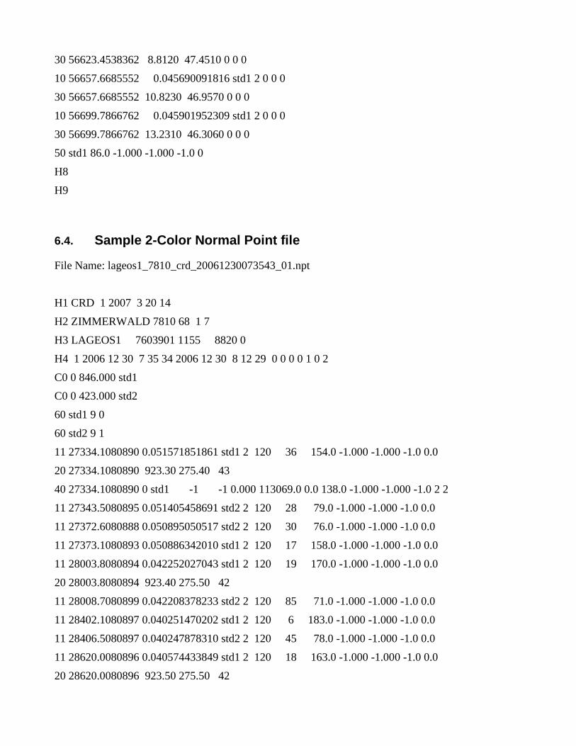
30 56623.4538362 8.8120 47.4510 0 0 0
10 56657.6685552 0.045690091816 std1 2 0 0 0
30 56657.6685552 10.8230 46.9570 0 0 0
10 56699.7866762 0.045901952309 std1 2 0 0 0
30 56699.7866762 13.2310 46.3060 0 0 0
50 std1 86.0 -1.000 -1.000 -1.0 0
H8
H9
6.4. Sample 2-Color Normal Point file
File Name: lageos1_7810_crd_20061230073543_01.npt
H1 CRD 1 2007 3 20 14
H2 ZIMMERWALD 7810 68 1 7
H3 LAGEOS1 7603901 1155 8820 0
H4 1 2006 12 30 7 35 34 2006 12 30 8 12 29 0 0 0 0 1 0 2
C0 0 846.000 std1
C0 0 423.000 std2
60 std1 9 0
60 std2 9 1
11 27334.1080890 0.051571851861 std1 2 120 36 154.0 -1.000 -1.000 -1.0 0.0
20 27334.1080890 923.30 275.40 43
40 27334.1080890 0 std1 -1 -1 0.000 113069.0 0.0 138.0 -1.000 -1.000 -1.0 2 2
11 27343.5080895 0.051405458691 std2 2 120 28 79.0 -1.000 -1.000 -1.0 0.0
11 27372.6080888 0.050895050517 std2 2 120 30 76.0 -1.000 -1.000 -1.0 0.0
11 27373.1080893 0.050886342010 std1 2 120 17 158.0 -1.000 -1.000 -1.0 0.0
11 28003.8080894 0.042252027043 std1 2 120 19 170.0 -1.000 -1.000 -1.0 0.0
20 28003.8080894 923.40 275.50 42
11 28008.7080899 0.042208378233 std2 2 120 85 71.0 -1.000 -1.000 -1.0 0.0
11 28402.1080897 0.040251470202 std1 2 120 6 183.0 -1.000 -1.000 -1.0 0.0
11 28406.5080897 0.040247878310 std2 2 120 45 78.0 -1.000 -1.000 -1.0 0.0
11 28620.0080896 0.040574433849 std1 2 120 18 163.0 -1.000 -1.000 -1.0 0.0
20 28620.0080896 923.50 275.50 42
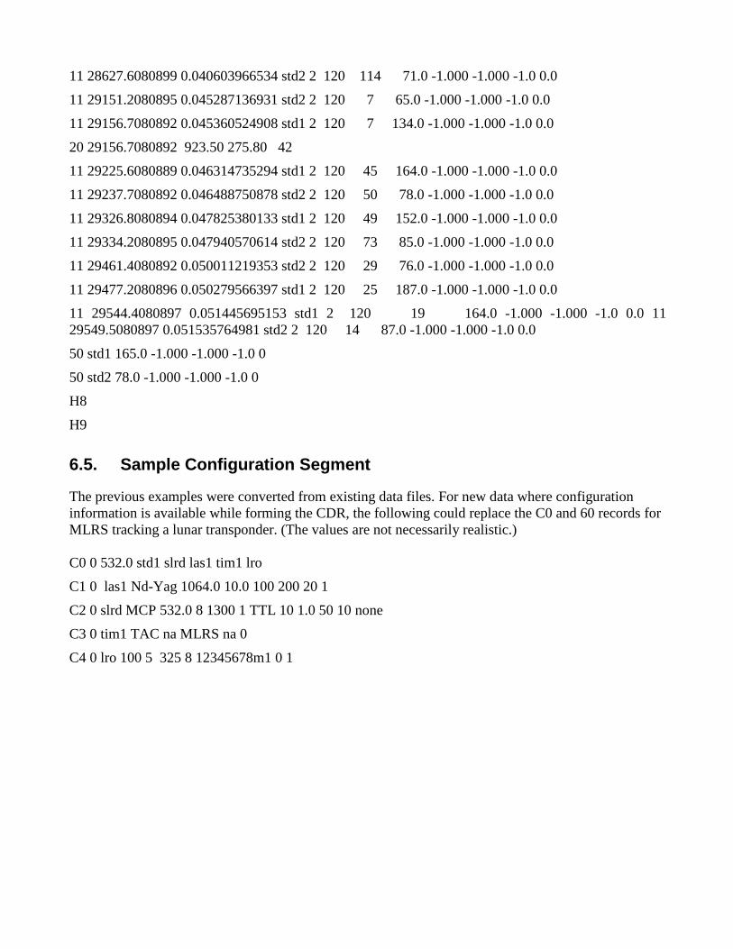
11 28627.6080899 0.040603966534 std2 2 120 114 71.0 -1.000 -1.000 -1.0 0.0
11 29151.2080895 0.045287136931 std2 2 120 7 65.0 -1.000 -1.000 -1.0 0.0
11 29156.7080892 0.045360524908 std1 2 120 7 134.0 -1.000 -1.000 -1.0 0.0
20 29156.7080892 923.50 275.80 42
11 29225.6080889 0.046314735294 std1 2 120 45 164.0 -1.000 -1.000 -1.0 0.0
11 29237.7080892 0.046488750878 std2 2 120 50 78.0 -1.000 -1.000 -1.0 0.0
11 29326.8080894 0.047825380133 std1 2 120 49 152.0 -1.000 -1.000 -1.0 0.0
11 29334.2080895 0.047940570614 std2 2 120 73 85.0 -1.000 -1.000 -1.0 0.0
11 29461.4080892 0.050011219353 std2 2 120 29 76.0 -1.000 -1.000 -1.0 0.0
11 29477.2080896 0.050279566397 std1 2 120 25 187.0 -1.000 -1.000 -1.0 0.0
11 29544.4080897 0.051445695153 std1 2 120 19 164.0 -1.000 -1.000 -1.0 0.0 11 29549.5080897 0.051535764981 std2 2 120 14 87.0 -1.000 -1.000 -1.0 0.0
50 std1 165.0 -1.000 -1.000 -1.0 0
50 std2 78.0 -1.000 -1.000 -1.0 0
H8
H9
6.5. Sample Configuration Segment
The previous examples were converted from existing data files. For new data where configuration information is available while forming the CDR, the following could replace the C0 and 60 records for MLRS tracking a lunar transponder. (The values are not necessarily realistic.) C0 0 532.0 std1 slrd las1 tim1 lro
C1 0 las1 Nd-Yag 1064.0 10.0 100 200 20 1
C2 0 slrd MCP 532.0 8 1300 1 TTL 10 1.0 50 10 none
C3 0 tim1 TAC na MLRS na 0
C4 0 lro 100 5 325 8 12345678m1 0 1

7. Resources The official list of satellite names and numerical identifiers can be found at:
http://ilrs.gsfc.nasa.gov/products_formats_procedures/satellite_names.html . The satellite numerical identifiers can be found at:
http://ilrs.gsfc.nasa.gov/satellite_missions/list_of_satellites/index.html .
The official list of station names can be found at:
TBD .
The official list of station monument (pad) numbers and codes can be found at:
http://ilrs.gsfc.nasa.gov/stations/sitelist/index.html .
Find information on site files at:
http://ilrs.gsfc.nasa.gov/stations/site_procedures/site_logs/site_log_procedure.html .
Find formats for the pre-CRD data formats at:
http://ilrs.gsfc.nasa.gov/products_formats_procedures/normal_point/np_format.html
and
http://ilrs.gsfc.nasa.gov/products_formats_procedures/fullrate/fr_format_v3.html .
The latest official version of this document can be found at:
http://ilrs.gsfc.nasa.gov/products_formats_procedures/crd.html .

8. Common Abbreviations
CRD Consolidated laser Ranging Data Format
COSPAR Committee on Space Research, a Committee of ICSU, the International Council for Science.
CPF Consolidated laser ranging Prediction Format
ILRS International Laser Ranging Service
LLR Lunar Laser Ranging
LRO Lunar Reconnaissance Orbiter
ND Neutral Density, which describes opacity of a broad band optical filter.
NORAD The North American Aerospace Defense Command
ns nanoseconds
ps picoseconds
RMS Root Mean Square. Same as standard deviation.
SLR Satellite Laser Ranging
SCH Station Change Indicator
SCI Station Configuration Indicator
SIC Satellite Identification Code, a 4 digit satellite descriptor.
SRP System Reference Point, usually described as the first non-moving point in the telescope light path.
UTC Coordinated Universal Time, formerly known as Greenwich Mean Time (GMT).
XML eXtensible Markup Language.

MISSION NAME SP3c Code ILRS SI NORAD # Altitude [km] Inclination °
General group
TOPEX/Poseidon L01 9205201 22076 1350 66 OffGPS-MET L02 9501703 23547 740 69.9 OffGFO-1 L03 9800701 25157 800 108Ørsted L04 9900802 25635 630 96.1 OffSUNSAT L05 9900803 25636 400 93 OffCHAMP L06 0003902 26405 474 87SAC-C L07 0007502 26620 682 98.2 OffJason-1 L08 0105501 26997 1336 66GRACE-A L09 0201201 27391 485-500 89GRACE-B L10 0201202 27392 485-500 89ICESat L11 0300201 27642 600 94CryoSat L12 -- -- -- -- --TerraSAR-X L13 514 97.4METOP-2 L14 0604401 29499 817 98.7GOCE L15 250 96.5Beacon-C L16 6503201 1328 927 41DIADEME-1C L17 6701101 2674 545 40 OffDIADEME-1D L18 6701401 2680 585 40 OffIRS-P5 (CARTOSAT-1) L19 0501701 28649 620 97.9
L20L20COSMIC-1 (FM-1) L21 0601101 29047 815 72.0COSMIC-2 (FM-2) L22 0601102 29048 815 72.0COSMIC-3 (FM-3) L23 0601103 29049 815 72.0COSMIC-4 (FM-4) L24 0601104 29050 815 72.0COSMIC-5 (FM-5) L25 0601105 29051 815 72.0COSMIC-6 (FM-6) L26 0601106 29052 815 72.0
L27L27GEOS-3 L28 7502701 7734 841 115 OffSeasat L29 7806401 10967 805 108 OffGEOSAT L30 8502101 15595 760 x 817 108.1 OffERS-1 L31 9105001 21574 780 99 OffERS-2 L32 9502101 23560 800 99Envisat L33 0200901 27386 800 98Meteor-3M L34 0105601 27001 1000 99.6 Off
L35-L49L35-L49Ajisai L50 8606101 16908 1485 50LAGEOS-1 L51 7603901 8820 5850 110LAGEOS-2 L52 9207002 22195 5625 53Etalon-1 L53 8900103 19751 19105 65Etalon-2 L54 8903903 20026 19135 65Starlette L55 7501001 7646 815x1100 50Stella L56 9306102 22824 815 99GFZ-1 L57 8601795 23558 385 52 OffWESTPAC L58 9804301 25394 835 98 OffLarets L59 0304206 27944 691 98.2
L60-L90L60-L90SPOT-2 L91 9000501 20436 786 98.7SPOT-3 L92 9306101 22823 832 98.7 OffSPOT-4 L93 9801701 25260 802 98.7SPOT-5 L94 0202101 27421 777 98.7
L95-L99L95-L99
GPS group*
GPS-35 G05 9305401 22779 20195 54GPS-36 G06 9401601 23027 20030 55
GLONASS group*
GLONASS-87 R03 0105302 26988 19140 65GLONASS-86 R06 0105303 26989 19140 65 OffGLONASS-95 R07 0405302 28509 19140 65GLONASS-89 R22 0206001 27617 19140 65GLONASS-99 R24 0505002 28916 19140 65
GALILEO group*
GIOVE-A E01 0505101 28922 23916 56
Tracking Status
Spaceraft ID Correspondence Table for Orbit Exchange Files (SP3c)
International Association for Geodesy (IAG) Inter-Service Document
Version 2007.02.01
Procedure for a request of code assignment: see note at bottom of tableProcedure for a request of code assignment: see note at bottom of table

LEGEND
Codes in RED BOLDRED BOLD:
SP3c Code: A letter and a 2-digit number assigned by the list-keeper in consultation with the IERS Services
L For all s/c other than GPS, GLONASS, and GALILEO
G For GPS s/c
R For GLONASS s/c
E For GALILEO s/c
ILRS Satellite ID†: YYXXXAA where:
YY: last two digits of launch-vehicle launch year,XXX: launch vehicle number in year YY, andAA: payload sequence number for the specific launch XXX
NORAD #: The ID number assigned to each item in orbit by NORAD
NOTES:
*
†
Next available slots for assignment
Requesting assignment of a code for new s/c:
New missions can obtain a code assigned to them by submitting a request via email to Carey Noll ([email protected]) who is responsible for the maintenance of this list. The request will then be forwarded immediately to the Analysis coordinators of the three satellite services, IGS, ILRS and IDS for approval. If there is no objection for a valid reason, the list-keeper assigns the code, posts the change on the web, notifies the requesting party and sends out an email to the three services' mailing lists announcing the new entry. The rules followed in assigning codes are very simple: "intelligent" satellites occupy the lowest entry numbers, cannonballs are above 50, and DORIS-only s/c in the 90s. GPS, GLONASS and GALILEO s/c are in all cases handled separately and solely the responsibility of IGS.
COSPAR ID to ILRS Satellite Identification Algorithm
COSPAR ID Format: (YYYY-XXXA)
YYYY is the four digit year of when the launch vehicle was put in orbitXXX is the sequential launch vehicle number for that year A is the alpha numeric sequence number within a launchExample: LAGEOS-1 COSPAR ID is 1976-039AExplanation: LAGEOS-1 launch vehicle wasplaced in orbit in 1976; was the 39th launch in that year; and LAGEOS-1 was the first object injected into orbit from this launch.
ILRS Satellite Identification Format: (YYXXXAA), based on the COSPAR ID
Where YY is the two digit year of when the launch vehicle was put in orbitWhere XXX is the sequential launch vehicle number for that year AA is the numeric sequence number within a launchExample: LAGEOS-1 ILRS Satellite ID is 7603901
This list contains only GPS, GLONASS and GALILEO satellites currently (Feb. 2007) and historically tracked by ILRS. The SP3c codes of all GNSS satellites are identical to the codes used in the RINEX data and navigation message files. For more information on all of these s/c, please visit the IGS Antex file, which resides on the IGSCB ftp site.

Groups of sites Site No. Wavelength Core/NonCore Solve ? Model ? Relevant period REMARKSCORE SITES 7080 G C NO NO __
(NO BIASES) 7090 G C NO NO __
7105 G C NO NO __
7110 G C NO NO __
7501 G C NO NO __
7810 B C NO NO __
7810 I C NO NO AFTER_June_21,_2006
7825 G C NO NO __
7832 G C NO NO __
7839 G C NO NO AFTER_October_1996
7840 G C NO NO __
8834 G C NO NO AFTER_1997.0
NON-CORE SITES 1864 G NC YES -- 1993.0 - 2006.0
(BIASES) 1868 G NC YES -- 1993.0 - 2006.0
1884 G NC YES -- 1993.0 - 2006.0
7210 G NC YES -- 1993.0 - 2006.0
7237 G NC YES -- 1993.0 - 2006.0
7810 I C YES -- ~8 mm TO_June_20,_2006
7811 G NC YES -- 1993.0 -1994.0
7835 G NC YES -- 1993.0 - 1998.0
7839 G NC YES -- 1993.0 end of September 1996
8834 G NC YES -- 1993.0 - 1997.0
NON-CORE SITES 1824 G NC NO NO --
(NO BIASES) 1831 G NC NO NO --
1863 G NC NO NO --
1873 G NC NO NO --
1885 G NC NO NO --
1893 G NC NO NO --
1953 G NC NO NO --
7097 G NC NO NO --
7106 G NC NO NO --
7109 G NC NO NO --
7122 G NC NO NO --
7123 G NC NO NO --
7124 G NC NO NO --
7130 G NC NO NO --
7231 G NC NO NO --
7236 G NC NO NO --
7249 G NC NO NO --
7295 G NC NO NO --
7307 G NC NO NO --
7308 G NC NO NO --
7328 G NC NO NO --
7335 G NC NO NO --
7337 G NC NO NO --
7339 G NC NO NO --
7355 G NC NO NO --
7356 G NC NO NO --
7357 G NC NO NO --
7358 G NC NO NO --
7403 G NC NO NO --
7404 G NC NO NO --
7405 G NC NO NO --
7410 G NC NO NO --
7411 G NC NO NO --
7502 G NC NO NO --
7505 G NC NO NO --
7520 G NC NO NO --
7525 G NC NO NO --
7530 G NC NO NO --
7541 G NC NO NO --
7543 G NC NO NO --
7545 G NC NO NO --
7548 G NC NO NO --
7589 G NC NO NO --
7597 G NC NO NO --
7805 G NC NO NO --
7806 G NC NO NO --
7820 G NC NO NO --
7823 G NC NO NO --
7824 G NC NO NO --
7830 G NC NO NO --
7831 G NC NO NO --
7836 G NC NO NO --
7837 G NC NO NO --
7838 G NC NO NO --
7841 G NC NO NO --
7843 G NC NO NO --
7845 G NC NO NO --
7847 G NC NO NO --
7848 G NC NO NO --
7849 G NC NO NO --
7850 G NC NO NO --
7882 G NC NO NO --
7883 G NC NO NO --
7884 G NC NO NO --
7907 G NC NO NO --
7918 G NC NO NO --
7920 G NC NO NO --
7939 G NC NO NO --
7941 G NC NO NO --
8833 G NC NO NO --