Embed Size (px)
Citation preview

International Journal of Solids and Structures 108 (2017) 216–229
Contents lists available at ScienceDirect
International Journal of Solids and Structures
journal homepage: www.elsevier.com/locate/ijsolstr
Simulation of concrete failure and fiber reinforced polymer fracture in
confined columns with different cross sectional shape
Chiara Ceccato
a , Marco Salviato
b , Carlo Pellegrino
a , Gianluca Cusatis c , ∗
a Dept. of Civil, Arch. and Environ. Engineering, University of Padova, Via Marzolo 9, Padova, 35131, Italy b William E. Boeing Department of Aeronautics & Astronautics, University of Washington, 311D Guggenheim Hall, Seattle, WA, 98195-2400, USA c Dept. of Civil and Environmental Eng., Northwestern University, 2145 N Sheridan Rd, Evanston, IL, 60208-3109, USA
a r t i c l e i n f o
Article history:
Received 22 March 2016
Revised 17 July 2016
Available online 19 December 2016
Keywords:
Fiber reinforced polymers
FRP Confined concrete
Lattice discrete particle model
Microplane model
Damage mechanics
a b s t r a c t
Fiber Reinforced Polymers (FRP) have been widely used in different civil engineering applications to en-
hance the performance of concrete structures through flexural, shear or compression strengthening. One
of the most common and successful use of FRP sheets can be found in the confinement of existing con-
crete vertical elements which need rehabilitation or increased capacity in terms of strength and ductility.
However, efficient design of FRP retrofitting urges the development of computational models capable of
accurately capturing (a) the interaction between the axial strains and lateral expansion of concrete with
the corresponding stress increase in the external jacket; and (b) the fracturing behavior of the FRP jacket.
In this study, experimental data gathered from the literature and relevant to FRP-confined columns are
simulated by adopting the Lattice Discrete Particle Model (LDPM) and the Spectral Microplane Model
(SMPM), recently developed to simulate concrete failure and fracture of anisotropic materials, respec-
tively. LDPM models the meso-scale interaction of coarse aggregate particles and it has been extensively
calibrated and validated with comparison to a large variety to experimental data under both quasi-static
and dynamic loading conditions but it has not been fully validated with reference to low confinement
compressive stress states, relevant to the targeted application. This task, along with the calibration of
SMPM for FRP, is pursued in the present research. The results show that, with the improvement of the
existing LDPM constitutive equations to account for low confinement effects, LDPM and SMPM are able to
predict the concrete material response governed by the nonlinear interaction of confined vertical mem-
bers strengthened by means of externally bonded FRP composites.
© 2016 Elsevier Ltd. All rights reserved.
t
c
s
(
2
t
F
M
fi
b
H
b
v
s
1. Introduction
External confinement of reinforced concrete columns by means
of FRP composites has become a popular technique for the reha-
bilitation of existing structures and for the strengthening and duc-
tility increase of structural members. The rapid emerging of this
technology has led to several studies focusing on fully understand-
ing the behavior of FRP-confined concrete: the literature abounds
with axial compression test results on concrete specimens confined
by FRP jackets and several models have been also formulated, aim-
ing to predict the stress-strain response and the failure mecha-
nisms during the loading history.
Various analytical formulations have been proposed in terms of
stress-strain relationships, mostly for cylindrical columns charac-
∗ Corresponding author.
E-mail addresses: [email protected] (C. Ceccato),
[email protected] (M. Salviato), [email protected] (C. Pellegrino),
[email protected] (G. Cusatis).
c
i
m
http://dx.doi.org/10.1016/j.ijsolstr.2016.12.017
0020-7683/© 2016 Elsevier Ltd. All rights reserved.
erized by uniformly-confined concrete ( Teng and Lam 2004 ), in-
luding design-oriented model, in the form of closed-form expres-
ions deduced from test data on FRP-confined concrete specimens
Lam and Teng 2003; Rousakis et al. 2012; Ozbakkaloglu and Lim
013 ), and analysis-oriented models, in the form of an incremen-
al iterative formulation explicitly accounting for the concrete core-
RP interaction ( Jiang and Teng 20 07; Binici 20 05; Teng et al. 2007;
oran and Pantelides 2012 ). The behavior of non uniformly con-
ned concrete, typical of square and rectangular sections, can also
e approximately taken into account ( Pellegrino and Modena 2010;
arajli 2006; Maalej et al. 2003 ) through aspect ratio factors or
y ad-hoc modifications of the original formulations, but the stress
ariations over the section are difficult to be captured and under-
tood ( Yu et al. 2010a ).
In addition, advanced numerical models have been used to
apture the interaction mechanisms between FRP and concrete
n further details. These simulations need a sound constitutive
odel for concrete, in order for the results to be accurate and

C. Ceccato et al. / International Journal of Solids and Structures 108 (2017) 216–229 217
d
i
P
e
(
R
d
r
a
m
a
t
c
p
i
h
a
c
e
t
t
e
m
t
d
e
m
a
p
T
t
c
i
d
e
s
t
c
g
n
p
b
a
s
(
o
c
g
d
d
m
i
s
s
p
f
t
m
a
b
e
m
b
e
p
e
2
h
s
d
n
c
v
t
c
p
o
G
2
2
a
c
i
t
i
t
t
m
f
t
l
ifferent options have been explored for this scope. Several 3D FE
mplementations use plasticity models, mostly based on Drucker–
rager Plasticity, with different definitions of yield criterion, hard-
ning rule and flow rule to take confinement effects into account
e.g. Rousakis et al. 20 07; Karabinis and Rousakis 20 02; Fam and
izkalla 2001; Mirmiran et al. 2000 ). Amongst them, the method
eveloped by Yu et al. (2010a ) makes use of a hardening/softening
ule which is assumed to depend on the confining pressure and of
confinement-dependent non-associated flow rule. Other 3D for-
ulations are based on plastic-damage models ( Yu et al. 2010b ),
ble to simulate reductions in elastic stiffness of concrete and cap-
ure non-uniformly distributed stresses. More recently, also the mi-
roplane model ( Bažant et al. 20 0 0; Di Luzio 2007 ), considered ca-
able of realistically simulating behavior of concrete under dom-
nant tension, compression and complex non-proportional loading
istories, has been used ( Gambarelli et al. 2014 ). 1D models have
lso been proposed as simplified numerical tools to simulate cy-
ling loading, using for instance elastic-damage models ( Desprez
t al. 2013 ) and using fibers models allowing non linearly dis-
ributed inelasticity ( Teng et al. 2015a ).
Most of these FE macroscopic models present limitations due
o the simplifications in the constitutive laws for concrete soft-
ning response and often the good agreement between experi-
ental data and numerical models is not general but oriented
o specific applications and derived from limited empirical evi-
ences, as highlighted, amongst others, by Yu et al. (2010a ), Yu
t al. (2010b ), Gambarelli et al. (2014) . The precise and accurate
aterial dilatation properties during the microcracking evolution
nd fracture propagations, in particular, is crucial for capturing the
ost-peak response of FRP confined concrete ( Lam and Teng 2003 ).
he confining action of FRP jackets develops progressively during
he vertical member compression process, increasing gradually and
ontinuously in response to the lateral strain of concrete, which is,
n turn, dependent on the axial strain. The mechanisms activated
uring the fracturing process of the material are complex and not
asy to capture in a simplified macroscopic model. An interesting
ummary of the challenges faced by the research community on
he development of a realistic numerical model for FRP confined
oncrete in particular and a constitutive relation for concrete in
eneral is given by Yu-Fei Wu ( Wu 2015 ): in his opinion, a large
umber of empirical models have been developed for different ap-
lications, most of which, though, are limited in their applicability,
ecause they are mostly formulated at the macroscopic scale and
re phenomenologically based.
For these reasons, in this work, a recently developed meso-
cale model for concrete, called the Lattice Discrete Particle Model
LDPM) ( Cusatis et al. 2011b ), has been explored for the simulation
f FRP-confined response of concrete columns. LDPM simulates
oncrete materials through the meso-scale interaction of coarse ag-
regate particles and it has been extensively calibrated and vali-
ated with comparison to a large variety of experimental data un-
er both quasi-static and dynamic loading conditions. One of the
ost important aspect of LDPM is its unique capability of predict-
ng macroscopic stress-strain curves and failure modes in compres-
ion simply through tensile and shearing softening at the meso-
cale and without postulating the existence of softening in com-
ression ( Cusatis et al. 2011a; Schauffert and Cusatis 2011; Schauf-
ert et al. 2012; Alnaggar et al. 2013; Smith et al. 2015 ). LDPM,
hough, has not been fully validated with reference to low confine-
ent compressive stress states, relevant to the targeted application
nd this is one of the aims of the present research.
As far as the FRP modeling is concerned, different methods have
een explored, mostly based on two main approaches: (1) shell el-
ments with orthotropic behavior and (2) isoparametric brick ele-
ents with an isotropic material representing the matrix and em-
edded reinforcement representing the fibers. Most of the mod-
ls developed for FRP-confined concrete are based on type (1) ap-
roach (e.g. Shahawy et al. 20 0 0; Karabinis et al. 20 08; Koksal
t al. 2009; Elsanadedy et al. 2012; Jiang and Wu 2012; Teng et al.
015b ), with linear elastic material generally acting only in the
oop direction and failing brittlely when the hoop tensile rupture
train is reached. They can provide sufficiently accurate predictions
uring the loading history of FRP-confined columns, but they are
ot accurate enough to capture the global failure condition, espe-
ially in case of non circular sections. For this reason, additional
ariables influencing the behavior of FRP jackets (such as curva-
ure, resin type, thickness of the plies etc) have been taken into ac-
ount by some researchers (see Rousakis et al. 2008 ). Type (2) ap-
roach has been rarely used for confinement applications because
f the higher computational effort. One example can be found in
ambarelli et al. (2014) .
. Material Models: an overview
.1. Lattice Discrete Particle Model (LDPM) for concrete
LDPM simulates the failure behavior of concrete by modeling
ggregate interaction within the material meso-structure. As ac-
urately described in Cusatis et al. (2011b) , the procedure defin-
ng the material internal structure is based on the definition of
he number and size of the aggregates pieces, their position, their
nterconnections and also the surfaces through which forces are
ransmitted between them. The following steps summarize how
he material internal structure is built:
1. The coarse aggregate pieces (particles), assumed to be spheri-
cal, are introduced into the concrete volume by a try-and-reject
random procedure. The number and dimension of particles to
be placed inside the specimen volume V are determined from a
set of mix-design parameters, namely cement content c , water-
to-cement ratio w / c , aggregate-to-cement ratio a / c , maximum
aggregate size d a , minimum aggregate size d 0 (governing the
model resolution), and Fuller coefficient n f . The aggregate vol-
ume fraction is then computed and a consistent granulomet-
ric distribution of particles size, spanning from d 0 to d a , is ran-
domly generated according to the Fuller curve.
2. Over the external surfaces, zero-radius aggregate pieces (nodes)
are distributed so that the surface discretization resolution is
comparable to the one inside the specimen, firstly placing the
vertex nodes, then the edge and surface nodes. The particles
are finally located inside the specimen in order to create a sta-
tistically isotropic random mesostructure, using the procedure
described in Cusatis et al. (2011b ).
3. A three-dimensional domain tessellation, based on the Delau-
nay tetrahedralization of the generated aggregate centers, cre-
ates a system of cells interacting through triangular facets,
which can be represented, in a three-dimensional setting, as
shown in Fig. 1 . The tessellation of a tetrahedron is shown in
Fig. 1 a: in general, it can be obtained by a set of triangles,
defined by a point on the tetrahedron edge (edge-points E ij ), a
point on the tetrahedron face (face-points F i and a point inside
the tetrahedron (tet-point T i ). A polyhedral cell containing the
particle is created by the collection of facets associated with
each particle ( Fig. 1 b). The definition of these surfaces where
the interaction forces are exchanged, corresponds to damage
localization zones, consistently with the fracture initiating and
propagating in the mortar paste.
The governing equations are derived from the basic unit of the
odel, which is a four-particle tetrahedron, to be subdivided into
our subdomains, each associated to one particle, the portion of the
hree tetrahedron edged attached to the node and the six triangu-
ar tessellation facets attached to those edges. The displacement

218 C. Ceccato et al. / International Journal of Solids and Structures 108 (2017) 216–229
Fig. 1. (a) Tessellation of a typical LDPM tetrahedron connecting four adjacent particles; (b) Polyhedral cell.
fi
σ
b
b
d
H
w
t
h
t
2
t
h
s
t
c
ε
t
σ{
)
w
t
t
a
t
u
H
w
2
b
t
field is defined according to the rigid-body kinematics for every
subdomain. Consequently, a displacement jump [[ u Ck ]] can be de-
fined at the centroid of each tetrahedron facet. The facet strain vec-
tor can be defined as the displacement jump at the contact point
divided by the inter-particle distance. The strain vector is decom-
posed into its normal and shear components. Note that the projec-
tion of the facets are used instead of the facets themselves for the
decomposition, in order to ensure that the shear interaction be-
tween adjacent particles does not depend on the shear orientation
( Cusatis et al. 2011b ). If the unit vectors n, l , and m define a local
system of reference on the projected facets, one can write:
ε Nk =
n
T k
[[ u Ck ]]
� e ; ε Mk =
m
T k
[[ u Ck ]]
� e ; ε Lk =
l T k
[[ u Ck ]]
� e . (1)
The corresponding normal and shear stress are calculated through
meso-scale constitutive laws and the equilibrium is finally imposed
through the Principle of Virtual Work (PVW).
2.1.1. Elastic behavior
As described in details in Cusatis et al. (2011b ), the elastic be-
havior for LDPM is formulated assuming that stresses and corre-
sponding strains are proportional:
σN = E N ε N ; σM
= E T ε L ; σL = E T ε L ; (2)
where E N = E 0 ( E 0 , effective normal modulus), E T = αE 0 ( α, shear-
normal coupling parameter). E 0 and α are considered as elas-
tic material properties to be identified from experimental tests.
The relationship between these meso-scale LDPM parameters and
the traditional macroscopic parameters E (Young Modulus) and ν(Poisson ratio) can be obtained considering an infinite number of
facets surrounding the aggregate piece (see for example Bažant and
Prat 1988; Carol and Bažant 1997 ): E 0 = E/ ( 1 − 2 ν) corresponding
to E = E 0 (2 + 3 α) / (4 + α) and α = (1 − 4 ν) / ( 1 + ν) corresponding
to ν = (1 − α) / (4 + α) .
2.1.2. Fracturing behavior
The fracturing behavior, characterized by tensile normal strains
εN > 0, can be formulated with a relationship between the ef-
fective strain, ε =
√
ε 2 N
+ α(ε 2 L
+ ε 2 M
) , and the effective stress, σ =√
σ 2 N
+ (σ 2 L
+ σ 2 M
) /α. The effective stress is assumed to be incre-
mentally elastic ˙ σ = E 0 ˙ ε and its values can span from 0 to a limit
strain dependent boundary σ bt ( ε, ω) defined as
σbt (ε, ω) = σ0 (ω) exp
[−H 0 (ω)
〈 ε max − ε 0 (ω) 〉 σ0 (ω)
](3)
The variable ω represents the degree of interaction between
shear and normal stress: tan ω = ε N / √
αε T = σN
√
α/ σT , where εT
is the total shear strain, σ T is the total shear stress and ε 0 (ω) =σ (ω) /E .
0 0The function σ 0 ( ω), strength limit for the effective stress, is de-
ned as:
0 (ω) = σt
− sin ω +
√
sin
2 ω + 4 α cos 2 ω(σ 2 t /σ
2 s )
2 α cos 2 ω(σ 2 t /σ
2 s )
(4)
eing σ t the tensile strength and σ s the shear strength.
When the maximum elastic strain reaches the elastic limit, the
oundary σ bt starts to decay. The softening modulus, governing the
ecay rate, is defined as:
0 (ω) = H t
(2 ω
π
)n t
=
2 E 0 � t /� − 1
(2 ω
π
)n t
(5)
here � t = 2 E 0 G t /σ 2 t , G t is the meso-scale fracture energy and � is
he interparticle distance coinciding with the length of the tetra-
edron edge associated with the current facet. For further details,
he reader is referred to Cusatis et al. (2011b ).
.1.3. Compressive behavior
In order to simulate pore collapse and material compaction,
he LDPM constitutive law in compression is based on a strain-
ardening normal boundary σ bc limiting the compressive normal
tress component at the facet level. σ bc is assumed to be a func-
ion of the volumetric strain ε V = (V − V 0 ) /V 0 , being V and V 0 the
urrent and initial volume of the tetrahedron, and deviatoric strain
D = ε N − ε V . For a given deviatoric-to-volumetric strain ratio r DV = ε D /ε V ,
he compressive boundary can be formulated as:
bc (ε D , ε V ) =
σc0 for − ε DV ≤ 0
σc0 + 〈 −ε DV − ε c0 〉 H c (r DV ) for 0 ≤ −ε DV ≤ ε c1
σc1 (r DV ) exp [(−ε DV − ε c1 ) H c (r DV ) /σc1 (r DV )] otherwise
(6
here ε DV = ε V + βε D ( β is a material parameter), ε c0 = σc0 /E 0 is
he compaction strain at the beginning of the pore collapse, H c ( r DV )
he initial hardening modulus, ε c1 = κc0 ε c0 the compaction strain
t which rehardening begins, κc 0 the material parameter governing
he rehardening and σc1 (r DV ) = σc0 + (ε c1 − ε c0 ) H c (r DV ) .
In Cusatis et al. (2011b ), the slope of the initial hardening mod-
lus is assumed to go to zero for increasing values of r DV :
c (r DV ) =
H c0
1 + κc2 〈 r DV − κc1 〉 (7)
here H c 0 , κc 1 , κc 2 are assumed to be material parameters.
.1.4. Frictional behavior
In case of compression, the shear strength of concrete increases
ecause of frictional effects. This phenomenon can be simulated
hrough incremental plasticity, with incremental stresses defined

C. Ceccato et al. / International Journal of Solids and Structures 108 (2017) 216–229 219
Fig. 2. 3D plot of the adimensionalized hardening modulus function ( H c / E 0 ) (a) original formulation and (b) new formulation.
a
e
σ
b
e
c
a
m
l
2
c
c
t
e
e
a
t
i
t
i
d
m
p
i
(
d
t
e
p
c
m
s
a
O
s
e
b
t
e
m
p
c
L
t
fi
t
o
h
l
t
t
t
t
H
r
>
w
f
u
c
H
2
r
s ˙ σM
= E T ( ̇ ε M
− ˙ ε p M
) ˙ σL = E T ( ̇ ε L − ˙ ε p L ) . The plastic potential can be
xpressed as ϕ =
√
σ 2 M
+ σ 2 L
− σbs (σN ) , where
bs = σs + (μ0 − μ∞
) σN0 − μ∞
σN − (μ0 − μ∞
) σN0 exp ( σN /σN0 )
(8)
eing σ s the cohesion, μ0 and μ∞
the initial and final friction co-
fficients and σ N 0 the normal stress at which the friction coeffi-
ient transitions from μ0 to μ∞
. The plastic strain increments are
ssumed to obey the normality rule ˙ ε M
=
˙ λ ∂ϕ ∂σN
and ˙ ε L =
˙ λ ∂ϕ ∂σL
.
The current LDPM formulation is implemented in MARS, a
ulti-purpose computational code for the explicit dynamic simu-
ation of structural performance ( Pelessone 2015 ).
.2. Modification of LDPM constitutive law in compression
Preliminary simulations revealed that the constitutive law in
ompression governs the inelastic response of FRP-reinforced con-
rete for large enough confinement. The original LDPM formula-
ion, described in Section 2.1 and with more details in Cusatis
t al. (2011b ), was conceived initially to describe the strain hard-
ning plasticity under high compressive confinement, with micro
nd meso-scale pore collapse under load followed by a densifica-
ion due to the contact between completely collapsed pores.
The aforementioned constitutive law, though, shows its lim-
ts when applied to the low confinement stress states, which are
ypical of the FRP confinement problems: the formulated harden-
ng modulus function H c (see Eq. (7 ) is not suitable for negative
eviatoric-to-volumetric strain ratios, generally experienced by the
aterial in these cases. In fact, when transitioning from negative to
ositive volumetric strains at constant deviatoric strain, the orig-
nal formulation exhibits a discontinuity in the definition of H c
Fig. 2 a) such that the material appears to gain strength during the
ilation process. This response is unrealistic and in contrast with
ypical experimental evidence. Since for εN > 0 a different set of
quations governs the response (see Section 2.1.2 ), in Fig. 2 a H c is
lotted only for ε N = ε D + ε V < 0 .
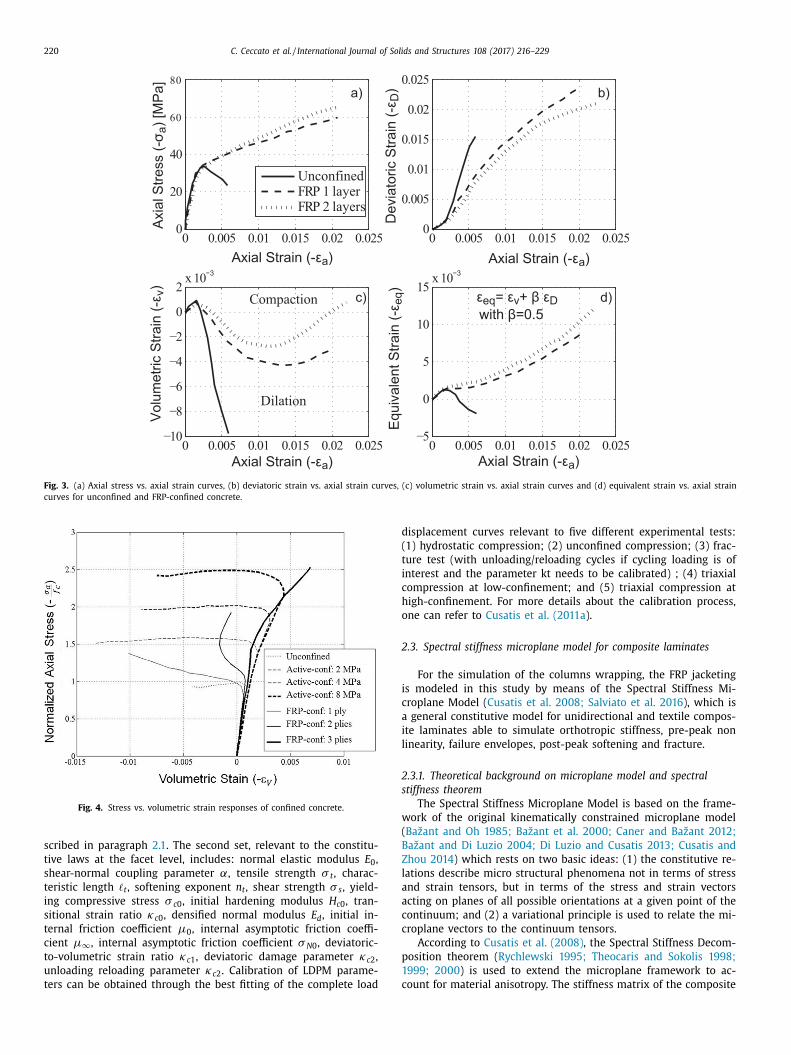
Fig. 3 illustrates the typical behavior of FRP confined concrete
olumns compared to unconfined concrete columns, from experi-
ental data by Wang and Wu (2008) . The deviatoric strain vs. axial
train curves, where strains are computed as defined in Section 2.1 ,
re regularly increasing for both confined and unconfined concrete.
n the contrary, while the volumetric strain vs. axial strain curves
how a different behavior: after an initial compaction, the material
xpands as long as the external confinement is able to contrast it
y constraining the lateral deformations. The stiffer the wrapping,
he sooner the material can reverse the dilation trend and experi-
nce re-compaction. Moreover, if the confining stress is high, the
aterial does not experience dilation at all.
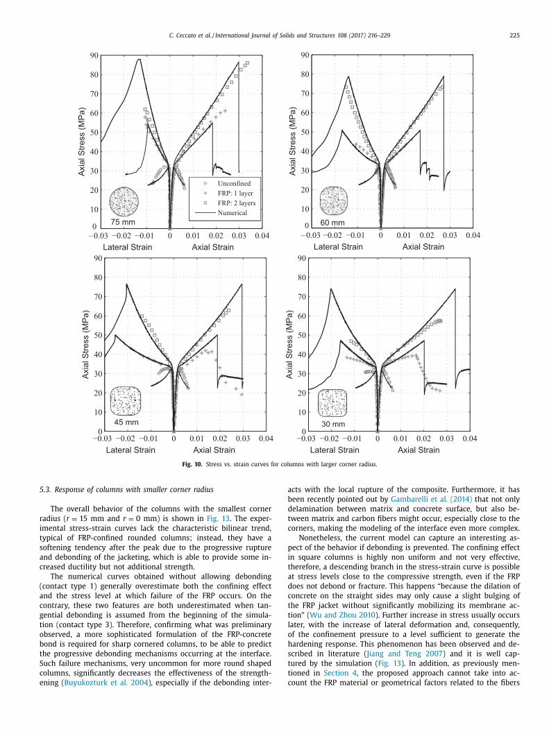
The same behavior is shown in Fig. 4 , where the axial stress is
lotted against the volumetric strain for both actively and passively
onfined concrete specimens. As described in detail in Teng and
am (2004) , for active confinement, the change from compaction
o dilation occurs at different stress levels depending on the con-
ning pressure, and thereafter the dilation tendency remains up
o failure. For passive confinement, instead, dilatation can be taken
ver again by compaction, therefore the accurate description of the
ardening function around the zero volumetric strains is particu-
arly crucial in this case.
To overcome the discussed limitations of the LDPM formula-
ion, a new definition for the hardening modulus is proposed in
his work with Eq. (9) . The hardening modulus H c is formulated
o allow a continuous behavior for compaction to dilation transi-
ions:
c =
H c0 − H c1
1 + κc2 〈 r DV − κc1 〉 + H c1 ; (9a)
DV =
⎧ ⎨
⎩
− | ε D | ε V − ε V 0
for ε V ≤ 0
| ε D | ε V 0
for ε V > 0
(9b)
with ε V 0 = κc3 · ε 0 = 0 . 1 · ε 0 ( κc3 = 0 . 1 ) and H c 1 to be calibrated
ith experimental data.
This new function permits a smooth and coherent transition
rom contraction to expansion and viceversa: the hardening mod-
lus decreases continuously for increasing volumetric strain and
onstant deviatoric strain. Similarly, for constant volumetric strain,
c decreases for increasing (in absolute value) deviatoric strains.
.2.1. Calibration
Two sets of parameters control LDPM response. The first set,
elevant to the geometrical definition of the mesostructure, is de-
220 C. Ceccato et al. / International Journal of Solids and Structures 108 (2017) 216–229
a)
c) d)
b)
Fig. 3. (a) Axial stress vs. axial strain curves, (b) deviatoric strain vs. axial strain curves, (c) volumetric strain vs. axial strain curves and (d) equivalent strain vs. axial strain
curves for unconfined and FRP-confined concrete.
Fig. 4. Stress vs. volumetric strain responses of confined concrete.
d
(
t
i
c
h
o
2
i
c
a
i
l
2
s
w
(
B
Z
l
a
a
c
c
p
1
c
scribed in paragraph 2.1 . The second set, relevant to the constitu-
tive laws at the facet level, includes: normal elastic modulus E 0 ,
shear-normal coupling parameter α, tensile strength σ t , charac-
teristic length � t , softening exponent n t , shear strength σ s , yield-
ing compressive stress σ c 0 , initial hardening modulus H c 0 , tran-
sitional strain ratio κc 0 , densified normal modulus E d , initial in-
ternal friction coefficient μ0 , internal asymptotic friction coeffi-
cient μ∞
, internal asymptotic friction coefficient σ N 0 , deviatoric-
to-volumetric strain ratio κc 1 , deviatoric damage parameter κc 2 ,
unloading reloading parameter κc 2 . Calibration of LDPM parame-
ters can be obtained through the best fitting of the complete load
isplacement curves relevant to five different experimental tests:
1) hydrostatic compression; (2) unconfined compression; (3) frac-
ure test (with unloading/reloading cycles if cycling loading is of
nterest and the parameter kt needs to be calibrated) ; (4) triaxial
ompression at low-confinement; and (5) triaxial compression at
igh-confinement. For more details about the calibration process,
ne can refer to Cusatis et al. (2011a ).
.3. Spectral stiffness microplane model for composite laminates
For the simulation of the columns wrapping, the FRP jacketing
s modeled in this study by means of the Spectral Stiffness Mi-
roplane Model ( Cusatis et al. 2008; Salviato et al. 2016 ), which is
general constitutive model for unidirectional and textile compos-
te laminates able to simulate orthotropic stiffness, pre-peak non
inearity, failure envelopes, post-peak softening and fracture.
.3.1. Theoretical background on microplane model and spectral
tiffness theorem
The Spectral Stiffness Microplane Model is based on the frame-
ork of the original kinematically constrained microplane model
Bažant and Oh 1985; Bažant et al. 20 0 0; Caner and Bažant 2012;
ažant and Di Luzio 2004; Di Luzio and Cusatis 2013; Cusatis and
hou 2014 ) which rests on two basic ideas: (1) the constitutive re-
ations describe micro structural phenomena not in terms of stress
nd strain tensors, but in terms of the stress and strain vectors
cting on planes of all possible orientations at a given point of the
ontinuum; and (2) a variational principle is used to relate the mi-
roplane vectors to the continuum tensors.
According to Cusatis et al. (2008) , the Spectral Stiffness Decom-
osition theorem ( Rychlewski 1995; Theocaris and Sokolis 1998;
999; 20 0 0 ) is used to extend the microplane framework to ac-
ount for material anisotropy. The stiffness matrix of the composite

C. Ceccato et al. / International Journal of Solids and Structures 108 (2017) 216–229 221
Fig. 5. Schematic representation of (a) Representative Unite Cell for FRP; (b) local
spherical coordinate system.
C
C
w
a
f
t
t
i
s
σ
I
t
i
c
e
c
ε
w
P
i
m
a
m
c
b
t
o
d
c
n
m
t
I
h
a
a
f
s
s
s
t
σ
w
p
C
s
r
σ
w
C
2
e √s
t
i
t
δ
B
s
t
σ
t
σ
s
a
r
f
p
f
b
I
c
i
t
m
r
t
o
d
p
p
e
t
is decomposed as follows:
=
∑
I
λ(I) C
(I) (10)
here I = 1 , 2 . . . 6 , λ( I ) are the eigenvalues of the stiffness matrix
nd C
(I) =
∑
n �In �T In
are a set of second-order tensors constructed
rom the elastic eigenvectors �I . The I -th eigenvector �I has mul-
iplicity n and is normalized such that �T I C
(I) �I = λ(I) .
An important characteristic of the elastic eigenmatrices C
( I ) is
hat they provide a way to decompose the stress and strain tensors
nto energetically orthogonal modes. These are called here eigen-
tresses and eigenstrains and are defined as:
I = C
(I) σ and ε I = C
(I) ε (11)
t is easy to show that σ =
∑
I σI and ε =
∑
I ε I whereas the rela-
ion between eigenstresses and eigenstrains can be found introduc-
ng the related elastic eigenvalues: σI = λ(I) ε I . By the spectral de-
omposition of the strain tensor and a separate projection of each
igenstrain, each microplane vector can be decomposed into mi-
roplane eigenstrain vectors as:
P =
N ∑
I
ε
(I) P
where
{ε
(I) P
= P ε
(I) = P
(I) ε
P
(I) = PC
(I) (12)
here N = number of independent eigenmodes and:
=
⎡
⎣
N 11 N 22 N 33
√
2 N 23
√
2 N 13
√
2 N 12
M 11 M 22 M 33
√
2 M 23
√
2 M 13
√
2 M 12
L 11 L 22 L 33
√
2 L 23
√
2 L 13
√
2 L 12
⎤
⎦ (13)
s a 3 × 6 matrix relating the macroscopic strain tensor to the
icroplane strain as a function of the plane orientation, where ε ε ε nd σ are expressed in Kelvin notation, N i j = n i n j , M i j = (m i n j + j n i ) / 2 and L i j = (l i n j + l j n i ) / 2 , where n i , m i and l i define a lo-
al Cartesian reference system on the generic microplane with n i eing the i th component of the normal unit vectors and l i , m i
he i th components of two mutually orthogonal unit vectors also
rthogonal to n i ( Fig. 5 a). With reference to the spherical coor-
inate system represented in Fig. 5 b, the foregoing components
an be expressed as a function of the spherical angles θ and ϕ:
1 = sin θ cos ϕ, n 2 = sin θ sin ϕ, n 3 = cos θ while one can choose
1 = cos θ cos ϕ, m 2 = cos θ sin ϕ, m 3 = − sin θ which gives, for or-
hogonality, l 1 = − sin ϕ, l 2 = cos ϕ and l 3 = 0 ( Cusatis et al. 2008 ).
n this way, different constitutive laws describing the material be-
avior at the microplane level can be related to each eigenmode,
llowing not only the description of the material anisotropy but
lso to address the different damaging mechanisms related to dif-
erent loading conditions. Accordingly, from the microplane eigen-
trains, the microplane eigenstresses σ(I) P
can be defined through
tpecific constitutive laws : σ(I) P
= f ( ε ε ε P1 , ε ε ε P2 . . . ) ε ε ε (I) P
and the macro-
copic stress tensor can be computed through the principle of vir-
ual work ( Cusatis et al. 2008 ):
=
3
2 π
∫ �
P
T N ∑
I
σ(I) P
d � (14)
here � is the surface of a unit hemi-sphere representing all the
ossible microplane orientations.
onstitutive laws: elastic behavior
The elastic behavior is formulated by assuming that normal and
hear eigenstresses on the microplanes are proportional to the cor-
esponding eigenstrains:
(I) N
= λ(I) ε (I) N
, σ (I) M
= λ(I) ε (I) M
, σ (I) L
= λ(I) ε (I) L
(15)
here λ(I) = I th elastic eigenvalue.
onstitutive laws: inelastic behavior
Similarly to previous work by Cusatis ( Cusatis et al. 2003;
011b ), the inelastic constitutive laws for each eigenmode are
xpressed introducing an effective eigenstrain defined as: ε (I) =
(ε (I) N
) 2 + (ε (I) T
) 2 where ε (I) T
=
√
(ε (I) M
) 2 + (ε (I) L
) 2 = t otal shear
train component of I th microplane eigenstrain. The relation be-
ween the stress and strain microplane components can be found
ntroducing an effective eigenstress, σ ( I ) and imposing the consis-
ency of the virtual work:
W I = σ (I) δε (I) =
σ (I)
ε (I) ( ε N δε N + ε M
δε M
+ ε L δε L ) (I) = ( σN δε N )
(I)
+ ( σM
δε M
) (I) + ( σL δε L )
(I) (16)
y means of Eq. (16 ), the relationship between normal and
hear stresses versus normal and shear strains can be formulated
hrough damage-type constitutive equations:
(I) N
=
(σ
ε N ε
)(I)
, σ (I) M
=
(σ
ε M
ε
)(I)
, σ (I) L
=
(σ
ε L ε
)(I)
(17)
The effective stress σ ( I ) is assumed to be incrementally elas-
ic, i.e. ˙ σ (I) = λ(I) ˙ ε (I) and it is formulated such that 0 ≤ σ (I) ≤(I) bi
(ε (1) , ε (2) . . . , θ, ϕ) where σ (I) bi
(ε (1) , ε (2) . . . , θ, ϕ) with sub-
cript i = t for tension and i = c for compression is a limiting bound-
ry enforced through a vertical (at constant strain) return algo-
ithm. It is worth mentioning here that, in general, σ (I) bi
might be a
unction of the microplane orientation and of the equivalent strains
ertaining to other modes. This allows to inherently embed in the
ormulation the effects of damage anisotropy and the interaction
etween damaging mechanisms.
nelastic behavior in the fiber direction
Cusatis et al. (2008) showed that the stiffness tensor for a UD
omposite, treated as transversely isotropic, can be decomposed
nto 4 energetically orthogonal eigenmodes, each being associated
o a particular type of deformation. Mode 1 is related to the nor-
al and shear deformation in out-of-plane direction, mode 2 is
elated to a macroscopic normal deformation in the direction of
he fibers, mode 3 is associated to an in-plane normal deformation
rthogonal to the fibers and mode 4 is related to in-plane shear
eformation. In this work, it is assumed that failure of FRP hap-
ens mainly by fiber fracture and pullout. Accordingly, a strain de-
endent nonlinear constitutive law is defined for mode 2 whereas
lastic behavior is assumed for all the other modes. This assump-
ion is largely supported by the experimental analysis of frac-
ure surfaces of the failed composite jackets. The strain dependent

222 C. Ceccato et al. / International Journal of Solids and Structures 108 (2017) 216–229
Fig. 6. Corner radius variations of the column cross section.
Table 1
Macroscopic material properties.
Property Concrete FRP sheet
Fiber dir. Transverse dir.
Modulus of elasticity (MPa) 30 ,0 0 0 230 ,0 0 0 30 ,0 0 0
Poisson’s ratio 0 .2 - 0 .25
Shear modulus (MPa) - 4 ,0 0 0 a 1 ,300 a
Compressive strength (MPa) 31 - -
Tensile strength (MPa) 3 a 3482 -
Fracture energy (N/mm) 0 .14 a 220 a -
a Estimated value.
Fig. 7. Geometry example of column ( r = 30 mm). (a) Concrete column with load-
ing plates, (b) FRP jacket.
3
m
t
a
o
c
t
r
i
t
p
t
n
t
t
i
f
w
M
σ
μ
m
e
f
s
a
m
a
p
c
t
v
a
c
boundary in tension, ε (2) N
≥ 0 , can be expressed by the following
equations:
σ (2) bt
= s (2) ( θ, ϕ ) exp
[
−( ⟨
ε (2 −t) max − ε (2)
0 t
⟩k (2)
bt
) a t2 ]
(18)
where s (2) ( θ, ϕ ) = s (2) 0
cos 2 (θ ) with s (2) 0
= mode 2 microplane ten-
sile strength. The boundary σ (2) bt
evolves exponentially as a func-
tion of the maximum effective strain, which is a history-dependent
variable defined as ε (2 −t) max (t) = max τ≤t [ ε (2) (t)] . The exponential
decay of the boundary σ (2) bt
starts when the maximum effective
strain reaches its elastic limit ε (2) 0 t
(θ, ϕ) = s (2) /λ(2) . For the sake of
simplicity, the behavior of FRP is assumed linear elastic in com-
pression, since failure always occurs in tension for the cases under
study. The total number of required parameters to describe mode
2 in tension is 3, s (2) 0
, k (2) bt
, a t 2 and they need to be calibrated ac-
cording to experimental data.
3. Numerical analysis of FRP confined concrete
3.1. Material properties and experimental tests
The experimental tests performed by Wang and Wu (2008) are
taken as a reference for the present numerical study, where con-
crete specimens (width/ height = 150 mm/300 mm) with differ-
ent corner radii ( Fig. 6 ), unconfined and wrapped by 1 or 2 car-
bon FRP plies (equivalent thickness per layer s = 0 . 165 mm), are
subjected to compression. The concrete used in the experiments
was based on the following mix design: c = 280 kg/m
3 (cement
contect, estimated), w/c = 0 . 77 (water to cement ratio), a/c = 7 . 5
(aggregate to cement ratio, estimated), d a = 10 mm (max aggre-
gate size), n f = 0 . 5 (Fuller curve exponent, estimated). Macroscopic
elastic and strength properties of the materials are summarized in
Table 1 .
After sanding and cleaning the specimen surface, the FRP was
wrapped around it by typical manual lay-up procedure, orienting
the fibers in the hoop direction and forming one or two layers.
Strain gauges were mounted prior to the testing at multiple points
at the mid-height of the specimens to measure the strains at dif-
ferent locations of the FRP laminate. Three identical specimens for
each condition were tested and the average responses were re-
ported in the publication ( Wang and Wu 2008 ).
.2. Model generation
As described in Section 2.1 , the randomly generated concrete
eso-structure is constructed by defining the coarse aggregate par-
icles on the basis of the concrete mix design and the minimum
ggregate size ( d 0 = 5 mm hereinafter), governing the resolution
f the model.
The LDPM parameters, required for the definition of the facet
onstitutive law ( Cusatis et al. 2011b; 2011a ), are calibrated
hrough the best fitting of the complete load-displacement curves
elevant to different experimental tests. As previously mentioned,
n general hydrostatic compression, unconfined compression, frac-
ure test, triaxial compression at low-confinement, triaxial com-
ression at high-confinement are needed for a complete calibra-
ion. In the present study, all needed experimental curves were
ot available from Wang and Wu (2008) , consequently some of
he parameters were estimated from other available experimen-
al data relevant to the concrete mixes similar to the ones under
nvestigation. The experimental axial stress vs. axial strain curve
or circular specimens unconfined and confined with one FRP layer
ere fitted using the following LDPM parameters: E 0 = 40 , 0 0 0
Pa, α = 0 . 25 , σt = 3 . 65 MPa, l t = 200 mm, σs /σt = 2 . 5 , n t = 0 . 2 ,
c0 = 45 MPa, H c0 /E 0 = 0 . 3 , κc0 = 4 , κc1 = 1 , κc2 = 5 , H c1 /E 0 = 0 . 1 ,
0 = 0 . 2 , μ∞
= 0 , σN0 = 600 MPa, E d /E 0 = 1 .
In the simulations, the load was applied through steel platens,
odeled as rigid bodies, directly in contact with the specimens
nds and equipped with a constraint algorithm to simulate high
riction conditions. Specifically, the adopted constraint restricts the
et of top and bottom nodes of the specimen to move on the top
nd bottom platen surface, respectively, with a master-slave for-
ulation for the direction perpendicular to the surface and with
stick-slip friction model for the resistance to sliding along the
lane. The friction coefficient μ is computed as a function of the
ontact slippage v , μ(v ) = μd + (μs − μd ) v 0 / (v 0 + v ) with the fric-
ion parameters optimized for high friction ( μs = 0 . 13 , μd = 0 . 015 ,
0 = 1 . 3 mm) according to Cusatis et al. 2011a . Fig. 7 shows an ex-
mple of LDPM discretization and the rigid plates for the boundary
onditions.

C. Ceccato et al. / International Journal of Solids and Structures 108 (2017) 216–229 223
Fig. 8. Stress-strain curve in the FRP (fibers direction).
e
s
t
m
d
s
G
2
p
c
c
o
S
m
×
M
p
t
g
4
t
s
r
t
i
m
L
b
c
t
c
s
2
p
s
i
a
w
d
T
o
f
s
e
F
t
g
d
n
a
a
m
t
F
F
s
s
t
b
a
r
m
o
5
5
F
t
p
u
fi
F
o
f
t
o
u
c
t
t
o
F
o
f
f
i
c
s
s
i
p
a
c
c
c
i
The FRP jackets are modeled by means of quadrilateral shell el-
ments with one in-plane integration point and physical hourglass
tabilization ( Belytschko and Leviathan 1994 ) and they are given
he orthotropic behavior through the described spectral stiffness
icroplane model, which allows orienting the fibers in the hoop
irection. The mechanical properties of the FRP laminates are as-
igned according to the manufacturer data ( Wang and Wu 2008;
ambarelli et al. 2014 ) or estimated from literature ( Mottram
004; Gerstle 1991 ) and the corresponding parameters are re-
orted in Table 1 . The parameters of the spectral stiffness mi-
roplane model governing the inelastic behavior of the fibers were
alibrated according to given ultimate stress and estimated value
f fracture energy, according to Salviato et al. (2016) (see Table 1 ).
purious mesh sensitivity due to strain localization was avoided by
eans of the crack band model ( Bažant and Oh 1985 ). For a 5 mm
5 mm shell element the calibrated parameters are: s (2) 0
= 3 , 482
Pa, k (2) bt
= 0 . 04 , a t2 = 0 . 75 . The resulting response of the com-
osite in the fiber direction is shown in Fig. 8 . Considerations on
he interface behavior between concrete column and FRP plies are
iven in Section 5.1 .
. Considerations on the FRP ultimate condition
Failure of FRP-confined column is always due to the rupture of
he FRP jacket, governed by the fracturing tensile strain or tensile
trength in the hoop direction ( Teng and Lam 2004 ). The mate-
ial allows limited stress redistribution because of its elastic brit-
le character so the identification of the fracturing tensile strain
s paramount to understand the column collapse mechanisms. In
any existing theoretical or numerical models ( Teng et al. 2001;
am and Teng 2004a ) the tensile rupture of FRP is characterized
y the hoop strain reaching its fracturing limit as measured from
oupon tests. However, different experimental results have shown
hat the hoop rupture strains of FRP measured in FRP-confined
olumns are on average significantly lower than coupon failure
trains (see Smith et al. 2010; Xiao and Wu 20 0 0; Pessiki et al.
0 01; Shahawy et al. 20 0 0 ). In particular, Wang and Wu (20 08) re-
ort a FRP fracturing strain at least 25% lower than the one mea-
ured on coupons and that the reduction is more significant (a)
n the corners and (b) in case of multiple layers. A systematic
nalysis of the factors influencing the fracturing condition of FRP-
rapped concrete columns is given by Chen et al. (2013) , where
ifferent causes were highlighted to affect the composite rupture.
hey are herein briefly listed: (1) geometrical factors, such as ge-
metrical discontinuities, FRP overlap region, geometrical imper-
ections and curvature of the FRP jacket; (2) FRP material factors,
uch as unintentional fiber misorientation, misalignment and un-
ven tension of fibers, damage of fibers, triaxial stress state in the
RP; (3) concrete material factors, such as nonuniform deforma-
ion and strain localization in concrete; (4) adhesive material and
eometry factors, such as mechanical properties and geometrical
etails of the adhesive; (5) loading factors, such as eccentric or
on uniform loading, stressing attributable to thermal deformation
nd creep.
The numerical model developed in the present paper is able to
ccount for the concrete material factors, being LDPM a meso-scale
odel. LDPM captures naturally the non uniform local deforma-
ions on concrete, leading to non uniform strain deformation in the
RP, in both the circumferential and axial direction. Consequently,
RP strain localization resulting from concrete cracking can be also
imulated. However, the FRP jacket is modeled with orthotropic
hell elements of equivalent thickness s = 0 . 165 mm/layer and the
ensile properties of a wet layup processed FRP are assigned on the
asis of the nominal thickness of the fiber/fabric sheet, because the
ctual thickness is difficult to control and the resin contribution is
elatively small ( Lam and Teng 2004b ). For these reasons, the nu-
erical simulations in this study cannot include any FRP material
r geometrical factors related to fibers or matrix.
. Results and discussion
.1. Preliminary study on the FRP-concrete interface
In a preliminary study, different types of formulations for the
RP-concrete interaction were examined, by using the square and
he circular shaped columns wrapped by 1 layer of composite. In
articular, the following options were explored in order to eval-
ate the sensitivity of the model to the interface behavior. The
rst option (1) consists of a master-slave formulation where the
RP nodes (slaves) are forced to lay on the external lateral surface
f the concrete column (master) and both normal and tangential
orces are transferred. This means that not slippage is allowed at
he interface, corresponding to cases in which debonding does not
ccur. In the second option (2), a master-slave formulation is still
sed but the nodes of the external lateral surface of the concrete
olumn (slaves) are forced to lay on the internal lateral surface of
he FRP jacket (master) and both normal and tangential forces are
ransferred. Again, no slippage at the interface is allowed. The third
ption (3) is characterized by master-slave formulation where the
RP nodes (slaves) are forced to lay on the external lateral surface
f the concrete column (master) and only normal forces are trans-
erred. This means that relative slippage at the interface can occur
reely, representing a fully debonded situation. The final option (4)
s similar to (3) but the nodes of the external lateral surface of the
oncrete column (slaves) are forced to lay on the internal lateral
urface of the FRP jacket (master).
Rotations of FRP shell elements and LDPM particles are not con-
trained in any of the 4 cases.
The comparison in terms of axial stress vs. axial strain curves
s shown in Fig. 9 . Results in Fig. 9 a shows that it is more appro-
riate to consider the lateral surface of concrete column as master
nd the FRP as slave, in the contact definition. As a matter of fact,
urves (2) and (4) do not describe properly the behavior of the cir-
ular column because the confining effect provided by the jacket is
onsiderably underestimated. The response is much more realistic
n case of curves (1) and (3), as it emerges from the comparison

224 C. Ceccato et al. / International Journal of Solids and Structures 108 (2017) 216–229
Fig. 9. Comparison between experimental and numerical stress vs. strain curves for (a) the square column ( r = 0 mm) and (b) the circular column ( r = 75 mm) with 1 FRP
ply. (1), (2), (3), (4) correspond to various type of FRP-concrete contact algorithm, as described in the text.
i
c
p
c
i
a
F
c
t
h
e
l
r
p
r
a
f
o
f
W
F
a
B
d
w
o
f
p
d
q
o
w
t
b
p
f
with the experimental data, and it does not change significantly
whether the tangential component is taken into account or not.
This results indicate that the circular columns are less sensitive to
debonding due to the symmetric character of the deformation pro-
cess, at least prior to failure. In Fig. 9 b, the comparison between
curve (1) and (3) shows that, for square columns, the confinement
effect decreases substantially when the tangential interaction be-
tween the surfaces is neglected. This proves that the debonding
mechanisms play a major role due to the discontinuities associated
with sharp corners.
According to these observations, one can conclude that the de-
velopment of a proper contact algorithm for the bond, able to cap-
ture the progressive debonding effects, is indeed important, espe-
cially for the right-cornered sections. In the examples discussed
in the following sections, the interaction between the concrete
columns and the FRP plies is modeled with the type (1) algorithm
in case of larger corner radius. For the columns with smaller corner
radius, the predictions with algorithm (1) and (3), are compared
and discussed.
5.2. Response of columns with larger corner radius
The uniaxial stress-strain curves in Fig. 10 are relevant to spec-
imens with corner radius from r = 30 mm to r = 75 mm. Ex-
perimental and the numerical responses of unconfined and FRP-
confined concrete columns (with 1 layer and 2 layers) are com-
pared for each cross section. Similarly to the experiments, the ax-
ial stress is obtained by dividing the global axial displacement over
the specimen height and the lateral strain as an average of the ra-
dial displacements over the undeformed radial length, measured
at the middle of each side face and at half-height of the speci-
men. The results show that, after the calibration of the parameters
through the unconfined concrete loading curves and the response
of the circular columns, the model can capture the behavior of
concrete columns in compression subjected to uniform and non-
uniform confinement at different levels. As well-known from the
majority of existing experimental tests, the axial stress-axial strain
curves of FRP-confined concrete are characterized by a monoton-
cally hardening bilinear shape, where the change in shape oc-
urs always at a stress level close to the unconfined concrete com-
ressive strength, as opposed to feature a softening branch typi-
al of actively confined concrete at low confinement. As the ax-
al stress increases, the confining pressure provided by the jacket
lso increases instead of remaining constant and if the stiffness of
RP exceeds a certain threshold value, this confining pressure in-
reases fast enough to ensure that the stress-strain curve is mono-
onically hardening. Naturally, the higher is the FRP stiffness, the
igher is the slope of the second branch, as shown by the typical
volution of stress vs. strain captured for different number of FRP
ayers. This feature of the response is well captured by the cur-
ent model. The corner radius effect is also captured and higher
ost peak stiffness is observed for columns with a larger corner
adius, in both experiments and simulations. Fig. 11 shows stress
nd strain distributions in the FRP jacket at the ultimate condition
or the different columns. All the columns fail by tensile rupture
f the FRP wrap in the midheight region and rupture originates
rom the vicinity of the corners, as seen in the experiments (e.g.
ang et al. 2012; Dalgic et al. 2016; Wang and Wu 2008 ). In
ig. 12 , the fracture patterns developed in the concrete columns
re reported through the plotting of the meso-scale crack opening.
efore the FRP rupture, the damage in concrete is symmetrically
istributed according to the geometry and it gradually increases
ith the reduction of the corner radius, especially along the sides
f the specimens according to the reduction of the confinement ef-
ects. With the FRP rupture, the symmetry of the response is com-
letely lost: strain and damage localization occur with the sud-
en growing of an inclined fracture in the FRP jacket and conse-
uently a shear band in the concrete element, causing the collapse
f the specimen. The ultimate stress and strain values, together
ith the failure modes, are captured with very good approxima-
ion by the proposed model (see Fig. 10 ), proving that the com-
ination of LDPM and SMPM can provide a numerical tool more
owerful and realistic than the majority of the existing FE models
or FRP-confined concrete.
C. Ceccato et al. / International Journal of Solids and Structures 108 (2017) 216–229 225
Fig. 10. Stress vs. strain curves for columns with larger corner radius.
5
r
i
t
s
a
c
(
a
c
g
t
o
b
t
S
c
e
a
b
d
t
c
p
i
t
a
d
c
t
t
l
o
h
s
t
t
c
.3. Response of columns with smaller corner radius
The overall behavior of the columns with the smallest corner
adius ( r = 15 mm and r = 0 mm) is shown in Fig. 13 . The exper-
mental stress-strain curves lack the characteristic bilinear trend,
ypical of FRP-confined rounded columns; instead, they have a
oftening tendency after the peak due to the progressive rupture
nd debonding of the jacketing, which is able to provide some in-
reased ductility but not additional strength.
The numerical curves obtained without allowing debonding
contact type 1) generally overestimate both the confining effect
nd the stress level at which failure of the FRP occurs. On the
ontrary, these two features are both underestimated when tan-
ential debonding is assumed from the beginning of the simula-
ion (contact type 3). Therefore, confirming what was preliminary
bserved, a more sophisticated formulation of the FRP-concrete
ond is required for sharp cornered columns, to be able to predict
he progressive debonding mechanisms occurring at the interface.
uch failure mechanisms, very uncommon for more round shaped
olumns, significantly decreases the effectiveness of the strength-
ning ( Buyukozturk et al. 2004 ), especially if the debonding inter-
cts with the local rupture of the composite. Furthermore, it has
een recently pointed out by Gambarelli et al. (2014) that not only
elamination between matrix and concrete surface, but also be-
ween matrix and carbon fibers might occur, especially close to the
orners, making the modeling of the interface even more complex.
Nonetheless, the current model can capture an interesting as-
ect of the behavior if debonding is prevented. The confining effect
n square columns is highly non uniform and not very effective,
herefore, a descending branch in the stress-strain curve is possible
t stress levels close to the compressive strength, even if the FRP
oes not debond or fracture. This happens “because the dilation of
oncrete on the straight sides may only cause a slight bulging of
he FRP jacket without significantly mobilizing its membrane ac-
ion” ( Wu and Zhou 2010 ). Further increase in stress usually occurs
ater, with the increase of lateral deformation and, consequently,
f the confinement pressure to a level sufficient to generate the
ardening response. This phenomenon has been observed and de-
cribed in literature ( Jiang and Teng 2007 ) and it is well cap-
ured by the simulation ( Fig. 13 ). In addition, as previously men-
ioned in Section 4 , the proposed approach cannot take into ac-
ount the FRP material or geometrical factors related to the fibers
226 C. Ceccato et al. / International Journal of Solids and Structures 108 (2017) 216–229
Fig. 11. Hoop stress and strain distribution in the FRP at the ultimate condition for
(a) r = 30 mm, (b) r = 45 mm, (c) r = 60 mm, (d) r = 75 mm.
Fig. 12. Crack Opening in the concrete columns for (a) r = 30 mm, (b) r = 45 mm,
(c) r = 60 mm, (d) r = 75 mm.
m
a
t
o
r
c
w
t
s
m
c
w
m
c
t
or adhesive that lead to the rupture of the composite and, conse-
quently, to the column collapse. These factors tend to have a more
important effect in the case of sharp corner columns. The jacket
is modeled with orthotropic shell elements of nominal thickness
s = 0 . 165 mm/layer, being the actual thickness difficult to control
and the contribution of the matrix relatively small ( Lam and Teng
2004b ). However, neglecting the matrix contribution when a sub-
stantial difference between the nominal and the actual thickness
occurs can lead to inaccurate approximations in the composite re-
sponse. For instance, the flexural behavior, and the consequent
triaxial stress state, cannot be modeled accurately in the case of
sharp-angled cross sections, where the FRP soon experiences high
local stress concentrations and local damage accumulation.
6. Conclusions and further research
A three-dimensional framework for the numerical simulation of
concrete columns confined by FRP loaded in compression has been
presented in this paper. The approach is based on a meso-scale
odel for concrete, the Lattice Discrete Particle Model (LDPM) and
microstructural inspired constitutive equation for FRP, the Spec-
ral Microplane Model (SMPM). With the described improvement
f the constitutive law in compression for LDPM and after the pa-
ameters calibration, the model can predict the behavior of FRP
onfined concrete and its sensitivity to the stiffness of the FRP
rapping and to the shape of the cross section. With reference
o the experimental data used for this study, the response of the
pecimens with largest corner radius (from r = 30 mm to r = 75
m) is accurately described, not only in terms of stress vs. strain
urves but also in terms of ultimate condition, which is captured
ith a very good accuracy for the different cross sections. The
odel can realistically capture the fracture patterns developing in
oncrete during the loading history and the failure modes related
o the FRP jacket fracture. The specimens with sharpest corner ra-

C. Ceccato et al. / International Journal of Solids and Structures 108 (2017) 216–229 227
Fig. 13. Stress vs. strain curves for columns with smaller corner radius.
d
m
t
e
p
i
o
t
i
e
m
c
f
t
F
m
t
t
t
A
N
a
t
w
d
R
A
B
B
B
B
B
B
B
C
C
C
C
C
C
C
C
D
D
D
D
E
F
ius ( r = 0 mm and r = 15 mm), instead, require a more advanced
odeling of the FRP jacket and, in particular, of the contact be-
ween FRP and concrete in order to capture the complex phenom-
na related to the local stress concentrations and FRP debonding
rocesses. In fact, it has been observed that not allowing debond-
ng between FRP and concrete generally lead to an overestimation
f the confining effect and the stress level at FRP failure, while
hese two features are both underestimated if tangential debond-
ng is assumed since the beginning of the simulation. This differ-
nce is neither observed in the experiment nor predicted by the
odel for large radius columns.
Contrarily to most models in the literature that tackle only spe-
ific aspects of FRP reinforcing, the model presented in this ef-
ort has potential to provide a complete and general computa-
ional framework. The key factors for a successful simulation of
RP-concrete systems are related to the modeling of (a) concrete
aterial, (b) FRP material, (c) FRP-concrete interface. The results in
his paper show that the formulated model successfully addresses
he first two aspects, while the last requires further improvements
hat will be pursued in the near future.
cknowledgments
The work of the last author was partially supported by the
ational Science Foundation under grant no. CMMI-1435923 . The
uthors would like to thank ES3, Engineering and Software Sys-
em Solutions, Inc. for the computational support with the soft-
are MARS and Prof. J. G. Teng and Prof. C. Carloni for stimulating
iscussions.
eferences
lnaggar, M., Cusatis, G., Di Luzio, G., 2013. Lattice discrete particle modeling(LDPM) of alkali silica reaction (ASR) deterioration of concrete structures. Cem.
Concr. Compos. 41, 45–59 . http:/dx.doi.org/10.1016/j.cemconcomp.2013.04.015 ažant, Z.P., Caner, F.C., Carol, I., Adley, M.D., Akers, S.A., 20 0 0. Microplane model M4
for concrete. i: formulation with work-conjugate deviatoric stress. J. Eng. Mech.126 (9), 944–953. doi: 10.1061/(ASCE)0733-9399(20 0 0)126:9(944) .
ažant, Z.P., Di Luzio, G., 2004. Nonlocal microplane model with strain-softening
yield limits. Int. J. Solids Struct. 41 (24–25), 7209–7240. doi: 10.1016/j.ijsolstr.2004.05.065 .
ažant, Z.P., Oh, B.H., 1985. Microplane model for progressive fracture of con-crete and rock. J. Eng. Mech. 111 (4), 559–582. http://dx.doi.org/10.1061/(ASCE)
0733-9399(1985)111:4(559) .
ažant, Z.P., Prat, P.C., 1988. Microplane model for brittle plastic material: itheory. J. Eng. Mech. 114 (10), 1672–1688. http://dx.doi.org/10.1061/(ASCE)
0733-9399(1988)114:10(1672) . elytschko, T., Leviathan, I., 1994. Physical stabilization of the 4-node shell element
with one point quadrature. Comput. Methods Appl. Mech. Eng. 113 (3–4), 321–350. http://dx.doi.org/10.1016/0 045-7825(94)90 052-3 .
inici, B., 2005. An analytical model for stress-strain behavior of confined concrete.
Eng. Struct. 27 (7), 1040–1051. http://dx.doi.org/10.1016/j.engstruct.20 05.03.0 02 .uyukozturk, O., Gunes, O., Karaca, E., 2004. Progress on understanding debond-
ing problems in reinforced concrete and steel members strengthened usingFRP composites. Constr. Build. Mater. (18) 9–19. doi: 10.1016/S0950-0618(03)
0 0 094-1 . aner, F.C., Bažant, Z.P., 2012. Microplane model M7 for plain concrete. i: formu-
lation. J. Eng. Mech. 139 (12), 1714–1723. http://dx.doi.org/10.1061/(ASCE)EM.
1943-7889.0 0 0 0570 . arol, I., Bažant, Z.P., 1997. Damage and plasticity in microplane theory. Int. J. Solids
Struct. 34 (29), 3807–3835. http://dx.doi.org/10.1016/S0 020-7683(96)0 0238-7 . hen, J., Li, S., Bisby, L., 2013. Factors affecting the ultimate condition of FRP-
wrapped concrete columns. J. Compos. Constr. 17 (1), 67–78. doi: 10.1061/(ASCE)CC.1943-5614.0 0 0 0314 .
usatis, G. , Bažant, Z. , Cedolin, L. , 2003. Confinement-shear lattice model for con-
crete damage in tension and compression: i. theory. J. Eng. Mech. 129 (12),881–889 .
usatis, G., Beghini, A., Bažant, Z., 2008. Spectral stiffness microplane model forquasibrittle composite laminates-part i: theory. J. Appl. Mech. 75 (2), 021009.
http://dx.doi.org/10.1115/1.2744036 . usatis, G., Mencarelli, A., Pelessone, D., Baylot, J.T., 2011a. Lattice discrete parti-
cle model (LDPM) for failure behavior of concrete. II: calibration and validation.
Cem. Concr. Compos. 33 (9), 891–905. http://dx.doi.org/10.1016/j.cemconcomp.2011.02.010 .
usatis, G., Pelessone, D., Mencarelli, A., 2011b. Lattice discrete particle model(LDPM) for failure behavior of concrete. i: theory. Cem. Concr. Compos. 33 (9),
881–890. http://dx.doi.org/10.1016/j.cemconcomp.2011.02.011 . usatis, G., Zhou, X., 2014. High-order microplane theory for quasi-brittle materials
with multiple characteristic lengths. J. Eng. Mech. 140 (7), 04014046. doi: 10.1061/(ASCE)EM.1943-7889.0 0 0 0747 .
algic, K., Ispir, M., Ilki, A., 2016. Cyclic and monotonic compression behavior of
CFRP-jacketed damaged noncircular concrete prisms. J. Compos. Constr. 20 (1),04015040. doi: 10.1061/(ASCE)CC.1943-5614.0 0 0 0603 .
esprez, C., Mazars, J., Kotronis, P., Paultre, P., 2013. Damage model for FRP-confinedconcrete columns under cyclic loading. Eng. Struct. 48, 519–531. http://dx.doi.
org/10.1016/j.engstruct.2012.09.019 . i Luzio, G., 2007. A symmetric over-nonlocal microplane model M4 for fracture
in concrete. Int. J. Solids Struct. 44 (13), 4418–4441. http://dx.doi.org/10.1016/j.
ijsolstr.2006.11.030 . i Luzio, G., Cusatis, G., 2013. Solidification - microprestress - microplane (SMM)
theory for concrete at early age: theory, validation and application. Int. J. SolidsStruct. 50 (6), 957–975. http://dx.doi.org/10.1016/j.ijsolstr.2012.11.022 .
lsanadedy, H.M., Al-Salloum, Y.A., Alsayed, S.H., Iqbal, R.A., 2012. Experimental andnumerical investigation of size effects in FRP-wrapped concrete columns. Constr.
Build. Mater. 29, 56–72. http://dx.doi.org/10.1016/j.conbuildmat.2011.10.025 .
am, A. , Rizkalla, S. , 2001. Confinement model for axially loaded concrete confinedby circular fiber-reinforced polymer tubes. ACI Struct. J. 98 (4), 451–461 .
228 C. Ceccato et al. / International Journal of Solids and Structures 108 (2017) 216–229
R
S
S
S
S
S
T
T
T
T
T
T
T
W
W
W
W
X
Y
Y
Gambarelli, S., Nisticò, N., Ožbolt, J., 2014. Numerical analysis of compressed con-crete columns confined with CFRP: microplane-based approach. Composites
Part B 67, 303–312. http://dx.doi.org/10.1016/j.compositesb.2014.06.026 . Gerstle, F.P. , 1991. ”Composites”, Encyclopedia of polymer science and engineering.
J. Wiley & sons, New York . Harajli, M.H., 2006. Axial stress-strain relationship for FRP confined circular and
rectangular concrete columns. Cem. Concr. Compos. 28 (10), 938–948. http://dx.doi.org/10.1016/j.cemconcomp.20 06.07.0 05 . Durability and Ductility of FRP
Strengthened Beams, Slabs and Columns
Jiang, J.-F., Wu, Y.-F., 2012. Identification of material parameters for drucker-pragerplasticity model for FRP confined circular concrete columns. Int. J. Solids Struct.
49 (3–4), 445–456. http://dx.doi.org/10.1016/j.ijsolstr.2011.10.002 . Jiang, T., Teng, J., 2007. Analysis-oriented stress-strain models for FRP-confined con-
crete. Eng. Struct. 29 (11), 2968–2986. http://dx.doi.org/10.1016/j.engstruct.2007.01.010 .
Karabinis, A., Rousakis, T., 2002. Concrete confined by FRP material: a plasticity ap-
proach. Eng. Struct. 24 (7), 923–932. doi: 10.1016/S0141-0296(02)0 0 011-1 . Karabinis, A.I. , Rousakis, T.C. , Manolitsi, G.E. , 2008. 3D finite-element analysis of
substandard RC columns strengthened by fiber-reinforced polymer sheets. J.Compos. Constr. 12 (5), 531–540 .
Koksal, H., Doran, B., Turgay, T., 2009. A practical approach for modeling FRPwrapped concrete columns. Constr. Build. Mater. 23 (3), 1429–1437. http://dx.
doi.org/10.1016/j.conbuildmat.20 08.07.0 08 .
Lam, L., Teng, J., 2003. Design-oriented stress-strain model for FRP-confinedconcrete. Constr. Build. Mater. 17 (6–7), 471–489. http://dx.doi.org/10.1016/
S0950-0618(03)0 0 045-X . Fibre Rinforced Polymer composites in construction Lam, L., Teng, J., 2004a. Ultimate condition of fiber reinforced polymer-confined
concrete. J. Compos. Constr. 8 (6), 539–548. doi: 10.1061/(ASCE)1090-0268(2004)8:6(539) .
Lam, L., Teng, J., 2004b. Ultimate condition of fiber reinforced polymer-confined
concrete. J. Compos. Constr. 8 (6), 539–548. doi: 10.1061/(ASCE)1090-0268(2004)8:6(539) .
Maalej, M., Tanwongsval, S., Paramasivam, P., 2003. Modelling of rectangular RCcolumns strengthened with FRP. Cem. Concr. Compos. 25 (2), 263–276. http:
//dx.doi.org/10.1016/S0958-9465(02)0 0 017-3 . Mirmiran, A., Zagers, K., Yuan, W., 20 0 0. Nonlinear finite element modeling of
concrete confined by fiber composites. Finite Elem. Anal. Des. 35 (1), 79–96.
doi: 10.1016/S0168-874X(99)0 0 056-6 . Moran, D.A., Pantelides, C.P., 2012. Elliptical and circular FRP -confined concrete sec-
tions: a mohr-coulomb analytical model. Int. J. Solids Struct. 49 (6), 881–898.http://dx.doi.org/10.1016/j.ijsolstr.2011.12.012 .
Mottram, J. , 2004. Shear modulus of standard pultruded fiber reinforced plastic ma-terial. J. Compos. Constr. 8 (2), 141–147 .
Ozbakkaloglu, T., Lim, J.C., 2013. Axial compressive behavior of FRP-confined con-
crete: experimental test database and a new design-oriented model. CompositesPart B 55, 607–634. http://dx.doi.org/10.1016/j.compositesb.2013.07.025 .
Pelessone, D. , 2015. MARS, Modeling and analysis of the response of structures.User’s manual. ES3 Inc .
Pellegrino, C., Modena, C., 2010. Analytical model for FRP confinement of concretecolumns with and without internal steel reinforcement. J. Compos. Constr. 14
(6), 693–705. http://dx.doi.org/10.1061/(ASCE)CC.1943-5614.0 0 0 0127 . Pessiki, S., Harries, K.A., Kestner, J.T., Sause, R., Ricles, J.M., 2001. Axial behavior of
reinforced concrete columns confined with FRP jackets. J. Compos. Constr. 5 (4),
237–245. doi: 10.1061/(ASCE)1090-0268(2001)5:4(237) . Rousakis, T., Karabinis, A., Kiousis, P., 2007. FRP-Confined concrete members: axial
compression experiments and plasticity modelling. Eng. Struct. 29 (7), 1343–1353. doi: 10.1016/j.engstruct.20 06.08.0 06 .
Rousakis, T.C., Karabinis, A.I., Kiousis, P.D., Tepfers, R., 2008. Analytical modelling ofplastic behaviour of uniformly FRP confined concrete members. Composites Part
B 39 (7–8), 1104–1113. http://dx.doi.org/10.1016/j.compositesb.20 08.05.0 01 .
Rousakis, T.C., Rakitzis, T.D., Karabinis, A.I., 2012. Design-oriented strength modelfor FRP-confined concrete members. J. Compos. Constr. 16 (6), 615–625. http:
//dx.doi.org/10.1061/(ASCE)CC.1943-5614.0 0 0 0295 .
ychlewski, J. , 1995. Unconventional approach to linear elasticity. Arch. Mech. 47,149–171 .
alviato, M., Ashari, S.E., Cusatis, G., 2016. Spectral stiffness microplane model fordamage and fracture of textile composites. Compos. Struct. 137, 170–184. http:
//dx.doi.org/10.1016/j.compstruct.2015.10.033 . chauffert, E.A., Cusatis, G., 2011. Lattice discrete particle model for fiber-reinforced
concrete. i: theory. J. Eng. Mech. 138 (7), 826–833. http://dx.doi.org/10.1061/(ASCE)EM.1943-7889.0 0 0 0387 .
chauffert, E.A., Cusatis, G., Pelessone, D., O’Daniel, J.L., Baylot, J.T., 2012. Lattice dis-
crete particle model for fiber-reinforced concrete. II: tensile fracture and multi-axial loading behavior. J. Eng. Mech. 138 (7), 834–841. http://dx.doi.org/10.1061/
(ASCE)EM.1943-7889.0 0 0 0392 . hahawy, M., Mirmiran, A., Beitelman, T., 20 0 0. Tests and modeling of carbon-
wrapped concrete columns. Composites Part B 31 (6–7), 471–480. http://dx.doi.org/10.1016/S1359-8368(0 0)0 0 021-4 .
Smith, J., Jin, C., Pelessone, D., Cusatis, G., 2015. Dynamics simulations of concrete
and concrete structures through the lattice discrete particle model, pp. 63–74.doi: 10.1061/9780784479117.006 .
mith, S.T., Kim, S.J., Zhang, 2010. Behavior and effectiveness of FRP wrap in theconfinement of large concrete cylinders. J. Compos. Constr. 14 (5), 573–582.
doi: 10.1061/(ASCE)CC.1943-5614.0 0 0 0119 . eng, J., Huang, Y., Lam, L., Ye, L., 2007. Theoretical model for fiber-reinforced
polymer-confined concrete. J. Compos. Constr. 11 (2), 201–210. doi: 10.1061/
(ASCE)1090-0268(2007)11:2(201) . eng, J., Lam, L., 2004. Behavior and modeling of fiber reinforced polymer-confined
concrete. J. Struct. Eng. 130 (11), 1713–1723. http://dx.doi.org/10.1061/(ASCE)0733-9445(2004)130:11(1713) .
eng, J., Lam, L., Lin, G., Lu, J., Xiao, Q., 2015a. Numerical simulation of FRP-jacketed RC columns subjected to cyclic and seismic loading. J. Compos. Constr.
04015021. http://dx.doi.org/10.1061/(ASCE)CC.1943-5614.0 0 0 0584 .
eng, J., Xiao, Q., Yu, T., Lam, L., 2015b. Three-dimensional finite element analysis ofreinforced concrete columns with FRP and/or steel confinement. Eng. Struct. 97,
15–28. http://dx.doi.org/10.1016/j.engstruct.2015.03.030 . Teng, J.G. , Chen, J.F. , Smith, S.T. , Lam, L. , 2001. FRP: Strengthened RC structures. Ad-
dison-Wesley . heocaris, P.S. , Sokolis, D.P. , 1998. Spectral decomposition of the compliance tensor
for anisotropic plates. J. Elast. 51 (2), 89–103 .
heocaris, P.S., Sokolis, D.P., 1999. Spectral decomposition of the linear elastic tensorfor monoclinic symmetry. Acta Crystallogr. Sect. A 55 (4), 635–647. doi: 10.1107/
S0108767398016766 . heocaris, P.S., Sokolis, D.P., 20 0 0. Spectral decomposition of the compliance fourth-
rank tensor for orthotropic materials. Arch. Appl. Mech. 70 (4), 289–306. http://dx.doi.org/10.10 07/s0 0419990 0 066 .
ang, L.-M., Wu, Y.-F., 2008. Effect of corner radius on the performance of CFRP-
confined square concrete columns: test. Eng. Struct. 30 (2), 493–505. http://dx.doi.org/10.1016/j.engstruct.2007.04.016 .
ang, Z., Wang, D., Smith, S.T., Lu, D., 2012. CFRP-Confined square RC columns.i: experimental investigation. J. Compos. Constr. 16 (2), 150–160. doi: 10.1061/
(ASCE)CC.1943-5614.0 0 0 0245 . u, Y., Zhou, Y., 2010. Unified strength model based on Hoek-Brown failure criterion
for circular and square concrete columns confined by FRP. J. Compos. Constr. 14(2), 175–184. doi: 10.1061/(ASCE)CC.1943-5614.0 0 0 0 062 .
u, Y.-F. , 2015. Development of constitutive models for FRP confined concrete
structures, 1, p. 90 . iao, Y., Wu, H., 20 0 0. Compressive behavior of concrete confined by carbon
fiber composite jackets. J. Mater. Civ. Eng. 12 (2), 139–146. doi: 10.1061/(ASCE)0899-1561(20 0 0)12:2(139) .
u, T., Teng, J., Wong, Y., Dong, S., 2010a. Finite element modeling of confinedconcrete i: drucker-prager type plasticity model. Eng. Struct. 32 (3), 665–679.
doi: 10.1016/j.engstruct.2009.11.014 .
u, T., Teng, J., Wong, Y., Dong, S., 2010b. Finite element modeling of confinedconcrete II: plastic-damage model. Eng. Struct. 32 (3), 680–691. doi: 10.1016/j.
engstruct.2009.11.013 .

C. Ceccato et al. / International Journal of Solids and Structures 108 (2017) 216–229 229
(Master) degrees in civil engineering at University of Padova, Italy, where she is now a
University (Evaston, IL, USA), studying meso-scale models for quasi-brittle materials. Her applied to concrete and FRP materials.
gineering from University of Padova (Italy) in 2013. His doctoral research focused on the
experimental characterization of the mechanical behavior of polymer nanocomposites. tant professor, Dr. Salviato worked at the Department of Civil and Environmental Engi-
Fellow, and later as Research Assistant Professor. Currently, he leads the Laboratory for lliam E. Boeing Department of Aeronautics and Astronautics. His research focuses on the
l and functional properties and the formulation of computational models to assist the
d Design and Head of the Department of Civil, Environmental and Architectural Engineer-
ademic Senate, University of Padova, Italy.PhD in Mechanics of Structures. Coordinator of al Committee Design procedures for the use of composites in strengthening of Reinforced
chnical Committees. Member of the Editorial Advisory Committee of the international ember of the Scientific Committee of various Conferences. Author of over 200 scientific
vironmental Engineering Department at Northwestern University that he joined in Au- s of the civil engineering curriculum and performs research in the field of computational
and quasi-brittle materials. His work on constitutive modeling of concrete through the
LDPM), one of the most accurate and reliable approaches to simulate failure of materials the sponsorship of several agencies including NSF, ERDC, and NRC his current research
ltiphysics computational frameworks for the simulation of large scale problems dealing limited to, infrastructure aging and deterioration, structural resiliency, projectile pene-
mber of FraMCoS, ASCE, ACI, and USACM and active in several technical committees. He re he is leading an effort to develop practical guidelines for the calibration and validation
.
Chiara Ceccato received her undergraduate and graduate
PhD candidate. She was a visiting scholar at Northwesternresearch interests mainly lie in computational mechanics
Marco Salviato received his PhD degree in Mechanical En
formulation of multi-scale computational models and theBefore joining University of Washington in 2015 as assis
neering at Northwestern University first as a PostdoctoralMultiscale Analysis of Materials and Structures at the Wi
development of materials with unprecedented mechanica
design of the next-generation aerospace structures.
Carlo Pellegrino is Full Professor of Structural Analysis an
ing, University of Padova, Italy. Elected member of the Acseveral research projects. Chairman of the RILEM “Technic
Concrete structures”. Member of various International Tejournal of Materials and Structures. Keynote speaker and m
publications.
Gianluca Cusatis is a faculty member of the Civil and Engust 2011. He teaches undergraduate and graduate course
and applied mechanics, with emphasis on heterogeneous
adoption of the so-called Lattice Discrete Particle Model (experiencing strain-softening, is known worldwide. Under
focuses on formulating and validating multiscale and muwith a variety of different applications including, but not
tration, and design of blast resistance structures. He is mechairs the ACI 446 committee on Fracture Mechanics whe
of concrete models. He serves as treasurer for IA-FraMCoS