Embed Size (px)
Citation preview

International Journal of Research and Development in Applied Science and Engineering (IJRDASE) ISSN: 2454-6844
Available online at: www.ijrdase.com Volume 10, Issue 2, July 2016 All Rights Reserved © 2016 IJRDASE
Implementation of 32-Bit Fault Tolerance ALU using VHDL for Checking bit up to 6 Bits.
Abstract- We present a fault tolerant Arithmetic and Logic Unit (ALU) for increasing demand for digital transmission and storage systems. This demand has been accelerated by the rapid development and availability of VLSI technology and digital processing. It is frequently the case that a digital system must be fully reliable, as a single error may shutdown the whole system, or cause unacceptable corruption of data, e.g. in a bank account. In situations such as this error control must be employed so that an error may be detected and afterwards corrected. The simplest way of detecting a single error is a parity checksum , which can be implemented using only exclusive-or gates. But in some applications this method is insufficient and a more sophisticated error control strategy must be implemented. The simplest block codes are Hamming codes. They are capable of correcting only one random error and therefore are not practically useful, unless a simple error control circuit is required. More sophisticated error correcting codes are the Bose, Chaudhuri and Hocquenghem (BCH) codes that are a generalisation of the Hamming codes for multiple-error correction. In this thesis the subclass of binary, random error correcting BCH codes is considered, hereafter called BCH codes. BCH codes operate over finite fields or Galois fields. The mathematical background concerning finite fields is well specified and in recent years the hardware implementation of finite fields has been extensively studied. Keywords- A.L.U., BCH Code, Fault Tolerance, VHDL, Xilinx. 1. Introduction An error is the change or the mismatching take place between the data unit sent by transmitter and the data unit received by the receiver e.g. 10101010 sent by sender 10101011 received by receiver. Here is an error of 1 bit. Error control refers to mechanisms to detect and correct errors that occur in the transmission of frame. The most common techniques for error control are Error detection, Positive acknowledgement Retransmission after time-out, Negative acknowledgement and retransmission. These mechanisms are also referred as automatic repeat request (ARC). The basis of all error detection and correction in hard disks is the inclusion of redundant information and special hardware or software to use it. Each sector of data on the hard disk contains 512 bytes, or 4,096 bits, of user data. In addition to these bits, an additional number of bits are added to each sector for the implementation of error correcting code or ECC (sometimes also called error correction code or error correcting circuits). These bits do not contain data rather; they contain information about the data that can be used to correct any problems encountered trying to access the real data bits. There are different kinds of techniques that can be used for decoding of codes. Either soft decision decoding can be used or hard decision
decoding can be used depending on the requirement and on the performance a criterion that is required to be met.
Fig. 1. Classification of Error Correcting Codes A. BCH Codes: BCH (Bose Chaudhary Hocquenghem) codes are cyclic error correcting codes which are made up with the help of finite fields. It is possible to design BCH codes that can correct multiple bit errors. It is possible to construct BCH codes with predictable distance properties BCH codes can be decoded via an algebraic method called as syndrome decoding. BCH decoder uses low power electronic hardware. In BCH codes there is an ability to control number of symbols that can be corrected. One important attribute of BCH codes is that they offer error correction at high code rate, which make them very attractive for optical communication applications. This BCH code is used in control channels for cellular TDMA. B. Low Density Parity Check codes(LDPC): LDPC codes are highly efficient linear block codes. They provide performance very close to channel capacity defined by Shannon’s bound. Generally the implementations of BCH codes use soft decision decoding algorithm. LDPC codes are suitable for parallel implementation.LDPC code is defined by a sparse parity check matrix H, which can be modelled as a Tanner graph where N bit nodes and M (= N-K) check nodes are connected by edges. The bit nodes (check nodes) in a Tanner graph are mapped to columns (rows) of matrix H. A column and a row of element 1 in matrix H are connected by an edge in a Tanner graph.LDPC codes are now used in many recent high-speed communication standard such as DVB-S2 (Digital video broadcasting), WiMAX (IEEE 802.16e standard for microwave communications), High-Speed Wireless LAN (IEEE 802.11n), 10GBase-T Ethernet (802.3) and
Shinjini Yadav Electronics Engg. Department KNIT, Sultanpur, India [email protected]
A. K. Singh Electronics Engg. Department KNIT, Sultanpur, India
International Journal of Research and Development in Applied Science and Engineering (IJRDASE) ISSN: 2454-6844
Available online at: www.ijrdase.com Volume 10, Issue 2, July 2016 All Rights Reserved © 2016 IJRDASE
G.hn/G.9960 (ITU-T) Standard for networking over power lines, phone lines and coaxial cable). C. Turbo Codes: Turbo codes are Block codes and uses soft decision decoding algorithm for its implementation. It is a combination of convolution codes and an interleaver. Turbo codes are high performance forward error correction codes. Turbo codes perform within a fraction of decibel of channel capacity defined by Shannon’s limit. Turbo codes are used in 3G mobile communications and deep space satellite communications. These are also used where designers seek to achieve reliable information transfer over bandwidth- or latency-constrained communication links in the presence of data-corrupting noise. Turbo codes are nowadays competing with LDPC codes, which provide similar performance. Turbo coding such as block turbo coding and convolution turbo coding are used in IEEE 802.16 (WiMAX), a wireless metropolitan network standard. D. Reed Solomon Codes: Reed Solomon (RS) codes are non-binary cyclic error correcting codes. It can detect and correct multiple random symbol errors. By adding t check symbols to the data, an RS code can detect any combination of up to t erroneous symbols, or correct up to t/2 symbols. In RS coding, source symbols are considered as coefficients of a polynomial p(x) over a field. The original idea was to create n code symbols from k source symbols by oversampling p(x) at n > k distinct points, transmit the sampled points, and use interpolation techniques at the receiver to recover the original message. RS codes are viewed as cyclic BCH codes. Reed–Solomon codes have found applications in deep-space communication to consumer electronics. They are used in consumer electronics such as CDs, DVDs, Blu-ray Discs, in data transmission technologies such as DSL , DVB and ATSC, and in computer applications such as RAID 6 systems. E. Triple Modular Redundancy: In Triple modular redundancy or triple mode redundancy or TMR, three systems perform a process and that result is processed by a voting system to produce a single output. If any one of the three systems fails, the other two systems can correct and remove the fault. If the voter fails then the complete system will fail. However, in a good TMR system the voter is much more reliable than the other TMR components. It is fault-tolerant form of redundancy. One Error Correcting memory uses triple modular redundancy hardware rather than the Hamming because triple modular redundancy hardware is faster than Hamming error correction hardware. Space satellite systems often use TMR, although satellite RAM usually uses Hamming error correction. Some communication systems use N-modular redundancy as form of forward error correction. F. Hamming Codes: Hamming codes are linear error correcting codes that can detect 2-bit error and can correct up to 1-bit error. These codes can achieve the highest possible rate for codes with their block length and minimum distance 3. These codes are
binary linear codes. For each integer r≥2, there is a code with block length n=2^r-1 and message length k=2^r-r-1 Hence the rate of Hamming codes is R=k/n which is highest possible for codes with distance 3 and block length 2^r-1. They are widely used in computer memory (ECC memory). One can also use an extended Hamming code with one extra parity bit. Extended Hamming codes achieve a distance of 4, which allows the decoder to distinguish between the situation in which at most one bit error occurred and the situation in which two bit errors occurred. In this sense, extended Hamming codes are single-error correcting and double-error detecting, and often referred to as SECDED. G. Hadamard Codes: Hadamard codes are used for error correction when messages are transmitted over channels corrupted with noise. These codes are also called as Walsh codes and Walsh Hadamard codes. These codes map a message consisting of k bits to a codeword of 2^k-1 bits; it is able to detect 2^(k-2)-1 errors and to correct 2^(k-3)-1errors. In standard coding theory notation for the Hadamard code is a [2^(k-1),k,2^(k-2)]. It is a code Over a binary alphabet, have block length 2^(k-1) message length (or dimension) k, and minimum distance 2^(k-2). For large k, the block length is very large, but many errors can be corrected. The Hadamard code of message length k is the same as the first order Reed–Muller code RM (1, k−1). 2. Related Work In fault tolerance, we will discuss prior work focusing on information, hardware and time redundancy. First, we will review the work that has been done in the area of fault tolerance. Then we will discuss the different fault-tolerant mechanisms. Later we will discuss the work done in diagnosis and reconfiguration of Arithmetic and Logic Units (ALUs). Error correction plays a major role in communication and storage systems to increase the transmission reliability and achieve a better error correction performance with less signal power. BCH codes are generally used because of their ability to correct multiple bits error and have been adopted by many communication standards (wired, wireless and broadcasting) and applications. BCH codes are cyclic codes that are designed on the basis of Galois fields. New advances in the field of digital transmission systems and microelectronic technology have recently led to the discovery or refinement of more and more powerful channel coding techniques based on iterative decoding, which achieve performance near to the Shannon limit of channel capacity, which leads to the generation of BCH codes. There has been much research on BCH decoders and their FPGA implementation which represents many difficulties to achieve parameters such as reduced interconnect complexities, smaller die areas, lower power dissipation, and design reconfigurability to support multiple code lengths and code rates. Many decoder architectures have been proposed so far, including fully parallel implementation, partially parallel implementation and completely serial implementation. The above techniques have their own advantages and disadvantages. There is always a trade-off between area requirement and throughput. In order to

International Journal of Research and Development in Applied Science and Engineering (IJRDASE) ISSN: 2454-6844
Available online at: www.ijrdase.com Volume 10, Issue 2, July 2016 All Rights Reserved © 2016 IJRDASE
increase if FPGA implementation uses parallel architecture then area will be increased and if serial architecture is used to maintain area utilization then speed will be decreased. Thus some technique must be employed that will be able to optimize both. Systems that tolerate failures have been of interest since the 1940's when computational engines were constructed from relays. Fault detection provides no tolerance to faults, but gives warning when they occur [4]. If the dominant form of faults is transient/intermittent, recovery can be initiated by a retry invoked from a previous checkpoint in the system at whose time the system state was known to be good. Design errors, whether in hardware or software, are those caused by improper translation of a concept into an operational realization [2]. The three major axes of the space of fault-tolerant designs are: system application, system structure, and fault-tolerant technique employed [6]. The most stringent requirement for fault tolerance is in real-time control systems, where faulty computation could jeopardize human life or have high economic impact [5]. Computations must not only be correct, but recovery time from faults must be minimized. Specially designed hardware is employed with concurrent error detection so that incorrect data never leaves the faulty module [3]. Major error-detection techniques include duplication (frequently used for random logic) and error detecting codes. Recovery techniques can restore enough of the system state to allow a process execution to restart without loss of acquired information. There are two basic approaches: forward and backward recovery. Forward recovery attempts to restore the system by finding a new state from which the system can continue operation. Backward recovery attempts to recover the system by rolling back the system to a previously saved state, assuming that the fault manifested itself after the saved state. Forward error recovery, which produces correct results through continuation of normal processing, is usually highly application-dependent [3]. Backward recovery techniques require some redundant process and state information to be recorded as computations progress. Error detection and correction codes have proven very effective for regular logic such as memories and memory chips have built-in support for error detection and correcting codes [7]. With the ever-increasing dominance of transient and intermittent failures, retry mechanisms will be built into all levels of the system as the major error-recovery mechanism [4]. Fault tolerance is no longer an exotic engineering discipline; rather, it is becoming as fundamental to computer design as logic synthesis. Designs will be compared and contrasted not only by their cost, power consumption, and performance but also by their reliability and ability to tolerate failures [1]. Several SEU mitigation techniques have been proposed in the past years in order to avoid transient faults in digital circuits, including those implemented in programmable logic. A SEU immune circuit may be accomplished through a variety of mitigation techniques based on redundancy. Redundancy is provided by extra components (hardware redundancy), by extra execution time or different time of storage (time redundancy), or by a combination of both. Each technique has some advantages and drawbacks, and
there is always a compromise between area, performance, power and fault tolerance efficiency. In the case of ALU-based FPGAs, the problem of finding an efficient technique in terms of area, performance and power is very challenging, because of the high complexity of the architecture. As previously mentioned, when an upset occurs in the user’s combinational logic implemented in a FPGA, it provokes a very peculiar effect, not commonly seen in ASICs. The SEU behavior is characterized as a transient effect, followed by a permanent effect. The upset can affect either the combinational logic or the routing. The consequences of this type of effect, a transient followed by a permanent fault, cannot be handled by the standard fault tolerant solutions used in ASICs, such as Error Detection and Correction Codes (Hamming code) or the standard TMR with a single voter, because a permanent fault in the encoder or decoder logic or in the voter would invalidate the technique provoking an error in the circuit. Special techniques should be developed for FPGAs to cope with this type of effect. 3. Proposed Work: An Arithmetic-Logic Unit (ALU) is the part of the Central Processing Unit (CPU) that carries out arithmetic and logic operations on the operands in computer instruction words. In some processors, the ALU is divided into two units, an arithmetic unit (AU) and a logic unit (LU). Typically, the ALU has direct input and output access to the processor controller, main memory (random access memory or RAM in a personal computer), and input/output devices. Inputs and outputs flow along an electronic path that is called a bus. The input consists of an instruction word that contains an operation code (sometimes called an "OPCODE"), one or more operands and sometimes a format code. The operation code tells the ALU what operation to perform and the operands are used in the operation. The output consists of a result that is placed in a storage register and settings that indicate whether the operation was performed successfully. In general, the ALU includes storage places for input operands (operands that are being added), the accumulated result and shifted results. The flow of bits and the operations performed on them in the subunits of the ALU is controlled by gated circuits. The gates in these circuits are controlled by a sequence logic unit that uses a particular algorithm or sequence for each operation code. In the arithmetic unit, multiplication and division are done by a series of adding or subtracting and shifting operations. There are several ways to represent negative numbers. In the logic unit, one of 16 possible logic operations can be performed, such as comparing two operands and identifying where bits do not match. The design of the ALU is obviously a critical part of the processor and new approaches to speeding up instruction handling are continually being developed. In computing, an ALU is a digital circuit that performs arithmetic and logic operations. An ALU must process numbers using the same format as the rest of the digital circuit. For modern processors, that almost always is the two's complement binary number representation. Early computers used a wide variety of number systems, including one's complement, sign-magnitude format, and even true decimal systems, with ten tubes per digit. ALUs for each one of these numeric

International Journal of Research and Development in Applied Science and Engineering (IJRDASE) ISSN: 2454-6844
Available online at: www.ijrdase.com Volume 10, Issue 2, July 2016 All Rights Reserved © 2016 IJRDASE
systems had different designs, and that influenced the current preference for two's complement notation, as this is the representation that makes it easier for the ALUs to add and subtract. Most of a processor's operations are performed by one or more ALUs. An ALU loads data from input registers, executes the operation and stores the result into output registers. ALUs can perform the following operations: 1. Integer arithmetic operations (addition, subtraction and multiplication) 2. Bitwise logic operations (AND, NOT, OR, XOR), and 3. Bit-shifting operations (shifting a word by a specified number of bits to the left or right). We implemented a Sklansky tree adder [17] for addition and subtraction instead of Brent-Kung [13] or Kogge-Stone [15] trees. We chose it because it has the fewest wires and minimum logic depth. The Sklansky adder topology is the most energy efficient compared to the other two adders [16] in the 90nm technology. We implemented Booth-encoding [12] to reduce the partial products of the multiplier and for adding the partial products we used a Wallace Tree [18]. We used the radix-4 Booth encoding scheme for the ALU. For the Carry Propagation Adder (CPA) at the final stage of the Wallace tree, we reused the Sklansky adder designed for addition. 3.1 Fault Tolerant methods: In this section the similar works in the literature that has been applied in the ALU to keep it safe from logic and arithmetic operation using Residue code are presented. The other works which are considered here are triple modular redundancy (TMR) scheme with single voting, and with triplicated voting. Then we have compared these methods with our tasks. Finally, Fault Tolerant methods for 32-bit ALU in terms of overhead hardware are compared. 3.3.1 Residue code: To design the 32-bit Fault Tolerant ALU (Arithmetic Logic Unit), V.S. Veeravalli et al, has used the residue code and duplication of hardware mechanism in order to achieve a less hardware overhead. In residue codes, data parts and check parts are separated to be able to detect the errors. The residue of X modulo A is denoted by |X|A. There exists the following equation.
The structure of such scheme is depicted in Fig. 2. V. S. Veeravalli et al has been presented implementation of error detection mechanism to detect error in ALU. Also for Boolean operations of the ALU duplication of hardware has been used to detect the error. Since the residue code can only detect the error, they have to devise other spare ALU to make error correction possible. In such technique, if one error has occurred in ALU, then it should replace the original ALU with the spare ALU. In such method it is required to compute the remainder of both inputs of the ALU.
Fig. 2. Arithmetic processor with residue checker.
Also they had to compute the remainder of the output of the ALU. Consequently, after computing the remainders it is required to compare whether they match. The main drawback of residue code with A as a check modulus is that it has the same undetectable fault magnitudes. For A=3, only errors that modify the result by such multiple of 3 will go undetected and therefore single bit faults are always detectable [23]. The hardware overhead composed by residue codes concerning the ALU is around 45.596%. The hardware overhead of duplication for Boolean unit is 3%. So, the extra ALU has been increased the hardware overhead by 100%. Therefore the total hardware overhead for the 32-bit ALU is 148.596%. The other main drawback for duplication of hardware mechanism is that it uses two copies of the same hardware. It has more than 100% hardware overhead. In such procedure the input is processed in both modules and is compared with the output results. If there is a mismatch or an error in the circuit, it will be informed by the comparator; moreover such scheme can only detect errors and cannot correct errors. 3.1.2 Triple modular redundancy with single voting: The other work in such field is designing a 32-bit ALU using Triple Modular Redundancy (TMR) with single voting. In fact, it uses hardware redundancy technique in the combinational logic and allows voting the correct output value in the presence of faults. The majority voter scheme is depicted in Fig. 3.
Fig. 3. Triple Modular Redundancy scheme.

International Journal of Research and Development in Applied Science and Engineering (IJRDASE) ISSN: 2454-6844
Available online at: www.ijrdase.com Volume 10, Issue 2, July 2016 All Rights Reserved © 2016 IJRDASE
The concept of TMR is devised firstly by Von Neumann. The circle Voter in Fig. 3 is called a majority organ by Von Neuman. In TMR technique the logic is triplicated in the output, the voters identify the correct value. The entire scheme is shown in Fig. 4.
Fig. 3.8: Majority Voter Schematic.
In this technique all registers should be tripled to protect circuits against radiation effects. The voter must be added in the output. The error will not be reflected in the output of voter if, one component fails. The hardware overhead in TMR is the addition of the two registers of the same size. Moreover there exist n voters for each n-bit register. So, such method is also need extra two spare 32-bit ALU and it is give rise to 200% hardware. Hentschke et al , have shown that Triple modular redundancy scheme is more effective according to area and performance to preserve registers and small memory structure. Nevertheless Hamming code is more suitable to preserve large register files and memories. 3.1.3 Triple modular redundancy with triplicated voting: The other mechanism to fault tolerant 32-bit ALU is called Triple modular redundancy with tripled voting. Since in such scheme the reliability of the voter circuit proportionately is increased, it is currently utilized in industry. The schematic of this mechanism are shown in fig. 3.4.
Fig. 4. Triplicate Modular Redundancy with Tripled
Voting. 4. Result and discussion: We worked on 32 bit fault tolerant ALU that is our ALU can correct up to 6 bits of error at any location of 63 bits (error Signal). We divide our work in three part first one is encoder, second is decoder and the third is our ALU. This fig 5 shows the result of BCH encoder – with rout signal
which shows the encoded output which will go into the decoder circuit with the information and Error (manual) signal(s) if any. Here we have kept serial incoming data i.e. Bit by Bit and occurrence of each clock pulse the serial data out will receive as the final data out . Here we see that it is taking 63 clock cycles to complete one calculation. This information will go further into decoder circuit .
Fig 5. BCH Encoder
Fig 6. shows the decoder part. In this part we have given serial data input and we get the correct output whenever vdout signal is got asserted the serial output data is on dout line. This dout output will be work as a real ALU input (a or b) on which different operations of ALU will be performed the Fig 4.2 we easily showing that the yellow marker our serial data output during the our valid out (Vdout) signal got high. Each cycle represent the single bit.
Fig 6. BCH Decoder
Till now we had shown that our serial data had been coming from the dout signal in decoder circuit. Now in this part we
International Journal of Research and Development in Applied Science and Engineering (IJRDASE) ISSN: 2454-6844
Available online at: www.ijrdase.com Volume 10, Issue 2, July 2016 All Rights Reserved © 2016 IJRDASE
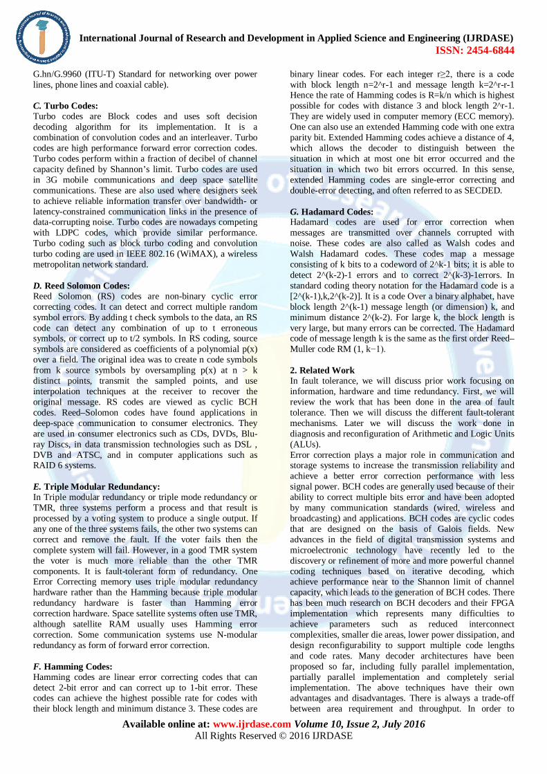
are combining our encoder and decoder circuits in a single part named as codec In this fig 4.3 we have generated the parallel data input along with manual error signal upto 6 bits and the circuit will correct the error and come out with the actual data we had given. In this fig 7 the two markers has been kept in White & Blue colour showing the Error Signals.
Fig. 7. BCH CODEC with error input
In this fig 8 we have introduced the error of more than 6 bits and we don't get desired output. In this fig 8 we have given input of Din: abcdef (Hex), Error: 0000000011111111 (Hex), Dout: EF89ab99(Hex).
Fig. 8. BCH CODEC with more than 6 bit error input
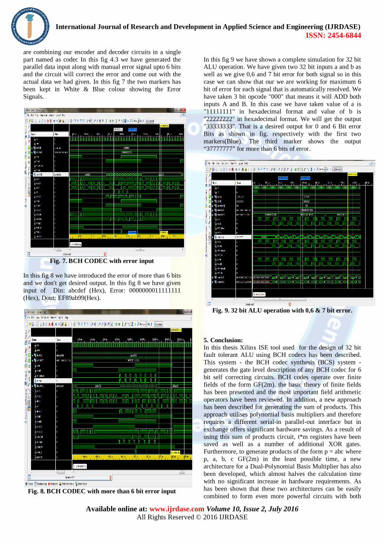
In this fig 9 we have shown a complete simulation for 32 bit ALU operation. We have given two 32 bit inputs a and b as well as we give 0,6 and 7 bit error for both signal so in this case we can show that our we are working for maximum 6 bit of error for each signal that is automatically resolved. We have taken 3 bit opcode "000" that means it will ADD both inputs A and B. In this case we have taken value of a is "11111111" in hexadecimal format and value of b is "22222222" in hexadecimal format. We will get the output "33333333". That is a desired output for 0 and 6 Bit error Bits as shown in fig. respectively with the first two markers(Blue). The third marker shows the output “37777777” for more than 6 bits of error.
Fig. 9. 32 bit ALU operation with 0,6 & 7 bit error.
5. Conclusion: In this thesis Xilinx ISE tool used for the design of 32 bit fault tolerant ALU using BCH codecs has been described. This system - the BCH codec synthesis (BCS) system - generates the gate level description of any BCH codec for 6 bit self correcting circuits. BCH codes operate over finite fields of the form GF(2m). the basic theory of finite fields has been presented and the most important field arithmetic operators have been reviewed. In addition, a new approach has been described for generating the sum of products. This approach utilises polynomial basis multipliers and therefore requires a different serial-in parallel-out interface but in exchange offers significant hardware savings. As a result of using this sum of products circuit, t*m registers have been saved as well as a number of additional XOR gates. Furthermore, to generate products of the form p = abc where p, a, b, c GF(2m) in the least possible time, a new architecture for a Dual-Polynomial Basis Multiplier has also been developed, which almost halves the calculation time with no significant increase in hardware requirements. As has been shown that these two architectures can be easily combined to form even more powerful circuits with both

International Journal of Research and Development in Applied Science and Engineering (IJRDASE) ISSN: 2454-6844
Available online at: www.ijrdase.com Volume 10, Issue 2, July 2016 All Rights Reserved © 2016 IJRDASE
low hardware requirements and high throughputs for use in the BMA. In addition, a simple way of constructing bit-parallel polynomial basis multipliers has been presented, and a circuit for raising finite field elements to the third power developed. References: [1] Fernanda Lima et. al, " Reducing Pin and Area Overhead in Fault-Tolerant FPGA based Designs ", FPGA’03, February 23-25, 2003, Monterey, California, USA. COPYRIGHT 2003 ACM 1-58113-651-X/03/0002… $5.00 [2] Fernanda Lima Kastensmidt et. al. "Designing and Testing Fault-Tolerant Techniques for SRAM-based FPGAs" CF’04, April 14–16, 2004, Ischia, Italy. Copyright 2004 ACM 1-58113-741-9/04/0004. [3] Jason a. cheathame et. al., " A Survey of Fault Tolerant Methodologies for FPGAs" ACM Transactions on Design Automation of Electronic Systems, Vol. 11, No. 2, April 2006, Pages 501–533. [4] Cristiana Bolchini et. al., " TMR and Partial Dynamic Reconfiguration to mitigate SEU faults in FPGAs" [5] Edward Stott et. al., " Fault Tolerant Methods For Reliability In FPGAs" 978-1-4244-1961-6/08/$25.00 ©2008 IEEE. [6] A. Vahid Khorasani et. al., "Analysis of 32-bit Fault Tolerant ALU Methods" 2010. [7] Martin Straka et.al., " Fault Tolerant Structure for SRAM-based FPGA via Partial Dynamic Reconfiguration" 2010. [8] Federico Baronti et.al., " Design and Verification of Hardware Building Blocks for High-Speed and Fault-Tolerant In-Vehicle Networks" IEEE transactions on industrial electronics, vol. 58, no. 3, march 2011. [9] Vahid Khorasani et.al., " Analyzing Area Penalty of 32-bit Fault Tolerant ALU Using BCH Code" 2011 14th Euromicro Conference on Digital System Design. [10] Mahadevaswamy V P et.al., " Implementation of Fault Tolerant Method Using BCH Code on FPGA" International Journal of Soft Computing and Engineering (IJSCE) ISSN: 2231-2307, Volume-2, Issue-4, September 2012 [11] D. A. Anderson. Design of Self-Checking Digital Networks Using Coding Techniques. Research Report # 527, Univ. of Illinois, Urbana Champaign, Coordinated Science Lab., September 1971. [12] A. Booth. A Signed Binary Multiplication Technique. Quarterly J. of Me- chanics and Applied Mathematics, 4(2):236{240, June 1951. [13] R. T. Brent and H. T. Kung. A Regular Layout for Parallel Adders. IEEE Trans. on Computers, C-31(3):260{264, March 1982. [14] L. Dadda. Some Schemes for Parallel Multipliers. Alta Frequenza, 34(5):349{ 356, May 1965. [15] P. M. Kogge and H. S. Stone. A Parallel Algorithm for the Efficient Solution of a General Class of Recurrence Equations. IEEE Trans. on Computers, C-22(8):786{792, August 1973. [16] D. Patil, O. Azizi, M. Horowitz, R. Ho, and R. Ananthraman. Robust Energy-Efficient Adder Topologies. In ARITH '07: Proceedings of the 18th IEEE Symposium on Computer Arithmetic, pages 16{28, Washington, DC, USA, June 2007. IEEE Computer Society.
[17] J. Sklansky. Conditional-Sum Addition Logic. IRE Trans. on Electronic Computers, EC-9(2):226{231, June 1960.