Embed Size (px)
Citation preview

Research Article Impact Factor: 4.226 ISSN: 2319-507X Tejas Rathi , IJPRET, 2014; Volume 3 (4): 115-128 IJPRET
Available Online at www.ijpret.com
115
INTERNATIONAL JOURNAL OF PURE AND APPLIED RESEARCH IN ENGINEERING AND
TECHNOLOGY A PATH FOR HORIZING YOUR INNOVATIVE WORK
STATIC, DYNAMIC AND FATIGUE ANALYSIS OF COMPOSITE LEAF SPRING FOR
LIGHT WEIGHT VEHICLE
MR.TEJAS RATHI1, PROF. CHANDRESH MOTKA2, PROF. DHAVAL P. PATEL3 1. Student, Mechanical Engineering Department, Kalol Institute of Technology and Research Centre, Kalol, GTU.
2. Assistant Professor, Mechanical Engineering Department, Kalol Institute of Technology and Research Centre, Kalol, GTU.
3. Assistant Professor, Mechanical Engineering Department, Gandhinagar Institute of Technology, Moti Bhoyan, GTU.
Accepted Date: 24/10/2014; Published Date: 01/11/2014
\
Abstract: To describe design and experimental analysis of composite leaf spring made of glass fiber reinforced polymer or other material base on light weight vehicle. The objective is to compare the load carrying capacity, stiffness and weight savings of composite leaf spring with that of steel leaf spring. The design constraints are stresses and deflections. The dimensions of an existing conventional steel leaf spring of a light commercial vehicle are taken. Same dimensions of conventional leaf spring are used to fabricate a composite multi leaf spring using Glass/Epoxy unidirectional laminates. Modeling of leaf spring is done in Solid Works 2011. Static analysis of 2-D model of conventional leaf spring is also performed using ANSYS. Finite element analysis with full load on 3-D model of composite multi leaf spring is done using ANSYS by taking two different material structural steel and E-Glass/Epoxy. Also done dynamic analysis of multi leaf spring for frequency analyses in different modal form of leaf spring. Compare both result of von misses stress, total shear stress and total deflection in static condition for both material. Keywords: Composite leaf spring, Weight, Stress, Deflection, Stiffness, Solid Works.
Corresponding Author: MR. TEJAS RATHI
Access Online On:
www.ijpret.com
How to Cite This Article:
Tejas Rathi, IJPRET, 2014; Volume 3 (4): 115-128
PAPER-QR CODE
Research Article Impact Factor: 4.226 ISSN: 2319-507X Tejas Rathi , IJPRET, 2014; Volume 3 (4): 115-128 IJPRET
Available Online at www.ijpret.com
116
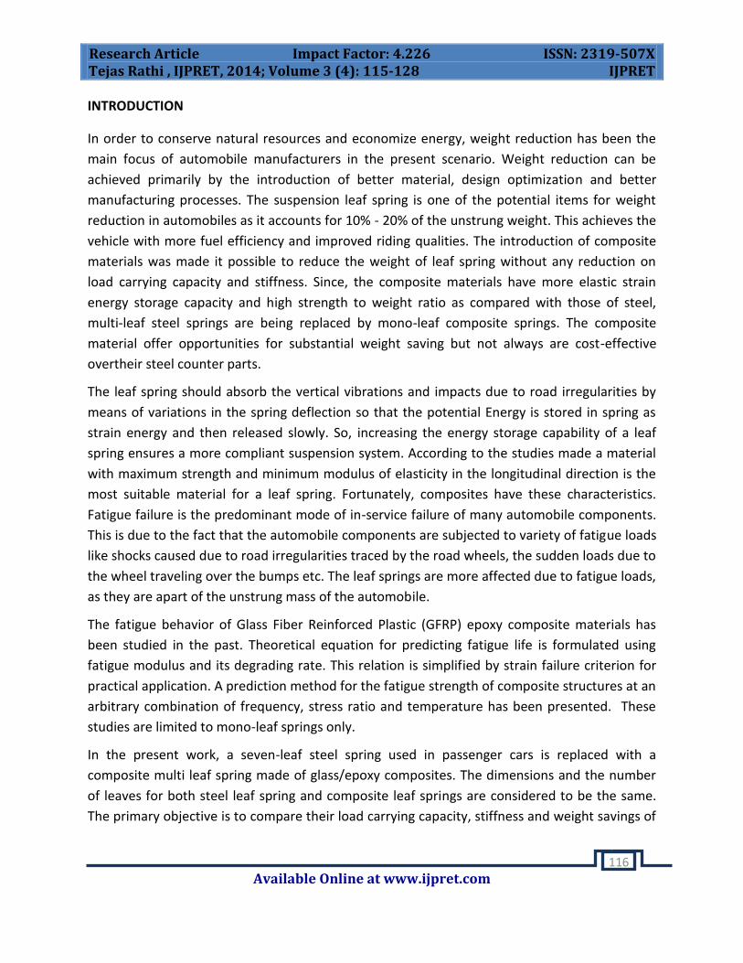
INTRODUCTION
In order to conserve natural resources and economize energy, weight reduction has been the
main focus of automobile manufacturers in the present scenario. Weight reduction can be
achieved primarily by the introduction of better material, design optimization and better
manufacturing processes. The suspension leaf spring is one of the potential items for weight
reduction in automobiles as it accounts for 10% - 20% of the unstrung weight. This achieves the
vehicle with more fuel efficiency and improved riding qualities. The introduction of composite
materials was made it possible to reduce the weight of leaf spring without any reduction on
load carrying capacity and stiffness. Since, the composite materials have more elastic strain
energy storage capacity and high strength to weight ratio as compared with those of steel,
multi-leaf steel springs are being replaced by mono-leaf composite springs. The composite
material offer opportunities for substantial weight saving but not always are cost-effective
overtheir steel counter parts.
The leaf spring should absorb the vertical vibrations and impacts due to road irregularities by
means of variations in the spring deflection so that the potential Energy is stored in spring as
strain energy and then released slowly. So, increasing the energy storage capability of a leaf
spring ensures a more compliant suspension system. According to the studies made a material
with maximum strength and minimum modulus of elasticity in the longitudinal direction is the
most suitable material for a leaf spring. Fortunately, composites have these characteristics.
Fatigue failure is the predominant mode of in-service failure of many automobile components.
This is due to the fact that the automobile components are subjected to variety of fatigue loads
like shocks caused due to road irregularities traced by the road wheels, the sudden loads due to
the wheel traveling over the bumps etc. The leaf springs are more affected due to fatigue loads,
as they are apart of the unstrung mass of the automobile.
The fatigue behavior of Glass Fiber Reinforced Plastic (GFRP) epoxy composite materials has
been studied in the past. Theoretical equation for predicting fatigue life is formulated using
fatigue modulus and its degrading rate. This relation is simplified by strain failure criterion for
practical application. A prediction method for the fatigue strength of composite structures at an
arbitrary combination of frequency, stress ratio and temperature has been presented. These
studies are limited to mono-leaf springs only.
In the present work, a seven-leaf steel spring used in passenger cars is replaced with a
composite multi leaf spring made of glass/epoxy composites. The dimensions and the number
of leaves for both steel leaf spring and composite leaf springs are considered to be the same.
The primary objective is to compare their load carrying capacity, stiffness and weight savings of

Research Article Impact Factor: 4.226 ISSN: 2319-507X Tejas Rathi , IJPRET, 2014; Volume 3 (4): 115-128 IJPRET
Available Online at www.ijpret.com
117
composite leaf spring. Finally, fatigue life of steel and composite leaf spring is also predicted
using life data.
[1] ANALYTICAL CALCULATION AND CAD MODELLING OFCOMPOSITE LEAF SPRING
A spring is defined as an elastic body, whose function is to distort when loaded and to recover
its original shape when the load is removed. Leaf springs absorb the vehicle vibrations, shocks
and bump loads (induced due to road irregularities) by means of spring deflections, so that the
potential energy is stored in the leaf spring and then relieved slowly [1]. Ability to store and
absorb more amount of strain energy ensures the comfortable suspension system. Semi-elliptic
leaf springs are almost universally used for suspension in light and heavy commercial vehicles.
For cars also, these are widely used in rear suspension. The spring consists of a number of
leaves called blades. The blades are varying in length. The blades are us usually given an initial
curvature or cambered so that they will tend to straighten under the load. The leaf spring is
based upon the theory of a beam of uniform strength. The lengthiest blade has eyes on its
ends. This blade is called main or master leaf, the remaining blades are called graduated leaves.
All the blades are bound together by means of steel straps.
The spring is mounted on the axle of the vehicle. The entire vehicle load rests on the leaf spring.
The front end of the spring is connected to the frame with a simple pin joint, while the rear end
of the spring is connected with a shackle. Shackle is the flexible link which connects between
leaf spring rear eye and frame. When the vehicle comes across a projection on the road surface,
the wheel moves up, leading to deflection of the spring. This changes the length between the
spring eyes. If both the ends are fixed, the spring will not be able to accommodate this change
of length. So, to accommodate this change in length shackle is provided at one end, which gives
a flexible connection. The front eye of the leaf spring is constrained in all the directions, where
as rear eye is not constrained in X-direction. This rare eye is connected to the shackle. During
loading the spring deflects and moves in the direction perpendicular to the load applied.
When the leaf spring deflects, the upper side of each leaf tips slides or rubs against the lower
side of the leaf above it. This produces some damping which reduces spring vibrations, but
since this available damping may change with time, it is preferred not to avail of the same.
Moreover, it produces squeaking sound. Further if moisture is also present, such inter-leaf
friction will cause fretting corrosion which decreases the fatigue Strength of the spring,
phosphate paint may reduce this problem fairly. The elements of leaf spring are shown in
Figure 3.1. Where t is the thickness of the plate, b is the width of the plate and L is the length of
plate or distance of the load W from the cantilever end.

Research Article Impact Factor: 4.226 ISSN: 2319-507X Tejas Rathi , IJPRET, 2014; Volume 3 (4): 115-128 IJPRET
Available Online at www.ijpret.com
118
Fig. 1 Elements of Leaf Spring
[2] Bending Stress of Leaf Spring
Leaf springs (also known as flat springs) are made out of flat plates. The advantage of leaf
spring over helical spring is that the ends of the spring may be guided along a definite path as it
deflects to act as a structural member in addition to energy absorbing device. Thus the leaf
springs may carry lateral loads, brake torque, driving torque etc., in addition to shocks. Consider
a single plate fixed at one end and loaded at the other end. This plate may be used as a flat
spring.
Let t = thickness of plate
b = width of plate, and
L = length of plate or distance of the load W from the cantilever end, as shown in the Figure 1.
We know that the maximum bending moment at the cantilever end
M = W.L
And section modulus,
Z = I/y
Where I = (b.t3 / 12) and Y = t/2
So Z = b.t2 / 6
The bending stress in such a spring,
f = M / Z = (6W.L) / b.t2------------------- (i)
We know that the maximum deflection for a cantilever with concentrated load at free end is
given by
δ = W.L3 / 3.E.I = 2f.L2 / 3.E.t---------------- (ii)

Research Article Impact Factor: 4.226 ISSN: 2319-507X Tejas Rathi , IJPRET, 2014; Volume 3 (4): 115-128 IJPRET
Available Online at www.ijpret.com
119
It may be noted that due to bending moment, top fibers will be in tension and bottom fibers
are in compression, but the shear stress is zero at the extreme fibers and the maximum at
centre, hence for analysis, both stresses need not to be taken into account simultaneously. We
shall consider bending stress only.
If the spring is not of cantilever type but it is like a simply supported beam, with length 2L and
load2W in the centre
Maximum bending moment in the centre,
M = W.L
Section modulus
Z = b.t2 / 6
Bending stress
f = 6W.L /b.t2
We know that maximum deflection of a simply supported beam loaded in the centre is given by
δ = W.L3 / 3.E.I
From above we see that a spring such as automobile spring (semi-elliptical spring) with length
2L and load in the centre by a load 2W may be treated as double cantilever. If the plate of
cantilever is cut into a series of n strips of width b and these are placed as shown in Figure 1,
then equations (i) and (ii) may be written as
f = 6W.L / n.b.t2---------------- (iii)
δ = 4.W.L3 / n.E.b.t3 = 2.f.L2 /3.E.t---------------- (iv)
The above relation gives the bending stress of a leaf spring of uniform cross- section and is
given in Table 1 at various loads. The stress at such a spring is maximum at support.
Table 1 Variation of Bending Stress and Deflection with load
Sr. No. Load (W) in N Bending Stress (f) in N/mm2 Deflection (δ) in mm
1 1000 187 31.0
2 2000 373 61.9
3 3000 560 92.9
4 4000 747 123.9
5 5000 933 154.9
Research Article Impact Factor: 4.226 ISSN: 2319-507X Tejas Rathi , IJPRET, 2014; Volume 3 (4): 115-128 IJPRET
Available Online at www.ijpret.com
120
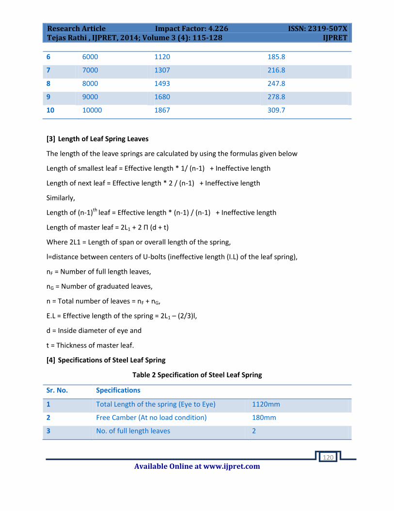
6 6000 1120 185.8
7 7000 1307 216.8
8 8000 1493 247.8
9 9000 1680 278.8
10 10000 1867 309.7
[3] Length of Leaf Spring Leaves
The length of the leave springs are calculated by using the formulas given below
Length of smallest leaf = Effective length * 1/ (n-1) + Ineffective length
Length of next leaf = Effective length * 2 / (n-1) + Ineffective length
Similarly,
Length of (n-1)th leaf = Effective length * (n-1) / (n-1) + Ineffective length
Length of master leaf = 2L1 + 2 Π (d + t)
Where 2L1 = Length of span or overall length of the spring,
l=distance between centers of U-bolts (ineffective length (I.L) of the leaf spring),
nF = Number of full length leaves,
nG = Number of graduated leaves,
n = Total number of leaves = nF + nG,
E.L = Effective length of the spring = 2L1 – (2/3)l,
d = Inside diameter of eye and
t = Thickness of master leaf.
[4] Specifications of Steel Leaf Spring
Table 2 Specification of Steel Leaf Spring
Sr. No. Specifications
1 Total Length of the spring (Eye to Eye) 1120mm
2 Free Camber (At no load condition) 180mm
3 No. of full length leaves 2

Research Article Impact Factor: 4.226 ISSN: 2319-507X Tejas Rathi , IJPRET, 2014; Volume 3 (4): 115-128 IJPRET
Available Online at www.ijpret.com
121
4 No. of graduated leaves 8
5 Thickness of leaf 6mm
6 Width of leaf spring 50mm
7 Maximum Load given on spring 6685N
8 Young’s Modulus of the steel 210000 (MPa)
9 Weight of the leaf spring 17.78 kg
10 Poisson’s ratio 0.3
[5] Solid Modeling
In multi-leaf steel spring and mono-composite leaf spring are modeled. For modeling the steel
spring, the dimensions of a conventional leaf spring of a light weight commercial vehicle
are chosen. Since the leaf spring is symmetrical about the neutral axis only half of the
leaf spring is modeled by considering it as a cantilever beam and a uniformly distributed
load is applied over the ineffective length of the leaf spring in the upward direction.
Fig 2 Leaf Spring Drawing

Research Article Impact Factor: 4.226 ISSN: 2319-507X Tejas Rathi , IJPRET, 2014; Volume 3 (4): 115-128 IJPRET
Available Online at www.ijpret.com
122
Fig 3 Leaf Spring Assembly Drawing
Fig 4 Solid model of steel leaf spring created in Solid Work 2011 and imported it’s for analysis
in ANSYS
[6] Assumptions
All non-linear effects are excluded.
The stress-strain relationship for composite material is linear and elastic; hence Hooke’s law
is applicable for composite materials
The leaf spring is assumed to be in vacuum.
The load is distributed uniformly at the middle of the leaf spring.
The leaf spring has a uniform, rectangular cross section.
[7] Selection of Cross Section

Research Article Impact Factor: 4.226 ISSN: 2319-507X Tejas Rathi , IJPRET, 2014; Volume 3 (4): 115-128 IJPRET
Available Online at www.ijpret.com
123
The following cross-sections of mono-leaf spring for manufacturing easiness are considered.
Constant thickness, varying width design
Varying width, varying thickness design.
Constant thickness, constant width design
In the present work, only constant cross-section design method is selected due to the following
reasons: due to its capability for mass production and accommodation of continuous
reinforcement of fibers. Since the cross-section area is constant throughout the leaf spring,
same quantity of reinforcement fiber and resin can be fed continuously during manufacturing.
[8] Materials for Leaf Spring
The material used for leaf springs is usually a plain carbon steel having 0.90 to 1.0% carbon. The
leaves are heat treated after the forming process. The heat treatment of spring steel products
greater strength and therefore greater load capacity, greater range of deflection and better
fatigue properties.
Material Properties:
Name : Mild steel
Yield strength: 5.5e+008N/m2
Tensile strength: 3e+007 N/m2
Elastic modulus: 2.6e+011 N/m2
Poisson’s ratio: 0.266
Density : 7860kg/m3
Shear modulus: 30189e+008N/m2
Chemical Composition: EN 45 Materials
Table 3 Chemical Composition of EN 45 Materials
%C %Si % Mn %S %P
0.50/0.60 1.50/2.00 0.70/1.00 0.050 0.050
Carbon/Graphite fibers: Their advantages include high specific strength and modulus, low
coefficient of thermal expansion and high fatigue strength. Graphite, when used alone has low

Research Article Impact Factor: 4.226 ISSN: 2319-507X Tejas Rathi , IJPRET, 2014; Volume 3 (4): 115-128 IJPRET
Available Online at www.ijpret.com
124
impact resistance. Its drawbacks include high cost, low impact resistance and high electrical
conductivity.
Glass fibers: The main advantage of Glass fiber over others is its low cost. It has high
strength, high chemical resistance and good insulating properties. The disadvantages are low
elastic modulus poor adhesion to polymers, low fatigue strength and high density, which
increase leaf spring weight and size. Also crack detection becomes difficult.
[9] E-Glass/Epoxy:
Table 4 Material properties of E-Glass/Epoxy
Sr.
No.
Properties Value
1 Tensile modulus along X-direction (Ex), MPa 34000
2 Tensile modulus along Y-direction (Ey), MPa 6530
3 Tensile modulus along Z-direction (Ez), MPa 6530
4 Tensile strength of the material, MPa 900
5 Compressive strength of the material, MPa 450
6 Shear modulus along XY-direction (Gxy), MPa 2433
7 Shear modulus along YZ-direction (Gyz), MPa 1698
8 Shear modulus along ZX-direction (Gzx), MPa 2433
9 Poisson ratio along XY-direction (NUxy) 0.217
10 Poisson ratio along YZ-direction (NUyz) 0.366
11 Poisson ratio along ZX-direction (NUzx) 0.217
12 Mass density of the material (ρ), kg/mm3 2.6e-6
13 Flexural modulus of the material, MPa 40000
14 Flexural strength of the material, MPa 1200
[10] Specific Design Data
Here Weight and initial measurements of Mahindra “Model - commander 650 di” light vehicle
are taken
Gross vehicle weight = 2150 kg

Research Article Impact Factor: 4.226 ISSN: 2319-507X Tejas Rathi , IJPRET, 2014; Volume 3 (4): 115-128 IJPRET
Available Online at www.ijpret.com
125
Unspring weight = 240 kg
Total sprung weight = 1910 kg
Taking factor of safety (FS) = 1.4
Acceleration due to gravity (g) = 10 m/s²
There for; Total Weight (W) = 1910*10*1.4 = 26740 N
Since the vehicle is 4-wheeler, a single leaf spring corresponding to one of the wheels
takes up one fourth of the total weight.
F = 26740/4 = 6685 N
[11] Design Parameters of Steel Leaf Spring
Table 5 Design Parameter of Steel Leaf Spring
Leaf no. Full leaf length (mm)
2L
Half leaf length(mm) L
Radius of curvature
R (mm)
1 1120 560 961.11
2 1120 560 967.11
3 1007 503.5 973.11
4 894 447 979.11
5 780 390 985.11
6 667 333.5 991.11
7 554 277 997.11
8 440 220 1003.11
9 327 163.5 1009.11
10 214 107 1015.11
Since the leaf spring is fixed with the axle at its center, only half of it is considered for analysis
purpose with half load.

Research Article Impact Factor: 4.226 ISSN: 2319-507X Tejas Rathi , IJPRET, 2014; Volume 3 (4): 115-128 IJPRET
Available Online at www.ijpret.com
126
[12] Static Analysis
Table 6 Comparison of Static Analysis Result
Material Von-mises stress
(MPa)
Max. Shear Stress
(MPa)
Total Deflection
(mm)
Structural
Steel(EN45)
126.44 21.96 37621
E-Glass/Epoxy 126.99 23.07 22128
[13] DYNAMic Analysis
The table show modal analysis of Leaf Spring which having material EN 45 containing different
six mode of defamation.
Mode Frequency Hz
1 71.612
2 138.94
3 305.44
4 307.44
5 631.4
6 648.69
The table show modal analysis of Leaf Spring which having material E-PROXY containing
different six mode of defamation.
Mode Frequency Hz
1 83.037
2 151.9
3 338.14
4 350.3
5 670.15

Research Article Impact Factor: 4.226 ISSN: 2319-507X Tejas Rathi , IJPRET, 2014; Volume 3 (4): 115-128 IJPRET
Available Online at www.ijpret.com
127
6 713.65
[14] FAtiGUE Analysis
Table 7 Comparison of Fatigue Analysis Result
Sr.
No.
Material Life
1X10⁹
(Minimum)
Damage
Life 1X10⁹
(Maximum)
Safety Factor
(Minimum)
Fatigue Sensitivity
(Nos. of Fill Point)
1 Structural Steel 20.797 Cycles 4.8085 X 10⁷ 0.031015 50-150% (25)
2 E Glass/Epoxy 1.3521 X 10⁵
Cycle
7395.7 0.6788
50-150% (25)
ACKNOWLEDGMENT
It is indeed a great pleasure for me to express my sincere gratitude to those who have always
helped me for this dissertation work.
I am extremely thankful to my thesis guide Prof. Chandresh Motka, Professor in Mechanical
Engineering Department, Kalol Institute of Technology and Research Centre, Kalol are valuable
guidance, motivation, cooperation, constant support with encouraging attitude at all stages of
my work.
CONCLUSION
In this study, the response of Composite Leaf Spring is determined input parameter identified.
Basic design calculation of multi leaf spring includes different parameter of Composite Leaf
Spring identified and calculation represent basic component‘s parameter geometric constraint
form.
The analysis performed in this research is based on some assumptions and restrictions.
However, complete literature review and input parameter of Composite Leaf Spring
identification, thus, understanding of behavior of Composite Leaf Spring is attained taking every
possible detail into account.
Research Article Impact Factor: 4.226 ISSN: 2319-507X Tejas Rathi , IJPRET, 2014; Volume 3 (4): 115-128 IJPRET
Available Online at www.ijpret.com
128
REFERENCES
1. W. A. Hufenbach, P. Kostka, B. Maron, D. Weck, J. Ehlig, M. Gude, M. Zscheyge,”
Development and investigation of a textile-reinforced thermoplastic leaf spring with integrated
sensor networks”, Procedia Materials Science 2 (2013) 173 – 180.
2. Dipendra Kumar Royaand KashiNathSahab, “Nonlinear Analysis of Leaf Springs of
Functionally Graded Materials”,Procedia Engineering 51 (2013) 538 – 543.
3. Yeon-GwanLeea, Dae-Hyun Kimb, Chun-GonKima, ‘’ Design of patterned leaf spring for
sensor-probe with stable reflectivityand high sensitivity”, Sensors and Actuators A 176
(2012) 19– 26.
4. AL-Qureshi, H. A., “Automobile leaf springs from composite materials”, Journal of Materials
Processing Technology 118 (2011) 58-61.
5. J.P. Houa,J.Y. Cherruaultb, I. Nairneb, G. Jeronimidisa, R.M. Mayerb, “Evolution of the eye-
end design of a composite leaf springfor heavy axle loads”,Composite Structures 78 (2007) 351–
358.
6. E. Mahdia, O.M.S. Alkolesa, A.M.S. Hamoudab, B.B. Saharib, R. Yonusc, G. Goudaha,”Light
composite elliptic springs for vehicle suspension”, Composite Structures 75 (2006) 24–28.
7. Mahmood M. Shokrieh, DavoodRezaei,” Analysis and optimization of a composite leaf
spring”, Composite Structures 60 (2003) 317–325.
8. I. Rajendran,S. Vijayarangan,“Optimal design of a composite leaf spring using genetic
algorithms”, Computers and Structures 79 (2001) 1121-1129.
9. P. Beardmore, Composite structure for automobiles, 1986.
10. R.S. Khurmi, J.K. Kupta. A text book of Machine Design, 2000.
11. R. M. Jones, Mechanics of Composite Materials. 2e, McGraw-Hill Book Company, 1990.
12. K. Tanabe, T. Seino, Y. Kajio, Characteristics of Carbon/Glass Fiber Reinforced Plastic Leaf
Spring, 1982.