Embed Size (px)
Citation preview
3448
Published On: 31ST May, 2016
Available online through - http://ijifr.com/searchjournal.aspx
www.ijifr.com
International Journal of Informative & Futuristic Research ISSN: 2347-1697
Volume 3 Issue 9 May 2016 Research Paper
Abstract
Computation of potential and electrical field strength along the insulator strings is an important aspect for their designs. Similar with porcelain insulator strings, the axial potential distribution of composite insulator strings is non-uniform. Based on the characteristics of capacitive electric field distribution of composite insulators, this paper presents a new measure to improve electric field distribution based Ceramic insulators are widely used in power transmission lines to provide mechanical support for High voltage conductors in addition to withstand electrical stresses. As a result of lightning, switching or temporary over voltages that could initiate flashover under worst weather conditions, and to operate within interference limits. Given that the useful life in service of the individual insulator elements making up the insulator strings is hard to predict, they must be verified periodically to ensure that adequate line reliability is maintained at all times Due to deficiency of electric field data for the existing string configuration, utilities are forced to replace the discs
Simulation Of Potential And Electric Field
Distribution For Different Parts Of Insulator
Using Finite Element Method Paper ID IJIFR/V3/ E9/ 056 Page No. 3448-3454 Subject Area
Electrical &
Electronics Engg.
KeyWords Insulator, CATIA, Hypermesh, ANSYS, FEM
1st Sulthan Mohyuddin
Associate Professor
Department of Electrical and Electronics Engineering
Srinivas Institute of Technology
Valachil, Mangalore-Karnataka
2nd Harshith K
Assistant Professor
Department of Electrical and Electronics Engineering
Srinivas Institute of Technology
Valachil, Mangalore-Karnataka
3rd Nazma S Assistant Professor
Department of Electronics & Comm. Engineering
Srinivas Institute of Technology
Valachil, Mangalore-Karnataka 4th Kripa K B
3449
ISSN: 2347-1697
International Journal of Informative & Futuristic Research (IJIFR)
Volume - 3, Issue -9, May 2016
Continuous 33rd Edition, Page No.: 3448-3454
Sulthan Mohyuddin, Harshith K, Nazma S, Kripa K B:: Simulation Of Potential And Electric Field Distribution For Different Parts Of Insulator Using Finite Element Method
which may not be essentially required. Hence, effort is made in the present work to simulate the potential and electric field along the normal and with faults induced discs. This study is concerned with the voltage and the electric field distribution on a ceramic disc insulator of insulator type suspension strings composed of cap and pin type porcelain insulators. It’s one of the main structure utilize for the better operation of insulator. Finite Element Method based software, CATIA and HYPERMESH, was used three dimensional modeling and simulations.
1. INTRODUCTION
Control of electrical field distribution within and around high voltage equipment is one of
the basic aspects of the design of such equipment. Audible noise, radio noise, partial
discharges and corona discharges are some of the possible results of high level electrical
fields. Modern society exclusively depends on the electrical power for industrial,
commercial, agricultural, domestic and social purposes. The electrical energy is generated
mainly at the hydro, thermal and nuclear power stations. Due to various reasons, the
generating stations and the load centers are geographically far off, which necessitates
transmission of bulk power over long distances. This important task at present is mostly
performed by overhead power transmission lines. Currently, underground transmission is
also employed however; capacitive charging current of the cable limits its application to
shorter distances. In a dry and clean state, the voltage distribution of a composite insulator
string is characterized by a capacitive distribution. According to Kirchhoff’s law, if a composite insulator circuit is placed in a series with capacitors, resistors, or inductors, the
voltage of the composite insulator can be assumed to be significantly improved.
2. IDENTIFICATION OF NUMERICAL TECHNIQUES
Due to the sensitivity of insulating materials to electric field, accurate determination of
electric field is necessary while designing and diagnostics of high voltage apparatus.
Various numerical methods have been employed over the years for the computation of the
electric potential and field along the insulator string. Basically there are two methods,
Domain based methods and Boundary based methods. Finite Difference Method (FDM)
and Finite Element Method comes under Domain based methods, and Boundary based
methods includes Boundary Element Method (BEM), Charge Simulation Method (CSM)
and Surface Charge Simulation Method (SCSM).
3. DESCRIPTION OF EXISTING PROBLEMS
Although the EFPD along the ceramic insulators has been widely studied for a long time,
the results of these studies cannot be applied directly to the real power line insulators. The
limitations of the previous studies are: The analysis of the EFPD along ceramic insulators
usually assumes single phase energization. However, a real power line means three phase
energization, and the presence of the other two phases may have some influence on the
EFPD along a ceramic insulator.
3450
ISSN: 2347-1697
International Journal of Informative & Futuristic Research (IJIFR)
Volume - 3, Issue -9, May 2016
Continuous 33rd Edition, Page No.: 3448-3454
Sulthan Mohyuddin, Harshith K, Nazma S, Kripa K B:: Simulation Of Potential And Electric Field Distribution For Different Parts Of Insulator Using Finite Element Method
4. LAPLACE EQUATION AND MODEL
Calculation of electric fields requires solution of Laplace's eqn. and Poisson’s equation eqn. with boundary conditions satisfied. This can be done either by analytical or numerical
methods. ∇ � = −�/� (1)
……………. ∇ � = (2)
………
In eqns. the operator ∇ is called the laplacian and is a vector with properties
∇. ∇ = ∇ = ∂2∂x2 + ∂2∂ 2 + ∂2∂ 2 (3)
The energy per unit length associated with the element is given by the following equation:
� =1/2 �[ �]�[� � ][ �] … ( (4)
Where, T denotes the transpose of the matrix
[Ve] = [ ��� ] And [� � ] = [� � � � � �� � � � � �� � � � � � ] (5)
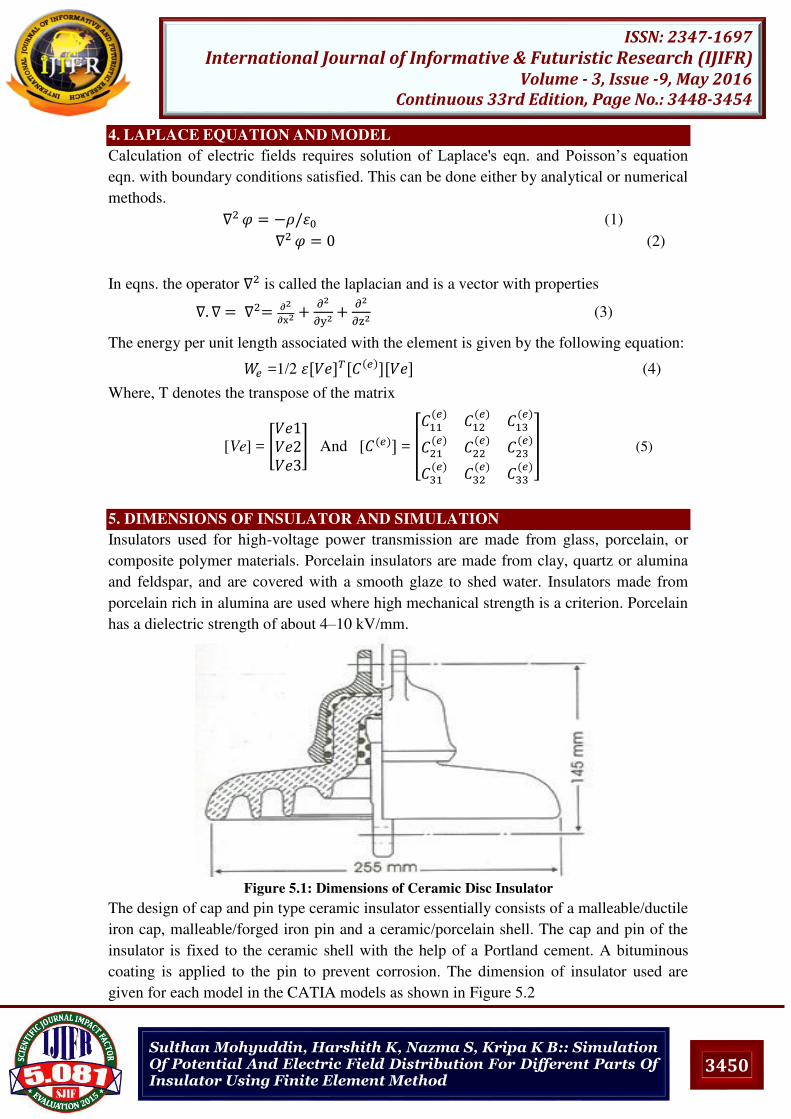
5. DIMENSIONS OF INSULATOR AND SIMULATION
Insulators used for high-voltage power transmission are made from glass, porcelain, or
composite polymer materials. Porcelain insulators are made from clay, quartz or alumina
and feldspar, and are covered with a smooth glaze to shed water. Insulators made from
porcelain rich in alumina are used where high mechanical strength is a criterion. Porcelain
has a dielectric strength of about 4–10 kV/mm.
Figure 5.1: Dimensions of Ceramic Disc Insulator
The design of cap and pin type ceramic insulator essentially consists of a malleable/ductile
iron cap, malleable/forged iron pin and a ceramic/porcelain shell. The cap and pin of the
insulator is fixed to the ceramic shell with the help of a Portland cement. A bituminous
coating is applied to the pin to prevent corrosion. The dimension of insulator used are
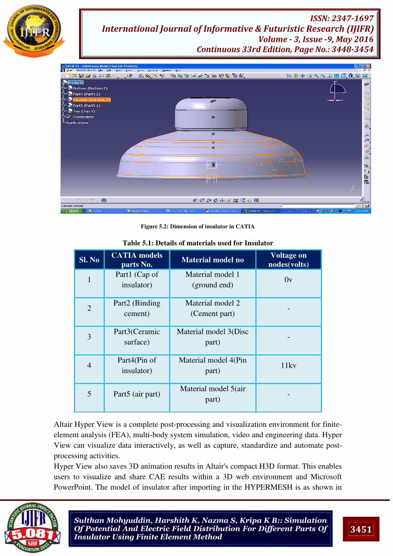
given for each model in the CATIA models as shown in Figure 5.2
3451
ISSN: 2347-1697
International Journal of Informative & Futuristic Research (IJIFR)
Volume - 3, Issue -9, May 2016
Continuous 33rd Edition, Page No.: 3448-3454
Sulthan Mohyuddin, Harshith K, Nazma S, Kripa K B:: Simulation Of Potential And Electric Field Distribution For Different Parts Of Insulator Using Finite Element Method
Figure 5.2: Dimension of insulator in CATIA
Table 5.1: Details of materials used for Insulator
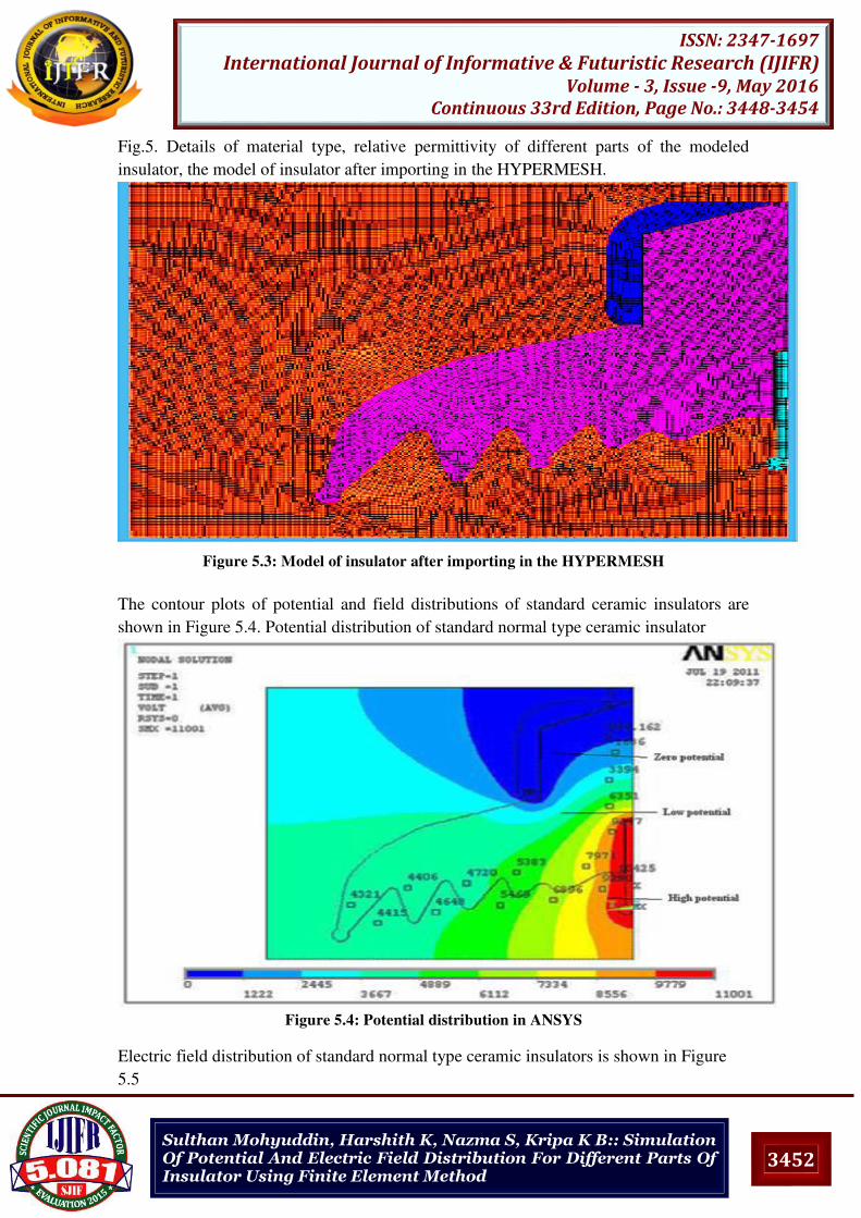
Altair Hyper View is a complete post-processing and visualization environment for finite-
element analysis (FEA), multi-body system simulation, video and engineering data. Hyper
View can visualize data interactively, as well as capture, standardize and automate post-
processing activities.
Hyper View also saves 3D animation results in Altair's compact H3D format. This enables
users to visualize and share CAE results within a 3D web environment and Microsoft
PowerPoint. The model of insulator after importing in the HYPERMESH is as shown in
Sl. No CATIA models
parts No. Material model no
Voltage on
nodes(volts)
1 Part1 (Cap of
insulator)
Material model 1
(ground end) 0v
2 Part2 (Binding
cement)
Material model 2
(Cement part) -
3 Part3(Ceramic
surface)
Material model 3(Disc
part) -
4 Part4(Pin of
insulator)
Material model 4(Pin
part) 11kv
5 Part5 (air part) Material model 5(air
part) -
3452
ISSN: 2347-1697
International Journal of Informative & Futuristic Research (IJIFR)
Volume - 3, Issue -9, May 2016
Continuous 33rd Edition, Page No.: 3448-3454
Sulthan Mohyuddin, Harshith K, Nazma S, Kripa K B:: Simulation Of Potential And Electric Field Distribution For Different Parts Of Insulator Using Finite Element Method
Fig.5. Details of material type, relative permittivity of different parts of the modeled
insulator, the model of insulator after importing in the HYPERMESH.
Figure 5.3: Model of insulator after importing in the HYPERMESH
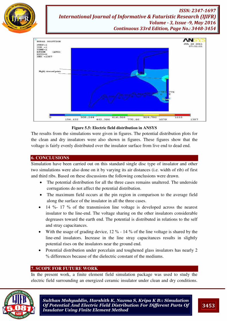
The contour plots of potential and field distributions of standard ceramic insulators are
shown in Figure 5.4. Potential distribution of standard normal type ceramic insulator
Figure 5.4: Potential distribution in ANSYS
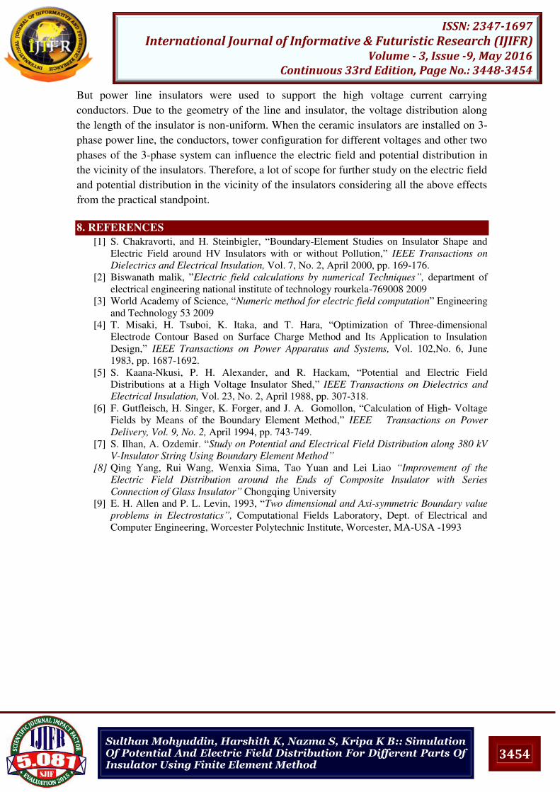
Electric field distribution of standard normal type ceramic insulators is shown in Figure
5.5
3453
ISSN: 2347-1697
International Journal of Informative & Futuristic Research (IJIFR)
Volume - 3, Issue -9, May 2016
Continuous 33rd Edition, Page No.: 3448-3454
Sulthan Mohyuddin, Harshith K, Nazma S, Kripa K B:: Simulation Of Potential And Electric Field Distribution For Different Parts Of Insulator Using Finite Element Method
Figure 5.5: Electric field distribution in ANSYS
The results from the simulations were given in figures. The potential distribution plots for
the clean and dry insulators were also shown in figures. These figures show that the
voltage is fairly evenly distributed over the insulator surface from live end to dead end.
6. CONCLUSIONS
Simulation have been carried out on this standard single disc type of insulator and other
two simulations were also done on it by varying its air distances (i.e. width of rib) of first
and third ribs. Based on these discussions the following conclusions were drawn.
The potential distribution for all the three cases remains unaltered. The underside
corrugations do not affect the potential distribution.
The maximum field occurs at the pin region in comparison to the average field
along the surface of the insulator in all the three cases.
14 %- 17 % of the transmission line voltage is developed across the nearest
insulator to the line-end. The voltage sharing on the other insulators considerable
degreases toward the earth end. The potential is distributed in relations to the self
and stray capacitances.
With the usage of grading device, 12 % - 14 % of the line voltage is shared by the
line-end insulators. Increase in the line stray capacitances results in slightly
potential rises on the insulators near the ground end.
Potential distribution under porcelain and toughened glass insulators has nearly 2
% differences because of the dielectric constant of the mediums.
7. SCOPE FOR FUTURE WORK In the present work, a finite element field simulation package was used to study the
electric field surrounding an energized ceramic insulator under clean and dry conditions.
3454
ISSN: 2347-1697
International Journal of Informative & Futuristic Research (IJIFR)
Volume - 3, Issue -9, May 2016
Continuous 33rd Edition, Page No.: 3448-3454
Sulthan Mohyuddin, Harshith K, Nazma S, Kripa K B:: Simulation Of Potential And Electric Field Distribution For Different Parts Of Insulator Using Finite Element Method
But power line insulators were used to support the high voltage current carrying
conductors. Due to the geometry of the line and insulator, the voltage distribution along
the length of the insulator is non-uniform. When the ceramic insulators are installed on 3-
phase power line, the conductors, tower configuration for different voltages and other two
phases of the 3-phase system can influence the electric field and potential distribution in
the vicinity of the insulators. Therefore, a lot of scope for further study on the electric field
and potential distribution in the vicinity of the insulators considering all the above effects
from the practical standpoint.
8. REFERENCES
[1] S. Chakravorti, and H. Steinbigler, “Boundary-Element Studies on Insulator Shape and
Electric Field around HV Insulators with or without Pollution,” IEEE Transactions on
Dielectrics and Electrical Insulation, Vol. 7, No. 2, April 2000, pp. 169-176.
[2] Biswanath malik, ”Electric field calculations by numerical Techniques”, department of
electrical engineering national institute of technology rourkela-769008 2009
[3] World Academy of Science, “Numeric method for electric field computation” Engineering
and Technology 53 2009
[4] T. Misaki, H. Tsuboi, K. Itaka, and T. Hara, “Optimization of Three-dimensional
Electrode Contour Based on Surface Charge Method and Its Application to Insulation
Design,” IEEE Transactions on Power Apparatus and Systems, Vol. 102,No. 6, June
1983, pp. 1687-1692.
[5] S. Kaana-Nkusi, P. H. Alexander, and R. Hackam, “Potential and Electric Field
Distributions at a High Voltage Insulator Shed,” IEEE Transactions on Dielectrics and
Electrical Insulation, Vol. 23, No. 2, April 1988, pp. 307-318.
[6] F. Gutfleisch, H. Singer, K. Forger, and J. A. Gomollon, “Calculation of High- Voltage
Fields by Means of the Boundary Element Method,” IEEE Transactions on Power
Delivery, Vol. 9, No. 2, April 1994, pp. 743-749.
[7] S. Ilhan, A. Ozdemir. “Study on Potential and Electrical Field Distribution along 380 kV
V-Insulator String Using Boundary Element Method”
[8] Qing Yang, Rui Wang, Wenxia Sima, Tao Yuan and Lei Liao “Improvement of the
Electric Field Distribution around the Ends of Composite Insulator with Series
Connection of Glass Insulator” Chongqing University
[9] E. H. Allen and P. L. Levin, 1993, “Two dimensional and Axi-symmetric Boundary value
problems in Electrostatics”, Computational Fields Laboratory, Dept. of Electrical and
Computer Engineering, Worcester Polytechnic Institute, Worcester, MA-USA -1993