Embed Size (px)
Citation preview
International Journal of Heat and Mass Transfer 55 (2012) 6425–6434
Contents lists available at SciVerse ScienceDirect
International Journal of Heat and Mass Transfer
journal homepage: www.elsevier .com/locate / i jhmt
Thermal and catalytic decomposition of aqueous ethylene glycol mixturesby film boiling
John W. Evangelista ⇑,1, C. Thomas Avedisian, Wing Tsang 2
Sibley School of Mechanical and Aerospace Engineering, Cornell University, Ithaca, NY 14853-7501, USA
a r t i c l e i n f o a b s t r a c t
Article history:Received 6 January 2012Received in revised form 6 June 2012Accepted 11 June 2012Available online 17 July 2012
Keywords:Film boilingCatalysisThermal decompositionHeat transferCritical heat fluxEthylene glycolSynthesis gas
0017-9310/$ - see front matter � 2012 Elsevier Ltd. Ahttp://dx.doi.org/10.1016/j.ijheatmasstransfer.2012.06
⇑ Corresponding author. Tel.: +1 573 337 1385; faxE-mail address: [email protected] (J.W. Evangelis
1 Current address: Dept. of Civil and Mechanical EngiAcademy, West Point, NY 10996, USA.
2 Address: Physical and Chemical Properties Divisiodards and Technology, Gaithersburg, MD 20899, USA.
3 The horizontal tube is employed because of iexperimental design and model the process. The cgeometries on which film boiling could be established
Aqueous ethylene glycol (EG) mixtures are decomposed by film boiling at near saturation temperatureson a horizontal tube in a stagnant pool containing up to 20% (volume) water. The reactor volume is thevapor layer that blankets the tube in the film boiling regime. Chemical reactions are promoted within thevapor film by the tube temperatures while the bulk liquid is close to its bubble point temperature. Exper-iments are carried out on bare tubes and tubes coated with nickel and platinum catalysts to show theeffects involved.
Results show that chemical conversion of the hydrocarbon vapors produces primarily CO and H2. Prod-uct yields (flow rates) are enhanced on a catalyst, with an 80%EG/20%water mixture (volume percent)showing three to four times higher product yields compared to a bare tube. Platinum coatings showedslightly higher yields than nickel coatings.
Diluting ethylene glycol with water decreases the overall chemical reactivity owing to preferentialvaporization of water that enriches the film with steam. The presence of steam in the vapor film appearsto reduce carbon deposition or ‘‘coking’’ on the tube when enrichment by steam is significant: depositswere observed for pure EG and 90%EG/10%water mixtures but not for 80%EG/20%water mixtures.
� 2012 Elsevier Ltd. All rights reserved.
1. Introduction
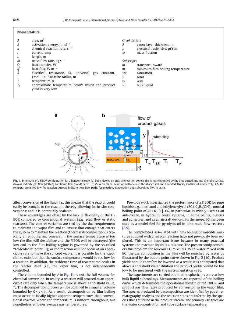
It has recently been shown that single component liquids can beconverted to lighter fractions by using the film boiling process[1–4]. The concept exploits the insulating effect of a vapor film sur-rounding a heated surface in film boiling to raise gas phase temper-atures at the solid surface to levels that can promote thermaldecomposition while maintaining the vapor film. Fig. 1a is a sche-matic of the process for the configuration of a horizontal tube.3
With film boiling, a vapor layer (of thickness d) is created on thetube surface. The comparatively low thermal conductivity of thegas results in temperatures that range from Tw at the tube surface,to Tsat at the liquid/vapor interface. This temperature differencecan be over a thousand degrees. Considering that many organic va-pors will thermally crack or decompose when exposed to suchtemperatures, the high temperatures in the vapor layer have the
ll rights reserved..030
: +1 845 938 5522.ta).
neering, United States Military
n, National Institute of Stan-
ts simplicity to develop anoncept also applies to other.
potential to drive chemical reaction in a cold bulk liquid. We havetermed the volume bounded by d a film boiling reactor or ‘‘FIBOR’’[1,5]. Its operational boundaries are governed by the boiling curveof a liquid. In the film boiling regime, the energy input to the tube(or heat generated by Joule heating) must maintain the vapor filmand support the reaction, which is typically endothermic for organ-ic vapors. Fig. 1b schematically illustrates the energy transportpaths for film boiling with chemical reaction. If the vapor film isnot maintained or the surface temperature is too low, the chemicalreaction process ceases.
The FIBOR conceptually has several unique features comparedto conventional plug flow or packed bed reactors: it essentiallybuilds itself by the natural transition of heat transfer modes whena surface is heated in a liquid pool, from single phase convection, tonucleate boiling, the critical heat flux (CHF) condition and ulti-mately film boiling; high temperature conversion occurs in a coldbulk liquid because of the insulating affect of the vapor film, whichmitigates high temperature containment issues of conventionalreactor systems [6]; the reactor design is simple as it involves nomoving parts (e.g., pumps to transport the reactant through thereactor, which for the FIBOR occurs by evaporation at the liquid/va-por interface); products are transported by bubbles under the ac-tion of buoyancy (a variant could develop the reactor in forcedconvection film boiling); the FIBOR is inherently portable as it re-quires only that a heated surface be inserted into a liquid pool to
Nomenclature
A area, m2
E activation energy, J mol�1
k chemical reaction rate, s�1
I current, ampL length, m_m mass flow rate, kg s�1
Q heat transfer, Wq’’ heat flux, W m�2
R electrical resistance, X, universal gas constant,J mol�1 K�1 or tube radius, m
T temperature, KTr approximate temperature below which the product
yield is very low
Greek Lettersd vapor layer thickness, mq electrical resistivity, lX mu mass fraction
Subscriptsin transport inwardm minimum film boiling temperaturesat saturations solidw wall1 bulk liquid
Fig. 1. Schematic of a FIBOR configuration for a horizontal tube. (a) Tube viewed on end; the reaction zone is the volume bounded by the blue dotted line and the tube surface.Arrows indicate gas flow (dotted) and liquid flow (solid) paths. (b) View on plane. Reaction will occur in the shaded volume bounded, 0<y<dr. Outside of dr where Tw < Tr, thetemperature is too low for reaction. Arrows indicate heat flow paths for reaction, evaporation and subcooling. Not to scale.
6426 J.W. Evangelista et al. / International Journal of Heat and Mass Transfer 55 (2012) 6425–6434
affect conversion of the fluid (i.e., this means that the reactor couldeasily be brought to the reactant thereby allowing for in-situ con-version); and it is potentially scalable.
These advantages are offset by the lack of flexibility of the FI-BOR compared to conventional systems (e.g., plug flow or staticreactors). The control variables are tied by the dual requirementto maintain the vapor film and to ensure that enough heat entersthe system to maintain the reaction (thermal decomposition is typ-ically an endothermic process). If the surface temperature is toolow the film will destabilize and the FIBOR will be destroyed (thelow end to the film boiling regime is governed by the so-called‘‘Leidenfrost’’ point [7]) or the reaction will not occur at an appre-ciable rate to make the concept viable; it is possible for the vaporfilm to exist but that the surface temperature would be too low fora reaction. In addition, the residence time of reactant molecules inthe reactor itself (i.e., the vapor film) is not independentlycontrolled.
The volume bounded by d in Fig. 1b is not the full volume forchemical conversion. In reality, a reaction will proceed at an appre-ciable rate only when the temperature is above a threshold value,Tr. The decomposition process will be confined to a smaller volumebounded by 0 < y < dr. As a result, decomposition by film boilingmust occur at locally higher apparent temperatures than conven-tional reactors where the temperature is uniform throughout, butnonetheless at lower average gas temperatures.
Previous work investigated the performance of a FIBOR for pureliquids (e.g., methanol and ethylene glycol (EG), C2H4(OH)2, normalboiling point of 467 K) [1]. EG, in particular, is widely used as ananti-freeze, in hydraulic brake systems, in some paints, plasticsand adhesives, and as an aircraft de-icer. Furthermore, EG has beenused as a model fuel for pyrolysis oil in pilot scale flow reactors[8,9].
The complexities associated with film boiling of miscible mix-tures coupled with chemical reaction have not previously been ex-plored. This is an important issue because in many practicalsystems the reactant liquid is a mixture. The present study consid-ers this problem for aqueous EG mixtures. With water mixed withEG, the gas composition in the film will be enriched by water asillustrated by the bubble point curve shown in Fig. 2 [10]. Productyields should therefore be lowered as a result. It is anticipated thatabove a threshold water dilution the product yields would be toolow to be measured with the instrumentation used.
The experiments are carried out at atmospheric pressure at lowbulk liquid subcoolings. Measurements are reported of the boilingcurve which determines the operational domain of the FIBOR, andproduct gas flow rates produced by conversion in the vapor film.The species produced by decomposition are identified by gas chro-matography analysis and the reaction steps are inferred by the spe-cies that are found in the product stream. The primary variables arethe water concentration and tube surface temperature.
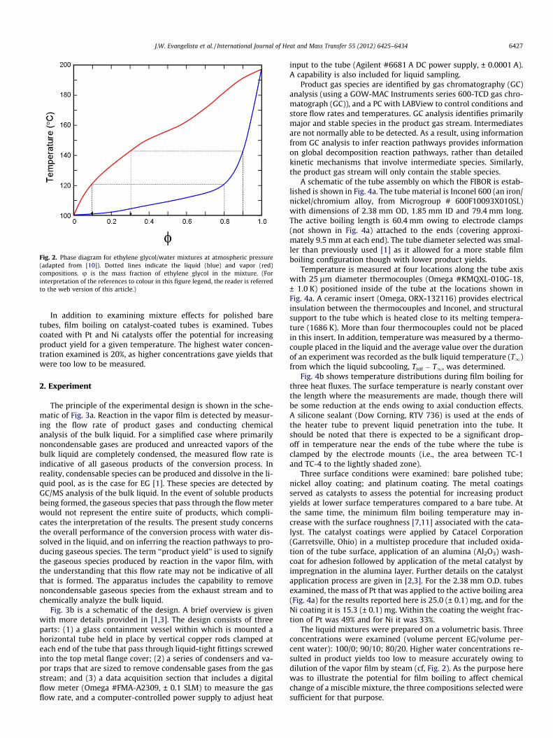
Fig. 2. Phase diagram for ethylene glycol/water mixtures at atmospheric pressure(adapted from [10]). Dotted lines indicate the liquid (blue) and vapor (red)compositions. u is the mass fraction of ethylene glycol in the mixture. (Forinterpretation of the references to colour in this figure legend, the reader is referredto the web version of this article.)
J.W. Evangelista et al. / International Journal of Heat and Mass Transfer 55 (2012) 6425–6434 6427
In addition to examining mixture effects for polished baretubes, film boiling on catalyst-coated tubes is examined. Tubescoated with Pt and Ni catalysts offer the potential for increasingproduct yield for a given temperature. The highest water concen-tration examined is 20%, as higher concentrations gave yields thatwere too low to be measured.
2. Experiment
The principle of the experimental design is shown in the sche-matic of Fig. 3a. Reaction in the vapor film is detected by measur-ing the flow rate of product gases and conducting chemicalanalysis of the bulk liquid. For a simplified case where primarilynoncondensable gases are produced and unreacted vapors of thebulk liquid are completely condensed, the measured flow rate isindicative of all gaseous products of the conversion process. Inreality, condensable species can be produced and dissolve in the li-quid pool, as is the case for EG [1]. These species are detected byGC/MS analysis of the bulk liquid. In the event of soluble productsbeing formed, the gaseous species that pass through the flow meterwould not represent the entire suite of products, which compli-cates the interpretation of the results. The present study concernsthe overall performance of the conversion process with water dis-solved in the liquid, and on inferring the reaction pathways to pro-ducing gaseous species. The term ‘‘product yield’’ is used to signifythe gaseous species produced by reaction in the vapor film, withthe understanding that this flow rate may not be indicative of allthat is formed. The apparatus includes the capability to removenoncondensable gaseous species from the exhaust stream and tochemically analyze the bulk liquid.
Fig. 3b is a schematic of the design. A brief overview is givenwith more details provided in [1,3]. The design consists of threeparts: (1) a glass containment vessel within which is mounted ahorizontal tube held in place by vertical copper rods clamped ateach end of the tube that pass through liquid-tight fittings screwedinto the top metal flange cover; (2) a series of condensers and va-por traps that are sized to remove condensable gases from the gasstream; and (3) a data acquisition section that includes a digitalflow meter (Omega #FMA-A2309, ± 0.1 SLM) to measure the gasflow rate, and a computer-controlled power supply to adjust heat
input to the tube (Agilent #6681 A DC power supply, ± 0.0001 A).A capability is also included for liquid sampling.
Product gas species are identified by gas chromatography (GC)analysis (using a GOW-MAC Instruments series 600-TCD gas chro-matograph (GC)), and a PC with LABView to control conditions andstore flow rates and temperatures. GC analysis identifies primarilymajor and stable species in the product gas stream. Intermediatesare not normally able to be detected. As a result, using informationfrom GC analysis to infer reaction pathways provides informationon global decomposition reaction pathways, rather than detailedkinetic mechanisms that involve intermediate species. Similarly,the product gas stream will only contain the stable species.
A schematic of the tube assembly on which the FIBOR is estab-lished is shown in Fig. 4a. The tube material is Inconel 600 (an iron/nickel/chromium alloy, from Microgroup # 600F10093X010SL)with dimensions of 2.38 mm OD, 1.85 mm ID and 79.4 mm long.The active boiling length is 60.4 mm owing to electrode clamps(not shown in Fig. 4a) attached to the ends (covering approxi-mately 9.5 mm at each end). The tube diameter selected was smal-ler than previously used [1] as it allowed for a more stable filmboiling configuration though with lower product yields.
Temperature is measured at four locations along the tube axiswith 25 lm diameter thermocouples (Omega #KMQXL-010G-18,± 1.0 K) positioned inside of the tube at the locations shown inFig. 4a. A ceramic insert (Omega, ORX-132116) provides electricalinsulation between the thermocouples and Inconel, and structuralsupport to the tube which is heated close to its melting tempera-ture (1686 K). More than four thermocouples could not be placedin this insert. In addition, temperature was measured by a thermo-couple placed in the liquid and the average value over the durationof an experiment was recorded as the bulk liquid temperature (T1)from which the liquid subcooling, Tsat � T1, was determined.
Fig. 4b shows temperature distributions during film boiling forthree heat fluxes. The surface temperature is nearly constant overthe length where the measurements are made, though there willbe some reduction at the ends owing to axial conduction effects.A silicone sealant (Dow Corning, RTV 736) is used at the ends ofthe heater tube to prevent liquid penetration into the tube. Itshould be noted that there is expected to be a significant drop-off in temperature near the ends of the tube where the tube isclamped by the electrode mounts (i.e., the area between TC-1and TC-4 to the lightly shaded zone).
Three surface conditions were examined: bare polished tube;nickel alloy coating; and platinum coating. The metal coatingsserved as catalysts to assess the potential for increasing productyields at lower surface temperatures compared to a bare tube. Atthe same time, the minimum film boiling temperature may in-crease with the surface roughness [7,11] associated with the cata-lyst. The catalyst coatings were applied by Catacel Corporation(Garretsville, Ohio) in a multistep procedure that included oxida-tion of the tube surface, application of an alumina (Al2O3) wash-coat for adhesion followed by application of the metal catalyst byimpregnation in the alumina layer. Further details on the catalystapplication process are given in [2,3]. For the 2.38 mm O.D. tubesexamined, the mass of Pt that was applied to the active boiling area(Fig. 4a) for the results reported here is 25.0 (± 0.1) mg, and for theNi coating it is 15.3 (± 0.1) mg. Within the coating the weight frac-tion of Pt was 49% and for Ni it was 33%.
The liquid mixtures were prepared on a volumetric basis. Threeconcentrations were examined (volume percent EG/volume per-cent water): 100/0; 90/10; 80/20. Higher water concentrations re-sulted in product yields too low to measure accurately owing todilution of the vapor film by steam (cf, Fig. 2). As the purpose herewas to illustrate the potential for film boiling to affect chemicalchange of a miscible mixture, the three compositions selected weresufficient for that purpose.
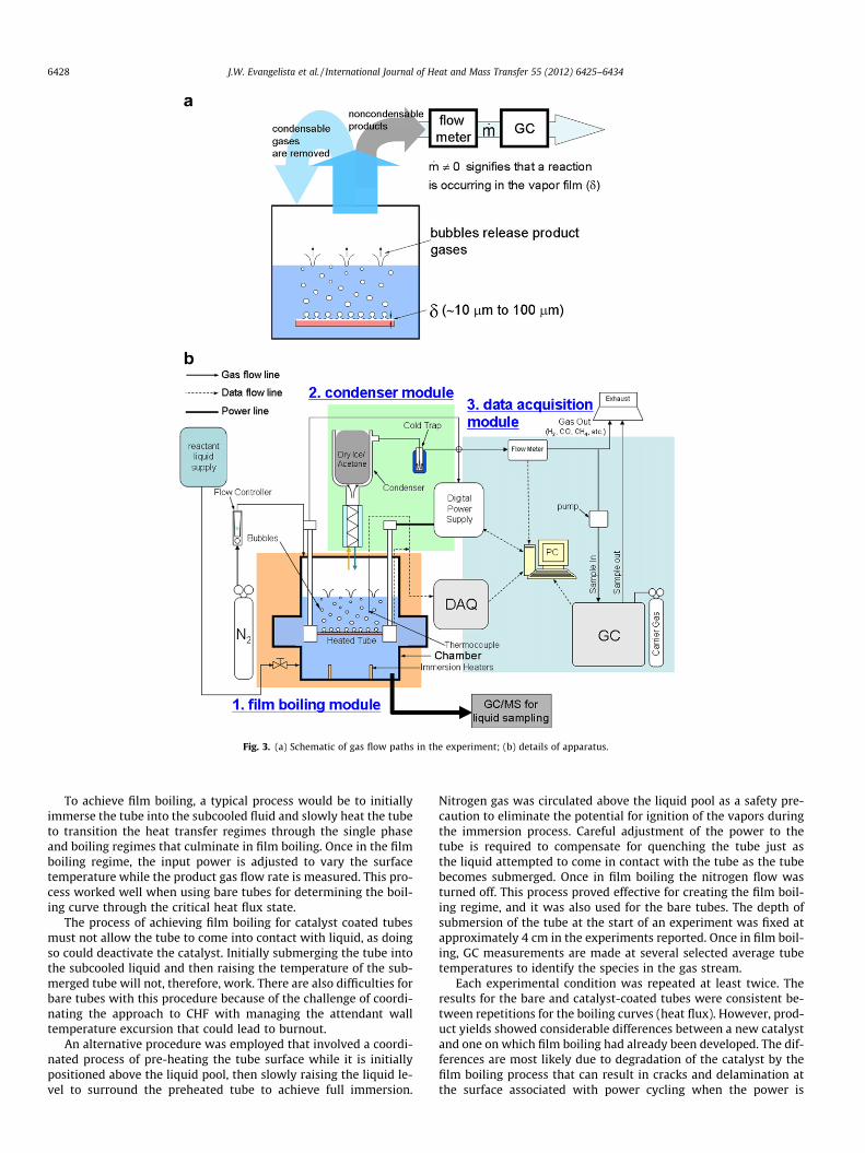
Fig. 3. (a) Schematic of gas flow paths in the experiment; (b) details of apparatus.
6428 J.W. Evangelista et al. / International Journal of Heat and Mass Transfer 55 (2012) 6425–6434
To achieve film boiling, a typical process would be to initiallyimmerse the tube into the subcooled fluid and slowly heat the tubeto transition the heat transfer regimes through the single phaseand boiling regimes that culminate in film boiling. Once in the filmboiling regime, the input power is adjusted to vary the surfacetemperature while the product gas flow rate is measured. This pro-cess worked well when using bare tubes for determining the boil-ing curve through the critical heat flux state.
The process of achieving film boiling for catalyst coated tubesmust not allow the tube to come into contact with liquid, as doingso could deactivate the catalyst. Initially submerging the tube intothe subcooled liquid and then raising the temperature of the sub-merged tube will not, therefore, work. There are also difficulties forbare tubes with this procedure because of the challenge of coordi-nating the approach to CHF with managing the attendant walltemperature excursion that could lead to burnout.
An alternative procedure was employed that involved a coordi-nated process of pre-heating the tube surface while it is initiallypositioned above the liquid pool, then slowly raising the liquid le-vel to surround the preheated tube to achieve full immersion.
Nitrogen gas was circulated above the liquid pool as a safety pre-caution to eliminate the potential for ignition of the vapors duringthe immersion process. Careful adjustment of the power to thetube is required to compensate for quenching the tube just asthe liquid attempted to come in contact with the tube as the tubebecomes submerged. Once in film boiling the nitrogen flow wasturned off. This process proved effective for creating the film boil-ing regime, and it was also used for the bare tubes. The depth ofsubmersion of the tube at the start of an experiment was fixed atapproximately 4 cm in the experiments reported. Once in film boil-ing, GC measurements are made at several selected average tubetemperatures to identify the species in the gas stream.
Each experimental condition was repeated at least twice. Theresults for the bare and catalyst-coated tubes were consistent be-tween repetitions for the boiling curves (heat flux). However, prod-uct yields showed considerable differences between a new catalystand one on which film boiling had already been developed. The dif-ferences are most likely due to degradation of the catalyst by thefilm boiling process that can result in cracks and delamination atthe surface associated with power cycling when the power is
J.W. Evangelista et al. / International Journal of Heat and Mass Transfer 55 (2012) 6425–6434 6429
terminated and the tube is allowed to cool back down to roomtemperature. More details and discussion of this effect are givenin [3]. Some results showing the morphological changes that occuron a catalyst tube subjected to film boiling are discussed in Sec-tion 3.3. In the present study, results are presented primarily forwhat amount to surfaces that had not previously been subjectedto film boiling.
In developing the variation of heat flux and product yield withaverage tube temperature, a staged power increase was employed.Each power setting was imposed for approximately two minutesbefore proceeding to a new power setting. This dwell time allowedsteady state temperatures to be reached. Within each setting theoutputs from the flow meter (Fig. 3) and current through the tubewere recorded for later processing to determine an average prod-uct yield and heat flux. The energy input to the liquid was com-puted from the measured current (I) through the tube and theelectrical resistance (R) of the tube as Q = I2R where R ¼ qðTwÞL
A andq(Tw) is the temperature-dependent electrical resistivity of thetube material. For Inconel 600, q is determined by the followingpolynomial with the wall temperature (Tw) in Kelvin [12]
qðTwÞ ¼ 0:4763þ 5:27� 10�3 Tw � 1:95� 10�5T2w þ 3:56
� 10�8 T3w � 3:23� 10�11 T4
w þ 1:35� 10�14 T5w � 1:89
� 10�18 T6w
Since the tube area is A = p D L, the heat flux q00 = q/A will be inde-pendent of L when the same length is used to compute q00 and R.
The temperature assigned to the heat flux was assumed to bethe average of the four locations shown in Fig. 4a. This average will
Fig. 4. (a) Schematic of tube assembly for film boiling showing locations of thethermocouples. The dimensions are in millimeters. Lightly shaded area of tube is incontact with electrode clamps and not exposed to reactant liquid. (b) Represen-tative variation of surface temperature with distance along the tube for thelocations in ‘‘a’’ at the three heat fluxes listed in the inset.
be different from the actual average temperature that would havebeen obtained were it possible to insert more thermocouples intothe tubes, because of the expected drop-off of temperature at theend of the tube where the electrodes are attached due to conduc-tive losses [1]. An additional consideration is the temperature dropin the radial direction, namely from the location of the thermocou-ple and the outside surface of the tube. A simple conduction model[3] was used to estimate these effects which showed that thecumulative correction would be less than 5K for the range of inputpowers examined.
3. Results
3.1. Boiling curves
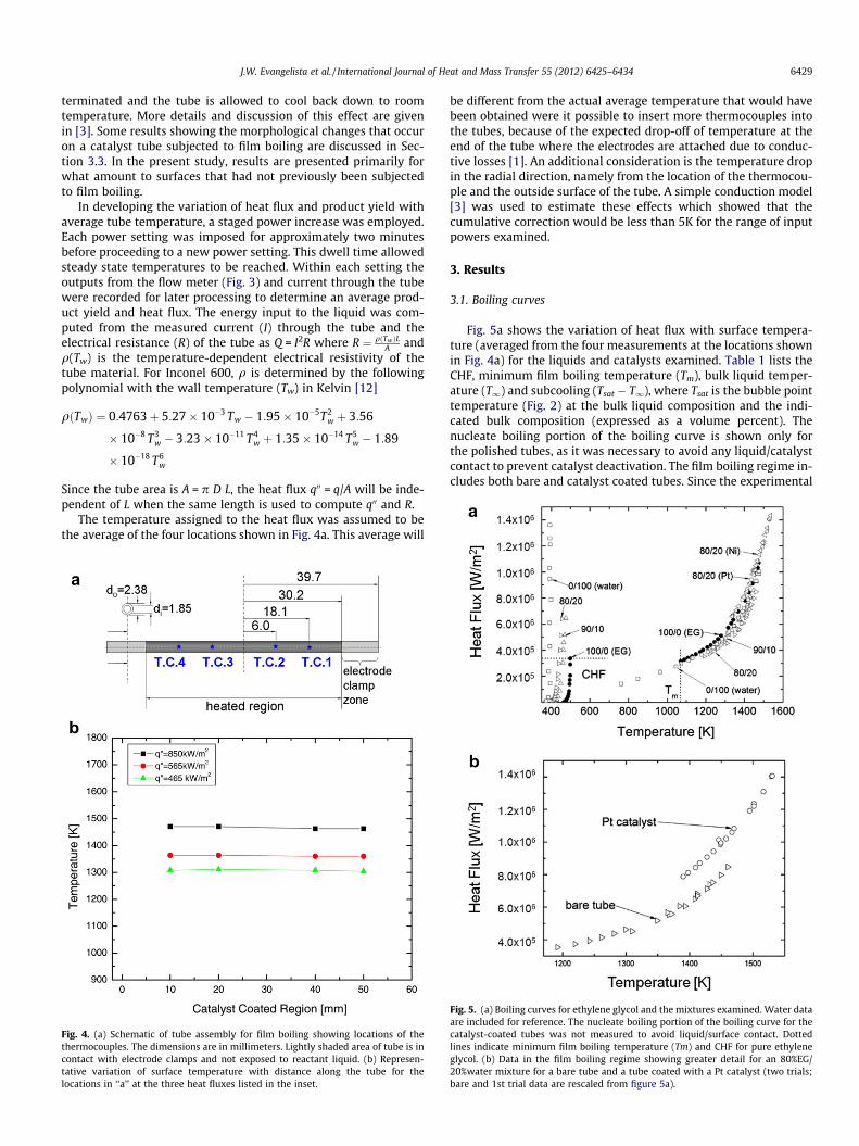
Fig. 5a shows the variation of heat flux with surface tempera-ture (averaged from the four measurements at the locations shownin Fig. 4a) for the liquids and catalysts examined. Table 1 lists theCHF, minimum film boiling temperature (Tm), bulk liquid temper-ature (T1) and subcooling (Tsat � T1), where Tsat is the bubble pointtemperature (Fig. 2) at the bulk liquid composition and the indi-cated bulk composition (expressed as a volume percent). Thenucleate boiling portion of the boiling curve is shown only forthe polished tubes, as it was necessary to avoid any liquid/catalystcontact to prevent catalyst deactivation. The film boiling regime in-cludes both bare and catalyst coated tubes. Since the experimental
Fig. 5. (a) Boiling curves for ethylene glycol and the mixtures examined. Water dataare included for reference. The nucleate boiling portion of the boiling curve for thecatalyst-coated tubes was not measured to avoid liquid/surface contact. Dottedlines indicate minimum film boiling temperature (Tm) and CHF for pure ethyleneglycol. (b) Data in the film boiling regime showing greater detail for an 80%EG/20%water mixture for a bare tube and a tube coated with a Pt catalyst (two trials;bare and 1st trial data are rescaled from figure 5a).
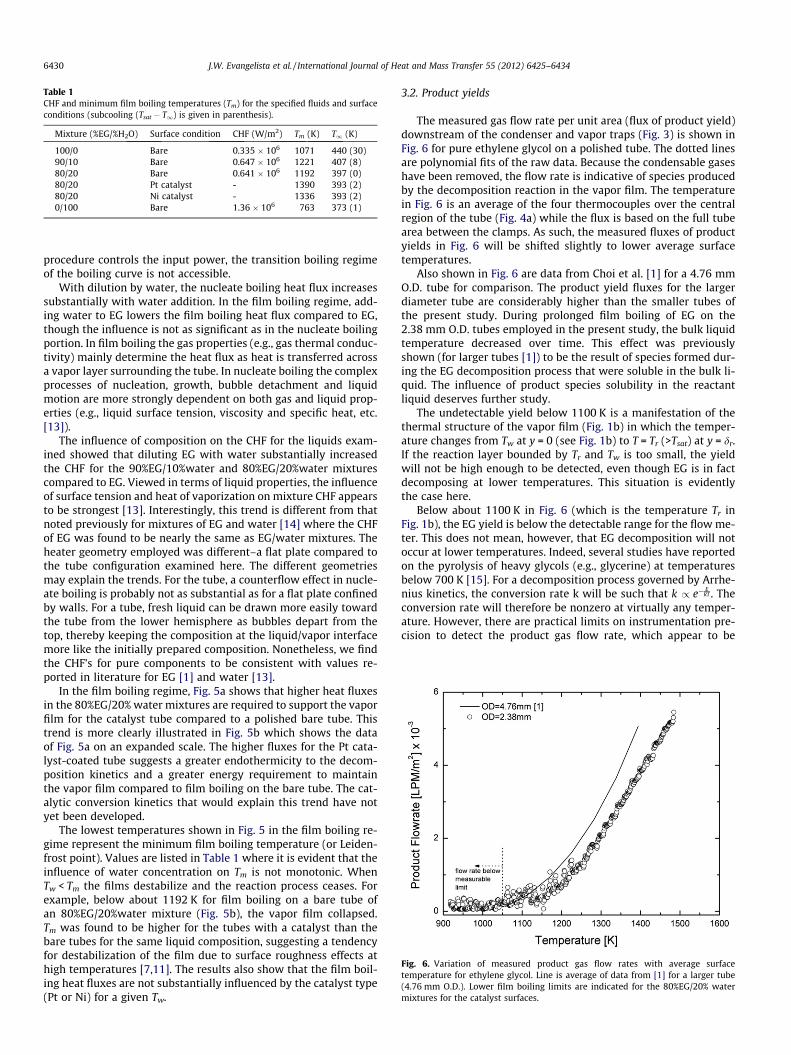
Table 1CHF and minimum film boiling temperatures (Tm) for the specified fluids and surfaceconditions (subcooling (Tsat � T1) is given in parenthesis).
Mixture (%EG/%H2O) Surface condition CHF (W/m2) Tm (K) T1 (K)
100/0 Bare 0.335 � 106 1071 440 (30)90/10 Bare 0.647 � 106 1221 407 (8)80/20 Bare 0.641 � 106 1192 397 (0)80/20 Pt catalyst - 1390 393 (2)80/20 Ni catalyst - 1336 393 (2)0/100 Bare 1.36 � 106 763 373 (1)
Fig. 6. Variation of measured product gas flow rates with average surfacetemperature for ethylene glycol. Line is average of data from [1] for a larger tube(4.76 mm O.D.). Lower film boiling limits are indicated for the 80%EG/20% watermixtures for the catalyst surfaces.
6430 J.W. Evangelista et al. / International Journal of Heat and Mass Transfer 55 (2012) 6425–6434
procedure controls the input power, the transition boiling regimeof the boiling curve is not accessible.
With dilution by water, the nucleate boiling heat flux increasessubstantially with water addition. In the film boiling regime, add-ing water to EG lowers the film boiling heat flux compared to EG,though the influence is not as significant as in the nucleate boilingportion. In film boiling the gas properties (e.g., gas thermal conduc-tivity) mainly determine the heat flux as heat is transferred acrossa vapor layer surrounding the tube. In nucleate boiling the complexprocesses of nucleation, growth, bubble detachment and liquidmotion are more strongly dependent on both gas and liquid prop-erties (e.g., liquid surface tension, viscosity and specific heat, etc.[13]).
The influence of composition on the CHF for the liquids exam-ined showed that diluting EG with water substantially increasedthe CHF for the 90%EG/10%water and 80%EG/20%water mixturescompared to EG. Viewed in terms of liquid properties, the influenceof surface tension and heat of vaporization on mixture CHF appearsto be strongest [13]. Interestingly, this trend is different from thatnoted previously for mixtures of EG and water [14] where the CHFof EG was found to be nearly the same as EG/water mixtures. Theheater geometry employed was different–a flat plate compared tothe tube configuration examined here. The different geometriesmay explain the trends. For the tube, a counterflow effect in nucle-ate boiling is probably not as substantial as for a flat plate confinedby walls. For a tube, fresh liquid can be drawn more easily towardthe tube from the lower hemisphere as bubbles depart from thetop, thereby keeping the composition at the liquid/vapor interfacemore like the initially prepared composition. Nonetheless, we findthe CHF’s for pure components to be consistent with values re-ported in literature for EG [1] and water [13].
In the film boiling regime, Fig. 5a shows that higher heat fluxesin the 80%EG/20% water mixtures are required to support the vaporfilm for the catalyst tube compared to a polished bare tube. Thistrend is more clearly illustrated in Fig. 5b which shows the dataof Fig. 5a on an expanded scale. The higher fluxes for the Pt cata-lyst-coated tube suggests a greater endothermicity to the decom-position kinetics and a greater energy requirement to maintainthe vapor film compared to film boiling on the bare tube. The cat-alytic conversion kinetics that would explain this trend have notyet been developed.
The lowest temperatures shown in Fig. 5 in the film boiling re-gime represent the minimum film boiling temperature (or Leiden-frost point). Values are listed in Table 1 where it is evident that theinfluence of water concentration on Tm is not monotonic. WhenTw < Tm the films destabilize and the reaction process ceases. Forexample, below about 1192 K for film boiling on a bare tube ofan 80%EG/20%water mixture (Fig. 5b), the vapor film collapsed.Tm was found to be higher for the tubes with a catalyst than thebare tubes for the same liquid composition, suggesting a tendencyfor destabilization of the film due to surface roughness effects athigh temperatures [7,11]. The results also show that the film boil-ing heat fluxes are not substantially influenced by the catalyst type(Pt or Ni) for a given Tw.
3.2. Product yields
The measured gas flow rate per unit area (flux of product yield)downstream of the condenser and vapor traps (Fig. 3) is shown inFig. 6 for pure ethylene glycol on a polished tube. The dotted linesare polynomial fits of the raw data. Because the condensable gaseshave been removed, the flow rate is indicative of species producedby the decomposition reaction in the vapor film. The temperaturein Fig. 6 is an average of the four thermocouples over the centralregion of the tube (Fig. 4a) while the flux is based on the full tubearea between the clamps. As such, the measured fluxes of productyields in Fig. 6 will be shifted slightly to lower average surfacetemperatures.
Also shown in Fig. 6 are data from Choi et al. [1] for a 4.76 mmO.D. tube for comparison. The product yield fluxes for the largerdiameter tube are considerably higher than the smaller tubes ofthe present study. During prolonged film boiling of EG on the2.38 mm O.D. tubes employed in the present study, the bulk liquidtemperature decreased over time. This effect was previouslyshown (for larger tubes [1]) to be the result of species formed dur-ing the EG decomposition process that were soluble in the bulk li-quid. The influence of product species solubility in the reactantliquid deserves further study.
The undetectable yield below 1100 K is a manifestation of thethermal structure of the vapor film (Fig. 1b) in which the temper-ature changes from Tw at y = 0 (see Fig. 1b) to T = Tr (>Tsat) at y = dr.If the reaction layer bounded by Tr and Tw is too small, the yieldwill not be high enough to be detected, even though EG is in factdecomposing at lower temperatures. This situation is evidentlythe case here.
Below about 1100 K in Fig. 6 (which is the temperature Tr inFig. 1b), the EG yield is below the detectable range for the flow me-ter. This does not mean, however, that EG decomposition will notoccur at lower temperatures. Indeed, several studies have reportedon the pyrolysis of heavy glycols (e.g., glycerine) at temperaturesbelow 700 K [15]. For a decomposition process governed by Arrhe-nius kinetics, the conversion rate k will be such that k / e�
ERT . The
conversion rate will therefore be nonzero at virtually any temper-ature. However, there are practical limits on instrumentation pre-cision to detect the product gas flow rate, which appear to be
J.W. Evangelista et al. / International Journal of Heat and Mass Transfer 55 (2012) 6425–6434 6431
reached at around 1100 K for the instrumentation employed in thepresent study.
The residence time of reactant molecules as they are trans-ported through the high temperature zone of the vapor film (e.g.,by buoyancy in the vapor film or by a carrier gas in a packed bedreactor) determines the reactant decomposition rate. Conventionalreactor designs (e.g., the tubular or packed bed reactor) achievehigh yields at low temperatures by promoting long residence times(order of seconds or larger). By contrast, for pool film boiling of ahorizontal tube in a gravitational field the residence time is not acontrol variable but is instead determined by the mechanism thatmoves gases in the vapor film around the tube, which for the pres-ent study is buoyancy. Residence times on the order of tens of mil-liseconds are estimated for this situation [5]. To compensate,higher average gas temperatures are necessary for conversion byfilm boiling to occur at measurable rates within the film. Alterna-tive surface geometries and orientations that would seek to in-crease the residence time for supporting film boiling couldalleviate this concern.
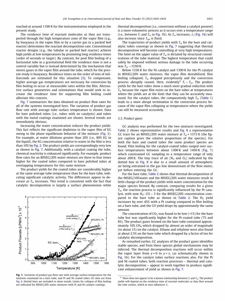
Fig. 7 summarizes the data obtained on product flow rates forall of the systems investigated here. The variation of product gasflow rate with average tube surface temperature is shown. Datafor bare polished tubes (i.e., tubes with no catalysts) and tubeswith the metal coatings examined are shown. Several trends areimmediately obvious.
Increasing the water concentration reduces the product yields.This fact reflects the significant depletion in the vapor film of EGowing to the phase equilibrium behavior of the mixture (Fig. 2).For example, at water dilutions greater than 20% (i.e., 80% EG inthe liquid), the EG concentration relative to water in the film is lessthan 10% by Fig. 2. The product yields are correspondingly very lowas shown in Fig. 7. Additionally, with a catalyst coating the tube,chemical reactivity is enhanced significantly. For example, productflow rates for an 80%EG/20% water mixture are three to four timeshigher for the coated tubes compared to bare polished tubes atoverlapping temperatures for this same mixture.
The product yields for the coated tubes are considerably higherat the same average tube temperature than for the bare tube, indi-cating significant catalytic activity. The differences appear to de-crease as Tw increases. This trend is consistent with the fact thatcatalytic decomposition is largely a surface phenomenon while
Fig. 7. Variation of product gas flow rate with average surface temperature for themixtures examined on a bare tube, and Pt and Ni coated tubes. EG data are fromFig. 6. Dotted lines are included to show trends. Limits for collapse of film boilingare indicated for 80%EG/20% water mixtures with Pt and Ni catalyst coatings.
thermal decomposition (i.e., conversion without a catalyst present)is a more volumetric process as it occurs over a temperature range(i.e., between Tr and Tw in Fig. 1b). As Tw increases, dr (Fig. 1b) willalso increase since Tsat is fixed.
The trajectories of product yields with Tw for the bare and cat-alytic tubes converge as shown in Fig. 7 suggesting that thermaldecomposition will become controlling at very high temperatures.The limit on the upper value of Tw is dictated by structural consid-erations of the tube material. The highest temperature that couldsafely be imposed without serious damage to the tube occurringwas Tw �1550 K.
Below 1336 K for the Ni catalyst and 1390 K for the Pt catalystin 80%EG/20% water mixtures, the vapor film destabilized, filmboiling collapsed, Tw dropped precipitously and the conversionprocess abruptly ceased. Here, evidently4 Tr � Tm. The productyields for the bare tubes show a much more gradual reduction withTw because the vapor film exists on the bare tubes at temperatureswhere the yields are at the limit that they can be accurately mea-sured. For the catalyst tubes, the comparatively high Tm (Table 1)leads to a more abrupt termination in the conversion process be-cause of the vapor film collapsing at temperatures where the yieldscan still be measured accurately.
3.3. Product gases
GC analysis was performed for the two mixtures investigated.Table 2 shows representative results and Fig. 8 a representativeGC trace for an 80%EG/20% water mixture at Tw = 1373 K (the fig-ure caption gives the relative proportions of the species). Forboth the bare and coated tubes the same product species arefound. Film boiling for the catalyst-coated tubes ranged over sur-face temperatures between about 1300 K and 1450 K (Fig. 7)which constrained GC sampling to a temperature range of onlyabout 200 K. The tiny trace of air (N2 and O2) indicated by thedotted box in Fig. 8 is due to a small amount of atmosphericair being entrained in the gas line downstream of the flow meter,yet before entering the GC.
For the bare tube, Table 2 shows that thermal decomposition ofthe 90%EG/10%water and the 80%EG/20% water mixtures result inlittle change of the product yields with water concentration for themajor species formed. By contrast, comparing results for a givenTw, the reaction process is significantly influenced by the Pt cata-lyst, with now H2: CO � 3 for the 80%EG/20% concentration com-pared to the bare tube as shown in Table 2. The H2 yieldincreases by over 45% with a Pt coating compared to film boilingon a bare tube, and the CO yield drops by approximately the sameamount.
The concentration of CO2 was found to be low (<1%) for the baretube but was significantly higher for the Pt-coated tube (7% and8%). The product gases formed on the bare tube contained approx-imately 10% CH4 which dropped by almost an order of magnitude(to about 1%) on the catalyst. Ethane and ethylene were also foundat about 2.5% on the bare tube which dropped by a factor of ten forcatalytic decomposition.
As remarked earlier, GC analyses of the product gases identifiesstable species, and from these species global mechanisms may beinferred. The thermal decomposition reactions will occur withinthe vapor layer from y = 0 to y = dr (as schematically shown inFig. 1b). For the catalyst tubes surface reactions also. For the Ptand Ni coated tubes, both reaction processes – thermal and cata-lytic decomposition – appear to work together to produce signifi-cant enhancement of yield as shown in Fig. 7.
4 There does not appear to be a known relationship between Tr and Tm. The productyields will depend on the residence time of reactant molecules as they flow aroundthe tube surface, which in turn influences Tr.
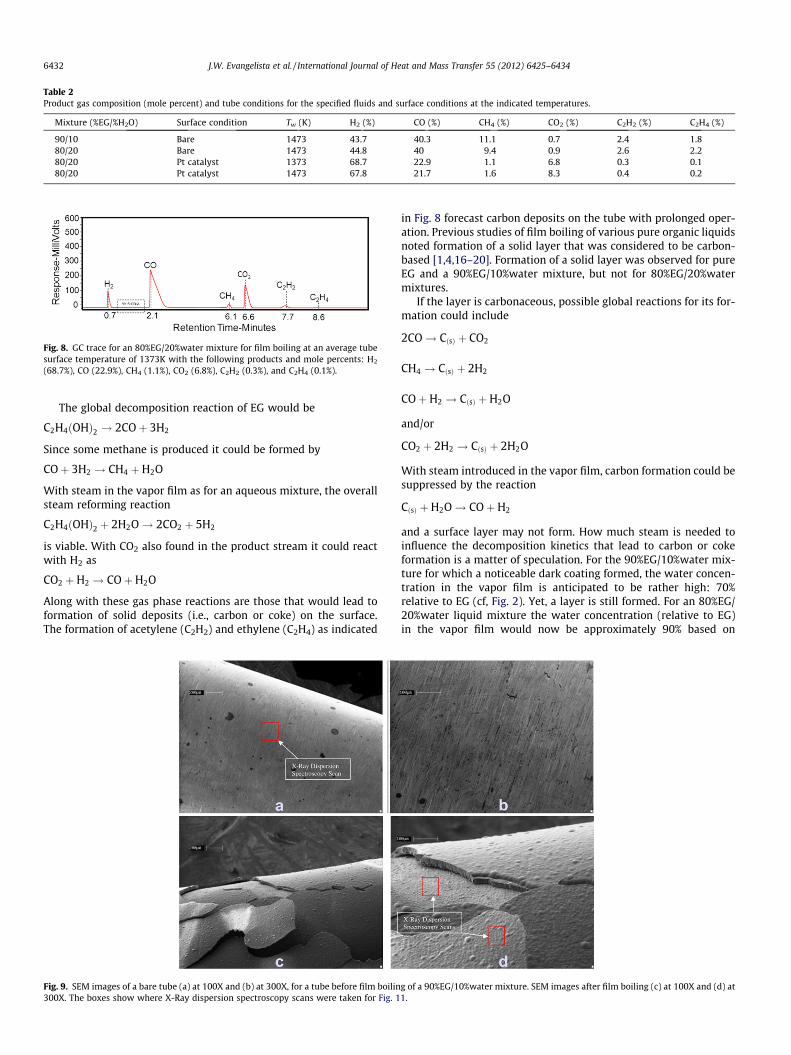
Table 2Product gas composition (mole percent) and tube conditions for the specified fluids and surface conditions at the indicated temperatures.
Mixture (%EG/%H2O) Surface condition Tw (K) H2 (%) CO (%) CH4 (%) CO2 (%) C2H2 (%) C2H4 (%)
90/10 Bare 1473 43.7 40.3 11.1 0.7 2.4 1.880/20 Bare 1473 44.8 40 9.4 0.9 2.6 2.280/20 Pt catalyst 1373 68.7 22.9 1.1 6.8 0.3 0.180/20 Pt catalyst 1473 67.8 21.7 1.6 8.3 0.4 0.2
Fig. 8. GC trace for an 80%EG/20%water mixture for film boiling at an average tubesurface temperature of 1373K with the following products and mole percents: H2
(68.7%), CO (22.9%), CH4 (1.1%), CO2 (6.8%), C2H2 (0.3%), and C2H4 (0.1%).
6432 J.W. Evangelista et al. / International Journal of Heat and Mass Transfer 55 (2012) 6425–6434
The global decomposition reaction of EG would be
C2H4ðOHÞ2 ! 2COþ 3H2
Since some methane is produced it could be formed by
COþ 3H2 ! CH4 þH2O
With steam in the vapor film as for an aqueous mixture, the overallsteam reforming reaction
C2H4ðOHÞ2 þ 2H2O! 2CO2 þ 5H2
is viable. With CO2 also found in the product stream it could reactwith H2 as
CO2 þH2 ! COþH2O
Along with these gas phase reactions are those that would lead toformation of solid deposits (i.e., carbon or coke) on the surface.The formation of acetylene (C2H2) and ethylene (C2H4) as indicated
Fig. 9. SEM images of a bare tube (a) at 100X and (b) at 300X, for a tube before film boilin300X. The boxes show where X-Ray dispersion spectroscopy scans were taken for Fig. 1
in Fig. 8 forecast carbon deposits on the tube with prolonged oper-ation. Previous studies of film boiling of various pure organic liquidsnoted formation of a solid layer that was considered to be carbon-based [1,4,16–20]. Formation of a solid layer was observed for pureEG and a 90%EG/10%water mixture, but not for 80%EG/20%watermixtures.
If the layer is carbonaceous, possible global reactions for its for-mation could include
2CO! CðsÞ þ CO2
CH4 ! CðsÞ þ 2H2
COþH2 ! CðsÞ þH2O
and/or
CO2 þ 2H2 ! CðsÞ þ 2H2O
With steam introduced in the vapor film, carbon formation could besuppressed by the reaction
CðsÞ þH2O! COþH2
and a surface layer may not form. How much steam is needed toinfluence the decomposition kinetics that lead to carbon or cokeformation is a matter of speculation. For the 90%EG/10%water mix-ture for which a noticeable dark coating formed, the water concen-tration in the vapor film is anticipated to be rather high: 70%relative to EG (cf, Fig. 2). Yet, a layer is still formed. For an 80%EG/20%water liquid mixture the water concentration (relative to EG)in the vapor film would now be approximately 90% based on
g of a 90%EG/10%water mixture. SEM images after film boiling (c) at 100X and (d) at1.
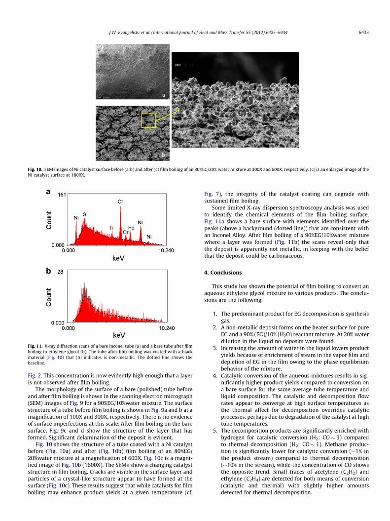
Fig. 10. SEM images of Ni catalyst surface before (a,b) and after (c) film boiling of an 80%EG/20% water mixture at 300X and 600X, respectively. (c) is an enlarged image of theNi catalyst surface at 1800X.
Fig. 11. X-ray diffraction scans of a bare Inconel tube (a) and a bare tube after filmboiling in ethylene glycol (b). The tube after film boiling was coated with a blackmaterial (Fig. 10) that (b) indicates is non-metallic. The dotted line shows thebaseline.
J.W. Evangelista et al. / International Journal of Heat and Mass Transfer 55 (2012) 6425–6434 6433
Fig. 2. This concentration is now evidently high enough that a layeris not observed after film boiling.
The morphology of the surface of a bare (polished) tube beforeand after film boiling is shown in the scanning electron micrograph(SEM) images of Fig. 9 for a 90%EG/10%water mixture. The surfacestructure of a tube before film boiling is shown in Fig. 9a and b at amagnification of 100X and 300X, respectively. There is no evidenceof surface imperfections at this scale. After film boiling on the baresurface, Fig. 9c and d show the structure of the layer that hasformed. Significant delamination of the deposit is evident.
Fig. 10 shows the structure of a tube coated with a Ni catalystbefore (Fig. 10a) and after (Fig. 10b) film boiling of an 80%EG/20%water mixture at a magnification of 600X. Fig. 10c is a magni-fied image of Fig. 10b (1600X). The SEMs show a changing catalyststructure in film boiling. Cracks are visible in the surface layer andparticles of a crystal-like structure appear to have formed at thesurface (Fig. 10c). These results suggest that while catalysts for filmboiling may enhance product yields at a given temperature (cf,
Fig. 7), the integrity of the catalyst coating can degrade withsustained film boiling.
Some limited X-ray dispersion spectroscopy analysis was usedto identify the chemical elements of the film boiling surface.Fig. 11a shows a bare surface with elements identified over thepeaks (above a background (dotted line)) that are consistent withan Inconel Alloy. After film boiling of a 90%EG/10%water mixturewhere a layer was formed (Fig. 11b) the scans reveal only thatthe deposit is apparently not metallic, in keeping with the beliefthat the deposit could be carbonaceous.
4. Conclusions
This study has shown the potential of film boiling to convert anaqueous ethylene glycol mixture to various products. The conclu-sions are the following.
1. The predominant product for EG decomposition is synthesisgas.
2. A non-metallic deposit forms on the heater surface for pureEG and a 90% (EG)/10% (H2O) reactant mixture. At 20% waterdilution in the liquid no deposits were found.
3. Increasing the amount of water in the liquid lowers productyields because of enrichment of steam in the vapor film anddepletion of EG in the film owing to the phase equilibriumbehavior of the mixture.
4. Catalytic conversion of the aqueous mixtures results in sig-nificantly higher product yields compared to conversion ona bare surface for the same average tube temperature andliquid composition. The catalytic and decomposition flowrates appear to converge at high surface temperatures asthe thermal affect for decomposition overrides catalyticprocesses, perhaps due to degradation of the catalyst at hightube temperatures.
5. The decomposition products are significantly enriched withhydrogen for catalytic conversion (H2: CO � 3) comparedto thermal decomposition (H2: CO � 1). Methane produc-tion is significantly lower for catalytic conversion (�1% inthe product stream) compared to thermal decomposition(�10% in the stream), while the concentration of CO showsthe opposite trend. Small traces of acetylene (C2H2) andethylene (C2H4) are detected for both means of conversion(catalytic and thermal) with slightly higher amountsdetected for thermal decomposition.

6434 J.W. Evangelista et al. / International Journal of Heat and Mass Transfer 55 (2012) 6425–6434
6. Platinum exhibits slightly better performance than nickel asa catalyst in terms of overall product yield and resistance todeactivation. Nickel, however, will be more attractive at lar-ger scales due to its comparatively lower cost.
7. The minimum film boiling temperature was close to thetube temperature limit where decomposition could just bedetected. The coated tubes had significantly higher Leiden-frost temperatures than the bare tubes.
Acknowledgements
This research was supported by NSF grant no. CTS-0933521. Theauthors appreciate the useful insights and help offered by Dr. SungChoi on the experimental design and procedures. Dr. William B.Retallic of Catacel Corporation is thanked for his assistance withfabricating the catalyst coatings.
References
[1] .S.R. Choi, J.W. Evangelista, C.T. Avedisian, W. Tsang, Experimental study ofchemical conversion of methanol and ethylene glycol in a film boiling reactor,Int. J. Heat Mass Transfer 54 (2011) 500–511.
[2] S.R. Choi, Experimental study of chemical conversion of organic liquids by filmboiling, Ph.D Thesis, Cornell University, 2010.
[3] J.W. Evangelista, An experimental demonstration of converting organic liquidsand their aqueous solutions in a film boiling reactor, M.S. Thesis, CornellUniversity, 2010.
[4] S.A. Zhukov, V.A. Rafeev, S. Yu, S.B. Afans’ev, S.B. Echmaev, B.L. Korsunksii,Singularities of realization of film boiling on wire heaters, High Temp. 41(2003) 243–251.
[5] B.J. Urban, C.T. Avedisian, W. Tsang, The film boiling reactor: a newenvironment for chemical processing, AIChE J. 52 (2006) 2582–2595.
[6] P.N. Kechagiopoulos, S.S. Voutetakis, A.A. Lemonidou, I.A. Vasalos, Sustainablehydrogen production via reforming of ethylene glycol using a novel spoutedbed reactor, Catal. Today 127 (2007) 246–255.
[7] J.D. Bernardin, I. Mudawar, The leidenfrost point: experimental study andassessment of existing models, ASME J. Heat Transfer 121 (1999) 894–903.
[8] S. Hafner, A. Rashidi, G. Baldea, U. Riedel, A detailed chemical kinetic model ofhigh-temperature ethylene glycol gasification, Comb. Theor. Model. 15 (2011)517–535.
[9] V.A. Maroni, S.J. Epperson, An in situ infrared spectroscopic investigation of thepyrolysis of ethylene glycol encapsulated in silica sodalite, Vib. Spectrosc. 27(2001) 43–51.
[10] MEGlobal Group, Ethylene Glycol Product Guide, (2008). (see <http://www.meglobal.biz/literature/product_guides/MEGlobal_MEG.pdf>).
[11] C.T. Avedisian, J. Koplik, Leidenfrost boiling of methanol droplets on hot porousceramic surfaces, Int. J. Heat Mass Transfer 30 (2) (1987) 279–293.
[12] Special Metals Corp. 2008 Inconel Alloy 600. Publication Number SMC-027.(<http://www.specialmetals.com/documents/Inconel%20alloy%20600%20(Sept%202008).pdf>).
[13] J.H. Lienhard IV, J.H. Lienhard V, A Heat Transfer Textbook, third ed., PhlogistonPress, Cambridge, MA, 2003. pp. 468–479.
[14] R. McGillis, V.P. Carey, On the role of marangoni effects on the critical heat fluxfor pool boiling of binary mixtures, ASME J. Heat Transfer 118 (1996) 103–109.
[15] T. Valliyappan, N.N. Bakhshi, A.K. Dalai, Pyrolysis of glycerol for the productionof hydrogen or syngas, Bioresourse Technol. 99 (2008) 4476–4483.
[16] E. Bruneton, B. Narch, B.A. Oberlin, Carbon–carbon composites prepared by arapid densification process II: Structural and textural characterizations,Carbon 35 (1997) 1593.
[17] H. Okuno, H.M. Trinquecoste, A. Derre, M. Monthioux, P. Delhaes, Catalyticeffects on carbon/carbon composites fabricated by a film boiling chemicalvapor infiltration process, J. Mater. Res. 17 (2002) 1904–1913.
[18] D. Rouvillain, M. Trinquecoste, E. Bruneton, A. Derre, P. David, P. Delhaes, Filmboiling chemical vapor infiltration: an experimental study on carbon/carboncomposite materials, Carbon 39 (2001) 1355–1365.
[19] Y. Zhang, M.N. Gamo, K. Nakagawa, T. Ando, Synthesis of aligned carbonnanotubes in organic liquids, J. Mater. Res. 17 (2002) 2457–2464.
[20] Y.F. Zhang, M.N. Gamo, C.Y. Xiao, T. Ando, Liquid phase synthesis of carbonnanotubes, Physica B 323 (2002) 293–295.