Embed Size (px)
Citation preview
International Journal of Heat and Mass Transfer 82 (2015) 250–258
Contents lists available at ScienceDirect
International Journal of Heat and Mass Transfer
journal homepage: www.elsevier .com/locate / i jhmt
Anisotropic thermal transport in MOF-5 composites
http://dx.doi.org/10.1016/j.ijheatmasstransfer.2014.11.0530017-9310/� 2014 Elsevier Ltd. All rights reserved.
⇑ Corresponding author.E-mail address: [email protected] (D.J. Siegel).
Yang Ming a, Hang Chi a, Rachel Blaser c, Chunchuan Xu c, Jun Yang c, Mike Veenstra c, Manuela Gaab d,Ulrich Müller d, Ctirad Uher a, Donald J. Siegel b,⇑a Department of Physics, University of Michigan, 1440 Randall Lab, 450 Church St., Ann Arbor, MI 48109-1040, USAb Mechanical Engineering Department, University of Michigan, 2250 G. G. Brown Laboratory, 2350 Hayward St., Ann Arbor, MI 48109-2125, USAc Ford Motor Company, Research and Advanced Engineering, MD 1170/RIC, P.O. Box 2053, Dearborn, MI 48121, USAd BASF SE, Process Research and Chemical Engineering, 67056 Ludwigshafen, Germany
a r t i c l e i n f o
Article history:Received 7 June 2014Received in revised form 17 October 2014Accepted 13 November 2014
Keywords:Metal-organic frameworksAnisotropic transportThermal conductivityHydrogen storageMicrostructure-sensitive processing
a b s t r a c t
Metal-organic frameworks (MOFs) are a new class of porous, crystalline materials with applications inthe capture, storage, and separation of gasses. Although much effort has been devoted to understandingthe properties of MOFs in powder form, in a realistic system the MOF media will likely be employed asdense compacts, such as pucks or pellets, to maximize volumetric efficiency. In these applications effi-cient transport of the heat of adsorption/desorption is an important design consideration. Consequently,densified composites consisting of a physical mixture of a MOF and expanded natural graphite (ENG)have been proposed as a means to enhance the intrinsically low thermal conductivity of these materials.Here we demonstrate that the high-aspect ratio of ENG particles, combined with uni-axial compression,results in anisotropic microstructural and thermal transport properties in composite MOF-5/ENG pellets.Microscopy of pellet cross-sections revealed a textured microstructure with MOF particle boundaries andENG orientations aligned perpendicular to the pressing direction. This anisotropy is manifested in thethermal conductivity, which is two to four times higher in directions perpendicular to the pressingdirection. We further demonstrate that this anisotropy can be exploited using two processing techniques.First, a custom die and densification process allows for reorientation of the preferred heat flow pathway.Second, a layered MOF-5/ENG microstructure increases the thermal conductivity by an order of magni-tude, with only minor ENG additions (5 wt.%). These results reveal that anisotropic thermal transportin MOF composites can be tailored using a judicious combination of second phase additions and process-ing techniques.
� 2014 Elsevier Ltd. All rights reserved.
1. Introduction
Metal-organic frameworks (MOFs) are porous, crystallinematerials comprised of metal–oxygen clusters connected by organiclinkers [1]. The high surface area, building-block-like synthesisprocedure, and permanent porosity of MOFs make them attractivecandidates for applications such as gas storage, gas separations,and catalysis [2–4]. For example, MOFs have demonstratedrecord-setting storage capacities for alternative transportation fuelssuch as hydrogen [5] and natural gas [6], and are also being exploredfor carbon capture applications [7].
While MOF attributes such as surface area and pore volumeplay an important role in determining their gas storage capacity,thermal transport properties should also be considered. For
example, in gas storage applications requiring rapid uptake (e.g.,refueling of a vehicle), the exothermic heat of adsorption [8,9]should be expelled in an efficient fashion in order to maximize per-formance. As higher temperatures reduce storage capacity, theinclusion of a heat-exchanging manifold within the storage vesselhas been explored to enhance heat removal [10]. For adsorbentshaving low thermal conductivities the demands placed upon heatexchanger increase, typically at the expense of reduced volumetricand gravimetric storage density (due to additional mass andvolume associated with the heat-exchanging manifold), and poten-tially higher cost. An alternative to an elaborate heat exchanger isto increase the thermal conductivity of the adsorbent mediumitself.
Unfortunately, the thermal transport behavior of MOFs hasreceived relatively little attention [9,11–15]. Huang et al. predictedthe thermal conductivity of single crystal MOF-5 to be 0.31 W/m Kat 300 K using molecular dynamics simulations [11]. Experimentalmeasurements on single crystals of the same MOF were also
Y. Ming et al. / International Journal of Heat and Mass Transfer 82 (2015) 250–258 251
reported over a temperature range of 6 to 300 K, with a value0.32 W/m K measured at 300 K [12]. In addition to these singlecrystal studies, Liu et al. [13] reported that the thermal conductiv-ity of MOF-5 powders could be increased via compression/pelleti-zation and through combination with high-conductivity additivessuch as expanded natural graphite (ENG), which has a thermal con-ductivity of �150 W/m K [16]. For example, in pellets densified to0.5 g/cm3 the addition of 10 wt.% ENG resulted in a factor of fiveimprovement in thermal conductivity (0.56 W/m K at 298 K)relative to neat MOF-5 pellets at the same density (0.10 W/m K).Compaction alone also improves thermal conductivity, but to asmaller extent: neat MOF-5 pellets densified from 0.3 to 0.7 g/cm3 exhibit a doubling of conductivity from 0.07 to 0.14 W/m K.
These and other studies have shown that variations in processingand composition can significantly alter materials properties [17,18].For example, uni-axial compression has been linked to the forma-tion of microstructural anisotropy in compacted ENG [19]. Similarly,the addition of high-aspect-ratio particles to a matrix phase can leadto anisotropic behavior [20] [21]. These observations suggest thatMOF/ENG pellets could also exhibit anisotropic thermal transportarising from a combination of uni-axial compression and worm-likeENG additions.
The existence of anisotropic thermal transport could impact thedesign and operation of an adsorbent-based gas storage vessel. Forexample, consider a storage system that employs a stack of densi-fied MOF ‘‘pucks.’’ The heat-exchanging manifold for this designcould consist of circular plates sandwiched between puck faces. Inthis case it is desirable to maximize transfer along the axial direc-tion of the pucks to/from the heat exchanging plates. Alternatively,for a cylindrical shell heat exchanger in contact with the rims of thepucks, facile transport along the radial direction of the pucks isdesirable. These scenarios demonstrate that quantifying (and con-trolling) the degree of thermal anisotropy is an important consider-ation when processing the storage media. Nevertheless, one shouldrecognize that densification and ENG additions generally reduce thegravimetric capacity of the storage medium [9,13–15]. Thereforethe tradeoff between improved thermal transport and lower capac-ity should be carefully considered.
The present study examines the possibility for anisotropic ther-mal transport in uni-axially compressed MOF/ENG compositesusing thermal conductivity measurements and microstructuralcharacterization on the prototype compound, MOF-5. Due to itshigh gas storage capacity and simple crystal structure, MOF-5 isperhaps the most widely studied MOF. It is comprised of 1,4-benzenedicarboxylate (BDC) organic linkers and Zn4O tetrahedralclusters, the latter serving as secondary building units. MOF-5 canadsorb a large amount of hydrogen, up to 7.1 excess wt.% at 77 Kand 40 bar [22]; recent studies have also suggested promisingperformance for natural gas storage [23]. In addition to its highgravimetric capacity, recent analysis by Goldsmith, et al. indicatedthat MOF-5 is one of a small number of MOFs that also exhibits highvolumetric gas storage densities [24].
In the present study we demonstrate that the high-aspect ratiomorphology of second-phase ENG additions, combined withuni-axial compression, results in anisotropic microstructural andthermal transport properties in composite MOF-5/ENG particles.Microscopy of pellet cross-sections confirms the presence of atextured microstructure having MOF particle boundaries and ENGorientations perpendicular to the pressing direction. Thermal con-ductivity data spanning from cryogenic to ambient temperaturesreveal that the values perpendicular to the pressing direction are2 to 4 times higher than in the pressing direction. We furthermoredemonstrate that this anisotropy can be exploited using twostraightforward processing techniques. First, a custom die/compression geometry allows for reorientation of the preferred heatflow path. Secondly, fabrication of a layered microstructure with
alternating MOF-5 and ENG layers results in an order of magnitudeincrease in thermal conductivity, at the expense of only minor ENGadditions (5 wt.%). These data suggest that the magnitude andpreferred direction for thermal transport in MOF compacts may betuned by altering the processing conditions and nature of thesecond-phase additions.
2. Experimental procedure
2.1. Materials preparation
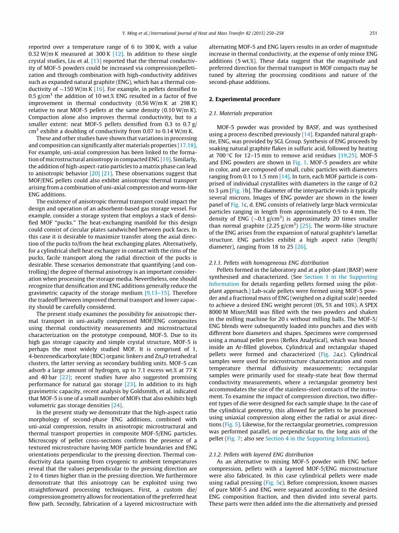
MOF-5 powder was provided by BASF, and was synthesisedusing a process described previously [14]. Expanded natural graph-ite, ENG, was provided by SGL Group. Synthesis of ENG proceeds bysoaking natural graphite flakes in sulfuric acid, followed by heatingat 700 �C for 12–15 min to remove acid residues [19,25]. MOF-5and ENG powders are shown in Fig. 1. MOF-5 powders are whitein color, and are composed of small, cubic particles with diametersranging from 0.1 to 1.5 mm [14]. In turn, each MOF particle is com-prised of individual crystallites with diameters in the range of 0.2to 3 lm [Fig. 1b]. The diameter of the interparticle voids is typicallyseveral microns. Images of ENG powder are shown in the lowerpanel of Fig. 1c, d. ENG consists of relatively large black vermicularparticles ranging in length from approximately 0.5 to 4 mm. Thedensity of ENG (�0.1 g/cm3) is approximately 20 times smallerthan normal graphite (2.25 g/cm3) [25]. The worm-like structureof the ENG arises from the expansion of natural graphite’s lamellarstructure. ENG particles exhibit a high aspect ratio (length/diameter), ranging from 18 to 25 [26].
2.1.1. Pellets with homogeneous ENG distributionPellets formed in the laboratory and at a pilot-plant (BASF) were
synthesised and characterized. (See Section 1 in the SupportingInformation for details regarding pellets formed using the pilot-plant approach.) Lab-scale pellets were formed using MOF-5 pow-der and a fractional mass of ENG (weighed on a digital scale) neededto achieve a desired ENG weight percent (0%, 5% and 10%). A SPEX8000 M Mixer/Mill was filled with the two powders and shakenin the milling machine for 20 s without milling balls. The MOF-5/ENG blends were subsequently loaded into punches and dies withdifferent bore diameters and shapes. Specimens were compressedusing a manual pellet press (Reflex Analytical), which was housedinside an Ar-filled glovebox. Cylindrical and rectangular shapedpellets were formed and characterized (Fig. 2a,c). Cylindricalsamples were used for microstructure characterization and roomtemperature thermal diffusivity measurements; rectangularsamples were primarily used for steady-state heat flow thermalconductivity measurements, where a rectangular geometry bestaccommodates the size of the stainless-steel contacts of the instru-ment. To examine the impact of compression direction, two differ-ent types of die were designed for each sample shape. In the case ofthe cylindrical geometry, this allowed for pellets to be processedusing uniaxial compression along either the radial or axial direc-tions (Fig. 5). Likewise, for the rectangular geometries, compressionwas performed parallel, or perpendicular to, the long axis of thepellet (Fig. 7; also see Section 4 in the Supporting Information).
2.1.2. Pellets with layered ENG distributionAs an alternative to mixing MOF-5 powder with ENG before
compression, pellets with a layered MOF-5/ENG microstructurewere also fabricated. In this case cylindrical pellets were madeusing radial pressing (Fig. 5c). Before compression, known massesof pure MOF-5 and ENG were separated according to the desiredENG composition fraction, and then divided into several parts.These parts were then added into the die alternatively and pressed
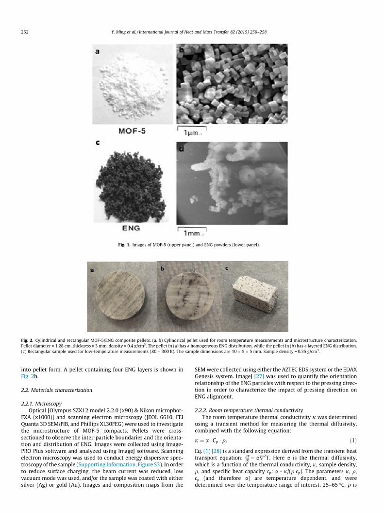
Fig. 1. Images of MOF-5 (upper panel) and ENG powders (lower panel).
Fig. 2. Cylindrical and rectangular MOF-5/ENG composite pellets. (a, b) Cylindrical pellet used for room temperature measurements and microstructure characterization.Pellet diameter = 1.28 cm, thickness = 3 mm, density = 0.4 g/cm3. The pellet in (a) has a homogeneous ENG distribution, while the pellet in (b) has a layered ENG distribution.(c) Rectangular sample used for low-temperature measurements (80 – 300 K). The sample dimensions are 10 � 5 � 5 mm. Sample density = 0.35 g/cm3.
252 Y. Ming et al. / International Journal of Heat and Mass Transfer 82 (2015) 250–258
into pellet form. A pellet containing four ENG layers is shown inFig. 2b.
2.2. Materials characterization
2.2.1. MicroscopyOptical [Olympus SZX12 model 2.2.0 (x90) & Nikon microphot-
FXA (x1000)] and scanning electron microscopy (JEOL 6610, FEIQuanta 3D SEM/FIB, and Phillips XL30FEG) were used to investigatethe microstructure of MOF-5 compacts. Pellets were cross-sectioned to observe the inter-particle boundaries and the orienta-tion and distribution of ENG. Images were collected using Image-PRO Plus software and analyzed using ImageJ software. Scanningelectron microscopy was used to conduct energy dispersive spec-troscopy of the sample (Supporting Information, Figure S3). In orderto reduce surface charging, the beam current was reduced, lowvacuum mode was used, and/or the sample was coated with eithersilver (Ag) or gold (Au). Images and composition maps from the
SEM were collected using either the AZTEC EDS system or the EDAXGenesis system. ImageJ [27] was used to quantify the orientationrelationship of the ENG particles with respect to the pressing direc-tion in order to characterize the impact of pressing direction onENG alignment.
2.2.2. Room temperature thermal conductivityThe room temperature thermal conductivity j was determined
using a transient method for measuring the thermal diffusivity,combined with the following equation:
j ¼ a � Cp � q: ð1Þ
Eq. (1) [28] is a standard expression derived from the transient heattransport equation: @T
@t ¼ ar2T . Here a is the thermal diffusivity,which is a function of the thermal conductivity, j, sample density,q, and specific heat capacity cp: a = j/(q�cp). The parameters j, q,cp (and therefore a) are temperature dependent, and weredetermined over the temperature range of interest, 25–65 �C. q is
Y. Ming et al. / International Journal of Heat and Mass Transfer 82 (2015) 250–258 253
determined using the pellet’s external dimensions and mass. Cp
measurements were performed on 6.35 mm pellets with a differen-tial scanning calorimeter (DSC) (SENSYS DSC, Setaram), which wascalibrated with a sapphire standard. Pellets were placed inside analumina crucible while being handled inside an Ar-filled glovebox,and then transferred to the DSC (external to the glovebox). Datawere collected using a heating rate of 5 �C/min and a He carriergas flow of 20 ml/s.
Thermal diffusivity measurements at room temperature andabove were performed using a xenon thermal flash diffusivityinstrument (Anter Flashline, FL3000S2) with N2 as a protectivegas, and with pellets having a 12.8 mm diameter and 3 mm aver-age thickness (Fig. 2a). In this method the temperature of the rearsurface of the sample is measured as a function of time after a laserpulse with known power is shined on the sample’s opposite sur-face. The method of Clark and Taylor [29], which accounts for heatloss of the sample during the measurement, was used to estimatethe thermal diffusivity. The instrument was calibrated using aniron standard. A thin copper sheet was applied to the top surfacesto prevent the pellets from fracturing during measurement due tothe temperature probes, and silver paint was used to adhere thecopper to the sample surface. Graphite was coated on the lowersurface of the pellet to improve light absorption. Before measure-ment, the pellets were evacuated at room temperature for at least3 h. Two measurements were taken for each pellet at the followingtemperatures: 25 �C, 35 �C, 45 �C, 55 �C, and 65 �C. Notice that forthis measurement technique the heat flow is along the axialdirection of the pellet. It is therefore possible to characterize aniso-tropies in thermal conductivity by performing measurements onpellets pressed in distinct (i.e., axial or radial) directions. For pelletspressed axially (as described further below), the thermal flash sam-ple geometry results in a heat flux which is largely perpendicularto the average ENG orientation (Fig. 5a,b), Conversely, pelletspressed radially exhibit ENG orientations more closely alignedwith the heat flow direction (Fig. 5c).
The transient method compliments the steady-state method(described below) in that it provides reliable thermal conductivitydata at room temperature and above. At these temperatures lossesdue to thermal radiation can be significant, leading to complica-tions in the use of the steady-state technique.
2.2.3. Low-temperature thermal conductivityThe low-temperature thermal conductivity was measured in
the temperature range of 80 to 300 K using a steady-state compar-ative method that is well-suited for materials having low thermalconductivity [30]. In contrast to the transient method, whichrequires measurement of both the thermal diffusivity and specificheat capacity, the steady state method directly measures the ther-mal conductivity using the dimensional Fourier law. This approachis more convenient at cryogenic temperatures. A rectangular-shaped sample with a cross section of 5 mm � 5 mm and lengthof 3 mm was sandwiched between two stainless-steel contacts(SS304) with the same cross section and thickness of 10 mm (ini-tial attempts employed a longer sample with typical length of10 mm. However, the radiation losses associated with a sampleof this size led to poor estimates of the thermal conductivity. Thetemperature-dependent thermal conductivity of the stainless-steelcontacts have been previously measured [31]. Stycast epoxy wasused to mount the sample to the steel contact as well as reducethe contact resistance, and did not permeate the samples. A straingauge heater was mounted on top of one steel contact, while theother contact (placed under the sample) was connected to the heatsink, thereby generating a heat flux from the top of the pellet to thebottom [32,33].
Measurements were conducted in vacuum to prevent parasiticconvection and adsorption within the MOF pores. Two copper
cylinders were mounted outside the cold finger as radiationshields. The temperature of the sample holder was controlled bya Lakeshore 340 temperature controller. Six thermocouples (TC1–TC6) were inserted into small-bore holes in the top (TC1, TC2)and bottom (TC5, TC6) steel plates and affixed to the top and bot-tom of the sample (TC3, TC4) [see Supporting Information, Sec-tion 5]. These probes were used to determine the heat fluxesthrough the steel contacts (TC5, TC6, TC1, and TC2) and the tem-perature drop across the sample (TC3, TC4) upon heating, fromwhich the sample’s thermal conductivity was derived. The sam-ple’s thermal conductivity j was determined using the 1D Fourierlaw:
j ¼ Q � ts
AsðT3 � T4Þ; ð2Þ
where ts and As are the sample thickness and cross-sectional area,and Q is the power through the sample. Q was estimated usingthe power Ab kb (T5-T6)/tb transferred through the bottom steelplate, where kb is the thermal conductivity of the steel contactand tb is the distance between TC5 and TC6. T3, T4, T5, T6 are thetemperatures measured using the thermocouples TC3, TC4, TC5and TC6, respectively. Ab and tb are the thickness and cross-sectionalarea of the bottom steel contact, respectively. Three major sourcesof error are associated with Q: uncertainty due to parasitic black-body radiation losses from the sample, uncertainty due to parasiticconduction losses through the thermocouples, and uncertainty in tb
due to the nonzero thermocouple diameter. Uncertainty in ts due tosurface roughness, uncertainties in temperature and voltage mea-surements, and the interfacial temperature drops at each end ofthe sample also contribute to the error. Accounting for the abovesources of uncertainty, we estimate the maximum error in the ther-mal conductivity to be 18%. Since the same bottom steel contactwas used for all measurements (fixing tb), the relative uncertaintyin thermal conductivity for the two samples is less than 9%.
3. Results and discussion
3.1. Pellets with homogeneous ENG distribution
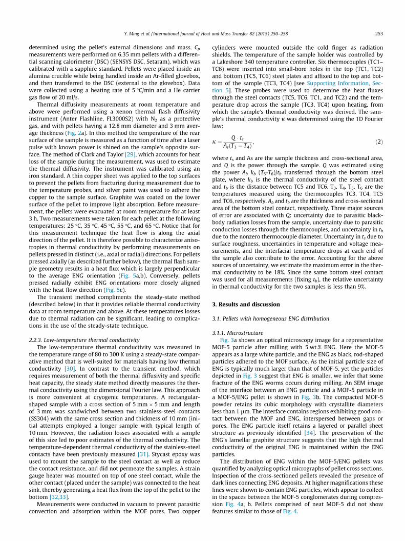
3.1.1. MicrostructureFig. 3a shows an optical microscopy image for a representative
MOF-5 particle after milling with 5 wt.% ENG. Here the MOF-5appears as a large white particle, and the ENG as black, rod-shapedparticles adhered to the MOF surface. As the initial particle size ofENG is typically much larger than that of MOF-5, yet the particlesdepicted in Fig. 3 suggest that ENG is smaller, we infer that somefracture of the ENG worms occurs during milling. An SEM imageof the interface between an ENG particle and a MOF-5 particle ina MOF-5/ENG pellet is shown in Fig. 3b. The compacted MOF-5powder retains its cubic morphology with crystallite diametersless than 1 lm. The interface contains regions exhibiting good con-tact between the MOF and ENG, interspersed between gaps orpores. The ENG particle itself retains a layered or parallel sheetstructure as previously identified [34]. The preservation of theENG’s lamellar graphite structure suggests that the high thermalconductivity of the original ENG is maintained within the ENGparticles.
The distribution of ENG within the MOF-5/ENG pellets wasquantified by analyzing optical micrographs of pellet cross sections.Inspection of the cross-sectioned pellets revealed the presence ofdark lines connecting ENG deposits. At higher magnifications theselines were shown to contain ENG particles, which appear to collectin the spaces between the MOF-5 conglomerates during compres-sion Fig. 4a, b. Pellets comprised of neat MOF-5 did not showfeatures similar to those of Fig. 4.
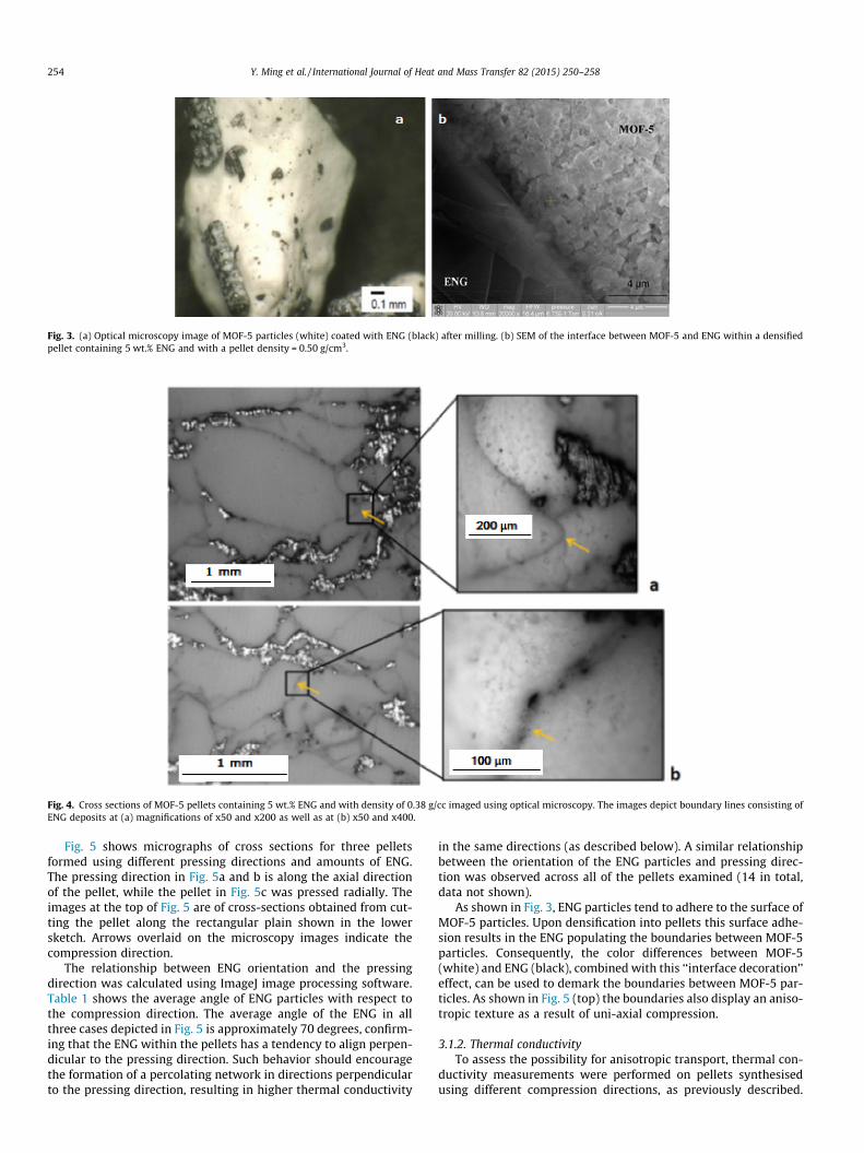
Fig. 3. (a) Optical microscopy image of MOF-5 particles (white) coated with ENG (black) after milling. (b) SEM of the interface between MOF-5 and ENG within a densifiedpellet containing 5 wt.% ENG and with a pellet density = 0.50 g/cm3.
Fig. 4. Cross sections of MOF-5 pellets containing 5 wt.% ENG and with density of 0.38 g/cc imaged using optical microscopy. The images depict boundary lines consisting ofENG deposits at (a) magnifications of x50 and x200 as well as at (b) x50 and x400.
254 Y. Ming et al. / International Journal of Heat and Mass Transfer 82 (2015) 250–258
Fig. 5 shows micrographs of cross sections for three pelletsformed using different pressing directions and amounts of ENG.The pressing direction in Fig. 5a and b is along the axial directionof the pellet, while the pellet in Fig. 5c was pressed radially. Theimages at the top of Fig. 5 are of cross-sections obtained from cut-ting the pellet along the rectangular plain shown in the lowersketch. Arrows overlaid on the microscopy images indicate thecompression direction.
The relationship between ENG orientation and the pressingdirection was calculated using ImageJ image processing software.Table 1 shows the average angle of ENG particles with respect tothe compression direction. The average angle of the ENG in allthree cases depicted in Fig. 5 is approximately 70 degrees, confirm-ing that the ENG within the pellets has a tendency to align perpen-dicular to the pressing direction. Such behavior should encouragethe formation of a percolating network in directions perpendicularto the pressing direction, resulting in higher thermal conductivity
in the same directions (as described below). A similar relationshipbetween the orientation of the ENG particles and pressing direc-tion was observed across all of the pellets examined (14 in total,data not shown).
As shown in Fig. 3, ENG particles tend to adhere to the surface ofMOF-5 particles. Upon densification into pellets this surface adhe-sion results in the ENG populating the boundaries between MOF-5particles. Consequently, the color differences between MOF-5(white) and ENG (black), combined with this ‘‘interface decoration’’effect, can be used to demark the boundaries between MOF-5 par-ticles. As shown in Fig. 5 (top) the boundaries also display an aniso-tropic texture as a result of uni-axial compression.
3.1.2. Thermal conductivityTo assess the possibility for anisotropic transport, thermal con-
ductivity measurements were performed on pellets synthesisedusing different compression directions, as previously described.
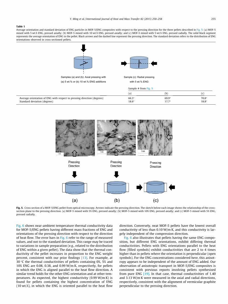
Fig. 5. Cross section of a MOF-5/ENG pellet from optical microscopy. Arrows indicate the pressing direction. The sketch below each image shows the relationship of the cross-section plane to the pressing direction. (a) MOF-5 mixed with 5% ENG, pressed axially; (b) MOF-5 mixed with 10% ENG, pressed axially; and (c) MOF-5 mixed with 5% ENG,pressed radially.
Table 1Average orientation and standard deviation of ENG particles in MOF-5/ENG composites with respect to the pressing direction for the three pellets described in Fig. 5: (a) MOF-5mixed with 5 wt.% ENG, pressed axially; (b) MOF-5 mixed with 10 wt.% ENG, pressed axially; and (c) MOF-5 mixed with 5 wt.% ENG, pressed radially. The solid black segmentrepresents the average orientation of ENG in the pellet. Black arrows and the dashed line represent the pressing direction. The standard deviation refers to the distribution of ENGorientations observed in cross-sectioned pellets.
Sample (c): Radial pressing
with 5 wt.% ENG
Samples (a) and (b): Axial pressing with
(a) 5 wt.% or (b) 10 wt.% ENG additions
Y. Ming et al. / International Journal of Heat and Mass Transfer 82 (2015) 250–258 255
Fig. 6 shows near-ambient temperature thermal conductivity datafor MOF-5/ENG pellets having different mass fractions of ENG andorientations of the pressing direction with respect to the directionof heat flow. The error bars in Fig. 6 refer to the range of measuredvalues, and not to the standard deviation. This range may be tracedto variations in sample preparation (e.g., related to the distributionof ENG within a given pellet). The data show that the thermal con-ductivity of the pellet increases in proportion to the ENG weightpercent, consistent with our prior findings [13]. For example, at30 �C the thermal conductivities of pellets containing 0%, 5% and10% ENG are 0.08, 0.38, and 0.99 W/m K, respectively, for pelletsin which the ENG is aligned parallel to the heat flow direction. Asimilar trend holds for the other ENG orientation and at other tem-peratures. As expected, the highest conductivity (0.99 W/m K) isfound for pellets containing the highest concentration of ENG(10 wt.%), in which the ENG is oriented parallel to the heat flow
direction. Conversely, neat MOF-5 pellets have the lowest overallconductivity of less than 0.10 W/m K, and this conductivity is lar-gely independent of the compression direction.
Fig. 6 also illustrates that pellets having the same ENG compo-sition, but different ENG orientations, exhibit differing thermalconductivities. Pellets with ENG orientations parallel to the heatflow (filled symbols) exhibit conductivities that are 2 to 4 timeshigher than in pellets where the orientation is perpendicular (opensymbols). For the ENG concentrations considered here, this anisot-ropy appears to be independent of the amount of ENG added. Ourobservation of anisotropic transport in MOF-5/ENG composites isconsistent with previous reports involving pellets synthesisedfrom pure ENG [19]. In that case, thermal conductivities of 1.40and 3.13 W/m K were measured in the axial and radial directions,respectively, consistent with the alignment of vermicular graphiteperpendicular to the pressing direction.
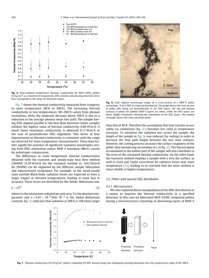
Fig. 6. Near-ambient temperature thermal conductivity for MOF-5/ENG pellets(0.4 g/cm3) as a function of temperature, ENG content, and pressing direction. Errorbars correspond to the range of measured values.
Fig. 8. (Left) Optical microscopy image of a cross-section of a MOF-5 pelletcontaining �5 wt.% ENG in a layered distribution. The graph shows the cross sectionof pellet after being cut perpendicular to the ENG layers; the top and bottomsurfaces of pellet are labeled. MOF-5 layers are white, while the ENG layers areblack. (Right) Schematics showing the orientation of the ENG layers. The dashedrectangle shows the cross-sectional plane.
256 Y. Ming et al. / International Journal of Heat and Mass Transfer 82 (2015) 250–258
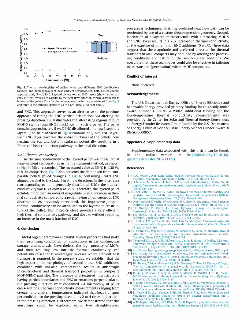
Fig. 7 shows the thermal conductivity measured from cryogenicto room temperature (80 K to 300 K). The increasing thermalconductivity at low temperatures (80–200 K) arises from phononexcitations, while the moderate decrease above 200 K is due to areduction in the average phonon mean free path. The sample hav-ing ENG aligned parallel to the heat flow direction (white sample)exhibits the highest value of thermal conductivity 0.68 W/m K. Amuch lower maximum conductivity is observed 0.17 W/m K inthe case of perpendicular ENG alignment. This factor of fourimprovement in thermal conductivity is consistent with the rangewe observed for room temperature measurements. These data fur-ther signify the presence of significant transport anisotropies aris-ing from ENG orientation and/or MOF-5 boundary effects causedby anisotropic compression.
The differences in room temperature thermal conductivitiesobtained with the transient and steady-state heat flow method(SSHFM) (0.38 W/m K for the transient method vs. 0.62 W/m Kfor SSHFM) can be explained by the different sample fabricationand measurement techniques. For example, in the stead-steadystate method Black-body radiation losses are expected to have alarger impact at elevated temperatures, leading to some loss inaccuracy. These losses are described by the Stefan–Boltzmann law,
J ¼ rT4; ð3Þ
where j is the total power radiated per unit area, T is the absolute tem-perature and r = 5.67 � 10�8 Wm�2K�4 is the Stefan–Boltzmannconstant. Eq. (3) indicates that radiation at 300 K is 198 times larger
Fig. 7. Thermal conductivity of 0.35 g/cm3 pellets containing 5% ENG formed using
than that at 80 K. Therefore the assumption that heat transfer occurssolely via conduction (Eq. (2)) becomes less valid as temperatureincreases. To minimize the radiation loss across the sample, thelength of the sample in Fig. 2c was reduced (by cutting) in order todecrease the heat path length between the two steel contacts.However, the cutting process increases the surface roughness of thepellet, thus introducing uncertainty in ts in Eq. (2). The Stycast epoxyaccumulated in the hollow part of the sample will also contribute tothe error of the calculated thermal conductivity. On the other hand,the transient method employs a sample with a very flat surface, aswell as Clark and Taylor corrections for radiative losses near roomtemperature [35], leading us to conclude that the latter method ismore reliable at higher temperatures.
3.2. Pellets with layered ENG distribution
3.2.1. MicrostructureWe also explored direct manipulation of the ENG distribution as
a means to improve the thermal conductivity in a specifieddirection. In this case we fabricated MOF-5/ENG composite pelletshaving a microstructure consisting of alternating layers of MOF-5
Heat Pressing direction
Pressing direction
two orthogonal pressing directions over the temperature range of 80–300 K.
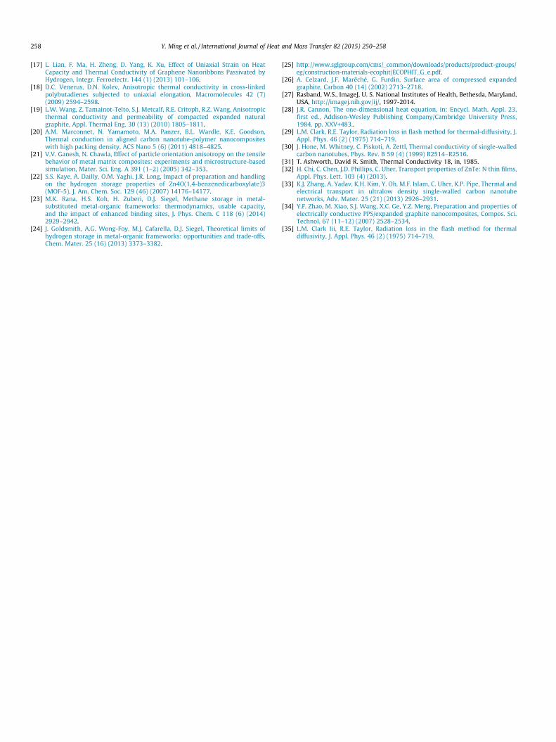
Top
Bottom
Fig. 9. Thermal conductivity of pellets with two different ENG distributions(layered and homogeneous) at near-ambient temperatures. Both pellets containapproximately 5 wt.% ENG. Layered pellets contain ENG layers (shown schemati-cally at right) which are parallel to the heat flow direction, which is from top tobottom of the pellets. Data for the homogeneous pellets are reproduced from Fig. 5,and refer to the samples identified as ‘‘5% ENG parallel to heat flow.’’.
Y. Ming et al. / International Journal of Heat and Mass Transfer 82 (2015) 250–258 257
and ENG. This approach serves as an alternative to the previousapproach of tuning the ENG particle orientations via altering thepressing direction. Fig. 8 illustrates the alternating regions of pureMOF-5 (white) and ENG (black) within such a pellet. The pelletcontains approximately 5 wt.% ENG distributed amongst 3 separatelayers. (The field of view in Fig. 8 contains only one ENG layer.)Each ENG layer traverses the entire thickness of the pellets, con-necting the top and bottom surfaces, potentially resulting in a‘‘shorted’’ heat conduction pathway in the axial direction.
3.2.2. Thermal conductivityThe thermal conductivity of the layered pellet was measured at
near-ambient temperatures using the transient method, as shownin Fig. 9 (filled rectangles). The measured value at 35 �C is 4.35 W/m K. In comparison, Fig. 9 also presents the data taken from com-parable pellets (filled triangles in Fig. 6) containing 5 wt.% ENGaligned parallel to the (axial) heat flow direction. In the latter case(corresponding to homogeneously distributed ENG), the thermalconductivity was 0.30 W/m K at 35 �C. Therefore, the layered pelletexhibits more than an order of magnitude (�20x) increase in ther-mal conductivity compared to a pellet having a homogeneous ENGdistribution. As previously mentioned, this impressive jump inthermal conductivity can be attributed to the layered microstruc-ture of the pellet. This microstructure provides a very efficient,high thermal conductivity pathway, and does so without requiringan increase in the mass fraction of ENG.
4. Conclusion
Metal organic frameworks exhibit several properties that makethem promising candidates for applications in gas capture, gasstorage, and catalysis. Nevertheless, the high porosity of MOFs,and their resulting low intrinsic thermal conductivity, canpotentially offset these advantages in cases where efficient heattransport is required. In the present study we establish that thehigh-aspect ratio morphology of second-phase ENG additions,combined with uni-axial compression, results in anisotropicmicrostructural and thermal transport properties in compositeMOF-5/ENG particles. The presence of a textured microstructurehaving particle boundaries and ENG orientations perpendicular tothe pressing direction were confirmed via microscopy of pelletcross-sections. Thermal conductivity measurements ranging fromcryogenic to ambient temperatures indicated that heat transportperpendicular to the pressing direction is 2 to 4 times higher thanin the pressing direction. Furthermore, we demonstrated that thisanisotropy could be exploited using two straightforward
processing techniques: First, the preferred heat flow path can bereoriented by use of a custom die/compression geometry. Second,fabrication of a layered microstructure with alternating MOF-5and ENG layers results in a 20x increase in thermal conductivity,at the expense of only minor ENG additions (5 wt.%). These datasuggest that the magnitude and preferred direction for thermaltransport in MOF compacts may be tuned by altering the process-ing conditions and nature of the second-phase additions. Wespeculate that these techniques could also be effective in tailoringmass transport (permeation) within MOF composites.
Conflict of interest
None declared.
Acknowledgements
The U.S. Department of Energy, Office of Energy Efficiency andRenewable Energy provided primary funding for this study underaward number DE-FC36-GO19002. Additional funding for thelow-temperature thermal conductivity measurements wasprovided by the Center for Solar and Thermal Energy Conversion,an Energy Frontier Research Center funded by the U.S. Departmentof Energy, Office of Science, Basic Energy Sciences under Award #DE-SC-0000957.
Appendix A. Supplementary data
Supplementary data associated with this article can be found,in the online version, at http://dx.doi.org/10.1016/j.ijheatmasstransfer.2014.11.053.
References
[1] J.L.C. Rowsell, O.M. Yaghi, Metal-organic frameworks: a new class of porousmaterials, Microporous Mesoporous Mater. 73 (1–2) (2004) 3–14.
[2] U. Mueller, M. Schubert, F. Teich, H. Puetter, K. Schierle-Arndt, J. Pastre, Metal-organic frameworks-prospective industrial applications, J. Mater. Chem. 16 (7)(2006) 626–636.
[3] K. Schlichte, T. Kratzke, S. Kaskel, Improved synthesis, thermal stability andcatalytic properties of the metal-organic framework compound Cu3(BTC)2,Microporous Mesoporous Mater. 73 (1–2) (2004) 81–88.
[4] O.M. Yaghi, M. O’Keeffe, N.W. Ockwig, H.K. Chae, M. Eddaoudi, J. Kim, Reticularsynthesis and the design of new materials, Nature 423 (6941) (2003) 705–714.
[5] L.J. Murray, M. Dinca, J.R. Long, Hydrogen storage in metal-organicframeworks, Chem. Soc. Rev. 38 (5) (2009) 1294–1314.
[6] T.A. Makal, J.-R. Li, W. Lu, H.-C. Zhou, Methane storage in advanced porousmaterials, Chem. Soc. Rev. 41 (23) (2012) 7761–7779.
[7] S. Keskin, T.M. van Heest, D.S. Sholl, Can metal-organic framework materialsplay a useful role in large-scale carbon dioxide separations?, ChemSusChem 3(8) (2010) 879–891
[8] B. Schmitz, U. Müller, N. Trukhan, M. Schubert, G. Férey, M. Hirscher, Heat ofadsorption for hydrogen in microporous high-surface-area materials,ChemPhysChem 9 (15) (2008) 2181–2184.
[9] J. Purewal, D. Liu, A. Sudik, M. Veenstra, J. Yang, S. Maurer, U. Müller, D.J. Siegel,Improved Hydrogen Storage and Thermal Conductivity in High-Density MOF-5Composites, J. Phys. Chem. C 116 (38) (2012) 20199–20212.
[10] http://www.hydrogen.energy.gov/pdfs/review11/st006_van_hassel_2011_o.pdf.[11] B.L. Huang, A.J.H. McGaughey, M. Kaviany, Thermal conductivity of metal-
organic framework 5 (MOF-5): Part I. Molecular dynamics simulations, Int. J.Heat Mass Transfer 50 (3–4) (2007) 393–404.
[12] B.L. Huang, Z. Ni, A. Millward, A.J.H. McGaughey, C. Uher, M. Kaviany, O. Yaghi,Thermal conductivity of a metal-organic framework (MOF-5): Part II.Measurement, Int. J. Heat Mass Transfer 50 (3–4) (2007) 405–411.
[13] D. Liu, J.J. Purewal, J. Yang, A. Sudik, S. Maurer, U. Mueller, J. Ni, D.J. Siegel,MOF-5 composites exhibiting improved thermal conductivity, Int. J. HydrogenEnergy 37 (7) (2012) 6109–6117.
[14] Y. Ming, J. Purewal, D.a. Liu, A. Sudik, C. Xu, J. Yang, M. Veenstra, K. Rhodes, R.Soltis, J. Warner, M. Gaab, U. Müller, D.J. Siegel, Thermophysical properties ofMOF-5 powders, Microporous Mesoporous Mater. 185 (0) (2014) 235–244.
[15] J.J. Purewal, D. Liu, J. Yang, A. Sudik, D.J. Siegel, S. Maurer, U. Müller, Increasedvolumetric hydrogen uptake of MOF-5 by powder densification, Int. J.Hydrogen Energy 37 (3) (2012) 2723–2727.
[16] A. Rodrı́guez Sánchez, H.-P. Klein, M. Groll, Expanded graphite as heat transfermatrix in metal hydride beds, Int. J. Hydrogen Energy 28 (5) (2003) 515–527.
258 Y. Ming et al. / International Journal of Heat and Mass Transfer 82 (2015) 250–258
[17] L. Lian, F. Ma, H. Zheng, D. Yang, K. Xu, Effect of Uniaxial Strain on HeatCapacity and Thermal Conductivity of Graphene Nanoribbons Passivated byHydrogen, Integr. Ferroelectr. 144 (1) (2013) 101–106.
[18] D.C. Venerus, D.N. Kolev, Anisotropic thermal conductivity in cross-linkedpolybutadienes subjected to uniaxial elongation, Macromolecules 42 (7)(2009) 2594–2598.
[19] L.W. Wang, Z. Tamainot-Telto, S.J. Metcalf, R.E. Critoph, R.Z. Wang, Anisotropicthermal conductivity and permeability of compacted expanded naturalgraphite, Appl. Thermal Eng. 30 (13) (2010) 1805–1811.
[20] A.M. Marconnet, N. Yamamoto, M.A. Panzer, B.L. Wardle, K.E. Goodson,Thermal conduction in aligned carbon nanotube-polymer nanocompositeswith high packing density, ACS Nano 5 (6) (2011) 4818–4825.
[21] V.V. Ganesh, N. Chawla, Effect of particle orientation anisotropy on the tensilebehavior of metal matrix composites: experiments and microstructure-basedsimulation, Mater. Sci. Eng. A 391 (1–2) (2005) 342–353.
[22] S.S. Kaye, A. Dailly, O.M. Yaghi, J.R. Long, Impact of preparation and handlingon the hydrogen storage properties of Zn4O(1,4-benzenedicarboxylate)3(MOF-5), J. Am. Chem. Soc. 129 (46) (2007) 14176–14177.
[23] M.K. Rana, H.S. Koh, H. Zuberi, D.J. Siegel, Methane storage in metal-substituted metal-organic frameworks: thermodynamics, usable capacity,and the impact of enhanced binding sites, J. Phys. Chem. C 118 (6) (2014)2929–2942.
[24] J. Goldsmith, A.G. Wong-Foy, M.J. Cafarella, D.J. Siegel, Theoretical limits ofhydrogen storage in metal-organic frameworks: opportunities and trade-offs,Chem. Mater. 25 (16) (2013) 3373–3382.
[25] http://www.sglgroup.com/cms/_common/downloads/products/product-groups/eg/construction-materials-ecophit/ECOPHIT_G_e.pdf.
[26] A. Celzard, J.F. Marêché, G. Furdin, Surface area of compressed expandedgraphite, Carbon 40 (14) (2002) 2713–2718.
[27] Rasband, W.S., ImageJ, U. S. National Institutes of Health, Bethesda, Maryland,USA, http://imagej.nih.gov/ij/, 1997-2014.
[28] J.R. Cannon, The one-dimensional heat equation, in: Encycl. Math. Appl. 23,first ed., Addison-Wesley Publishing Company/Cambridge University Press,1984. pp. XXV+483..
[29] L.M. Clark, R.E. Taylor, Radiation loss in flash method for thermal-diffusivity, J.Appl. Phys. 46 (2) (1975) 714–719.
[30] J. Hone, M. Whitney, C. Piskoti, A. Zettl, Thermal conductivity of single-walledcarbon nanotubes, Phys. Rev. B 59 (4) (1999) R2514–R2516.
[31] T. Ashworth, David R. Smith, Thermal Conductivity 18, in, 1985.[32] H. Chi, C. Chen, J.D. Phillips, C. Uher, Transport properties of ZnTe: N thin films,
Appl. Phys. Lett. 103 (4) (2013).[33] K.J. Zhang, A. Yadav, K.H. Kim, Y. Oh, M.F. Islam, C. Uher, K.P. Pipe, Thermal and
electrical transport in ultralow density single-walled carbon nanotubenetworks, Adv. Mater. 25 (21) (2013) 2926–2931.
[34] Y.F. Zhao, M. Xiao, S.J. Wang, X.C. Ge, Y.Z. Meng, Preparation and properties ofelectrically conductive PPS/expanded graphite nanocomposites, Compos. Sci.Technol. 67 (11–12) (2007) 2528–2534.
[35] L.M. Clark Iii, R.E. Taylor, Radiation loss in the flash method for thermaldiffusivity, J. Appl. Phys. 46 (2) (1975) 714–719.


![J org Pretz arXiv:2005.12203v1 [physics.class-ph] 25 May 2020 › pdf › 2005.12203.pdf · (t)/ m mass 1 mass 2 mass 3 mass 4 mass 5 mass 6 mass 7 mass 8 mass 9 mass 10 Figure 2](https://img.pdfslide.us/doc/110x75/5f1ec529f26656179f60ee75/j-org-pretz-arxiv200512203v1-25-may-2020-a-pdf-a-200512203pdf-t.jpg)


![Electrochemistry of Magnesium Electrolytes in Ionic ...djsiege/Energy_Storage_Lab/...compounds such as MgCl 2 or Mg(ClO 4) 2] are less likely to promote Mg plating due to the strong](https://img.pdfslide.us/doc/110x75/60a8cddb009cda3e59623712/electrochemistry-of-magnesium-electrolytes-in-ionic-djsiegeenergystoragelab.jpg)
![Compositional evolution of Q-phase precipitates in an ...djsiege/Energy_Storage_Lab/...Al–Cu–Mg–Ag alloys [26]. More recently, we have employed APT to study the compositional](https://img.pdfslide.us/doc/110x75/5eb81a363412d64d4665b4a8/compositional-evolution-of-q-phase-precipitates-in-an-djsiegeenergystoragelab.jpg)