Embed Size (px)
Citation preview
International Journal of Heat and Mass Transfer 86 (2015) 519–530
Contents lists available at ScienceDirect
International Journal of Heat and Mass Transfer
journal homepage: www.elsevier .com/locate / i jhmt
Heat and mass transfer mechanisms of a self-sustained thermally drivenoscillating liquid–vapour meniscus
http://dx.doi.org/10.1016/j.ijheatmasstransfer.2015.03.0150017-9310/� 2015 Elsevier Ltd. All rights reserved.
⇑ Corresponding author.E-mail address: [email protected] (S. Khandekar).
Manoj Rao a, Frédéric Lefèvre a, Sameer Khandekar b,⇑, Jocelyn Bonjour a
a CETHIL UMR5008, Université de Lyon, CNRS, INSA-Lyon, Univ. Lyon 1, F-69621, Villeurbanne, Franceb Department of Mechanical Engineering, Indian Institute of Technology Kanpur, Kanpur 208016, India
a r t i c l e i n f o
Article history:Received 2 December 2014Received in revised form 22 February 2015Accepted 6 March 2015Available online 28 March 2015
Keywords:Pulsating heat pipeOscillating meniscusLiquid film drainageEvaporationCondensationContact line dynamicsModelling
a b s t r a c t
Self-sustained thermally-induced oscillations of a meniscus in a two-phase system, consisting of a liquidplug and a vapour bubble in a capillary tube, are studied. This system represents the simplest ‘unit-cell’version of a pulsating heat pipe (PHP). An experimental setup has been built to visualise and record themeniscus oscillations and the thin liquid film that is laid on the wall when the meniscus leaves theevaporator. The pressure and temperature of the vapour are also simultaneously measured. When thetemperature difference between the heat source and the heat sink increases, different meniscusdynamics, having excellent repeatability, is observed. The experimental results clearly demonstrate thatevaporation of the liquid film is responsible for these patterns. The different components of evaporationand condensation processes are critically analysed. Two different modes of evaporation are observedinside the system: one at the triple-line and one at the liquid–vapour interface. Considering that no com-prehensive model of PHP system is available, the conclusions and directions provided in this study areimportant for building a broader understanding.
� 2015 Elsevier Ltd. All rights reserved.
1. Introduction
A pulsating heat pipe (PHP) is essentially a passive two-phaseheat transfer device, which also belongs to a special category ofwickless heat pipes [1,2]. From a technological point of view, thisthermal transport system is very simple and can be consideredas almost costless [1] compared to other heat transport devices.Therefore, research on PHP as a system has been a point of interestin the recent past and its potential applications in many passiveheat transport situations has been extensively studied [3–7].However, in contrast to large availability of system level studieson PHPs in the literature, the nuances of its operating principlesand associated physics are not well understood, which thwartsthe large scale industrial acceptability of PHPs.
A PHP consists of a simple capillary tube, with no wick struc-ture, bent into many turns, and partially filled with a working fluid.When the temperature difference between the heat source and theheat sink exceeds a certain threshold, the vapour bubbles and liq-uid plugs present inside the capillary tube begin to auto-oscillate,back and forth, which leads to unique heat transfer characteristics.Heat is thus passively transferred, not only by latent heat exchange
like in conventional heat pipes, but also by sensible heat transferbetween the wall and the fluid. This complex internal thermo-hydrodynamic transport process is known as the self-sustainedthermally driven oscillating two-phase Taylor bubble flow.
Research on PHPs has seen an unprecedented increase duringthe last 15 years, almost 25 years after the system has beenpatented in its most popular layout by Akachi [8,9].Unfortunately, major part of the literature does not provide univer-sally applicable generic knowledge base on these systems; it gen-erally focuses on one particular PHP structure or type, designedfor a specific application. In these type of works having a systemlevel approach, the PHP is usually characterised by the tempera-ture difference measured between the condenser and the evap-orator section, for a given applied heat flux. Every such PHPdesign has its own geometrical and thermophysical properties(inner and outer diameters, length, closed or open-loop devices,evaporator, condenser and adiabatic lengths, number of turns,material of the tube, etc.) and is filled with a specific working fluidhaving its own thermophysical properties (latent heat, wettabilityand for both vapour and liquid phases: thermal conductivity andcapacity, density, viscosity, etc.), and is tested in specific experi-mental conditions (heat load at the evaporator, ambient and con-denser temperatures, etc.). The number of relevant parameters tocharacterise a PHP is therefore so large that it is difficult to
Nomenclature
â average acceleration of meniscus (m/s2)Bo Bond number (q � â � D2/r)Ca Capillary number (lU/r)D diameter (m)h heat transfer coefficient (W/m2 K)hlv latent heat (J/kg)K thermal conductance (W/K)L length (m)m mass (kg)_m mass flow rate (kg/s)
M molecular weight (kg/mol)P pressure (Pa)R radius (m)�R universal gas constant (J/mol K)t time (s)T temperature (�C or K)x coordinate (m)U velocity (m/s)V volume (m3)
Greek symbolsd film thickness (m)k thermal conductivity (W/m K)l dynamic viscosity (Pa-s)q density (kg/m3)r surface tension (N/m)
Subscriptsa adiabaticc condensercond condensatione evaporatorf filmi internall liquidmax maximumsat saturationv vapour0 initial
520 M. Rao et al. / International Journal of Heat and Mass Transfer 86 (2015) 519–530
explicitly discriminate the effect of one parameter among theothers in this type of experiments. As a result, one can find severalpapers [1] dealing with the same parameters and often having con-flicting or repetitive conclusions. To overcome these difficulties,some authors developed non-dimensional expressions based ondifferent numbers like the Jacob, the Karman, the Prandtl or theKutateladze numbers and taking into account the number of turns[10]. Nevertheless, this approach has also failed so far to provide auniversal understanding of the PHP because the basic physical phe-nomena and the extent of parameters responsible for systemdynamics are not yet well understood.
Research at the local scale (i.e., at the scale of one bubble andone liquid plug), although few, were addressed quite early, in orderto augment the knowledge on basic phenomena which are respon-sible for the oscillations and the heat transfer in the system. From amodelling perspective, this approach was initiated by Zhang et al.[11,12] and Dobson [13,14], who studied theoretically the govern-ing mechanisms of a single branch of the PHP, consisting of onevapour bubble and one liquid slug. Das et al. [24] developed a moresophisticated approach which included the two-phase equilibriumphysics that occurs locally at the liquid vapour-interface, especiallyalong the time-varying wetting thin film. Such a film gets laiddown by the liquid plug during its journey from the evaporatortowards the condenser and through which the major part of heatand mass transfer occurs. This film was shown to be one of themajor phenomena responsible for the large amplitude oscillationsobserved in the system. In this work, an instability analysis of thissystem was also performed. The local scale modelling has nowbeen extended to several PHP branches with many liquid plugsand vapour bubbles [15–19].
Looking at the literature related to experimental studies onPHPs, the local approach to study its characteristics is compara-tively even scarcer. Local heat transfer measurements in non-boil-ing Taylor bubble flow, in the context of pulsating heat pipes havebeen recently addressed. Many research groups have shown thatthe flow field in single-phase liquid flows gets significantly modi-fied by slipping Taylor bubbles of gas/vapour through it, whicheventually leads to enhanced heat transfer [20–22]. Continuingon these lines, Mehta and Khandekar [23] recently studied the heattransfer characteristics of pulsating Taylor bubble-train flow in
square mini-channels using infra-red thermography, the frequencyof imposed flow fluctuations being similar to those encountered inPHPs. The main objective of the study was to observe the effects ofexternally imposed pulsations on local heat transfer taking place ina unit cell, comprising of a Taylor liquid slug trapped between twoadjacent gas bubbles. The controlling parameter of the study wasliquid and gas flow rates and imposed flow frequencies. The studyindicated that the distribution of liquid-slugs and vapour bubblesis one of the important parameter for improving thermal perfor-mance of PHPs. Perturbing the Taylor bubble-train flow withimposed frequencies may conditionally lead to enhancement inthe heat transfer, in comparison to steady continuous Taylor bub-ble-train. The sensible heating/cooling transport capability of theliquid slugs can be altered by controlling the wake generated bythe adjoining Taylor bubbles. Interfacial slip created by intermit-tent flow conditions, was the major cause for heat transferenhancement.
Earlier, in 2010, Das et al. [24] presented the first experimentaldata of the simplest ‘unit-cell’ version of a pulsating heat pipe, con-sisting of one liquid plug and one vapour bubble. Their experimen-tal setup was closer to a real-PHP and also, the theoreticalconfiguration previously studied by Dobson [13,14]. It consistedof a capillary tube closed at one end and connected to a reservoirmaintained at a constant pressure at the other end. A single liquidplug adjoining a vapour bubble was made to thermally auto-oscil-late inside this tube, which was heated on one side and cooleddown on the other side, thereby creating a continuous cycle ofevaporation and condensation. The movement of the meniscuswas recorded in the cooled section of the tube, while the heatedsection, made of copper, was opaque. The vapour pressure was alsomeasured during the oscillations. A similar experiment performedin cryogenic conditions was presented by Bonnet et al. [25] in 2011and Gully et al. [26] in 2013. Compared to the previous experiment,their system was totally opaque; a thin micro-thermocouple wasused to measure the time-varying temperature of the vapour,which showed that the vapour plug is superheated in this singlebranch PHP experiment. This is a major result as this hypothesishad never been verified before, although it was proposed earlierby Khandekar et al. [27]. Some important experimental limitationswere present in the work of Das et al. [24]. The experimental setup
M. Rao et al. / International Journal of Heat and Mass Transfer 86 (2015) 519–530 521
was not fully transparent, except the condenser section as indi-cated earlier, and therefore the internal hydrodynamic phenomenacould not be observed in totality. Besides, the connection betweenthe opaque metal evaporator and the glass condenser section, pre-sented minor flow perturbations having potential impact on thesmooth meniscus movement to a certain extent. Furthermore,experiments were done without any synchronization of the inter-nal pressure measurements with the videography.
In 2013, Rao et al. [28] made the pressure measurements in theevaporator section, fully synchronized in real-time with the highspeed videography camera. This singular improvement of the setupled to a drastic improvement in the overall understanding of thecomplex liquid film evaporation and ensuing pressure fluctuationsinside the unit-cell. Contrary to obvious interpretations, maximumpressure in the vapour bubble was achieved in the downwardstroke of the meniscus, rather than its upward stroke. Thus, itwas concluded that the system dynamics cannot be compared withgas-compression cycles; the presence of vapour, coupled withtransient phase-change processes, give rise to unique transportphenomena. In this paper, new experimental data are presentedusing the same experimental bench of Rao et al. [28]. A second highspeed camera is used to record the evaporation of the wetting filmlaid down by the meniscus when it leaves the evaporator. The cap-tured temporal data enable to bring some very useful informationand perspective to characterise the heat and mass transfer mecha-nisms of a self-sustained thermally driven oscillating two-phasesystem, such as a PHP. The different components of evaporationand condensation processes inside the system are critically anal-ysed. Two different modes of evaporation are observed inside thesystem: one at the triple-line and one at the liquid–vapour inter-face. The dynamics of the thin film is theoretically described usingthe mass and energy balance equations coupled to the experimen-tal data. This new information is vital for furthering the develop-ment of a realistic and comprehensive PHP mathematical model.
2. The ‘unit-cell’ experiment
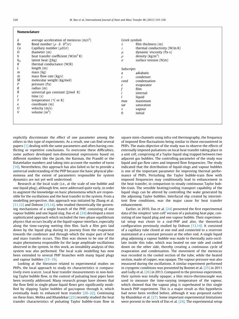
The experimental set-up is presented in Fig. 1. As noted, it is animproved version of a previous experimental design presented byDas et al. [24] and further used by Rao et al. [28]. It mimics the
Fig. 1. (a) Schematic of the experimental set-up for obtaining self-sustained thermally dplug. (b) Details of the unit-cell highlighting the characteristic lengths and relevant par
basic unit-cell of a PHP, with one liquid plug and one vapour bub-ble, located in a vertical capillary tube of circular cross-section. Thetransparent capillary tube of inner diameter 2.0 mm, made of glass,is closed at one side and connected to a reservoir maintained at aconstant pressure at the other side. The liquid plug oscillatesbetween a heat source located near the upper closed side (lengthLe = 20 cm) and a heat sink located near the bottom reservoir(length Lc = 20 cm). In between, a small adiabatic section of lengthLa = 1 cm separates the heat source and the heat sink. In the follow-ing, the heat source and the heat sink will often be termed ‘evap-orator’ and ‘condenser’, from an analogy with conventional heatpipes. One should however be aware that strictly speaking, thisterminology is not fully adequate in the present system, since con-densation can also occur in the evaporator as it has been shownearlier by Rao et al. [28] too, and further corroborated by theresults of the present study.
The evaporator and the condenser are transparent heat exchan-gers, whose temperature is controlled by two thermostatic bathswith an overall accuracy of ±1 �C. A third thermostatic bath is usedto control the temperature of the reservoir (±0.2 �C), and thus itssaturation pressure. The two-phase oscillatory flow is charac-terised by vapour pressure measurements as well as meniscus dis-placement measurements. An absolute pressure sensor (suppliedby Kistler
�, piezo-resistive sensor type 4007B, operating range of
0–5 bar, accuracy ±0.1% of full-scale reading) is located at theclosed end of the tube. Two high speed cameras (Photron-Fastcam
�1024-PCI and SA-3, respectively) are simultaneously used
to record the meniscus displacement and movement of the triple-line. A K-type thermocouple of diameter 80 lm is also insertedfrom the top of the capillary tube to measure the temperature ofthe vapour, as shown. The pressure and temperature measurementis synchronized with the two video cameras with external trigger.Before the experiments, the system is completely evacuated toremove the non-condensable gases using a vacuum pump (<10�5
mbar). The reservoir is then filled with the working fluid, i.e.,FC72. The volume of the liquid reservoir is exceedingly large ascompared to that of the capillary tube. This ensures that any inter-nal meniscus oscillations have a negligible effect on the reservoirstatic pressure. The capillary tube always remains dipped insidethe liquid irrespective of level of the liquid meniscus in it during
riven oscillating flow of a ‘unit-cell’ consisting of one vapour bubble and one liquidameters.
522 M. Rao et al. / International Journal of Heat and Mass Transfer 86 (2015) 519–530
the experiment. The change in liquid level affects the hydrostaticpressure at the outlet of the tube, but in third place of decimal,as the height of liquid above the tube exit is designed to be lowerthan 100 mm.
2.1. Results and discussion
Experimental results are discussed for various operating bound-ary conditions. The reservoir is maintained at a constant pressureof 0.5 bar, corresponding to a saturation temperature of 37.2 �C.The evaporator temperature Te is kept constant at 46 �C whilethe condenser temperature Tc is varied from 0 to 32 �C. It isobserved that when Tc is kept below 16 �C (large temperature dif-ference between the evaporator and condenser) or above 28 �C(low temperature difference between the evaporator and con-denser) the meniscus moves rather randomly and hence, it is veryhard to obtain repeatability in results. For the condenser tempera-ture in between 16 and 28 �C systematic and repeatable oscilla-tions of pressure and meniscus movement are observed.Therefore, the results presented in the next sections are taken inthis range to arrive at meaningful conclusions which can con-tribute in attaining the objectives of this research.
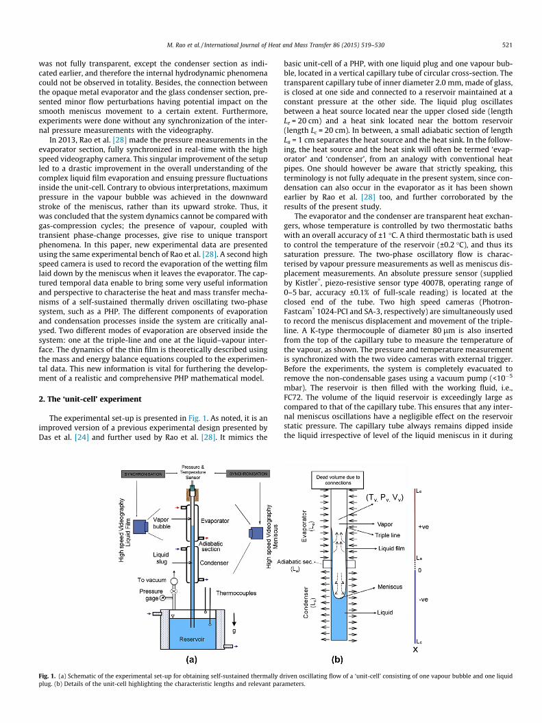
2.1.1. Meniscus oscillation with pressure variationFig. 2 shows the temporal variation of vapour pressure in the
vapour bubble, along with the location of the meniscus and the tri-ple-line, for four cases of the experimentally applied boundaryconditions (Te = 46 �C and Tc = 16, 20, 24 and 28 �C, respectively).The location x = 0 corresponds to the bottom of the adiabatic sec-tion. Locations defined by x > La are in the evaporator section whilethose defined by x < 0 are in the condenser section. Three complete
Fig. 2. Temporal variations of pressure (right ordinate axis) in the vapour bubble along waxis, dotted line) for experimental condition of Te = 46 �C and (a) Tc = 16 �C, (b) Tc = 20 �C
meniscus motion cycles are presented for each condenser tempera-ture. It is observed that meniscus movement and pressure varia-tion are quasi-periodic and nicely repeatable for all of the cases.When the meniscus moves towards the condenser (downwardmotion), a thin liquid film gets drained or laid on the tube wall.As it will be explained later, this film drainage by the movingmeniscus is responsible for the large amount of vapour generationat the evaporator, which, in turn, leads to the oscillation of the liq-uid plug.
By looking at the video of meniscus motion, it is possible to dis-tinctly observe three different zones inside the tube: a dark zonecorresponding to the liquid plug, a clear zone corresponding tothe vapour slug, and an in-between zone where the contrast is nei-ther dark nor clear that corresponds to this thin liquid film, whichgets laid down during meniscus downward motion. Furthermore,under proper lighting conditions and controlled focus, it is alsopossible to clearly observe the liquid film vanishing with time,i.e., evaporation of the film from the glass surface is unmistakablyrecorded. The movement of the triple-line towards the condenseris also clearly observable. We consider that the liquid film vanisheswhen the contrast value observed on the video is similar to thecontrast value due to the vapour. However, as the contrast dependson the thickness of the liquid film, the sensitivity of the camera isprobably not able to distinguish film-remnants which are extre-mely thin. Therefore, subsequent analysis is based till the locationwhere the difference of contrast is just vanishing. However, oneshould keep in mind that the absence of explicit quantitative datapoints does not mean with certainty that the liquid film has indeedtotally vanished; a few monolayers of liquid may still be remain-ing. Nevertheless, the recorded information certainly enables tobring some essential information for qualitative interpretations.
ith location of meniscus (left ordinate axis, solid line) and triple-line (left ordinate, (c) Tc = 24 �C and (d) Tc = 28 �C.
M. Rao et al. / International Journal of Heat and Mass Transfer 86 (2015) 519–530 523
For Tc = 16 �C (Fig. 2a), Tc = 20 �C (Fig. 2b) and Tc = 24 �C (Fig. 2c),the meniscus cycle consists of one full stroke inside the evaporatorfollowed by two smaller strokes in the condenser section. Duringthe downward stroke of the meniscus, as noted earlier, it laysdown a thin liquid film. Evaporation of this film adds mass to thevapour space and helps in increasing the vapour pressure. Untilthe time the liquid film laid down by the downward movingmeniscus is completely evaporated, the meniscus is not able tore-enter the evaporator, and thus moves back again twice intothe condenser. Thus, two strokes are seen to occur in the condensersection. The meniscus re-enters the evaporator section, after thesecond stroke in the condenser is over, and then the quasi-periodiccycle continues. The maximum high level reached by the meniscusinside the evaporator is rather constant and close to x = 80 mm forthe different condenser temperatures. This tends to suggest thatthe amount of vapour generated during one cycle at the evaporatoris rather constant, since it is proportional to the length of the liquidfilm drained by the meniscus in the evaporator. Conversely, themaximum level reached by the meniscus inside the condenserincreases with the increase of Tc during the first stroke inside themeniscus. Indeed, for smaller condenser temperatures (larger tem-perature difference), a smaller heat exchange surface area is neces-sary to condense the vapour generated by the evaporation of theliquid film. The second stroke in the condenser is always shorterthan the first one, which can be explained by a smaller amountof vapour generated in the evaporator (the last remnant of thedisappearing liquid film), as the remaining liquid film length ismuch smaller at the end of a cycle. One can also observe that thecycle time-period slightly increases with the increase of Tc.
The qualitative behaviour of the meniscus oscillatory motion isquite different for Tc = 28 �C; the meniscus oscillation cycle consist-ing of a single to-fro stroke in the evaporator, followed by onestroke in the condenser section. Therefore, the net time period ofone oscillation cycle is also smaller than for the other condensertemperatures. One can also observe that the amplitude of the sig-nal is much smaller in both the condenser and the evaporator.Above a condenser temperature of 28 �C, the energy of the systemis not sufficient to maintain the oscillations. It was not possible todistinguish clearly the triple-line evaporation in that case becausethe length of the film formed due to drainage was very short, com-pared to other condenser temperatures. Lastly, comparing thepressure signal for the four graphs (Fig. 2a–d), shows the decreaseof its amplitude with the decrease of the difference between Te andTc. The maximum of amplitude varies from 0.16 to 0.06 bar, whenTc varies from 16 to 28 �C, respectively.
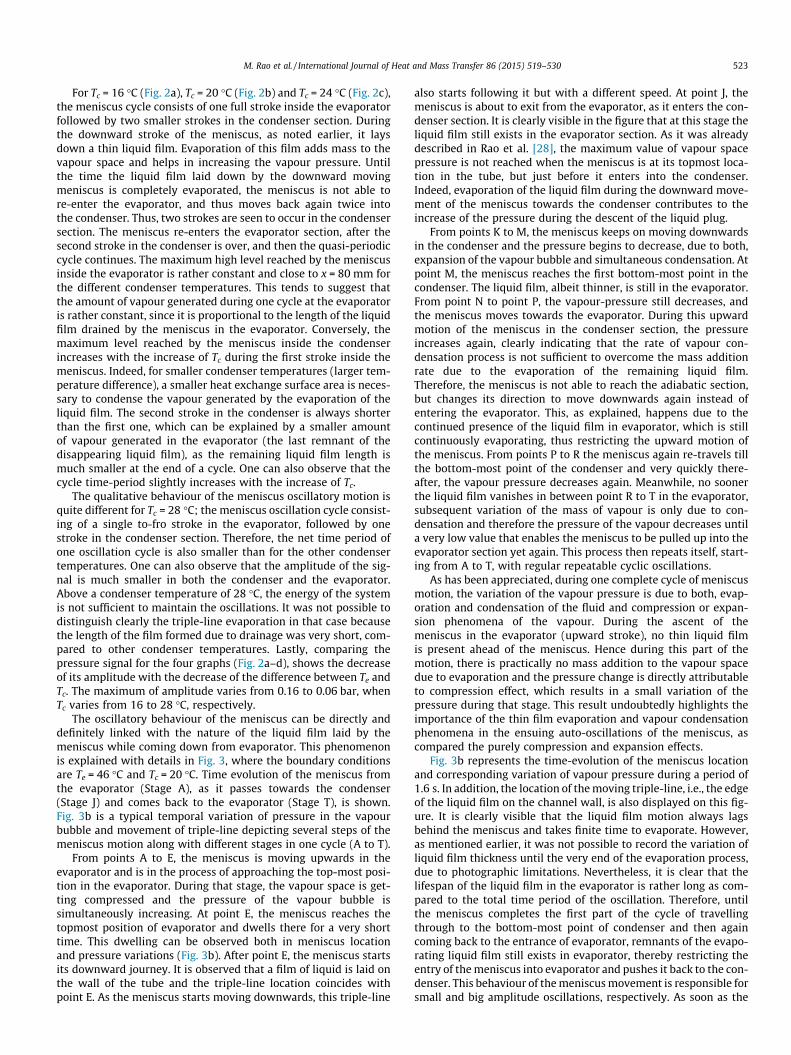
The oscillatory behaviour of the meniscus can be directly anddefinitely linked with the nature of the liquid film laid by themeniscus while coming down from evaporator. This phenomenonis explained with details in Fig. 3, where the boundary conditionsare Te = 46 �C and Tc = 20 �C. Time evolution of the meniscus fromthe evaporator (Stage A), as it passes towards the condenser(Stage J) and comes back to the evaporator (Stage T), is shown.Fig. 3b is a typical temporal variation of pressure in the vapourbubble and movement of triple-line depicting several steps of themeniscus motion along with different stages in one cycle (A to T).
From points A to E, the meniscus is moving upwards in theevaporator and is in the process of approaching the top-most posi-tion in the evaporator. During that stage, the vapour space is get-ting compressed and the pressure of the vapour bubble issimultaneously increasing. At point E, the meniscus reaches thetopmost position of evaporator and dwells there for a very shorttime. This dwelling can be observed both in meniscus locationand pressure variations (Fig. 3b). After point E, the meniscus startsits downward journey. It is observed that a film of liquid is laid onthe wall of the tube and the triple-line location coincides withpoint E. As the meniscus starts moving downwards, this triple-line
also starts following it but with a different speed. At point J, themeniscus is about to exit from the evaporator, as it enters the con-denser section. It is clearly visible in the figure that at this stage theliquid film still exists in the evaporator section. As it was alreadydescribed in Rao et al. [28], the maximum value of vapour spacepressure is not reached when the meniscus is at its topmost loca-tion in the tube, but just before it enters into the condenser.Indeed, evaporation of the liquid film during the downward move-ment of the meniscus towards the condenser contributes to theincrease of the pressure during the descent of the liquid plug.
From points K to M, the meniscus keeps on moving downwardsin the condenser and the pressure begins to decrease, due to both,expansion of the vapour bubble and simultaneous condensation. Atpoint M, the meniscus reaches the first bottom-most point in thecondenser. The liquid film, albeit thinner, is still in the evaporator.From point N to point P, the vapour-pressure still decreases, andthe meniscus moves towards the evaporator. During this upwardmotion of the meniscus in the condenser section, the pressureincreases again, clearly indicating that the rate of vapour con-densation process is not sufficient to overcome the mass additionrate due to the evaporation of the remaining liquid film.Therefore, the meniscus is not able to reach the adiabatic section,but changes its direction to move downwards again instead ofentering the evaporator. This, as explained, happens due to thecontinued presence of the liquid film in evaporator, which is stillcontinuously evaporating, thus restricting the upward motion ofthe meniscus. From points P to R the meniscus again re-travels tillthe bottom-most point of the condenser and very quickly there-after, the vapour pressure decreases again. Meanwhile, no soonerthe liquid film vanishes in between point R to T in the evaporator,subsequent variation of the mass of vapour is only due to con-densation and therefore the pressure of the vapour decreases untila very low value that enables the meniscus to be pulled up into theevaporator section yet again. This process then repeats itself, start-ing from A to T, with regular repeatable cyclic oscillations.
As has been appreciated, during one complete cycle of meniscusmotion, the variation of the vapour pressure is due to both, evap-oration and condensation of the fluid and compression or expan-sion phenomena of the vapour. During the ascent of themeniscus in the evaporator (upward stroke), no thin liquid filmis present ahead of the meniscus. Hence during this part of themotion, there is practically no mass addition to the vapour spacedue to evaporation and the pressure change is directly attributableto compression effect, which results in a small variation of thepressure during that stage. This result undoubtedly highlights theimportance of the thin film evaporation and vapour condensationphenomena in the ensuing auto-oscillations of the meniscus, ascompared the purely compression and expansion effects.
Fig. 3b represents the time-evolution of the meniscus locationand corresponding variation of vapour pressure during a period of1.6 s. In addition, the location of the moving triple-line, i.e., the edgeof the liquid film on the channel wall, is also displayed on this fig-ure. It is clearly visible that the liquid film motion always lagsbehind the meniscus and takes finite time to evaporate. However,as mentioned earlier, it was not possible to record the variation ofliquid film thickness until the very end of the evaporation process,due to photographic limitations. Nevertheless, it is clear that thelifespan of the liquid film in the evaporator is rather long as com-pared to the total time period of the oscillation. Therefore, untilthe meniscus completes the first part of the cycle of travellingthrough to the bottom-most point of condenser and then againcoming back to the entrance of evaporator, remnants of the evapo-rating liquid film still exists in evaporator, thereby restricting theentry of the meniscus into evaporator and pushes it back to the con-denser. This behaviour of the meniscus movement is responsible forsmall and big amplitude oscillations, respectively. As soon as the
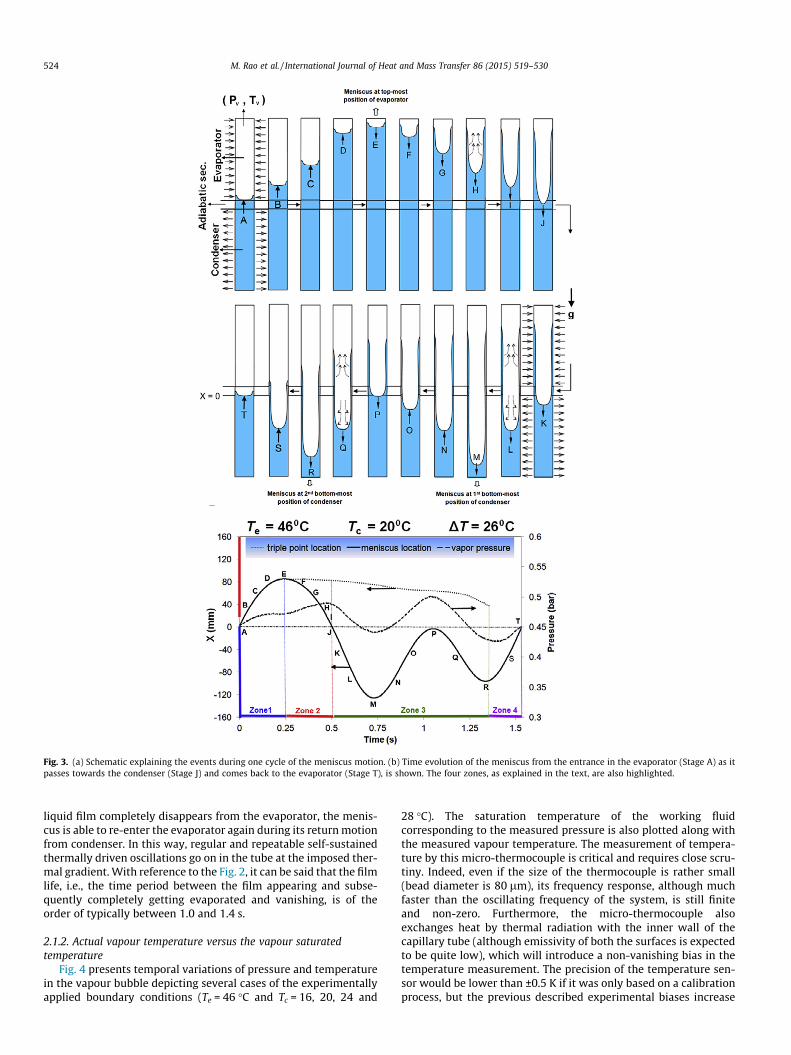
Fig. 3. (a) Schematic explaining the events during one cycle of the meniscus motion. (b) Time evolution of the meniscus from the entrance in the evaporator (Stage A) as itpasses towards the condenser (Stage J) and comes back to the evaporator (Stage T), is shown. The four zones, as explained in the text, are also highlighted.
524 M. Rao et al. / International Journal of Heat and Mass Transfer 86 (2015) 519–530
liquid film completely disappears from the evaporator, the menis-cus is able to re-enter the evaporator again during its return motionfrom condenser. In this way, regular and repeatable self-sustainedthermally driven oscillations go on in the tube at the imposed ther-mal gradient. With reference to the Fig. 2, it can be said that the filmlife, i.e., the time period between the film appearing and subse-quently completely getting evaporated and vanishing, is of theorder of typically between 1.0 and 1.4 s.
2.1.2. Actual vapour temperature versus the vapour saturatedtemperature
Fig. 4 presents temporal variations of pressure and temperaturein the vapour bubble depicting several cases of the experimentallyapplied boundary conditions (Te = 46 �C and Tc = 16, 20, 24 and
28 �C). The saturation temperature of the working fluidcorresponding to the measured pressure is also plotted along withthe measured vapour temperature. The measurement of tempera-ture by this micro-thermocouple is critical and requires close scru-tiny. Indeed, even if the size of the thermocouple is rather small(bead diameter is 80 lm), its frequency response, although muchfaster than the oscillating frequency of the system, is still finiteand non-zero. Furthermore, the micro-thermocouple alsoexchanges heat by thermal radiation with the inner wall of thecapillary tube (although emissivity of both the surfaces is expectedto be quite low), which will introduce a non-vanishing bias in thetemperature measurement. The precision of the temperature sen-sor would be lower than ±0.5 K if it was only based on a calibrationprocess, but the previous described experimental biases increase
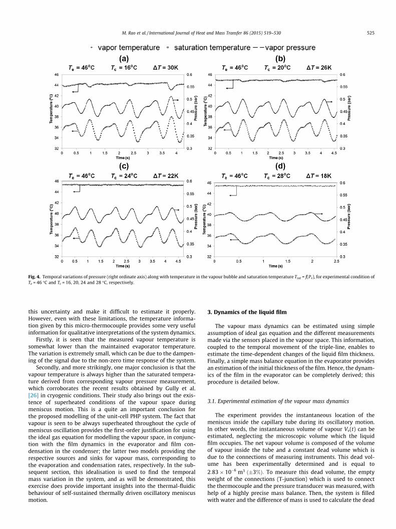
Fig. 4. Temporal variations of pressure (right ordinate axis) along with temperature in the vapour bubble and saturation temperature Tsat = f(Pv), for experimental condition ofTe = 46 �C and Tc = 16, 20, 24 and 28 �C, respectively.
M. Rao et al. / International Journal of Heat and Mass Transfer 86 (2015) 519–530 525
this uncertainty and make it difficult to estimate it properly.However, even with these limitations, the temperature informa-tion given by this micro-thermocouple provides some very usefulinformation for qualitative interpretations of the system dynamics.
Firstly, it is seen that the measured vapour temperature issomewhat lower than the maintained evaporator temperature.The variation is extremely small, which can be due to the dampen-ing of the signal due to the non-zero time response of the system.
Secondly, and more strikingly, one major conclusion is that thevapour temperature is always higher than the saturated tempera-ture derived from corresponding vapour pressure measurement,which corroborates the recent results obtained by Gully et al.[26] in cryogenic conditions. Their study also brings out the exis-tence of superheated conditions of the vapour space duringmeniscus motion. This is a quite an important conclusion forthe proposed modelling of the unit-cell PHP system. The fact thatvapour is seen to be always superheated throughout the cycle ofmeniscus oscillation provides the first-order justification for usingthe ideal gas equation for modelling the vapour space, in conjunc-tion with the film dynamics in the evaporator and film con-densation in the condenser; the latter two models providing therespective sources and sinks for vapour mass, corresponding tothe evaporation and condensation rates, respectively. In the sub-sequent section, this idealisation is used to find the temporalmass variation in the system, and as will be demonstrated, thisexercise does provide important insights into the thermal-fluidicbehaviour of self-sustained thermally driven oscillatory meniscusmotion.
3. Dynamics of the liquid film
The vapour mass dynamics can be estimated using simpleassumption of ideal gas equation and the different measurementsmade via the sensors placed in the vapour space. This information,coupled to the temporal movement of the triple-line, enables toestimate the time-dependent changes of the liquid film thickness.Finally, a simple mass balance equation in the evaporator providesan estimation of the initial thickness of the film. Hence, the dynam-ics of the film in the evaporator can be completely derived; thisprocedure is detailed below.
3.1. Experimental estimation of the vapour mass dynamics
The experiment provides the instantaneous location of themeniscus inside the capillary tube during its oscillatory motion.In other words, the instantaneous volume of vapour Vv(t) can beestimated, neglecting the microscopic volume which the liquidfilm occupies. The net vapour volume is composed of the volumeof vapour inside the tube and a constant dead volume which isdue to the connections of measuring instruments. This dead vol-ume has been experimentally determined and is equal to2:83� 10�6 m3 ð�3%Þ: To measure this dead volume, the emptyweight of the connections (T-junction) which is used to connectthe thermocouple and the pressure transducer was measured, withhelp of a highly precise mass balance. Then, the system is filledwith water and the difference of mass is used to calculate the dead
526 M. Rao et al. / International Journal of Heat and Mass Transfer 86 (2015) 519–530
volume inside the system. This process is repeated several times tominimize the error.
The instantaneous pressure of the vapour plug Pv(t) is alsoknown from the measurements. Furthermore, it was shown inthe last section that the vapour temperature Tv(t) is always abovethe saturation temperature. Therefore, ideal gas equation can beinvoked to obtain the instantaneous mass of vapour mv(t) insidethe system:
mvðtÞ ¼PvðtÞ � VvðtÞ
�R� TvðtÞ�M ð1Þ
where �R is the universal gas constant and M ¼ 338 g=mol, themolecular weight of FC72.
Fig. 5 shows the temporal variations of meniscus location andtriple-line locations, respectively, along with the mass of vapourcalculated using ideal gas, Eq. (1), depicting several cases of theapplied boundary conditions (Te = 46 �C and Tc = 16, 20 and24 �C). Vapour mass variation inside the system is a combinedeffect of evaporation and condensation, respectively, which maybe occurring simultaneously. Therefore, any combination of evap-oration and condensation rates can produce this variation ofvapour mass. One has to develop a heat transfer model to extractthese parameters from the experimental data. It is also observedin Fig. 5d that even a ±10 �C variation in vapour temperature mea-surement affects only ±3% of instantaneous vapour mass calcula-tions. Therefore, even if the temperature measurement by the
Fig. 5. Temporal variations of location of meniscus (left ordinate axis, solid line), triple-linusing ideal gas equation (Ref. Fig. 1) and Eq. (1) (at Te = 46 �C and (a) Tc = 16 �C, (b) Tc =vapour temperature on the mass of vapour).
micro-thermocouple is not highly accurate, the validity of theestimation of the vapour mass certainly remains rather reasonable.
To analyse the experimental data, the oscillation cycle isdivided into four different zones that are earlier depicted inFig. 3b. In Zone #1, between points A and E, there is no liquid filmon the tube wall as the meniscus is moving up in the evaporator.Simultaneously, we observe a decrease of the mass of vapour thatcan be explained by condensation on the meniscus due to com-pression of the vapour. From point E to J, referred to as Zone #2,the meniscus is moving down in the evaporator tube section andis laying a liquid film on the evaporator wall. Hence, the lengthof the liquid film in the evaporator increases due to the downwardmovement of the meniscus and decreases due to simultaneousevaporation. Zone #3 commences from Point J onwards and termi-nates when the liquid film cannot be observed anymore. In thisoperational zone, it is assumed that the length of the liquid filmin the evaporator is only decreasing due to its evaporation at thetriple-line. The last zone is Zone #4, where the vanishing liquidfilm cannot be observed due to the lack of camera resolution.Nevertheless, a few monolayers of liquid film remnants may stillremain which will subsequently evaporate. While condensationof vapour occurs primarily on the liquid film in the condenser, itcan also be observed on the liquid film in the evaporator, as hasalso been shown by Rao et al. [28]. Indeed, the temperature ofthe liquid plug coming from the condenser region and enteringinto the evaporator section in the upward stroke (A to E) is muchlower than the vapour temperature already present there. Since
e (left ordinate axis, dotted line) and mass of vapour (right ordinate axis) calculated20 �C, (c) Tc = 24 �C, and (d) Tc = 24 �C, respectively, showing the sensitivity of the
M. Rao et al. / International Journal of Heat and Mass Transfer 86 (2015) 519–530 527
diffusion time scales in the bulk liquid region are large, as clearlyindicated by Rao et al. [28], the temperature of the liquid film thatis laid by the meniscus during its journey towards the condenser ismuch lower than the adjoining vapour mass, which leads to con-densation on the film surface. After a while, the liquid film tem-perature increases due to heat conduction from the wall. Then,evaporation of the liquid film begins at the liquid vapour interface.All these physical mechanisms have to be introduced in the heatand mass transfer model to understand the dynamics of the liquidfilm. The mass transfer interactions due to the liquid film at theevaporator section are complex and its understanding is the keyto this analysis.
3.2. Modelling vapour mass dynamics
The variation of vapour mass is estimated from the raw experi-mental data, as per Fig. 5. This variation is due to four differentcontributions:
� Condensation of vapour on the liquid film portion in the con-denser section,� Condensation of vapour on the meniscus formed between the
vapour plug and the liquid slug,� Evaporation at the triple-line formed between the liquid film,
the wall and the vapour phase,� Mass transfer (evaporation or condensation) between the liquid
film and the vapour in the evaporator section.
The condensation rate due to the first two terms can beobtained by the energy equation:
_mcond ¼1
hlvhc;lf pDiLc;lf ðtÞ½TsatðtÞ � Tc� þ Kcond½TsatðtÞ � Tc�� �
ð2Þ
where, Kcond is the overall thermal conductance of condensationoccurring on the meniscus and hc,lf, the condensation heat transfercoefficient between the vapour and the condenser; the justificationfor taking these two terms separately and their relative importancewill be clear in the subsequent analysis which follows. In Eq. (2), Tsat
is the saturation temperature corresponding to the pressure of thevapour, which will apply at the interface and Tc the temperatureof the heat sink, which is controlled by the thermostatic bath. Lc,lf
(t) is the instantaneous liquid film length in the condenser. In orderto simplify the model, we assume that the liquid–vapour interfaceat the condenser is hemispherical with diameter Di. In reality, theinterface area is somewhat smaller due to the thickness of the filmon the wall, but based on present experimental evidence too, wecan safely assume that this thickness is negligible as compared tothe tube diameter.
The overall thermal conductance of condensation, Kcond can beestimated by comparison between the mass of vapour (Eq. (1)) cal-culated from the experimental data during the upward motion ofthe meniscus inside the evaporator (Zone #1) and Eq. (2). Indeed,in Zone #1, the vapour mass variation is only due to this term(and therefore, term #1 in Eq. (2) vanishes in Zone #1 from A toE). The heat transfer coefficient for condensation in the condensersection, hc,lf is linked to the thickness of the liquid film and its orderof magnitude can be estimated as �kl/d0, where kl is the thermalconductivity of the liquid and d0 is the initial thickness of the filmwhich is a key parameter for discerning the dynamics of the film[24–26,28]. We assume that the variation of the film thicknessdue to the condensation of the vapour in the condenser is smallenough to be neglected; also, the temperature of the wall at thecondenser is constant and equal to Tc. The temperature of the liq-uid plug inside the capillary tube is also taken to be very close tothe condenser temperature.
The mass transfer due to the liquid film in the evaporator ismore complex and cannot be obtained by the same approach.Two mechanisms have to be taken into account, i.e., the evap-oration at the triple-line and the mass transfer at the liquid–vapourinterface of the thin film. The temperature of the inner wall of theevaporator cannot be considered as constant, equal to the heatsource temperature in this experiment. Indeed, during one cycle,the upper part of the inner tube is always in contact with thevapour plug while the bottom part of the tube is in contact eitherwith vapour or with the liquid film, or with the liquid plug.Furthermore, as the material of the tube is glass, it has a small ther-mal diffusivity and therefore its time scale is higher than the oscil-lation period [28]. For all these compelling reasons, the innertemperature of the wall is an unknown function of time and space.Therefore, the modelling of the dynamics of the film cannot be esti-mated using an evaporating heat transfer coefficient as was possi-ble in the condenser section.
The thickness of the film in the evaporator is varying from aconstant value d0 – when the meniscus begins its journey towardsthe condenser – to zero at the end of the cycle. This variation is dueto two different phenomena: the evaporation at the triple-line andthe mass transfer at the liquid–vapour interface of the film. Let usassume that d(t) is not a function of the location inside the evap-orator, but only a function of time. This hypothesis is reasonableas the temporal variation of the location of the triple-line is muchslower than the temporal variation of the meniscus location.Therefore, the mass transfer rate between the liquid film and thevapour plug can be expressed as:
_mlf ¼ �qlpDi dðtÞdxlf ðtÞdt
þ Le;lf ðtÞddðtÞ
dt
� �ð3Þ
where, xlf(t) is the location of the triple-line and Le,lf(t) is the lengthof the liquid film in the evaporator, which are outputs of the experi-ments. The minus sign in Eq. (3) is due to the negative sign of thederivative of xlf and d during evaporation.The mass variation ofthe vapour can be expressed as:
_mv ¼dmv
dt¼ _mlf � _mcond ð4Þ
The mass of vapour is known at each time (Eq. (1)), therefore thevariation of the film thickness can be estimated by:
ddðtÞdt¼ � 1
Le;lf ðtÞ_mv þ _mcond
qlpDiþ dðtÞdxlf ðtÞ
dt
� �ð5Þ
Finally, the equation of d(t) can be written as:
dðtÞ ¼ d0 þddðtÞ
dtDt ð6Þ
This model enables to estimate the complete dynamics of theliquid film by comparison with the experimental data. The initialthickness d0 can be calculated by integrating the mass balanceequation for the liquid film over a complete period of time:Z
_mlf ¼Z
_mv þ _mcond ¼ qlpDid0Llf ;max ð7Þ
One can note that even if one part of the triple-line is notrecorded by the high speed camera, Eq. (7) enables to estimatethe initial value of d.
3.3. Comparison of model predictions with experiments
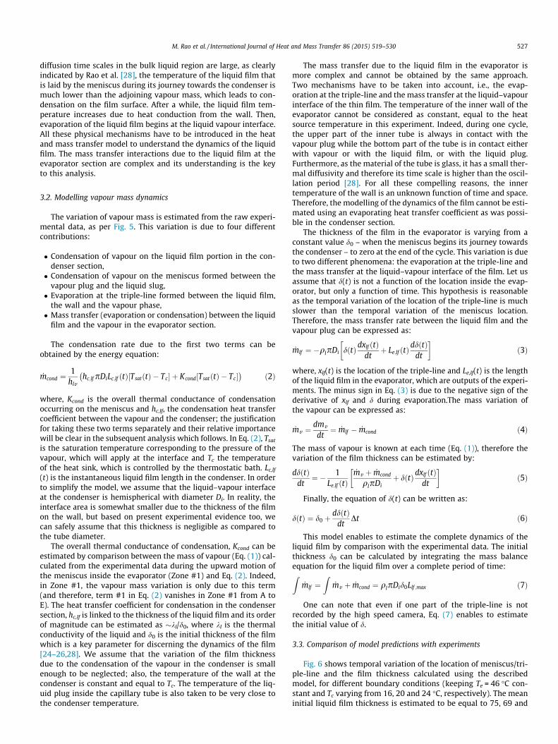
Fig. 6 shows temporal variation of the location of meniscus/tri-ple-line and the film thickness calculated using the describedmodel, for different boundary conditions (keeping Te = 46 �C con-stant and Tc varying from 16, 20 and 24 �C, respectively). The meaninitial liquid film thickness is estimated to be equal to 75, 69 and
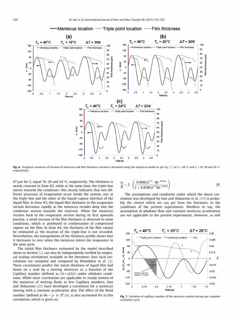
Fig. 6. Temporal variations of location of meniscus and film thickness variation calculated using the analytical model as per Eq. (7) (at Te = 46 �C and Tc = 16, 20 and 24 �C,respectively).
Fig. 7. Variation of capillary number of the meniscus motion during one completeoscillation cycle.
528 M. Rao et al. / International Journal of Heat and Mass Transfer 86 (2015) 519–530
67 lm for Tc equal 16, 20 and 24 �C, respectively. The thickness isnearly constant in Zone #2, while at the same time, the triple-linemoves towards the condenser; this clearly indicates that two dif-ferent processes of evaporation occur inside the system, one atthe triple-line and the other at the liquid–vapour interface of theliquid film. In Zone #3, the liquid film thickness in the evaporatorsection decreases rapidly as the meniscus recedes deep into thecondenser section towards the reservoir. When the meniscusreaches back to the evaporator section during its first upwardsjourney, a small increase of the film thickness is observed in someconditions, which is attributed to condensation of compressedvapour on the film. In Zone #4, the thickness of the film cannotbe estimated as the location of the triple-line is not recorded.Nevertheless, the extrapolation of the thickness profile shows thatit decreases to zero when the meniscus enters the evaporator inthe next cycle.
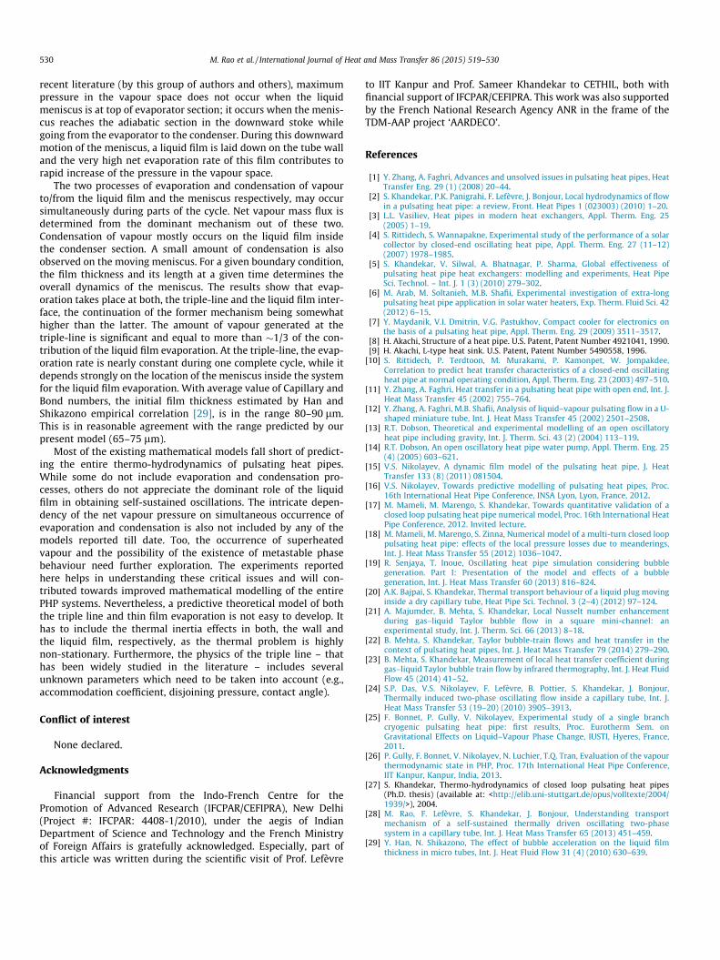
The initial film thickness estimated by the model describedabove in Section 3.2 can also be independently verified by empiri-cal scaling correlations available in the literature; four such cor-relations are compiled and compared by Khandekar et al. [2].These correlations predict the initial thickness of liquid film laiddown on a wall by a moving meniscus as a function of theCapillary number (defined as Ca = lU/r) under adiabatic condi-tions. While most correlations are applicable to steady motion ofthe meniscus of wetting fluids at low Capillary numbers, Hanand Shikazono [29] have developed a correlation for a meniscusmoving with a constant acceleration also. The effect of the Bondnumber (defined as Bo ¼ q � a � D2=r), is also accounted for in thiscorrelation, which is given as:
d0
R¼ 2 � 0:968Ca2=3 � Bo�0:414
1þ 4:838Ca2=3Bo�0:414
!ð8Þ
The assumptions and conditions under which the above cor-relation was developed by Han and Shikazono et al. [29] is proba-bly the closest which we can get from the literature, to theconditions of the present experiments. Needless to say, theassumption of adiabatic flow and constant meniscus accelerationare not applicable to the present experiments. However, as will
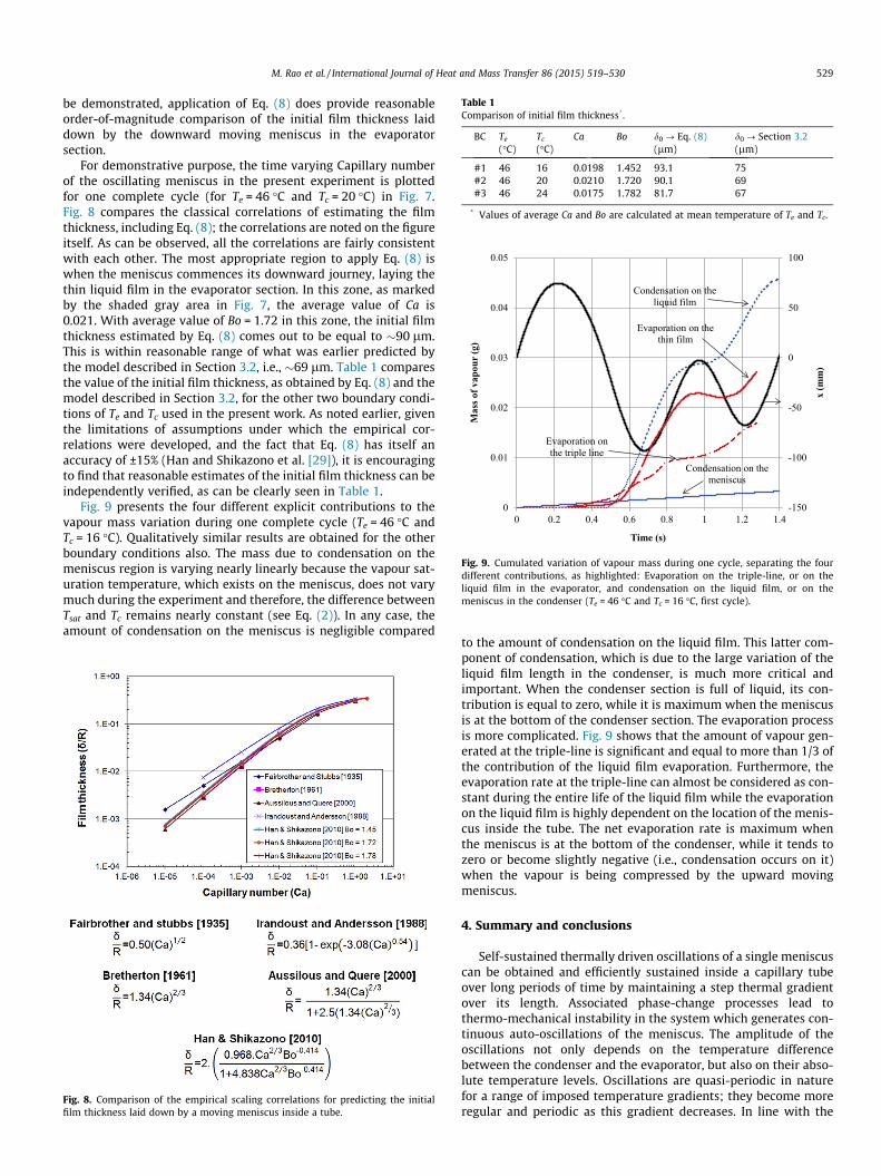
Table 1Comparison of initial film thickness*.
BC Te
(�C)Tc
(�C)Ca Bo d0 ? Eq. (8)
(lm)d0 ? Section 3.2(lm)
#1 46 16 0.0198 1.452 93.1 75#2 46 20 0.0210 1.720 90.1 69#3 46 24 0.0175 1.782 81.7 67
* Values of average Ca and Bo are calculated at mean temperature of Te and Tc.
-150
-100
-50
0
50
100
0
0.01
0.02
0.03
0.04
0.05
0 0.2 0.4 0.6 0.8 1 1.2 1.4
x (m
m)
Mas
s of v
apou
r (g
)
Time (s)
Condensation on the liquid film
Condensation on the meniscus
Evaporation on the triple line
Evaporation on the thin film
Fig. 9. Cumulated variation of vapour mass during one cycle, separating the fourdifferent contributions, as highlighted: Evaporation on the triple-line, or on theliquid film in the evaporator, and condensation on the liquid film, or on themeniscus in the condenser (Te = 46 �C and Tc = 16 �C, first cycle).
M. Rao et al. / International Journal of Heat and Mass Transfer 86 (2015) 519–530 529
be demonstrated, application of Eq. (8) does provide reasonableorder-of-magnitude comparison of the initial film thickness laiddown by the downward moving meniscus in the evaporatorsection.
For demonstrative purpose, the time varying Capillary numberof the oscillating meniscus in the present experiment is plottedfor one complete cycle (for Te = 46 �C and Tc = 20 �C) in Fig. 7.Fig. 8 compares the classical correlations of estimating the filmthickness, including Eq. (8); the correlations are noted on the figureitself. As can be observed, all the correlations are fairly consistentwith each other. The most appropriate region to apply Eq. (8) iswhen the meniscus commences its downward journey, laying thethin liquid film in the evaporator section. In this zone, as markedby the shaded gray area in Fig. 7, the average value of Ca is0.021. With average value of Bo = 1.72 in this zone, the initial filmthickness estimated by Eq. (8) comes out to be equal to �90 lm.This is within reasonable range of what was earlier predicted bythe model described in Section 3.2, i.e., �69 lm. Table 1 comparesthe value of the initial film thickness, as obtained by Eq. (8) and themodel described in Section 3.2, for the other two boundary condi-tions of Te and Tc used in the present work. As noted earlier, giventhe limitations of assumptions under which the empirical cor-relations were developed, and the fact that Eq. (8) has itself anaccuracy of ±15% (Han and Shikazono et al. [29]), it is encouragingto find that reasonable estimates of the initial film thickness can beindependently verified, as can be clearly seen in Table 1.
Fig. 9 presents the four different explicit contributions to thevapour mass variation during one complete cycle (Te = 46 �C andTc = 16 �C). Qualitatively similar results are obtained for the otherboundary conditions also. The mass due to condensation on themeniscus region is varying nearly linearly because the vapour sat-uration temperature, which exists on the meniscus, does not varymuch during the experiment and therefore, the difference betweenTsat and Tc remains nearly constant (see Eq. (2)). In any case, theamount of condensation on the meniscus is negligible compared
Fig. 8. Comparison of the empirical scaling correlations for predicting the initialfilm thickness laid down by a moving meniscus inside a tube.
to the amount of condensation on the liquid film. This latter com-ponent of condensation, which is due to the large variation of theliquid film length in the condenser, is much more critical andimportant. When the condenser section is full of liquid, its con-tribution is equal to zero, while it is maximum when the meniscusis at the bottom of the condenser section. The evaporation processis more complicated. Fig. 9 shows that the amount of vapour gen-erated at the triple-line is significant and equal to more than 1/3 ofthe contribution of the liquid film evaporation. Furthermore, theevaporation rate at the triple-line can almost be considered as con-stant during the entire life of the liquid film while the evaporationon the liquid film is highly dependent on the location of the menis-cus inside the tube. The net evaporation rate is maximum whenthe meniscus is at the bottom of the condenser, while it tends tozero or become slightly negative (i.e., condensation occurs on it)when the vapour is being compressed by the upward movingmeniscus.
4. Summary and conclusions
Self-sustained thermally driven oscillations of a single meniscuscan be obtained and efficiently sustained inside a capillary tubeover long periods of time by maintaining a step thermal gradientover its length. Associated phase-change processes lead tothermo-mechanical instability in the system which generates con-tinuous auto-oscillations of the meniscus. The amplitude of theoscillations not only depends on the temperature differencebetween the condenser and the evaporator, but also on their abso-lute temperature levels. Oscillations are quasi-periodic in naturefor a range of imposed temperature gradients; they become moreregular and periodic as this gradient decreases. In line with the
530 M. Rao et al. / International Journal of Heat and Mass Transfer 86 (2015) 519–530
recent literature (by this group of authors and others), maximumpressure in the vapour space does not occur when the liquidmeniscus is at top of evaporator section; it occurs when the menis-cus reaches the adiabatic section in the downward stoke whilegoing from the evaporator to the condenser. During this downwardmotion of the meniscus, a liquid film is laid down on the tube walland the very high net evaporation rate of this film contributes torapid increase of the pressure in the vapour space.
The two processes of evaporation and condensation of vapourto/from the liquid film and the meniscus respectively, may occursimultaneously during parts of the cycle. Net vapour mass flux isdetermined from the dominant mechanism out of these two.Condensation of vapour mostly occurs on the liquid film insidethe condenser section. A small amount of condensation is alsoobserved on the moving meniscus. For a given boundary condition,the film thickness and its length at a given time determines theoverall dynamics of the meniscus. The results show that evap-oration takes place at both, the triple-line and the liquid film inter-face, the continuation of the former mechanism being somewhathigher than the latter. The amount of vapour generated at thetriple-line is significant and equal to more than �1/3 of the con-tribution of the liquid film evaporation. At the triple-line, the evap-oration rate is nearly constant during one complete cycle, while itdepends strongly on the location of the meniscus inside the systemfor the liquid film evaporation. With average value of Capillary andBond numbers, the initial film thickness estimated by Han andShikazono empirical correlation [29], is in the range 80–90 lm.This is in reasonable agreement with the range predicted by ourpresent model (65–75 lm).
Most of the existing mathematical models fall short of predict-ing the entire thermo-hydrodynamics of pulsating heat pipes.While some do not include evaporation and condensation pro-cesses, others do not appreciate the dominant role of the liquidfilm in obtaining self-sustained oscillations. The intricate depen-dency of the net vapour pressure on simultaneous occurrence ofevaporation and condensation is also not included by any of themodels reported till date. Too, the occurrence of superheatedvapour and the possibility of the existence of metastable phasebehaviour need further exploration. The experiments reportedhere helps in understanding these critical issues and will con-tributed towards improved mathematical modelling of the entirePHP systems. Nevertheless, a predictive theoretical model of boththe triple line and thin film evaporation is not easy to develop. Ithas to include the thermal inertia effects in both, the wall andthe liquid film, respectively, as the thermal problem is highlynon-stationary. Furthermore, the physics of the triple line – thathas been widely studied in the literature – includes severalunknown parameters which need to be taken into account (e.g.,accommodation coefficient, disjoining pressure, contact angle).
Conflict of interest
None declared.
Acknowledgments
Financial support from the Indo-French Centre for thePromotion of Advanced Research (IFCPAR/CEFIPRA), New Delhi(Project #: IFCPAR: 4408-1/2010), under the aegis of IndianDepartment of Science and Technology and the French Ministryof Foreign Affairs is gratefully acknowledged. Especially, part ofthis article was written during the scientific visit of Prof. Lefèvre
to IIT Kanpur and Prof. Sameer Khandekar to CETHIL, both withfinancial support of IFCPAR/CEFIPRA. This work was also supportedby the French National Research Agency ANR in the frame of theTDM-AAP project ‘AARDECO’.
References
[1] Y. Zhang, A. Faghri, Advances and unsolved issues in pulsating heat pipes, HeatTransfer Eng. 29 (1) (2008) 20–44.
[2] S. Khandekar, P.K. Panigrahi, F. Lefèvre, J. Bonjour, Local hydrodynamics of flowin a pulsating heat pipe: a review, Front. Heat Pipes 1 (023003) (2010) 1–20.
[3] L.L. Vasiliev, Heat pipes in modern heat exchangers, Appl. Therm. Eng. 25(2005) 1–19.
[4] S. Rittidech, S. Wannapakne, Experimental study of the performance of a solarcollector by closed-end oscillating heat pipe, Appl. Therm. Eng. 27 (11–12)(2007) 1978–1985.
[5] S. Khandekar, V. Silwal, A. Bhatnagar, P. Sharma, Global effectiveness ofpulsating heat pipe heat exchangers: modelling and experiments, Heat PipeSci. Technol. – Int. J. 1 (3) (2010) 279–302.
[6] M. Arab, M. Soltanieh, M.B. Shafii, Experimental investigation of extra-longpulsating heat pipe application in solar water heaters, Exp. Therm. Fluid Sci. 42(2012) 6–15.
[7] Y. Maydanik, V.I. Dmitrin, V.G. Pastukhov, Compact cooler for electronics onthe basis of a pulsating heat pipe, Appl. Therm. Eng. 29 (2009) 3511–3517.
[8] H. Akachi, Structure of a heat pipe. U.S. Patent, Patent Number 4921041, 1990.[9] H. Akachi, L-type heat sink. U.S. Patent, Patent Number 5490558, 1996.
[10] S. Rittidech, P. Terdtoon, M. Murakami, P. Kamonpet, W. Jompakdee,Correlation to predict heat transfer characteristics of a closed-end oscillatingheat pipe at normal operating condition, Appl. Therm. Eng. 23 (2003) 497–510.
[11] Y. Zhang, A. Faghri, Heat transfer in a pulsating heat pipe with open end, Int. J.Heat Mass Transfer 45 (2002) 755–764.
[12] Y. Zhang, A. Faghri, M.B. Shafii, Analysis of liquid–vapour pulsating flow in a U-shaped miniature tube, Int. J. Heat Mass Transfer 45 (2002) 2501–2508.
[13] R.T. Dobson, Theoretical and experimental modelling of an open oscillatoryheat pipe including gravity, Int. J. Therm. Sci. 43 (2) (2004) 113–119.
[14] R.T. Dobson, An open oscillatory heat pipe water pump, Appl. Therm. Eng. 25(4) (2005) 603–621.
[15] V.S. Nikolayev, A dynamic film model of the pulsating heat pipe, J. HeatTransfer 133 (8) (2011) 081504.
[16] V.S. Nikolayev, Towards predictive modelling of pulsating heat pipes, Proc.16th International Heat Pipe Conference, INSA Lyon, Lyon, France, 2012.
[17] M. Mameli, M. Marengo, S. Khandekar, Towards quantitative validation of aclosed loop pulsating heat pipe numerical model, Proc. 16th International HeatPipe Conference, 2012. Invited lecture.
[18] M. Mameli, M. Marengo, S. Zinna, Numerical model of a multi-turn closed looppulsating heat pipe: effects of the local pressure losses due to meanderings,Int. J. Heat Mass Transfer 55 (2012) 1036–1047.
[19] R. Senjaya, T. Inoue, Oscillating heat pipe simulation considering bubblegeneration. Part I: Presentation of the model and effects of a bubblegeneration, Int. J. Heat Mass Transfer 60 (2013) 816–824.
[20] A.K. Bajpai, S. Khandekar, Thermal transport behaviour of a liquid plug movinginside a dry capillary tube, Heat Pipe Sci. Technol. 3 (2–4) (2012) 97–124.
[21] A. Majumder, B. Mehta, S. Khandekar, Local Nusselt number enhancementduring gas–liquid Taylor bubble flow in a square mini-channel: anexperimental study, Int. J. Therm. Sci. 66 (2013) 8–18.
[22] B. Mehta, S. Khandekar, Taylor bubble-train flows and heat transfer in thecontext of pulsating heat pipes, Int. J. Heat Mass Transfer 79 (2014) 279–290.
[23] B. Mehta, S. Khandekar, Measurement of local heat transfer coefficient duringgas–liquid Taylor bubble train flow by infrared thermography, Int. J. Heat FluidFlow 45 (2014) 41–52.
[24] S.P. Das, V.S. Nikolayev, F. Lefèvre, B. Pottier, S. Khandekar, J. Bonjour,Thermally induced two-phase oscillating flow inside a capillary tube, Int. J.Heat Mass Transfer 53 (19–20) (2010) 3905–3913.
[25] F. Bonnet, P. Gully, V. Nikolayev, Experimental study of a single branchcryogenic pulsating heat pipe: first results, Proc. Eurotherm Sem. onGravitational Effects on Liquid–Vapour Phase Change, IUSTI, Hyeres, France,2011.
[26] P. Gully, F. Bonnet, V. Nikolayev, N. Luchier, T.Q. Tran, Evaluation of the vapourthermodynamic state in PHP, Proc. 17th International Heat Pipe Conference,IIT Kanpur, Kanpur, India, 2013.
[27] S. Khandekar, Thermo-hydrodynamics of closed loop pulsating heat pipes(Ph.D. thesis) (available at: <http://elib.uni-stuttgart.de/opus/volltexte/2004/1939/>), 2004.
[28] M. Rao, F. Lefèvre, S. Khandekar, J. Bonjour, Understanding transportmechanism of a self-sustained thermally driven oscillating two-phasesystem in a capillary tube, Int. J. Heat Mass Transfer 65 (2013) 451–459.
[29] Y. Han, N. Shikazono, The effect of bubble acceleration on the liquid filmthickness in micro tubes, Int. J. Heat Fluid Flow 31 (4) (2010) 630–639.


![Author's personal copy - IITKhome.iitk.ac.in/~samkhan/Bio_data/publications/Khandekar_26.pdf · Author's personal copy Nusselt number under such conditions. Celata et al.[19] observed](https://img.pdfslide.us/doc/110x75/5ecb238ba62ad97ce66ac608/authors-personal-copy-samkhanbiodatapublicationskhandekar26pdf-authors.jpg)