Embed Size (px)
Citation preview

International Journal of Engineering Research and General Science Volume 3, Issue 3, May-June, 2015 ISSN 2091-2730
1565 www.ijergs.org
Design of Advanced Electromagnetic Emergency Braking System
Mr. Parag Satish Kulkarni.
B.E.A.M.I.E Student.
Department of Mechanical Engineering.
Maulana Mukhtar Ahmad Nadvi Technical Campus.
Savitribai Phule Pune University
Abstract: A brake is a device by means of which artificial frictional resistance is applied to a moving member, in order to retard or
stop the motion of a machine. In the process of performing this function, the brake absorbs either kinematic energy of moving member
or potential energy given up by objects lowered by hoists, elevators etc. An emergency brake is a backup braking system designed to
function even when there is total brake failure. It works through purely mechanical means, and is independent of the hydraulic system
which controls the brakes normally. In addition to being used in emergency situations, an emergency brake is also used as a parking
brake, to prevent the car from rolling away, should it slip into gear. Like all parts of the braking system, the emergency brake should
be checked regularly to ensure that it is in good working order.
Keywords: Frictional resistance, motion of machine, emergency brake, controls the brake, to prevent the car, braking system, working
order.
Introduction:
In cars, the hand brake (also known as the emergency brake, e-brake, park brake, slide stick or parking brake) is a supplementary
system that can be used if the vehicle's primary brake system (usually hydraulic brakes) has a failure. Automobile brakes usually
consist of a cable (usually adjustable for length) directly connected to the brake mechanism on one end and to some type of lever that
can be actuated by the driver on the other end [1]. The lever is traditionally and more commonly a hand-operated system (hence the
hand brake name), the most common configuration being a handle on the floor between the driver and front passenger, and less
commonly being a handle bar located on the lower portion of the dashboard.
However, the most common use for an automobile emergency brake is to keep the vehicle motionless when it is parked, thus
the alternative name, parking brake. Car emergency brakes have a ratchet locking mechanism that will keep them engaged until a
release button is pressed. On vehicles with automatic transmissions, this is usually used in concert with a parking pawl in the
transmission. Automotive safety experts recommend the use of both systems to immobilize a parked car, and the use of two systems is
required by law in some jurisdictions, yet many individuals use only the "Park" position on the automatic transmission and not the
parking brake. Also, manual transmission cars are recommended to be left in their lowest gear (usually either first or reverse) when
parked, especially when parked on an incline.
SCOPE OF THE WORK:
An emergency brake is a backup braking system designed to function even when there is total brake failure. It works through
purely mechanical means, and is independent of the hydraulic system which controls the brakes normally. In addition to being used in
emergency situations, an emergency brake is also used as a parking brake, to prevent the car from rolling away, should it slip into
gear. Like all parts of the braking system, the emergency brake should be checked regularly to ensure that it is in good working order.
To activate the emergency brake, the driver typically pulls up a lever or pushes a pedal in the front of the vehicle. Steel cables
attached to the emergency brake run to the rear brakes of the car, which are typically drum brakes [2]. When the cables are tightened,
International Journal of Engineering Research and General Science Volume 3, Issue 3, May-June, 2015 ISSN 2091-2730
1566 www.ijergs.org
they pull the brake shoes into contact with the drum of the brake, bringing the car to a stop. In the case of disc brakes, the brake cables
are attached to a small screw mechanism that pushes a piston into contact with the brake pads, forcing them to grip the brake rotor.
Typically the brake has a self-locking system, meaning that the driver must lower the lever or move the pedal to take the brake off. In
a car with a manual transmission, the emergency brake is used as a electromagnetic force on a regular basis, and some drivers may
also use it at stop signs. Because of the frequent use, the emergency brake is kept in good working order, although the cables may
need to be periodically tightened. In cars with automatic transmissions, however, some drivers do not set the emergency brake as a
parking brake. In addition to being unsafe, this also can lead to build up of rust and corrosion in the emergency brake cable, which
could result in cable failure in an emergency[2].
PROJECT FOCUS:
As in every vehicle brake is very important part to stop the vehicle there is no other device is use to stop the vehicle. For efficient
braking like in vehicle there is an technological development “power steering mechanism” using this mechanism one can drive the car
using single finger without any stress as concept we wants to develop “power brake” which is work on the principle of
“electromagnetic power” work on the principle of EMF electromotive force to braking to stop the vehicle.
LITERATURE SURVEY
BRAKE HISTORY
The modern automobile drum brake was invented in 1902 by Louis Renault. He used woven asbestos lining for the drum brakes
lining, as no alternative dissipated heat like the asbestos lining, though May batch has used a less sophisticated drum brake. In the first
drum brakes, levers and rods or cables operated the shoes mechanically. From the mid-1930s, oil pressure in a small wheel cylinder
and pistons (as in the picture) operated the brakes, though some vehicles continued with purely mechanical systems for decades. Some
designs have two wheel cylinders [1].
The shoes in drum brakes wear thinner, and brakes required regular adjustment until the introduction of self-adjusting drum
brakes in the 1950s. In the 1960s and 1970s, disk brakes gradually replaced drum brakes on the front wheels of cars. Now practically
all cars use disc brakes on the front wheels, and many use disc brakes on all wheels. However, drum brakes are still often used for
handbrakes, as it has proven very difficult to design a disc brake suitable for holding a parked car. Moreover, it is very easy to fit a
drum handbrake inside a disc brake so that one unit serves as both service brake and handbrake.
Early brake shoes contained asbestos. When working on brake systems of older cars, care must be taken not to inhale any dust
present in the brake assembly. The United States Federal Government began to regulate asbestos production, and brake manufacturers
had to switch to non-asbestos linings. Owners initially complained of poor braking with the replacements; however, technology
eventually advanced to compensate. A majority of daily-driven older vehicles have been fitted with asbestos-free linings. Many other
countries also limit the use of asbestos in brakes.
PARAMETER CONSIDER IN BRAKE DESIGN
1. TYPES OF FORCES CONSIDER IN BRAKE DESIGN:
A force is a push or pulls acting upon an object as a result of its interaction with another object. There are a variety of types of
forces. Previously in this lesson, a variety of force types were placed into two broad category headings on the basis of whether the
force resulted from the contact or non-contact of the two interacting objects [3].
The amount of friction force between two rubbing surfaces depends on the materials and their roughness. The amount of friction
is described by a number called the coefficient of friction. This speed car developed the Kinematic energy. The faster car it moves the

International Journal of Engineering Research and General Science Volume 3, Issue 3, May-June, 2015 ISSN 2091-2730
1567 www.ijergs.org
more energy it develops. This type of energy is called kinematic energy. When speed is doubled, four times the kinematic energy is
developed. That is, kinematic energy varies as the square of speed. To calculate kinematic energy of car, use the following,
Formula:
Kinematic energy = WCS2
/29.9 in kg-m
Where, WC = Weight of car in (kg)
S = Speed of car in meter per sec (mps)
2. CONVERTING ENERGY
Conventional braking systems function by converting a vehicle„s kinetic energy into heat energy via friction. When you press
down the brake pedal, the brake calipers clamp your brake pads against the brake rotor, and the friction between the two slows the
rotation of the brake rotor and the wheel attached to it. Combined with the traction your tires have on the road surface, your car‟s
momentum is slowed, and the resulting heat energy is left to dissipate into the air as the braking system cools doen.
2.1 REGENERATIVE BRAKING
Unlike traditional braking systems, far less energy is wasted during braking with a regenerative braking system. While traditional
braking is still required as a safety precaution as well as for lower speeds where regenerative yields begin to diminish, in the case of
the Toyota Prius, the bulk of braking duties are handled primarily by the electric motors mounted on the drive wheels. As the brake
pedal is depressed, these electric motors reverse their direction of rotation, and the resulting torque moving counter to the wheel‟s
motion helps to slow the car. When these motors reverse direction, they become in essence, a generator, and the surplus energy they
create is stored in a battery for later use [4]. This helps keep the battery packs in electric hybrids like the Prius fully charged without
having to resort to older, outdated methods such as physically plugging them into a power socket. This entire regenerative braking
system fits behind the wheels and resembles a large brake drum. These systems are not normally serviceable by the owner, and require
no extra attention.
2.2. KERS SYSTEMS
KERS stands for Kinetic Energy Recovery System. This system tends to come in an electrical and mechanical variety.
Electrical based systems tend to work similarly to those in the Prius, storing the energy normally lost in braking in a battery for use.
Mechanical systems work similarly, but store this energy in the form of a flywheel, which can spin up to 80,000 rpm. When additional
power is needed, this flywheel is connected to the rear wheels. Additional power can reach as high as 80hp from these systems,
usually for duration of up to a maximum of 6.67 seconds.
While regenerative braking systems are still just starting to become used in automotive street applications, they are showing a
large amount of promise in both passenger car and racing applications alike. With exception to additional weight, there are almost no
downsides to regenerative braking. With F1 KERS systems offering as much as an 80hp increase on demand, it is not unlikely to
expect to see these systems taking on a more performance-oriented role in future performance street cars.
A regenerative brake is an energy recovery mechanism which slows a vehicle or object down by converting its kinetic energy
into another form, which can be either used immediately or stored until needed. This contrasts with conventional braking systems,
where the excess kinetic energy is converted to heat by friction in the brake linings and therefore wasted. The most common form of

International Journal of Engineering Research and General Science Volume 3, Issue 3, May-June, 2015 ISSN 2091-2730
1568 www.ijergs.org
regenerative brake involves using an electric motor as an electric generator. In electric railways the generated electricity is fed back
into the supply system, whereas in battery electric and hybrid electric vehicles, the energy is stored chemically in a battery, electrically
in a bank of capacitors, or mechanically in a rotating flywheel. Hydraulic hybrid vehicles use hydraulic motors and store energy in
form of compressed air.
Vehicles driven by electric motors use the motor as a generator when using regenerative braking: it is operated as a generator
during braking and its output is supplied to an electrical load; the transfer of energy to the load provides the braking effect.
Regenerative braking is used on hybrid gas/electric automobiles to recoup some of the energy lost during stopping. This
energy is saved in a storage battery and used later to power the motor whenever the car is in electric mode.
Early examples of this system were the front-wheel drive conversions of horse-drawn cabs by Louis Antoine Krieger (1868–
1951). The Krieger electric landaulet had a drive motor in each front wheel with a second set of parallel windings (bifilar coil) for
regenerative braking [5]. In England, the Raworth system of "regenerative control" was introduced by tramway operators in the early
1900s, since it offered them economic and operational benefits as explained by A. Raworth of Leeds in some detail.[4][5][6]
These
included tramway systems at Devonport (1903), Rawtenstall, Birmingham, Crystal Palace-Croydon (1906) and many others. Slowing
down the speed of the cars or keeping it in hand on descending gradients, the motors worked as generators and braked the vehicles.
The tram cars also had wheel brakes and track slipper brakes which could stop the tram should the electric braking systems fail. In
several cases the tram car motors were shunt wound instead of series wound, and the systems on the Crystal Palace line utilized series-
parallel controllers [6]. Following a serious accident at Rawtenstall, an embargo was placed on this form of traction in 1911. Twenty
years later, the regenerative braking system was reintroduced [6].
Regenerative braking has been in extensive use on railways for many decades. The Baku-Tbilisi-Batumi railway
(Transcaucasus Railway or Georgian railway) started utilizing regenerative braking in the early 1930s. This was especially effective
on the steep and dangerous Surami Pass. In Scandinavia the Kiruna to Narvik railway carries iron ore from the mines in Kiruna in the
north of Sweden down to the port of Narvik in Norway to this day. The rail cars are full of thousands of tons of iron ore on the way
down to Narvik, and these trains generate large amounts of electricity by their regenerative braking. From Riksgränsen on the national
border to the Port of Narvik, the trains use only a fifth of the power they regenerate. The regenerated energy is sufficient to power the
empty trains back up to the national border. Any excess energy from the railway is pumped into the power grid to supply homes and
businesses in the region, and the railway is a net generator of electricity. The Law of Conservation of Energy states that energy is
neither created nor destroyed but changes from one form to another. The total amount of energy stays the same. In the case of a
racecar, the chemical potential energy stored in the fuel is converted to the energy of motion of the car. Chemical potential energy that
is not transformed into the energy of motion of the car turns into heat. At racing speeds, cars carry a considerable amount of energy of
motion. When the car collides with the wall or another car, the energy of motion must go somewhere as the car comes to a stop [7]. In
old-fashioned cars, the energy changed into elastic potential energy as the car was crushed. Modern cars are designed to fly apart so
that the pieces of the car carry off much of the energy of motion that the car had going into the collision. The "tub" in which the driver
sits comes to a rapid stop and is not deformed, thus protecting the driver.
Collisions where wheels and other pieces of the car fly off at high speeds look like disasters, but the disintegration of the car are
actually a design feature in order to protect the driver.
3. BRAKING LIMITS
With a modern brake system, how good can brakes be? What determines the limits to brake performance? What makes your car
stop quicker than the next car, or vice versa?

International Journal of Engineering Research and General Science Volume 3, Issue 3, May-June, 2015 ISSN 2091-2730
1569 www.ijergs.org
These are limits that determine how quick a car stop. Some of these limits can be altered by design or maintenance, so only the
basic laws of nature limits a car‟s stopping abilty.
Brake-performance limits are:
1. Force
2. Deflection
3. Wear
4. Temperature
5. Tire traction
A brake system should be designed and maintained so that tire traction determines how quickly your car can stop. If any of the
other four limits keep you from stopping quicker, your brakes are not adequate.
FORCE LIMIT means the driver pushes as hard as possible with his foot and the car can‟t stop any quicker. In other words, if
the driver could push harder, the car would stop quicker. This limit can be altered by reduction master-cylinder size, putting on
different lining, using power-assist brakes, or other methods [8].
4. CONSTRUCTION
The operation of emergency brake depends upon the magnetic field produced in the winding and no. of turns in the winding. In
the winding is also most important part required producing sufficient intensity of magnetic field to force the brake shoe outward and
also it is necessary that wound plate must be accommodated inside being fitted and it does not affect or obstruct the rotation of drum
[9]. So winding is used is copper wire and wound about the rod which produced required intensity of magnetic field and fit on the
brake shoe without obstructing affecting its rotation.
Emergency brake consist of following parts,
4.1 BRAKE DRUM:
Brake Drum is thin cylindrical member whose outside ends are closed and the inside open to admit the brake shoes. The brake
drum are invariable manufactured out of cast iron, cast and steel, chrome nickel iron, aluminums alloy and magnesium etc.
Figure 4.Brake Drum
International Journal of Engineering Research and General Science Volume 3, Issue 3, May-June, 2015 ISSN 2091-2730
1570 www.ijergs.org
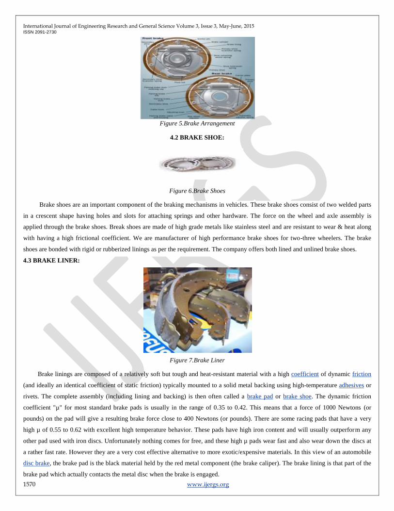
Figure 5.Brake Arrangement
4.2 BRAKE SHOE:
Figure 6.Brake Shoes
Brake shoes are an important component of the braking mechanisms in vehicles. These brake shoes consist of two welded parts
in a crescent shape having holes and slots for attaching springs and other hardware. The force on the wheel and axle assembly is
applied through the brake shoes. Break shoes are made of high grade metals like stainless steel and are resistant to wear & heat along
with having a high frictional coefficient. We are manufacturer of high performance brake shoes for two-three wheelers. The brake
shoes are bonded with rigid or rubberized linings as per the requirement. The company offers both lined and unlined brake shoes.
4.3 BRAKE LINER:
Figure 7.Brake Liner
Brake linings are composed of a relatively soft but tough and heat-resistant material with a high coefficient of dynamic friction
(and ideally an identical coefficient of static friction) typically mounted to a solid metal backing using high-temperature adhesives or
rivets. The complete assembly (including lining and backing) is then often called a brake pad or brake shoe. The dynamic friction
coefficient "µ" for most standard brake pads is usually in the range of 0.35 to 0.42. This means that a force of 1000 Newtons (or
pounds) on the pad will give a resulting brake force close to 400 Newtons (or pounds). There are some racing pads that have a very
high µ of 0.55 to 0.62 with excellent high temperature behavior. These pads have high iron content and will usually outperform any
other pad used with iron discs. Unfortunately nothing comes for free, and these high µ pads wear fast and also wear down the discs at
a rather fast rate. However they are a very cost effective alternative to more exotic/expensive materials. In this view of an automobile
disc brake, the brake pad is the black material held by the red metal component (the brake caliper). The brake lining is that part of the
brake pad which actually contacts the metal disc when the brake is engaged.

International Journal of Engineering Research and General Science Volume 3, Issue 3, May-June, 2015 ISSN 2091-2730
1571 www.ijergs.org
Using a typical bicycle brake as an example, the backing would be the metal shell which provides mechanical support, and the
lining would be the rubbery portion which contacts the rims when the brakes are applied. In most modern vehicular applications the
system is conceptually identical, except the rims would be replaced with solid steel (or sometimes exotic metal) disc. Furthermore, a
metal tang is usually incorporated into the pad assembly. The tang contacts the rotors when the linings are worn out, causing an
annoying noise designed to alert the motorist that brake servicing is required.
Since the lining is the portion of the braking system which converts the vehicle's kinetic energy into heat, the lining must be
capable of surviving high temperatures without excessive wear (leading to frequent replacement) or out gassing (which causes brake
fade, a decrease in the stopping power of the brake).
REQUIREMENTS OF BRAKE LINING:
1. It should have high coefficient of friction with minimum fading.
2. It should have low wear rate.
3. It should have high heat dissipation capacity.
4. It should have high heat resistance.
5. It should have adequate mechanical strength.
6. It should not be affected by moisture and oil.
4.4 METAL ROD:
In Emergency braking we have to wound copper wire to produced magnetic field of required magnetic to force in the wire is
wounded and this rods are mounted and brake shoe in such a way that after the magnetic field is produced the similar rod of
electromagnet will come in contact and hence the repulsion is obtain.
In order to get repulsive force from the rod to which copper wire is wounded. We needed the rods which are good conductor of
electric current and act as a effective magnetic field is produced.
4.5 SOLENOID SWITCH (VALVE):
Figure 8.Solenoid Switch
We manufacture and supply high quality Solenoid switches which are used to switch high power circuits on and off using a much
smaller electrical control signal to actuate the switching. We offer customized ones as well as per the client's requirements. A solenoid
switch is an electromechanical valve for use with liquid or gas. Solenoid switch most frequently used control element in fluidics. They

International Journal of Engineering Research and General Science Volume 3, Issue 3, May-June, 2015 ISSN 2091-2730
1572 www.ijergs.org
are found many application areas. Beside the plunger-type actuator which is used most frequently, pivoted armature and rocker
actuators are also used.
4.6 BATTERY:
The word battery simply means a group of similar components. In military vocabulary, a "battery" refers to a cluster of guns. In
electricity, a "battery" is a set of voltaic cells designed to provide greater voltage and/or current than is possible with one cell alone.
The symbol for a cell is very simple, consisting of one long line and one short line, parallel to each other, with connecting wires:
The symbol for a battery is nothing more than a couple of cell symbols stacked in series:
As was stated before, the voltage produced by any particular kind of cell is determined strictly by the chemistry of that cell type. The
size of the cell is irrelevant to its voltage. To obtain greater voltage than the output of a single cell, multiple cells must be connected in
series. The total voltage of a battery is the sum of all cell voltages. A typical automotive lead-acid battery has six cells, for a nominal
voltage output of 6 x 2.0 or 12.0 volts:
The cells in an automotive battery are contained within the same hard rubber housing, connected together with thick, lead bars
instead of wires. The electrodes and electrolyte solutions for each cell are contained in separate, partitioned sections of the battery
case. In large batteries, the electrodes commonly take the shape of thin metal grids or plates, and are often referred to as plates instead
of electrodes.

International Journal of Engineering Research and General Science Volume 3, Issue 3, May-June, 2015 ISSN 2091-2730
1573 www.ijergs.org
A battery, which is actually an electric cell, is a device that produces electricity from a chemical reaction. Strictly speaking, a
battery consists of two or more cells connected in series or parallel, but the term is generally used for a single cell. A cell consists of a
negative electrode; an electrolyte, which conducts ions; a separator, also an ion conductor; and a positive electrode. The electrolyte
may be aqueous (composed of water) or non aqueous (not composed of water), in liquid, paste, or solid form. When the cell is
connected to an external load, or device to be powered, the negative electrode supplies a current of electrons that flow through the load
and are accepted by the positive electrode. When the external load is removed the reaction ceases.
4.7. SPRING:
A spring is an elastic object used to store mechanical energy. Springs are usually made out of spring steel. Small springs can be
wound from pre-hardened stock, while larger ones are made from annealed steel and hardened after fabrication. Some non-ferrous
metals are also used including phosphor bronze and titanium for parts requiring corrosion resistance and beryllium copper for springs
carrying electrical current (because of its low electrical resistance).
When a spring is compressed or stretched, the force it exerts is proportional to its change in length. The rate or spring constant
of a spring is the change in the force it exerts, divided by the change in deflection of the spring. That is, it is the gradient of the force
versus deflection curve. An extension or compression spring has units of force divided by distance, for example lbf/in or N/m. Torsion
springs have units of force multiplied by distance divided by angle, such as N·m/rad or ft·lbf/degree. The inverse of spring rate is
compliance, that is: if a spring has a rate of 10 N/mm, it has a compliance of 0.1 mm/N. The stiffness (or rate) of springs in parallel is
additive, as is the compliance of springs in series.
Figure 9.Compression Spring
Depending on the design and required operating environment, any material can be used to construct a spring, so long as the
material has the required combination of rigidity and elasticity: technically, a wooden bow is a form of spring. Compression spring is
designed to operate with a compression load, so the spring gets shorter as the load is applied to it.
4.8 OPEN BELT DRIVE
First, let‟s lay out the advantages of a primary belt over a chain. Belt technology these days has produced tough strong belts
that are not quite as strong as a chain, but are coming very, very close. These are being produced at a fraction of the weight of a chain.
Chain drive sprockets are made of steel, while most belt pulleys are hard anodized aluminum. These pulleys are a fraction of the
weight of the sprockets. When a Belt Drive is installed, you are shaving a big chunk of rotating weight out if your driveline. What
does that do for us? When you twist the throttle, your engine accelerates. It has to move all the components hooking the engine to the
tranny, the tranny itself, and the rear drive and wheel. There is a law in Physics that states “everything at rest or in motion tries to stay
in that state until an outside force works upon it”. Because of this law, it takes a certain amount of force to make that change. Now,
going back to our twisted throttle, it takes a certain amount of time (and force) to accelerate the mass of all the components [10]. If we
reduce that mass, the engine doesn‟t have to work as hard, and it will accelerate faster. If you have 2 bikes set up the same way, except

International Journal of Engineering Research and General Science Volume 3, Issue 3, May-June, 2015 ISSN 2091-2730
1574 www.ijergs.org
one has the stock chain primary and the other with a belt drive. Put them side by side and accelerate, the bike with the belt drive will
pull away every time.
Figure 10.Open Belt Drive
CHARACTERISTICS OF ELECTROMAGNETIC BRAKES:
It was found that electromagnetic brakes can develop a negative power which represents nearly twice the maximum power
output of a typical engine, and at least three times the braking power of an exhaust brake (Reverdin 1974). These performances of
electromagnetic brakes make them much more competitive candidate for alternative retardation equipment compared with other
retarders. By using the electromagnetic brake as supplementary. As the above study of all the types of brake and research overview we
are selected disc can be us to develop electromagnetic brake because construction of or disc brake was easy it was much efficient and
fast response for the braking action. The small surfaces area of a disc brake pad and the flat face of the rotor do not simulate a bearing
container. There may be some gas coming from the lining, but because it is not contained well, there is little effect[10]. To repeat, any
drop in friction on a disc brake affects it less than on a drum-brake because the disc brake has no servo action.
Disc-brake cooling is better than drum-brake cooling because the rotor contact surfaces are directly exposed to cooling air.
However, this makes the contact surfaces “potential” more vulnerable to damage from corrosive dirt or water contamination.
Fortunately, the constant wiping keeps the surfaces clean. Also, centrifugal force tends to throw material off the rotor [11]. Because
Disc brake are less sensitive to this contamination than drum brakes. On the other hand, water lubricates a drum well. And, more servo
action means less braking. Disc brake pads are easily changed on more cars. Drum brake are manually adjusted or most have the
added complexity of an automatic-adjusting system. The Disc brake rotor has a contact surfaces on each side; the brake drum has a
contact surfaces only on the inside. Disc-brake swept area is large when compared to a drum brake of the same diameter and weight.
More swept area means better cooling.
CONSTRUCTION AND WORKING OF PROJECT
The back rod is made of pressed steel sheet and is ribbed to increase rigidity and provide support for the anchor and brake shoes. It
also protects the drum and shoe assembly from mud and dust. Moreover it absorbed the complete torque reaction of the shoe due to

International Journal of Engineering Research and General Science Volume 3, Issue 3, May-June, 2015 ISSN 2091-2730
1575 www.ijergs.org
which reason of is some time also called „toque rod‟ friction lining are mounted on the brake shoe one or two reactor spring are used
which serve to keep the brake shoe from the drum when the brake is not applied.
The actuating method consist of two mild steel rod wounded by 24 gauge copper wire of 400 turns on each rods the rod is
attached on anchored brake shoe on the opposite side anchored end. The rod are attached parallel the connection from given rod are to
regulating system and regulating system is attached to the regulator switch is mounted on steering and the connection are provided on
each wheel.
WORKING OF PRINCIPLE
Our project is works on the electromagnetic theory. Emergency brake operates on principle of electromagnetic force providing
to the brake. It is based on the electromagnetic theory. The operation of the brake depends upon the magnetic field produced into rod-
wire winding [13]. The current is supplied by the battery there regulating system which regulates the flow current from the battery and
auxiliary in case provide in failure of battery.
When the regulating switch is operated the current flow battery through all the four wheels. The proportion of current for front
and rear wheel can be set. As the current enters in the winding, the winding energies and the magnetic field is created and which
expand the brake shoe and friction lining comes in contact with brake drum and each time the brake is de-energies and retraction
spring contacts the brake shoe. There electromagnetic force acts against the of retaining spring.
Emergency brake works on,
ELECTROMAGNETIC FLUX
Figure 11 Electromagnetic flux
V-1 Right hand thumb rule: If a piece of copper wire was wound, around the nail and then connected to a battery, it would
create an electro magnet. The magnetic field that is generated in the wire, from the current, is known as the “right hand thumb rule”.
(V-1) The strength of the magnetic field can be changed by changing both wire size and the amount of wire (turns). EM clutches are
similar; they use a copper wire coil (sometimes aluminum) to create a magnetic field.
The fields of EM brakes can be made to operate at almost any DC voltage and the torque produced by the brake will be the
same as long as the correct operating voltage and current is used with the correct brake. If a 90 volt brake had 48 volts applied to it,
this would get about half of the correct torque output of that brake. This is because voltage/current is almost linear to torque in DC
electromagnetic brakes.

International Journal of Engineering Research and General Science Volume 3, Issue 3, May-June, 2015 ISSN 2091-2730
1576 www.ijergs.org
A constant current power supply is ideal for accurate and maximum torque from a brake. If a non regulated power supply is
used the magnetic flux will degrade as the resistance of the coil goes up [14]. Basically, the hotter the coil gets the lower the torque
will be produced by about an average of 8% for every 20°C. If the temperature is fairly constant, and there is a question of enough
service factor in the design for minor temperature fluctuation, by slightly over sizing the brake can compensate for degradation. This
will allow the use of a rectified power supply, which is far less expensive than a constant current supply.
CALCULATION OF FORCES:
No. of turns for copper wire = N = 400
Current = I = 10A, 12 VOLT
MMF = N * I = 400 * 10 = 4000 AT
Reluctance of force
( )
( )
B = 70.53 wb / m2
( )
F = 1139.9 Newton‟s
F = F1 + F2
F = 1139.9 / 2
F1 = 570 N
Stiffness of spring used = 50 N

International Journal of Engineering Research and General Science Volume 3, Issue 3, May-June, 2015 ISSN 2091-2730
1577 www.ijergs.org
Force Extended On Liner = 570N
Figure 12.Wheel attaches with valve and brake drum
MANUFACTURING
It consists of two leading brake shoe placed along the curvature. Brake shoe is consist of mild steel rod over the shoe brake
lining are mounted on the brake shoe. Magnet is formed with the help of mild steel rod. Length of rod is 50 mm. gauge of wounded
wire on mild steel rod is 24 and turn of wounded wire on plate 400 turns per rod. In this way two magnetic coils are made. Brake shoe
are welded to the rod. After completing this process of brake system two ends of magnetic coil are attached to battery terminal to get
12 V.D.C. supply from the battery. The entire assembly of brake system is mounted on a stand [15].
Figure 13.Assembly Of Electromagnetic Brake
ADVANTAGES, LIMITAION AND APPLICATION
ADVANTAGES:

International Journal of Engineering Research and General Science Volume 3, Issue 3, May-June, 2015 ISSN 2091-2730
1578 www.ijergs.org
1. The operating linkage is much simplified in this brake. Instead of complicated linkage as in mechanics brake. This brake
requires only one cable for each drum.
2. Also in this of brake master cylinder as well as wheel cylinder are not needed which reduces the initial cost of brake system.
3. As there are no complicated component such as master cylinder, wheel cylinder the maintenance
4. cost is also low
5. In this system the brake is operated by a regulating knob which reduces driver‟s effort. These brakes require less time for
operation
LIMITATION
This type of brake has only one limitation that the battery should be maintained properly as the current for actuation on brake is
supplied from battery.
APPLICATION
1. It is used over headed crane.
2. It is used in Electric train
3. It is used in Material handling industries for stop the belt drive line
CONCLUSION
During the making of this project “Fabrication of Electromagnetic brake” we got a lot of information and knowledge about the
brake its construction working and principle and how the brake action takes place. While doing this project we came across various
manufacturing process which we learn in books. But due to project we got actual knowledge about the brake system.
Still this brake system is not actual use in vehicle this is a future concept of the brake by using this techniques of brake it was
save the effort of the human being at the maximum level which provide the comfort to the rider of the vehicle. As this brake is require
external power source of battery and it require to charge every time, to overcome this problem one can use dynamo for the charging of
the power is generated itself by the vehicle.
REFERENCES:
[01] Prof. P.L.Balleny, “Theory of Machines and Mechanism”. Page no.574, Twenty second edition 2001, khanna Publication, New
Delhi.
[02] Joseph E. Shingley & Charles R Mischke, “Mechanical Engineering Design ( in SI units)”.Page no.986,sixth edition 2003,TaTa
McGraw Hill Publication Company Limited, New Delhi.
[03] G.B.S.Narang, “Automobile Engineering”. Page no.275, fifth edition 2004, khanna Publication, New Delhi.
[04] Harbans Singh Reyat, “The Automobile”. First edition 1962,S.Chand Publication, New Delhi.
[05] K.M.Gupta. “Automobile Engineering”. Volume 2, Page No.80, Umesh Publication, New Delhi.
[06] S.M. Jang, S.H. Lee, and S.S. Jeong, “Characteristic analysis of eddy-current brake system using the linear Hallbach array,” IEEE

International Journal of Engineering Research and General Science Volume 3, Issue 3, May-June, 2015 ISSN 2091-2730
1579 www.ijergs.org
Trans. Magn., vol. 38, no. 5, pp. 2994-2996, 2002.
[07] Bruno Lequense, “Dynamic model of solenoids under impact excitation, Including Motion and eddy currents,” IEEE Trans. On
Magnetics, Vol 26,1990.
[08] Richard Shemanske, “Electronic Motor Braking,” IEEE Trans. On Industry Applications, vol.IA-19,pp.824-831,Apr.1983.
[09] Timo T. Vekara, Jarl-Thure Eriksson and Juha T.Tanttu,”Dynamic model of an Electromagnetic Massive Core Brake Actuator,”
IEEE Trans. On Magnetics, Vol. 32, 1996.
[10] M.A. Heald, “Magnetic Braking: Improved Theory,” American journal of physics, vol.56, no.6, pp.521-522,1988.
[11]. Tatsuya Yamasaki, Masaaki Eguchi And Yusuke Makino, Development of an Electromechanical Brake, NTN Technical Review
No.75(2007) Heaviside, O.W., Electromagnetic Theory, Vol I (London, 1893)
[12] Chihoon jo , sungho hwang and Hyunsoo kim, Clamping-force control for electromechanical brake ,Vehicular technology, IEEE
transactions on (volume:59 , issue: 7 ) sept. 2010, 3205 – 3212.
[13] Virendra Kumar Maurya, Rituraj Jalan1, H. P. Agarwal, S. H. Abdi, Dharmendra Pal, G. Tripathi and S. Jagan Raj, Eddy Current
Braking Embedded System, International Journal of Applied Engineering and Technology , 104-113
[14] William Gaskey, Sandip Mistry, Duy Nguyen, Jee Yoon, Electromagnetic Braking System Ahfock, A., Toowoomba, QLD Wells,
C.G., A practical demonstration of electromagnetic braking, Power Engineering Conference, AUPEC 2007 Australasian
Universities, 9-12 Dec.2007.
[15] A. Lesobre, A.H. Ben Ahmed, and D. Drecq, “An analytical dynamic model of eddy-current brakes,” in Proc. IEEE International
Electric Motor Drive Conference. Cambridge, MA: 2001, pp. 122-125