Embed Size (px)
Citation preview

International Journal of Engineering and Information Systems (IJEAIS)
ISSN: 2000-000X
Vol. 2 Issue 9, September – 2018, Pages: 10-20
www.ijeais.org 10
Numerical Calculation Analysis of Lift and Bow Thruster
Design of Class LCAC Hovercraft Sutikno Wahyu Hidayat
1,Ahmadi
2,Okol S Suharyo
3,Arica Dwi Susanto
4
1Indonesian Naval Technology College,
Bumimoro-Morokrembangan, Surabaya 60187, Indonesia
Email: [email protected] 2Indonesian Naval Technology College,
Bumimoro-Morokrembangan, Surabaya 60187, Indonesia
E-mail: [email protected] 3Indonesian Naval Technology College,
Bumimoro-Morokrembangan, Surabaya 60187, Indonesia
E-mail: [email protected] 4Indonesian Naval Technology College,
Bumimoro-Morokrembangan, Surabaya 60187, Indonesia
E-mail: [email protected]
Abstract-Class LCAC Hovercraft is a hovercraft which has the ability to support military operations in the fields of
transport and distribution of logistics and other combat equipments. Indonesia only has a hovercraft which is used to
transport personnels only. This study aimed to analyze the calculation of lift style and design of the bow thruster to
obtain the great style and the right blade design in detail. Therefore, the characteristics corresponding to the results of
numerical calculation of 200.56 m3/s Air Volume Elevator Volume, 4905.5 N/m
2Total fan pressure, 1000 mm Outside
diameter, 700 mm Input Diameter, 15 Blades, 322 mm Impeller Leaf Width, 0.776 Efficiency could be obtained.
Keywords-Hovercraft, Lift, Bow Thruster, LCAC
I. INTRODUCTION
The development of maritime science and
technology, in particular the interests of logistic shifts,
tends to lead to the use of more effective and more
flexible and high mobility main equipments(L.Trillo,
1971). Hovercraft is able to provide greater benefits and
efficiencies and can move in all terrain because the
friction is smaller than the ground and ship vehicles, so
this vehicle is also safe to cross mine-planted beach
without activating the mine (Saad, 2017).
This paper have any literature to support the
research about it, for example paper with title Dynamic
Stability of Hovercraft in Heave (Poland, 1970).
Development of a Hovercraft Prototype (Okafor, 2013).
Dynamic Mathematical Modeling and Simulation Study
of Small Scale Autonomous Hovercraft (M. Z. A.
Rashid, 2012). RC Hovercraft: An I-Bylogical Enzyme
(I-BE) Biosensor Carrier (Rinta Kridalukmana, 2017).
To Study and Fabrication of Air Cushion Vehicle
(Tiwari, 2015). Type of Ship Trim Analysis on Fuel
Consumption with a Certain Load and Draft (I Nengah
Putra, 2017). Air Assisted Directional Control of a
Hovercraft (RAJMANOVAH, 2014). Design & Air
Flow Simulation of Small Scale Working Model Of
Hovercraft (A. V. Kale, 2017). A Study On
Construction and Working Principle of a Hovercraft (V
Abhiram, 2014). Comparative Analysis Result of
Towing Tank and Numerical Calculations With
Harvard Guldammer Method (I Nengah Putra A. D.,
2017). Development of a Integrated Air Cushioned
Vehicle (Hovercraft) (S.V. Uma Maheswara Rao,
2014). Diagnosis of Fault Modes Masked by Control
Loops with an Application to Autonomous Hovercraft
Systems (Christopher Sconyers, 2013). Hovercraft
Control With Dynamic Parameters Identification (David
Cabecinhas, 2017). Analysis of The Propulsion System
Toward The Speed Reduction of Vessels Type PC-43
(Arica Dwi Susanto, 2017). Designing Hovercraft
Controlled using Android (Pankaj Singh, 2016).
Development of a working Hovercraft model (S H
Mohamed Noor, 2015). Study of Water Jet Propulsion
System Design For Fast Patrol Boat (FPB-60)
(Prihanto, 2018). Development of a hovercraft
prototype with an aluminium hull base (A. K.
Amiruddin, 2011). (William B. Dunbar, 2003). Stokes
Equation in a Toy CD Hovercraft (Izarra, 2011).
The development of hovercraft, especially the
mastery of hovercraft technology, is one of the
alternative options of Indonesian Navy in order to
develop defense and security forces. In designing a
hovercraft up to its manufacture, we have to pay
attention to the weight factor of the vehicle, and it
requires proper planning which concerns with the
structure of construction to provide the body shape of
the hovercraft. The authors analyzed the lifting blower
and bow thruster on LCAC type hovercraft in detail

International Journal of Engineering and Information Systems (IJEAIS)
ISSN: 2000-000X
Vol. 2 Issue 9, September – 2018, Pages: 10-20
www.ijeais.org 11
with the calculation of lifting style and design of the
bow thruster so that the style and design of the right
blade in detail can be obtained. Thus, the demands of
technical capabilities and hovercraft operations
capability of LCAC class can be fulfilled.
This Paper is organized as follows. Section 2
review about the basic ship theory. Section 3 gives
result and 4 discussion of research. Finally, in section 5
present conclusion this paper.
II. RESEARCH METHODOLOGY
2.1. The Definition of Hovercraft
Hovercraft is a type of amphibious fast ship
with a trapped air in which the whole body position
(hull) of this type of vehicle does not touch the ground
surface (soil, water, etc.) and moves with the impulse of
the fan (Thrust Fan) (Yahya, 1987). The hull force itself
comes from the pressurized air just below the hovercraft
hull (Plenum Chamber), in which there is no
construction other than compressed air inside this
plenum chamber. The amphibian capability of this
hovercraft is the main difference from boat, motor boat,
ship or hydrofoil, although all of them have the same
speed at high speed. In its development, Hovercraft has
a name or other designations: Air Cushion Vehicle
(ACV), Capture Air Bubble (CAB), and Ground Effect
Machine (GEM). However, hovercraft is the most
common name used to date (Roshan R. Shrirao, 2016).
2.2. Definition of Lifter and Bow Thruster
Lifter or lift is the main system in hovercraft
operations which uses high-pressure air supply, the
outside air compressor which is then pressed into a
plenum chamber surrounded by skirt (hovercraft
component that serves as a protective air) (Key, 1987).
From this process, therefore, the air supply forms the
"air cushion". This air cushion is called static air
cushion. The process is that air is supplied constantly so
that the air pressure presenting in the plenum space
becomes higher and increases than that outside. Thus,
the air will come out through the gap under the skirt by
itself which will then give rise to lift in hovercraft. So,
hovercraft will be lifted and hovered by itself from the
surface of the water or the ground, but not flying like a
plane.
Whereas, the Bow Thruster is a system used to
provide a positive setting for ship bow movement
caused by cross-wind or ocean stream. The
effectiveness of Bow-thruster can be determined from
the thrust force generated by electric or hydraulic
motors in KW or HP.
Based on the propulsion, there are 3 types of Bow
Thruster (L.Trillo, 1971):
1. Hydraulic Bow Thruster
2. Electric Bow Thruster
3. Diesel powered Bow Thruster
2.3. Principle of the Lift System
As we know, hovercraft is a ship that operates
with the whole hull lifted by the force generated by the
pressurized air located in the Plenum Chamber region
(Perozzo, 1995).
Fig. 1, The principle of lift style on hovercraft
The lift/air pressure in the Plenum Chamber
can be adjusted according to the airflow exhaled by the
lifter fan (Lift fan). Although when air is blown down
the hull of the hovercraft, there is already airflow out
through the hover gap. However, since the fan lift blows
air with a much larger flow, the air pressure that occurs
in the Plenum Chamber is getting bigger and bigger.
This pressure will get bigger and stronger to be pushed
out through the bottom of the hovercraft, so that the
hover gap formed is also getting bigger. This increase
of pressure will continue until the height of the planned
hover gap is reached. Whereas, the process of lift (lift
process) from hovercraft itself can be divided into two
stages, namely stage inflating skirt (hovering) and
flying stage (Perozzo, 1995).
Fig. 2, Lift System Diagram
2.4. Hovering Stage
This stage is the process of inflating skirts
from the process of empty skirt (off hover) until it
reaches full-fledged position (full hover) (Perozzo,
1995).

International Journal of Engineering and Information Systems (IJEAIS)
ISSN: 2000-000X
Vol. 2 Issue 9, September – 2018, Pages: 10-20
www.ijeais.org 12
Fig. 3, Hovering phase of hovercraft
The planning of hovering stage is determined
by the air pressure in the skirt used. The ratio of air
pressure in skirt and air pressure in Plenum Chamber is
about 1.2 which further determines the required fan
power according to the equation:
PH = PSkirt X QSkirt (1)
2.5. Flying Stage
The flying stage is the process in which the
hovercraft is lifted entirely above the runway surface
after the skirt is in full hover position(Perozzo, 1995).
Fig. 4, Flying Stage of hovercraft
To perform the stage of hovering or inflating
skirts from the vacant position of the skirt (off hover)
until it reaches the full hover position and the flying
stage or process in which the hovercraft is lifted entirely
above the runway surface after the skirt is in the hover
position, there are some very related points to the
design of the flying stage of hovercraft as follows:
(Rajamani, 2015)
1. Lift Length Parameter
Lift Parameters are the circumference
of the area under the hovercraft that is
formed and limited by the skirt
tangent line with the runway when the
hovercraft is in full hover condition.
The value of lift parameter is the
circumference of the hovercraft body
reduced by a certain percentage as a
conversion factor because in general,
the lower part of the hovercraft body
has a certain slope shape.
PL = k.PH (2)
2. Hover Gap Area (AHG)
Hover Gap Area or wide hover gap is
the area of vertical area which is
formed when the hovercraft is lifted
up (flying). Thus, the width of this
area is the multiplication of lift
parameters with a hover slit. By
estimating the hover gap, the width of
the hover gap can be calculated by the
following equations:
AHG = PL X GH (3)
3. Cushion Pressure (PC)
Cushion Pressure or hover pressure is
the total weight of hovercraft (at full
load) that works on the area of the
field under hovercraft body. Same
with lift parameter, the width of this
press field is the area of the ship after
it is converted. So, the hover pressure
working under the ship's body is:
PC = WT / APC (4)
4. Escaping Air Velocity (VE)
Escaping Air Velocity is the air
velocity that comes out of the hover
gap when the hovercraft body is lifted
up. Furthermore, the value obtained
from the table should be converted in
practical conditions in the field which
must have a temperature difference,
so the value which can be taken is
60% of the value obtained from the
table, as follows: (Perozzo, 1995)
Table 1, Relation of hover pressure and air velocity,
measured under air conditions with a temperature of
70°F
Hover Pressure
(psi)
Air Velocity (fps)
0.050 78
0.075 96
0.100 111
0.125 123
0.150 135
0.175 146
0.200 156
Then we will get the actual air speed
figure of:
VEA = 60% X VET (5)
5. Air lift debit (QL)

International Journal of Engineering and Information Systems (IJEAIS)
ISSN: 2000-000X
Vol. 2 Issue 9, September – 2018, Pages: 10-20
www.ijeais.org 13
Air lift debit is the volume of air that
passes through the hover gap per unit
of time, so that the air debit can be
calculated as follows:
QL = VEA XGH (6)
6. Theoretical & Actual Power for
Hovercraft Lifts (PT)
The power required to lift the
hovercraft is the result of the hover
pressure with the air debit working
under the hovercraft, so it will be
obtained as follows:
PT = PC X QL (7)
2.6. Fan Working Principle
Fan is one type of fluid engine that serves to
move the fluid (air) with a certain direction and speed in
accordance with the characteristics of the rotor
(impeller) fan used (A.Anandhakumar, 2015).
The air capacity that the fan can move is
largely determined by the size of the fan, the speed of
rotation and the channeling system used in conjunction
with the fan itself. According to the direction of the
resulting airflow, the fan can be divided into two types:
centrifugal fan and axial fan. Based on its impeller
leaves, centrifugal fans are divided into 6 categories:
AF (airfoil), BC (backward-curved), BI (backward-
inclined), RT (radial-tip), forward-curved FC, and RB
(radial blade) (Liang Yun, 2000).
Fig. 5, Efficiency of impeller leaves
2.7. Centrifugal Fan
It is called a centrifugal fan because this type
of fan generates air from the input area (inlet) to the
outlet region in the radial direction due to the
centrifugal force generated by the impeller rotation
(Perozzo, 1995).
Fig. 6, Airflow of the centrifugal fan
Furthermore, the air is radially thrown out the
impeller with high speed and pressure and then enters
the fan casing in the form of a spiral. The spiral shape
of the fan casing acts as an aerial drive towards the exit
portion of the fan, and from this spiral shape then the
centrifugal fan casing is also called the scroll or volute.
In practical condition, the centrifugal fan is a blower
that can operate with an air pressure ratio of 1000 mm
W.G by double inner (L.Allison, 1990).
Fig. 7, Schematic centrifugal fan Impeller
According to the air pressure that can be
produced, the centrifugal fan can be divided into 3 main
groups, namely: (Raj, 2017)
1. Low pressure fan up to 0.981 kPa
2. Medium pressure fan from 0.981 to
2.943 kPa
3. High pressure fan from 2.943 to 11.772
kPa
2.8. Method of Research
In planning the system of lifter and bow
thruster, it is not apart from the calculation of empty
weight and weight of charge that will be placed on
hovercraft that will be designed later. This is because in
its principle, the system of lifter and bow thruster will
counteract the force caused by the weight of the
construction which is nothing but the weight of the
design of the hovercraft itself.
Therefore, in planning a hovercraft, we must
consider several main factors, including the main size,
machine requirements and geometric shapes. Thus, the
right selection and calculation must be done, so that the
requirement of lift and thrust power demanded in the
planning will be guaranteed.
III. RESULTS AND DISCUSSION

International Journal of Engineering and Information Systems (IJEAIS)
ISSN: 2000-000X
Vol. 2 Issue 9, September – 2018, Pages: 10-20
www.ijeais.org 14
3.1. Power Requirement Calculation
The power for the engine lift is the amount of
power required to lift the overall hovercraft as high as
the height of the skirt from the bottom surface. Thus, in
order to have the profile, the layout of lift system type
and pressure distribution at various positions are
displayed as follows: (Liang Yun, 2000)
Fig. 8, Layout of lift system type and pressure distribution at various positions
Table 2, Power Requirement Calculation
No Power Requirement Calculation Calculation results
1 Lift Parameter Calculation 50.22 M
2 Hover Gap Area (AHG) Calculation 0.637 M2
3 Cushion Pressure (PC) Calculation 3703.48 Pa ≈ 35 bar ≈ 34.8 atm
4 Determination of Lift Air Volume (Q) 200.56 m3/s
5 Determination of Impeller Fan Diameter (D2) 1.03 ≈ 1 m
6 Determination of Impeller Disc Width (F) 0.81 m
7 Determination of Air Fan Volume Coefficient (Q’) 3
8 Determination of Total Fan Pressure Coefficient (H’) 0.61
9 Determination of Total Fan Pressure (H ) 4905.5 N/m2
Table 3, Fan Selection
No Fan Selection Calculation Results
1 Impeller Diameter 1.025 ≈ 1 m
2 Input Area Impeller Diameter 0.7 m
3 Leaf Impeller Width 0.322 m
IV. DISCUSSION
Drawing design planning for lifter and bow
thruster system begins with partial or part-by-piece
depiction and forwarded to assembling and laying on
the space which has already designed in this LCAC
class hovercraft model. Based on the results of the
numerical calculation, we obtains the dimensions used
in this planning:
4.1. Impeller
Fig. 9, Impeller and its blades (front view)

International Journal of Engineering and Information Systems (IJEAIS)
ISSN: 2000-000X
Vol. 2 Issue 9, September – 2018, Pages: 10-20
www.ijeais.org 15
Fig. 10, Impeller and its blades (isometric view)
Fig. 11, Impeller and its blades (side view)
Fig. 12, Shaft and head (side view)
4.2. Assembly
Fig. 13, Axle, Impeller and head cushion assembly (side
view)
Fig. 14, Shaft, Impeller and Cushion Assembly (front
view)
International Journal of Engineering and Information Systems (IJEAIS)
ISSN: 2000-000X
Vol. 2 Issue 9, September – 2018, Pages: 10-20
www.ijeais.org 16
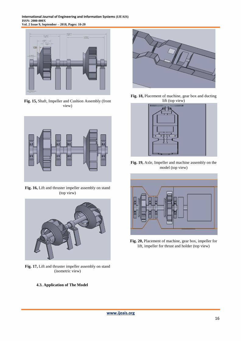
Fig. 15, Shaft, Impeller and Cushion Assembly (front
view)
Fig. 16, Lift and thruster impeller assembly on stand
(top view)
Fig. 17, Lift and thruster impeller assembly on stand
(isometric view)
4.3. Application of The Model
Fig. 18, Placement of machine, gear box and ducting
lift (top view)
Fig. 19, Axle, Impeller and machine assembly on the
model (top view)
Fig. 20, Placement of machine, gear box, impeller for
lift, impeller for thrust and holder (top view)

International Journal of Engineering and Information Systems (IJEAIS)
ISSN: 2000-000X
Vol. 2 Issue 9, September – 2018, Pages: 10-20
www.ijeais.org 17
Fig. 21, Placement of machine, gearbox, impeller for
lift, impeller for thrust and stand (isometric view)
Fig. 22, Placement of machine, gear box, impeller for
lift, impeller for thrust and holder (top view)
Fig. 23, Placement of machine, gear box, impeller for
lift, impeller for thrust and holder (isometric view)
Fig. 24, The mechanism of the bow thruster drive with
an electric motor (front view)
Fig. 25, The mechanism of the bow thruster drive with
an electric motor (isometric view)

International Journal of Engineering and Information Systems (IJEAIS)
ISSN: 2000-000X
Vol. 2 Issue 9, September – 2018, Pages: 10-20
www.ijeais.org 18
Fig. 26, Bow Thruster on the model (side view)
Fig. 27, Lifter and bow Thruster system on closed
model
V. CONCLUSION
Using the results of the analysis and
calculation of the lift style and the design of the bow
thruster, we obtained the great style and the right blade
design in detail. Thus, the researchers obtained the
characteristics according to the numerical calculation
results: 200.56 m3/s Lift Air Volume, 4905.5 N/m
2Total
fan pressure, 1000 mm Outside diameter, 700 mm Input
Diameter, 15 Blades, 322 mm Width of Leaves
Impeller, and 0.776 Efficiency.
VI. ACKNOWLEDGEMENTS
This research has been Supported by Indonesia Naval
Technology College (STTAL).
VII. REFERENCES
A. K. Amiruddin, S. M. (2011). Development of a
hovercraft prototype with an aluminium hull base.
International Journal of the Physical Sciences , 6,
4185-4194.
A. V. Kale, A. J. (2017). Design & Air Flow Simulation
of Small Scale Working Model Of Hovercraft. IOSR
Journal of Mechanical and Civil Engineering (IOSR-
JMCE) , 23-28.
A.Anandhakumar, S. S. (2015). Design and Fabrication
of Hovercraft. International Journal of Innovative
Research in Science Engineering and Technology , 4
(6), 597-601.
Adumene, N. S. (2015). Predictive Analysis of Bare-
Hull Resistance of a 25,000 Dwt Tanker Vessel.
International Journal of Engineering and Technology ,
194-198.
Amin, J. K. (2014). Performance of VLCC Ship with
Podded Propulsion System and Rudder. International
Society of Ocean, Mechanical and Aerospace Scientists
and Engineers , 1-7.
Andersen, J. P. (1994). Hydrodynamic of Ship
Propeller. Cambridge: Elsevier.
Anthony F. Molland, S. R. (2011). Ship Resistance and
Propulsion. United Stated of America: Practical
Estimation of Ship Propulsive Power.
Arica Dwi Susanto, A. O. (2017). Analysis of The
Propulsion System Toward The Speed Reduction of
Vessels Type PC-43. International Journal of
Engineering Research and Application , 7 (4), 08-15.
Atreyapurapu.et.al, K. (2014). Simulation of a Free
Surface Flow over a Container Vessel Using CFD.
International Journal of Engineering Trends and
Technology , 334-339.
Bartee, D. L. (1975). Design of Propulsion Systems for
Hidh-Speed Craft. The Society of Naval Architects and
Marine Engineers , 1-17.
Bertram, H. S. (1998). Ship Design for Efficiency and
Economy. Great Britain: Butterworth-Heinemann.
Bertram, V. (2000). Practical Ship Hydrodynamic.
Inggris: Great Britain.
Charchalis, A. (2013). Designing Constraints in
Evaluation of Ship Propulsion Power. Journal of
KONES Powertrain and transport , 1-6.
Christopher Sconyers, Y.-K. L. (2013). Diagnosis of
Fault Modes Masked by Control Loops with an
Application to Autonomous Hovercraft Systems.
International Journal of Prognostics and Health
Management , 1-15.
Chun.et.al., H. H. (2013). Experimental investigation on
stern-boat deployment system and operability for
Korean coast guard ship. International Journal Naval
Architecture Ocean Engineering , 488-503.
D'arcalengelo, A. M. (1969). Ship Design and
Contruction. Michigan: Professor of Naval Architecture
and Marine Engineering University of Machigan.
David Cabecinhas, P. B. (2017). Hovercraft Control
With Dynamic Parameters Identification. IEEE
TRANSACTIONS ON CONTROL SYSTEMS
TECHNOLOGY , 1-12.
Degiuli.et.al., N. (2017). Increase of Ship Fuel
Consumption Due to the Added Resistance in Waves.
Journal of Sustainable Development of Energy, Water
and Environment Systems , 1-14.
Gerr, D. (2001). Propeller Handbook. (J. E.
Oppenheim, Penyunt.) United Stated: International
Marine.
Guldhammer, H. E. (1974). Ship Resistance.
Copenhagen: Akademisk Forlag.

International Journal of Engineering and Information Systems (IJEAIS)
ISSN: 2000-000X
Vol. 2 Issue 9, September – 2018, Pages: 10-20
www.ijeais.org 19
Harrington, R. L. (1992). Marine Engineering (Revised,
Subsequent ed.). (Revised, Penyunt.) Jersey City,
United States: The Society of Naval Architects and
Marine Engineers .
Harvald, S. A. (1992). Resistance and Propulsion of
Ships. New York: John Wiley and Sons.
Herdzik, J. (2013). Problems of propulsion systems and
main engines choice for offshore support vessels.
Scientific Journals Zeszyty Naukowe , 2 (1733-8670),
45-50.
I Nengah Putra, A. D. (2017). Comparative Analysis
Result of Towing Tank and Numerical Calculations
With Harvard Guldammer Method. International
Journal of Applied Engineering Research , 12 (21),
10637-10645.
I Nengah Putra, A. D. (2017). Type of Ship Trim
Analysis on Fuel Consumption with a Certain Load and
Draft. International Journal of Applied Engineering
Research , 12 (21), 10756-10780.
Izarra, C. d. (2011). Stokes Equation in a Toy CD
Hovercraft. European Journal of Physics , 89-99.
Key, R. L. (1987). Hovercraft Skirt Design and
Manufacture. Journal of Engineering Manufacture ,
209-219.
Kleppesto, K. (2015). Empirical Prediction of
Resistance of Fishing Vessels. NTNU Trondheim
Norwegion University of Science And Technology , 1-
87.
Kowalski, A. (2013). Cost optimization of marine fuels
consumption as important factor of control ship’s sulfur
and nitrogen oxides emissions. Scientific Journals , 94-
99.
Kuiper, G. (1992). The Wageningen Propeller Series.
Netherland: MARIN.
L.Allison, J. (1990). Air Cushion Vehicle and Survace
Effect Ships for Great Lakes and Great River
Transportation. Marine Technology , 27, 1-8.
L.Trillo, R. (1971). Marine Hovercraft Technology.
London: Leonardo Hill.
Lewis, E. V. (1988). Principles of Naval Architecture
Second Revision. New Jersey: The Society of Naval
Architecs and Marine Engineers.
Liang Yun, A. B. (2000). Theory and design of air
cushion craft. New York: Wiley.
M. Z. A. Rashid, M. S. (2012). Dynamic Mathematical
Modeling and Simulation Study of Small Scale
Autonomous Hovercraft. International Journal of
Advanced Science and Technology , 46, 95-114.
Okafor, B. (2013). Development of a Hovercraft
Prototype. International Journal of Engineering and
Technology , 3, 276-281.
Pankaj Singh, A. B. (2016). Designing Hovercraft
Controlled using Android. International Journal of
Engineering Trends and Technology (IJETT) , 37-42.
Perozzo, J. (1995). Hovercraft as a Hobby. Auburn:
Twin peaks Enterprise.
Poland, H. J. (1970). Dynamic Stability of Hovercraft in
Heave. Journal of Applied Mechanics , 37 (4), 895-900.
Premchand, P. K. (2015). Numerical Investigation of
the Influence of Water Depth on Ship Resistance .
International Journal of Computer Applications , 1-8.
Prihanto, A. D. (2018). Study of Water Jet Propulsion
System Design For Fast Patrol Boat (FPB-60).
International Journal of Academic and Applied
Research (IJAAR) , 2 (7), 1-7.
Raj, A. A. (2017). Design of An Unmanned Hovercraft.
International Journal of Computer Engineering in
Research Trends , 4 (5), 190-194.
Rajamani, V. K. (2015). Design and Analysis of
Winged Hovercraft. Journal of Applied Mechanical
Engineering , 4 (5), 1-8.
RAJMANOVAH, B. S. (2014). AIR ASSISTED
DIRECTIONAL CONTROL OF A HOVERCRAFT.
International Journal of Mechanical And Production
Engineering , 2 (9), 88-91.
Rinta Kridalukmana, B. C. (2017). RC Hovercraft: An
I-Bylogical Enzyme (I-BE) Biosensor Carrier.
International Journal of Electrical and Computer
Engineering (IJECE) , 7, 2003-2007.
Roshan R. Shrirao, S. P. (2016). Design & Fabrication
of ACV. International Journal of Emerging Trends in
Science and Technology , 3 (5), 3995-4015.
S H Mohamed Noor, K. S. (2015). Development of a
working Hovercraft model. IOP Publishing , 1-9.
S.V. Uma Maheswara Rao, V. S. (2014). Development
of a Integrated Air Cushioned Vehicle (Hovercraft).
International Journal of Modern Engineering Research
(IJMER) , 4 (5), 21-28.
Saad, K. A. (2017). The Development of Hovercraft
Design with a Horizontal Propulsion System.
Engineering Applications for New Materials and
Technologies , 91-103.
Samson, D. I. (2015). Effect of Fluid Density On Ship
Hull Resistance and Powering. International Journal of
Engineering Research and General Science , 615-630.

International Journal of Engineering and Information Systems (IJEAIS)
ISSN: 2000-000X
Vol. 2 Issue 9, September – 2018, Pages: 10-20
www.ijeais.org 20
Samuel, M. I. (2015). An Inventigation Into The
Resistance Components of Converting a Traditional
Monohull Fishing Vessel Into Catamaran Form.
International Journal of Technology , 1-10.
Sladky, J. (1976). Marine Propulsion. New York: The
Winter Annual Meeting of The American Society of
Marine Engineers.
Susanto.et.al., A. D. (2017). Analysis of The Propulsion
System Towards The Speed Reduction of Vessels Type
PC-43. International Journal of Engineering Research
and Application , 8-15.
Tabaczek, J. K. (2014). Coefficients of Propeller-hull
Interaction in Propulsion System of Inland Waterway
Vessels with Stern Tunnels. International Journal on
Marine Navigation and Safety of Sea Transportation ,
1-8.
Tiwari, A. (2015). TO STUDY AND FABRICATION
OF AIR CUSHION VEHICLE. INTERNATIONAL
JOURNAL of RESEARCH–GRANTHAALAYAH , 3, 70-
84.
Tupper, E. (1975). Introduction to Naval Architecture.
Inggris: Great Britain.
Tupper, K. R. (2001). Basic Ship Theory. Inggris: Great
Britain.
V Abhiram, N. S. (2014). A STUDY ON
CONSTRUCTION AND WORKING PRINCIPLE OF
A HOVERCRAFT. International Journal of
Mechanical Engineering and Robotics Research , 3,
308-313.
Watson, D. G. (1998). Practical Ship Design.
Netherlands: Elsevier Science Ltd.
William B. Dunbar, R. O. (2003). Nonlinear and
Cooperative Control of Multiple Hovercraft With Input
Constraints . European Control Conference (ECC) (hal.
1917-1922). Cambridge: IEEE Xplore digital library.
WPA Van Lamerren, T. L. (1984). Resistance
Propulsion and Steering of Ship. Holland: Harleem
Holland.
Yahya, S. M. (1987). Turbines Compressors and Fans.
New Delhi: Tata McGraw-Hill.
Zelazny, K. (2014). Amethod of Calculation of Ship
Resistance on Calm Water Useful at Preliminary Stages
of Ship Design. Scientific Journal Maritime University
of Szuczecin , 125-130.
Żelazny, K. (2015). An Approximate Method For
Calculation of Mean Statistical Value of Ship Service
Speed On a Given Shipping Line , Useful In
Preliminary Design Stage. Polish Maritime Research ,
28-35.