Embed Size (px)
Citation preview
PLEASE SCROLL DOWN FOR ARTICLE
This article was downloaded by: [Univ Degli Studi di Brescia]On: 22 March 2011Access details: Access Details: [subscription number 933608154]Publisher Taylor & FrancisInforma Ltd Registered in England and Wales Registered Number: 1072954 Registered office: Mortimer House, 37-41 Mortimer Street, London W1T 3JH, UK
International Journal of Architectural HeritagePublication details, including instructions for authors and subscription information:http://www.informaworld.com/smpp/title~content=t741771160
Wooden Roof Box Structure for the Anti-Seismic Strengthening of HistoricBuildingsEzio Giuriania; Alessandra Marinia
a Department of Civil, Architectural, Environmental and Land Planning Engineering (DICATA),University of Brescia, Brescia, Italy
To cite this Article Giuriani, Ezio and Marini, Alessandra(2008) 'Wooden Roof Box Structure for the Anti-SeismicStrengthening of Historic Buildings', International Journal of Architectural Heritage, 2: 3, 226 — 246To link to this Article: DOI: 10.1080/15583050802063733URL: http://dx.doi.org/10.1080/15583050802063733
Full terms and conditions of use: http://www.informaworld.com/terms-and-conditions-of-access.pdf
This article may be used for research, teaching and private study purposes. Any substantial orsystematic reproduction, re-distribution, re-selling, loan or sub-licensing, systematic supply ordistribution in any form to anyone is expressly forbidden.
The publisher does not give any warranty express or implied or make any representation that the contentswill be complete or accurate or up to date. The accuracy of any instructions, formulae and drug dosesshould be independently verified with primary sources. The publisher shall not be liable for any loss,actions, claims, proceedings, demand or costs or damages whatsoever or howsoever caused arising directlyor indirectly in connection with or arising out of the use of this material.
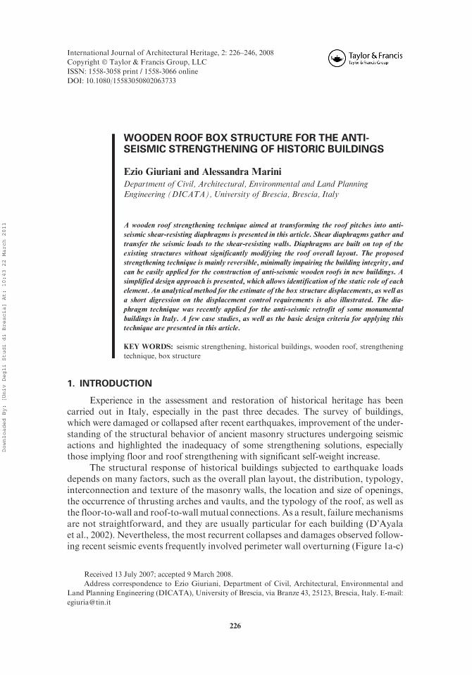
WOODEN ROOF BOX STRUCTURE FOR THE ANTI-SEISMIC STRENGTHENING OF HISTORIC BUILDINGS
Ezio Giuriani and Alessandra Marini
Department of Civil, Architectural, Environmental and Land PlanningEngineering (DICATA), University of Brescia, Brescia, Italy
A wooden roof strengthening technique aimed at transforming the roof pitches into anti-
seismic shear-resisting diaphragms is presented in this article. Shear diaphragms gather and
transfer the seismic loads to the shear-resisting walls. Diaphragms are built on top of the
existing structures without significantly modifying the roof overall layout. The proposed
strengthening technique is mainly reversible, minimally impairing the building integrity, and
can be easily applied for the construction of anti-seismic wooden roofs in new buildings. A
simplified design approach is presented, which allows identification of the static role of each
element. An analytical method for the estimate of the box structure displacements, as well as
a short digression on the displacement control requirements is also illustrated. The dia-
phragm technique was recently applied for the anti-seismic retrofit of some monumental
buildings in Italy. A few case studies, as well as the basic design criteria for applying this
technique are presented in this article.
KEY WORDS: seismic strengthening, historical buildings, wooden roof, strengthening
technique, box structure
1. INTRODUCTION
Experience in the assessment and restoration of historical heritage has beencarried out in Italy, especially in the past three decades. The survey of buildings,which were damaged or collapsed after recent earthquakes, improvement of the under-standing of the structural behavior of ancient masonry structures undergoing seismicactions and highlighted the inadequacy of some strengthening solutions, especiallythose implying floor and roof strengthening with significant self-weight increase.
The structural response of historical buildings subjected to earthquake loadsdepends on many factors, such as the overall plan layout, the distribution, typology,interconnection and texture of the masonry walls, the location and size of openings,the occurrence of thrusting arches and vaults, and the typology of the roof, as well asthe floor-to-wall and roof-to-wall mutual connections. As a result, failure mechanismsare not straightforward, and they are usually particular for each building (D’Ayalaet al., 2002). Nevertheless, the most recurrent collapses and damages observed follow-ing recent seismic events frequently involved perimeter wall overturning (Figure 1a-c)
International Journal of Architectural Heritage, 2: 226–246, 2008
Copyright � Taylor & Francis Group, LLC
ISSN: 1558-3058 print / 1558-3066 online
DOI: 10.1080/15583050802063733
Address correspondence to Ezio Giuriani, Department of Civil, Architectural, Environmental and
Land Planning Engineering (DICATA), University of Brescia, via Branze 43, 25123, Brescia, Italy. E-mail:
Received 13 July 2007; accepted 9 March 2008.
226
Downloaded By: [Univ Degli Studi di Brescia] At: 10:43 22 March 2011

and, in some churches, the rocking of the transverse arch pillars (Figure 1d). Thepillar-rocking motion induced large differential displacements between neighboringdiaphragm-arches, thus resulting in severe damages to the possible nave vaults. It isworth noting that, following the strong earthquake in the Benaco area in northernItaly in year 2004, these unconstrained differential displacements were recognized asthe major cause of the ruin of the nave vaults of two churches.
Global peripheral wall overturning and excessive pillar rocking occurred whenthe floors, the roof and the possible peripheral ties provided insufficient confinementof the toppling seismic action, which was eventually further increased by the horizon-tal thrust of the wooden roof (Figure 1a, c).
In order to improve the seismic resistance of ancient buildings, different earth-quake-resistant features are traditionally proposed, namely: perimeter ties or floordiaphragms. Perimeter horizontal steel ties are inadequate in the case of unfavorablelength-to-thickness ratios of the transversally loaded masonry walls. In this scenario,floor and roof diaphragms are frequently proposed against peripheral wall overturn-ing to improve the seismic resistance (Giuriani and Marini, 2002; Giuriani, 2004). Inthe case of churches or in the case of buildings having at-sight wooden roofs, only roofdiaphragms can be arranged.
In this article, the box structure solution is addressed with concern to theformation of thin roof diaphragms. The roof pitches are transformed into foldedplates, which gather and transfer the roof seismic action to the shear resisting walls. Inthe case of long-span buildings lacking cross walls, in addition to the roof actions, thebox structure also has to resist to the seismic action of both lateral crowning walls andpossible diaphragm arches.
Finally, it is worth noting that the roof and floor diaphragm solutions are effectiveand suitable to avoid the most significant collapse modes, involving both the peripheralwall overturning and, in churches, the free or excessive rocking of the diaphragm-archpillar system. Note that the limitation of rocking is needed to avoid any damage to thevaults due to shear deformation. Conversely, this solution may be ineffective againstother failure modes, such as the wall in-plane shear sliding or the masonry out-of-planecollapse along the interstory height and between the cross walls (Magenes and Calvi,1997; Griffith et al., 2003). Despite this deficiency, the roof and floor diaphragmsolution may be adopted to repair and upgrade a great number of vulnerable buildingsprovided that the wall in-plane shear sliding, as well as masonry interstory out-of-planecollapse modes are less frequent and triggered by very strong earthquakes only.
a) b) c) d)
Figure 1. Schematic illustration of (a, b, c) wall overturning (De Benedectis et al., 1993) and (d) rocking of
transverse arch pillars.
WOODEN ROOF BOX STRUCTURE 227
INTERNATIONAL JOURNAL OF ARCHITECTURAL HERITAGE 2(3): 226–246
Downloaded By: [Univ Degli Studi di Brescia] At: 10:43 22 March 2011

The main objective of this article is to clarify the neither simple nor intuitivebehavior of the roof pitch diaphragms. The article aims at clarifying the static role andthe relevance of each structural member and the connections between the box struc-ture and the masonry walls in order to provide useful guidelines for the correctstructure proportioning. The simplified analytical method, discussed in the followingparagraphs, is proposed as a useful tool for the understanding of the structureconception, rather than as an alternative to refined numerical approaches, such asthe finite element method or the classical folded plate theory (Timoshenko, 1989).
In order to form the pitch diaphragms, the techniques, which are commonlydeveloped and used for the flexural strengthening of wooden floors, can be addressed(Giuriani, 2004). Among these techniques, the solution of the thin ordinary concreteslab (50 mm), which is largely adopted to strengthen the existing wooden floors(Piazza and Turrini, 1983; Giuriani and Frangipane, 1993), might be unsuitable forthe roof strengthening due to the significant weight increase (Figure 2a). Lightersolutions using a very thin slab of high performance concrete (Meda and Riva,2001, Figure 2a), or thin steel plates (Giuriani and Plizzari, 2000, Figure 2b) couldbe preferred on the static point of view, but do not generally meet the restorationrequirements.
The solution of the wooden diaphragms is usually preferred as it avoids asignificant increase in the structural weight and thus in the seismic action. Roofdiaphragms can be formed by placing overlaying plywood panels on the existingwooden planks (Giuriani 2004; Giuriani et al., 2005, Figure 2c). Plywood panels areconnected to each other by means of nailed steel flanges. The whole pitch diaphragmsare nailed to the perimeter steel chords, and to both roof rafters and masonry walls bymeans of steel studs and vertical anchored bars.
Alternatively, the pitch diaphragms can be arranged by superimposing newthick planks that are fastened together by means of horizontal studs embedded along-side neighboring boards (Giuriani et al., 2005, Figure 2d). The efficiency of this
Figure 2. Schematic illustration of wooden floor in-plane shear strengthening by means of overlaying:
(a) thin ordinary concrete slab; (b) thin steel plate; (c) nailed plywood panels; and (d) stud connectedwooden
planks.
228 E. GIURIANI AND A. MARINI
INTERNATIONAL JOURNAL OF ARCHITECTURAL HERITAGE 2(3): 226–246
Downloaded By: [Univ Degli Studi di Brescia] At: 10:43 22 March 2011
technique was proven experimentally, but further refinements are needed for thetechnology to be applied in the construction practice. Note that this solution may beregarded as an enhancement of the orthogonal wooden plank technique proposed byBenedetti (1981).
2. DESIGN CRITERIA
This study focuses on gable roofs with reference to regular and long spannedbuildings subjected to transverse horizontal actions. Small adjustment are needed forthe proposed approach to be applied to different saddle roof typologies, namely withor without hipped shaped ends (Giuriani and Marini 2002).
The study investigates the effectiveness of the roof box-structure in improvingthe seismic behavior of ancient buildings, especially against the peripheral wall over-turning and diaphragm arch pillar rocking. Focusing on the roof box structure, thearticle primarily aims at identifying the principal structural components, as well astheir static role by means of a simplified approach.
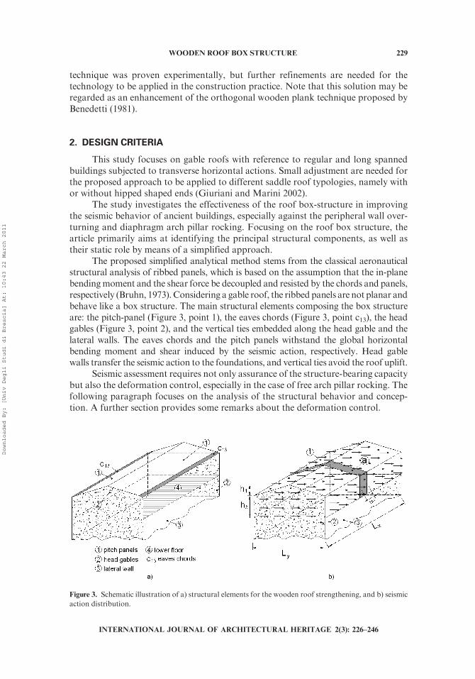
The proposed simplified analytical method stems from the classical aeronauticalstructural analysis of ribbed panels, which is based on the assumption that the in-planebendingmoment and the shear force be decoupled and resisted by the chords and panels,respectively (Bruhn, 1973). Considering a gable roof, the ribbed panels are not planar andbehave like a box structure. The main structural elements composing the box structureare: the pitch-panel (Figure 3, point 1), the eaves chords (Figure 3, point c13), the headgables (Figure 3, point 2), and the vertical ties embedded along the head gable and thelateral walls. The eaves chords and the pitch panels withstand the global horizontalbending moment and shear induced by the seismic action, respectively. Head gablewalls transfer the seismic action to the foundations, and vertical ties avoid the roof uplift.
Seismic assessment requires not only assurance of the structure-bearing capacitybut also the deformation control, especially in the case of free arch pillar rocking. Thefollowing paragraph focuses on the analysis of the structural behavior and concep-tion. A further section provides some remarks about the deformation control.
Figure 3. Schematic illustration of a) structural elements for the wooden roof strengthening, and b) seismic
action distribution.
WOODEN ROOF BOX STRUCTURE 229
INTERNATIONAL JOURNAL OF ARCHITECTURAL HERITAGE 2(3): 226–246
Downloaded By: [Univ Degli Studi di Brescia] At: 10:43 22 March 2011

2.1. Box Structure Behavior and Resistance
The design of the roof box structure is based on the idea that the horizontalseismic actions of both lateral walls, the diaphragm-arches, and the roof are trans-ferred by the roof box structure to the shear resisting head walls. Vertical loads are notconsidered because they are supposed to be supported by other structural systems,such as wooden trusses and ridge and wooden principal beams.
The pitch rafter-to-wall as well as the rafter-to-rafter constraints along the roofridge are modeled as hinged. The same conservative assumption is made for theperimeter wall footings. Furthermore, the lower floor (Figure 3, point 4), the headshear walls and the head gables (Figure 3, point 2) are assumed to behave like in-planerigid diaphragms.
In this scenario, in order to study the structure behavior, a two-step approach isaddressed. In the first step vertical and horizontal idealized additional constraints areintroduced along the roof ridgeline. In the second step these provisional constraintsare removed and their reaction forces are backed out. In the first step, the unit-widthstripe (Figure 3a), with additional vertical and horizontal constraints, undergoingseismic actions p1 and p3, behaves like a frame (Figure 4a). Each element is subjectedto axial force, bendingmoment and shear, which can be easily evaluated. Note that thewall elements resist the axial forces and bending moment by developing a sort ofnatural arch, whose resistance depends on the wall thickness and on the verticalconfinement provided by the vertical loads.
In this phase, significant uplifting vertical force per unit length nA arises alongthe top lateral wall, which is equal to:
nA ¼ p1l12h1 þ p3h3h1ð ÞLy � g�1l12=2 ð1Þ
where g1* is the roof dead load per unit area, which is generally conservatively reduced
to account for possible vertical load reduction induced by the vertical component ofthe seismic acceleration.
r
A Ba
1yf1y
p1
p3
h
Ly
l12
h3
1z
y
r1z
5
4 2
1
3 = –r1y
g1
p h3
23 nA
p h3
23 nA
r1y
r1z
4 2
3
g1
g1
* *
*
Figure 4. Illustration of frame-action.
230 E. GIURIANI AND A. MARINI
INTERNATIONAL JOURNAL OF ARCHITECTURAL HERITAGE 2(3): 226–246
Downloaded By: [Univ Degli Studi di Brescia] At: 10:43 22 March 2011
When nA is positive, the tensile forces must be balanced by the wall self-weight,through anchored bars, suitably embedded and distributed along the crowningmasonries.
Shear forces vA are transferred by the lateral walls to the roof box structure.Shear forces are equal to:
vA ¼ p3h3=2 ð2Þ
In order to guarantee shear transferring between the crowning masonries and the boxstructure, suitable connections must be adopted.
In the second step, the additional ridge constraint reactions (r1y and r1z) arebacked out with forces of equal intensity and opposite sign (f1y¼�r1y, f1z¼�r1z). Theridge vertical reaction f1z is sustained by the ridge beam. Note that in case of symme-try, f1z is only due to the dead loads g1
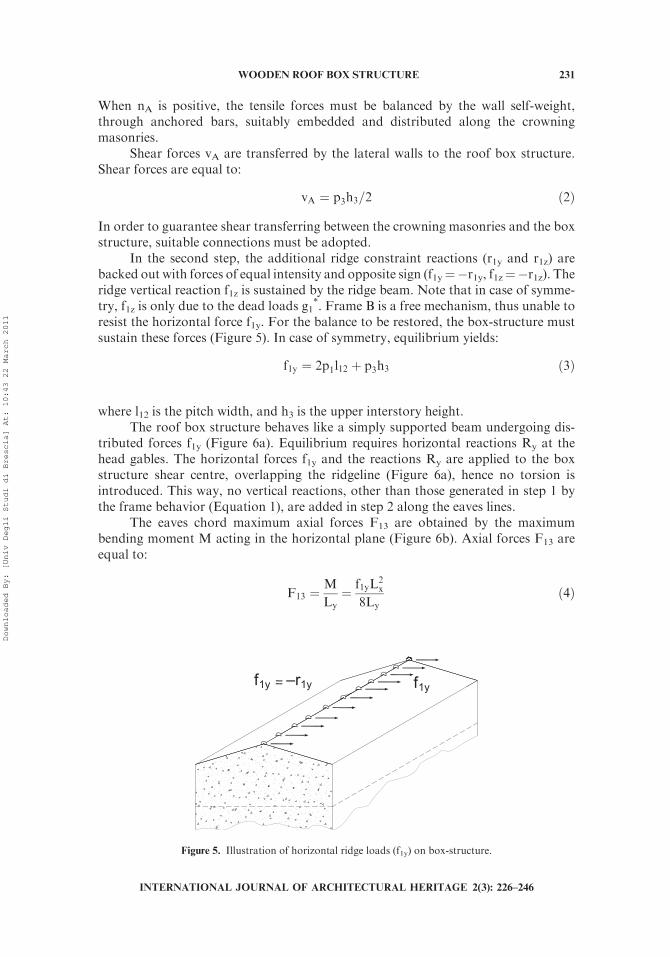
*. Frame B is a free mechanism, thus unable toresist the horizontal force f1y. For the balance to be restored, the box-structure mustsustain these forces (Figure 5). In case of symmetry, equilibrium yields:
f1y ¼ 2p1l12 þ p3h3 ð3Þ
where l12 is the pitch width, and h3 is the upper interstory height.The roof box structure behaves like a simply supported beam undergoing dis-
tributed forces f1y (Figure 6a). Equilibrium requires horizontal reactions Ry at thehead gables. The horizontal forces f1y and the reactions Ry are applied to the boxstructure shear centre, overlapping the ridgeline (Figure 6a), hence no torsion isintroduced. This way, no vertical reactions, other than those generated in step 1 bythe frame behavior (Equation 1), are added in step 2 along the eaves lines.
The eaves chord maximum axial forces F13 are obtained by the maximumbending moment M acting in the horizontal plane (Figure 6b). Axial forces F13 areequal to:
F13 ¼M
Ly¼ f1yL
2x
8Lyð4Þ
f1yf1y –r1y
Figure 5. Illustration of horizontal ridge loads (f1y) on box-structure.
WOODEN ROOF BOX STRUCTURE 231
INTERNATIONAL JOURNAL OF ARCHITECTURAL HERITAGE 2(3): 226–246
Downloaded By: [Univ Degli Studi di Brescia] At: 10:43 22 March 2011
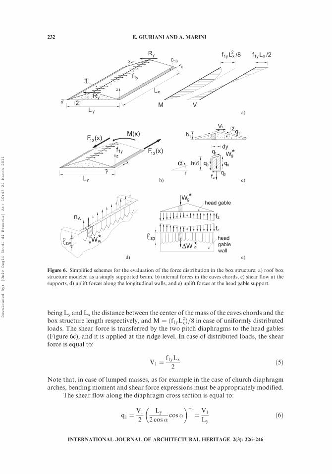
being Ly and Lx the distance between the center of the mass of the eaves chords and thebox structure length respectively, and M ¼ ðf1yL2
xÞ=8 in case of uniformly distributedloads. The shear force is transferred by the two pitch diaphragms to the head gables(Figure 6c), and it is applied at the ridge level. In case of distributed loads, the shearforce is equal to:
V1 ¼f1yLx
2ð5Þ
Note that, in case of lumped masses, as for example in the case of church diaphragmarches, bending moment and shear force expressions must be appropriately modified.
The shear flow along the diaphragm cross section is equal to:
q1 ¼V1
2
Ly
2 cos�cos�
� ��1¼ V1
Lyð6Þ
2
c
Ly
z
M
x
V
L1
x 13
y
x
f1y
R
Ry
y f1y xL /82 f1y xL /2
a)
Ly
y
F (x)13
F (x)13M(x)
xzf1y
b)
qV
1
1
h1
2
(y)
q1
q0hαq0
q0
Wg
dy
fz
*
c)
nA
Wwzw*
d)
Wg
fz
zg
fz
ΔW g
head gable
headgablewall
*
*e)
Figure 6. Simplified schemes for the evaluation of the force distribution in the box structure: a) roof box
structure modeled as a simply supported beam, b) internal forces in the eaves chords, c) shear flow at the
supports, d) uplift forces along the longitudinal walls, and e) uplift forces at the head gable support.
232 E. GIURIANI AND A. MARINI
INTERNATIONAL JOURNAL OF ARCHITECTURAL HERITAGE 2(3): 226–246
Downloaded By: [Univ Degli Studi di Brescia] At: 10:43 22 March 2011
The inclined shear flow q1 must be balanced by both horizontal shear flow q0 andvertical forces per unit length fz (Figure 6c). Equilibrium yields:
qo ¼q1
cos�
� �cos� ¼ q1
fz ¼ 2qo tan�� w�g
ð7Þ
where a is the roof pitch slope; w*g is the effective confining vertical loadprovided by the head gable weight per unit length, which can be possiblyreduced by the vertical component of the seismic acceleration, according to theassumption adopted in Equation 1. Note that forces per unit length fz vary alongthe y-axis following the variation of wg (Figure 6c), and are tensile forces alonghalf of the head gable.
2.2. Structure Proportioning
The proposed box structure proportioning aims at guaranteeing the elasticbehavior throughout the design seismic event. Nevertheless, the ductile behavior ofthe nailed connections, which are recognized as the weakest link of the structure,ensures a ductility resource at the ultimate limit state.
The eaves chords are designed to resist the axial forces F13 (Equation 4). In thecase of plywood pitch diaphragms, the eaves chords are over-proportioned to ensuretheir elastic behavior up to the structure collapse. To this end a conservative value forthe steel design resistance should be preferably chosen. Steel design resistance can beset equal to one third of the yielding strength. Furthermore, in order to avoid eaveschord buckling, suitable confining screws in addition to the nails must be adopted.
The pitch panel thickness, the panel mutual connection, as well as the diaphragmconnections to both the head gables and the eaves chords are proportioned to resist themaximum shear flow q1 (Equation 6).
The nail spacing �xn along every steel flange, both in x and y directions, is equalto:
�xn ¼Vn
q1ð8Þ
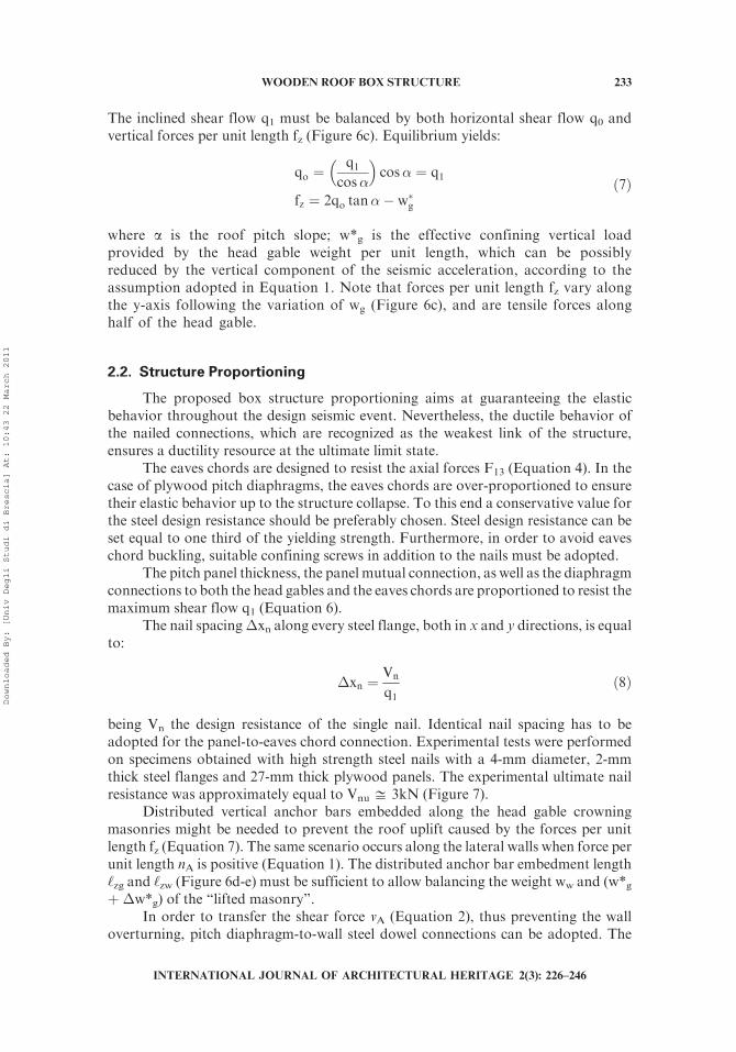
being Vn the design resistance of the single nail. Identical nail spacing has to beadopted for the panel-to-eaves chord connection. Experimental tests were performedon specimens obtained with high strength steel nails with a 4-mm diameter, 2-mmthick steel flanges and 27-mm thick plywood panels. The experimental ultimate nailresistance was approximately equal to Vnu % 3kN (Figure 7).
Distributed vertical anchor bars embedded along the head gable crowningmasonries might be needed to prevent the roof uplift caused by the forces per unitlength fz (Equation 7). The same scenario occurs along the lateral walls when force perunit length nA is positive (Equation 1). The distributed anchor bar embedment length‘zg and ‘zw (Figure 6d-e) must be sufficient to allow balancing the weight ww and (w*gþ �w*g) of the ‘‘lifted masonry’’.
In order to transfer the shear force vA (Equation 2), thus preventing the walloverturning, pitch diaphragm-to-wall steel dowel connections can be adopted. The
WOODEN ROOF BOX STRUCTURE 233
INTERNATIONAL JOURNAL OF ARCHITECTURAL HERITAGE 2(3): 226–246
Downloaded By: [Univ Degli Studi di Brescia] At: 10:43 22 March 2011
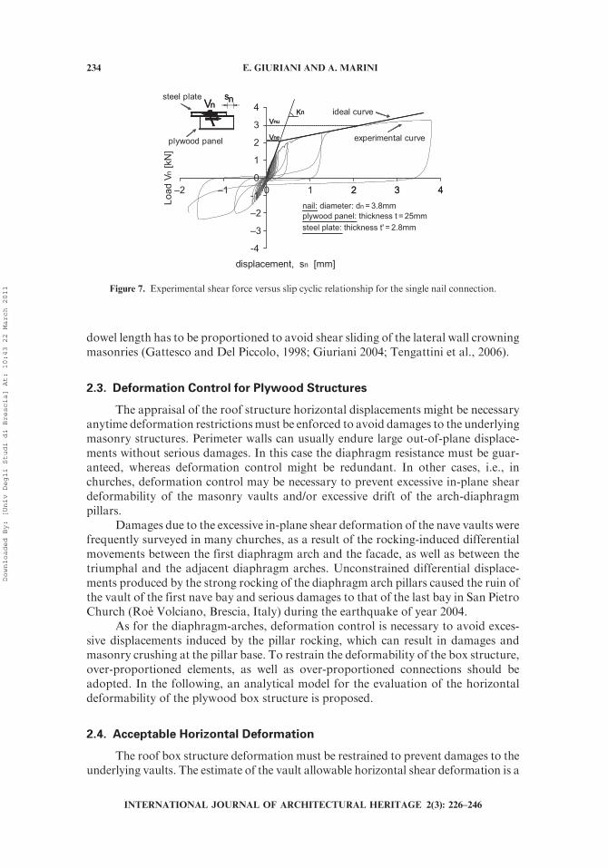
dowel length has to be proportioned to avoid shear sliding of the lateral wall crowningmasonries (Gattesco and Del Piccolo, 1998; Giuriani 2004; Tengattini et al., 2006).
2.3. Deformation Control for Plywood Structures
The appraisal of the roof structure horizontal displacements might be necessaryanytime deformation restrictionsmust be enforced to avoid damages to the underlyingmasonry structures. Perimeter walls can usually endure large out-of-plane displace-ments without serious damages. In this case the diaphragm resistance must be guar-anteed, whereas deformation control might be redundant. In other cases, i.e., inchurches, deformation control may be necessary to prevent excessive in-plane sheardeformability of the masonry vaults and/or excessive drift of the arch-diaphragmpillars.
Damages due to the excessive in-plane shear deformation of the nave vaults werefrequently surveyed in many churches, as a result of the rocking-induced differentialmovements between the first diaphragm arch and the facade, as well as between thetriumphal and the adjacent diaphragm arches. Unconstrained differential displace-ments produced by the strong rocking of the diaphragm arch pillars caused the ruin ofthe vault of the first nave bay and serious damages to that of the last bay in San PietroChurch (Roe Volciano, Brescia, Italy) during the earthquake of year 2004.
As for the diaphragm-arches, deformation control is necessary to avoid exces-sive displacements induced by the pillar rocking, which can result in damages andmasonry crushing at the pillar base. To restrain the deformability of the box structure,over-proportioned elements, as well as over-proportioned connections should beadopted. In the following, an analytical model for the evaluation of the horizontaldeformability of the plywood box structure is proposed.
2.4. Acceptable Horizontal Deformation
The roof box structure deformation must be restrained to prevent damages to theunderlying vaults. The estimate of the vault allowable horizontal shear deformation is a
-4
–3
–2
-1
0
1
2
3
4
–2 –1 0 1 2 3 4
displacement, sn [mm]
Load
Vn
[kN
]
nail: diameter: dn = 3.8mmplywood panel: thickness t = 25mm
ideal curve
experimental curve
Kn
steel plate
plywood panel
Vnu
Vne
Vn ns
2 3 4
steel plate: thickness t' = 2.8mm
KnVnu
Vne
Vn ns
Figure 7. Experimental shear force versus slip cyclic relationship for the single nail connection.
234 E. GIURIANI AND A. MARINI
INTERNATIONAL JOURNAL OF ARCHITECTURAL HERITAGE 2(3): 226–246
Downloaded By: [Univ Degli Studi di Brescia] At: 10:43 22 March 2011
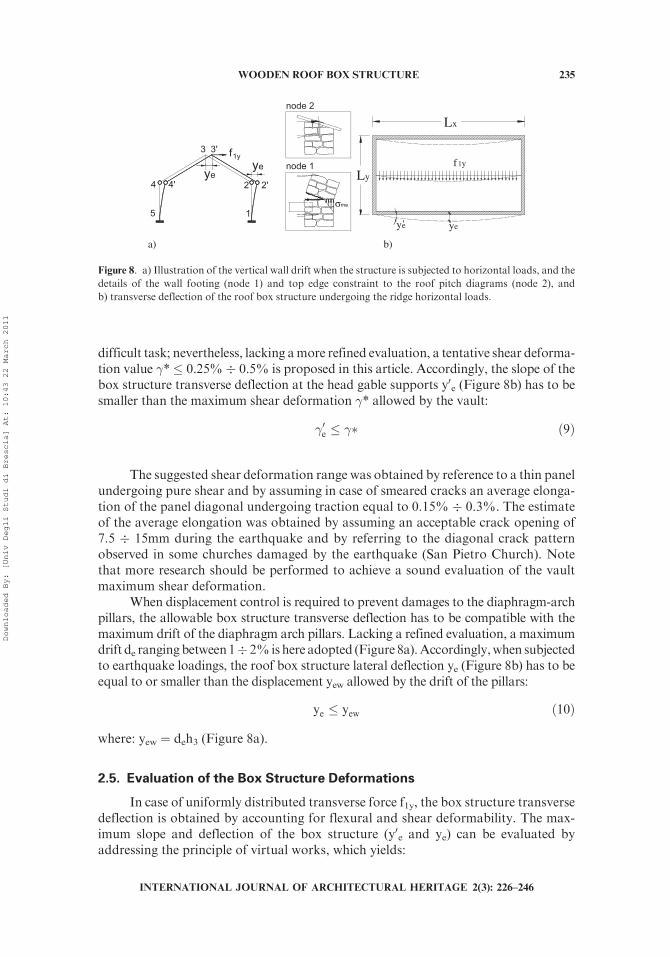
difficult task; nevertheless, lacking amore refined evaluation, a tentative shear deforma-tion value �*� 0.25%� 0.5% is proposed in this article. Accordingly, the slope of thebox structure transverse deflection at the head gable supports y0e (Figure 8b) has to besmaller than the maximum shear deformation �* allowed by the vault:
�0e � �� ð9Þ
The suggested shear deformation range was obtained by reference to a thin panelundergoing pure shear and by assuming in case of smeared cracks an average elonga-tion of the panel diagonal undergoing traction equal to 0.15% � 0.3%. The estimateof the average elongation was obtained by assuming an acceptable crack opening of7.5 � 15mm during the earthquake and by referring to the diagonal crack patternobserved in some churches damaged by the earthquake (San Pietro Church). Notethat more research should be performed to achieve a sound evaluation of the vaultmaximum shear deformation.
When displacement control is required to prevent damages to the diaphragm-archpillars, the allowable box structure transverse deflection has to be compatible with themaximum drift of the diaphragm arch pillars. Lacking a refined evaluation, a maximumdrift de rangingbetween1� 2%ishere adopted (Figure 8a).Accordingly,when subjectedto earthquake loadings, the roof box structure lateral deflection ye (Figure 8b) has to beequal to or smaller than the displacement yew allowed by the drift of the pillars:
ye � yew ð10Þ
where: yew ¼ deh3 (Figure 8a).
2.5. Evaluation of the Box Structure Deformations
In case of uniformly distributed transverse force f1y, the box structure transversedeflection is obtained by accounting for flexural and shear deformability. The max-imum slope and deflection of the box structure (y0e and ye) can be evaluated byaddressing the principle of virtual works, which yields:
f1y
1
2
3
4
5
2'
3'
4'ye
ye
σme
node 1
node 2
ye
Ly
Lx
'ye
f1y
a) b)
Figure 8. a) Illustration of the vertical wall drift when the structure is subjected to horizontal loads, and the
details of the wall footing (node 1) and top edge constraint to the roof pitch diagrams (node 2), and
b) transverse deflection of the roof box structure undergoing the ridge horizontal loads.
WOODEN ROOF BOX STRUCTURE 235
INTERNATIONAL JOURNAL OF ARCHITECTURAL HERITAGE 2(3): 226–246
Downloaded By: [Univ Degli Studi di Brescia] At: 10:43 22 March 2011
ye ¼5
384
f1yL4x
E�wJidþ f1yL
2x
8G�wLy t cos�
� �ð11Þ
y0e ¼ f1y1
24
L3x
E�wJidþ Lx
2
1
Lyt
1
G�w
� �ð12Þ
where E*w and G*w are the pitch diaphragm equivalent Young and shear moduli,which account for the shear deformability of the panel nail connections; Jid is thesecond moment of area of the ideal transformed cross section; t is the plywood panelthickness. Chords and pitch diaphragm stiffness is assumed to be constant along the x-axis.
The deformability of the box structure is strongly affected by the shear slip of thenailed connections. In order to account, in a simple fashion, for the reduction of thebending and shear stiffness caused by the panel-to-panel nailed connections, equiva-lent Young (E*w) and shear (G*w) moduli are adopted in Equation10 and 11.
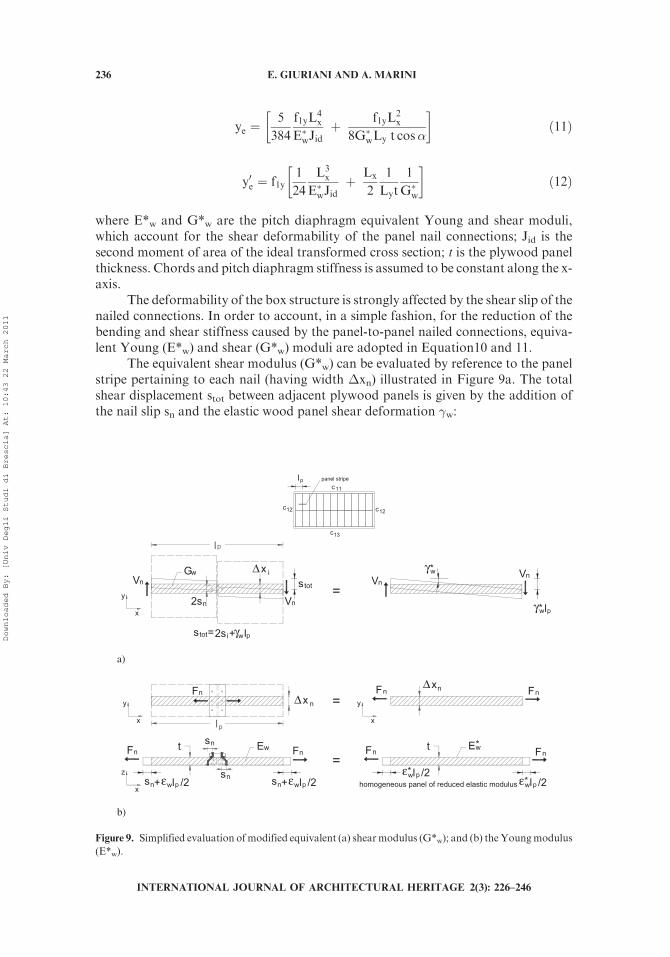
The equivalent shear modulus (G*w) can be evaluated by reference to the panelstripe pertaining to each nail (having width �xn) illustrated in Figure 9a. The totalshear displacement stot between adjacent plywood panels is given by the addition ofthe nail slip sn and the elastic wood panel shear deformation �w:
c12
c13
c 11
c12
l p panel stripe
l p
pγw2s + li
Vn
2sn
Δx i
pγw
Gw
*x
ystot
s =tot
Vn
γw* Vn
Vn
a)
FnΔx
l p
n
+ l /2 pεwn
t
x
y
Ew Fn Fn
l /2 pεw* l /2 pεw*
Fn FnΔxn
Ew*
x
y
homogeneous panel of reduced elastic modulusx
z
Fn Fn sn
sn s + l /2 pεwn s
t
b)
Figure 9. Simplified evaluation ofmodified equivalent (a) shearmodulus (G*w); and (b) theYoungmodulus
(E*w).
236 E. GIURIANI AND A. MARINI
INTERNATIONAL JOURNAL OF ARCHITECTURAL HERITAGE 2(3): 226–246
Downloaded By: [Univ Degli Studi di Brescia] At: 10:43 22 March 2011
stot ¼ 2sn þ �wlp ð13Þ
being lp the panel width.The connection shear slip sn is given by the elastic relationship:
sn ¼ Vn=kn ð14Þ
where kn is the single nail shear stiffness (Figure 7, branch sn , sne), which can beobtained either experimentally, or by reference to formulations provided by theliterature ().
The ideal shear deformation �*w is:
��w ¼stotlp
ð15Þ
Being tw ¼ Vn / Awn and �w ¼ Vn / (Awn Gw), by substituting Equation 12 and 13 inEquation 14, the ideal shear modulus G*w ¼ tw / �*w becomes as follows:
G�w ¼knlp
2Awn þknlpGw
ð16Þ
where Awn¼�xnt is the panel stripe cross section area, �xn is the nail spacing and t isthe panel thickness.
The equivalent Young modulus (E*w) is evaluated by considering the unit panelstripe in Figure 9b. The total displacement caused by the tensile force (Fn) across thepanel stripe is equal to:
2sn þ ewlp ¼ e�wlp ¼Fn
AwE�w
lp ð17Þ
being ew and e*w the plywood panel and the equivalent panel axial strains,respectively.
By rearranging Equation16, the equivalent Young modulus (E*w) can beobtained:
E�w ¼knlp
2Awn þ knlpEw
ð18Þ
Note that the plywood deformability plays a significant role in the appraisal of theequivalent panel characteristics. By neglecting the panel deformability — i.e., bysetting Ew and Gw equal to infinity in Equation 15 and Equation 17, and by assumingordinary values of the geometric and mechanic properties (lp ¼ 1200 mm, Awn ¼ 50mm�27.5mm, Ew ¼ 5000 MPa, Gw ¼ 2500 MPa, kn ¼ 2700 N/mm) — a 25% over-estimate of the ideal Young modulus E*
w and a 50% overestimate of the shearmodulus G*
w are obtained.
WOODEN ROOF BOX STRUCTURE 237
INTERNATIONAL JOURNAL OF ARCHITECTURAL HERITAGE 2(3): 226–246
Downloaded By: [Univ Degli Studi di Brescia] At: 10:43 22 March 2011
3. CASE STUDY
The proposed simplified analytical formulation is applied to the design ofthe anti-seismic retrofit of a typical gable roof (Figure 5). Roof and crowningmasonry wall seismic loads are carried by the box structure, overlaying theexisting roof.
With reference toFigure 3, the following data are given:Lx¼ 30.0m;Ly¼ 10.0m;h1¼ 2.02 m; h3¼ 3.0 m; l12¼ 5.39 m; a¼ 22�. The roof pitch seismic action is set equalto 20%of the vertical load (g1¼ 3 kN/m2), thus p1¼ 0.6 kN/m2. The lateral wall seismicaction is equal to p3¼ 2 kN/m2, where a wall thickness sm¼ 0.5 m and a specific gravityload gm ¼ 20 kN/m3 are assumed.
The horizontal forces f1y applied along the box structure ridgeline (Equation 3)are equal to:
f1;y ¼ 2p1l12 þ p3h3 ¼ 12:5kN=m ð19Þ
The box structure maximum bending moment M and shear force V are equal to:
M ¼ f1yL2x
8¼ 140kNm V1 ¼
f1yLx
2¼ 187:5kN ð20Þ
The eaves chord axial forces F13 and cross section area yield as follows:
F13 ¼M
Ly¼ 140:6kN Ac13 ¼
F13
�s¼ 1125 mm2 ¼ 75� 20 mm2 ð21Þ
where a reduced value of the steel design resistance is adopted (ss @ 100 MPa) toprevent buckling.
In order to avoid the compressed chord uplift induced by instability,anchorages and screws fixing the chord to the wall and to the wood panels areneeded. The maximum anchorage spacing Dxa depends on the thickness of thechords. The adopted reduced steel stress value ss ¼ wfyd % 100 MPa yields aninstability reduction factor w ¼ 0.35 (for fyd ¼ 280 MPa). This reduction factorcorresponds to a slenderness approximately equal to l% 120. The effective length isequal to:
lo ¼ �tcffiffiffiffiffi12p ¼ 120 � 20ffiffiffiffiffi
12p ffi 0:7 m ð22Þ
being tc ¼ 20 mm the thickness of the eaves chord steel plate.The maximum anchorage spacing Dxa, yields as follows:
�xa ¼ 2lo ¼ 1:4 m lo ¼ �tcffiffiffiffiffi12p ¼ 120 � 20ffiffiffiffiffi
12p ffi 0:7 m ð23Þ
The maximum shear flow q1 and the nailed connection spacing Dxn are respectivelyequal to:
q1 ¼V1
Ly¼ 18:75 kN=m �xn ¼
Vn
q1¼ 53 mm! 50 mm ð24Þ
238 E. GIURIANI AND A. MARINI
INTERNATIONAL JOURNAL OF ARCHITECTURAL HERITAGE 2(3): 226–246
Downloaded By: [Univ Degli Studi di Brescia] At: 10:43 22 March 2011
where high strength steel nails of 4 mm diameter with a resistance Vn ¼ 1.0 kN areadopted. Similar nailed connections are used to fix the wood panel to the eaveschords.
Pitch diaphragms undergoing the shear flow q1 are made of commercial ply-wood panels having a thickness t ¼ 27.5 mm. The maximum shear stress is equal to:
tw ¼q1t¼ 0:68MPa ð25Þ
The pitch diaphragm-to-head gable dowel connections are subjected to the shearflow q1, thus the dowel spacing is equal to:
�yd ¼Vdn
q1¼ 6:0
18:75¼ 0:32 m ð26Þ
being Vdn ¼ 6 kN the plywood panel-to-masonry wall connection design resistance,corresponding to 1/2 of the smallest ultimate resistance recorded in the experimentaltests on a 16 mm diameter steel stud (Gattesco and Del Piccolo, 1998, Giuriani, 2004;Tengattini et al., 2006).
The maximum embedment length lzg of the vertical anchorages placed along thehead gable is equal to (Figure 6e):
lzg ¼fz
sm�m¼ 15:15
0:5 � 20 ¼ 1:5 m ð27Þ
being fz ¼ 2qo tan a ¼ 2.0 � 18.75 � 0.4 ¼ 15.15kN/m, where wg is conservativelyneglected.
The uplift distributed forces nA induced by the frame behavior along the lateralwalls are equal to:
nA ¼ ðp1l12h1 þ p3h3h1Þ=Ly � g�1l12=2 ¼ �3:5kN=m ð28Þ
where the dead loads are conservatively reduced to 70% (g*1 ¼ 0.7g1 ¼ 2kN/m2) toaccount for possible vertical load reduction induced by the seismic accelerationvertical component. Note that in this case no anchorages are needed, provided thatnA is negative, thus box structure uplift is inhibited.
The transverse shear force vA transferred by the lateral walls to the box structureis equal to:
vA ¼ p3h3=2 ¼ 3kN=m ð29Þ
To allow shear transferring, wall-to-pitch diaphragm dowel connections arerequired. The dowel connection spacing is equal to:
�xd ¼ �Vdn=vA ¼ 3=3 ¼ 1 m ð30Þ
where a reduced value of the dowel resistance is adopted to account for the reducedout-of-plane shear resistance of the top wall (Vdn ¼ 3kN, corresponding to 1/4 of thesmallest ultimate resistance recorded in the experimental tests on a 16-mm diameterstud, having an embedment length of 0.3 � 0.5m; Tengattini et al., 2006). Note that
WOODEN ROOF BOX STRUCTURE 239
INTERNATIONAL JOURNAL OF ARCHITECTURAL HERITAGE 2(3): 226–246
Downloaded By: [Univ Degli Studi di Brescia] At: 10:43 22 March 2011
this distance is smaller than spacing Dxa required to avoid eaves chord buckling.Therefore, by enforcing this spacing to the connections along the lateral walls,instability is inhibited.
As for the structure deformation, by setting Ew ¼ 5000 MPa and Gw ¼ 2500MPa, Equation 15 and Equation 17 yield G*
w ¼ 800 MPa and E*w ¼ 953 MPa,
respectively. The maximum in-plane pitch diaphragm displacement is equal to(Equation 10):
ye ¼5
384
f1yL4x
E�wJidþ f1yL
2x
8G�wLYt cos�¼ 7:3þ 13:7 ¼ 21:0 mm ð31Þ
where Jid ¼ 1.88�1013 mm4.The deflection assessment reads as follows:
ye ¼ 21:0 mm � deh3 ¼ 0:01 � 3000 ¼ 30 mm ð32Þ
The requirement of Equation 9 is therefore largely satisfied.The slope of the box structure deflection at the head gable supports y0e is equal
to:
y0e ¼ f1y1
24
L3x
E�wJidþ Lx
2
1
Lyt
1
G�w
� �¼ 2:25 � 10�3 � y0ew ð33Þ
This value satisfies the requirement of Equation 8.
3.1. Numerical Assessment
The static behavior of the gable roof box structure analyzed in the case study,which was proportioned and studied by reference to the simplified method, wascompared with the results of linear elastic finite element analyses. Equivalent statictransverse seismic action was considered. In the analyses, only the roof was modeled;the lateral masonry walls were represented by vertical hinged beam elements, inhibit-ing any vertical displacement of the roof along the eaves lines, but allowing horizontaltransverse displacements and rotations. The head gables were modeled as in-planerigid diaphragms, allowing out-of the plane displacements and rotations.
Two different mesh types (A, B in the following) were analyzed (Giuriani et al.,2002): in mesh A (Figure 10a), all structural elements composing the existing woodenroof and the box structure were modeled. Wooden rafters and steel eaves chords weremodeled by means of beam elements, whereas pitch web panels were modeled bymeans of plate elements. Wooden rafters were hinged at both ends. The deformabilityof the nailed shear connections between the pitch web panels was considered byintroducing along every connection special plate elements having a reduced equivalentelastic E*
w and shear moduli G*w. Reduced stiffness properties were obtained by
reference to Equations 15 and 17. Geometric and mechanical characteristics of eachelement are those illustrated in Table 1a. Load distribution is shown in Figure 10a.
In mesh B (Figure 10b) the roof box structure was modeled without the woodenrafters. Only the ridge horizontal load f1y was considered. The box structure wasmodeled as in mesh A. Geometric and mechanical characteristics of each element are
240 E. GIURIANI AND A. MARINI
INTERNATIONAL JOURNAL OF ARCHITECTURAL HERITAGE 2(3): 226–246
Downloaded By: [Univ Degli Studi di Brescia] At: 10:43 22 March 2011
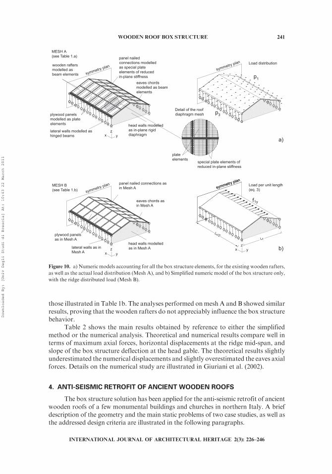
those illustrated in Table 1b. The analyses performed onmesh A and B showed similarresults, proving that the wooden rafters do not appreciably influence the box structurebehavior.
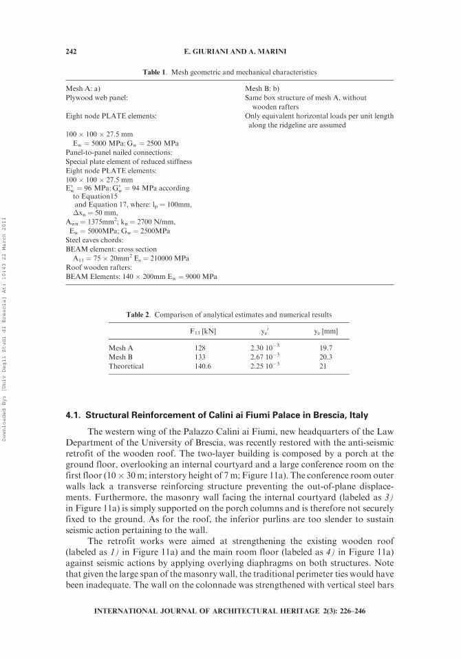
Table 2 shows the main results obtained by reference to either the simplifiedmethod or the numerical analysis. Theoretical and numerical results compare well interms of maximum axial forces, horizontal displacements at the ridge mid-span, andslope of the box structure deflection at the head gable. The theoretical results slightlyunderestimated the numerical displacements and slightly overestimated the eaves axialforces. Details on the numerical study are illustrated in Giuriani et al. (2002).
4. ANTI-SEISMIC RETROFIT OF ANCIENT WOODEN ROOFS
The box structure solution has been applied for the anti-seismic retrofit of ancientwooden roofs of a few monumental buildings and churches in northern Italy. A briefdescription of the geometry and the main static problems of two case studies, as well asthe addressed design criteria are illustrated in the following paragraphs.
symmetry plan
lateral walls modelled ashinged beams
plywood panelsmodelled as plateelements
eaves chordsmodelled as beamelements
head walls modelledas in-plane rigiddiaphragmx y
z
panel nailedconnections modelledas special plateelements of reducedin-plane stiffness
wooden raftersmodelled asbeam elements
(see Table 1.a)
symmetry plan
MESH B(see Table 1.b) symmetry plan
lateral walls as inMesh A
plywood panelsas in Mesh A
eaves chords asin Mesh A
head walls modelledas in Mesh A
x yz
panel nailed connections asin Mesh A symmetry plan
symmetry plan
x yz
Lx/2Ly
p1
p3
f1y
special plate elements ofreduced in-plane stiffness
plateelements
Detail of the roofdiaphragm mesh
Load distribution
Load per unit length(eq. 3)
a)
b)
Figure 10. a) Numeric models accounting for all the box structure elements, for the existing wooden rafters,
as well as the actual load distribution (Mesh A), and b) Simplified numeric model of the box structure only,
with the ridge distributed load (Mesh B).
WOODEN ROOF BOX STRUCTURE 241
INTERNATIONAL JOURNAL OF ARCHITECTURAL HERITAGE 2(3): 226–246
Downloaded By: [Univ Degli Studi di Brescia] At: 10:43 22 March 2011
4.1. Structural Reinforcement of Calini ai Fiumi Palace in Brescia, Italy
The western wing of the Palazzo Calini ai Fiumi, new headquarters of the LawDepartment of the University of Brescia, was recently restored with the anti-seismicretrofit of the wooden roof. The two-layer building is composed by a porch at theground floor, overlooking an internal courtyard and a large conference room on thefirst floor (10� 30m; interstory height of 7m; Figure 11a). The conference room outerwalls lack a transverse reinforcing structure preventing the out-of-plane displace-ments. Furthermore, the masonry wall facing the internal courtyard (labeled as 3)in Figure 11a) is simply supported on the porch columns and is therefore not securelyfixed to the ground. As for the roof, the inferior purlins are too slender to sustainseismic action pertaining to the wall.
The retrofit works were aimed at strengthening the existing wooden roof(labeled as 1) in Figure 11a) and the main room floor (labeled as 4) in Figure 11a)against seismic actions by applying overlying diaphragms on both structures. Notethat given the large span of the masonry wall, the traditional perimeter ties would havebeen inadequate. The wall on the colonnade was strengthened with vertical steel bars
Table 2. Comparison of analytical estimates and numerical results
F13 [kN] ye0 ye [mm]
Mesh A 128 2.30 10�3 19.7
Mesh B 133 2.67 10�3 20.3
Theoretical 140.6 2.25 10�3 21
Table 1. Mesh geometric and mechanical characteristics
Mesh A: a) Mesh B: b)
Plywood web panel: Same box structure of mesh A, without
wooden rafters
Eight node PLATE elements: Only equivalent horizontal loads per unit length
along the ridgeline are assumed
100 � 100 � 27.5 mm
Ew ¼ 5000 MPa;Gw ¼ 2500 MPa
Panel-to-panel nailed connections:
Special plate element of reduced stiffness
Eight node PLATE elements:
100 � 100 � 27.5 mmE�w ¼ 96 MPa;G�w ¼ 94 MPa accordingto Equation15and Equation 17, where: lp ¼ 100mm,�xn ¼ 50 mm,
Awn ¼ 1375mm2; kn ¼ 2700 N/mm,
Ew ¼ 5000MPa; Gw ¼ 2500MPa
Steel eaves chords:
BEAM element: cross section
A11 ¼ 75 � 20mm2 Es ¼ 210000 MPa
Roof wooden rafters:
BEAM Elements: 140 � 200mm Ew ¼ 9000 MPa
242 E. GIURIANI AND A. MARINI
INTERNATIONAL JOURNAL OF ARCHITECTURAL HERITAGE 2(3): 226–246
Downloaded By: [Univ Degli Studi di Brescia] At: 10:43 22 March 2011

(labeled as a) in Figure 11a) built in the wall between the openings. This way themasonry was provided with sufficient strength and stiffness to transfer the seismicactions to the resisting diaphragm of both the main room floor and the saddle roof.
The floor and the roof were designed to resist and transfer both their seismicactions and those pertaining to the lateral walls to the shear resisting head gables(labeled as 2) in Figure 11a). The floor diaphragm was obtained by casting a thinconcrete slab on top of the existing wooden floor, whereas the pitch diaphragms weremade of plywood panels connected by thin steel flanges nailed to the panels.Figure 11b shows a perspective view of the anti-seismic plywood roof box structureupon completion.
4.2. Structural Reinforcement of San Pietro Church in Roe Volciano,Brescia, Italy
San Pietro church (XIV century) is a single nave church, with lateral chapelscovered by a gable roof (Figure 12a). The church has been largely remodeled andrestored through the years to meet the new religious needs, but most of all to repair thesevere damages caused by recurrent earthquakes, in the Benaco area.
a) b)
Figure 12. Photographs of the San Pietro Church in Roe Vociano, Brescia, Italy: a) prospective view of the
southern front; and b) damage of the barrel vault of the first main nave bay.
2
4
a
1
3
a) b)
Figure 11. Palazzo Calini ai Fiumi: a) simplified scheme of the structure; b) photograph of the anti-seismic
plywood roof box structure.
WOODEN ROOF BOX STRUCTURE 243
INTERNATIONAL JOURNAL OF ARCHITECTURAL HERITAGE 2(3): 226–246
Downloaded By: [Univ Degli Studi di Brescia] At: 10:43 22 March 2011
A series of four transverse arches divides the nave into 5 bays. The nave iscovered by 50-mm, single-leaf, masonry barrel vaults. The existing gable roof, lackingany anti-seismic characteristics, is made of transverse rafters carried by four beamsand the ridge beam. The last strong seismic event hitting northern Italy in 2004 causedthe global ruin of the barrel vault close to the facade (Figure 12b), and the extendeddamage of the vault next to the triumphal arch. The damage was mainly caused by theexcessive in-plane shear deformation induced by the unconstrained differential dis-placement of the facade and of the neighboring diaphragm arch. The differentialdisplacements were the result of the pronounced difference in the stiffness of thevertical bearing structures.
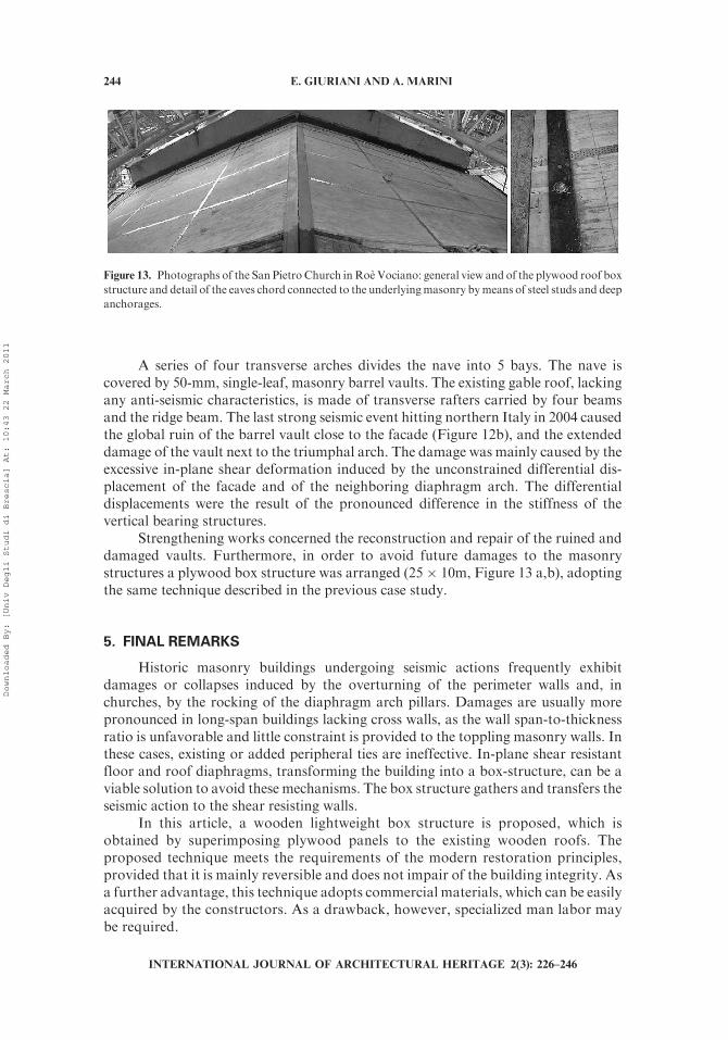
Strengthening works concerned the reconstruction and repair of the ruined anddamaged vaults. Furthermore, in order to avoid future damages to the masonrystructures a plywood box structure was arranged (25 � 10m, Figure 13 a,b), adoptingthe same technique described in the previous case study.
5. FINAL REMARKS
Historic masonry buildings undergoing seismic actions frequently exhibitdamages or collapses induced by the overturning of the perimeter walls and, inchurches, by the rocking of the diaphragm arch pillars. Damages are usually morepronounced in long-span buildings lacking cross walls, as the wall span-to-thicknessratio is unfavorable and little constraint is provided to the toppling masonry walls. Inthese cases, existing or added peripheral ties are ineffective. In-plane shear resistantfloor and roof diaphragms, transforming the building into a box-structure, can be aviable solution to avoid these mechanisms. The box structure gathers and transfers theseismic action to the shear resisting walls.
In this article, a wooden lightweight box structure is proposed, which isobtained by superimposing plywood panels to the existing wooden roofs. Theproposed technique meets the requirements of the modern restoration principles,provided that it is mainly reversible and does not impair of the building integrity. Asa further advantage, this technique adopts commercial materials, which can be easilyacquired by the constructors. As a drawback, however, specialized man labor maybe required.
Figure 13. Photographs of the San Pietro Church inRoe Vociano: general view and of the plywood roof box
structure and detail of the eaves chord connected to the underlyingmasonry bymeans of steel studs and deep
anchorages.
244 E. GIURIANI AND A. MARINI
INTERNATIONAL JOURNAL OF ARCHITECTURAL HERITAGE 2(3): 226–246
Downloaded By: [Univ Degli Studi di Brescia] At: 10:43 22 March 2011
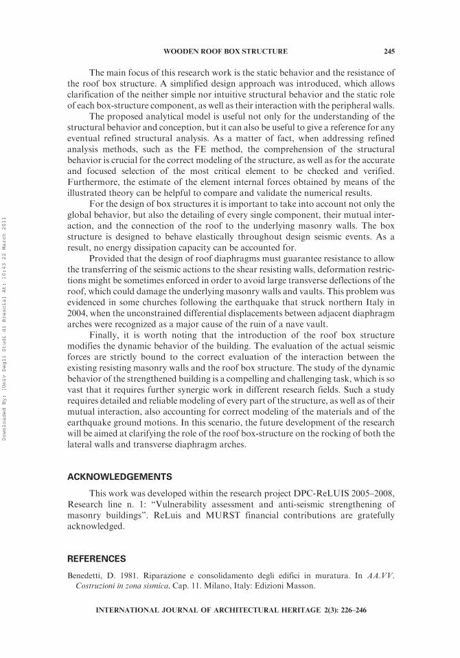
The main focus of this research work is the static behavior and the resistance ofthe roof box structure. A simplified design approach was introduced, which allowsclarification of the neither simple nor intuitive structural behavior and the static roleof each box-structure component, as well as their interaction with the peripheral walls.
The proposed analytical model is useful not only for the understanding of thestructural behavior and conception, but it can also be useful to give a reference for anyeventual refined structural analysis. As a matter of fact, when addressing refinedanalysis methods, such as the FE method, the comprehension of the structuralbehavior is crucial for the correct modeling of the structure, as well as for the accurateand focused selection of the most critical element to be checked and verified.Furthermore, the estimate of the element internal forces obtained by means of theillustrated theory can be helpful to compare and validate the numerical results.
For the design of box structures it is important to take into account not only theglobal behavior, but also the detailing of every single component, their mutual inter-action, and the connection of the roof to the underlying masonry walls. The boxstructure is designed to behave elastically throughout design seismic events. As aresult, no energy dissipation capacity can be accounted for.
Provided that the design of roof diaphragms must guarantee resistance to allowthe transferring of the seismic actions to the shear resisting walls, deformation restric-tions might be sometimes enforced in order to avoid large transverse deflections of theroof, which could damage the underlying masonry walls and vaults. This problem wasevidenced in some churches following the earthquake that struck northern Italy in2004, when the unconstrained differential displacements between adjacent diaphragmarches were recognized as a major cause of the ruin of a nave vault.
Finally, it is worth noting that the introduction of the roof box structuremodifies the dynamic behavior of the building. The evaluation of the actual seismicforces are strictly bound to the correct evaluation of the interaction between theexisting resisting masonry walls and the roof box structure. The study of the dynamicbehavior of the strengthened building is a compelling and challenging task, which is sovast that it requires further synergic work in different research fields. Such a studyrequires detailed and reliable modeling of every part of the structure, as well as of theirmutual interaction, also accounting for correct modeling of the materials and of theearthquake ground motions. In this scenario, the future development of the researchwill be aimed at clarifying the role of the roof box-structure on the rocking of both thelateral walls and transverse diaphragm arches.
ACKNOWLEDGEMENTS
This work was developed within the research project DPC-ReLUIS 2005–2008,Research line n. 1: ‘‘Vulnerability assessment and anti-seismic strengthening ofmasonry buildings’’. ReLuis and MURST financial contributions are gratefullyacknowledged.
REFERENCES
Benedetti, D. 1981. Riparazione e consolidamento degli edifici in muratura. In AA.VV.
Costruzioni in zona sismica, Cap. 11. Milano, Italy: Edizioni Masson.
WOODEN ROOF BOX STRUCTURE 245
INTERNATIONAL JOURNAL OF ARCHITECTURAL HERITAGE 2(3): 226–246
Downloaded By: [Univ Degli Studi di Brescia] At: 10:43 22 March 2011
Bruhn, E. F. 1973. Analysis and design of flight vehicle structures. Indianapolis, IN: JacobsPublishing Inc.
D’Ayala, D., and Speranza, E. 2002. An integrated procedure for the assessment of seismic
vulnerability of historic buildings [CD-ROM]. Proceedings of the 12th European Conferenceon Earthquake Engineering, paper n. 561 London, England: Elsevier Science.
De Benedectis, R., De Felice, G., and Giuffre, A. 1993. Restauro antisismico di un edificio. InSicurezza e conservazione dei centri storici: Il caso Ortigia, ed. Giuffre A. Bari, Italy: EditriceLaterza, 189–205.
Eurocode 5. 2005. European Committee for Standardization (CEN). UNI EN 1995:2005.Design of timber structures. Brussels.
Gattesco, N., and Del Piccolo, G. 1998. Shear transfer between concrete members and stonemasonry wall through driver dowels. European Earthquake Engineering, 1.
Giuriani, E., and Plizzari, G. 2000. Studio sperimentale sul comportamento dei solai in legno
rinforzati con lastra in acciaio per resistere alle azioni sismiche. V Workshop Italiano sulleCostruzioni Composte, Polermo, November 23–24, 2000, 277–292.
Giuriani, E., and Frangipane, A. 1993. Wood-to-concrete composite section for stiffening ofancient wooden beam floors. Atti del 1� Workshop Italiano sulle Strutture Composte, Trento,Italy, June 17–18, 1993. Trento, Italy: Universita degli studi di Trento.
Giuriani, E., and Marini, A. 2002. Coperture in legno antisismiche. Technical Report(6).Brescia, Italy: Universita degli Studi di Brescia, Dipartimento di Ingegneria Civile.
Giuriani E., Guilarte F., Marini A., and Tonioli A. 2002. Comportamento sismico delle
coperture in legno. Technical Report, (19). Brescia, Italy: Universita degli Studi di Brescia,Dipartimento di Ingegneria Civile.
Giuriani E., Marini A., and Plizzari G. 2005. Experimental behavior of stud connected woodenfloors undergoing seismic action. Restoration of Buildings and Monuments 11(1):3–24.
Giuriani, E. 2004. L’organizzazione degli impalcati per gli edifici storici. L’Edilizia. Speciale
Legno strutturale (134): 30–41.GriffithM. C.,MagenesG.,Melis G., and Picchi L. 2003. Evaluation of out-of-plane stability of
unreinforced masonry walls subjected to seismic excitation. Journal of EarthquakeEngineering 7(special issue 1): 141–169.
Magenes G., and Calvi G. M. 1997. In-plane seismic response of brick masonry walls.
Earthquake Engineering and Structural Dynamics 26: 1091–1112.Meda, A., and Riva, P. 2001. Strengthening of wooden floors with high performance concreteslabs. International Journal for Restoration of Buildings and Monuments 7(6):621–640.
Piazza, M., and Turrini, G. 1983. Il recupero statico dei solai in legno. Recuperare (7): 396–407.Tengattini, C. G., Marini, A., and Giuriani, E. 2006. Connessioni a taglio nelle murature.Tecnichal Report 3a.1-UR11-1 RELUIS—Progetto di ricerca N.1—Vulnerability assessmentand anti-seismic strengthening of masonry buildings [In Italian].
Timoshenko S.P., and Woinowsky-Krieger S. 1989. Theory of plates and shells. New York:McGraw-Hill.
246 E. GIURIANI AND A. MARINI
INTERNATIONAL JOURNAL OF ARCHITECTURAL HERITAGE 2(3): 226–246
Downloaded By: [Univ Degli Studi di Brescia] At: 10:43 22 March 2011