Embed Size (px)
Citation preview
Simplified design of prestressed concrete bridges —Part 1: I-girder bridgesConception simplifiée des ponts en béton précontraint —Partie 1: Ponts à poutres en I
INTERNATIONAL STANDARD
ISO 21725-1
First edition 2021-11
Reference number ISO 21725-1:2021(E)
© ISO 2021
iTeh STANDARD PREVIEW(standards.iteh.ai)
ISO 21725-1:2021https://standards.iteh.ai/catalog/standards/sist/c8ed2099-eb6b-46c9-8cf7-
18b5570f3041/iso-21725-1-2021

ii
ISO 21725-1:2021(E)
COPYRIGHT PROTECTED DOCUMENT
© ISO 2021All rights reserved. Unless otherwise specified, or required in the context of its implementation, no part of this publication may be reproduced or utilized otherwise in any form or by any means, electronic or mechanical, including photocopying, or posting on the internet or an intranet, without prior written permission. Permission can be requested from either ISO at the address below or ISO’s member body in the country of the requester.
ISO copyright officeCP 401 • Ch. de Blandonnet 8CH-1214 Vernier, GenevaPhone: +41 22 749 01 11Email: [email protected]: www.iso.org
Published in Switzerland
© ISO 2021 – All rights reserved
iTeh STANDARD PREVIEW(standards.iteh.ai)
ISO 21725-1:2021https://standards.iteh.ai/catalog/standards/sist/c8ed2099-eb6b-46c9-8cf7-
18b5570f3041/iso-21725-1-2021
Foreword ......................................................................................................................................................................................................................................viiIntroduction ...........................................................................................................................................................................................................................viii1 Scope ................................................................................................................................................................................................................................. 12 Normative references ..................................................................................................................................................................................... 13 Terms and definitions .................................................................................................................................................................................... 14 Symbols and abbreviated terms.......................................................................................................................................................... 65 Design and construction procedure ............................................................................................................................................10
5.1 Procedure ................................................................................................................................................................................................. 105.2 Design documentation .................................................................................................................................................................. 12
5.2.1 General ..................................................................................................................................................................................... 125.2.2 Calculation report .......................................................................................................................................................... 125.2.3 Geotechnical report ...................................................................................................................................................... 125.2.4 Structural drawings ..................................................................................................................................................... 135.2.5 Specifications ..................................................................................................................................................................... 13
6 General provisions ..........................................................................................................................................................................................136.1 Limitations .............................................................................................................................................................................................. 13
6.1.1 General ..................................................................................................................................................................................... 136.1.2 Permitted use ..................................................................................................................................................................... 136.1.3 Maximum number of spans ................................................................................................................................... 136.1.4 Maximum span length ................................................................................................................................................ 136.1.5 Maximum difference in span length .............................................................................................................. 136.1.6 Maximum cantilever length .................................................................................................................................. 146.1.7 Maximum height of bridge ...................................................................................................................................... 146.1.8 Maximum number of lanes ..................................................................................................................................... 146.1.9 Width limitations ............................................................................................................................................................ 146.1.10 Clearances ............................................................................................................................................................................. 146.1.11 Maximum skew angle .................................................................................................................................................. 156.1.12 Maximum bridge horizontal curvature ...................................................................................................... 156.1.13 Cross-section variation.............................................................................................................................................. 156.1.14 Interaction between superstructure and substructure .............................................................. 15
6.2 Limit states ............................................................................................................................................................................................. 156.2.1 General ..................................................................................................................................................................................... 156.2.2 Deflection serviceability verification ........................................................................................................... 16
6.3 Ultimate limit state design format ..................................................................................................................................... 176.3.1 General ..................................................................................................................................................................................... 176.3.2 Required factored loads............................................................................................................................................ 186.3.3 Design strength ................................................................................................................................................................ 18
6.4 Serviceability limit state design format ....................................................................................................................... 187 Structural systems and layout ...........................................................................................................................................................19
7.1 Description of the components of the structure ................................................................................................... 197.1.1 General ..................................................................................................................................................................................... 197.1.2 Superstructure system .............................................................................................................................................. 197.1.3 Substructure system.................................................................................................................................................... 197.1.4 Foundation ............................................................................................................................................................................ 19
7.2 General guide ........................................................................................................................................................................................ 197.2.1 Architectural guide ....................................................................................................................................................... 197.2.2 General structural guides for the project ................................................................................................. 20
7.3 Structural layout ................................................................................................................................................................................ 207.3.1 General structural layout ........................................................................................................................................ 207.3.2 Vertical layout .................................................................................................................................................................... 217.3.3 Cross beams ......................................................................................................................................................................... 22
7.4 Feasibility under the document ............................................................................................................................................ 22
ISO 21725-1:2021(E)
iii© ISO 2021 – All rights reserved
Contents Page
iTeh STANDARD PREVIEW(standards.iteh.ai)
ISO 21725-1:2021https://standards.iteh.ai/catalog/standards/sist/c8ed2099-eb6b-46c9-8cf7-
18b5570f3041/iso-21725-1-2021
ISO 21725-1:2021(E)
8 Actions (Loads) ...................................................................................................................................................................................................228.1 General ........................................................................................................................................................................................................ 228.2 Dead loads ................................................................................................................................................................................................ 23
8.2.1 General ..................................................................................................................................................................................... 238.2.2 Structural elements ...................................................................................................................................................... 238.2.3 Non-structural elements .......................................................................................................................................... 23
8.3 Live loads .................................................................................................................................................................................................. 248.3.1 General ..................................................................................................................................................................................... 248.3.2 Design truck ........................................................................................................................................................................ 248.3.3 Design lane load ............................................................................................................................................................... 248.3.4 Pedestrian bridges ......................................................................................................................................................... 248.3.5 Dynamic effect of live loads ................................................................................................................................... 25
8.4 Longitudinal forces.......................................................................................................................................................................... 268.5 Earth pressure ..................................................................................................................................................................................... 268.6 Wind loads ............................................................................................................................................................................................... 268.7 Earthquake inertial forces ........................................................................................................................................................ 27
8.7.1 General ..................................................................................................................................................................................... 278.7.2 Seismic hazard .................................................................................................................................................................. 278.7.3 No seismic hazard zones: ......................................................................................................................................... 278.7.4 Low seismic hazard zones: ..................................................................................................................................... 278.7.5 Intermediate seismic hazard zones: .............................................................................................................. 278.7.6 High seismic hazard zones: .................................................................................................................................... 288.7.7 Soil profile types.............................................................................................................................................................. 328.7.8 Site effects ............................................................................................................................................................................. 338.7.9 Design response spectral ordinates .............................................................................................................. 338.7.10 Seismic equivalent uniformly distributed load ...................................................................................348.7.11 Fundamental mode shape .......................................................................................................................................348.7.12 Lateral equivalent design forces ....................................................................................................................... 35
8.8 Jacking and post-tensioning forces .................................................................................................................................... 358.8.1 Jacking forces ...................................................................................................................................................................... 358.8.2 Forces for post-tensioning anchorage .......................................................................................................... 36
8.9 Thermal forces ..................................................................................................................................................................................... 368.10 Load combinations ...........................................................................................................................................................................38
8.10.1 Ultimate loads .................................................................................................................................................................... 388.10.2 Service loads ....................................................................................................................................................................... 38
9 Design requirements ....................................................................................................................................................................................389.1 Scope ............................................................................................................................................................................................................. 389.2 Additional requirements ............................................................................................................................................................ 389.3 Materials for structural concrete ....................................................................................................................................... 38
9.3.1 General .....................................................................................................................................................................................389.3.2 Cement ...................................................................................................................................................................................... 389.3.3 Aggregates ............................................................................................................................................................................ 399.3.4 Water .......................................................................................................................................................................................... 399.3.5 Steel reinforcement ....................................................................................................................................................... 399.3.6 Prestressing steel ........................................................................................................................................................... 399.3.7 Post-tensioning anchorages and couplers .................................................................................................409.3.8 Ducts .......................................................................................................................................................................................... 419.3.9 Admixtures........................................................................................................................................................................... 419.3.10 Storage of materials ...................................................................................................................................................... 419.3.11 Minimum and maximum reinforcement bar diameter ................................................................. 41
9.4 Concrete mixture proportioning ......................................................................................................................................... 429.4.1 General ..................................................................................................................................................................................... 429.4.2 Durability requirements .......................................................................................................................................... 429.4.3 Required average compressive strength ................................................................................................... 439.4.4 Proportioning of the concrete mixture ....................................................................................................... 43
9.5 Concrete cover of reinforcement .........................................................................................................................................449.5.1 Minimum concrete cover .........................................................................................................................................449.5.2 Special corrosion protection ................................................................................................................................ 45
© ISO 2021 – All rights reserved
iv
iTeh STANDARD PREVIEW(standards.iteh.ai)
ISO 21725-1:2021https://standards.iteh.ai/catalog/standards/sist/c8ed2099-eb6b-46c9-8cf7-
18b5570f3041/iso-21725-1-2021
ISO 21725-1:2021(E)
9.6 Minimum reinforcement bend diameter ...................................................................................................................... 459.7 Standard hook dimensions .......................................................................................................................................................469.8 Bar spacing and maximum aggregate size ................................................................................................................. 47
9.8.1 General ..................................................................................................................................................................................... 479.8.2 Maximum nominal coarse aggregate size ................................................................................................ 479.8.3 Minimum clear spacing between parallel bars in a layer ...........................................................489.8.4 Minimum clear spacing between parallel layers of reinforcement ....................................489.8.5 Minimum clear spacing between longitudinal bars in columns ...........................................489.8.6 Clear spacing between parallel lap splices .............................................................................................. 499.8.7 Maximum flexural reinforcement spacing in solid slabs.............................................................499.8.8 Maximum shrinkage and temperature reinforcement spacing in solid slabs ..........499.8.9 Maximum reinforcement spacing in structural concrete walls ............................................ 509.8.10 Minimum spacing of prestressing tendons and ducts ................................................................... 519.8.11 Maximum spacing of prestressing tendons in slabs ........................................................................ 529.8.12 Couplers in post-tensioning tendons ............................................................................................................. 52
9.9 Development length, lap splicing and anchorage of reinforcement ..................................................... 529.9.1 Development length ...................................................................................................................................................... 529.9.2 Lap splice dimensions .................................................................................................................................................549.9.3 Minimum standard hook anchorage distance ......................................................................................54
9.10 Limits for longitudinal reinforcement ............................................................................................................................ 559.10.1 General ..................................................................................................................................................................................... 559.10.2 Solid slabs and footings ............................................................................................................................................. 559.10.3 Girders, beams and joists......................................................................................................................................... 569.10.4 Columns ...................................................................................................................................................................................589.10.5 Structural concrete walls ........................................................................................................................................ 59
9.11 Minimum amounts of transverse reinforcement .................................................................................................. 599.11.1 General ..................................................................................................................................................................................... 599.11.2 Slabs ............................................................................................................................................................................................ 599.11.3 Girders, beams and joists......................................................................................................................................... 599.11.4 Columns ...................................................................................................................................................................................609.11.5 Structural concrete walls ........................................................................................................................................ 62
10 Stress limitations .............................................................................................................................................................................................6310.1 Stress limitations for prestressing tendons ..............................................................................................................6310.2 Stress limitations for concrete ..............................................................................................................................................64
10.2.1 For temporary stresses before losses-fully prestressed components ............................6610.2.2 For stresses at serviceability limit state after losses-fully prestressed
components .......................................................................................................................................................................... 6711 Loss of prestress ................................................................................................................................................................................................68
11.1 Total loss of prestress....................................................................................................................................................................6811.2 Instantaneous losses ...................................................................................................................................................................... 69
11.2.1 Anchorage set ..................................................................................................................................................................... 6911.2.2 Friction ..................................................................................................................................................................................... 6911.2.3 Elastic shortening ........................................................................................................................................................... 70
11.3 Approximate estimate of time-dependent losses ................................................................................................. 7012 Details of tendon ...............................................................................................................................................................................................73
12.1 Tendon confinement ....................................................................................................................................................................... 7312.1.1 General .....................................................................................................................................................................................7312.1.2 Effects of curved tendons .........................................................................................................................................74
12.2 External tendon supports .......................................................................................................................................................... 7512.3 Post-tensioned anchorage zones .......................................................................................................................................... 75
12.3.1 General ..................................................................................................................................................................................... 7512.3.2 General zone and local zone .................................................................................................................................. 7512.3.3 Design of general zone................................................................................................................................................ 7612.3.4 Design of local zone....................................................................................................................................................... 78
12.4 Pretensioned anchorage zones ............................................................................................................................................. 7912.4.1 Bursting resistance ....................................................................................................................................................... 7912.4.2 Confinement reinforcement .................................................................................................................................. 79
© ISO 2021 – All rights reserved v
iTeh STANDARD PREVIEW(standards.iteh.ai)
ISO 21725-1:2021https://standards.iteh.ai/catalog/standards/sist/c8ed2099-eb6b-46c9-8cf7-
18b5570f3041/iso-21725-1-2021
ISO 21725-1:2021(E)
13 Superstructure ...................................................................................................................................................................................................7913.1 Strength of members subjected to flexural moments ...................................................................................... 79
13.1.1 General ..................................................................................................................................................................................... 7913.1.2 Factored flexural moment at section and distribution factor method for
moment ....................................................................................................................................................................................8013.1.3 Minimum design flexural moment strength ..........................................................................................8013.1.4 Nominal moment strength of PSC I-girder with deck ....................................................................8013.1.5 T-beam effect ...................................................................................................................................................................... 83
13.2 Strength of members subjected to shear stresses ............................................................................................... 8513.2.1 General .....................................................................................................................................................................................8513.2.2 Factored shear and distribution factor method for shear ..........................................................8513.2.3 Design shear strength ................................................................................................................................................ 8513.2.4 Cohesion and friction factors ...............................................................................................................................8613.2.5 Interface shear strength and minimum area of interface shear
reinforcement ..................................................................................................................................................................... 8713.3 Decks ............................................................................................................................................................................................................ 8713.4 Solid slabs supported on girders, beams, or joists .............................................................................................. 8713.5 Girders, beams, joists ..................................................................................................................................................................... 8713.6 Railings ....................................................................................................................................................................................................... 87
14 Substructure .........................................................................................................................................................................................................8714.1 Girders that are part of a frame ...........................................................................................................................................8714.2 Strength of members subjected to axial loads with or without flexure ..........................................8714.3 Torsion ........................................................................................................................................................................................................8814.4 Bearing strength ................................................................................................................................................................................8814.5 Columns and piers ............................................................................................................................................................................8814.6 Concrete walls ......................................................................................................................................................................................88
15 Foundations ............................................................................................................................................................................................................8815.1 Foundation type and capacity ...............................................................................................................................................8815.2 Subsurface exploration and testing programs .......................................................................................................8815.3 Dimensioning of the foundation elements ..................................................................................................................8815.4 Footings .....................................................................................................................................................................................................8815.5 Foundation mats ................................................................................................................................................................................8815.6 Footings on piles ................................................................................................................................................................................8815.7 Foundation beams ............................................................................................................................................................................8815.8 Retaining walls ....................................................................................................................................................................................88
16 Lateral load resisting system ..............................................................................................................................................................8816.1 General ........................................................................................................................................................................................................8816.2 Specified lateral forces .................................................................................................................................................................8916.3 Lateral force resisting structural system ...................................................................................................................8916.4 Minimum amount of structural concrete walls .....................................................................................................8916.5 Special reinforcement details for seismic zones....................................................................................................89
17 Bearings .....................................................................................................................................................................................................................8917.1 General ........................................................................................................................................................................................................8917.2 Multiple roller bearings ...............................................................................................................................................................8917.3 Elastomeric bearings .....................................................................................................................................................................8917.4 Anchorage ................................................................................................................................................................................................8917.5 Design forces for supporting structure .........................................................................................................................89
Annex A (informative) Equivalent formulae for material factors .....................................................................................90Annex B (informative) Beam deflection .......................................................................................................................................................92Bibliography .............................................................................................................................................................................................................................93
© ISO 2021 – All rights reserved
vi
iTeh STANDARD PREVIEW(standards.iteh.ai)
ISO 21725-1:2021https://standards.iteh.ai/catalog/standards/sist/c8ed2099-eb6b-46c9-8cf7-
18b5570f3041/iso-21725-1-2021

Foreword
ISO (the International Organization for Standardization) is a worldwide federation of national standards bodies (ISO member bodies). The work of preparing International Standards is normally carried out through ISO technical committees. Each member body interested in a subject for which a technical committee has been established has the right to be represented on that committee. International organizations, governmental and non-governmental, in liaison with ISO, also take part in the work. ISO collaborates closely with the International Electrotechnical Commission (IEC) on all matters of electrotechnical standardization.
The procedures used to develop this document and those intended for its further maintenance are described in the ISO/IEC Directives, Part 1. In particular, the different approval criteria needed for the different types of ISO documents should be noted. This document was drafted in accordance with the editorial rules of the ISO/IEC Directives, Part 2 (see www.iso.org/directives).
Attention is drawn to the possibility that some of the elements of this document may be the subject of patent rights. ISO shall not be held responsible for identifying any or all such patent rights. Details of any patent rights identified during the development of the document will be in the Introduction and/or on the ISO list of patent declarations received (see www.iso.org/patents).
Any trade name used in this document is information given for the convenience of users and does not constitute an endorsement.
For an explanation of the voluntary nature of standards, the meaning of ISO specific terms and expressions related to conformity assessment, as well as information about ISO's adherence to the World Trade Organization (WTO) principles in the Technical Barriers to Trade (TBT), see www.iso.org/iso/foreword.html.
This document was prepared by Technical Committee ISO/TC 71, Concrete, reinforced concrete and pre-stressed concrete, Subcommittee SC 5, Simplified design standard for concrete structures.
Any feedback or questions on this document should be directed to the user’s national standards body. A complete listing of these bodies can be found at www.iso.org/members.html.
ISO 21725-1:2021(E)
© ISO 2021 – All rights reserved vii
iTeh STANDARD PREVIEW(standards.iteh.ai)
ISO 21725-1:2021https://standards.iteh.ai/catalog/standards/sist/c8ed2099-eb6b-46c9-8cf7-
18b5570f3041/iso-21725-1-2021
Introduction
The aim of this document is to provide rules for the design and construction of relatively short span prestressed concrete I-girder bridges. This document is developed for countries that do not have existing national standards on this subject and to offer to local regulatory authorities an alternative for the design of relatively small bridges that abound in urban overpasses and over creeks and rivers everywhere. This document may not be used in place of a national standard unless specifically considered and accepted by the national standards body or other appropriate regulatory organization. The design rules are based on simplified worldwide-accepted strength design models. This document is self-contained; therefore, loads, simplified analysis procedures and design specifications are included, as well as minimum acceptable construction practice guidelines.
The minimum dimensional guidelines contained in this document are intended to account for undesirable side effects that require more sophisticated analysis and design procedures. Material and construction guidelines are aimed at site-mixed concrete as well as ready-mixed concrete, and steel of the minimum available strength grades.
The earthquake resistance guidelines are included to account for the numerous regions of the world which lie in earthquake prone areas. The earthquake resistance for zones with high seismic hazard is based on the employment of structural concrete walls (shear walls) that limit the lateral deformations of the structure and provide for its lateral strength, in place of piers or frames that can be used in zones with intermediate, low or no significant earthquake hazard.
This document contains provisions that can be modified by the national standards body due to local design and construction requirements and practices. The specifications that can be modified are included using ["boxed values"]. The national standards body is expected to review the "boxed values" and may substitute alternative definitive values for these elements for use in the national application of this document.
ISO 21725-1:2021(E)
© ISO 2021 – All rights reserved
viii
iTeh STANDARD PREVIEW(standards.iteh.ai)
ISO 21725-1:2021https://standards.iteh.ai/catalog/standards/sist/c8ed2099-eb6b-46c9-8cf7-
18b5570f3041/iso-21725-1-2021
Simplified design of prestressed concrete bridges —
Part 1: I-girder bridges
1 Scope
This document provides information to perform the design of the prestressed concrete I-girder bridge for road that complies with the limitations established in 6.1. The rules of design set forth in this document are simplifications of more elaborate requirements.
Designs and details for new road bridges address structural integrity by considering the following:
— the use of continuity and redundancy to provide one or more alternate paths;
— structural members and bearing seat widths that are resistant to damage or instability; and
— external protection systems to minimize the effects of reasonably conceived severe loads.
2 Normative references
The following documents are referred to in the text in such a way that some or all of their content constitutes requirements of this document. For dated references, only the edition cited applies. For undated references, the latest edition of the referenced document (including any amendments) applies.
ISO 28842, Guidelines for simplified design of reinforced concrete bridges
3 Terms and definitions
For the purposes of this document, the following terms and definitions apply.
ISO and IEC maintain terminological databases for use in standardization at the following addresses:
— ISO Online browsing platform: available at https:// www .iso .org/ obp
— IEC Electropedia: available at https:// www .electropedia .org/
3.1admixturematerial other than water, aggregate, or hydraulic cement, used as an ingredient of concrete and added to concrete before or during its mixing to modify its properties
3.2anchoragedevice used to anchor a non-structural element to the structural framing
3.3beamhorizontal, or nearly horizontal, structural member supported at one (such as a cantilever) or more points, but not throughout its length, transversely supporting a load (3.31), and subjected primarily to flexure
INTERNATIONAL STANDARD ISO 21725-1:2021(E)
© ISO 2021 – All rights reserved 1
iTeh STANDARD PREVIEW(standards.iteh.ai)
ISO 21725-1:2021https://standards.iteh.ai/catalog/standards/sist/c8ed2099-eb6b-46c9-8cf7-
18b5570f3041/iso-21725-1-2021
3.4clearancedistance by which one thing clears another; the space between them
3.5compression reinforcementreinforcement provided to resist compression stresses induced by flexural moments acting on the member section
3.6specified compressive strengthcompressive cylinder strength of concrete used in design and evaluated in accordance with the appropriate ISO standard, expressed in megapascals (MPa)
Note 1 to entry: Whenever the quantity fc’ in under a radical sign ( fc ' ), the positive square root of numerical value only is intended, and the result has units of megapascals (MPa).
3.7confinement hookhook (3.22) on a stirrup (3.46), hoop, or crosstie (3.11) having a bend not less than 135° with a six-diameter (but not less than 75 mm) extension that engages the longitudinal reinforcement (3.32) and projects into the interior of the stirrup or hoop
3.8confinement stirrupclosed stirrup (3.46), tie (3.49) or continuously wound spiral
Note 1 to entry: A closed stirrup or tie can be made up of several reinforcement elements each having confinement hooks (3.7) at both ends. A continuously wound spiral should have a confinement hook at both ends.
3.9corrosiongradual removal or weakening of metal from its surface that requires the presence of humidity and oxygen, and is helped by the presence of other materials
3.10coverthickness of concrete between surface of any reinforcing bar and the nearest face of the concrete member
3.11crosstiecontinuous reinforcing bar having a 135° hook (3.22) at one end and a hook not less than 90° at least a six-diameter extension at the other end
Note 1 to entry: The hooks should engage peripheral longitudinal bars. The 90° hooks of two successive crossties engaging the same longitudinal bars should be alternated end for end.
3.12deformed reinforcementsteel reinforcement that has deformations in its surface to increase its bond to the concrete
Note 1 to entry: The following steel reinforcement should be considered deformed reinforcement in this document: deformed reinforcing bars, deformed wire, welded plain wire fabric, and welded deformed wire fabric conforming to the appropriate ISO standards.
3.13design strengthproduct of the nominal strength (3.35) multiplied by a strength reduction factor (3.47)
ISO 21725-1:2021(E)
© ISO 2021 – All rights reserved
2
iTeh STANDARD PREVIEW(standards.iteh.ai)
ISO 21725-1:2021https://standards.iteh.ai/catalog/standards/sist/c8ed2099-eb6b-46c9-8cf7-
18b5570f3041/iso-21725-1-2021
3.14development lengthlength of embedded reinforcement required to develop the design strength (3.13) of reinforcement at a critical section
3.15development length <hook> shortest distance between the critical section (where the strength of the bar is to be developed) and a tangent to the outer edge of the 90° or 180° hook (3.22)
3.16ductmaterial creating a conduit in a concrete member to accommodate the prestressing steel (3.38) of a post-tensioning (3.37) tendon (3.48)
3.17durabilitycharacteristic of a structure to resist gradual degradation of its serviceability in a given environment for the design service life
3.18effective depthdistance measured from extreme compression fibre to centroid of tension reinforcement
3.19embedment lengthlength of embedded reinforcement provided beyond a critical section
3.20factored loadsspecified nominal loads (3.34) (forces) multiplied by the load factors (3.30) prescribed in this document
3.21girdermain horizontal support beam (3.3), usually supporting other beams
3.22hookbend at the end of a reinforcing bar
Note 1 to entry: They are defined by the angle that the bend forms with the bar as either 90°, 180° or 135° hooks.
3.23jacking forcetemporary force in prestressed concrete, exerted by the device that introduces tension into the tendons (3.48)
3.24joistT-shaped beam (3.3) used in parallel series directly supporting deck loads (3.31), and supported in turn by larger girders (3.21), beams, or bearing structural concrete walls
3.25lap splicesplice between two reinforcing bars obtained by overlapping them for a specified length
3.26limit statecondition beyond which a structure or member becomes unfit for service and is judged either to be no longer useful for its intended function (serviceability limit state) or to be unsafe (strength limit state)
ISO 21725-1:2021(E)
© ISO 2021 – All rights reserved
3
iTeh STANDARD PREVIEW(standards.iteh.ai)
ISO 21725-1:2021https://standards.iteh.ai/catalog/standards/sist/c8ed2099-eb6b-46c9-8cf7-
18b5570f3041/iso-21725-1-2021
3.27live loadstatic and dynamic effect, in terms of forces applied on the structure, produced by the use of the bridge by pedestrians and/or vehicles and not including construction or environmental loads (3.31)
3.28load combinationcombination of factored loads (3.20) and forces as specified in this document
3.29load effectforce and deformation produced in structural members by the applied loads (3.31)
3.30load factorfactor that accounts for deviations of the actual load (3.31) from the nominal load (3.34), for uncertainties in the analysis that transforms the load into a load effect (3.29), and for the probability that more than one extreme load will occur simultaneously
3.31loadforce or other action that results from the weight of all bridge materials, pedestrians, vehicles, environmental effects, differential movement, and restrained dimensional changes
3.32longitudinal reinforcementreinforcement that is laid parallel to the longitudinal axis of the element, generally to account for flexural effects
3.33mesh wirewelded-wire fabric reinforcement
3.34nominal loadmagnitude of the loads (3.31) specified in this document (dead, live, soil, wind, snow, rain, flood, and earthquake)
3.35nominal strengthcapacity of a structure or member to resist the effects of loads (3.31), as determined by computations using specified material strengths and dimensions and the Formulae set forth in this document
Note 1 to entry: Specified material strengths are derived from accepted principles of structural mechanics or by field tests or laboratory tests of scaled models, allowing for modelling effects and differences between laboratory and field conditions.
3.36permanent loadload (3.31) in which variations over time are rare or of small magnitude
Note 1 to entry: All other loads are variable loads (see also 3.34).
3.37post-tensioningmethod of prestressing reinforced concrete in which tendons (3.48) are tensioned after the concrete has attained a specified minimum strength or a specified minimum age
3.38prestressing steelhigh-strength steel elements such as wire, bar, or strands used to impart prestress forces to concrete
ISO 21725-1:2021(E)
© ISO 2021 – All rights reserved
4
iTeh STANDARD PREVIEW(standards.iteh.ai)
ISO 21725-1:2021https://standards.iteh.ai/catalog/standards/sist/c8ed2099-eb6b-46c9-8cf7-
18b5570f3041/iso-21725-1-2021
3.39pretensioningmethod of prestressing in which prestressing steel (3.38) is tensioned before the concrete is placed
3.40required factored strengthstrength of a member or cross-section required to resist factored loads (3.20) or related internal moments and forces in such combinations as are stipulated by this document
3.41service loadload (3.31) without load factors (3.30)
3.42shrinkage and temperature reinforcementreinforcement normal to flexural reinforcement provided for shrinkage and temperature stresses in structural solid slabs and footings where flexural reinforcement extends in one direction only
3.43skewdifference or deviation from an expected or optimal value; in the case of bridges, deviation of the longitudinal axis of the deck with respect to a line perpendicular to the length of the abutments
3.44slab (deck)upper flat part of a reinforced concrete deck carried by supporting joists (3.24), beams (3.3) or girders (3.21)
3.45spiral reinforcementcontinuously wound reinforcement in the form of a cylindrical helix
3.46stirrupreinforcement used to resist shear and torsion stresses in a structural member
Note 1 to entry: Typically, bars, wires or welded-wire fabric (plain or deformed) either single leg or bent into L, U, or rectangular shapes and located perpendicular to or at an angle to longitudinal reinforcement (3.32). (The term "stirrups" is usually applied to lateral reinforcement in girders (3.21), beams (3.3) and joists (3.24). The term "ties" to those in columns and walls, perhaps because they are intended also as confinement for the longitudinal reinforcement.) See also 3.49.
3.47strength reduction factorcoefficient that accounts for deviations of the actual strength from the nominal strength (3.35), according to the manner and consequences of failure
Note 1 to entry: Including the probability of understrength members due to variations in material strengths and dimensions, approximations in the design Formulae, to reflect the degree of ductility and required reliability on the member under the load effects (3.29) being considered, and to reflect the importance of the element in the structure.
3.48tendonan assembly consisting of a tensioned element (such as a wire, bar, rod, strand, or a bundle of these elements) used to impart compressive stress in concrete, along with any associated components used to enclose and anchor the tensioned element
ISO 21725-1:2021(E)
© ISO 2021 – All rights reserved
5
iTeh STANDARD PREVIEW(standards.iteh.ai)
ISO 21725-1:2021https://standards.iteh.ai/catalog/standards/sist/c8ed2099-eb6b-46c9-8cf7-
18b5570f3041/iso-21725-1-2021
3.49tieloop of reinforcing bar or wire enclosing longitudinal reinforcement (3.32)
Note 1 to entry: A continuously wound bar or wire in the form of a circle, rectangle, or other polygon shape without re-entrant corners is acceptable.
3.50transfer lengthlength from the end of the member where the tendon (3.48) stress is zero to the point along the tendon where the prestress is fully effective
3.51transverse reinforcementreinforcement located perpendicular to the longitudinal axis of the element, comprising stirrups (3.46), ties (3.49), spiral reinforcement (3.45), among others
3.52yield strengthspecified minimum yield strength or yield point of reinforcement
Note 1 to entry: The yield strength is expressed in units of megapascals (MPa).
Note 2 to entry: Applicable International Standards specify that the yield strength or yield point be determined in tension.
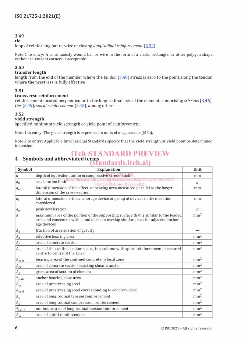
4 Symbols and abbreviated terms
Symbol Explanation Unita depth of equivalent uniform compressive stress block mma0 acceleration limit gaeff lateral dimension of the effective bearing area measured parallel to the larger
dimension of the cross-sectionmm
al lateral dimension of the anchorage device or group of devices in the direction considered
mm
ap peak acceleration gA maximum area of the portion of the supporting surface that is similar to the loaded
area and concentric with it and does not overlap similar areas for adjacent anchor-age devices
mm2
Aa fraction of acceleration of gravity —Ab effective bearing area mm2
Ac area of concrete section mm2
Acc area of the confined column core, in a column with spiral reinforcement, measured centre to centre of the spiral
mm2
Aconf bearing area of the confined concrete in local zone mm2
Acv area of concrete section resisting shear transfer mm2
Ag gross area of section of element mm2
Aplate anchor bearing plate area mm2
Aps area of prestressing steel mm2
Aps,d area of prestressing steel corresponding to concrete deck mm2
As area of longitudinal tension reinforcement mm2
As’ area of longitudinal compression reinforcement mm2
As,min minimum area of longitudinal tension reinforcement mm2
Ass area of spiral reinforcement mm2
ISO 21725-1:2021(E)
© ISO 2021 – All rights reserved
6
iTeh STANDARD PREVIEW(standards.iteh.ai)
ISO 21725-1:2021https://standards.iteh.ai/catalog/standards/sist/c8ed2099-eb6b-46c9-8cf7-
18b5570f3041/iso-21725-1-2021
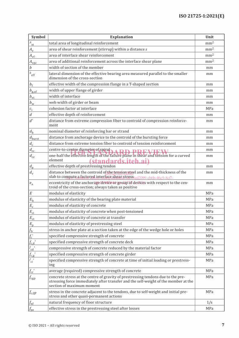
Symbol Explanation UnitA
st total area of longitudinal reinforcement mm2
Av area of shear reinforcement (stirrup) within a distance s mm2
Avf area of interface shear reinforcement mm2
Avpc area of additional reinforcement across the interface shear plane mm2
b width of section of the member mmb
eff lateral dimension of the effective bearing area measured parallel to the smaller dimension of the cross-section
mm
bf effective width of the compression flange in a T-shaped section mmbg,uf width of upper flange of girder mmbvi width of interface mmbw web width of girder or beam mmci cohesion factor at interface MPad effective depth of reinforcement mmd’ distance from extreme compression fiber to centroid of compression reinforce-
mentmm
db nominal diameter of reinforcing bar or strand mmdburst distance from anchorage device to the centroid of the bursting force mmdc distance from extreme tension fiber to centroid of tension reinforcement mmdcc centre-to-centre diameter of spiral mmdce one-half the effective length of the failure plane in shear and tension for a curved
elementmm
dp effective depth of prestressing tendon mmdv distance between the centroid of the tension steel and the mid-thickness of the
slab to compute a factored interface shear stressmm
ea eccentricity of the anchorage device or group of devices with respect to the cen-troid of the cross-section; always taken as positive
mm
E modulus of elasticity MPaEb modulus of elasticity of the bearing plate material MPaEc modulus of elasticity of concrete MPaEci modulus of elasticity of concrete when post-tensioned MPaEct modulus of elasticity of concrete at transfer MPaEp modulus of elasticity of prestressing steel MPafb stress in anchor plate at a section taken at the edge of the wedge hole or holes MPafc’ specified compressive strength of concrete MPafc,d’ specified compressive strength of concrete deck MPafcd’ compressive strength of concrete reduced by the material factor MPa
fc,g’ specified compressive strength of concrete girder MPafci’ specified compressive strength of concrete at time of initial loading or prestress-
ingMPa
fcr’ average (required) compressive strength of concrete MPafcgp concrete stress at the centre of gravity of prestressing tendons due to the pre-
stressing force immediately after transfer and the self-weight of the member at the section of maximum moment
MPa
fc,QP stress in the concrete adjacent to the tendons, due to self-weight and initial pre-stress and other quasi-permanent actions
MPa
fnf natural frequency of floor structure 1/sfpe effective stress in the prestressing steel after losses MPa
ISO 21725-1:2021(E)
© ISO 2021 – All rights reserved
7
iTeh STANDARD PREVIEW(standards.iteh.ai)
ISO 21725-1:2021https://standards.iteh.ai/catalog/standards/sist/c8ed2099-eb6b-46c9-8cf7-
18b5570f3041/iso-21725-1-2021