Embed Size (px)
Citation preview

A Reference numberISO 13702:1999(E)
INTERNATIONALSTANDARD
ISO13702
First edition1999-03-15
Petroleum and natural gas industries —Control and mitigation of fires andexplosions on offshore productioninstallations — Requirements andguidelines
Industries du pétrole et du gaz naturel — Contrôle et atténuation des feuxet des explosions dans les installations en mer — Exigences et lignesdirectrices
COPYRIGHT 2002; International Organization for Standardization
Document provided by IHS Licensee=Shell Services International B.V./5924979112,User=, 10/07/2002 03:09:54 MDT Questions or comments about this message: pleasecall the Document Policy Management Group at 1-800-451-1584.
-- | || | | |||| | | | ||| |||| || | | | |||| || | ---

ISO 13702:1999(E)
© ISO 1999
All rights reserved. Unless otherwise specified, no part of this publication may be reproduced or utilized in any form or by any means, electronicor mechanical, including photocopying and microfilm, without permission in writing from the publisher.
International Organization for StandardizationCase postale 56 • CH-1211 Genève 20 • SwitzerlandInternet [email protected]
Printed in Switzerland
ii
Contents
1 Scope ........................................................................................................................ ................................................1
2 Terms, definitions and abbreviated terms ..................................................................................... .......................1
3 Objectives................................................................................................................... ..............................................6
4 Fire and explosion evaluation and risk management ............................................................................ ..............7
5 Installation layout .......................................................................................................... ..........................................9
6 Emergency shutdown systems and blowdown...................................................................................... ............10
7 Control of ignition.......................................................................................................... ........................................11
8 Control of spills............................................................................................................ ..........................................11
9 Emergency power systems...................................................................................................... .............................11
10 Fire and gas systems ........................................................................................................ ..................................12
11 Active fire protection...................................................................................................... .....................................13
12 Passive fire protection ..................................................................................................... ...................................13
13 Explosion mitigation and protection systems................................................................................. .................14
14 Evacuation, escape and rescue............................................................................................... ...........................15
15 Inspection, testing and maintenance......................................................................................... ........................15
Annex A (informative) Typical fire and explosion hazardous events ..................................................................17
Annex B (informative) Guidelines to the control and mitigation of fires and explosions..................................21
Annex C (informative) Typical examples of design requirements for large integrated offshore installations 48
Bibliography ................................................................................................................... ...........................................55
COPYRIGHT 2002; International Organization for Standardization
Document provided by IHS Licensee=Shell Services International B.V./5924979112,User=, 10/07/2002 03:09:54 MDT Questions or comments about this message: pleasecall the Document Policy Management Group at 1-800-451-1584.
-- | || | | |||| | | | ||| |||| || | | | |||| || | ---

© ISO ISO 13702:1999(E)
iii
Foreword
ISO (the International Organization for Standardization) is a worldwide federation of national standards bodies (ISOmember bodies). The work of preparing International Standards is normally carried out through ISO technicalcommittees. Each member body interested in a subject for which a technical committee has been established hasthe right to be represented on that committee. International organizations, governmental and non-governmental, inliaison with ISO, also take part in the work. ISO collaborates closely with the International ElectrotechnicalCommission (IEC) on all matters of electrotechnical standardization.
International Standards are drafted in accordance with the rules given in the ISO/IEC Directives, Part 3.
Draft International Standards adopted by the technical committees are circulated to the member bodies for voting.Publication as an International Standard requires approval by at least 75 % of the member bodies casting a vote.
International Standard ISO 13702 was prepared by Technical Committee ISO/TC 67, Materials, equipment andoffshore structures for petroleum and natural gas industries, Subcommittee SC 6, Processing equipment andsystems.
Annexes A, B and C of this International Standard are for information only.
COPYRIGHT 2002; International Organization for Standardization
Document provided by IHS Licensee=Shell Services International B.V./5924979112,User=, 10/07/2002 03:09:54 MDT Questions or comments about this message: pleasecall the Document Policy Management Group at 1-800-451-1584.
-- | || | | |||| | | | ||| |||| || | | | |||| || | ---
ISO 13702:1999(E) © ISO
iv
Introduction
The successful development of the arrangements required to promote safety and environmental protection duringthe recovery of hydrocarbon resources, requires a structured approach to the identification and management ofhealth, safety and environmental hazards applied during the design, construction, operation, inspection,maintenance and decommissioning of a facility.
This International Standard has been prepared primarily to assist in the development of new installations and assuch it may not be appropriate to apply some of the requirements to existing installations. Retrospective applicationof this International Standard should only be undertaken where it is reasonably practicable to do so. During theplanning for a major change to an installation there may be more opportunity to implement the requirements and acareful review of this International Standard should be undertaken to determine those sections which can be utilisedin the change.
The technical content of this International Standard is arranged as follows:
Objectives - lists the goals to be achieved by the control and mitigation measures being described.
Functional requirements - represent the minimum criteria which shall be satisfied to meet the statedobjectives. The functional requirements are performance-orientated measures and, as such, should beapplicable to the variety of offshore installations utilized for the development of hydrocarbon resourcesthroughout the world.
Guidelines (annex B) - describe recognized practices which should be considered in conjunction with statutoryrequirements, industry standards and individual operator philosophy, to determine that the measures necessaryare implemented for the control and mitigation of fires and explosions. The guidelines are limited to principalelements and are intended to provide specific guidance which, due to the wide variety of offshore operatingenvironments, may in some circumstances not be applicable.
Bibliography - lists documents to which informative reference is made in this International Standard.
COPYRIGHT 2002; International Organization for Standardization
Document provided by IHS Licensee=Shell Services International B.V./5924979112,User=, 10/07/2002 03:09:54 MDT Questions or comments about this message: pleasecall the Document Policy Management Group at 1-800-451-1584.
-- | || | | |||| | | | ||| |||| || | | | |||| || | ---

INTERNATIONAL STANDARD © ISO ISO 13702:1999(E)
1
Petroleum and natural gas industries — Control and mitigation offires and explosions on offshore production installations —Requirements and guidelines
1 Scope
This International Standard describes the objectives, functional requirements and guidelines for the control andmitigation of fires and explosions on offshore installations used for the development of hydrocarbon resources.
This International Standard is applicable to:
fixed offshore structures;
floating production, storage and off-take systems;
for the petroleum and natural gas industries.
Mobile offshore units as defined in this International Standard and subsea installations are excluded, although manyof the principles contained in this International Standard may be used as guidance.
This International Standard is based on an approach where the selection of control and mitigation measures for firesand explosions is determined by an evaluation of hazards on the offshore installation. The methodologies employedin this assessment and the resultant recommendations will differ depending on the complexity of the productionprocess and facilities, type of facility (i.e. open or enclosed), manning levels, and the environmental conditionsassociated with the area of operation.
Users of this International Standard should note that while observing its requirements, they should, at the sametime, ensure compliance with such statutory requirements, rules and regulations as may be applicable to theindividual offshore installation concerned.
2 Terms, definitions and abbreviated terms
2.1 Terms and definitions
For the purposes of this International Standard, the following terms and definitions apply.
2.1.1abandonmentact of personnel onboard leaving an installation in an emergency
2.1.2accommodationplace where personnel onboard sleep and spend their off-duty time
NOTE It may include dining rooms, recreation rooms, lavatories, cabins, offices, sickbay, living quarters, galley, pantriesand similar permanently enclosed spaces.
2.1.3active fire protectionAFPequipment, systems and methods which, following initiation, may be used to control, mitigate and extinguish fires
COPYRIGHT 2002; International Organization for Standardization
Document provided by IHS Licensee=Shell Services International B.V./5924979112,User=, 10/07/2002 03:09:54 MDT Questions or comments about this message: pleasecall the Document Policy Management Group at 1-800-451-1584.
-- | || | | |||| | | | ||| |||| || | | | |||| || | ---

ISO 13702:1999(E) © ISO
2
2.1.4area classificationdivision of an installation into hazardous areas and nonhazardous areas and the sub-division of hazardous areasinto zones
NOTE This classification is based on the materials which may be present and the probability of a flammable atmospheredeveloping. Area classification is primarily used in the selection of electrical equipment to minimize the likelihood of ignition if arelease occurs.
2.1.5cellulosic fireCFfire involving combustible material such as wood, paper, furniture, etc.
2.1.6class of firetype of fireclassification used to facilitate the selection of extinguishers
2.1.7control<of hazards> limiting the extent and/or duration of a hazardous event to prevent escalation
2.1.8control stationCSplace on the installation from which personnel can monitor the status of the installation, initiate appropriateshutdown actions and undertake any emergency communication
2.1.9deluge systemsystem to apply fire-water through an array of open spray nozzles by operation of a valve on the inlet to the system
2.1.10embarkation areaplace from which personnel leave the installation during evacuation
EXAMPLES A helideck and associated waiting area or a lifeboat/liferaft boarding area.
2.1.11emergency depressurizationEDPcontrolled disposal of pressurized fluids to a flare or vent system when required to avoid or minimize a hazardoussituation
2.1.12emergency responseaction taken by personnel on or off the installation to control or mitigate a hazardous event or initiate and executeabandonment
2.1.13emergency response teamgroup of personnel who have designated duties in an emergency
2.1.14emergency shutdownESDcontrol actions undertaken to shut down equipment or processes in response to a hazardous situation
2.1.15emergency stationplace where emergency response personnel go to undertake their emergency duties
COPYRIGHT 2002; International Organization for Standardization
Document provided by IHS Licensee=Shell Services International B.V./5924979112,User=, 10/07/2002 03:09:54 MDT Questions or comments about this message: pleasecall the Document Policy Management Group at 1-800-451-1584.
-- | || | | |||| | | | ||| |||| || | | | |||| || | ---

© ISO ISO 13702:1999(E)
3
2.1.16escalationspread of impact from fires, explosions, toxic gas releases to equipment or other areas thereby causing an increasein the consequences of a hazardous event
2.1.17escapeact of personnel moving away from a hazardous event to a place where its effects are reduced or removed
2.1.18escape routeroute from an area of an installation leading to a muster area, temporary refuge (TR), embarkation area or means ofescape to the sea
2.1.19essential safety systemany system which has a major role in the control and mitigation of fires and explosions and in any subsequent EERactivities
2.1.20evacuationthe planned method of leaving the installation in an emergency
2.1.21evacuation, escape and rescueEERgeneral term used to describe the range of possible actions including escape, muster, refuge, evacuation, escape tothe sea and rescue/recovery
2.1.22evacuation, escape and rescue strategyEERSresults of the process that uses information from an evaluation of events which may require EER to determine themeasures required and the role of these measures
2.1.23evacuation routeescape route which leads from the temporary refuge (TR) to the place(s) used for primary or secondary evacuationfrom the installation
2.1.24 explosion
2.1.24.1chemical explosionviolent combustion of a flammable gas or mist which generates pressure effects due to confinement of thecombustion-induced flow and/or the acceleration of the flame front by obstacles in the flame path
2.1.24.2physical explosionexplosion arising from the sudden release of stored energy such as from failure of a pressure vessel, or highvoltage electrical discharge to earth
2.1.25fire and explosion strategyFESresults of the process that uses information from the fire and explosion evaluation to determine the measuresrequired to manage these hazardous events and the role of these measures
2.1.26flammable atmospheremixture of flammable gas or vapour in air which will burn when ignited
COPYRIGHT 2002; International Organization for Standardization
Document provided by IHS Licensee=Shell Services International B.V./5924979112,User=, 10/07/2002 03:09:54 MDT Questions or comments about this message: pleasecall the Document Policy Management Group at 1-800-451-1584.
-- | || | | |||| | | | ||| |||| || | | | |||| || | ---

ISO 13702:1999(E) © ISO
4
2.1.27functional requirementsminimum criteria which must be satisfied to meet the stated health, safety and environmental objectives
2.1.28grade of release<area classification> measure of the likely frequency and duration of a release
NOTE It is independent of the rate of release, the quantity of material released, the degree of ventilation and thecharacteristics of the fluid.
2.1.29hazardpotential for human injury, damage to the environment, damage to property, or a combination of these
2.1.30hazard assessmentprocess whereby the results of an analysis of a hazard or hazardous event are considered against eitherjudgement, standards or criteria which have been developed as a basis for decision-making
2.1.31hazardous areathree-dimensional space in which a flammable atmosphere may be expected to be present at such frequencies asto require special precautions for the control of potential ignition sources
2.1.32hazardous eventincident which occurs when a hazard is realized
EXAMPLES Release of gas, fire, loss of buoyancy.
2.1.33ignition sourcesany source with sufficient energy to initiate combustion
2.1.34integrated installationoffshore installation which contains, on the same structure, accommodation and utilities in addition to processand/or wellhead facilities
2.1.35jet fireJFignited release of pressurized, flammable fluids
2.1.36life jacketdevice worn by personnel which has sufficient buoyancy and stability to turn the body of an unconscious person andkeep the person's mouth clear of the water
2.1.37mitigation<of hazardous event> reduction of the effects of a hazardous event
2.1.38manned installationinstallation on which people are routinely accommodated
2.1.39mobile offshore unitmobile platform, including drilling ships, equipped for drilling for subsea hydrocarbon deposits, and mobile platformfor purposes other than production and storage of hydrocarbon deposits
COPYRIGHT 2002; International Organization for Standardization
Document provided by IHS Licensee=Shell Services International B.V./5924979112,User=, 10/07/2002 03:09:54 MDT Questions or comments about this message: pleasecall the Document Policy Management Group at 1-800-451-1584.
-- | || | | |||| | | | ||| |||| || | | | |||| || | ---

© ISO ISO 13702:1999(E)
5
2.1.40muster areadesignated area where personnel report when required to do so
2.1.41operatorindividual, partnership, firm or corporation having control or management of operations on the leased area or aportion thereof
NOTE The operator may be a lessee, designated agent of the lessee(s), or holder of operating rights under an approvedoperating agreement.
2.1.42passive fire protectionPFPcoating or cladding arrangement or free-standing system which, in the event of fire, will provide thermal protection torestrict the rate at which heat is transmitted to the object or area being protected
2.1.43pool firecombustion of flammable or combustible liquid spilled and retained on a surface
2.1.44prevention<of hazardous event> reduction of the likelihood of a hazardous event
2.1.45primary method<for evacuation> preferred method of leaving the installation in an emergency
2.1.46rescueprocess by which those who have entered the sea directly or in TEMPSC/liferafts are retrieved to a place wheremedical assistance is available
2.1.47riskcombination of the chance that a specified undesired event will occur and the severity of the consequences of thatevent
2.1.48running liquid firefire involving a flammable liquid flowing over a surface
2.1.49secondary method<for evacuation> method of leaving the installation which can be carried out in a fully controlled manner under thedirection of the person in charge, independent of external support
2.1.50source of releasepoint from which flammable gas, liquid or a combination of both can be released into the atmosphere
2.1.51survival suitprotective suit made of waterproof materials which reduces the body heat-loss of a person wearing it in cold water
2.1.52temporary refugeTRplace provided where personnel can take refuge for a predetermined period whilst investigations, emergencyresponse and evacuation preplanning are undertaken
COPYRIGHT 2002; International Organization for Standardization
Document provided by IHS Licensee=Shell Services International B.V./5924979112,User=, 10/07/2002 03:09:54 MDT Questions or comments about this message: pleasecall the Document Policy Management Group at 1-800-451-1584.
-- | || | | |||| | | | ||| |||| || | | | |||| || | ---

ISO 13702:1999(E) © ISO
6
2.1.53tertiary method<for escape to the sea> method of leaving the instsllation which relies considerably on the individual's own action
2.1.54totally enclosed motor-propelled survival craftTEMPSCcraft capable of sustaining the lives of persons in distress from the time of abandoning the installation
2.1.55zone<area classification> distance in any direction from the source of release to the point where the flammableatmosphere has been diluted by air to a sufficiently low level
NOTE Different zone ratings are possible depending on the frequency that flammable mixtures are expected to be present.
2.2 Abbreviated terms
AB Accommodation BlockAFP Active Fire ProtectionAPI American Petroleum InstituteBA Breathing ApparatusBOP Blowout PreventerCCR Central Control RoomCF Cellulosic FireCS Control StationEDP Emergency DepressurizationEER Evacuation, Escape and RescueEERS EER StrategyESD Emergency ShutdownFES Fire and Explosion StrategySDV Shutdown valveF&G Fire and Gas SystemHC HydrocarbonHVAC Heating, Ventilation and Air ConditioningOCS Outer Continental ShelfIEC International Electrotechnical CommissionIMO International Maritime OrganizationJF Jet FirePA Process AreaPFP Passive Fire ProtectionPLC Programmable Logic ControllersSSIV Sub-Sea Isolation ValveSSSV Sub-Surface Safety ValveTEMPSC Totally Enclosed Motor-Propelled Survival CraftTR Temporary RefugeUPS Uninterruptable Power SupplyUKOOA United Kingdom Offshore Operators AssociationUA Utility AreaWH Wellhead Area
3 Objectives
The principal objectives of this International Standard are, in order of priority:
safety of personnel;
protection of the environment;
protection of assets;
minimization of financial consequences of fires and explosions.
COPYRIGHT 2002; International Organization for Standardization
Document provided by IHS Licensee=Shell Services International B.V./5924979112,User=, 10/07/2002 03:09:54 MDT Questions or comments about this message: pleasecall the Document Policy Management Group at 1-800-451-1584.
-- | || | | |||| | | | ||| |||| || | | | |||| || | ---
© ISO ISO 13702:1999(E)
7
4 Fire and explosion evaluation and risk management
All companies associated with the offfshore recovery of hydrocarbons shall have, or conduct their activities inaccordance with, an effective management system which addresses environmental issues such as described inISO 14001 or similar1), and additionally addresses issues relating to health and safety. One key element of suchmanagement systems shall be a process of evaluation and risk management. The starting point for evaluation andrisk management is the systematic identification of the hazards and effects which may arise from offshore recoverylocations and activities and from the materials which are used or encountered in them. The identification processshould be applied to all stages in the life cycle of an installation and to all types of hazards encountered as aconsequence of the development of hydrocarbon resources.
The results of the identification process should be used both to evaluate the consequences of hazardous eventsand to determine appropriate risk reduction. The process of selecting risk-reduction measures will predominantlyentail the use of sound engineering judgement, but this may need to be supplemented by a recognition of theparticular circumstances which may require deviation from past practices and previously applied codes andstandards. In certain circumstances, risk assessment may be able to provide useful input to the decision-makingprocess, providing that the operator has established criteria for this purpose. Risk-reduction measures shouldinclude those to prevent incidents (i.e. reduction of the probability of occurrence), to control incidents (i.e. limitingthe extent and duration of a hazardous event) and to mitigate the effects (i.e. reduction of the consequences).Preventative measures, such as using inherently safer designs and ensuring asset integrity, should be emphasizedwherever practicable. Emergency response measures to recover from incidents should be provided based on theevaluation and should be developed taking into account possible failures of the control and mitigation measures.Based on the results of the evaluation, detailed health, safety and environmental objectives and functionalrequirements should be set at appropriate levels.
The above is general and applies to all hazards and potentially hazardous events. In the context of fires andexplosions, the evaluation of these events may be part of an overall installation evaluation or may be treated as aseparate process which provides information to the overall evaluation.
The results of the evaluation process and the decisions taken with respect to the need for, and role of, any riskreduction measures should be recorded so that they are available for those who operate the installation and forthose involved in any subsequent change to the installation. For convenience in the remainder of this InternationalStandard, the term 'strategy' has been adopted for this record. Two such strategies are introduced, namely a Fireand Explosion Strategy (FES) and an Evacuation, Escape and Rescue Strategy (EERS). These strategies do nothave to be separately documented and the relevant information may be included with other health, safety andenvironmental information as part of the management of all hazardous events on an installation. The EERS may, forexample be included in an overall installation Emergency Response Strategy. For many existing installations, theFES and EERS may be contained in previous risk assessments, or may be restricted to a simple statement of thestandards and/or procedures, which are applied to deal with fire and explosion and escape and evacuation aspectsof the installation.
The strategies should be updated whenever there is a change to the installation which may affect the managementof the fire and explosion hazardous events.
The level of detail in a strategy will vary depending on the scale of the installation and the stage in the installationlife cycle when the risk management process is undertaken. For example:
complex installations, e.g. a large production platform incorporating complex facilities, drilling modules andlarge accommodation modules, are likely to require detailed studies to address the fire and explosionhazardous events. Typical examples of some of the issues that may need to be addressed for suchinstallations are given in annex C;
for simpler installations, e.g. a wellhead platform or other small platforms with limited process facilities, it maybe possible to rely on application of recognized codes and standards as a suitable base which reflects industryexperience for this type of facility;
1) For example, operators should have an effective management system. Contractors should have either their ownmanagement system or conduct their activities consistently with the operators management system.
COPYRIGHT 2002; International Organization for Standardization
Document provided by IHS Licensee=Shell Services International B.V./5924979112,User=, 10/07/2002 03:09:54 MDT Questions or comments about this message: pleasecall the Document Policy Management Group at 1-800-451-1584.
-- | || | | |||| | | | ||| |||| || | | | |||| || | ---

ISO 13702:1999(E) © ISO
8
for installations which are a repeat of earlier designs, evaluations undertaken for the original design may bedeemed sufficient to determine the measures needed to manage the fire and explosion hazardous events, butnew knowledge and technology should be considered;
for installations in the early design phases, the evaluations will necessarily be less detailed than thoseundertaken during later design phases.
The strategies should describe the role and any functional requirements for each of the systems required tomanage possible hazardous events on the installation. In developing functional requirements, the following shouldbe considered:
a) the functional parameters of the particular system. This should be a statement of the purpose and essentialduties that the system is expected to perform;
b) the integrity, reliability and availability of the system;
c) the survivability of the system under the emergency conditions which may be present when it is required tooperate;
d) the dependency on other systems which may not be available in an emergency.
The identified essential elements should form the basis for the specification for each of the systems to be provided,and should be verified for the life of the installation in order to ensure that the strategies remain valid and to identifythe need for any remedial action.
In developing the strategies, there are a wide range of issues which should be considered to ensure that themeasures selected are capable of performing their function when required to do so. For the FES, these issuesinclude:
the nature of the fires and explosions which may occur (see annex A);
the risks of fires and explosions;
the marine environment;
the nature of the fluids to be handled;
the anticipated ambient conditions;
the temperature and pressure of fluids to be handled;
the quantities of flammable materials to be processed and stored;
the amount, complexity and layout of equipment on the installation;
the location of the installation with respect to external assistance/support;
the EERS;
the production and manning philosophy;
human factors.
For the EERS, issues to be considered include:
normal means of access to the installation;
means available for evacuation, escape and rescue and their likely availability in the identified accidentscenarios;
fire and explosion scenarios which might lead to the need for escape or evacuation (including the effects ofsmoke and radiant heat);
COPYRIGHT 2002; International Organization for Standardization
Document provided by IHS Licensee=Shell Services International B.V./5924979112,User=, 10/07/2002 03:09:54 MDT Questions or comments about this message: pleasecall the Document Policy Management Group at 1-800-451-1584.
-- | || | | |||| | | | ||| |||| || | | | |||| || | ---

© ISO ISO 13702:1999(E)
9
number and distribution of personnel;
emergency command and communication;
emergency monitoring and control;
layout of the installation and arrangement of equipment;
environment in which the installation is located;
level of assistance available from external sources;
any regulations and guidance which are applicable to the installation;
human factors.
The following clauses of this International Standard identify requirements and provide guidance on a range ofmeasures which may have a role in either the control and mitigation of the potential fire and explosion hazardousevents on an installation or in the EER activities which may be required as a result of a fire or explosion.
5 Installation layout
5.1 Objectives
• To minimize the possibility of hazardous accumulations of both liquids and gaseous hydrocarbon, and toprovide for the rapid removal of any accumulations which do occur;
• To minimize the probability of ignition;
• To minimize the spread of flammable liquids and gases which may result in a hazardous event;
• To separate areas required to be nonhazardous from those designated as being hazardous;
• To minimize the consequences of fire and explosions;
• To provide for adequate arrangements for escape and evacuation;
• To facilitate effective emergency response.
5.2 Functional requirements
The layout of an installation may have a major effect on the consequences of fires and explosions and on thearrangements required for EER. Consequently, for a new installation or the modification of an existing installationthe impact of layout options on the FES and EERS shall be fully evaluated as a basis for the selection of the designwhich, so far as is reasonably practicable, minimizes the risks of fire and explosion.
In developing the layout of the installation, consideration shall be given to maximizing so far as is reasonable theseparation by distance of the temporary refuge (TR), accommodation and evacuation, escape and rescue (EER)facilities from areas containing equipment handling hydrocarbons.
Either separation by distance or the use of barriers can prevent the escalation of fire to another area. Where suchbarriers are required to avoid escalation, they shall be adequate to resist fire and, as far as is reasonable the effectsof explosions. The provision of such barriers will influence ventilation, access/escape routes, ESD/EDP systemdesign, explosion resistance and firewater demands. The interdependency of safety systems shall be consideredduring the design of the installation. Any penetration of a barrier provided to prevent escalation of a fire or explosionshall not jeopardize the integrity of the barrier.
COPYRIGHT 2002; International Organization for Standardization
Document provided by IHS Licensee=Shell Services International B.V./5924979112,User=, 10/07/2002 03:09:54 MDT Questions or comments about this message: pleasecall the Document Policy Management Group at 1-800-451-1584.
-- | || | | |||| | | | ||| |||| || | | | |||| || | ---
ISO 13702:1999(E) © ISO
10
Essential safety systems (such as control stations, temporary refuge, muster areas, fire pumps) shall be locatedwhere they are least likely to be affected by fires and explosions. In some situations such systems will need to bedesigned to withstand fire and explosions, at least until people on board have been safely evacuated or the situationhas been brought under control.
The installation layout may result in equipment being at risk from impact of dropped objects or collisions. The needto protect critical items of process equipment, especially where failure could result in a major loss of inventory, shallbe considered to determine whether impact protection is required.
6 Emergency shutdown systems and blowdown
6.1 Objective
• To initiate appropriate shutdown, isolation and blowdown actions to prevent escalation of abnormal conditionsinto a major hazardous event and to limit the extent and duration of any such events which do occur.
6.2 Functional requirements
An emergency shutdown (ESD) system shall be provided, in accordance with the requirements of the FES, in orderto:
isolate the installation from the major hydrocarbon inventories within pipelines and reservoirs which, if releasedon failure, would pose an intolerable risk to personnel, environment and the equipment;
where appropriate, sectionalize topside inventory to limit the quantity of material released on loss ofcontainment;
control potential ignition sources such as fired units, engines and non-essential electrical equipment;
control subsurface safety valve(s);
where appropriate, depressurize hydrocarbon inventory and vent it to a safe place.
An ESD system shall be designed such that it is capable of fulfilling its function under the conditions which may beexperienced when the system is required to operate.
An ESD system shall provide adequate information at a control station so that personnel involved in managing anemergency have the information they need. The information presented to the operator and the controls providedshall be such that the operator can effectively execute the required actions in an emergency.
If plant is in operation, the essential shutdown functions shall be available during maintenance activities which affectthe operation of the ESD system.
Emergency depressurization (EDP) systems shall be considered for pressurized hydrocarbon systems to dispose ofthe gaseous inventory under emergency conditions in order to reduce the duration of an event, the quantity ofmaterial released or the likelihood of a pressure vessel failure in a fire.
The design of an ESD system may be for manual or automatic initiation or both. When manual initiation is required,the systems shall be simple to operate and shall not require operators to make complex or non-routine decisions.
Once initiated, all control actions required by the ESD system shall occur automatically.
Manual stations for initiation of ESD shall be located in strategic positions, be readily accessible, well marked andprotected against unintentional activation.
The ESD system shall contain facilities for testing of both input/output devices and internal functions.
COPYRIGHT 2002; International Organization for Standardization
Document provided by IHS Licensee=Shell Services International B.V./5924979112,User=, 10/07/2002 03:09:54 MDT Questions or comments about this message: pleasecall the Document Policy Management Group at 1-800-451-1584.
-- | || | | |||| | | | ||| |||| || | | | |||| || | ---

© ISO ISO 13702:1999(E)
11
7 Control of ignition
7.1 Objective
• To minimize the likelihood of ignition of flammable liquids and gases following a loss of containment.
7.2 Functional requirements
Arrangements to minimize the likelihood of ignition shall be provided in accordance with the requirements of theFES. This should include minimization of the number of potential ignition sources as far as reasonably practicable.
Ignition of flammable liquid and gas leaks shall be minimized by identifying those areas where such leaks are likelyto occur and by providing in these areas equipment which is designed to reduce the likelihood of ignition offlammable liquids and gases.
The installation shall be classified into hazardous and nonhazardous areas in accordance with a recognizedstandard or code.
The need for the ESD system to incorporate isolation of electrical equipment which is not suitable for use inhazardous areas during major gas emergencies shall be considered in the design of the ESD system.
Procedures to control the use of temporary equipment which may present ignition sources shall be established.
Direct-fired equipment shall be located or protected to prevent ignition following loss of containment.
8 Control of spills
8.1 Objective
• To provide measures for containment and proper disposal of flammable liquid spills.
8.2 Functional requirements
Arrangements for control of spills shall be provided in accordance with the requirements of the FES.
Measures shall be provided for dealing with spills in all areas which have a source of liquid hydrocarbons so as tominimize the risk of fires and to avoid damage to the environment.
Hazardous and nonhazardous open drains shall be physically separate.
Hazardous closed drains shall be separate from all open drainage systems.
The design of the drainage system shall limit the maximum spread of a spill and attempt to minimize any escalationarising from the spill.
9 Emergency power systems
9.1 Objective
• To provide a reliable source of emergency power.
9.2 Functional requirements
Emergency power shall be provided in accordance with the requirements of the FES.
Systems requiring electrical power to fulfil their functions and to allow the installation to be safely shut down andevacuated shall have a secure power supply of sufficient capacity and duration for a period sufficient for effectivemanagement of the installation while main power generation is unavailable.
COPYRIGHT 2002; International Organization for Standardization
Document provided by IHS Licensee=Shell Services International B.V./5924979112,User=, 10/07/2002 03:09:54 MDT Questions or comments about this message: pleasecall the Document Policy Management Group at 1-800-451-1584.
-- | || | | |||| | | | ||| |||| || | | | |||| || | ---

ISO 13702:1999(E) © ISO
12
Facilities shall be provided to allow maintenance of the emergency power system without significantly reducing thefunctionality of the system.
The location and design of the emergency power systems shall ensure that they will be able to perform theirfunction under the conditions which may be experienced when called upon to operate.
Consideration shall be given to the facilities required to maintain control of drilling activities. The consequences ofloss of mains power during drilling activities shall be evaluated to ensure that the emergency power systems, wherenecessary to allow essential equipment to remain available, are suitable for use during an emergency.
10 Fire and gas systems
10.1 Objectives
• To provide continuous automatic monitoring functions to alert personnel of the presence of a hazardous fire orgas condition.
• To allow control actions to be initiated manually or automatically in order to minimize the likelihood ofescalation.
10.2 Functional requirements
A Fire and Gas (F&G) system shall be provided in accordance with the requirements of the FES.
The FES shall describe the basis for determining the location, number and types of detectors. This requires aprocess of identifying and assessing the possible F&G hazardous events in each area and evaluating therequirements to reliably detect these events.
The F&G detection devices shall be selected taking into account their response characteristics and the conditionswhich may be experienced when detection is required.
Fire detectors shall be selected to be suitable for detection of the types of fires that may occur in the area.
All F&G field devices shall be suitable for the area in which they will be located and shall be approved for use by arecognized authority.
When necessary to prevent ignition of a gas release in nonhazardous areas, the air intakes to these areas, or theareas themselves, shall be fitted with gas detection if gas can realistically reach these areas in an emergency.Reliance on gas detection within a nonhazardous area to prevent ignition of gas needs careful consideration toensure that sufficient time will be available after initial detection to complete the necessary shutdown actions.
The F&G system shall have facilities to allow testing of field devices, the system internal functions and executiveoutputs.
Devices to initiate F&G alarm and, where provided, control actions shall be available in a control station.
Alarm conditions requiring muster of personnel shall be identified by acoustic signals, supplemented by visualsignals in high noise areas where high noise levels will persist after ESD.
Temporary removal or isolation of the F&G system, or part of the system, is acceptable providing that adequatealternative arrangements are provided.
The F&G information required at the TR and control stations shall be considered during the design of the system.The F&G control system shall be designed, located or protected so that it will be available in those emergencieswhere fire and gas detection is required.
COPYRIGHT 2002; International Organization for Standardization
Document provided by IHS Licensee=Shell Services International B.V./5924979112,User=, 10/07/2002 03:09:54 MDT Questions or comments about this message: pleasecall the Document Policy Management Group at 1-800-451-1584.
-- | || | | |||| | | | ||| |||| || | | | |||| || | ---

© ISO ISO 13702:1999(E)
13
11 Active fire protection
11.1 Objectives
• To control fires and limit escalation;
• To reduce the effects of a fire to allow personnel to undertake emergency response activities or to evacuate;
• To extinguish the fire where it is considered safe to do so;
• To limit damage to structures and equipment.
11.2 Functional requirements
Active Fire Protection (AFP) systems shall be provided in accordance with the requirements of the FES.
AFP systems shall be designed, installed and maintained in accordance with recognized standards which shall berelevant to the particular application.
If considered essential, AFP systems shall be located or protected so that they will be able to withstand theexpected fire or explosion loading.
The discharge effects from an AFP system shall be considered in selection of the system for particular areas (forexample, the effects of water on electrical equipment).
The capacity and discharge density (or application rate) of AFP systems and equipment shall be determined eitherby engineering evaluation or through use of a relevant recognized standard.
AFP systems and equipment shall be suitable for the intended duty and environment. Major components shall be ofa type approved by a recognized testing authority. The conditions of approval shall be relevant to the intendedoperating environment.
All AFP systems and equipment shall be marked with easily understood operating instructions.
The response time for activation and reaching an operational state for all AFP systems shall not affect the ability ofthe system to fulfil its intended function.
For automatically initiated systems, a manual release station shall be provided and conveniently located outside theprotected area.
The information required at the control station shall be considered in the design of the AFP system.
AFP systems shall be returned to service following use. Where systems cannot be immediately returned to servicealternative actions to minimize the fire risks shall be considered and implemented where appropriate, beforeresumption of operations in the affected area.
NOTE The most effective way to limit escalation and damage is to detect and control fires at an early stage. In practice, firecontrol cannot be achieved until the source of fuel and ignition is isolated.
For some fire events, it may not be practical or necessary to provide AFP systems to extinguish the fire. In addition,extinguishment may create a greater hazard due to an increased potential for an explosion should gas from arelease subsequently re-ignite.
12 Passive fire protection
12.1 Objectives
• To prevent escalation of the fire due to progressive releases of inventory, by separating the different fire riskareas;
COPYRIGHT 2002; International Organization for Standardization
Document provided by IHS Licensee=Shell Services International B.V./5924979112,User=, 10/07/2002 03:09:54 MDT Questions or comments about this message: pleasecall the Document Policy Management Group at 1-800-451-1584.
-- | || | | |||| | | | ||| |||| || | | | |||| || | ---

ISO 13702:1999(E) © ISO
14
• To protect essential safety systems;
• To protect critical components, such as separators, risers and topside ESD valves;
• To minimize damage to the installation by protecting the critical structural members, and in particular thosemembers essential to the support of the TR(s), the evacuation routes to and from the TR(s) and other criticalequipment;
• To encourage controlled collapse of tall structures to minimize the likelihood of collapse of structures andequipment onto TR/evacuation facilities;
• To protect personnel in the TR(s), until safe evacuation can take place;
• To protect any section of the escape routes to the TR(s) for a predetermined time to allow for safe escape fromthe area and allow for emergency response activities;
• To protect any sections of the evacuation routes from the TR(s) to the locations used for installationevacuation.
12.2 Functional requirements
Passive Fire Protection (PFP) shall be provided in accordance with the requirements of the FES.
PFP of essential systems and equipment or enclosures containing such systems and equipment shall be providedwhere failure in a fire is intolerable.
Where PFP is required to provide protection following an explosion, it shall be designed and installed such thatdeformation of the substrate caused by an explosion will not affect its performance.
Selection of the PFP systems shall take into account the duration of protection required, type of fire which may beexperienced and the limiting temperature for the structure/equipment to be protected.
13 Explosion mitigation and protection systems
13.1 Objective
• To reduce to an acceptable level the probability of an explosion leading to unacceptable consequences.
13.2 Functional requirements
Measures to prevent, control and mitigate explosions shall be provided in accordance with the requirements of theFES. These measures should fulfil at least one of the following requirements:
• Reduce the probability of an explosion occurring.
• Control an explosion by mitigation techniques that reduce explosion loads to acceptable levels.
• Mitigate the consequences of an explosion and reduce the likelihood of escalation as a result of explosionloads.
As input to the FES, an evaluation of explosion loads and the associated probabilities of exceeding those loadsshall be performed. Similarly, it is recommended to evaluate the probabilities of critical structures and equipmentresponding in an unacceptable manner to these explosion loads (e.g. by leading to escalation).
In particular, the evaluation used to develop the FES shall consider all areas where the potential for a gas orvapour-cloud explosion exists. The evaluation shall identify those systems required to maintain the integrity of thestructure and the major equipment or piping systems. In particular, the possible benefits of using water deluge forexplosion control shall be evaluated. The evaluation shall also identify the potential for escalation resulting fromdamage caused by blast overpressures which would impair the operation of the essential safety systems, and theeffect of any fire which may occur after an explosion.
COPYRIGHT 2002; International Organization for Standardization
Document provided by IHS Licensee=Shell Services International B.V./5924979112,User=, 10/07/2002 03:09:54 MDT Questions or comments about this message: pleasecall the Document Policy Management Group at 1-800-451-1584.
-- | || | | |||| | | | ||| |||| || | | | |||| || | ---

© ISO ISO 13702:1999(E)
15
Functional requirements for passive explosion protection systems, when required by the FES, shall be expressedas pressure/loadings time histories, which are generated either from experimental/test data or from suitablecomputer models. The response calculations shall be accounted for in the dynamic analysis or other acceptableanalysis methodology.
Where explosion mitigation measures are provided, they shall be designed to limit blast overpressures and/or tohave adequate strength.
14 Evacuation, escape and rescue
14.1 Objectives
• To maintain the safety of all personnel when they move to another location to avoid the effects of a hazardousevent;
• To provide a refuge on the installation for as long as required for a controlled evacuation of the installation;
• To facilitate rescue of injured personnel;
• To ensure safe abandonment of the installation.
14.2 Functional requirements
EER arrangements shall be provided in accordance with the requirements of the EERS.
The EERS shall be based on an EER assessment which considers the wide range of events which may arise andcontain a viable approach for all these events.
The EERS shall also address issues such as organization, procedures, information, training and emergencyresponse which are necessary to achieve a successful EER process.
Escape routes shall be provided to enable all personnel to leave an area when they are directly affected by anincident.
A command structure shall be established that will, so far as is reasonably practicable, remain effective throughoutall stages of an emergency.
A place shall be provided where personnel can muster while investigations, emergency response and evacuationpre-planning are undertaken.
Communication systems shall be provided to allow personnel on the installation to effectively execute theiremergency duties.
Arrangements shall be provided on the installation so that personnel can evacuate in an emergency and, ifnecessary, escape to the sea.
Arrangements for rescue and recovery of personnel who abandon the installation shall be selected to provide agood prospect of being able to safely transfer them to a place of safety.
15 Inspection, testing and maintenance
15.1 Objective
• To inspect, test and maintain systems and equipment covered by this International Standard to ensure thatthey are fit for purpose.
COPYRIGHT 2002; International Organization for Standardization
Document provided by IHS Licensee=Shell Services International B.V./5924979112,User=, 10/07/2002 03:09:54 MDT Questions or comments about this message: pleasecall the Document Policy Management Group at 1-800-451-1584.
-- | || | | |||| | | | ||| |||| || | | | |||| || | ---
ISO 13702:1999(E) © ISO
16
15.2 Functional requirements
As part of an overall HS&E management system, each operator shall establish effective operations, inspection,testing and maintenance procedures to ensure the functional requirements of the equipment and systems providedare maintained. This shall be achieved by implementation of suitable maintenance, inspection and testing schemes,taking due account of the safety of personnel, protection of the environment and compliance with any localregulatory requirements.
In order to provide effective procedures, it will be necessary for the following to be carried out.
a) Systems shall be subjected to appropriate testing prior to first use to confirm that they will meet the appropriatefunctional requirements.
b) A written scheme shall be prepared, detailing the inspection, testing and maintenance routines and frequenciesto be followed.
c) All systems shall be thoroughly inspected, following established procedures. This will determine if remedialmeasures are needed so that the item inspected will function satisfactorily.
d) Adequate records of the results of the inspection, testing and maintenance shall be kept and shall beperiodically reviewed to confirm that the written scheme is appropriate and is being adequately implemented.
e) The maintenance procedures shall include for regular visual inspection.
f) Appropriate operational tests shall be conducted.
g) The latest inspection/test report shall be available on the installation.
h) Use, impairment and restoration of equipment or systems shall be recorded and reported as appropriate.
i) Any identified failures or impairments shall be promptly corrected. Where equipment cannot be promptlyreturned to service, contingency plans shall be implemented.
COPYRIGHT 2002; International Organization for Standardization
Document provided by IHS Licensee=Shell Services International B.V./5924979112,User=, 10/07/2002 03:09:54 MDT Questions or comments about this message: pleasecall the Document Policy Management Group at 1-800-451-1584.
-- | || | | |||| | | | ||| |||| || | | | |||| || | ---

© ISO ISO 13702:1999(E)
17
Annex A(informative)
Typical fire and explosion hazardous events
A.1 General
Whilst good techniques exist to calculate the loadings and responses to some of the hazardous events which mayoccur, others are still the subject of research. Users of this International Standard who need this information shouldconsult references such as those issued by the SCI (Steel Construction Institute), SINTEF (Foundation for Scientificand Industrial Research, Norway), CMR (Christian Michelsen Research) and TNO (Netherlands Organization forApplied Scientific Research) for further details. Some of the key features of fires and explosions are given below.
A.2 Fire events
A pool fire is the turbulent diffusion fire burning above a horizontal pool of vaporizing hydrocarbon fuel underconditions where the fuel has zero or very low initial momentum. There is a degree of feedback between the fire andthe fuel which controls the rate of evaporation and hence the size of the fire and other characteristics such as flameheight and smoke production rates. A pool fire is not necessarily static and may spread or contract depending onthe supply of fuel. Depletion of fuel can occur due to drainage or overflow to other areas, perhaps giving rise torunning liquid fires. The fire has inertia in that it takes time to develop and cannot be eliminated quickly by isolatingthe fuel supply.
Running liquid fires are broadly similar to pool fires in that they rely on thermal feedback from the flame for their fuelvapour supply, but the liquid fuel is in motion and can be on surfaces of any orientation.
A jet fire in the open is a turbulent diffusion flame resulting from the combustion of a fuel continuously released withsome significant momentum in a particular direction. In jet fires there is the absence of any direct feedback from thefire to the source. For fires in the open, this suggests that jet fire hazards can be treated more deterministically thanpool fires, as the mass flowrate and the behaviour with time is determined to a large degree by the leakcharacteristics. Unlike pool fires, jet fires have minimal inertia and reach their full intensity almost instantaneously. Inprinciple they can be turned off very quickly and thus isolation and minimization of inventory are importanttechniques to reduce the potential impact of jet fires.
A cellulosic fire is a fire involving materials such as rags, paper and wood. In addition, many surface linings used onwalls, floors and ceilings give the same type of fire. The fire grows by heat transfer and flame spread. When the firehas developed, all three modes of heat transfer (convection, conduction and radiation) contribute to fire growth untilthere is no more flammable material. Compared to hydrocarbon fires, the development of cellulosic fires is slowerand they do not usually reach such high temperatures.
The behaviour of all fires is changed by reduction in the ventilation from that available in the open. In the absence ofall ventilation fires cannot continue to burn, but there are likely to be relatively few situations on offshore installationswhere this is possible. At intermediate levels of ventilation, knowledge of the effect on fire characteristics is limitedbut it appears that the extent of flaming, and hence the amount of equipment engulfed in the fire, can be significantlyhigher than for fires in the open. The concentration of carbon monoxide in smoke increases as the ventilation isrestricted. Assessment of fire hazards should ensure that methods of prediction of fire size and heat transfer ratesare validated and are relevant to the particular application.
A.3 Explosion events
An explosion is a sudden and violent release of energy, with a typical duration of the order of 1 s to 2 s. Anymeasures intended to control or mitigate an explosion must take this behaviour into account.
COPYRIGHT 2002; International Organization for Standardization
Document provided by IHS Licensee=Shell Services International B.V./5924979112,User=, 10/07/2002 03:09:54 MDT Questions or comments about this message: pleasecall the Document Policy Management Group at 1-800-451-1584.
-- | || | | |||| | | | ||| |||| || | | | |||| || | ---

ISO 13702:1999(E) © ISO
18
The violence of an explosion depends on the rate at which energy is released. In offshore design, two types ofenergy are considered, namely physical energy and chemical energy.
Physical energy may be represented as pressure energy in gases, strain energy in metals and electrical energy. Atypical example on offshore installations may be failure of a fitting on high-pressure gas systems. Physical energywhen released may cause blast effects but will primarily create projectiles, which may cause escalation if thesecause damage to hydrocarbon-containing equipment.
Chemical energy is released following a chemical reaction, an example of which is the combustion of a premixedfuel/air cloud, creating the pressure build-up that might characterize an explosion. Chemical energy will createoverpressure/impulse, drag forces and eventually projectiles from objects due to the overpressure and/or the dragforces. All these effects have to be considered in developing the FES.
Explosion overpressure will generally increase with increased confinement and/or congestion of the affected area.
The overpressure, drag forces and projectiles are capable of causing injury to personnel as well as causingstructural failure and damage to plant and equipment unless appropriate action is taken.
A.4 Potential ignition sources
A.4.1 General
Ignition occurs when sufficient heat is present to cause combustion. Factors influencing resultant combustion from agiven ignition source are temperature, exposure time and energy. Ignition sources that may be present in offshoreinstallations are discussed in A.3.2 to A.3.9.
A.4.2 Chemical reactions
Chemical reactions may produce heat. This heat can ignite the substances reacting, products of the chemicalreaction or nearby materials. An example of a chemical reaction that might occur on an offshore installation is auto-ignition of oil-soaked lagging on hot pipework.
Offshore facilities where hydrogen sulfide is present may develop pyrophoric iron sulfide as a product of corrosionof steel in the absence of oxygen. This is a highly reduced form of iron sulfide, which will convert to a more stableform on exposure to air with the release of heat which may cause the material to glow and ignite any hydrocarbon(HC) which may be present.
A.4.3 Electric sparks and arcs
An electric spark is a discharge of electric current across a gap between two charged objects. Although staticelectricity and lightning are forms of electric sparks, they are listed as separate ignition sources to emphasize theirimportance. Electric sparks from many of the electrical supplies on an offshore installation may contain sufficientenergy to ignite a flammable mixture. An electric arc occurs when an electric circuit carrying current is interrupted,either intentionally as by a switch or accidentally as when a contact or terminal becomes loosened or a current-carrying conductor is broken. Sources of electric sparks and arcs can be the following:
electric motors and generators;
switches, relays and other arcing components of electric circuits under normal operating conditions;
electric wiring and equipment malfunctions;
electric arc welding;
storage batteries;
fired equipment ignition devices;
internal combustion engine electrical systems;
COPYRIGHT 2002; International Organization for Standardization
Document provided by IHS Licensee=Shell Services International B.V./5924979112,User=, 10/07/2002 03:09:54 MDT Questions or comments about this message: pleasecall the Document Policy Management Group at 1-800-451-1584.
-- | || | | |||| | | | ||| |||| || | | | |||| || | ---

© ISO ISO 13702:1999(E)
19
lighting fixtures;
radio-frequency energy;
impressed current cathodic protection systems.
A.4.4 Mechanical sparks
A mechanical spark is energy generated by mechanical friction created by metal tools and falling objects. Thisenergy is likely to be high enough to ignite a flammable mixture.
A.4.5 Lightning
Lightning is the discharge of an electric charge on a cloud to an opposite charge on another cloud or on the earth.Lightning can develop very high temperatures in any material of high resistance in its path. Lightning tends todischarge to high points such as antennae and flare/vent stacks. The design of offshore installations usuallyensures that lightning is not a major source of hazard except to some well operations involving explosives and atany unignited vent.
A.4.6 Static electrical sparks
If two objects are in close physical contact and then separated, the objects sometimes collect an electric chargethrough friction or induction. Similarly, electric charges can be generated by rapid flow of gases or liquids.
If the objects are not earthed, grounded or bonded, they may accumulate sufficient electric charges that a sparkdischarge may occur. These static electrical sparks are normally of very short duration and do not produce sufficientheat to ignite ordinary combustible materials, such as paper. Some, however, are capable of igniting flammablevapours and gases. This situation is more common in a dry atmosphere. Static electrical sparks may be a problemin situations such as the following:
fuelling operations;
filling containers, tanks and pressure vessels;
high fluid exit velocities (high-pressure water sprays, gas jets);
drive belt operation;
shot blasting;
steam cleaning;
snowstorm.
A.4.7 Flame
When fuels are burned, energy is released in the form of heat. The burning is generally accompanied by aluminosity called flame. Examples of situations where flames may be present on an offshore installation are thefollowing:
hydrocarbon flaring;
fired equipment (boilers, heaters);
gas welding and cutting;
engine operation (backfire and exhaust gases);
personnel smoking;
operation of heating and cooking appliances.
COPYRIGHT 2002; International Organization for Standardization
Document provided by IHS Licensee=Shell Services International B.V./5924979112,User=, 10/07/2002 03:09:54 MDT Questions or comments about this message: pleasecall the Document Policy Management Group at 1-800-451-1584.
-- | || | | |||| | | | ||| |||| || | | | |||| || | ---

ISO 13702:1999(E) © ISO
20
A.4.8 Hot surfaces
Hot surfaces can be a source of ignition. These sources may include the following:
welding slag and hot metal particles (sparks);
fired vessel stacks;
hot processing piping and equipment;
engine exhaust systems;
high-temperature electrical devices, such as incandescent lighting fixtures or heating elements;
frictional heat such as slipping belt against a pulley, un-lubricated bearings;
heating and cooking appliances;
clothes dryers and exhaust systems.
A.4.9 Heat of compression
If a flammable mixture is compressed rapidly, it will ignite when the heat generated by the compressing action issufficient to raise the temperature of the mixture to its ignition point. Combustion as a result of heat of compressionmay occur when hydrocarbon vapours or gases are mixed with air under situations such as the following:
improper purging of pressure vessels and other equipment when introducing hydrocarbons;
packing or seal failure that allows supply air to mix with supply or process hydrocarbons;
lubricating system failure in air compressors;
admission of air into the suction of hydrocarbon gas compressors.
COPYRIGHT 2002; International Organization for Standardization
Document provided by IHS Licensee=Shell Services International B.V./5924979112,User=, 10/07/2002 03:09:54 MDT Questions or comments about this message: pleasecall the Document Policy Management Group at 1-800-451-1584.
-- | || | | |||| | | | ||| |||| || | | | |||| || | ---
© ISO ISO 13702:1999(E)
21
Annex B(informative)
Guidelines to the control and mitigation of fires and explosions
B.1 Installation layout
The installation should be oriented so that, if there is a dominant wind direction, it will minimize the likelihood of agas release or smoke drifting towards the accommodation and primary evacuation points. If ingress of smoke or gasinto the accommodation is possible, the design of any ventilation system should be such as to minimize thelikelihood of contamination of the inside of the accommodation and spaces occupied during emergencies.Oninstallations where the accommodation is on the same structure as the processing facilities, consideration should begiven to the appropriate siting of the accommodation to minimize the likelihood of impairment by fires andexplosions. In some cases, locating the accommodation on a lower level of the installation may be appropriate.
The amount of venting available and the degree of congestion in the area of the explosion significantly influence theseverity of an explosion.
Examples which illustrate the effect of module geometry on explosions are provided in B.10 and B.11.
In this respect, the following points should be considered.
a) Long and narrow modules containing pressurized hydrocarbon systems should be avoided, as large distancebetween possible ignition points and the vent can contribute to high over pressures. If long, narrow modulescannot be avoided, vents or open areas should be located in the longer walls;
b) Explosion pressure is dependent on blockage, so blockage should be reduced;
c) Repeated obstacles should be avoided. If this cannot be achieved, vent openings along the wall with therepeated obstacles should be provided.
Where explosion vents are provided, the vents should be located to minimize the distance between any potentialsource of ignition and the vent. The vents themselves should have the maximum possible free area. Thearrangement of equipment in an area, and particularly near the vent, can have a major influence on the peakoverpressures expected in an area.
Main evacuation routes, essential safety systems and vulnerable process equipment should not be located in thepath of explosion vents, due to possible damage by blast effects and flying debris. Furthermore, such equipmentshould not be placed close to barriers which may be displaced in an explosion.
Cable trays, junction boxes, piping and miscellaneous equipment should not be allowed to block the explosion ventsand reduce the free vent area, nor should they be located where they will increase turbulence and thus explosionoverpressures.
Services for essential safety systems should be routed to ensure they will be able to perform their function in anemergency. If it is not possible to eliminate exposure to fires and explosions or to adequately protect them, routingby diverse paths may ensure adequate integrity for essential safety systems. Care should be taken to ensure thatloss of part of a system will not jeopardize the whole system.
Risers and conductors should be designed and positioned or protected to minimize the likelihood of damage,including that due to ship impact and dropped objects.
Topsides riser ESD valves should be located as low down the riser as practicable, so as to minimize the likelihoodof damage below the ESD and release of non-isolatable pipeline inventories. Alternatively, riser ESD valves may beprotected to withstand the effects of such accidental loadings. Riser ESD valves should be located to allow accessfor operation, maintenance and inspection.
COPYRIGHT 2002; International Organization for Standardization
Document provided by IHS Licensee=Shell Services International B.V./5924979112,User=, 10/07/2002 03:09:54 MDT Questions or comments about this message: pleasecall the Document Policy Management Group at 1-800-451-1584.
-- | || | | |||| | | | ||| |||| || | | | |||| || | ---
ISO 13702:1999(E) © ISO
22
The installation design should consider how an ignited blowout can be handled should such an event occur on theinstallation. The design should consider the strategy for well killing and the role of any multipurpose support vesselwhich may be available. The ability of the blowout preventer (BOP) and diverter assemblies to perform theirfunctions under major emergency conditions should also be addressed.
Effective ventilation of hazardous areas will aid dispersion of small releases, reduce the likelihood of flammableatmospheres accumulating and minimize the duration of any accumulations which do occur.
Ventilation systems supplying air to hazardous areas should take air from nonhazardous areas.
Ventilation discharges from hazardous areas should be located so that any emissions will not present a hazard topersonnel during normal operations and under emergency conditions.
Where utilities, such as cooling water, are shared by process systems and equipment in nonhazardous areas, theutility system should be designed to prevent migration of flammable liquids and gases into nonhazardous areas.
B.2 Emergency shutdown and blowdown systems
ESD systems may be based on one or more of a range of technologies including PLC (Programmable LogicControllers), electronic, electrical, pneumatic and hydraulic systems. Whatever configuration is selected, thefunctionality and performance should ensure that the system is capable of fulfilling its role as stated in the FES.
ESD systems should be designed in accordance with recognized codes or standards applicable to the area ofoperation. Methods of determining functional requirements for electrical, electronic and programmable electronicsystems and guidance on how these functional requirements can be achieved are given in Parts 1, 2 and 3 of IEC61508. Loss of power or key input signals should be considered in determining the reliability of the ESD system.
The impact of loss of power and by input signals on the functionality of the ESD system should be considered. Inmany applications this may require that the ESD system is inherently "fail safe", such that the system achieves asafe condition. For more information on hydraulic and pneumatic systems which may supply power for ESD systemoperation, see clause B.13.
Simplicity of operation and maintenance should be considered in system design.
The requirements for ESD actions with regard to drilling and well-servicing activities need special consideration.Manual initiation of ESD actions, which affect drilling or well-service operations, is usual.
Platform-based wells capable of flowing to surface should be separated from the platform by automatic downholesafety devices. ESD valves on incoming pipeline risers and well heads should be provided. The requirements forboundary isolations should also address the needs of any gas-lift lines. Riser ESD valves may need to besupplemented by subsea isolation valves to limit the duration of leaks associated with failure of a riser. The potentialbenefit of such valves including those on export pipelines, should be considered in developing the FES.
ESD valves within the topsides process systems may be required to limit the amount of hydrocarbons released onloss of containment, to separate systems with differing operating conditions, and to facilitate EDP system design.
Fast effective EDP may reduce the duration of jet fires to the extent that the need for, or the amount of active andpassive fire protection (AFP/PFP) can be reduced or omitted for some events. Reduction in system pressure byEDP will also reduce the leakage rates. However, failure of an EDP system pipework, for example in an explosion,may result in the release of part of the installation's pressurized inventory into the area.
EDP may be initiated either manually or automatically, but automatic systems are generally preferred where a delayin initiating EDP presents a significant risk to personnel or the installation. A sequenced EDP may be required onsome installations to limit the peak flowrates in the vent or flare system. Where sequenced EDP is used, the failuremodes of the timer systems should be considered to ensure that the overall system integrity is adequate. Forautomatic EDP systems, it may be acceptable to provide a cancel facility to stop or delay the EDP if the operatordecides that EDP is unnecessary or unsafe (e.g. due to helicopter operations).
COPYRIGHT 2002; International Organization for Standardization
Document provided by IHS Licensee=Shell Services International B.V./5924979112,User=, 10/07/2002 03:09:54 MDT Questions or comments about this message: pleasecall the Document Policy Management Group at 1-800-451-1584.
-- | || | | |||| | | | ||| |||| || | | | |||| || | ---

© ISO ISO 13702:1999(E)
23
The consequences of venting or flaring gas when EDP is initiated should be evaluated to confirm that this does notintroduce any unacceptable hazard due to, for example, liquid carryover, high levels of heat radiation or flammable/toxic gas affecting personnel on the installation.
The provision of an EDP system may not in itself be sufficient to prevent vessel failure if a vessel is engulfed in afire. Protection provided by EDP systems will normally only be effective if the EDP is initiated at the earliestopportunity, which is likely to require automatic initiation by the fire and gas detection (F&G) system. Where anassessment indicates that such pressure vessel failures present a significant risk, additional forms of protectionsuch as AFP/PFP should also be considered.
ESD and EDP valves should be accessible and equipped with position indicators locally and where appropriate.Valve-position indication should also be available at the control station.
The maintenance and testing requirements should be addressed during the design, and the necessary facilities toallow these activities without significantly reducing the level of safety should be provided. If maintenance and testingare not possible without significantly reducing the functionality of the system, special precautions and proceduresshould be developed to maintain an equivalent level of safety. In some cases this may require that maintenance andtesting operations are only performed when the installation is shut down.
B.3 Control of ignition
Potential ignition sources are described in annex A.
Ventilation rates in open installation will vary considerably with weather conditions and layout. Consideration of amixture of free and forced ventilation may be necessary.
In undertaking a hazardous area classification of the installation, the main factors affecting the zoning and theextent of the zones are the source and grade of release, the characteristics of the fluid released and the ventilationin the area of the release. Hazardous-area classification is intended to be applied when there may be a risk ofignition due to the presence of flammable gas and vapour mixed with air under normal conditions. It does notaddress major releases. The extent of each hazardous area or zone shall be determined using a recognizedstandard, such as IEC 79-10, Part 15 of the Institute of Petroleum Model Code of Safe Practice or API RP 500.
The rate of ventilation will influence the zoning. The effect of loss of forced ventilation or the frequency of periods oflow natural ventilation should also be considered and, if appropriate, the precautions identified to deal with theconsequent change in zone rating. Pressure differentials created by ventilation systems are also important inlimiting gas spread.
Ventilation rates for enclosed hazardous areas should take into account the amount of gaseous hydrocarbonswhich may be expected in normal operations, although some area classification codes contain minimum air changeor velocity requirements which may also be used. Air intakes for nonhazardous areas should be positioned as far asreasonably practical from hazardous areas.
All electrical equipment shall be suitable for use in the area in which it is installed.
Consideration should be given to minimizing the amount of electrical equipment installed in hazardous areas.
Electrical equipment outside the TR and control station which is required to operate during a gas emergency shouldbe suitable for operation in a flammable gas atmosphere. If essential electrical equipment remains energized in anemergency, facilities should be provided to isolate it manually or automatically. Consideration should be given totripping, either automatically or manually, all nonessential safety equipment once gas is detected in nonhazardousareas.
Nonelectrical equipment and hot surfaces may also be potential ignition sources. Precautions, such as automaticshutdown, should be provided to prevent ignition if a gas release should occur while the equipment is in use.
Diesel engines may provide a source of ignition for flammable vapours and also create a hazard by overspeedingthrough ingestion of flammable vapours. Diesel engines located in hazardous areas should be designed andinstalled in accordance with a recognized standard, such as EEMUA 170.
COPYRIGHT 2002; International Organization for Standardization
Document provided by IHS Licensee=Shell Services International B.V./5924979112,User=, 10/07/2002 03:09:54 MDT Questions or comments about this message: pleasecall the Document Policy Management Group at 1-800-451-1584.
-- | || | | |||| | | | ||| |||| || | | | |||| || | ---
ISO 13702:1999(E) © ISO
24
Diesel engines in nonhazardous areas powering essential safety systems should be provided with protection suchthat the diesel engine can continue to operate if gas can realistically reach the area in an emergency. This mayinclude isolation of non-suitable electrical components, over-speed protection and, possibly, cooling of hot surfaces.
Gas turbine acoustic hoods contain potential ignition sources and hydrocarbon sources of release in closeproximity. Provisions shall be made to supply ventilation air from a nonhazardous area at sufficient flowrates toremove heat from the surface of the equipment, to dilute any small leaks of flammable gas, and to purge theenclosure prior to start-up. Alternatively, inerting systems may be considered as a means to prevent ignition under aturbine acoustic hood if the ventilation system may shut down on gas detection. If inerting systems are used, it isvital to ensure that the turbine hood remains effectively sealed until any ignition source inside the hood areeffectively disabled.
The integrity of physical barriers between hazardous and nonhazardous areas is important to prevent gas migrationto nonhazardous areas. Penetrations between such areas should be kept to a minimum and any penetrations forpiping, cables, ducts, etc. should be adequately sealed. For heating, ventilation and air conditioning (HVAC)penetrations, dampers where provided, or ductwork should be of the same fire integrity as the boundary throughwhich any ductwork passes.
Portable or temporary equipment for use in hazardous areas shall be suitable for use in such areas. Where this isnot possible, additional precautions should be introduced to minimize the likelihood that this equipment will ignite arelease of hydrocarbons.
B.4 Control of spills
The capacity of the drainage system should be sufficient to handle credible spill coincident with deluge and/or fire-fighting activities. The design of drainage systems should make allowance for possible blockage which may restrictthe capacity of the system. When a drainage system is provided, it should be designed to prevent burning fuelspreading fire to other areas.
Separate larger drainage systems may be necessary to control major releases and any associated firewater. Inorder to limit the size of drainage recovery systems it may be acceptable to provide firewater drains which dischargefire-water directly to the sea.
Consideration should be given to the role of the drainage system to prevent a major hydrocarbon spill accumulatingunder vessels or contaminating lower levels of the installation.
Consideration should be given to the need to prevent fires spreading to sea level where they may affect the integrityof the installation-supporting structure and impede evacuation.
Helidecks should be designed to quickly remove spills of aviation fuel from the vicinity of the aircraft withoutimpeding the escape routes.
On some installations, hazardous and nonhazardous open drains may terminate in a common caisson or sump.This is acceptable providing that backflow into the nonhazardous open drains is prevented, for example by routingthe drainpipe below sea/liquid level. Where such an arrangement is used, care is needed to ensure backflow doesnot occur due to corrosion of nonhazardous drains pipework.
Kerbs or drip-pans should be provided around vessels, pumps and other potential sources of leakage to limit thespread of small spills.
Storage arrangements for movable containers of flammable liquids or gases should take account of the possibility ofleaks or spills and measures for handling these should be in place.
B.5 Emergency power systems
Emergency electrical power may be provided by one of the following systems:
an emergency generator;
COPYRIGHT 2002; International Organization for Standardization
Document provided by IHS Licensee=Shell Services International B.V./5924979112,User=, 10/07/2002 03:09:54 MDT Questions or comments about this message: pleasecall the Document Policy Management Group at 1-800-451-1584.
-- | || | | |||| | | | ||| |||| || | | | |||| || | ---

© ISO ISO 13702:1999(E)
25
installation mains power generation providing it can reliably provide power under emergency conditions;
cables with suitable integrity from land or other installations;
battery systems;
or some combinations of these.
On small simple installations it may be possible to rely entirely on battery systems.
More details of typical emergency electrical power requirements are given in clause C.1.
Consideration should be given in the design of the emergency power system to ensure that there will be adequatearrangements to provide a reliable source of power during maintenance of the emergency power system. Thedesign of the emergency electrical power system should consider providing automatic-start arrangements to avoidthe need for manual intervention during emergency condition.
Emergency lighting should be provided on routes which may be used for escape and evacuation and for thoseplaces where personnel will muster. Where emergency lighting is predominantly supplied from an emergencygenerator, a portion of the light fittings should also have battery backup.
In order to manage evacuation of the installation radio communications are required. Emergency communicationsequipment with independent battery supplies should be provided.
The duration of the uninterruptable power supply (UPS) to systems such as the emergency lighting, F&G system,emergency communications, ESD systems etc. should be designed to cater for the emergency conditions whichmay be experienced. Where UPS systems are selected they should provide power for a period considerably longerthan the TR endurance time to cater for those events where immediate evacuation is unnecessary or not practical.
The navigational aids should be provided with independent battery supplies.
Cabling for systems supplied with emergency power should be of a standard that will allow the system to operatelong enough to perform its role under the conditions which may be experienced when the emergency power isrequired and should be routed to minimize damage.
Deluge-control valves and other critical valves may be held in the closed position by the instrument air system. In amajor gas emergency, mains power generation may stop, resulting in the loss of the instrument air compressor(s). Ifthe integrity of the air supplies cannot be guaranteed, the need to power an air compressor from the emergencygenerator should be considered. Similar considerations are relevant for hydraulic system.
B.6 Fire and gas detection systems
The issues which should be considered in determining the control actions initiated by the F&G system include:
isolate the installation from the reservoir and pipelines;
initiate EDP;
isolate electrical equipment to prevent further development of electrical fires;
initiate shutdown of ventilation system to minimize ingress of smoke or flammable gas;
initiate isolation of electrical equipment and other potential ignition sources upon detection of flammable gas tominimize the risk of ignition;
initiate AFP systems where these have been provided to control or mitigate hydrocarbon fires;
initiate muster of personnel.
COPYRIGHT 2002; International Organization for Standardization
Document provided by IHS Licensee=Shell Services International B.V./5924979112,User=, 10/07/2002 03:09:54 MDT Questions or comments about this message: pleasecall the Document Policy Management Group at 1-800-451-1584.
-- | || | | |||| | | | ||| |||| || | | | |||| || | ---

ISO 13702:1999(E) © ISO
26
The number and location of fire detectors should be suitable to ensure timely detection of fires, taking into accountthe potential for escalation of fires in the area.
Different types of gas detector have different sensitivities to the range of hydrocarbon which may be experienced.The calibration should be based on the relevant range of hydrocarbons.
Multiple alarm levels for gas detection may be used to allow investigation or limited control action at low gas levelswithout stopping production.
F&G detectors should be subject to a regular maintenance and testing programme. The design of the F&G systemfield devices should consider the requirements for maintenance in order to minimize the need to provide specialaccess arrangements for calibration, cleaning or testing.
Information on the level or quantity of gas present in an area should be available at a control station.
Where toxic gas detection is required for personnel protection, consideration should be given to the integration ofthe system into the overall F&G system.
The F&G system should be capable of operating under the conditions to be experienced at the time that the F&Gdetection is needed.
The F&G system should contain test facilities. Faults of detection systems should, once detected, raise an alarm ata control station.
Following the installation of the F&G system there should be a review to confirm that the layout of detectors is ableto provide an adequate response.
Manual call points should be provided at convenient locations around the installation, to allow personnel to initiatean alarm of a hazardous situation and allow rapid initiation of any necessary control actions.
Where there is a likelihood of smoke and flammable or toxic gas affecting the TR, the F&G system should bedesigned to provide signals to allow effective shutdown of ventilation systems before impairment of the TR occurs.
F&G detection systems should be designed in accordance with recognized codes and standards applicable to thearea of operation to achieve the level of performance stated in the FES. Methods of determining requirements forelectrical, electronic and programmable electronic systems and guidance on how these requirements can beachieved will be given in Parts 1 to 7 of IEC 61508. Loss of power or key input signals should be considered indetermining the reliability of the F&G system.
Where provided, the F&G system should be designed to perform the following functions:
a) Monitoring
to detect hazardous accumulations of flammable gases/oil mist;
where considered necessary, to detect leaks (e.g. near pump seals);
to detect fires at an early stage;
to detect ingress of smoke and flammable gas into places where they may present a hazard;
to permit manual initiation of alarm.
b) Alarm
to indicate the location of any fire or hazardous accumulation of flammable gaseous or oil mist;
to immediately alert people of possible fire or gas incident.
c) Control action
to immediately initiate appropriate control actions.
COPYRIGHT 2002; International Organization for Standardization
Document provided by IHS Licensee=Shell Services International B.V./5924979112,User=, 10/07/2002 03:09:54 MDT Questions or comments about this message: pleasecall the Document Policy Management Group at 1-800-451-1584.
-- | || | | |||| | | | ||| |||| || | | | |||| || | ---

© ISO ISO 13702:1999(E)
27
Clause B.7 gives guidance on audible and visual alarms being adopted in some parts of the world for alarmharmonisation.
Clause C.2 gives typical applications of fire/gas detectors.
B.7 Typical audible and visual alarms
The following guidance on audible and visual alarms is being adopted in some offshore operating locations, in anattempt to harmonize alarms across all installations operating in that area.
The primary alarm should be audible, supplemented by flashing beacons in high noise areas.
Table B.1 — Alarms
Alarm type Primary Supplementary
Muster Intermittent signal of constant frequency Flashing yellow
Prepare to abandon Continuous signal of variable frequency Flashing yellow
Toxic Continuous signal of constant frequency Flashing red in affected area
B.8 Active fire protection
B.8.1 General
Initiation of AFP systems may be automatic, manual or both. The means of activation will depend on the expectedlocation, size and type of fire, and the fire-response strategy for the installation.
Many considerations will influence the selection of AFP systems, e.g. the size and complexity of the installation, thenature of the operations, availability of external fire-response equipment, and the fire-response strategy adopted bythe operator.
The guidelines in B.8.1 to B.8.12 are not intended to imply that all of the AFP systems described will be needed on aparticular installation.
Clause C.3 provides guidance on the selection of AFP systems for typical areas on a large, manned installation,and also gives examples of application rates of water-based AFP systems.
B.8.2 Fire-water pump systems
The fire-water pump system should be selected to deliver the pressure and flow required for the operation of water-based AFP systems (deluge waterspray, monitors, hoses, etc.) sufficient to meet the role of these systems asdefined in the FES. This will typically be the single largest credible fire area (if deluge/waterspray systems areinstalled), plus any anticipated manual fire-fighting demand (monitors/hose streams). Where required in the FES,allowance should be made to cope with escalation of the fire to adjacent areas.
The fire-water pumps, their prime movers and starting arrangements should be designed so as to operate for aminimum period sufficient for them to fulfil their functions.
The speed of response of the fire-water pump unit should be selected so that fire-water is made available to thesystems which use fire-water in time for them to fulfil their function.
The FES should identify the number of fire-water pumps required and the arrangement necessary to provide areliable supply of fire-water. This should consider situations such as when a fire-water pump unit is unavailable dueto maintenance or breakdown. On normally manned installations this may require at least two independent pumpunits.
COPYRIGHT 2002; International Organization for Standardization
Document provided by IHS Licensee=Shell Services International B.V./5924979112,User=, 10/07/2002 03:09:54 MDT Questions or comments about this message: pleasecall the Document Policy Management Group at 1-800-451-1584.
-- | || | | |||| | | | ||| |||| || | | | |||| || | ---

ISO 13702:1999(E) © ISO
28
If more than one fire-water pump is provided, fire-water pump units should be designed to minimize the risk ofcommon mode failures occurring during emergencies. Pump inlets should be separated such that in the event of anincident rendering a pump inoperative, the other pump unit(s) will not be affected.
Suitable arrangements should be provided to allow verification of fire-water pump system performance over the fullrange of the fire-water pump curve.
Fire-water pump stop should be local only. Except during testing, any alarms from pump monitoring systems shouldnot automatically stop the fire pump.
Fire-water pumps should normally have two different means to start the pump automatically.
Fire detection at the fire-water pump should not stop the pump or inhibit the start of the fire-water pump driver.Confirmed hydrocarbon detection in the air inlet of the driver should inhibit the pump start.
If not running continuously, the system should be designed to start automatically in a fire emergency. In addition,facilities should be provided for local and remote manual start of the pumps.
If the connection to the control room is lost, the fire-water pumps should start automatically.
The fire-water pump system should be located, or protected, so that it is able to supply water in a fire emergency.Protection against damage of associated power cables, hydraulic/piping and control circuits should be considered.
Fire-water pump units required to operate when gas is present should be designed to be suitable for such operation.
Water treatment may be necessary to prevent marine growth from impairing fire-water system performance. Therequirements for inlet filtration should be considered where debris may damage the pump.
Sufficient instrumentation (both local and, where appropriate, remote) should be provided to enable personnel toascertain the operational status of any pump unit.
The provision of relief devices or other arrangements may be required at the pumps to prevent damage to pipeworkdue to high operating pressures or surge. Such devices should reset automatically once the excess pressure hasbeen relieved.
B.8.3 Fire-water mains
Fire-water mains are the means by which water for fire-fighting is transmitted from the fire-water pumps to thepoints of use. The fire-water mains should be designed to provide an adequate amount of water to the dischargepoints at the required pressure.
Fire-water mains may be dry or filled. The speed of response required should be considered to determine if the fire-water mains should be filled and pressurized.
In developing the FES, incidents which could result in damage to the fire mains should be considered. Wherenecessary, fire-water mains should be routed or protected to avoid such damage. The design should considerwhether arrangements are necessary to provide adequate fire protection when a section of the fire mains is isolateddue to damage or maintenance.
Fire-water mains should be equipped with an adequate number of shut-off valves to allow sections of the mains andbranches from the mains to be isolated. Easy access for operation of these valves should be provided.
Fire-water mains should be designed using a recognized technique for the hydraulic analysis of this system.
The operation of systems connected to the fire mains may lead to significant surge pressures, which may damagepipework and equipment. The need for surge protection should be considered in the system design.
Options to avoid surge problems should be investigated before surge-protection measures are considered.
COPYRIGHT 2002; International Organization for Standardization
Document provided by IHS Licensee=Shell Services International B.V./5924979112,User=, 10/07/2002 03:09:54 MDT Questions or comments about this message: pleasecall the Document Policy Management Group at 1-800-451-1584.
-- | || | | |||| | | | ||| |||| || | | | |||| || | ---
© ISO ISO 13702:1999(E)
29
Suitable provision should be made to protect fire-water mains against freezing during low ambient-temperatureconditions. However, care is needed to ensure that such provisions do not introduce a problem of corrosion underany insulation provided.
The fire-water mains should be provided with suitable arrangements to permit testing of the pump units and the fire-water mains under full operating conditions to determine any deterioration in efficiency.
Selection of piping and valving materials and their proper installation is critical to the integrity and reliability of a fire-water system.
Materials readily rendered ineffective by heat should not be used for dry fire-water mains and fittings, unlessprovided with adequate fireproof insulation or otherwise protected.
B.8.4 Fixed deluge systems
Fixed deluge systems may be provided to:
control pool fires and thus reduce the likelihood of escalation;
provide cooling of equipment and structures not impinged by jet fires;
provide a means to apply foam to extinguish hydrocarbon pool fires;
limit effects of fires to facilitate emergency response and EER activities.
The four broad types of deluge protection include:
a) area protection designed to provide non-pecific coverage of pipework and equipment within hydrocarbon-handling areas;
b) equipment protection designed to provide dedicated coverage of critical equipment such as vessels and wellheads;
c) structural protection designed to provide dedicated coverage of structural members;
d) water curtains to reduce thermal radiation and to control the movement of smoke in order to provide protectionto personnel during escape and evacuation.
Fixed deluge systems should be designed using a recognized technique for the hydraulic analysis of these systems.
The speed of response required for a deluge system to fulfil its function should be determined and the systemshould be engineered accordingly.
The water pressure available at the inlet to the system or an individual section should be sufficient for the efficientoperation of all nozzles in that system or section under design flow conditions.
The types of deluge nozzle selected and the location of these nozzles should be suitable to fulfil the role of thesystem during the fire events and the environmental conditions which may occur.
The sizes of nozzle and associated pipework should be selected to avoid blockage caused by corrosion products orbuild-up of salt deposits after operation and testing. Self-draining design is an important feature in this respect.
The location and orientation of deluge nozzles should be defined so that the required quantity of water will impingeon surfaces to be protected. Due account should be taken of the effects of obstructions and air movements on thestream of droplets.
For systems where local manual initiation is unlikely to be adequate, remote operation should be provided from acontrol station at which the operating status of the system (e.g. deluge valve open/closed) is indicated.
Isolation of any automatically operated deluge system should be possible by means of a manually operated valvelocated outside the protected area.
COPYRIGHT 2002; International Organization for Standardization
Document provided by IHS Licensee=Shell Services International B.V./5924979112,User=, 10/07/2002 03:09:54 MDT Questions or comments about this message: pleasecall the Document Policy Management Group at 1-800-451-1584.
-- | || | | |||| | | | ||| |||| || | | | |||| || | ---

ISO 13702:1999(E) © ISO
30
Piping should be designed to be robust and should be adequately secured and supported. The effects of surgeshould be considered. Consideration should be given to protecting deluge pipework against the effects of fires andexplosions.
Means should be provided to enable the testing of deluge valve performance without discharging fire-water throughthe pipework and nozzles.
Fixed deluge protection should be considered for temporary equipment such as well test packages. The design ofthe installation fire-water pumping system should consider the needs of any anticipated temporary deluge systems.
B.8.5 Water-mist systems
Water-mist systems are an alternative to gaseous systems in some applications. Applications in relatively smallcompartments are well documented, but local application in large compartments or in the open is limited to well-defined fire situations. Local application requires even distribution of water and an appropriate droplet sizedistribution.
The mechanisms by which the water-mist extinguishes a fire is by the action of heat extraction and oxygendisplacement within the flame. It is necessary for the water-mist to interact with flaming fires of a certain size toobtain a protection similar to gaseous extinguishing systems.
Considerations which should be addressed in evaluation of the use of water-mist systems include:
suitability of the system for the particular application;
provision of a suitable water supply and air supply, if needed for the particular system;
the size of the protected area and the degree of congestion;
the fuel type and the nature of the fires which may be experienced;
the effect on electrical and other sensitive equipment within the area of water-mist application.
B.8.6 Foam systems
Foam-forming additives can significantly increase the effectiveness of water in controlling liquid hydrocarbon poolfires. A fire-fighting foam is a stable aggregation of small bubbles, of density lower than water or oil, having atenacious ability for covering and clinging to horizontal or inclined surfaces. It has the capability of flowing freelyover a burning liquid surface, cooling the liquid and forming an air-excluding, continuous blanket to seal volatilecombustible vapours from access to air.
Foams are ineffective for fires such as pressurized oil/gas jet fires where smothering effects cannot be achieved.
Foams may be employed using hose stations, fixed systems, portable extinguishers or fixed monitors. The foamingagent may be applied by directly by introducing foam concentrate into the fire-water system in fixed proportions, ormay be applied as a premixed solution of concentrate and water.
Where foam concentrates are introduced directly into the fire-water system, the method of proportioning shouldprovide sufficient accuracy so that the required performance is obtained over the full range of flows and pressureswhich may occur in the fire-water system.
The foam concentrate selected should be suitable for use on the flammable liquids present in the protected area, inthe expected environmental conditions and if appropriate through non-aspirating nozzles. Where foam concentrateis injected into the fire-water main it should be of a type which is compatible with sea water.
Where provided, the foam pump, its sources of power supply, foam concentrate and means of controlling thesystem should be readily accessible, simple to operate, capable of being put into operation rapidly andlocated/protected so that it will be able to operate when required.
Central foam systems should not be utilized as the primary source of supply of foam solution to hand-heldequipment as accurate proportioning cannot be guaranteed at low flowrates.
COPYRIGHT 2002; International Organization for Standardization
Document provided by IHS Licensee=Shell Services International B.V./5924979112,User=, 10/07/2002 03:09:54 MDT Questions or comments about this message: pleasecall the Document Policy Management Group at 1-800-451-1584.
-- | || | | |||| | | | ||| |||| || | | | |||| || | ---

© ISO ISO 13702:1999(E)
31
The foam concentrate should conform to a suitable standard and should be suitable for use and storage atanticipated ambient temperatures. The foam generated should also be compatible with dry powder.
B.8.7 Automatic sprinkler systems
Automatic sprinkler systems are typically used in areas where fires are expected to involve cellulosic fuels, andwhere slow fire growth is expected. Once initiated sprinkler systems can be effective to control fire spread, toreduce fire and smoke damage and to provide alarm at a control station. They are not normally suitable forextinguishing fires in flammable liquid spills which can spread rapidly over large areas and exceed the capacity ofthe sprinkler system.
Automatic sprinkler systems should be connected to a water supply pressurized so that the system is capable ofimmediate operation and no action by personnel is necessary.
The standing charge in the system should not be seawater, due to potential corrosion problems and saltaccumulations at the sprinkler head.
A means should be provided to indicate the pressure of the standing charge in the system and to alert personnel ifthe pressure drops to a predetermined low level.
Where an automatic sprinkler system is connected to an unpressurized main, it should have a reliable supply ofwater available with sufficient capacity to provide protection until the main is pressurized. Automatic supply from apressurized fire main or deluge main which activates upon drop of pressure in the sprinkler system may be anacceptable water supply arrangement.
If sprinklers are provided in cooking areas, they should be prevented from impinging directly on to equipment usedfor heating cooking oil or fat. Electrical power supply to the galley should be switched off automatically in the eventthat the sprinkler system is operated.
Facilities should be provided to enable each part of the system to be drained and tested and to remove all air fromwater-filled systems.
For large sprinkler systems, consideration should be given to dividing the system so that each section can bemonitored to indicate which section has operated.
B.8.8 Monitors
Fire-water monitors may be used to provide water-spray coverage or apply water-foam solution. They may also beprovided to supplement fixed deluge systems.
The design of monitors should consider location, size of supply piping, arrangement of control valves.
Monitors may be operated either remotely or locally.
Monitors arranged for local operation should be provided with an access route, which is remote from the partrequiring protection and so sited as to protect the operator from the effects of radiant heat, unless the monitor isalso automatically/remotely operated.
Each monitor should have sufficient movement in the horizontal and vertical planes to permit the monitor to bebrought to bear on any point of the part protected by that monitor. There should be means for locking the monitor inposition.
Each monitor should be capable of discharging under jet and spray conditions. The locations and dischargecharacteristics of the monitor should be selected to suit the role and exposure protection required from the monitorsand the local environmental conditions.
Monitors which can be remotely actuated should be arranged so that they cannot cause injury or impede escaperoutes when operated. Local manual override controls should be provided.
COPYRIGHT 2002; International Organization for Standardization
Document provided by IHS Licensee=Shell Services International B.V./5924979112,User=, 10/07/2002 03:09:54 MDT Questions or comments about this message: pleasecall the Document Policy Management Group at 1-800-451-1584.
-- | || | | |||| | | | ||| |||| || | | | |||| || | ---

ISO 13702:1999(E) © ISO
32
B.8.9 Hydrants and hose reels
Nozzles and hoses (and portable foam equipment if used) should be located in the most suitable positionsconsidering the probable direction of approach of fire teams.
Where appropriate, enclosures should be provided to protect this equipment against mechanical damage andagainst the environment.
Fire-water mains should be equipped with hydrants to which hoses can be connected and/or provided with fixedhose reels. The number and position of hydrants/hose reels should be sufficient to permit effective fire-fighting bythe Emergency Response team.
Where hydrants and hose reels are supplied by a fire-water main, the system should be designed so that thepressure available will allow safe operation of such equipment at the maximum pressures which may be present inthe fire-water main.
Pressure-control devices should be provided where standing pressures can pose a hazard to hose-handlingpersonnel.
Consideration should be given to the provision of suitable foam-making equipment and concentrate for use withhydrants and hose reels.
Hoses, nozzles, valve keys, etc. should be stored adjacent to hydrants. Couplings should be standard throughoutthe installation. Nozzles should be of robust construction, easy to operate and made of materials suitable for theintended duty.
Hydrants and hose reels should not be supplied from the same section of a fire main as a deluge or sprinklersystem protecting the same area.
B.8.10 Dry chemical fixed systems
Dry chemical fire-fighting systems can provide an effective means for extinguishment. A major advantage is theirself-contained feature which provides for protection without reliance upon an external energy source. The nature ofpotential fires should be carefully considered in selecting and sizing the type of dry chemical and equipment.
Dry chemical from fixed systems may be applied from hand hose line or fixed nozzle systems. To cover severalareas with a single supply of agent, hand hose lines with local actuators may be connected by rigid piping to asingle dry-chemical supply. A major disadvantage of using a single large supply unit for fire protection is the loss offire-fighting capability if the unit malfunctions (e.g. due to compaction of the powder or nozzle blockage) or isdamaged. This disadvantage may be overcome by using several smaller units.
Dry chemical systems provide no security against re-ignition, and it is also possible to have an explosion due to thesubsequent build-up of a flammable atmosphere following the extinguishing of jet fires or those involving volatileliquids.
The discharge of dry chemical and expellant gas is a two-phase flow, and the flow characteristics depend upon theparticular dry chemical, expellant gas and equipment being used. Therefore, it is important to use themanufacturers' data which have been established by investigation and tests when designing the piping.
When dry chemical and foam extinguishing agents are expected to be used at the same location, compatibilityshould be confirmed. Combined-agent self-contained systems are available for simultaneous use or sequential useof foam and dry chemical. Such systems offer the advantages of a rapid knockdown by dry chemical and thesecuring ability of foam.
B.8.11 Gaseous systems
Gaseous systems may be used to extinguish fires or, at higher concentrations, to inert a space and prevent ignition.
Gaseous extinguishing agent systems have traditionally been used for electrical equipment areas or areas whichcould be damaged by water or dry chemicals. Before selecting a fixed gaseous system, consideration should begiven to the fire risk, the segregation from adjacent area or other approaches which may be appropriate for the
COPYRIGHT 2002; International Organization for Standardization
Document provided by IHS Licensee=Shell Services International B.V./5924979112,User=, 10/07/2002 03:09:54 MDT Questions or comments about this message: pleasecall the Document Policy Management Group at 1-800-451-1584.
-- | || | | |||| | | | ||| |||| || | | | |||| || | ---

© ISO ISO 13702:1999(E)
33
identified possible fire events. Examples of such approaches are: sensitive F&G detection, isolation of power andrapid manual intervention.
Carbon dioxide and halogenated hydrocarbons have commonly been used in fire-extinguishing systems.Halogenated hydrocarbons are being phased out due to environmental concerns and should not be used in newapplications. New gaseous extinguishing agents are being developed and may be considered where gaseousextinguishing is found to be required, providing the gaseous agent selected is suitable in terms of fire-fightingeffectiveness, toxicity to personnel and effects on the environment.
The discharge of any gaseous extinguishing agent may expose personnel to a combination of noise, turbulence,high velocity and low temperature.
The use of some gaseous agents in enclosed areas can produce an oxygen-deficient atmosphere which mayadversely affect human health. Such an atmosphere could produce dizziness, unconsciousness and eventuallydeath, if personnel remain in the area. Although some gaseous extinguishing agents have a low toxicity during fire,their decomposition products can be hazardous. Where such hazards are confirmed, appropriate safety measuresshould be implemented.
If admission of a gaseous agent could be harmful, then the feed pipe on such total flooding systems should beprovided with an isolating valve arrangement which will be closed before personnel enter the area.
Automatic discharge of gaseous extinguishing agents should be inhibited when personnel are in an area, if there isa likelihood of harm to the personnel as a result of the discharge.
Means of initiating the systems should be readily accessible and simple to operate. Where systems are arranged forremote and/or automatic release, they should also be capable of manual operation with manual release pointslocated at strategic points, generally at the control valves and at entries to the protected space.
Where appropriate, the system should be monitored to enable the detection of faults which may affect theoperational efficiency of the system.
Clear audible and, if necessary, visual warnings should be given automatically within the space both prior to andduring release of the system.
Visual indication of system status should be provided at each entry point to the protected space.
Enclosure boundaries should be designed so that an extinguishing concentration can be maintained for a minimumperiod as identified in the FES. Means should be provided for automatically stopping all ventilation fans and closingopenings serving the protected space before the agent is released.
Where a gaseous extinguishing agent system is provided for ventilated machinery rooms, the discharge periodshould be extended to allow for losses during the shutdown of the machinery and automatic gastight dampersshould be provided on all ventilation ducts.
Discharge nozzles should be so positioned that a uniform distribution of the extinguishing agent is obtained.
If a static electricity hazard may exist when discharging a gaseous extinguishing agent, then consideration shouldbe given to grounding nozzles and objects exposed to the gaseous extinguishing agent.
B.8.12 Mobile and portable fire-fighting equipment
Mobile and portable fire-fighting equipment are intended as a first line of defence against fires of limited size andshould be provided even when other AFP systems are provided.
Suitable extinguishers should be provided such that personnel in an area have ready access to permit rapidintervention while fires are still in their incipient stage. Various standards, such as API RP 14G, contain guidance onthe number and location of portable fire-fighting equipment.
The extinguishing media for portable fire extinguishers should be appropriate to the anticipated type of fire.Particular attention should be paid to the distribution, siting and visibility of portable extinguishers in order that theyare accessible and can be clearly distinguished. Extinguishers should be clearly marked, to identify the
COPYRIGHT 2002; International Organization for Standardization
Document provided by IHS Licensee=Shell Services International B.V./5924979112,User=, 10/07/2002 03:09:54 MDT Questions or comments about this message: pleasecall the Document Policy Management Group at 1-800-451-1584.
-- | || | | |||| | | | ||| |||| || | | | |||| || | ---

ISO 13702:1999(E) © ISO
34
extinguishing medium contained, and the type of fire for which it is suitable. Extinguishers should be provided withsuitable means for mounting.
Portable fire extinguishers containing an extinguishing medium which, either by itself or under expected conditionsof use, gives off toxic gases in such quantities as to endanger persons should not be used.
Portable fire extinguishers should be simple to operate and be designed in accordance with a recognized standardwhich is suitable for anticipated environmental conditions.
Means should be provided to control the discharge of mobile extinguishers.
Suitable arrangements should be made for mobile extinguishers to accommodate the hose so that the hose can behandled quickly and will not kink.
Mobile extinguishers should be fitted with discharge hoses of length sufficient to reach any part of the protectedarea. The hose should not be of such length as to preclude efficient discharge of the extinguisher's contents.
B.8.13 Helideck fire protection
The type and quantity of fire-fighting equipment should be based on the types of fire which may occur and should besummarized in the FES. Protection requirements may vary depending on helicopter types, the size of facility, themanning arrangements and the area of operation. Existing practices include portable fire extinguishers, localdedicated foam systems and foam monitors connected to the fire main. Helidecks should comply with the standardsof any authority having jurisdiction for the helideck, as well as International Civil Aviation Organization (ICAO).Thehelideck fire protection should be designed to deal with fires on the helideck without placing helideck crew in unduedanger.
Typically on manned installations, AFP systems suitable for fires involving aircraft engines, crash incidents orfuelling activities should be provided. Fire-extinguishing equipment should be readily accessible at the helideck.Where fire-water is required, location of fire-water pump start facilities should be considered at each helideckemergency response location, and the supply arrangements should ensure that there will be no interruption in fire-water supply during fire-fighting.
A central foam system which injects foam concentrate into the fire-water mains at the fire pump discharge shouldnot normally be used as the primary means of helideck protection, unless it can be shown that the delay in the fire-water/foam solution reaching the helideck foam monitors is acceptable. Such a central foam system may, however,be used as a back-up system for protection of the helideck, should the dedicated helideck foam system beunavailable. Central foam systems may be used if foam is immediately available for induction at the helideck foamsystem.
Where foam is applied by means of fixed monitors, sufficient monitors should be provided, spaced at approximatelyequal distances around the helideck.
B.9 Passive fire protection
B.9.1 General
Screening evaluations of credible fire scenarios may be sufficient to determine the passive fire protection (PFP)requirements without more detailed calculations. These evaluations may show that certain fire scenarios arebeyond the capability of essential safety systems. It may then be necessary to undertake risk evaluation to evaluatewhether it is reasonably practicable to provide additional PFP for these cases or to use some other approach toprevent, control or mitigate the identified fire hazardous events.
Annex C provides guidance on typical PFP applications for enclosed offshore installations. On small, open-typeoffshore installations PFP is not as widely used, but should be considered in the developing the FES.
Fire-resistance tests may be undertaken by the manufacturer as part of general approvals and by the operator for aspecific application.
COPYRIGHT 2002; International Organization for Standardization
Document provided by IHS Licensee=Shell Services International B.V./5924979112,User=, 10/07/2002 03:09:54 MDT Questions or comments about this message: pleasecall the Document Policy Management Group at 1-800-451-1584.
-- | || | | |||| | | | ||| |||| || | | | |||| || | ---

© ISO ISO 13702:1999(E)
35
B.9.2 Fire-resistance test criteria
The fire-resistance test should be based on exposure to an established fire time-temperature curve or a simulatedfire test, appropriate for the expected type of fire. The expected fire may be a jet fire, a pool fire or a cellulosic fire.
The standard fire tests for cellulosic and hydrocarbon fires are limited by the size of the furnace in which they aretested. Hence it is important to take into account, in the planning of a test, the important details of the objects beingprotected.
The standard fire tests represent a variety of fire situations and will normally give the tested object a more severeimpact than many accidental fires. However, the limited scale of the test means that caution should be used whenextrapolating to very large applications, when failure modes not revealed by the test may occur. Some important firetypes, such as jet fires with high momentum and efficient combustion, may exceed the conditions experienced in astandard test. Test procedures for jet-fire impingement are now being developed to include procedures for smallstructural sections and bulkheads.
An actual fire may have characteristics different from those which can be reproduced in a fire test. If critical, analternative approach to demonstrate that a particular system is adequate should be developed. This may require 'adhoc' tests or demonstrations to be undertaken.
It must be stressed that many important parameters concerning the fitness of PFP materials or systems are nottaken into account in the standard tests and in the reporting of the test. Such parameters include resistance todifferent environmental conditions, ageing and mechanical impact.
Functional requirements for PFP materials include the period of resistance, expressed in time, to a certain fireexposure before the first critical point in behaviour is observed.
The functional requirements of PFP barriers may be split into three categories:
• Stability to maintain the load-bearing capacity (structural capability) of a structural member or a fire barrier;
• Integrity to maintain the integrity of a fire barrier by preventing the transmission of flame, smoke, hot andtoxic gases;
• Insulation to keep the unexposed side of a barrier cool when the other surface is exposed to a fire.
Standard fire tests should be used to qualify PFP materials and systems. ISO 834 is a recognized standard fortesting of PFP performance in cellulosic and pool fires. There is no recognized fire test at present for jet fires, but asmall-scale interim fire test procedure is given in OTI 95 634.
Consideration should also be given to resistance to explosion effects, when establishing the functional requirementsfor PFP materials.
B.9.3 Selection of materials
The selection of the different materials should consider the type and size of fire, the duration of protection, theenvironment, application and maintenance, and smoke generation in fire situations.
PFP materials should be approved for their intended use. Where general approvals from a recognized third party orgovernmental body are not available, their fire performance should be documented by test reports from arecognized fire test laboratory.
Interpolation of test results for the optimization of the quantity of material to be applied should be documented.
Documentation for a passive fire-protection material can vary according to the type of application and may include:
a) quality control aspects:
verification of application temperatures and humidity requirements,
installation time,
COPYRIGHT 2002; International Organization for Standardization
Document provided by IHS Licensee=Shell Services International B.V./5924979112,User=, 10/07/2002 03:09:54 MDT Questions or comments about this message: pleasecall the Document Policy Management Group at 1-800-451-1584.
-- | || | | |||| | | | ||| |||| || | | | |||| || | ---
ISO 13702:1999(E) © ISO
36
inspection and control requirements,
surface preparation;
b) mechanical tests:
abrasion and impact damage,
mechanical damage,
destructive compression,
sea-water absorption,
flexure,
adhesion and vibration,
deluge and hose-stream resistance;
c) corrosion protection:
corrosion protection properties and inspection requirements for substrate,
effects of temperatures and thermal shocks,
cathodic disbondment,
ozone and/or ultraviolet ageing,
ease of reinstatement following inspection of substrate;
d) fire resistance tests:
cellulosic fire performance,
hydrocarbon fire performance,
jet fire performance,
fire spread characteristics,
combustion products;
e) long-term performance/weathering;
f) explosion resistance;
g) full-scale experiments where limitations of tests are obvious;
h) occupational health aspects.
The test requirements should not be defined by the above. The need for each type of test should be based onengineering judgement and expected usage. For example, sea-water absorption may only need to be consideredfor PFP materials submerged or directly exposed to sea water.
COPYRIGHT 2002; International Organization for Standardization
Document provided by IHS Licensee=Shell Services International B.V./5924979112,User=, 10/07/2002 03:09:54 MDT Questions or comments about this message: pleasecall the Document Policy Management Group at 1-800-451-1584.
-- | || | | |||| | | | ||| |||| || | | | |||| || | ---

© ISO ISO 13702:1999(E)
37
B.10 Explosion mitigation and protection systems
The effects of explosions that should be considered when developing the FES are summarized below:
• equipment rupture;
• blast overpressure, which is a function of among other parameters type and amount of flammable material,overall dimensions and geometry, obstacle-generated turbulence and confinement of the area;
• drag forces which are developed behind the flame front, and which may impose significant loads on equipment,pipework or structure and which may escalate the damage created by the explosion.
The severity and consequences of an explosion can be minimized by the use of blast barriers, equipmentinstallation layout, the use of active explosion suppression systems or sufficient equipment strength to preventescalation. However, the preferred method of protection should be by the avoidance of features which will causehigh overpressures and by providing adequate venting to allow unburned gas and combustion products to flow outof the compartment before dangerously high pressures develop.
Blast overpressures can be effectively reduced by adopting the approach of inherent safety by design. This requiresthat the layout and location of equipment is such as to minimize equipment and pipework congestion, limit the use ofconfining walls, limit module volumes and provide adequate venting. For these reasons, open-type installations aregenerally preferred. It should be noted that this often conflicts with requirements for weather protection. Specialattention is needed to develop solutions accounting for both explosion safety and weather protection.
The use of deluge will in many instances effectively control an explosion by reducing flame speeds and therebyexplosion overpressures. In particular this may work in naturally ventilated areas. An evaluation of the possiblebenefits of applying deluge shall be performed for each specific area, as adverse effects of deluge onoverpressures have been demonstrated for some arrangements.
Explosion-suppression systems which are initiated by detection of the early stages of an explosion are not normallyused on offshore installations due to the cost of these systems. If considered, however, the system performanceshould address the response time for the detection system, time for suppressant release and the location andqualities of the agent used. Suppression systems are unlikely to prevent re-ignition if a flammable mixture and anignition source are still present.
The performance of blast-relief and ventilation panels should be verified by suitable type testing. As a minimum, thefollowing test data should be available:
the normal ambient conditions inside the module;
the relief pressure;
the time to relief.
Blast protection may provide an effective means of controlling lesser explosion overpressures, even though it maynot be practicable to design against the overpressures generated in the worst-case scenarios.
If it is established that the hazardous events involving explosions are not tolerable, then the following explosion-mitigation measures should be explored:
equipment in hydrocarbon service should be located in areas which are well ventilated, where theconsequences of an explosion are limited or where the structure can be designed to withstand the forcesgenerated by an explosion;
accumulation of flammables could be avoided by limiting the provision of walls to separate areas or modules,avoiding perimeter cladding or using grated flooring;
the layout of equipment and piping within a module/area and location of walls and blast relief panels should beoptimized according to the guidance discussed below.
COPYRIGHT 2002; International Organization for Standardization
Document provided by IHS Licensee=Shell Services International B.V./5924979112,User=, 10/07/2002 03:09:54 MDT Questions or comments about this message: pleasecall the Document Policy Management Group at 1-800-451-1584.
-- | || | | |||| | | | ||| |||| || | | | |||| || | ---

ISO 13702:1999(E) © ISO
38
The following is a list of the design principles which should be adopted for equipment layout, in order to minimizeexplosion effects due to overpressure and drag forces:
a) design ventilation to minimize the probability of build-up of the most likely types of release (the most probablereleases);
b) minimize number of ignition sources;
c) minimize congestion;
d) orientate horizontal vessels so that the longest dimension is in the direction of main vent flow;
e) do not obstruct the openings in the module boundaries;
f) maximize openings, particularly in floors and ceilings if possible;
g) consider grated floors and ceilings;
h) recognize that the accuracy of any predictions of explosion overpressures is not fully known, and in particulardepends on the predictive tool being used;
i) make critical equipment/structures/barriers as strong as reasonably practicable, and do not limit the design to acalculated explosion overpressure;
j) consider mitigation by venting, water sprays, chemicals and dilution;
k) design collapse in a cascade fashion such that failure occurs first in less critical directions;
l) avoid long narrow modules;
m) minimize flame path.
The damage created by drag forces may lead to further escalation which is not tolerable. Resistance to such dragforces can be achieved by increasing the strength of supports for piping, vessels and equipment.
The hazard posed by projectiles needs to be assessed by considering the likelihood of impact and damage causedby the projectile.
The combined effect of venting and layout modifications is complex and should be validated by blast calculationsand/or experimental scaling. However, these effects can only be assessed quantitatively for specific situations. Thedegree of accuracy of these techniques is still being determined and improved, but the models may be usedeffectively to compare alternative layouts and effects of different location of ventilation openings.
Models used to calculate explosion loading should be validated as far as possible and allowance should be madefor the uncertainty in the model.
A decision to use design overpressure less than the predicted maximum should be based on an evaluation of theimplications of the decision on the safety of personnel on the installation.
Explosion-protection requirements for structures, equipment, piping and supporting structure should normally bedocumented, with structural calculations which take into account the dynamic behaviour related to the short durationof explosion loading. In special cases, simulated tests may be accepted according to recognized standards orprocedures. In other cases, an engineering judgement may be accepted.
Guidance regarding the design of structural members for explosion loading is provided in ISO 13819-1 andISO 13819-2.
COPYRIGHT 2002; International Organization for Standardization
Document provided by IHS Licensee=Shell Services International B.V./5924979112,User=, 10/07/2002 03:09:54 MDT Questions or comments about this message: pleasecall the Document Policy Management Group at 1-800-451-1584.
-- | || | | |||| | | | ||| |||| || | | | |||| || | ---

© ISO ISO 13702:1999(E)
39
B.11 Module geometry to mitigate explosion effects
See Figure B.1.
PoorEffect
Better
Reducevolume
Reduceblockageratio and
number ofobstacles
Moveobstacles toinner part of
module
Sidewaysventing
Reduceblockage ratio,
increasetransverse
spacing
Figure B.1 — Effect of layout on explosion severity
COPYRIGHT 2002; International Organization for Standardization
Document provided by IHS Licensee=Shell Services International B.V./5924979112,User=, 10/07/2002 03:09:54 MDT Questions or comments about this message: pleasecall the Document Policy Management Group at 1-800-451-1584.
-- | || | | |||| | | | ||| |||| || | | | |||| || | ---
ISO 13702:1999(E) © ISO
40
B.12 Evacuation, escape and rescue
B.12.1 EER assessment
The purpose of this assessment is for the operator to consider the likely EER situations and make a comparisonwith EER objectives and the operator's criteria of acceptability.
An important part of the EER assessment is the estimation of the time required for escape and evacuation, takinginto account human factors in emergency situations and the need to handle casualties. This assessment should bebased on a realistic judgement or calculation of the time required to implement each stage of the strategy.
The results of the EER assessment should be considered when planning drills, exercises and emergency responseprocedures. The results of these drills and exercises should be evaluated and, if required, the EER strategy shouldbe modified accordingly.
The strategy should consider the arrangements and procedures for the following elements:
escape from the immediate effects of an emergency;
the temporary refuge;
primary method (for evacuation);
secondary method (for evacuation);
tertiary methods (for escape);
communications during emergencies;
means to recover/rescue people who have used secondary or tertiary methods and provide, if necessary,medical assistance;
information needed to make a decision on whether and when to abandon the installation.
B.12.2 Escape routes
Escape routes from all manned areas should be marked and lit so that they are readily identifiable by all personnelin an emergency.
Signs should be provided as necessary to allow personnel to identify escape routes, including indication of thedirection to muster areas, embarkation areas and means of escape to the sea. The type and location of signsshould be selected to be suitable for the conditions, such as smoke, which may be present when the signs areneeded.
On large or complex installations, escape-route plans, showing local routes and orientation to the full plan, shouldbe placed in prominent positions around the installation where necessary to assist personnel.
Escape routes should, wherever practicable, be designed to remain passable by position rather than by specialprotection. To achieve this, external escape routes should wherever practicable be physically separated fromexplosion vent panels, sacrificial walls and open hazardous modules. Where this is not possible, alternative routesshould be provided which are unlikely to be affected in the same incident.
The dimension of escape routes should be adequate for the number of people who may be required to use them. Ingeneral, escape routes should be greater than 1 m wide. For routes which are unlikely to be used frequently (andthen only by a small number of people), a reduction in this width may be acceptable. External escape routes andthose used by personnel escaping from more than one area may need to be wider. All escape routes should haveadequate vertical clearance.
Lifts, where provided, should not be used as part of escape routes.
COPYRIGHT 2002; International Organization for Standardization
Document provided by IHS Licensee=Shell Services International B.V./5924979112,User=, 10/07/2002 03:09:54 MDT Questions or comments about this message: pleasecall the Document Policy Management Group at 1-800-451-1584.
-- | || | | |||| | | | ||| |||| || | | | |||| || | ---

© ISO ISO 13702:1999(E)
41
B.12.3 Command structure
The command structure should identify the individual who has overall responsibility for taking charge in anemergency. Additionally, a clear chain of command should be established and steps taken to ensure that thepersons in this chain are competent to discharge the duties required of them.
Personnel with a specific role during evacuation, escape and rescue should be competent to carry out that role.
The command structure should be capable of functioning in different circumstances and, in particular, there shouldbe contingency arrangements to ensure that if individuals are, or become, unavailable there will be others identifiedas capable of discharging the relevant responsibilities so that the emergency response remains effective.
The respective responsibilities between offshore and onshore support facilities, and between those on theinstallation should be specified and clearly understood by all those involved. There should be adequatearrangements for handover of command and control functions, where necessary for different stages of theemergency.
B.12.4 Mustering
The temporary refuge (TR) is a place where people can muster whilst investigations, emergency response andevacuation pre-planning are undertaken. The TR should have sufficient capacity to protect the maximumcomplement of the installation.
The TR may be an enclosure, more than one enclosure, or only an area of open deck. The TR is required tomaintain the safety of personnel during the period required for the evacuation process to be completed. Thisincludes the following activities:
time to complete the full muster at the TR;
time to account for personnel not reporting to their assigned muster stations;
time to evaluate the situation and make decisions;
time to initiate responses to minimize the consequences and control the emergency, if possible;
time to complete the evacuation (if required). This may be done in a phased manner, initially evacuating non-essential personnel;
contingency time to allow for the unforeseen.
These times are not all necessarily additive, but the installation should be designed so that the conditions whichcould impair the TR do not arise whilst people are still in or at the TR. These conditions are:
• loss of life-support (e.g. due to smoke/gas , excessive heat stress, oxygen deficiency, toxic gas accumulation);
• loss of structure (e.g. collapse of supporting structure, impairment of exterior fabric of an enclosed TR);
• loss of essential command support (e.g. loss of essential communications within an enclosed TR and withthird parties, ESD, F&G and monitoring, emergency power/lighting). It is essential to provide effectivecommunications between multiple TRs. The level of ESD and F&G and monitoring facilities required at a TRshould be considered in developing the EERS.
On small platforms, a TR may not be integrated with the living quarters and may not be enclosed. The primarypurpose of the TR may be only to serve as a temporary muster point with protection against fire, heat andexplosions for a short period, until the platform can be safely evacuated. Such short duration protection can beprovided by partially enclosing the TR or by locating the TR away from the source of possible hazardous events.
Where it may not be possible for all personnel to reach the TR under certain emergency conditions, there may be aneed for alternate arrangements to allow safe evacuation of these personnel.
COPYRIGHT 2002; International Organization for Standardization
Document provided by IHS Licensee=Shell Services International B.V./5924979112,User=, 10/07/2002 03:09:54 MDT Questions or comments about this message: pleasecall the Document Policy Management Group at 1-800-451-1584.
-- | || | | |||| | | | ||| |||| || | | | |||| || | ---

ISO 13702:1999(E) © ISO
42
Where a control station is occupied in an emergency and is not situated at a TR, it should be possible for thepersonnel at the control station to subsequently reach a TR if the situation makes it necessary. An auxiliary TR maybe needed to ensure this.
B.12.5 Communications during an emergency
An essential feature of the EERS for manned installations is the provision of effective communications systems. Inan emergency situation the telecommunication systems provided for normal operation should remain active,provided that their continued operation does not create additional hazards. In order to prevent an incident such as afire or explosion from disabling any part of the emergency communications critical to the EERS, the following shouldbe considered:
a) system diversity/duplication;
b) separation/mechanical protection;
c) selection of materials (e.g. fire-resistant cables).
The size and complexity of the installation will, to a large extent, determine the complexity of the systems provided.The range of communication facilities provided should meet the objectives of the EERS, in a manner appropriate tothe specific installation. The following features should be considered in the developing of the EERS:
the means to alert and muster personnel — this can be achieved through the provision of a public addresssystem, and/or platform alarm system;
the means for communication between muster stations and with isolated personnel - this can be met by hand-held portable radios and/or a fixed intercom system;
the means for communication between the emergency response teams and the team managing the situation —this requirement can be met by the provision of a fixed intercom system and/or hand held portable radios. Aswitched telephone system could provide a back-up means of communication;
the means to communicate with onshore organizations, other offshore installations or ships — this can beachieved through the provision of a telephone system (microwave link or cable), ship-to-shore service, marineradio or satellite link (e.g. Inmarsat);
the means to communicate with helicopters — systems which would normally be used to meet this requirementinclude aeronautical systems;
the provision of survival craft communications — this requirement would normally be met by the provision ofmarine band transceivers. Survival craft should also be equipped with radio beacon transmitters to assistsearch and rescue operations.
B.12.6 Evacuation and escape to the sea
All systems for evacuation and escape to the sea should be supported by personnel training or familiarization,based on the system requirements.
The normal method of getting to and from offshore installations will generally be the preferred primary method (forevacuation). However, in many circumstances it is recognized that the primary method of evacuation will not beavailable and thus there is a need to provide a secondary method (for evacuation) to allow a fully controlled escapeto the sea from an installation, independent of external assistance. In some locations the secondary means (forevacuation) may be the same as the primary means (for evacuation), providing it is always available and hassufficient capacity such that it is capable of dealing with the full complement of the installation in a controlled mannerwithout undue delay, for example, due to awaiting the arrival of external assistance.
In many locations, the optimum approach to providing secondary means of evacuation will be totally enclosedmotor-propelled survival craft (TEMPSC) in accordance with IMO and other acceptable standards. It is importantthat full consideration is given to the type and design of the TEMPSCs, their location, their ability to be safelylaunched and the conditions they will experience once launched (e.g. weather conditions, fires on the sea, smoke
COPYRIGHT 2002; International Organization for Standardization
Document provided by IHS Licensee=Shell Services International B.V./5924979112,User=, 10/07/2002 03:09:54 MDT Questions or comments about this message: pleasecall the Document Policy Management Group at 1-800-451-1584.
-- | || | | |||| | | | ||| |||| || | | | |||| || | ---

© ISO ISO 13702:1999(E)
43
and radiation from topside fires). In some circumstances, the use of survival craft which are not totally enclosed maybe acceptable.
Where provided, the TEMPSC should be readily accessible from the main TR and have a total capacity of at leastthe maximum personnel on board. The EER analysis may identify the need for additional TEMPSC so that theminimum capacity can be successfully reached and used for evacuation considering all credible scenarios andconditions. Consideration should also be given to severe weather conditions in which the positions of certainTEMPSC may be particularly vulnerable and further redundancy may be required.
Tertiary methods (for escape to the sea) are intended for use only in circumstances where evacuation by primary orsecondary methods (for evacuation) is not possible.
The use of a tertiary method (for escape to the sea) is likely to introduce additional problems due to immersion ofpersonnel in the sea and the requirement for subsequent rescue. Notwithstanding these problems, tertiary methods(for escape to sea) should be considered for all installations to allow access to the sea. However, to maximize thechances of survival of personnel entering the sea, life-jackets and, where relevant due to sea temperature, survivalsuits, should be provided at suitable locations on the installation.
The general principles in the provision of tertiary methods (for escape to the sea) are:
they should take into account the likely scenarios;
escape should be possible from several locations on the installation;
life-rafts which are capable of being easily launched should be provided to protect personnel who enter the seaif the EER assessment demonstrates these may be of benefit;
systems should be designed such that personnel who enter the sea can realistically use any available life-raft;
effective training and procedures should be provided for the use of tertiary methods (for escape to the sea).
In selecting the types, numbers and locations of tertiary methods (for escape to the sea), the likely demands fromscenarios and the maximum personnel distribution should be considered. It is important that enough diversity andchoice is available to enable personnel in a variety of situations to use them.
B.12.7 Personal survival and escape equipment
All personnel onboard should be provided with the equipment found necessary in developing the EERS. Equipmentto be considered includes:
a survival suit which ensures that the survival time in the water exceeds the time required for rescue;
a life-jacket;
a device providing respiratory protection from smoke or toxic gas which may be encountered during evacuationand escape;
a torch (flashlight);
heat-resistant gloves;
any other equipment found necessary in developing the EERS.
Additional survival suits (where provided) and life-jackets should be available for personnel at places which may beused for access to the sea, such as TEMPSC embarkation areas and at locations which may be used for tertiaryescape.
B.12.8 Recovery and rescue
The evacuation and the escape process is only complete when all personnel reach a place offering a level of safetyno less than that existing before the event leading to the need for EER, and providing suitable medical facilities.
COPYRIGHT 2002; International Organization for Standardization
Document provided by IHS Licensee=Shell Services International B.V./5924979112,User=, 10/07/2002 03:09:54 MDT Questions or comments about this message: pleasecall the Document Policy Management Group at 1-800-451-1584.
-- | || | | |||| | | | ||| |||| || | | | |||| || | ---
ISO 13702:1999(E) © ISO
44
Recovery and rescue arrangements will be required for all personnel using secondary or tertiary methods toabandon the installation. These arrangements may be provided by the installation operator (e.g. stand-by vessel) oruse may be made of resources provided by other operators and national resources (e.g. search and rescuehelicopters, passing vessels). The availability and suitability of such resources should be considered whendeveloping the EER strategy.
It is necessary to take into account the needs of any special categories of personnel (e.g. divers in saturation).Additional facilities and arrangements may be needed to ensure they reach a suitable destination.
B.13 Pneumatic and hydraulic supply systems
B.13.1 Purpose
Many of the essential safety systems on an installation require a pneumatic or hydraulic supply system in order toexecute the appropriate actions. These systems may provide motive power, e.g. for valve movement or enginestart, or may be required for effective control of the system, e.g. instrument air. In order to function reliably, thefluids in these systems should have the required cleanliness and be available at sufficient pressure to perform theirfunctions when called upon to do so.
B.13.2 Fluid supply properties
Fluids which may be used include instrument air, plant air, nitrogen, natural gas, oil-based hydraulic liquids and non-oil based hydraulic fluids. The initial specification of the system should identify the requirements of any pneumaticand hydraulic systems. This should include consideration of the maximum acceptable content of:
water (both free water and water vapour);
hydrocarbon;
solids;
possible corrosive contaminants.
When air is used as a pneumatic supply source, the system should be designed to prevent the mixing of air andhydrocarbon from the process or utility systems under both normal and abnormal conditions. If an alternativepneumatic supply source is provided, the alternative medium shall be of a composition that will not create acombustible mixture when combined with the primary source.
The effect of venting natural gas should be considered in the classification of the area in which the equipment islocated.
B.13.3 Supply and response
The design of the supply system should be sufficient to assure that there will be adequate pressure to allow thesystem to fulfil its function. This should include consideration of the maximum usage which could be experienced atone time and the possible need for repeated operations. Where power for the supply systems is provided by theinstallation utility systems, the possibility of these systems not being available during an emergency should beconsidered and, if necessary, dedicated reservoirs or accumulators provided.
The failure mode of the essential safety system supplied by a pneumatic or hydraulic system should be considered,to ensure that the required integrity is maintained. It is generally preferred to have an arrangement where thepneumatic or hydraulic supply keeps the system in a normal operating condition and that failure of thepneumatic/hydraulic supply will cause the system to move to a safe condition.
To achieve the required speed of response, consideration should be given to line sizes, safety device bleed-portsizes and the need for auxiliary quick-bleed devices. Lines that supply and bleed should be sized for optimum bleedconditions. Because of volume and flowrate characteristics, a line that is either too large or too small will requireexcessive time to bleed. API RP 500 may be used as a guideline when designing instrument and control systems.
COPYRIGHT 2002; International Organization for Standardization
Document provided by IHS Licensee=Shell Services International B.V./5924979112,User=, 10/07/2002 03:09:54 MDT Questions or comments about this message: pleasecall the Document Policy Management Group at 1-800-451-1584.
-- | || | | |||| | | | ||| |||| || | | | |||| || | ---

© ISO ISO 13702:1999(E)
45
The design of the pneumatic/hydraulic system should consider the vulnerability of components to damage, bothduring normal operations and under emergency conditions. It is preferable to have the pneumatic/hydrauliccomponents located as close as practical to the essential safety system they serve.
B.14 Inspection, testing and maintenance
B.14.1 General
Inspection, testing and maintenance frequencies should be determined as part of the FES development, reflectingthe role and importance of the system in managing fires and explosions.
The following subclauses discuss the issues to be considered and offer guidelines for the inspection, testing andmaintenance of the essential safety systems and equipment covered by this International Standard.
Annex C provides detailed guidance for typical inspection/maintenance frequencies.
B.14.2 Fire and gas systems
Fire and gas control panel: functional checks should be conducted to ensure that detectors annunciate correctzones and initiate the appropriate alarms or extinguishing systems.
Detectors (flame, heat, smoke and gas): should be tested for operation and recalibrated if required. The frequencyof testing detectors will be dependent upon the type.
General alarm: alarms initiated from the fire and gas detection system should be regularly tested.
B.14.3 Emergency shutdown and blowdown systems (ESD)
Periodic operational tests should be performed, to substantiate the integrity of the entire system.
B.14.4 Fire-water pump systems
a) Inspection and tests
Drivers and pumps should be regularly started and operated for a period sufficient to establish normaloperating conditions. They should start reliably and run smoothly at rated speed and load.
Pump performance (flow volume and discharge pressure) should be tested to ensure the pumping systemsatisfies the fire-water system functional requirements.
b) Maintenance
Engines should be kept clean, lubricated and in good operating condition. Correct oil and coolant levels shouldbe maintained.
Diesel fuel tanks should be checked after each engine run to assure an adequate fuel supply exists.
Fuel-gas scrubber vessels on natural-gas fuel engines should be drained before and after any engine run.Pressure-gauge readings on fuel-gas lines should be checked during engine tests to verify the fuel gas deliverypressure.
At a frequency dictated by flow test and experience, submerged pumps should be lifted to inspect for corrosionand/or wear which could cause failure when required to function during an incident.
B.14.5 Deluge and sprinkler systems
Deluge systems may be susceptible to plugging due to corrosion, biological fouling or other foreign objects. Aneffective means (e.g. inspection, testing) should be established to verify that the system has the capability tofunction as designed. It is recommended that the established procedures allow for verification of the integrity of thesystem.
COPYRIGHT 2002; International Organization for Standardization
Document provided by IHS Licensee=Shell Services International B.V./5924979112,User=, 10/07/2002 03:09:54 MDT Questions or comments about this message: pleasecall the Document Policy Management Group at 1-800-451-1584.
-- | || | | |||| | | | ||| |||| || | | | |||| || | ---

ISO 13702:1999(E) © ISO
46
Where installed, sprinkler system water-flow alarms should be tested for correct operation.
Testing of alarms/actions (e.g. fire-water pump start) should be possible from deluge/sprinkler systems.
B.14.6 Fire hoses, nozzles and monitors
Where necessary to confirm integrity, all fire hoses should be tested by subjecting them to the maximum fire-watersystem operating pressures.
Nozzles should be function-tested for proper operation.
After each use, fire hoses should be inspected for damage and returned to their storage device.
Cotton-jacketed hoses should be carefully cleaned and dried after use.
B.14.7 Fixed dry chemical systems
All dry-chemical extinguishing systems and other associated equipment should be inspected and checked forproper operation.
All expellant gas containers should be checked by pressure or mass against required minimums.
All stored dry-chemical pressure containers should be checked by pressure and mass against specified data.
Except for stored pressure systems, the dry chemical in the system storage container should be sampled from thetop centre and near the wall. Any samples which contain lumps that will not be friable when dropped from a heightof 100 mm shall result in the replacement of the chemical.
After use, hoses and piping should be cleared of residual dry chemical.
B.14.8 Gaseous systems (including water-mist systems)
Discharge of the systems during function-testing should not be required.
All stored pressure containers should be checked by pressure and mass against specified data.
B.14.9 Mobile and portable fire-fighting equipment
Extinguishers should be visually inspected on a frequent basis to ensure that they are in the designed location, toensure that they have not been activated or tampered with and to detect any obvious physical damage, corrosion,compaction of powder or other impairments.
Hand-portable extinguishers should be hydrostatically tested in accordance with a recognized standard.
Any cylinder which shows evidence of corrosion or mechanical damage should be either hydrostatically tested orreplaced.
Nitrogen cylinders used for inert gas storage and used as an expellant for wheeled extinguishers should behydrostatically tested in accordance with a recognized standard.
At regular intervals, extinguishers should be thoroughly examined. Deficient extinguishers should be repaired,recharged or replaced, as appropriate. Manufacturer's recommendations with respect to cleanliness and drynessshould be followed for refilling extinguishers.
Extinguishers out of service for maintenance or recharging should be replaced by an extinguisher(s) having thesame classification and at least equal rating.
Each extinguisher should have a permanently attached identification tag indicating the maintenance or rechargedate and the initials or name of the person who performed the work.
COPYRIGHT 2002; International Organization for Standardization
Document provided by IHS Licensee=Shell Services International B.V./5924979112,User=, 10/07/2002 03:09:54 MDT Questions or comments about this message: pleasecall the Document Policy Management Group at 1-800-451-1584.
-- | || | | |||| | | | ||| |||| || | | | |||| || | ---

© ISO ISO 13702:1999(E)
47
The mixing of different powders can cause a corrosive mixture and abnormal pressures to develop, resulting, in theextreme, in explosion of the extinguisher. Extinguishers should only be refilled with the same type powder originallycontained in the unit.
B.14.10 Batteries and charger systems
Storage batteries should be kept charged at all times. They should be regularly tested, to determine the condition ofthe battery cell.
The automatic-charging feature of a battery charger is not a substitute for proper maintenance of the battery and thecharger. Periodic inspection is required to ensure that the charger is operating correctly.
B.14.11 Emergency systems
The emergency (support) systems provided for the management and control of an incident include thecommunications systems, escape and evacuation arrangements, power generation system(s) and explosionprotection (vents/suppression system). Periodic functional tests of these systems should be performed, tosubstantiate the integrity of each system.
Specific test procedures should be in accordance with regulatory agency requirements and equipmentmanufacturer's recommendation.
B.14.12 Passive fire protection
The following outlines the approach to be adopted for the inspection of applied passive fire protection:
Generally, passive fire protection systems have few maintenance demands . However, periodic visual inspectionsare recommended, with repairs to damaged areas as appropriate. The inspections should identify damage such ascracks or voids, either in the top coating or the fireproofing itself. Repairs should be carried out in accordance withmanufacturer's recommendations.
These periodic inspections are important in order to maintain the integrity of the fireproofing coating and to provideearly detection of substrate corrosion. If partial debonding of the fireproofing coating has occurred and there aresurface cracks in the area of the debonding, moisture may migrate into the substrate, establish a corrosion cell andbecome a source of corrosion. This corrosion potential highlights the need to have a fireproofing coating applicationprocedure which ensures that a proper bond is established between the fireproofing compound and the substrate.
COPYRIGHT 2002; International Organization for Standardization
Document provided by IHS Licensee=Shell Services International B.V./5924979112,User=, 10/07/2002 03:09:54 MDT Questions or comments about this message: pleasecall the Document Policy Management Group at 1-800-451-1584.
-- | || | | |||| | | | ||| |||| || | | | |||| || | ---
ISO 13702:1999(E) © ISO
48
Annex C(informative)
Typical examples of design requirements for large integrated offshoreinstallations
C.1 Typical emergency electrical power requirements
The essential safety systems which may require emergency power include:
emergency and escape lighting;
vent and obstruction warning lighting;
identification lights and navaids;
telecommunication equipment;
fire and gas detection and protection systems;
ESD systems;
public address equipment and intercom systems;
installation of visual and audible alarms;
ventilation/cooling for the equipment contained in this list;
drilling emergency systems such as:
• BOP closing unit,
• instrument air compression,
• diesel transfer pump;
embarkation areas, sick bays and other areas necessarily manned in an emergency;
any diving equipment reliant on electrical power;
any equipment necessary to maintain the stability of the facility.
The emergency generator should be capable of supplying the essential safety systems for a period suitable tomanage an emergency situation which may not require evacuation; 18 h to 24 h is a typical period of powerprovision from the emergency generator.
In addition, certain of the essential safety systems, including many of those listed above, may require emergencypower from a UPS supply. The duration of the UPS supplies to these services should be sufficient to allow theemergency generator to be started or to cover for unavailability of the emergency generator for a period sufficient tocomplete emergency response activities. A list of the services which should be considered for UPS supplies andtypical duration of these supplies for a large integrated installation is given in Table C.1.
COPYRIGHT 2002; International Organization for Standardization
Document provided by IHS Licensee=Shell Services International B.V./5924979112,User=, 10/07/2002 03:09:54 MDT Questions or comments about this message: pleasecall the Document Policy Management Group at 1-800-451-1584.
-- | || | | |||| | | | ||| |||| || | | | |||| || | ---

© ISO ISO 13702:1999(E)
49
Table C.1 — List of services
Service Suggested period
Fire and gas detection and alarm systems 180 min
Emergency shutdown and depressuring (ESD/EDP) control systems 30 min
Process monitoring and control systems 45 min
Public address, platform audible alarms and status lights 180 min
SOLAS communications equipment 24 h
Emergency and escape lighting 90 min
Navigational aids including helideck lights 96 h
It is important to ensure that critical emergency power system cables are not affected by a fire associated with mainpower cables, and are routed or protected to avoid being affected by fires or explosions in hazardous areas. Criticalcables are generally those between emergency generator, emergency switchboard, UPS battery chargers/inverters,and sub-distribution boards. These cables shall either be segregated from main power cables to SOLASrequirements, or be fire-resistant.
The prime mover of the emergency generator should be diesel-fuelled, with a reliable and secure diesel supplysystem sufficient to supply all emergency loads for the required period.
Fuel supplies should preferably be gravity-fed. Where this is not possible the diesel transfer pump should besupplied from the emergency switchboard.
The emergency generator should start and connect automatically on loss of main power supply, but the startsequence should be inhibited, or the generator stopped, in the event of confirmed high level gas detection within theemergency generator enclosure, emergency switchgear room or at the engine air intake.
Consideration should be given to the arrangements required to provide power to start up the installation when allservices and utilities have been shut down.
C.2 Typical applications of fire/gas detectors
Table C.2 — Typical applications of fire/gas detectors
Fire & Gas system
Hazard Type of detector Typical application Typical actions
Fire Heat pneumatic Process, wellhead, utilities Alarm, ESD, EDP, closure of the SSSV,active fire protection
electric Turbine hoods, workshops, stores, enginerooms, process, wellhead, utilities
Alarm, ESD, EDP, active fire protection
Flame Process, wellhead utilities, generators, gasturbines
Alarm, ESD, EDP, active fire protection
Smoke Control rooms, electrical rooms, computerrooms, accommodation
Alarm, isolate power, active fireprotection (if present)
Air intakes to TR and control stations Alarm, isolate ventilation
Flammable gas Process, wellhead utilities areas a, engineroomsa
Alarm, ESD, EDP, isolate power
Air intakes Alarm, ESD, EDP, isolate power, ESDventilation system
Oil mist Enclosed areas handling low GOR liquidhydrocarbons
Alarm, ESD, EDP, isolate power
Manual call point All areas, escape routes, muster points, TRs Alarm, start of fire pumps
NOTE Process areas include drilling areas.
a Only for rooms containing essential safety systems.
COPYRIGHT 2002; International Organization for Standardization
Document provided by IHS Licensee=Shell Services International B.V./5924979112,User=, 10/07/2002 03:09:54 MDT Questions or comments about this message: pleasecall the Document Policy Management Group at 1-800-451-1584.
-- | || | | |||| | | | ||| |||| || | | | |||| || | ---
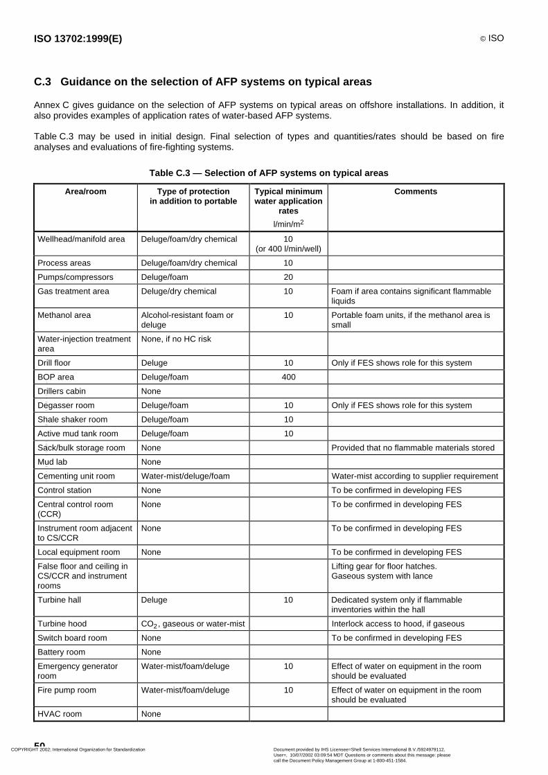
ISO 13702:1999(E) © ISO
50
C.3 Guidance on the selection of AFP systems on typical areas
Annex C gives guidance on the selection of AFP systems on typical areas on offshore installations. In addition, italso provides examples of application rates of water-based AFP systems.
Table C.3 may be used in initial design. Final selection of types and quantities/rates should be based on fireanalyses and evaluations of fire-fighting systems.
Table C.3 — Selection of AFP systems on typical areas
Area/room Type of protectionin addition to portable
Typical minimumwater application
rates
l/min/m2
Comments
Wellhead/manifold area Deluge/foam/dry chemical 10(or 400 l/min/well)
Process areas Deluge/foam/dry chemical 10
Pumps/compressors Deluge/foam 20
Gas treatment area Deluge/dry chemical 10 Foam if area contains significant flammableliquids
Methanol area Alcohol-resistant foam ordeluge
10 Portable foam units, if the methanol area issmall
Water-injection treatmentarea
None, if no HC risk
Drill floor Deluge 10 Only if FES shows role for this system
BOP area Deluge/foam 400
Drillers cabin None
Degasser room Deluge/foam 10 Only if FES shows role for this system
Shale shaker room Deluge/foam 10
Active mud tank room Deluge/foam 10
Sack/bulk storage room None Provided that no flammable materials stored
Mud lab None
Cementing unit room Water-mist/deluge/foam Water-mist according to supplier requirement
Control station None To be confirmed in developing FES
Central control room(CCR)
None To be confirmed in developing FES
Instrument room adjacentto CS/CCR
None To be confirmed in developing FES
Local equipment room None To be confirmed in developing FES
False floor and ceiling inCS/CCR and instrumentrooms
Lifting gear for floor hatches.Gaseous system with lance
Turbine hall Deluge 10 Dedicated system only if flammableinventories within the hall
Turbine hood CO2, gaseous or water-mist Interlock access to hood, if gaseous
Switch board room None To be confirmed in developing FES
Battery room None
Emergency generatorroom
Water-mist/foam/deluge 10 Effect of water on equipment in the roomshould be evaluated
Fire pump room Water-mist/foam/deluge 10 Effect of water on equipment in the roomshould be evaluated
HVAC room None
COPYRIGHT 2002; International Organization for Standardization
Document provided by IHS Licensee=Shell Services International B.V./5924979112,User=, 10/07/2002 03:09:54 MDT Questions or comments about this message: pleasecall the Document Policy Management Group at 1-800-451-1584.
-- | || | | |||| | | | ||| |||| || | | | |||| || | ---
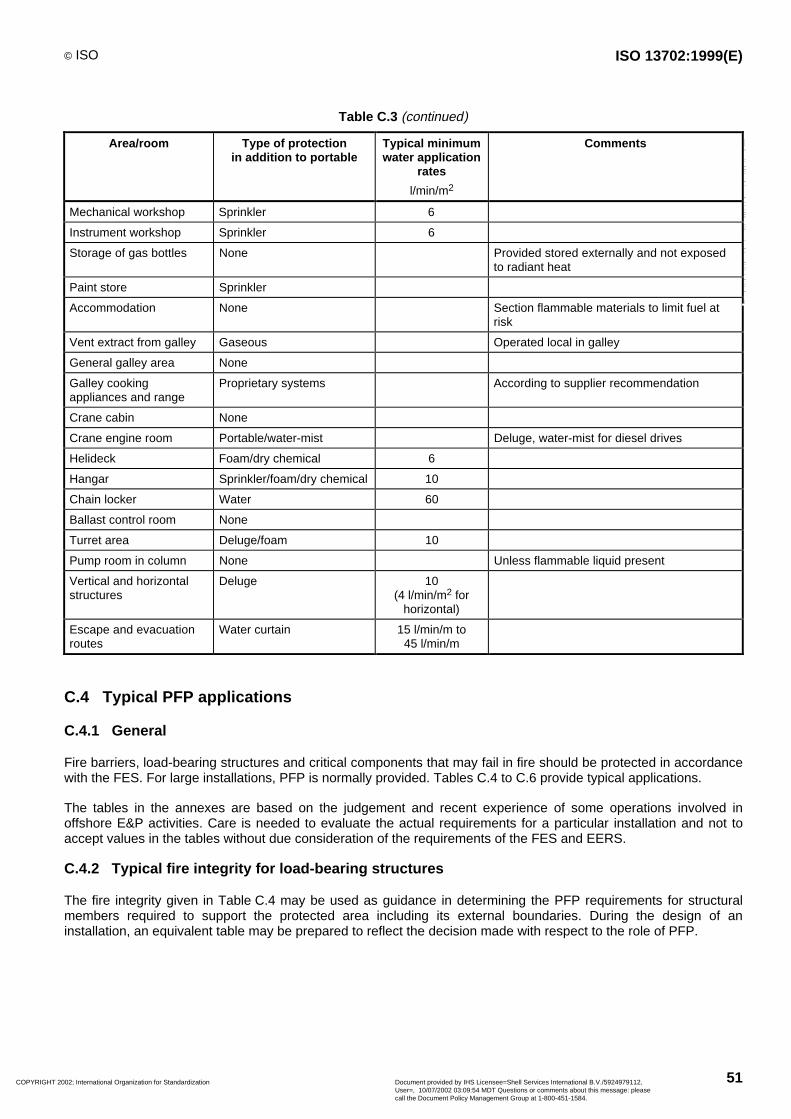
© ISO ISO 13702:1999(E)
51
Table C.3 (continued)
Area/room Type of protectionin addition to portable
Typical minimumwater application
rates
l/min/m2
Comments
Mechanical workshop Sprinkler 6
Instrument workshop Sprinkler 6
Storage of gas bottles None Provided stored externally and not exposedto radiant heat
Paint store Sprinkler
Accommodation None Section flammable materials to limit fuel atrisk
Vent extract from galley Gaseous Operated local in galley
General galley area None
Galley cookingappliances and range
Proprietary systems According to supplier recommendation
Crane cabin None
Crane engine room Portable/water-mist Deluge, water-mist for diesel drives
Helideck Foam/dry chemical 6
Hangar Sprinkler/foam/dry chemical 10
Chain locker Water 60
Ballast control room None
Turret area Deluge/foam 10
Pump room in column None Unless flammable liquid present
Vertical and horizontalstructures
Deluge 10(4 l/min/m2 for
horizontal)
Escape and evacuationroutes
Water curtain 15 l/min/m to45 l/min/m
C.4 Typical PFP applications
C.4.1 General
Fire barriers, load-bearing structures and critical components that may fail in fire should be protected in accordancewith the FES. For large installations, PFP is normally provided. Tables C.4 to C.6 provide typical applications.
The tables in the annexes are based on the judgement and recent experience of some operations involved inoffshore E&P activities. Care is needed to evaluate the actual requirements for a particular installation and not toaccept values in the tables without due consideration of the requirements of the FES and EERS.
C.4.2 Typical fire integrity for load-bearing structures
The fire integrity given in Table C.4 may be used as guidance in determining the PFP requirements for structuralmembers required to support the protected area including its external boundaries. During the design of aninstallation, an equivalent table may be prepared to reflect the decision made with respect to the role of PFP.
COPYRIGHT 2002; International Organization for Standardization
Document provided by IHS Licensee=Shell Services International B.V./5924979112,User=, 10/07/2002 03:09:54 MDT Questions or comments about this message: pleasecall the Document Policy Management Group at 1-800-451-1584.
-- | || | | |||| | | | ||| |||| || | | | |||| || | ---
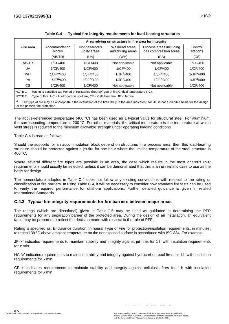
ISO 13702:1999(E) © ISO
52
Table C.4 — Typical fire integrity requirements for load-bearing structures
Area relying on structure in fire area for integrity
Fire area Accommodationblocks
(AB/TR)
Nonhazardousutility areas
(UA)
Wellhead areasand drilling areas
(WH)
Process areas includinggas compression areas
(PA)
Controlstations
(CS)
AB/TR 1/CF/400 1/CF/400 Not applicable Not applicable 1/CF/400
UA 1/CF/400 1/CF/400 1/CF/400 1/CF/400 1/CF/400
WH 1/JFa/400 1/JFa/400 1/JFa/400 1/JFa/400 1/JFa/400
PA 1/JFa/400 1/JFa/400 1/JFa/400 1/JFa/400 1/JFa/400
CS 1/CF/400 1/CF/400 Not applicable Not applicable 1/CF/400
NOTE 1 Rating is specified as: Period of resistance (hours)/Type of fire/Critical temperature (°C).
NOTE 2 Type of Fire: HC = Hydrocarbon pool fire, CF = Cellulosic fire, JF = Jet fire.
a 'HC' type of fire may be appropriate if the evaluation of the fires likely in the area indicates that 'JF' is not a credible basis for the designof the passive fire protection.
The above-referenced temperature (400 °C) has been used as a typical value for structural steel. For aluminium,the corresponding temperature is 200 °C. For other materials, the critical temperature is the temperature at whichyield stress is reduced to the minimum allowable strength under operating loading conditions.
Table C.4 is read as follows:
Should the supports for an accommodation block depend on structures in a process area, then this load-bearingstructure should be protected against a jet fire for one hour where the limiting temperature of the steel structure is400 °C.
Where several different fire types are possible in an area, the case which results in the most onerous PFPrequirements should usually be selected, unless it can be demonstrated that this is an unrealistic case to use as thebasis for design.
The nomenclature adopted in Table C.4 does not follow any existing conventions with respect to the rating orclassification of fire barriers. In using Table C.4, it will be necessary to consider how standard fire tests can be usedto verify the required performance for offshore applications. Further detailed guidance is given in relatedInternational Standards.
C.4.3 Typical fire integrity requirements for fire barriers between major areas
The ratings (which are directional) given in Table C.5 may be used as guidance in determining the PFPrequirements for any separation barrier of the protected area. During the design of an installation, an equivalenttable may be prepared to reflect the decision made with respect to the role of PFP.
Rating is specified as: Endurance duration, in hours/ Type of Fire for protection/insulation requirements, in minutes,to reach 139 °C above ambient temperature on the nonexposed surface in accordance with ISO 834. For example:
JF-'x ' indicates requirements to maintain stability and integrity against jet fires for 1 h with insulation requirementsfor x min.
HC-'x ' indicates requirements to maintain stability and integrity against hydrocarbon pool fires for 1 h with insulationrequirements for x min.
CF-'x ' indicates requirements to maintain stability and integrity against cellulosic fires for 1 h with insulationrequirements for x min.
COPYRIGHT 2002; International Organization for Standardization
Document provided by IHS Licensee=Shell Services International B.V./5924979112,User=, 10/07/2002 03:09:54 MDT Questions or comments about this message: pleasecall the Document Policy Management Group at 1-800-451-1584.
-- | || | | |||| | | | ||| |||| || | | | |||| || | ---

© ISO ISO 13702:1999(E)
53
Table C.5 — Typical fire integrity for fire barriers
Adjacent protected area
Fire area Accommodationblocks
(AB)
Nonhazardousutility areas
(UA)
Wellhead areasand drilling areas
(WH)
Process areas includinggas compression areas
(PA)
Controlstations
(CS)
AB 1/CF-60 1/CF-60 Not to beadjacent
1/CF-60 1/CF-60
UA 1/CF-60 1/CF-0 1/CF-0 1/CF-0 1/CF-60
WH Not to beadjacent
1/JFa-0 1/JFa-0 1/JFa-0 1/JFa-60
PA 1/JFa-120 1/JFa-60 1/JFa-0 1/JFa-0 1/JFa-60
CS 1/CF-60 1/CF-60 1/CF-60 1/CF-60 1/CF-60a 'HC' type of fire may be appropriate if the evaluation of the fires likely in the area indicates that 'JF' is not a credible basis for the designof the passive fire protection.
The nomenclature adopted in Table C.5 does not follow any existing conventions with respect to the rating orclassification of fire barriers. In using Table C.5, it will be necessary to consider how standard fire tests can be usedto verify the required performance for offshore applications. Further detailed guidance is given in relatedInternational Standards.
C.4.4 Typical fire integrity requirements for equipment
The fire integrity given in Table C.6 may be used as guidance in determining the PFP requirements for criticalequipment which may require PFP in order to allow it to fulfil its function in an emergency. During the design of aninstallation, an equivalent table may be prepared to reflect the decisions made with respect to the role of PFP.
Table C.6 — Typical protection criteria for critical equipment
Protection criteria
Surface temperature°C
Protection period
min
Riser sections < 200 a 60 b
Riser supports < 400 60 b
Riser topside SDV < 200 60 b
Fire pumps < 200 60
Emergency generators < 200 60
UPS systems 40 c 30
Control panels for SSIV/SSSV/BOP 40 c 15a In the absence of any knowledge as regards the relative location of the fire on the riser, the ESD valves and the contents of the riser, ithas been assumed that the fire is near the ESD valves and the riser is filled with liquid hydrocarbon. As a result, 200 °C has been used asthe default surface temperature for the riser sections to ensure the integrity of the ESD valves.b Or the minimum time period considered sufficient for a complete evacuation of the installation.c PFP may be provided to prevent temperature in the enclosure containing this equipment rising to these levels when subjected to anexternal fire.
C.5 Typical inspection and testing frequencies
As a minimum, plans for and periodicity inspection and testing should be established to ensure that there are nohidden failures which would prevent a system achieving the essential functions and reliability targets given in thefunctional requirements.
Table C.7 gives a summary of typical inspection and testing frequencies for the main equipment and systemsdiscussed in this International Standard which have been derived from API RP 14G.
COPYRIGHT 2002; International Organization for Standardization
Document provided by IHS Licensee=Shell Services International B.V./5924979112,User=, 10/07/2002 03:09:54 MDT Questions or comments about this message: pleasecall the Document Policy Management Group at 1-800-451-1584.
-- | || | | |||| | | | ||| |||| || | | | |||| || | ---

ISO 13702:1999(E) © ISO
54
Table C.7 — Inspection and testing matrix
Inspection testing and maintenance upkeep matrix
Equipment Periodicity
1 week 1 month 3 months 6 months 1 year
Fire & gas detection systems
Control panel F
Fire & gas general alarm F
Detectors (flame, heat, smoke, gas) C/F
Fire protection systems
Fixed gaseous systems a, b I/F
Deluge/sprinkler systems F
Deluge/sprinkler valve F
Fixed dry chemical systems a, c I
Fire hoses, nozzles & monitors I/F
Mobile & portable fire-fighting equipment I
Fire-water pump systems d, e, f F I/F
Communication systems
Public address systems g F
Main bearer radio F
Marine/aeronautical VHF systems
Fixed h F
Portable I/F
Aeronautical beacon F
Lifeboat radio I/F
Emergency shutdown systems
Control panel F
ESD I/O loops i F
Critical alarms/trips e.g. HH, LL F
ESD/EDP valves F
Electrical equipment
Emergency generator F
UPS battery chargers I/F
Emergency lighting F
Escape & evacuation equipment
Lifeboats j I/F
Life rafts k I
Tertiary escape equipment I
BA sets l I
C = Calibration; F = Function test; I = Inspection without dismantling.
a Gaseous systems include water-mist systems.b Inspection to include container mass/pressure checks.c Dry chemical storage cylinder to be inspected for contamination (annually).d Overhaul to be based upon weekly function test.e Pump performance test (annually).f Discharge test from at least two discharge points (annually).g PA central equipment to have daily function check.h Fixed VHF equipment require daily function check.i Overhaul/recalibration dependent on function test results.j Overhaul as required.k Recertified every 12 months.l Recertified every 5 years.
COPYRIGHT 2002; International Organization for Standardization
Document provided by IHS Licensee=Shell Services International B.V./5924979112,User=, 10/07/2002 03:09:54 MDT Questions or comments about this message: pleasecall the Document Policy Management Group at 1-800-451-1584.
-- | || | | |||| | | | ||| |||| || | | | |||| || | ---

© ISO ISO 13702:1999(E)
55
Bibliography
[1] ISO 834:1975, Fire resistance tests — Elements of building construction.
[2] ISO 10418:1993, Petroleum and natural gas industries — Offshore production platforms — Analysis, design,installation and testing of basic surface safety element.
[3] ISO 13819-1, Petroleum and natural gas industries — Offshore structures — Part 1: General requirements.
[4] ISO 13819-2, Petroleum and natural gas industries — Offshore structures — Part 2: Fixed steel structures.
[5] ISO 14001:1996, Environmental management systems — Specification with guidance for use.
[6] ISO 14004:1996, Environmental management systems — General guidelines on principles, systems andsupporting techniques.
[7] IEC 60079-10, Classification of Hazardous Areas.
[8] IEC 61508, Functional safety — Safety related systems, Parts 1 to 7.
[9] API RP 14J, Recommended Practice for Design and Hazard Analysis for Offshore Production Facilities.
[10] API RP 14 G, Recommended Practice for Fire Prevention and Control on Open Type Offshore ProductionPlatforms.
[11] API RP 75, Recommended Practice for Development of a Safety and Environmental Management Program forOuter Continental Shelf (OCS) Operation and Facilities.
[12] API RP 500, Recommended Practice for Classification of Locations for Electrical Installations at PetroleumFacilities.
[13] UKOOA — Guidelines for Fire and Explosion Hazard Management.
[14] UKOOA — Guidelines for Emergency Response.
[15] UKOOA — Guidelines for Safety-Related Telecommunications Systems on Normally-manned Fixed OffshoreInstallations.
[16] E&P Forum report No. 6.36/210, Guidelines for the Development and Application of Health, Safety andEnvironmental Management System.
[17] E&P Forum report No. 6.39/214, Guidance on Halon-Free Fire Protection.
[18] Christian Michelsen Research, Gas Explosion Handbook.
[19] Engineering Equipment and Materials Users Association (EEMUA), publication: 170, Recommendations for theProtection of Diesel Engines in Hazardous Areas.
[20] International Conference for the Safety of Life at Sea, 1974 (SOLAS 1974), Amendments 1986, IMO.
[21] Institute of Petroleum, Model Code of Safe Practice, Part 15: Area Classification Code for PetroleumInstallations.
[22] Steel Construction Institute, Interim Guidance Notes for the Design and Protection of Topsides Structuresagainst Explosion and Fire.
[23] SINTEF, Modelling of Hydrocarbon Fires Offshore, Final Report.
COPYRIGHT 2002; International Organization for Standardization
Document provided by IHS Licensee=Shell Services International B.V./5924979112,User=, 10/07/2002 03:09:54 MDT Questions or comments about this message: pleasecall the Document Policy Management Group at 1-800-451-1584.
-- | || | | |||| | | | ||| |||| || | | | |||| || | ---

ISO 13702:1999(E) © ISO
56
[24] TNO, Methods for the Calculation of the Physical effects of the Escape of dangerous materials.
[25] Offshore Technology Report OTI 95 634, Jet Fire Test for Determining the Effectiveness of Passive FireProtection Materials. UK Health and Safety Executive.
[26] National Fire Protection Association (NFPA) Standards.
COPYRIGHT 2002; International Organization for Standardization
Document provided by IHS Licensee=Shell Services International B.V./5924979112,User=, 10/07/2002 03:09:54 MDT Questions or comments about this message: pleasecall the Document Policy Management Group at 1-800-451-1584.
-- | || | | |||| | | | ||| |||| || | | | |||| || | ---

ISO 13702:1999(E) © ISO
ICS 75.180.10
Price based on 56 pages
COPYRIGHT 2002; International Organization for Standardization
Document provided by IHS Licensee=Shell Services International B.V./5924979112,User=, 10/07/2002 03:09:54 MDT Questions or comments about this message: pleasecall the Document Policy Management Group at 1-800-451-1584.
-- | || | | |||| | | | ||| |||| || | | | |||| || | ---

Nom du document: C022675E.DOCRépertoire: H:\SGML\CRCModèle: Y:\MODWW6\ISO30.DOTTitre: ISO/CEN 13703 E seulSujet: Petroleum and natural gas industry -Auteur: Billet JosianeMots clés:Commentaires: Dessins à insérerDate de création: 98-08-28 14:25N° de révision: 39Dernier enregistr. le: 99-03-05 11:56Dernier enregistr. par: Wanner ClaudeDurée totale d'ouverture du fichier: 387 minutesDernière impression sur: 99-03-05 11:56Tel qu'à la dernière impression
Nombre de pages: 62Nombre de mots: 26 191 (approx.)Nombre de caractères: 149 291 (approx.)
COPYRIGHT 2002; International Organization for Standardization
Document provided by IHS Licensee=Shell Services International B.V./5924979112,User=, 10/07/2002 03:09:54 MDT Questions or comments about this message: pleasecall the Document Policy Management Group at 1-800-451-1584.
-- | || | | |||| | | | ||| |||| || | | | |||| || | ---


![INTERNATIONAL ISO STANDARD 13678iso-iran.ir/standards/iso/ISO 13678-2009 , Petroleum and Natural... · This International Standard is based on API RP 5A3 [5], second edition, July](https://img.pdfslide.us/doc/110x75/5af2f19c7f8b9ac2469153c6/international-iso-standard-13678iso-iranirstandardsisoiso-13678-2009-petroleum.jpg)