Embed Size (px)
Citation preview

International Conference on Recent Trends in Civil Engineering, Technology and Management
(ICRTCETM-2017)
Seventh Sense Research Group www.internationaljournalssrg.org Page 1
IMPACT BEHAVIOUR OF GEOPOLYMER
FERROCEMENT TROUGH PANEL
Kaliraj. S[1] , Madasamy.P[2]
[1],[2]B.E Final year,
Department of Civil Engineering,
P.S.R. Engineering College,
Sivakasi, India
Dharmar.S [3] [3]Associate professor,
Department of Civil Engineering,
P.S.R. Engineering College,
Sivakasi, India.
Abstract— This paper deals with the study of impact
resistance and energy absorption properties of Geopolymer
Ferrocement Trough Panel under impact load. Geopolymer
is an eco-friendly binding material alternative for Ordinary
Portland Cement (OPC). In the last decade fly ash based
geopolymer has emerged as a promising new cement
alternative in the field of building and construction
materials. Ferrocement is a thin composite made with a fly
ash based mortar matrix reinforced with closely spaced
layers of relatively small diameter wire mesh. Over the
years, applications involving Ferrocement have increased
due to its properties such as strength, toughness, water
tightness, lightness, ductility and environmental stability.
This project aims to study and compare the structural
behaviour of Ferrocement trough panel and its mechanical
properties. These panels were subjected to impact loading
by drop weight test method. The panels were tested under a
drop weight of 75.50 N through a guide pipe from a height
of 460mm. It is concluded that Geopolymer Ferrocement
Trough Panels exhibits higher impact strength, while
compared with Geopolymer Ferrocement Flat panels based
on the experimental test results.
Keywords— Ferrocement, Geopolymer, Wire mesh,
Impact load.
I. INTRODUCTION
The capability to absorb energy, often called
‘toughness’, is of importance in actual service
conditions of mesh reinforced composites, when they
may be subjected to static, dynamic and fatigue loads.
Toughness evaluated under impact loads is the impact
strength. Impact resistance of any reinforced
composite can be measured by using a number of
different test methods, which can be broadly grouped
into the following categories.
a) Drop weight single or repeated impact test,
b) Constant strain rate test
c) Weighted pendulum charpy type impact test,
d) Explosion- impact test,
e) Projectile impact test,
f) Instrumented pendulum impact test,
g) Split Hopkinson bar test.
Several methods have been reported to
evaluate the impact characteristics of concrete/cement
composites. Of these, the simplest and most widely
used test is the drop-weight test, which can be used to
evaluate the relative performance of composites.
Reported work on the impact behavior of
Ferrocement slabs relates to the use of conventional
reinforcement (chicken mesh and M.S. skeletal) and
drop-weight method (instrumented/ordinary falling
weight). Hence, in the present study drop-weight
method was selected and used to study the impact
characteristics of slab specimens. Ferrocement has
been used for various offshore and marine structures,
roofing, water tanks, grain silos and biogas plants.
Even though conventional Ferrocement using
ordinary cement mortar as matrix satisfies most
general requirements, Ferrocement products which
have higher ultimate moment and toughness are
required for some special applications in ocean
engineering and the chemical industry. Portland
cement is the most common type of cement used in
construction applications, but it is an expensive
binder due to the high cost of production associated
with the high energy requirements of the
manufacturing process itself. The contribution of
ordinary Portland cement production worldwide to
greenhouse gas emission is approximately 7% of the
total greenhouse gas emission to the atmosphere. The
production of 1 ton ordinary Portland cement
consumes 4GJ energy and produces about 1 ton of
carbon dioxide (Co2) to the atmosphere. About half of
the Co2 emissions from Portland cement production
are due to calcination of limestone, while the other
half are due to combustion of fossil fuel for the above
reasons, recent research works are focusing on the
feasibility of replacing cement with different types of
waste products. Fly ash has gained prominence as the
most commonly used waste material for partially
replacing cement. A promising research outcome
developed in the last decade is low calcium fly ash
based geopolymer cement and concrete. Geopolymers
prepared by using the low calcium fly ash exhibit
high compressive strength, low creep, minimal drying
shrinkage, good acid resistance, fire resistance. The
authors have conducted impact test to study the
International Conference on Recent Trends in Civil Engineering, Technology and Management
(ICRTCETM-2017)
Seventh Sense Research Group www.internationaljournalssrg.org Page 2
properties of geopolymer Ferrocement prepared with
10 molarity (M) geopolymer mortar which show
excellent properties compared with the ordinary
cement mortar.
II. LITERATURE REVIEW
In the experimental work carried out by S. Nagan
and R.Mohana (2014)1, they found the resistance of
geopolymer mortar slabs under impact load by
dropping a steel ball from a considerable height. For
this study, they used specimens of size 230 x 230 x
25 mm with different combinations of chicken mesh
and rectangular weld mesh and are subjected to
impact load by drop weight test and the impact
energy required for first crack and final crack were
calculated. They found that the combination of
chicken mesh and rectangular weld mesh together
showed better performance in case of energy
absorption and residual impact strength. The
compressive strength, flexural strength and split
tensile strength of 10M geopolymer mortar specimens
are found to be 36.05%, 33% and 27.7% more when
compared to cement mortar specimens respectively.
Also with increase in volume of reinforcement,
energy absorption of geopolymer ferrocement
specimen increases compared to cement mortar
specimen.
In this experimental investigation, Dr. Abdulkader
Ismail Al-Hadithi et al. (2014)2, studied the
behaviour of ferrocement slabs under impact load by
varying the parameters like number of layers of
meshes, SBR polymer content and height of fall. For
this study, they used specimens of size 500 x 500 x
50 mm and weight of fall is about 1.3 kg and the
height of fall is 2.5m, 1.2m and 0.83m. The
specimens were casted and tested at an age of 56 days
and the no. of blows required for first and final crack
were recorded. The impact resistance capacity of the
specimens was calculated. They concluded that, the
impact energy absorption capacity of the ferrocement
specimen increases as the polymer content percentage
and the number of layersof wire mesh increases.
III. RESEARCH SIGNIFICANCE
In this investigation, the experiments were conducted
to understand the structural behavior of Geopolymer
Ferrocement Panels under impact loading. The tests
were mainly focused on the impact load test of
geopolymer Ferrocement Panels with all the four
edges in fixed condition by drop weight test. This
paper presents the no. of blows required for first
crack stage, ultimate stage, impact load and energy
absorption at first crack and ultimate stage.
IV. MATERIALS
a. Fly Ash Fly ash is the most abundantly used mineral
admixture as replacement for cement in mortar. It is
also the main ingredient for geopolymer mortar due
to its active participation in the geopolymerization
process. Pozzolanic material exhibits cementitious
properties when combined with calcium hydroxide.
Fly ash is used as the pozzolana in many concrete
applications. Fly ash is used as cement replacement.
b. Fine Aggregate Locally obtained trichy river sand is used as the fine
aggregate in the mortar mixes. The sieve analysis
result indicates that the sand confirms to zone-II as
per IS: 383- 1970.
c. Sodium Hydroxide Generally, NaOH is available in market in pellets or
flakes form with 96% to 98% purity where the cost of
the product depends on the purity of the material. The
solution of NaOH was formed by dissolving it in
water based on the molarity required. It is
recommended that the NaOH solution should be
made 24 hours before casting and should be used
with 36 hours of mixing the pellets with water as after
that it is converted to semi-solid state.
d. Sodium Silicate It is also known as water-glass which is available in
the market in gel form. The ratio of SiO2 and Na2O in
sodium silicate gel highly affects the strength of
geopolymer mortar. Mainly it is seen that a ratio
ranging from 1 to 1.5 gives a satisfactory result.
e. Wire Mesh
Steel wire meshes are considered as primary
reinforcement. This include square woven or welded
meshes, chicken (hexagonal/aviary) wire mesh, etc.
Except for expanded metal mesh, generally all the
meshes are used galvanized. Galvanizes chicken wire
mesh with a hexagonal opening of size 12 mm and
wire thickness of 1.29 mm was used in this study.
V. MIX PROPORTION AND EXPERIMENTAL
INVESTIGATION
a. Geopolymer Mix Design
Sodium hydroxide concentration = 10 M
Na2SiO3 to NaOH ratio = 1:1.50
Fly ash to Sand ratio = 1:1
Alkaline activator to Fly ash ratio = 0.45
Curing type = oven curing
Curing period (oven) = 24 hrs@72°c
-75°c
b. Preparation of Alkaline Activator Solution The mixture of Na2SiO3 solution and NaOH solution
can be used as the alkaline liquid. The Alkali
activator solution has to be prepared before 24 hours
of use because at the time of mixing Na2SiO3 and
NaOH solution it generates a huge amount of heat
and the polymerization takes place by reacting with
one another, which will act as a binder in the
geopolymer mortar. It should be used within 36 hours
International Conference on Recent Trends in Civil Engineering, Technology and Management
(ICRTCETM-2017)
Seventh Sense Research Group www.internationaljournalssrg.org Page 3
of mixing the pellets with water as after that it is
converted to semi-solid state. The Sodium hydroxide,
available in small flakes, is dissolved in water at
different proportions as required molarity of solution.
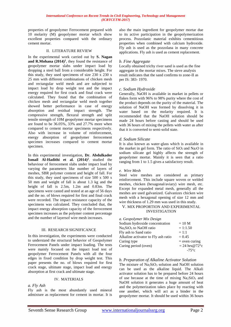
c. Geometry of mould
Geometry shape of Ferrocement panel will be casted
using geopolymer mortar and the size of panels. The
tested ferrocement panels consist of two Trough
panels. The dimensions of the trough are shown in
Fig. (1) which depicts that the horizontal projection
of the trough panel is (350x200mm) dimensions. The
thickness of the panels is 30mm.The panels are
constructed using the conventional ferrocement
materials, which is composed of cement mortar and
Galvanizes chicken wire mesh with a hexagonal.
Figure 1. Dimensions of the Trough panel
d. Casting of geopolymer ferrocement panels
Special mould was fabricated in metal sheet to match
the required geometry of the folded trough panel.
Each sample is molded after fixing the required wire
mesh and skeletal steel in its proper position. For the
panels with single wire mesh top of the skeletal steel.
Then the panels were cast in sodium hydroxide
concentration 10M, sodium hydroxide to sodium
silicate ratio 1:1.50, fly ash to sand ratio of 1:1 and
alkaline activator to fly ash ratio of 0.45 with proper
compaction. The moulds were coated initially with oil
so as to enable easy removal of the moulds. The
moulds were placed on an even surface. The surface
was painted with waste oil. Cover blocks were used
to ensure a clear cover of 5 mm. Normal mild steel
bars steel bars (nominal diameters 6 mm) were used
as the reinforcing material. The steel reinforcement
mat with required spacing was placed inside the
moulds.
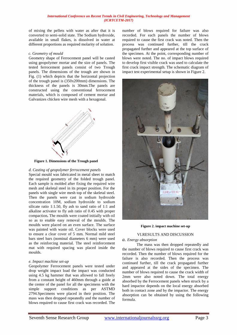
e. Impact machine set-up
Geopolymer Ferrocement panels were tested under
drop weight impact load the impact was conducted
using 4.5 kg hammer that was allowed to fall freely
from a constant height of 460mm through a guide at
the center of the panel for all the specimens with the
simple support conditions as per ASTMD
2794.Specimens were placed in their position. The
mass was then dropped repeatedly and the number of
blows required to cause first crack was recorded. The
number of blows required for failure was also
recorded. For each panels the number of blows
required to cause the first crack was noted. Then the
process was continued further, till the crack
propagated further and appeared at the top surface of
the specimen. At the point, corresponding number of
blows were noted. The no. of impact blows required
to develop first visible crack was used to calculate the
first crack impact strength. The schematic diagram of
impact test experimental setup is shown in Figure 2.
Figure 2. impact machine set-up
VI.RESULTS AND DISCUSSION
a. Energy absorption
The mass was then dropped repeatedly and
the number of blows required to cause first crack was
recorded. Then the number of blows required for the
failure is also recorded. Then the process was
continued further, till the crack propagated further
and appeared at the sides of the specimen. The
number of blows required to cause the crack width of
2mm were also noted down. The total energy
absorbed by the Ferrocement panels when struck by a
hard impactor depends on the local energy absorbed
both in contact zone and by the impactor. The energy
absorption can be obtained by using the following
formula.
International Conference on Recent Trends in Civil Engineering, Technology and Management
(ICRTCETM-2017)
Seventh Sense Research Group www.internationaljournalssrg.org Page 4
E= N x (w x h) joules
Where,
E= energy in joules
w= weight in Newton
h= drop height in meter
N= blows in numbers
The ratio of energy absorbed up to the
failure of specimens to the energy absorbed at
initiation of first crack is defined as the 'Residual
Impact Strength Ratio' (Irs). The energy absorption
capacities of Ferrocement slab specimens at first
crack and at ultimate failure stages are presented.
Table 1 Impact Resistance of Geopolymer Ferrocement Panels
S.
No.
Specimens
ID
First Crack
Resistance
– FCR (No.
of blows)
Ultimate
Resistance
– UR (No.
of blows)
Percent
increase
in
Resistance
from FCR
to UR
1
GFP TH 01 8 22 1.75
GFP TH 02 9 25 1.74
Table 2 Impact Energy of Geopolymer Ferrocement Panels
S.
No
Specimens
ID
Impact Energy
Absorbed (Joules)
Impact
Strength Ratio
(Irs) At First
Crack
At
Ultimate
1
GFP TH 01 165.60 455.40 2.75
GFP TH 02 186.30 517.50 278
Figure 3 At first crack
Figure .4 At Ultimate
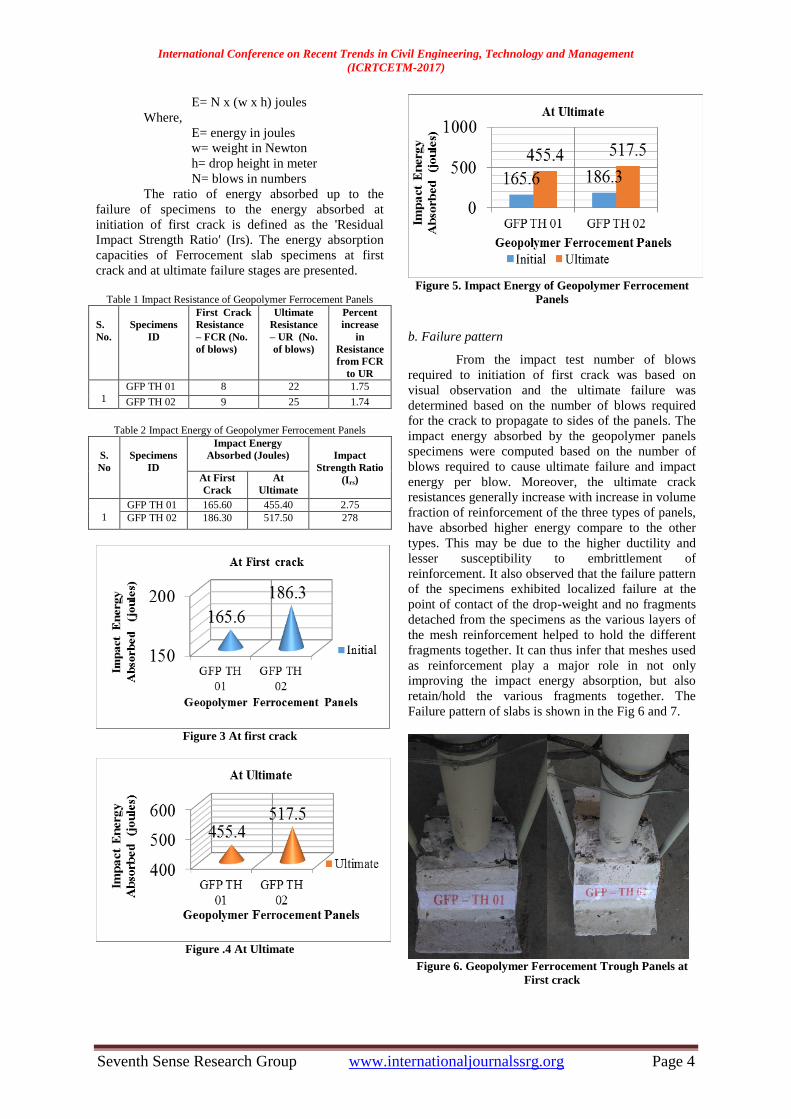
Figure 5. Impact Energy of Geopolymer Ferrocement
Panels
b. Failure pattern
From the impact test number of blows
required to initiation of first crack was based on
visual observation and the ultimate failure was
determined based on the number of blows required
for the crack to propagate to sides of the panels. The
impact energy absorbed by the geopolymer panels
specimens were computed based on the number of
blows required to cause ultimate failure and impact
energy per blow. Moreover, the ultimate crack
resistances generally increase with increase in volume
fraction of reinforcement of the three types of panels,
have absorbed higher energy compare to the other
types. This may be due to the higher ductility and
lesser susceptibility to embrittlement of
reinforcement. It also observed that the failure pattern
of the specimens exhibited localized failure at the
point of contact of the drop-weight and no fragments
detached from the specimens as the various layers of
the mesh reinforcement helped to hold the different
fragments together. It can thus infer that meshes used
as reinforcement play a major role in not only
improving the impact energy absorption, but also
retain/hold the various fragments together. The
Failure pattern of slabs is shown in the Fig 6 and 7.
Figure 6. Geopolymer Ferrocement Trough Panels at
First crack

International Conference on Recent Trends in Civil Engineering, Technology and Management
(ICRTCETM-2017)
Seventh Sense Research Group www.internationaljournalssrg.org Page 5
Figure 7. Geopolymer Ferrocement Trough Panels at
failure
V. CONCLUSIONS
Based on the above experimental results, the
following conclusions are arrived
1) Increase in the volume of reinforcement the energy
absorption is also increased when compared to the
control mix.
2) The failure pattern in the impact tested panels is
found to be punching shear due to higher
reinforcement. Only pure cracks are propagated up to
the edge.
3) The energy absorbed at failure is directly
proportional to the volume of the reinforcement
provided in the Geopolymer Ferrocement panels.
4) Increase in molarity of NaOH also increases first
crack impact strength and ultimate impact strength of
Geopolymer concrete panels.
5) Geopolymer Ferrocement Trough Panels exhibits
higher impact strength, while compared with
geopolymer Ferrocement Flat panels based on the
experimental test results.
References
1. S. Nagan and R. Mohana (2015) “Behavior
of geopolymer Ferrocement slabs
subjected to impact” IJST, Transactions of
Civil Engineering, Vol. 38, No. C1+, pp
223-233.
2. Saranyabanu, S.Dharmar, Dr.S.Nagan,
“Flexural Behavior of Trough Shaped
Ferrocement Panels” International Journal
of Innovative Research in Science,
Engineering and Technology.
3. Vincent Prabakar Rajaiah, S.Dharmar,
Dr.S.Nagan, “Experimental Investigation
on Flexural Behavior of Folded
Ferrocement Panels” International Journal
of Innovative Research in Science,
Engineering and Technology.
4. R. Padmavathy, S.Dharmar et.al, “Study on
Flexural Behavior of Flat Ferrocement
Panels ” International Journal of Science
and Research (IJSR).
5. Mohamad N. Mahmood & Sura A. Majeed
(2009) “Flexural Behavior Of Flat And
Folded Ferrocement Panels” Al-Rafidain
Engineering Volume: 17 No: : 4 August
2009
6. G. Murali, E. Arun, A. Arun Prasadh, R.
Infant raj and T. Aswin Prasanth et.al,
“Experimental Investigation of
Reinforced Ferrocement Concrete Plates
under Impact Load” International Journal
of Latest Research in Engineering and
Computing (IJLREC).